JP6496551B2 - Seismic isolation device - Google Patents
Seismic isolation device Download PDFInfo
- Publication number
- JP6496551B2 JP6496551B2 JP2015000711A JP2015000711A JP6496551B2 JP 6496551 B2 JP6496551 B2 JP 6496551B2 JP 2015000711 A JP2015000711 A JP 2015000711A JP 2015000711 A JP2015000711 A JP 2015000711A JP 6496551 B2 JP6496551 B2 JP 6496551B2
- Authority
- JP
- Japan
- Prior art keywords
- support
- wheel
- seismic isolation
- vibration
- isolation device
- Prior art date
- Legal status (The legal status is an assumption and is not a legal conclusion. Google has not performed a legal analysis and makes no representation as to the accuracy of the status listed.)
- Active
Links
- 238000002955 isolation Methods 0.000 title claims description 63
- 238000013016 damping Methods 0.000 description 21
- 230000033001 locomotion Effects 0.000 description 18
- 230000001133 acceleration Effects 0.000 description 12
- 230000004044 response Effects 0.000 description 12
- 230000002238 attenuated effect Effects 0.000 description 11
- 230000003247 decreasing effect Effects 0.000 description 11
- 230000000694 effects Effects 0.000 description 10
- 230000001629 suppression Effects 0.000 description 8
- 230000009467 reduction Effects 0.000 description 7
- 230000007246 mechanism Effects 0.000 description 6
- 230000008859 change Effects 0.000 description 5
- 230000007423 decrease Effects 0.000 description 5
- 238000005086 pumping Methods 0.000 description 5
- JOYRKODLDBILNP-UHFFFAOYSA-N Ethyl urethane Chemical compound CCOC(N)=O JOYRKODLDBILNP-UHFFFAOYSA-N 0.000 description 3
- 238000005516 engineering process Methods 0.000 description 2
- 239000002184 metal Substances 0.000 description 2
- 230000002093 peripheral effect Effects 0.000 description 2
- 230000000630 rising effect Effects 0.000 description 2
- 238000005452 bending Methods 0.000 description 1
- 238000010586 diagram Methods 0.000 description 1
- 230000005489 elastic deformation Effects 0.000 description 1
- 230000006872 improvement Effects 0.000 description 1
- 238000009434 installation Methods 0.000 description 1
- 239000000463 material Substances 0.000 description 1
- 238000000034 method Methods 0.000 description 1
- 230000004048 modification Effects 0.000 description 1
- 238000012986 modification Methods 0.000 description 1
- 230000008569 process Effects 0.000 description 1
- 230000002787 reinforcement Effects 0.000 description 1
- 230000007480 spreading Effects 0.000 description 1
- 238000006467 substitution reaction Methods 0.000 description 1
Images

Landscapes
- Buildings Adapted To Withstand Abnormal External Influences (AREA)
- Vibration Prevention Devices (AREA)
- Bearings For Parts Moving Linearly (AREA)
Description
本発明は、地震等の際に支持体が移動や振動をしても制動または免震を行えるようにした免震装置に関する。 The present invention relates to a seismic isolation device that can perform braking or seismic isolation even when a support moves or vibrates during an earthquake or the like.
従来、地震に対する構造安全性や居住性の向上を実現する技術として免震構造技術が存在する。免震構造とは、上部構造物とそれを支える下部構造物の間に、免震装置や減衰装置を配置し、地震の揺れを直接上部構造物に伝えないようにした構造システムである。その形態は、建物全体を免震化した免震建物や、居室の一部、あるいは機器等を免震対象とした免震床や免震台などが存在する。
このような構造システムでは、地震による激しい振動が発生しても、下部構造物に対して免震装置や減衰装置を介することで上部構造物はゆったりと揺れ、単純に固定された場合に比べて、上部構造物の加速度応答が低減される。このことにより、構造の安全性や居住性の向上を図ることができる。
Conventionally, there is a seismic isolation structure technology as a technology for realizing an improvement in structural safety and habitability against earthquakes. The seismic isolation structure is a structural system in which seismic isolation devices and damping devices are arranged between the upper structure and the lower structure that supports it, so that earthquake vibrations are not transmitted directly to the upper structure. As for the form, there are seismic isolation buildings in which the entire building is seismically isolated, seismic isolation floors and bases for seismic isolation of a part of a room or equipment.
In such a structural system, even if severe vibrations occur due to an earthquake, the upper structure is gently shaken by the seismic isolation device and the damping device with respect to the lower structure, compared with the case where it is simply fixed. The acceleration response of the superstructure is reduced. As a result, it is possible to improve the safety and comfort of the structure.
このような免震構造システムを実現するために、免震装置や減衰装置の水平方向の剛性は比較的小さくする必要がある。そのため、それらが存在する免震層には大きな変形が発生する。場合によっては、変形が想定よりも過大になり、許容変形量を超過して衝突する可能性も考えられ、このような場合には大きな衝撃を受ける。このような変形をなるべく小さくするために免震構造物には減衰機構が導入されている。 In order to realize such a seismic isolation system, the horizontal rigidity of the seismic isolation device and the damping device needs to be relatively small. Therefore, a large deformation occurs in the seismic isolation layer where they exist. In some cases, the deformation becomes excessive than expected, and there is a possibility of collision exceeding the allowable deformation amount. In such a case, a large impact is received. In order to minimize such deformation as much as possible, a damping mechanism has been introduced into the seismic isolation structure.
一般的に、減衰機構を多く導入するほど免震層の変形量を小さくできるが、その場合、上部構造物の加速度応答が大きくなる。逆に、減衰機構を少なめに導入すると上部構造物の加速度応答を小さくできるが、今度は免震層の変形量が大きくなる。通常、免震構造物の設計の際には、加速度応答低減効果と変形量抑制効果の両者を見て、バランスの良い設計が行われるが、これらの効果の両立には限界があった。 In general, the more the damping mechanism is introduced, the smaller the amount of deformation of the seismic isolation layer, but in that case, the acceleration response of the superstructure increases. Conversely, if the damping mechanism is introduced in a small amount, the acceleration response of the superstructure can be reduced, but this time the amount of deformation of the seismic isolation layer increases. Normally, when designing a base-isolated structure, a well-balanced design is performed in view of both the acceleration response reduction effect and the deformation suppression effect, but there is a limit to the compatibility of these effects.
例えば特許文献1に記載された免震装置では、下部構造物に設置した基台と上部構造物に連結した架台とにX−Y方向に配設した凹曲面をなす下部レール及び上部レールと下部レール及び上部レールにそれぞれ当接するローラーとを免震層として設けている。即ち、基台には下部レールと上部レールに当接するローラーとが設置され、被免震物には下向きの上部レールと下部レールに当接するローラーとが設置されている。
そして、地震時には架台と基台との間に設けた上下部レールと各ローラーとで相対的に摺動して振動することで免震性能を発揮する。しかも、地震終了後には上下部レールが凹曲面状に湾曲形成されていることで被免震物が上下部レールの中央位置に復帰するようになっている。
For example, in the seismic isolation device described in
And at the time of an earthquake, a seismic isolation performance is exhibited by vibrating by sliding relatively with an up-and-down rail provided between a mount and a base, and each roller. In addition, the seismic isolation object returns to the center position of the upper and lower rails because the upper and lower rails are formed in a concave curved shape after the earthquake.
ところで、特許文献1に記載された免震装置では、上下部レールがそれぞれ凹曲面状に形成されているために振動終了後に各凹曲面の中央位置に各ローラーが復帰するが、振動時の減衰特性はレール全域においてほぼ一定となっている。また、免震装置の許容変形量は、免震装置自体のしくみや免震装置を設置する場所の条件により決定され、必要なだけ大きな変形量を確保するということはできない。
そのため、加速度応答低減効果を高める場合は減衰特性が小さく設定されるため、免震装置が設置される場所に許容される地震動の大きさは、衝突をさせないという免震装置の変形量に支配される。一方、変形量抑制効果を高めることは減衰特性を大きくすることにより可能であり、より大きな地震動に対しても免震装置の変形量を許容変形量以下とすることができるが、減衰特性が大きいため、大きな地震動のみでなく小さな地震動の場合でも上部構造物に大きな加速度を発生させてしまうという欠点があった。
By the way, in the seismic isolation device described in
For this reason, when the acceleration response reduction effect is enhanced, the damping characteristic is set to be small, so the magnitude of seismic motion allowed in the place where the seismic isolation device is installed is governed by the amount of deformation of the seismic isolation device that does not cause a collision. The On the other hand, it is possible to enhance the deformation suppression effect by increasing the damping characteristics, and the deformation amount of the seismic isolation device can be made less than the allowable deformation amount even for larger earthquake motions, but the damping characteristics are large For this reason, there is a drawback in that a large acceleration is generated not only in a large earthquake motion but also in a small earthquake motion.
本発明は、このような事情に鑑みてなされたものであり、構造物等を支持する支持体の加速度応答低減効果と変形量抑制効果をバランスさせると共に、支持体の振動等を効率よく低減できるようにした免震装置を提供することを目的とする。 The present invention has been made in view of such circumstances, and can balance the acceleration response reduction effect and deformation amount suppression effect of a support that supports a structure or the like, and can efficiently reduce vibrations of the support. An object is to provide a seismic isolation device .
本発明による免震装置は、構造物に設けた支持体と、支持体の可動方向に沿って設けた静止体と、静止体と支持体の一方に設けた軸部に偏心して回転可能に設けられていて静止体と支持体の他方を押圧して支持体の移動を減衰させる変形可能な車輪と、を備え、前記支持体には振動後に基準位置に復帰させるための弾性部材が設置されていることを特徴とする。
本発明によれば、支持体が静止体に沿って移動した際に、支持体または静止体に設けた車輪が軸部に偏心して回転することで静止体または支持体を押圧して変形することで両者の間に発生する摩擦抵抗によって支持体の移動を減衰させて制振することができる。しかも、複数の車輪を配設した場合、各車輪の角度を一致させて回転による摩擦抵抗を同時に増減調整してもよいし、各車輪の角度を異ならせて個別に増減調整してもよい。
しかも、地震時等に、支持体の振動による移動を車輪の弾性変更によって摩擦抵抗を発揮させて制振させた際、弾性部材の付勢力によって減衰した振動に打ち勝って支持体を基準位置に復帰させることができる。
The seismic isolation device according to the present invention is provided to be rotatable eccentrically on a support provided on a structure, a stationary body provided along a movable direction of the support, and a shaft provided on one of the stationary body and the support. And a deformable wheel that presses the other of the stationary body and the support body to attenuate the movement of the support body, and the support body is provided with an elastic member for returning to the reference position after vibration and said that you are.
According to the present invention, when the support body moves along the stationary body, the support body or the wheel provided on the stationary body rotates eccentrically with the shaft portion so that the stationary body or the support body is pressed and deformed. Thus, the movement of the support can be damped by the frictional resistance generated between them. In addition, when a plurality of wheels are provided, the frictional resistance due to rotation may be increased or decreased simultaneously by matching the angles of the wheels, or may be individually increased or decreased by changing the angles of the wheels.
In addition, in the event of an earthquake or the like, when the movement due to the vibration of the support body is controlled by changing the elasticity of the wheels to exert a frictional resistance, the vibrations attenuated by the urging force of the elastic member are overcome and the support body is returned to the reference position. Can be made.
また、支持体は、ガイドレールに沿って移動可能としてもよい。
地震等の際に支持体がガイドレールに沿って振動するために、支持体と静止体の一方に設けた車輪を支持体と静止体の他方に押圧させて摩擦抵抗によって制振することができる。
Further, the support may be movable along the guide rail.
Since the support body vibrates along the guide rail in the event of an earthquake or the like, the wheel provided on one of the support body and the stationary body can be pressed against the other of the support body and the stationary body and can be controlled by frictional resistance. .
本発明による免震装置は、構造物に設けた支持体と、支持体の可動方向に沿って設けられていて支持体との距離が次第に短くなる傾斜部を有する静止体と、支持体に設けた軸部に回転可能に設けられていて静止体の傾斜部を押圧して支持体を制振する車輪とを備え、傾斜部と車輪の一方が弾性変形可能であることを特徴とする。
本発明によれば、支持体が静止体に沿って移動した際に、車輪が静止体の傾斜部を押圧していずれか一方を弾性変形させることで車輪と静止体の間に発生する摩擦抵抗によって支持体の振動を減衰させて制振することができる。
なお、車輪は軸部に偏心して回転可能に設けられていてもよい。
The seismic isolation device according to the present invention includes a support provided on a structure, a stationary body provided along the movable direction of the support and having an inclined portion in which the distance from the support gradually becomes shorter, and the support. And a wheel that is rotatably provided on the shaft portion and presses the inclined portion of the stationary body to dampen the support, and one of the inclined portion and the wheel is elastically deformable.
According to the present invention, when the support moves along the stationary body, the frictional resistance generated between the wheel and the stationary body by the wheel pressing the inclined portion of the stationary body and elastically deforming one of the wheels. Thus, the vibration of the support can be damped and suppressed.
In addition, the wheel may be provided so as to be able to rotate eccentrically with the shaft portion.
本発明による免震装置によれば、地震等による支持体の移動や振動の際に偏心した車輪と静止体を互いに押圧して変形させ、しかも車輪を回転させることで変形量を変化させて摩擦抵抗を増減調整して強弱の変化で制動または制振して、効率よく移動や振動を減衰できる。そのため、本発明によれば、支持体の摩擦抵抗を増減調整することによって、構造物等を支持する支持体の加速度応答低減効果と変形量抑制効果をバランスさせると共に、支持体の移動や振動等を効率よく減衰できる。 According to the seismic isolation device that by the present invention, by pressing together the eccentric wheel and a stationary member during the movement or vibration of the support due to an earthquake or the like is deformed, yet alter the amount of deformation by rotating the wheel The frictional resistance can be increased or decreased, and braking or damping can be performed by changing the strength to efficiently attenuate movement and vibration. Therefore, according to the present invention, by adjusting the frictional resistance of the support to increase or decrease, the acceleration response reduction effect and the deformation suppression effect of the support that supports the structure and the like are balanced, and the support is moved and vibrated. Can be attenuated efficiently.
また、本発明による免震装置によれば、支持体の車輪と静止体の傾斜部とを互いに押圧して変形させることで次第に摩擦抵抗を増大させることで、効率よく移動や振動を減衰できる。そのため、本発明によれば、支持体の摩擦抵抗を調整することによって、構造物等を支持する支持体の加速度応答低減効果と変形量抑制効果をバランスさせると共に、支持体の移動や振動等を効率よく減衰できる。 In addition, according to the seismic isolation device of the present invention, movement and vibration can be efficiently damped by gradually increasing the frictional resistance by pressing and deforming the wheels of the support and the inclined portion of the stationary body. Therefore, according to the present invention, by adjusting the frictional resistance of the support, the acceleration response reduction effect and the deformation suppression effect of the support that supports the structure and the like are balanced, and the movement and vibration of the support are reduced. Can be attenuated efficiently.
以下、本発明の第一実施形態による減衰機構を備えた免震装置1について図1から図5に基づいて説明する。
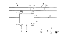
図1から図3は本発明の第一実施形態による免震装置1を示すものであり、建物等の構造物の耐震補強のために用いられる。
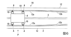
本実施形態による免震装置1を構築する下部構造物2には、例えば直線状のガイドレール3が設置され、ガイドレール3上には例えばブロック状の支持体4が設置されている。支持体4は例えば所定間隔で縦横方向に複数個設置され、その上部には構造物が設置されている。ガイドレール3は例えば縦方向または横方向に略平行に複数配設され、各ガイドレール3に沿って構造物を部分的に支える支持体4が所定間隔で複数本設置されているものとし、図1では1つの支持体4と1条のガイドレール3を示している。
Hereinafter, a
1 to 3 show a
For example, a
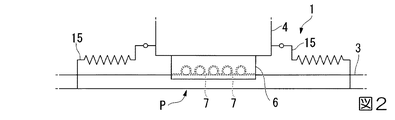
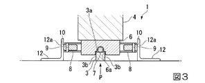
図2及び図3において、構造物を支える支持体4の下部には基部6が固定され、基部6の下面にはガイドレール3に嵌合されてガイドレール3の天面である摺動面3aと両側面3bに対向する凹部6aが形成されている。凹部6a内の底面には摺動可能な複数のベアリング7が軸受に回転可能に装着されている。なお、凹部6aの側面側やコーナー部にもベアリングが装着されていてもよい。複数のベアリング7は凹部6aの延在方向に所定間隔で設置され、ガイドレール3の摺動面3aに当接して支持体4を揺動可能としている。支持体4は常態において予め設定された基準位置Pに保持されて構造物を支持し、地震等の際には下部構造物2の振動が伝達されてガイドレール3に沿って揺動可能とされている。なお、基部6または支持体4の上部にはガイドレール3に直交する方向に図示しない別の基部6とガイドレール3が配列されている。これによって免振装置1は構造物を直交する2方向の振動に対応して揺動可能に支持している。
2 and 3, a
また、基部6の両側面には上下の支持枠8が水平方向に突出しており、上下の支持枠8間に固定された軸部9には円盤状の車輪10が回転可能に支持されている。車輪10は例えばゴムやウレタン等の弾性体や粘弾性体で変形可能に形成されている。車輪10は軸部9に対して偏心していて回転可能に取り付けられており、軸部9を中心とした車輪10の回転によって車輪10は外側に進退可能とされている。また、車輪10はその回転位置にかかわらず支持体4に非接触となるように支持枠8の長さが設定されている。
なお、図に示す例では、車輪10は支持体4の基部6の両側面に2基ずつ設置されているが、1基または3基以上設けてもよい。
Further, upper and lower support frames 8 protrude horizontally on both side surfaces of the
In the example shown in the figure, two
また、図1及び図3において、ガイドレール3の両側には間隔をあけて、例えば断面略L字状のガイド部材12がガイドレール3と平行に設置されており、その起立面をガイド壁12aとして示すものとする。なお、ガイド部材12に代えて壁面等が設置されていてもよい。
そして、図1に示す構造物の設置位置の原点となる静止位置を基準位置Pとし、この位置にある車輪10を図4の拡大図に示す。図4に示す車輪10において、偏心した車輪10の回転中心である軸部9から最も近い距離の外周面の位置をA点とし、A点から左右方向に90度回転した位置をB点、180度回転した位置をC点という。免震装置1の基準位置Pにおいて、車輪10はA点でガイド部材12のガイド壁12aに当接し、そのガイド壁12aとの押圧強度は車輪10の周方向で最も小さく、支持体4が振動等で移動するとA点に当接して車輪10が軸部9を中心に回転することになる。
1 and 3, a
And the stationary position used as the origin of the installation position of the structure shown in FIG. 1 is made into the reference position P, and the
また、地震等によって免震装置1が振動して支持体4がガイドレール3に沿って移動すると、車輪10がガイド壁12aに当接して回転し、ガイド壁12aに当接する位置が、B点、C点、B点と変化する。A点では車輪10がガイド壁12aに当接する程度であり、C点で最も強くガイド壁12aに押圧され、B点ではC点とA点の中間程度の強度でガイド壁12aに押圧されて摩擦抵抗を生じるようになっている。しかも、車輪10が各点A,B,Cでガイド壁12aに押圧されると、車輪10はその押圧強度に応じて圧接されて弾性変形する。
また、支持体4のガイドレール3に沿った両側にばね15の一端が連結され、他端は下部構造物2に固定されている。そのため、地震等の際には支持体4は振動によってガイドレール3に沿って移動可能であるが、振動が終息後またはばね15の付勢力未満となった場合には支持体4はばね15の付勢力によって基準位置Pに戻るようになっている。
Further, when the
One end of the
本実施形態による免震装置1は、地震等によって支持体4が振動し移動すると、ガイド壁12aに当接する車輪10が回転して、A点からB点、C点とガイド壁12aに対する押圧圧力が増大して摩擦抵抗が増大し、減衰機能を発揮する。そして、車輪10のC点がガイド壁12aに当接すると弾性変形と摩擦抵抗が最大になり、その後、B点を介してA点で摩擦抵抗が最小になる。
そのため、支持体4が振動した際に車輪10が軸部9を中心に偏心回転することで、ガイド壁12aに圧接されて摩擦抵抗が変化し、その摩擦抵抗力で減衰効果、制動効果を生じるため、いわゆるポンピングブレーキのような機能を発揮できる。
In the
Therefore, when the
本実施形態による免震装置1は上述の構成を備えており、次に免震装置1による免震方法について図5を中心に説明する。
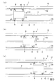
地震の発生していない状態では、図5(a)に示すように、建築物等の構造物を支える各支持体4はその両側のガイド部材12のガイド壁12a間に挟まれた基準位置Pで安定した状態に保持される。そして、地震発生時には下部構造物2の振動によってガイドレール3に対して支持体4がばね15の付勢力に抗して相対的に振動し、支持体4はガイドレール3の摺動面3aに沿ってベアリング7で摺動する。
The
In a state where no earthquake has occurred, as shown in FIG. 5A, each
すると、図5(b)に示すように、支持体4の一方向の移動によってガイド部材12のガイド壁12aに当接する車輪10が90度回転することでガイド壁12aへの当接位置がA点からB点に変位し、車輪10はより強くガイド壁12aに押圧されて次第に変形し、支持体4の移動に対する摩擦抵抗が増大する。そして、車輪10が更に90度回転し、図5(c)に示すように、ガイド壁12aに押圧する位置がB点からC点に移動すると車輪10が一層ガイド壁12aに強く押圧されて更に大きく変形し、最も摩擦抵抗が大きくなる。こうして支持体4の振動によるガイドレール3に沿った移動に強い制動がかけられる。
そして、支持体4の移動によって車輪10は更に90度回転してガイド壁12aへの当接位置がC点からB点に変位し、更に90度回転してB点からA点に変位することで摩擦抵抗による制動力は次第に減衰する。
Then, as shown in FIG. 5B, the
As the
こうして、支持体4の振動によって車輪10がガイド壁12aに押圧力の増減による摩擦抵抗の増減を繰り返しながら複数回の回転を繰り返すことでポンピングブレーキのように強度が増減する摩擦力が働いて振動を減衰させる。そして摩擦力によって支持体4の移動が停止する。
次に、地震によって支持体4が逆方向に振動して、同様に回転する車輪10のガイド壁12aへの押圧変形力の増減によって摩擦抵抗が増減し、振動が減衰して停止する。
Thus, the vibration of the
Next, the
こうして、ガイドレール3に沿った支持体4の往復振動を繰り返しながら、車輪10のガイド壁12aへの摩擦抵抗の増減を繰り返して支持体4は振動を次第に減衰させる。そして支持体4は地震等による振動力が0に近く減衰させられると、ばね15の付勢力によって基準位置Pに戻り、静止する。この位置で車輪10はA点でガイド壁12aに当接し、ほぼ円形状に弾性復帰する。
そのため、地震の震度が小さい場合には、車輪10の回転によるポンピングブレーキ状の増減変動する摩擦抵抗によって、車輪10の少ない回転数による支持体4の少ない移動距離で振動が減衰して停止し、地震の震度が大きい場合には車輪10の比較的大きな回転数と支持体4の比較的大きな移動距離によって振動が繰り返されて減衰して停止する。
In this way, while repeating the reciprocating vibration of the
Therefore, when the seismic intensity of the earthquake is small, the vibration is attenuated and stopped at a small moving distance of the
なお、上述した説明では、基準位置Pにある支持体4の各車輪10は軸部9との距離が最も小さいA点でガイド部材12のガイド壁12aに当接し、摩擦抵抗の最も小さい角度に位置する。そのため、地震が発生した場合、震度の小さい地震でも支持体4は移動し易いという特性を有している。これに対し、基準位置Pにおいて、車輪10がB点やC点等でガイド壁12aに当接していると、地震時に初期振動に対する摩擦による移動抵抗が大きく、小さな地震時の支持体4の移動を抑制できることになる。
In the above description, each
上述のように本実施形態による免震装置1によれば、地震等の際に支持体4がガイドレール3に沿って往復振動しても、両側の車輪10が軸部9に偏心して支持されてガイド壁12aに押圧されているために、支持体4の移動によって車輪10が偏心回転することでガイド壁12aとの間で摩擦抵抗がポンピングブレーキ状に増減変動して制動と制振を働かせることができる。そのため、支持体4で保持された建造物等の構造物の加速度応答を低減させながら車輪10の変形量の抑制を達成でき、振動を効率よく減衰させて免震することができる。
特に、本実施形態では、加速度応答低減効果と変形量抑制効果をバランスさせて制振できる。
As described above, according to the
In particular, in the present embodiment, vibration can be controlled by balancing the acceleration response reduction effect and the deformation amount suppression effect.
なお、本発明は上述の実施形態による免震装置1に限定されることはなく、本発明の要旨を変更しない範囲で適宜の変更や置換等が可能であり、これらはいずれも本発明に含まれる。以下に、本発明の変形例や他の実施形態について説明するが、上述の実施形態と同一または同様な部分、部材には同一の符号を用いて説明を省略する。
例えば、上述した実施形態では、支持体4の両側に取り付けた4つの車輪10は基準位置Pにおいて軸部9から最も距離の短いA点がガイド壁12aに当接し、支持体4の移動によって4つの車輪10で同期してB点,C点がガイド壁12aに押圧変形されて摩擦抵抗が増減するようにしたが、車輪10を個別に異なる点でガイド壁12aに当接させてもよい。この場合、支持体4の振動に対する摩擦抵抗の増減変動が小さくなる。
In addition, this invention is not limited to the
For example, in the above-described embodiment, the four
次に本発明の第二実施形態による免震装置1Aについて図6により説明する。
図6に示す免震装置1Aにおいて、支持体4に設けた各車輪10は中心に軸部9が取り付けられ、偏心していない。そして、ガイドレール3の両側に配設させたガイド部材12は支持体4の基準位置Pから離間した位置から次第にガイド壁12aがガイドレール3側に湾曲する湾曲部12bが形成されている。
Next, a seismic isolation device 1A according to a second embodiment of the present invention will be described with reference to FIG.
In the
そのため、地震等で支持体4が振動した場合、振動で移動する支持体4は両側に設けた車輪10がガイド部材12のガイド壁12aに沿って摺動し、湾曲部12bに至ると次第に湾曲するガイド壁12aの湾曲部12bによって車輪10との摩擦力が増大して制動がかけられる。しかも、ガイド壁12aの湾曲部12bは次第にガイドレール3側に湾曲するため、次第に車輪10との間の摩擦力が増大し、徐々に制動がかけられて停止する。
そして、支持体4が逆方向に振動すると、同様に逆方向のガイド壁12aの湾曲部12bで次第に増大する制動がかけられる。こうして支持体4は左右方向に振動しつつ減衰させられ、振動が0に近くなるとばね15の付勢力が振動力に打ち勝って支持体4を基準位置Pに戻す。
Therefore, when the
And if the
本第二実施形態の場合、車輪10を湾曲部12bで弾性変形させて制動させてもよく、車輪10はゴムやウレタン等の弾性部材で形成することが好ましい。また、この構成に代えて、車輪10を金属等の剛性の高い物質で形成し、ガイド壁12aの湾曲部12bにゴム板やウレタン板等のシート状の弾性部材を貼り付けるようにしてもよい。
In the case of the second embodiment, the
或いは、車輪10を第一実施形態のようにゴム等の弾性部材で形成し、しかも軸部9に偏心させて取り付けるようにしてもよい。この場合、ガイド壁12aの湾曲部12bは金属等の高剛性部材でもよいし、弾性部材でもよい。
この場合には、車輪10による制動力が第一実施形態の場合よりも大きくなる上に、湾曲部12bを移動する車輪10の摩擦抵抗がポンピングブレーキのように増減変動して、制動力が増減変動する特性を呈するため、加速度応答低減効果と変形量抑制効果をバランスさせることができる。
また、ガイド部材12のガイド壁12aに形成した湾曲部12bに代えて直線状の傾斜部を設けてもよく、本明細書の傾斜部は湾曲部12bと直線状の傾斜部の両方を含むものとする。
Alternatively, the
In this case, the braking force by the
Moreover, it may replace with the
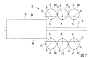
次に本発明の第三実施形態による免震装置1Bについて図7及び図8により説明する。
図7及び図8に示す免震装置1Bにおいて、支持体4に車輪10を設けていない。車輪10はガイドレール3の両側で支持体4が基準位置Pから移動した際に支持体4の側面4aによって押圧可能な位置に複数配列されている。車輪10は偏心した位置で下部構造物2等から起立する軸部9に回転可能に支持されており、複数の軸部9はガイドレール3に平行な直線L上に所定間隔で配列されていることが好ましい。
各車輪10について、上述した第一実施形態と同様に、軸部9から最も径方向の距離が短い外周面の位置をA点、A点と180度対向する位置で軸部9から最も径方向の距離が長い位置をC点、A,C点から90度離れた両側の位置をB点とする。
Next, a
In the
For each
支持体4が基準位置Pにある場合、図7に示すように、支持体4から離間した各車輪10はいずれもA点がガイドレール3側に位置しているものとする。そして、地震等が発生した場合、基準位置Pに保持された支持体4は振動によってガイドレール3に沿って移動し始める。すると、支持体4に最も近接する位置にある両側の車輪10(これを便宜的に第一の車輪10Aとする)が支持体4の側面4aの先端に押されて軸部9回りに回転すると、支持体4は90度回転した車輪10のB点に押されて摩擦抵抗を受けるため、振動が減衰される。B点で支持体4の側面4aを押圧する車輪10は当接面が広がって変形し圧縮される。
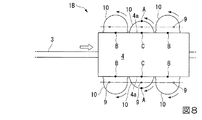
更に移動する支持体4は次の車輪10(これを第二の車輪10Bとする)を軸部9回りに回転させて変形させて同様にB点で押される。このとき、第一の車輪10Aは押圧する支持体4の側面4aに更に押されて回転するため、C点で支持体4を強く押圧し最も扁平に変形される。支持体4は車輪10のC点で押されることで最も高強度の押圧力を受けて最も高い摩擦力を支持体4に与えて振動を減衰させる。
When the
Further, the moving
また、更に振動で移動する支持体4は次の車輪10(これを第三の車輪10Cとする)を軸部9回りに回転させて同様にB点で支持体4は押される。このとき、図8に示すように、第一の車輪10Aは押圧する支持体4の側面4aに更に押されて回転するため、B点で支持体4を押圧して変形し、第二の車輪10Bは支持体4の側面4aに更に押されて回転するため、C点で広く圧縮変形して支持体4を最も強く押す。この状態で、支持体4は両側の3組の車輪10で最も強い制動を受けて一層減衰させられ、この位置で振動が大きく低減され、摩擦抵抗の増減変動によって強弱の変化で振動を減衰させられて静止するものとする。
そして、振動の復帰力により、または、ばね15の付勢力により、支持体4は逆方向に移動し始め、反対側に同様に配列された車輪10によって同様に増減変動する摩擦抵抗によって減衰させられる。
こうして支持体4は左右方向に振動しつつ強弱の変化で減衰させられ、振動が0に近くなるとばね15の付勢力が振動力に打ち勝って支持体4は基準位置Pに戻される。
Further, the
The
Thus, the
なお、第三実施形態において、地震の震度が小さければ、1対または2対の車輪10に押圧されることで支持体4が振動を減衰させることができる。
また、支持体4の移動方向に設置する車輪10は3つに限定されるものではなく、その設置数は任意である。
In addition, in 3rd embodiment, if the seismic intensity of an earthquake is small, the
Further, the number of
なお、上述した各実施形態では、ガイドレール3が直動ガイドレールであるが、本発明は直線状のガイドレール3に限定されるものではなく、湾曲したカーブ状のガイドレール3を採用してもよい。この場合、ガイドレール3に沿って一対のガイド部材12も同様に湾曲形成させる。
また、各実施形態ではガイドレール3に沿って振動可能な支持体4の両側にガイド部材12や車輪10を設けたが、ガイド部材12や車輪10はガイドレール3の片側にだけ設けていてもよい。この場合でも振動の減衰を達成することができる。
In each of the above-described embodiments, the
In each embodiment, the
また、本実施形態では、免震装置1においてガイドレール3の両側または片側にガイド部材12または車輪10を配設して減衰機構を設置したが、本発明はこのような構成に限定されるものではない。
例えば、第三実施形態において、複数の車輪10を任意の間隔で設置して支持体4の制振を行うようにしてもよく、車輪10は任意の支持体4の振動を制御するために適宜の位置に設置できる。そのため、支持体4の振動または移動方向と車輪10の軸部9とが同一間隔であれば、支持体4のガイドレール3を設置しなくてもよい。
Moreover, in this embodiment, although the
For example, in the third embodiment, a plurality of
なお、上述した実施形態では地震の際の免震装置1の減衰機構について説明したが、本発明は免震装置1に限定されるものではなく、走行する支持体4の制動をガイドする制動装置に採用してもよい。
しかも、複数の車輪10を配設した場合、各車輪10のA,B,C点の角度を一致させて回転による摩擦抵抗を同時に増減調整してもよいし、各車輪のA,B,C点の角度を異ならせて個別に摩擦抵抗と制振力を増減調整してもよい。
また、本発明において、支持体4の車輪10は押圧部材を構成する。ガイド部材12や軸部9を支持する下部構造物2等は静止体を構成する。
In the above-described embodiment, the damping mechanism of the
In addition, when a plurality of
Moreover, in this invention, the
1 免震装置
2 下部構造物
3 ガイドレール
4 支持体
6 基部
7 ベアリング
8 支持枠
9 軸部
10 車輪
12 ガイド部材
12a ガイド壁
12b 湾曲部
15 ばね
P 基準位置
DESCRIPTION OF
Claims (4)
前記支持体の可動方向に沿って設けた静止体と、
前記静止体と支持体の一方に設けた軸部に偏心して回転可能に設けられていて前記静止体と支持体の他方を押圧して前記支持体を制動する変形可能な車輪と、
を備え、前記支持体には振動後に基準位置に復帰させるための弾性部材が設置されていることを特徴とする免震装置。 A support provided on the structure;
A stationary body provided along the movable direction of the support;
A deformable wheel that is eccentrically provided on a shaft portion provided on one of the stationary body and the support body and is rotatably provided and presses the other of the stationary body and the support body to brake the support body;
And the support is provided with an elastic member for returning to a reference position after vibration .
前記支持体の可動方向に沿って設けられていて前記支持体との距離が次第に短くなる傾斜部を有する静止体と、
前記支持体に設けた軸部に回転可能に設けられていて前記静止体の傾斜部を押圧して前記支持体を制振する車輪と、
を備え、前記傾斜部と車輪の一方が変形可能であることを特徴とする免震装置。 A support provided on the structure;
A stationary body provided along the movable direction of the support body and having an inclined portion in which the distance from the support body is gradually shortened;
A wheel that is rotatably provided on a shaft provided on the support and presses the inclined portion of the stationary body to dampen the support; and
A seismic isolation device characterized in that one of the inclined portion and the wheel is deformable.
Priority Applications (1)
| Application Number | Priority Date | Filing Date | Title |
|---|---|---|---|
| JP2015000711A JP6496551B2 (en) | 2015-01-06 | 2015-01-06 | Seismic isolation device |
Applications Claiming Priority (1)
| Application Number | Priority Date | Filing Date | Title |
|---|---|---|---|
| JP2015000711A JP6496551B2 (en) | 2015-01-06 | 2015-01-06 | Seismic isolation device |
Publications (2)
| Publication Number | Publication Date |
|---|---|
| JP2016125607A JP2016125607A (en) | 2016-07-11 |
| JP6496551B2 true JP6496551B2 (en) | 2019-04-03 |
Family
ID=56357679
Family Applications (1)
| Application Number | Title | Priority Date | Filing Date |
|---|---|---|---|
| JP2015000711A Active JP6496551B2 (en) | 2015-01-06 | 2015-01-06 | Seismic isolation device |
Country Status (1)
| Country | Link |
|---|---|
| JP (1) | JP6496551B2 (en) |
Families Citing this family (2)
| Publication number | Priority date | Publication date | Assignee | Title |
|---|---|---|---|---|
| JP6957874B2 (en) * | 2016-12-27 | 2021-11-02 | セイコーエプソン株式会社 | Mobile support device and printing device |
| JP2021050483A (en) * | 2019-09-24 | 2021-04-01 | 三井住友建設株式会社 | Base isolation device and base isolation body equipped with the same |
Family Cites Families (9)
| Publication number | Priority date | Publication date | Assignee | Title |
|---|---|---|---|---|
| JPS59162565U (en) * | 1983-04-18 | 1984-10-31 | 日立プラント建設株式会社 | Elevator fall prevention device |
| JPH0674609B2 (en) * | 1988-08-19 | 1994-09-21 | 将男 秋元 | Seismic isolation device and seismic isolation structure |
| JPH0367900A (en) * | 1989-08-03 | 1991-03-22 | Akio Matsui | Braking device of moving object |
| JPH07109821A (en) * | 1993-10-12 | 1995-04-25 | Toyo Constr Co Ltd | Floor base isolation device |
| JPH11293954A (en) * | 1998-04-15 | 1999-10-26 | Toyo Tire & Rubber Co Ltd | Vibration isolation device for residence |
| JP4118417B2 (en) * | 1998-10-19 | 2008-07-16 | 株式会社奥村組 | Lift prevention device in seismic isolation device for structures |
| SE523190C2 (en) * | 2001-12-21 | 2004-03-30 | Flexlink Components Ab | Device for braking arrangements therewith and method of braking |
| JP5578516B2 (en) * | 2009-07-30 | 2014-08-27 | 学校法人明治大学 | Damping device and damping method |
| JP2012237434A (en) * | 2011-05-09 | 2012-12-06 | Tsutomu Yoneyama | Base isolation device |
-
2015
- 2015-01-06 JP JP2015000711A patent/JP6496551B2/en active Active
Also Published As
| Publication number | Publication date |
|---|---|
| JP2016125607A (en) | 2016-07-11 |
Similar Documents
| Publication | Publication Date | Title |
|---|---|---|
| TWI683720B (en) | Up and down shock-free device | |
| US20120153551A1 (en) | Suspension device for vehicle seats and/or vehicle cabins having an elastomer member | |
| JP6217181B2 (en) | Floor seismic isolation system | |
| JP6496551B2 (en) | Seismic isolation device | |
| KR101969079B1 (en) | Ceiling plumbing cradle of double earthquake resistant structure | |
| JP4593552B2 (en) | Vertical seismic isolation device | |
| JP4822132B2 (en) | Vertical seismic isolation mechanism | |
| JP4761347B2 (en) | Building vibration control system. | |
| JP6491856B2 (en) | Braking and seismic isolation devices | |
| JPH02107843A (en) | Three dimentional oscillation isolating device | |
| JP6761699B2 (en) | Vibration damping device | |
| JP4822133B2 (en) | Displacement expansion mechanism, damping damper and seismic isolation mechanism | |
| JP6274172B2 (en) | Seismic isolation table device | |
| JP2015105554A (en) | Base-isolation structure | |
| JP2019052454A (en) | Aseismic isolation structure | |
| CN101346557B (en) | Negative rigidity device and vibration isolating construction provided with this negative rigidity device | |
| JP4613333B2 (en) | Seismic isolation device | |
| JP2011038617A (en) | Pantograph type base isolation system | |
| JP2012021638A (en) | Base isolation device | |
| JP2006183681A (en) | Vertical base-isolating unit and base-isolating device using the same | |
| JP4786363B2 (en) | Vibration isolator | |
| JP6629650B2 (en) | Method of reducing peak of acceleration generated in base-isolated structure and base-isolated structure | |
| JP2016151278A (en) | Vibration control device | |
| JPH10280726A (en) | Vibration control mechanism | |
| JP4064563B2 (en) | Exhibit seismic isolation device |
Legal Events
| Date | Code | Title | Description |
|---|---|---|---|
| A621 | Written request for application examination |
Free format text: JAPANESE INTERMEDIATE CODE: A621 Effective date: 20171115 |
|
| A977 | Report on retrieval |
Free format text: JAPANESE INTERMEDIATE CODE: A971007 Effective date: 20180918 |
|
| A131 | Notification of reasons for refusal |
Free format text: JAPANESE INTERMEDIATE CODE: A131 Effective date: 20181002 |
|
| A521 | Request for written amendment filed |
Free format text: JAPANESE INTERMEDIATE CODE: A523 Effective date: 20181129 |
|
| TRDD | Decision of grant or rejection written | ||
| A01 | Written decision to grant a patent or to grant a registration (utility model) |
Free format text: JAPANESE INTERMEDIATE CODE: A01 Effective date: 20190212 |
|
| A61 | First payment of annual fees (during grant procedure) |
Free format text: JAPANESE INTERMEDIATE CODE: A61 Effective date: 20190311 |
|
| R150 | Certificate of patent or registration of utility model |
Ref document number: 6496551 Country of ref document: JP Free format text: JAPANESE INTERMEDIATE CODE: R150 |
|
| R250 | Receipt of annual fees |
Free format text: JAPANESE INTERMEDIATE CODE: R250 |
|
| R250 | Receipt of annual fees |
Free format text: JAPANESE INTERMEDIATE CODE: R250 |
|
| R250 | Receipt of annual fees |
Free format text: JAPANESE INTERMEDIATE CODE: R250 |