JP6496324B2 - Catheter connector fixture - Google Patents
Catheter connector fixture Download PDFInfo
- Publication number
- JP6496324B2 JP6496324B2 JP2016554931A JP2016554931A JP6496324B2 JP 6496324 B2 JP6496324 B2 JP 6496324B2 JP 2016554931 A JP2016554931 A JP 2016554931A JP 2016554931 A JP2016554931 A JP 2016554931A JP 6496324 B2 JP6496324 B2 JP 6496324B2
- Authority
- JP
- Japan
- Prior art keywords
- outer peripheral
- peripheral wall
- catheter
- connector
- cover member
- Prior art date
- Legal status (The legal status is an assumption and is not a legal conclusion. Google has not performed a legal analysis and makes no representation as to the accuracy of the status listed.)
- Active
Links
- 230000002093 peripheral effect Effects 0.000 claims description 60
- 239000012530 fluid Substances 0.000 claims description 14
- 239000000853 adhesive Substances 0.000 claims description 7
- 230000001070 adhesive effect Effects 0.000 claims description 7
- 239000004615 ingredient Substances 0.000 claims 1
- 238000003780 insertion Methods 0.000 description 7
- 230000037431 insertion Effects 0.000 description 7
- 241001670157 Gymnura Species 0.000 description 6
- 238000006073 displacement reaction Methods 0.000 description 2
- 238000000034 method Methods 0.000 description 2
- 238000012986 modification Methods 0.000 description 2
- 230000004048 modification Effects 0.000 description 2
- 239000000356 contaminant Substances 0.000 description 1
- 229940079593 drug Drugs 0.000 description 1
- 239000003814 drug Substances 0.000 description 1
- 239000006260 foam Substances 0.000 description 1
- 238000001802 infusion Methods 0.000 description 1
- 238000012423 maintenance Methods 0.000 description 1
- 230000014759 maintenance of location Effects 0.000 description 1
- 238000007726 management method Methods 0.000 description 1
- 239000000463 material Substances 0.000 description 1
Images


Classifications
-
- A—HUMAN NECESSITIES
- A61—MEDICAL OR VETERINARY SCIENCE; HYGIENE
- A61M—DEVICES FOR INTRODUCING MEDIA INTO, OR ONTO, THE BODY; DEVICES FOR TRANSDUCING BODY MEDIA OR FOR TAKING MEDIA FROM THE BODY; DEVICES FOR PRODUCING OR ENDING SLEEP OR STUPOR
- A61M25/00—Catheters; Hollow probes
-
- A—HUMAN NECESSITIES
- A61—MEDICAL OR VETERINARY SCIENCE; HYGIENE
- A61M—DEVICES FOR INTRODUCING MEDIA INTO, OR ONTO, THE BODY; DEVICES FOR TRANSDUCING BODY MEDIA OR FOR TAKING MEDIA FROM THE BODY; DEVICES FOR PRODUCING OR ENDING SLEEP OR STUPOR
- A61M25/00—Catheters; Hollow probes
- A61M25/01—Introducing, guiding, advancing, emplacing or holding catheters
- A61M25/02—Holding devices, e.g. on the body
- A61M2025/024—Holding devices, e.g. on the body having a clip or clamp system
-
- A—HUMAN NECESSITIES
- A61—MEDICAL OR VETERINARY SCIENCE; HYGIENE
- A61M—DEVICES FOR INTRODUCING MEDIA INTO, OR ONTO, THE BODY; DEVICES FOR TRANSDUCING BODY MEDIA OR FOR TAKING MEDIA FROM THE BODY; DEVICES FOR PRODUCING OR ENDING SLEEP OR STUPOR
- A61M25/00—Catheters; Hollow probes
- A61M25/01—Introducing, guiding, advancing, emplacing or holding catheters
- A61M25/02—Holding devices, e.g. on the body
- A61M2025/0246—Holding devices, e.g. on the body fixed on the skin having a cover for covering the holding means
-
- A—HUMAN NECESSITIES
- A61—MEDICAL OR VETERINARY SCIENCE; HYGIENE
- A61M—DEVICES FOR INTRODUCING MEDIA INTO, OR ONTO, THE BODY; DEVICES FOR TRANSDUCING BODY MEDIA OR FOR TAKING MEDIA FROM THE BODY; DEVICES FOR PRODUCING OR ENDING SLEEP OR STUPOR
- A61M25/00—Catheters; Hollow probes
- A61M25/01—Introducing, guiding, advancing, emplacing or holding catheters
- A61M25/02—Holding devices, e.g. on the body
- A61M2025/0266—Holding devices, e.g. on the body using pads, patches, tapes or the like
-
- A—HUMAN NECESSITIES
- A61—MEDICAL OR VETERINARY SCIENCE; HYGIENE
- A61M—DEVICES FOR INTRODUCING MEDIA INTO, OR ONTO, THE BODY; DEVICES FOR TRANSDUCING BODY MEDIA OR FOR TAKING MEDIA FROM THE BODY; DEVICES FOR PRODUCING OR ENDING SLEEP OR STUPOR
- A61M25/00—Catheters; Hollow probes
- A61M25/01—Introducing, guiding, advancing, emplacing or holding catheters
- A61M25/02—Holding devices, e.g. on the body
- A61M2025/028—Holding devices, e.g. on the body having a mainly rigid support structure
Description
本発明は、概して医療カテーテルの分野に関し、より詳細にはカテーテルコネクタ用の固定具に関する。 The present invention relates generally to the field of medical catheters, and more particularly to fasteners for catheter connectors.
様々な医療処置のために、カテーテルを使用して患者に流体を送達するまたは患者から流体を引き出すことがよく知られている。例えば、米国特許第7,959,623号明細書(特許文献1)には、様々な実施形態の注入カテーテルを使用して、ポンプからチューブを介して創傷部位に流体薬剤を送達する疼痛管理システムが記載されている。このようなシステムでは、カテーテルを様々な器具、例えばチューブ、リザーバ(流体貯蔵タンク)、または他の流体送達デバイスなどに接続するのに、通常はカテーテルコネクタが使用される。特許文献1のシステムでは、カテーテルの近位端に医療用チューブの遠位端を接続するのに、従来のトーイボースト(Toughy Borst)型コネクタが使用される。 For various medical procedures, it is well known to use a catheter to deliver fluid to or withdraw fluid from a patient. For example, U.S. Patent No. 7,959,623 discloses a pain management system that uses an infusion catheter of various embodiments to deliver fluid medication from a pump through a tube to a wound site. Is described. In such systems, catheter connectors are typically used to connect the catheter to various instruments, such as tubes, reservoirs (fluid storage tanks), or other fluid delivery devices. In the system of U.S. Pat. No. 6,057,836, a conventional Toughy Borst connector is used to connect the distal end of the medical tube to the proximal end of the catheter.
トーイボースト型コネクタに加えて、様々な他の構成のカテーテルコネクタが利用可能である。例えば、米国テキサス州ファーマーズブランチ所在のエピメッド・インターナショナル社(Epimed International)により、「スティングレイ(Stingray)(商標)コネクタ」として知られているロープロファイル型のツイストロック式カテーテルコネクタが製造されている。このコネクタは、軸方向に整列して配置された2つの部分(第1の部分および第2の部分)を有しており、第1および第2の部分を互いに対して回転させて開位置にすると、第1の部分においてカテーテルを挿入することができ、その後にさらに回転させて閉位置にすると、カチッという音および触覚によりカテーテルとの完全な係合を確認することができる。コネクタを介してカテーテルに流体を送達するために、第2の部分は、チューブまたは他の流体送達デバイスに接続される。 In addition to a toy boast type connector, various other configurations of catheter connectors are available. For example, Epimed International, Farmers Branch, Texas, USA, manufactures a low profile twist-lock catheter connector known as "Stingray (TM) Connector". This connector has two parts (first part and second part) arranged in axial alignment, and the first and second parts are rotated relative to each other to the open position. Then, the catheter can be inserted in the first portion, and when it is further rotated to the closed position, complete engagement with the catheter can be confirmed by clicking and touching. The second portion is connected to a tube or other fluid delivery device for delivering fluid to the catheter via the connector.
英国のスミス・メディカル・インターナショナル社(Smiths Medical International Ltd.)からは、リビングヒンジにより互いに結合された2つの部分から成るカテーテルコネクタが「EpiFuse(商標)」という商品名で提供されている。カテーテルは、このコネクタのベース部に形成された孔に挿入され、コネクタの2つの部分が折り畳まれて互いに対してロックされたときに位置固定される。 Smiths Medical International Ltd. of the UK offers a two-part catheter connector under the trade name "EpiFuse (TM)" joined together by a living hinge. The catheter is inserted into a hole formed in the base of the connector and is fixed when the two parts of the connector are folded and locked relative to each other.
多くの場合、このようなカテーテルおよびコネクタの使用は、長期の治療期間にわたって維持する必要がある。これらのカテーテルをテープにより固定することが、周知の手法であった。しかしながら、ドレッシングテープの使用には、とりわけ、テープを頻繁に交換する必要があることから創傷部位の周囲の皮膚が刺激され、それにより皮膚がカテーテルに癒着するという問題がある。この癒着は、カテーテルへの汚染物質の付着をもたらし、カテーテルの取り扱いを困難にする。 In many cases, the use of such catheters and connectors needs to be maintained over long periods of treatment. Fixing these catheters with tape was a well-known technique. However, the use of dressing tapes has the problem, among other things, that the tape around the wound site is stimulated due to the frequent replacement of the tape, thereby causing the skin to adhere to the catheter. This adhesion results in adherence of contaminants to the catheter, making it difficult to handle the catheter.
そこで、テープを過度に使用することなくカテーテルまたはカテーテルコネクタを患者に固定する固定具が開発されている。そのような固定具の1つは、米国フロリダ州オスカラ所在のゼフォン・インターナショナル(Zefon International Inc.)社製の「Grip−Lok(商標)」固定具である。この固定具は、患者の皮膚に貼着される接着ベース層を含む。カテーテル、またはカテーテルとコネクタとの結合体を、接着ベース層の頂面に結合された接着パッドに押し付ける。そして、Velcro(商標)閉鎖層でカテーテル(または、カテーテルとコネクタとの結合体)を被覆し、その閉鎖層を接着ベース層の頂面に結合させる。 Thus, fixtures have been developed that secure a catheter or catheter connector to a patient without excessive use of tape. One such fixture is a “Grip-Lok ™” fixture made by Zefon International Inc., Oskara, Florida, USA. The fixture includes an adhesive base layer that is adhered to the patient's skin. The catheter or catheter-connector combination is pressed against an adhesive pad bonded to the top surface of the adhesive base layer. The Velcro ™ closure layer is then covered with the catheter (or catheter-connector combination) and the closure layer is bonded to the top surface of the adhesive base layer.
別の公知のカテーテルコネクタ固定具は、米国ユタ州ソルトレイクシティ所在のバード・アクセス・システム(Bard Access Systems)社製の「STATLOCK(商標)」固定具である。この固定具は、患者の皮膚に取り付けるための前方アンカーパッドを含む。「SnapLock(商標)」カテーテルコネクタ(バード・アクセス・システム製)の挿入および保持用に特別に設計された「ロールイン、ロールアウト(roll-in, roll-out)」ケージ様構造体が、アンカーパッドの頂面に結合されている。また、別体の出口部位パッドが、カテーテルを固定し、カテーテルの移動を防止するためのデバイスを備えている。 Another known catheter connector fixture is the “STATLOCK ™” fixture manufactured by Bard Access Systems, Salt Lake City, Utah. The fixture includes an anterior anchor pad for attachment to the patient's skin. A “roll-in, roll-out” cage-like structure specially designed for insertion and retention of “SnapLock ™” catheter connectors (made by Bird Access System) Bonded to the top surface of the pad. A separate outlet site pad also includes a device for securing the catheter and preventing movement of the catheter.
米国特許第7,635,355号明細書(特許文献2)には、カテーテルコネクタを患者の身体に固定するための固定具が記載されている。この固定具は、患者の皮膚に貼着されるアンカーパッドと、アンカーパッドの頂面に結合されたリテーナとを備えている。リテーナは、ベース部材と、該ベース部材にヒンジ結合され、開位置および閉位置(係止位置)間で変位可能なカバーとを含む。ベース部材およびカバーは、それぞれ、カバーの閉位置において互いに協同してチャンネルを形成する溝を有する。コネクタはチャンネル内に受容される細長い本体部を有しており、コネクタが閉鎖されたリテーナ内に係合されることによりコネクタの軸方向の変位が抑制される。 US Pat. No. 7,635,355 (Patent Document 2) describes a fixture for fixing a catheter connector to a patient's body. The fixture includes an anchor pad that is affixed to the patient's skin and a retainer coupled to the top surface of the anchor pad. The retainer includes a base member and a cover that is hinged to the base member and is displaceable between an open position and a closed position (locking position). The base member and the cover each have a groove that cooperates with each other to form a channel in the closed position of the cover. The connector has an elongate body that is received in the channel, and the connector is restrained from axial displacement by being engaged in a closed retainer.
そして、医療分野では、カテーテルとコネクタとの結合体を患者に不快感なく長期間固定するための、さらには、カテーテルまたはコネクタを比較的容易に脱離させることができる、新規な改良された固定具が絶えず求められている。本発明は、そのような固定具を提供する。 And in the medical field, a new and improved fixing for fixing a catheter / connector combination to a patient for a long period of time without discomfort, and further allowing the catheter or connector to be detached relatively easily. Tools are constantly being sought. The present invention provides such a fixture.
本発明の目的および利点は、その一部が以下の説明に記載されており、あるいは以下の説明から明らかであり、あるいは本発明の実施により学ぶことができるであろう。 Objects and advantages of the invention will be set forth in part in the description which follows, or will be obvious from the description, or may be learned by practice of the invention.
ある態様では、本発明は、カテーテルコネクタ固定システムに関する。このシステムは、本体部を有するコネクタを構成要素として含む。本体部は、例えば、ポンプ、リザーバ(流体貯蔵タンク)、シリンジなどの流体送達デバイスと連通するための近位端ポートを有する。近位端ポートは、ルアーロック型接続具などの、任意の従来の構造を有し得る。コネクタ本体部の遠位端には、カテーテルを挿入可能であり、かつ挿入されたカテーテルを摺動自在に受容可能な流路遠位端が形成されている。本システムは、特定の種類、形状または構成のカテーテルコネクタに限定されるものではなく、様々な従来のまたは市販のコネクタを使用できることを理解されたい。 In one aspect, the invention relates to a catheter connector securing system. This system includes a connector having a main body as a component. The body portion has a proximal end port for communicating with a fluid delivery device such as a pump, a reservoir (fluid storage tank), a syringe, for example. The proximal end port may have any conventional structure, such as a luer lock connector. A distal end of the connector main body is formed with a distal end of a flow path through which a catheter can be inserted and which can slidably receive the inserted catheter. It should be understood that the system is not limited to a particular type, shape or configuration of catheter connector, and a variety of conventional or commercially available connectors can be used.
本システムはまた、下側シェル部材を有する固定具を含む。下側シェル部材は、コネクタ本体部に適合する内部クレードル空間を画定する外周壁を含む。内部クレードル空間内にはコネクタ本体部が収容され、外周壁はコネクタ本体部の外周面と周方向に係合する。例えば、コネクタの形状が楕円形または長方形である場合、クレードル空間は、楕円形または長方形に対応する内部形状を有する。外周壁の近位端には、コネクタの近位端ポートが軸方向に貫通可能な近位端溝が形成されている。近位端ポートは、流体供給源と連通するために、近位端溝を貫通して外周壁の外側に突出する。外周壁は、コネクタ本体部の遠位端の外周面に連続的に延在する。外周壁の遠位端には、コネクタ本体部の流路遠位端と軸方向に整合するスロットが形成されている。カテーテルは、スロットを通って外周壁を貫通し、スロットの内側に位置する流路遠位端に挿入される。 The system also includes a fixture having a lower shell member. The lower shell member includes an outer peripheral wall that defines an internal cradle space that fits into the connector body. The connector main body is accommodated in the internal cradle space, and the outer peripheral wall engages with the outer peripheral surface of the connector main body in the circumferential direction. For example, when the shape of the connector is elliptical or rectangular, the cradle space has an internal shape corresponding to the elliptical or rectangular shape. A proximal end groove through which the proximal end port of the connector can penetrate in the axial direction is formed at the proximal end of the outer peripheral wall. The proximal end port projects out of the outer peripheral wall through the proximal end groove to communicate with the fluid source. The outer peripheral wall continuously extends to the outer peripheral surface of the distal end of the connector main body. A slot that is axially aligned with the flow path distal end of the connector main body is formed at the distal end of the outer peripheral wall. The catheter passes through the outer wall through the slot and is inserted into the distal end of the flow channel located inside the slot.
カバー部材が、ヒンジ線で下側シェル部材にヒンジ結合されている。カバー部材は、開位置(コネクタの挿入または除去のための位置)と、閉位置(コネクタを下側シェル部材内に保持するために、カバー部材が下側シェル部材に解除可能に係止される位置)との間で変位可能である。 A cover member is hinged to the lower shell member at a hinge line. The cover member is releasably locked to the lower shell member in an open position (position for insertion or removal of the connector) and a closed position (to hold the connector in the lower shell member). Position).
ある実施形態では、外周壁は、コネクタ本体部の外周面と周方向に連続して係合する連続的な円周状の部材である。また、近位端ポートも、近位端溝に対して連続的に係合してもよい。 In one embodiment, the outer peripheral wall is a continuous circumferential member that is continuously engaged with the outer peripheral surface of the connector main body portion in the circumferential direction. The proximal end port may also engage continuously with the proximal end groove.
カバー部材は、様々な構成をとることができることを理解されたい。一実施形態では、カバー部材は、その遠位端に、カバー部材の閉位置において、外周壁を越えて延在する(外周壁の外側に位置する)第1のリップを有している。この第1のリップには、外周壁のスロットと軸方向に整合するスロットが形成されている。これにより、カバー部材は、その閉位置において、コネクタに挿入されたカテーテルを覆うことができる。 It should be understood that the cover member can take a variety of configurations. In one embodiment, the cover member has a first lip at its distal end that extends beyond the outer peripheral wall (located outside the outer peripheral wall) in the closed position of the cover member. The first lip is formed with a slot that is axially aligned with the slot of the outer peripheral wall. Thereby, the cover member can cover the catheter inserted in the connector in the closed position.
カバー部材は、その閉位置において外周壁を越えて延在する第2のリップを含むことができる。第2のリップは、外周壁から外側に延出する係止スロットと解除可能に係止される。この第2のリップは、ヒンジ線と正反対の位置に設けられている。カバー部材は、その閉位置において、外周壁の近位部分およびコネクタ本体部の近位部分がカバー部材により覆われず露出するように、ヒンジ線と第2のリップとの間に延在する最近位縁部を有している。この構成により、特にカバー部材を閉位置から開位置に変位させるときに、カバー部材の比較的容易な手動操作を可能にする露出縁部が提供される。この構成では、カバー部材は、外周壁に対して、ヒンジ線、第1のリップ、および第2のリップにおいて当接する略T字状の形状を有している。 The cover member may include a second lip that extends beyond the outer peripheral wall in its closed position. The second lip is releasably locked with a locking slot extending outward from the outer peripheral wall. The second lip is provided at a position just opposite to the hinge line. The cover member extends between the hinge line and the second lip so that in its closed position, the proximal portion of the outer peripheral wall and the proximal portion of the connector body are exposed without being covered by the cover member. Has a peripheral edge. This arrangement provides an exposed edge that allows relatively easy manual operation of the cover member, particularly when the cover member is displaced from the closed position to the open position. In this configuration, the cover member has a substantially T-shape that comes into contact with the outer peripheral wall at the hinge line, the first lip, and the second lip.
別の実施形態では、カバー部材は、二枚貝の一方の殻体状の形状を有し、かつ、カテーテルスロットから係止スロットまで周方向に延在する連続的な円周状のリップを有し得る。 In another embodiment, the cover member may have a shell-like shape of one of the bivalves and may have a continuous circumferential lip that extends circumferentially from the catheter slot to the locking slot. .
ある実施形態では、下側シェル部材の底板は、外周壁のスロットから離間して配置された、カテーテルを保持するためのカテーテル保持具を含む。このカテーテル保持具は、カテーテルが押し潰されてカテーテル内の流体の流れを妨げることなくカテーテルを保持するための任意の適切な機構である得る。例えば、カテーテル保持具は、カテーテルをその下側に受容するアンダーカット部を画定する、付勢された直立アームであり得る。 In certain embodiments, the bottom plate of the lower shell member includes a catheter retainer for holding the catheter, spaced from the slot in the outer peripheral wall. The catheter retainer can be any suitable mechanism for holding the catheter without the catheter being crushed to obstruct fluid flow within the catheter. For example, the catheter retainer can be a biased upright arm that defines an undercut that receives the catheter underneath.
固定具の実施形態は、下側シェル部材の下面に、接着または他の方法により結合される取付パッドを含み得る。取付パッドは、患者の皮膚に取り付けるための接着性下面を有している。この取付パッドは、患者の所望の部位、例えば患者のカテーテル挿入部位の近傍に、本システムを直接的に配置する役割を果たす。 Fixture embodiments may include mounting pads that are bonded or otherwise coupled to the lower surface of the lower shell member. The attachment pad has an adhesive bottom surface for attachment to the patient's skin. This mounting pad serves to place the system directly in the vicinity of the desired site of the patient, eg, the patient's catheter insertion site.
本発明はまた、独立型の構成要素として、カテーテルコネクタを患者に固定するための固定具の様々な実施形態を包含することを理解されたい(例えば、クレードル空間内に収容されるコネクタを含まない実施形態)。このような固定具の様々な実施形態は、上記に記載されており、また以下に詳細に記載する。 It should be understood that the present invention also encompasses various embodiments of a fixture for securing a catheter connector to a patient as a stand-alone component (eg, does not include a connector housed in a cradle space). Embodiment). Various embodiments of such fasteners are described above and are described in detail below.
以下、図面に示された本発明の1つまたは複数の実施形態および実施例を詳細に説明する。実施例および実施形態の各々は、本発明を説明するために提示されたものであり、本発明を限定することを意図したものではない。例えば、一実施形態の一部として例示または説明された特徴を、別の実施形態と組み合わせて、さらなる実施形態を生成することもできる。本発明は、本発明の範囲および精神を逸脱しない限り、これらのおよび他の改変形態および変更形態を包含するものとする。 DETAILED DESCRIPTION Reference will now be made in detail to one or more embodiments and examples of the invention illustrated in the drawings. Each of the examples and embodiments is presented to illustrate the present invention and is not intended to limit the present invention. For example, features illustrated or described as part of one embodiment can be combined with another embodiment to produce a further embodiment. The present invention is intended to encompass these and other modifications and variations without departing from the scope and spirit of the present invention.
位置に関する用語である「近位」および「遠位」は、本明細書において、種々の構成要素の相互のおよび患者に対する方向を示すために用いられる。「遠位」は、創傷部位に最も近い方向を指し(例えば、コネクタの遠位端部は、カテーテル挿入部位に向いた端部である)、「近位」はその反対方向を指す(例えば、カテーテルの近位端部は、コネクタの遠位端部に挿入される)。 The terms “proximal” and “distal” are used herein to indicate the orientation of the various components relative to each other and to the patient. “Distal” refers to the direction closest to the wound site (eg, the distal end of the connector is the end facing the catheter insertion site) and “proximal” refers to the opposite direction (eg, The proximal end of the catheter is inserted into the distal end of the connector).
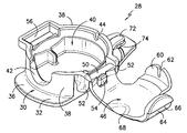
図1および図2は、本発明の態様によるシステム10の斜視図である。本システム10は、固定具28と、固定具28内に収容されるカテーテルコネクタ12とを含む。図1および図2に示したコネクタ12は、背景技術の欄で上述したエピメッド・インターナショナル社製の従来のツイストロック式のスティングレイ(商標)コネクタ(図3参照)である。このコネクタ12は、第1の部分16および第2の部分18を有する本体部14を含む。第2の部分18には近位端ポート20が設けられており、近位端ポート20は、例えば、シリンジ、チューブ、リザーバ(流体貯蔵タンク)、ポンプなどの流体源に連通するための任意のタイプの従来の接続具(fitting)を有している。面示した実施形態では、近位端ポート20は、従来のルアーロック型接続具を有している。図3に特に示すように、コネクタ12の第1の部分16は、カテーテル26を挿入可能であり、かつ挿入されたカテーテル26を摺動自在に受容可能なサイズを有する流路遠位端24を含む。上記に説明したように、図3に示すスティングレイ(商標)コネクタは、ツイストロック式コネクタであり、第1の部分16および第2の部分18を互いに対して回転させることにより、流路遠位端24へのカテーテル26の挿入が可能となる開位置にすることができる。その後、第1の部分16および第2の部分18は、図3に示すような、互いに対して整列する位置に回転して戻される。このとき、カチッという音および触覚により、カテーテル26との完全な係合を確認することができる。
1 and 2 are perspective views of a
添付図面に示したスティングレイ(商標)コネクタは、単に例示を目的としたものであることを理解されたい。本システム10、とりわけ固定具28は、スティングレイ(商標)コネクタに限定されない。詳細については後述するが、本発明の態様によるシステム10は、固定具28を従来の特定の種類のコネクタを受容可能に構成することにより、その従来の特定の種類のカテーテルコネクタを使用することが可能となる。
It should be understood that the Stingray ™ connector shown in the accompanying drawings is for illustrative purposes only. The
添付図面を参照して、固定具28は、下側シェル部材30を含む。図示した実施形態では、下側シェル部材30は、略台形状の形状を有している。しかしながら、これは単に例示を目的としたものであり、下側シェル部材30は、長方形、楕円形、正方形、または任意の他の種類の全体形状および構成を有し得る。下側シェル部材30は、上面36および下面34を有する底板32と、底板32の上面36から立設する外周壁38とを含む。図1および図2から特によく理解できるように、外周壁38は、コネクタ12の周方向の外形に実質的に対応する形状に形成され、コネクタ12を収容可能な内部クレードル空間(interior cradle space)40を画定する。例えば、図示した実施形態では、クレードル空間40は、図3に示したスティングレイ(商標)コネクタの円形形状に適合するように略円形の形状を有する。例えば、コネクタ12の形状が楕円形または長方形である場合、クレードル空間40は、楕円形または長方形に対応する内部形状を有する。
With reference to the accompanying drawings, the
特に図1および図2を参照して、外周壁38はコネクタ本体部14の外周面と周方向に係合し、これにより、コネクタ本体部14と比較的密接するハウジングが形成される。図示した実施形態では、外周壁38に空間や隙間は存在せず、外周壁38はコネクタ本体部14の外周面と実質的に完全に係合している。図示しない別の実施形態では、コネクタ本体部14と密接するクレードル空間40を画定するのに十分な数の位置で、コネクタ本体部14の周囲に係合することができる限り、外周壁38は空間または隙間を有していてもよい。
1 and 2, the outer
外周壁38には、近位端溝42が形成されている。この近位端溝42は、コネクタ12の近位端ポート20の形状に適合する形状および深さを有する。換言すれば、近位端ポート20は、近位端ポート20が外周壁38を貫通する位置において、近位端溝42に挿通され載置される。図5および図6に特によく見えるように、近位端溝42は、その一端から他端まで、近位端ポート20に対して実質的に完全に係合することができる。
A
コネクタ本体部14に対して係合するクレードル空間40により提供される比較的密接するクレードル、並びに近位端ポート20に対して係合する近位端溝42により、コネクタ12は固定具28内に固定的かつ密着的に収容されるので、構成要素間の相対変位はほとんど生じないことを理解されたい。
Due to the relatively close cradle provided by the
外周壁38の遠位端は、コネクタ本体部14の遠位端の外周面を連続的に取り囲む。外周壁38の遠位端の頂面には、コネクタ本体部14の流路遠位端24と軸方向に整合するスロット44が形成されている。図6および図7から容易に理解できるように、このようにして、カテーテル26は、スロット44を通って外周壁38を貫通し、スロット44の内側に位置する流路遠位端24に挿入される。
The distal end of the outer
再び添付図面を概して参照して、固定具28は、ヒンジ線48で下側シェル部材30にヒンジ結合されたカバー部材46を含む。カバー部材46は、図4および図6に示す開位置と、図1、図2、および図5に示す閉位置との間で変位可能である。開位置では、クレードル空間40は、コネクタ12の挿入のためにアクセス可能である。具体的には、コネクタ12の本体部14は、近位端ポート20が近位端溝42を貫通し、かつ流路遠位端24がスロット44と整合するようにして、クレードル空間40に圧入される。カバー部材46は、図1に示した閉位置に変位可能であり、任意の適切な係止機構によって下側シェル部材30に係止される。図示した実施形態では、係止機構は、下側シェル部材30に形成された係止スロット56と、それに係止可能なカバー部材46から突出して形成された係止リップ64とにより構成されている。図5および図6から理解できるように、係止リップ64は、その肩部66を係止スロット56にスライド挿入させるべく内側に撓ませることができ、かつ肩部66が係止スロット56の裏側に対して係合するように外側に撓むことができる程度に可撓性を有する。しかしながら、カバー部材46を下側シェル部材30に対して固定するのに、任意の適切な機械的な係止機構を使用できることを理解されたい。
Referring again generally to the accompanying drawings, the
同様に、本システム10におけるカバー部材46と下側シェル部材30との連結は、任意の特定のヒンジ機構に限定されるものではない。図示した実施形態では、ヒンジ線48は、カバー部材46に設けられたロッド50により画定される。ロッド50は、下側シェル部材30に形成されたフランジ52、52により軸支される。ロッド50はまた、ロッド50を回転のために支持し、フランジ52、52によるロッド50の軸支の維持を確実にする支持部材54内に載置される。繰り返すが、この点に関しては、例えばリビングヒンジなどの任意の適切なヒンジ機構を使用することができる。
Similarly, the connection between the
また、カバー部材46は、本発明の範囲および精神の範囲内で、様々な構成をとることができることを理解されたい。図示した実施形態では、カバー部材46は、その遠位端に、カバー部材46から突出して形成された第1のリップ60を有している。図1に特に示すように、第1のリップ60は、カバー部材46の閉位置において、外周壁38を越えて延在する(すなわち、外周壁38の外側に位置する)。第1のリップ60には、カバー部材46の閉位置において外周壁38のスロット44と整合するスロット62が形成されている。この構成により、カバー部材46の閉位置において、コネクタ本体部14の流路遠位端24に挿入されたカテーテル26の外周面に、第1のリップ60およびスロット62が係合することができる。
It should also be understood that the
特に図4を参照して、肩部66を有する係止リップ(第2のリップ)64は、ヒンジ線48と正反対の位置に設けられており、カバー部材46は、ヒンジ線48と第2のリップ64との間に延在する最近位縁部(proximal-most edge)68を有している。この構成により、図2に特に見えるように、コネクタ本体部14の近位部分および外周壁38の近位部分は、カバー部材46が閉位置にある場合でも露出している。この最近位縁部68により、特にカバー部材46を閉位置から開位置に変位させるときに、カバー部材46の比較的容易な手動操作を可能にする露出縁部が提供される。図示した実施形態では、カバー部材46は、外周壁38に対して、ヒンジ線48、第1のリップ60、および第2のリップ64で当接する略T字状の形状を有している。
With particular reference to FIG. 4, a locking lip (second lip) 64 having a
図示しない別の実施形態では、カバー部材46は、外周壁38の外周面に実質的に完全に係合するように、連続的な円周状のリップを有する。この実施形態では、連続的なリップに、コネクタ12の近位端ポート20に適合する溝が形成される。さらなる別の実施形態では、カバー部材46は、連続的なリップを有する、二枚貝の一方の殻体(half-clam shell)状の形状を有する。
In another embodiment not shown, the
特に、図1、図2、および図7を参照して、固定具28の特定の実施形態は、外周壁38から離間して配置されたカテーテル保持具70を含み得る。例えば、カテーテル保持具70は、固定具28の底板32から離間するように上方に向けて角度付けされた、可撓性を有するまたは付勢された突出体または他のアーム型構造体72を有する。突出体72は、その下側で押圧されたカテーテル26と摩擦係合する高さを有するアンダーカット部(undercut)74を画定する。このカテーテル保持具70は、固定具28に対してカテーテル26を固定するための別の位置を提供する。したがって、不注意により、コネクタ12からカテーテル26が抜去または引き出されるのを防止することができる。
With particular reference to FIGS. 1, 2, and 7, certain embodiments of the
図7を参照して、本発明の態様によるシステム10の実施形態は、本システム10を患者、例えばカテーテル挿入部位に隣接する患者の皮膚75に直接貼り付けるための取付パッド74、例えば発泡体製パッドを含む。この取付パッド74は、任意の適切な材料から作製することができ、底板32の下面に接着される。取付パッド74の底面は、当業者には理解されるように、剥離層で覆われた任意の適切な医療グレードの接着剤を含み得る。
Referring to FIG. 7, an embodiment of a
本発明の態様はまた、独立型の構成要素として、固定具28の様々な実施形態を包含することを理解されたい(例えば、固定具28のクレードル空間40内に収容されるコネクタ12を含まない態様)。この点に関しては、固定具28についての上述の説明は、本発明の態様に係る独立型の固定具に関係している。
It should be understood that aspects of the present invention also include various embodiments of the
本発明について、特定の好適な実施形態に関連付けて説明してきたが、本発明に包含される発明主題は、上述の特定の実施形態に限定されないことを理解されたい。むしろ、本発明の主題は、特許請求の範囲の請求項の範囲および精神の範囲内に含まれる、あらゆる代替形態、改変形態、および均等物を含むものである。 Although the invention has been described in connection with specific preferred embodiments, it is to be understood that the inventive subject matter encompassed by the invention is not limited to the specific embodiments described above. Rather, the subject matter of the invention is intended to embrace all such alternatives, modifications and equivalents that fall within the scope and spirit of the claims.
Claims (8)
周方向全体に連続的に延在して前記本体部を受容するための内部クレードル空間を画定する外周壁を有する下側シェル部材であって、前記外周壁は、前記内部クレードル空間内に前記本体部を収容したときに、前記本体部の外周面と周方向に係合し、かつ前記本体部の前記遠位端の前記外周面を完全に取り囲む、該下側シェル部材と、前記外周壁の近位端に前記外周壁を前記軸方向に貫通して形成され、前記近位端ポートが挿通される近位端溝と、前記外周壁の遠位端に前記流路遠位端と前記軸方向に整合するように前記外周壁を貫通して形成され、前記流路遠位端に挿入されたカテーテルが挿通されるスロットとを含む固定具、および
前記下側シェル部材にヒンジ線でヒンジ結合され、前記カテーテルコネクタを挿入または除去するための開位置と、前記カテーテルコネクタを前記下側シェル部材内に保持するための閉位置との間で変位可能であり、前記閉位置において前記下側シェル部材に解除可能に係止されるカバー部材を含み、
前記外周壁により画定される前記内部クレードル空間内に前記カテーテルコネクタを収容したときに、前記外周壁が前記カテーテルコネクタの前記本体部の前記外周面の周方向全体に対して連続的に係合するように、前記クレードル空間が、前記カテーテルコネクタの前記本体部の形状と一致する形状を有し、かつ前記近位端溝が、前記クレードル空間内に前記カテーテルコネクタを収容したときに前記近位端ポートに対して連続的に係合する形状を有することを特徴とする固定具。 A body portion, a proximal end port formed at a proximal end of the body portion and in communication with a fluid delivery device, a distal end of the body portion formed in axial communication with the proximal end port, A fixture for securing a catheter connector to a patient including a distal end of a flow channel having a size that allows the catheter to pass therethrough,
A lower shell member having an outer peripheral wall that extends continuously in the entire circumferential direction and defines an inner cradle space for receiving the main body, wherein the outer peripheral wall is disposed within the inner cradle space. parts when accommodating a engages the outer peripheral surface in the circumferential direction of the main body portion, and the body portion completely surrounds the outer peripheral surface of the distal end of the lower shell member said, of the outer peripheral wall A proximal end groove formed in the proximal end through the outer peripheral wall in the axial direction and through which the proximal end port is inserted; a flow path distal end and the shaft at a distal end of the outer peripheral wall; A fastener formed through the outer peripheral wall so as to be aligned in a direction and through which a catheter inserted into the distal end of the flow path is inserted, and hinged to the lower shell member by a hinge line For inserting or removing the catheter connector A cover member that is displaceable between an open position and a closed position for holding the catheter connector in the lower shell member and is releasably locked to the lower shell member in the closed position; Including
When the catheter connector is accommodated in the internal cradle space defined by the outer peripheral wall, the outer peripheral wall continuously engages with the entire circumferential direction of the outer peripheral surface of the main body portion of the catheter connector. as such, the cradle space, said catheter connector said to have a shape that matches the shape of the body portion of, and the proximal end groove, said proximal end when accommodating the catheter connector into the cradle space A fixture having a shape that continuously engages with a port .
前記第1のリップは、前記外周壁の前記スロットと前記軸方向に整合するように形成されたスロットを有することを特徴とする請求項1に記載の固定具。 A first lip extending beyond the outer peripheral wall at the closed position of the cover member is formed at a distal end of the cover member;
The fixing device according to claim 1, wherein the first lip has a slot formed to align with the slot of the outer peripheral wall in the axial direction.
前記カバー部材の前記閉位置において前記外周壁を越えて延在し、前記外周壁から延出する係止スロットに解除可能に係止され、かつ前記ヒンジ線の反対側に配置された第2のリップと、
前記カバー部材の前記閉位置において前記外周壁の近位部分が前記カバー部材により覆われず露出するように、前記ヒンジ線と前記第2のリップとの間に延在する最近位縁部とをさらに含むことを特徴とする請求項2に記載の固定具。 The cover member is
A second extending from the outer peripheral wall in the closed position of the cover member, releasably locked in a locking slot extending from the outer peripheral wall, and disposed on the opposite side of the hinge line Lip,
A proximal edge extending between the hinge line and the second lip so that a proximal portion of the outer peripheral wall is exposed without being covered by the cover member in the closed position of the cover member; The fixture according to claim 2 , further comprising:
前記取付パッドが、患者の皮膚に取り付けるための接着性下面を有することを特徴とする請求項1に記載の固定具。 The fixture further includes a mounting pad coupled to a lower surface of the lower shell member;
The fixture of claim 1, wherein the attachment pad has an adhesive bottom surface for attachment to a patient's skin.
Applications Claiming Priority (3)
| Application Number | Priority Date | Filing Date | Title |
|---|---|---|---|
| US14/089,870 US8979805B1 (en) | 2013-11-26 | 2013-11-26 | Catheter connector securement device |
| US14/089,870 | 2013-11-26 | ||
| PCT/IB2014/064866 WO2015079332A1 (en) | 2013-11-26 | 2014-09-26 | Catheter connector securement device |
Publications (3)
| Publication Number | Publication Date |
|---|---|
| JP2016537180A JP2016537180A (en) | 2016-12-01 |
| JP2016537180A5 JP2016537180A5 (en) | 2017-11-02 |
| JP6496324B2 true JP6496324B2 (en) | 2019-04-03 |
Family
ID=51845467
Family Applications (1)
| Application Number | Title | Priority Date | Filing Date |
|---|---|---|---|
| JP2016554931A Active JP6496324B2 (en) | 2013-11-26 | 2014-09-26 | Catheter connector fixture |
Country Status (7)
| Country | Link |
|---|---|
| US (1) | US8979805B1 (en) |
| EP (1) | EP3074077B1 (en) |
| JP (1) | JP6496324B2 (en) |
| AU (1) | AU2014356173B2 (en) |
| CA (1) | CA2930354C (en) |
| MX (1) | MX2016005592A (en) |
| WO (1) | WO2015079332A1 (en) |
Families Citing this family (7)
| Publication number | Priority date | Publication date | Assignee | Title |
|---|---|---|---|---|
| US11207501B2 (en) | 2017-05-30 | 2021-12-28 | Velano Vascular, Inc. | Stabilization devices for vascular access and methods of using the same |
| US11191939B2 (en) | 2017-11-30 | 2021-12-07 | Velano Vascular, Inc. | Stabilizing connector devices for vascular access and methods of using the same |
| JP7058824B2 (en) * | 2018-01-19 | 2022-04-25 | ニプロ株式会社 | Medical connector |
| US10827909B2 (en) * | 2018-02-14 | 2020-11-10 | Marla F. Bashour | Alimentary engagement device |
| JP2022502132A (en) | 2018-09-28 | 2022-01-11 | ベラノ バスキュラー,インコーポレイテッド | Devices and methods for venipuncture with a closed intravenous catheter |
| KR102241228B1 (en) * | 2019-04-18 | 2021-04-16 | 주식회사 유진하이텍 | Catheter fixing apparatus |
| US11738176B2 (en) | 2020-01-10 | 2023-08-29 | Avant-Garde Healthcare Solutions, Inc. | Organizing, anchoring, safety device for peripheral intravenous catheters |
Family Cites Families (14)
| Publication number | Priority date | Publication date | Assignee | Title |
|---|---|---|---|---|
| US4897082A (en) * | 1989-03-20 | 1990-01-30 | Becton, Dickinson And Company | Apparatus for providing a suture tab |
| US6827705B2 (en) * | 1993-03-19 | 2004-12-07 | Venetec International, Inc. | Catheter anchoring system |
| GB2344054B (en) * | 1998-11-28 | 2003-02-19 | Smiths Industries Plc | Catheter retainers and assemblies |
| US6350253B1 (en) | 1999-07-19 | 2002-02-26 | I-Flow Corporation | Catheter for uniform delivery of medication |
| MXPA03009356A (en) | 2001-04-13 | 2004-01-29 | I Flow Corp | Sterile container for medical applications. |
| GB0203713D0 (en) * | 2002-02-16 | 2002-04-03 | Mogg Alan D | Catheter clamp |
| WO2003092781A2 (en) * | 2002-05-01 | 2003-11-13 | Venetec International, Inc. | Medical line securement device |
| EP1528945A2 (en) | 2002-08-15 | 2005-05-11 | Venetec International, Inc. | Catheter securement device |
| EP1855738B1 (en) * | 2005-03-10 | 2013-05-08 | Custom Medical Applications, Inc. | Catheter connection hub |
| ES2895905T3 (en) * | 2006-01-12 | 2022-02-23 | Venetec Int Inc | Universal catheter fixation device |
| WO2008151047A1 (en) * | 2007-06-01 | 2008-12-11 | Medical Device Group, Inc. | Universal catheter securement device |
| US8211064B2 (en) * | 2008-01-11 | 2012-07-03 | Centurion Medical Products Corporation | Catheter securement device |
| US8617115B2 (en) * | 2010-05-17 | 2013-12-31 | Clay Kennard | Apparatus for umbilical catheter |
| ITTO20110730A1 (en) * | 2011-08-04 | 2013-02-05 | Filippo Gugliotta | PROTECTION AND HOUSING SYSTEM, IN PARTICULAR FOR A DEVICE FOR THE ADMINISTRATION OF THERAPIES TO A PATIENT. |
-
2013
- 2013-11-26 US US14/089,870 patent/US8979805B1/en active Active
-
2014
- 2014-09-26 CA CA2930354A patent/CA2930354C/en active Active
- 2014-09-26 EP EP14792886.5A patent/EP3074077B1/en active Active
- 2014-09-26 MX MX2016005592A patent/MX2016005592A/en active IP Right Grant
- 2014-09-26 WO PCT/IB2014/064866 patent/WO2015079332A1/en active Application Filing
- 2014-09-26 AU AU2014356173A patent/AU2014356173B2/en active Active
- 2014-09-26 JP JP2016554931A patent/JP6496324B2/en active Active
Also Published As
| Publication number | Publication date |
|---|---|
| CA2930354A1 (en) | 2015-06-04 |
| CA2930354C (en) | 2021-09-21 |
| EP3074077A1 (en) | 2016-10-05 |
| US8979805B1 (en) | 2015-03-17 |
| EP3074077B1 (en) | 2019-11-20 |
| AU2014356173B2 (en) | 2018-11-08 |
| WO2015079332A1 (en) | 2015-06-04 |
| JP2016537180A (en) | 2016-12-01 |
| MX2016005592A (en) | 2016-07-21 |
| AU2014356173A1 (en) | 2016-05-19 |
Similar Documents
| Publication | Publication Date | Title |
|---|---|---|
| JP6496324B2 (en) | Catheter connector fixture | |
| JP6929323B2 (en) | Lure fixed device | |
| US11541172B2 (en) | Infusion set with safety device | |
| RU2468828C2 (en) | Cannula and introduction device | |
| ES2945732T3 (en) | Device for the sustained supply of a therapeutic liquid | |
| US11167113B2 (en) | Two-piece catheter securement system and method for using same | |
| CA2926028C (en) | Catheter securement device | |
| US20070213673A1 (en) | Infusion Device Having Offset Flow Path | |
| JP2011507555A5 (en) | ||
| US9694132B2 (en) | Insertion device for insertion set | |
| JP2016537180A5 (en) | ||
| DK2983734T3 (en) | INFUSION KIT WITH IMPROVED Borehole Configuration | |
| JP2017164257A (en) | Catheter retainer | |
| JP5995812B2 (en) | Treatment fluid injection system |
Legal Events
| Date | Code | Title | Description |
|---|---|---|---|
| A521 | Request for written amendment filed |
Free format text: JAPANESE INTERMEDIATE CODE: A523 Effective date: 20170918 |
|
| A621 | Written request for application examination |
Free format text: JAPANESE INTERMEDIATE CODE: A621 Effective date: 20170918 |
|
| A131 | Notification of reasons for refusal |
Free format text: JAPANESE INTERMEDIATE CODE: A131 Effective date: 20180807 |
|
| A521 | Request for written amendment filed |
Free format text: JAPANESE INTERMEDIATE CODE: A523 Effective date: 20181026 |
|
| TRDD | Decision of grant or rejection written | ||
| A01 | Written decision to grant a patent or to grant a registration (utility model) |
Free format text: JAPANESE INTERMEDIATE CODE: A01 Effective date: 20190212 |
|
| A61 | First payment of annual fees (during grant procedure) |
Free format text: JAPANESE INTERMEDIATE CODE: A61 Effective date: 20190308 |
|
| R150 | Certificate of patent or registration of utility model |
Ref document number: 6496324 Country of ref document: JP Free format text: JAPANESE INTERMEDIATE CODE: R150 |
|
| R250 | Receipt of annual fees |
Free format text: JAPANESE INTERMEDIATE CODE: R250 |
|
| R250 | Receipt of annual fees |
Free format text: JAPANESE INTERMEDIATE CODE: R250 |
|
| R250 | Receipt of annual fees |
Free format text: JAPANESE INTERMEDIATE CODE: R250 |