JP6496262B2 - Ball, in particular soccer ball, and method of manufacturing the ball - Google Patents
Ball, in particular soccer ball, and method of manufacturing the ball Download PDFInfo
- Publication number
- JP6496262B2 JP6496262B2 JP2016044101A JP2016044101A JP6496262B2 JP 6496262 B2 JP6496262 B2 JP 6496262B2 JP 2016044101 A JP2016044101 A JP 2016044101A JP 2016044101 A JP2016044101 A JP 2016044101A JP 6496262 B2 JP6496262 B2 JP 6496262B2
- Authority
- JP
- Japan
- Prior art keywords
- shell
- void
- panels
- ball
- filling
- Prior art date
- Legal status (The legal status is an assumption and is not a legal conclusion. Google has not performed a legal analysis and makes no representation as to the accuracy of the status listed.)
- Active
Links
- 238000004519 manufacturing process Methods 0.000 title claims description 26
- 239000000463 material Substances 0.000 claims description 155
- 239000011800 void material Substances 0.000 claims description 78
- 238000000034 method Methods 0.000 claims description 69
- 239000000945 filler Substances 0.000 claims description 47
- 239000007788 liquid Substances 0.000 claims description 16
- 229920002635 polyurethane Polymers 0.000 claims description 11
- 239000004814 polyurethane Substances 0.000 claims description 11
- 229920001296 polysiloxane Polymers 0.000 claims description 7
- 230000003287 optical effect Effects 0.000 claims description 5
- 239000011257 shell material Substances 0.000 description 77
- 239000010985 leather Substances 0.000 description 16
- 229920001971 elastomer Polymers 0.000 description 13
- 239000002649 leather substitute Substances 0.000 description 10
- 239000000853 adhesive Substances 0.000 description 8
- 230000001070 adhesive effect Effects 0.000 description 8
- 230000003655 tactile properties Effects 0.000 description 7
- 230000003068 static effect Effects 0.000 description 5
- XLYOFNOQVPJJNP-UHFFFAOYSA-N water Substances O XLYOFNOQVPJJNP-UHFFFAOYSA-N 0.000 description 5
- 239000011324 bead Substances 0.000 description 3
- 239000006260 foam Substances 0.000 description 3
- 230000002787 reinforcement Effects 0.000 description 3
- 238000007373 indentation Methods 0.000 description 2
- 238000001746 injection moulding Methods 0.000 description 2
- 230000035515 penetration Effects 0.000 description 2
- 229920003023 plastic Polymers 0.000 description 2
- 239000004033 plastic Substances 0.000 description 2
- 230000008092 positive effect Effects 0.000 description 2
- 230000003014 reinforcing effect Effects 0.000 description 2
- 238000009958 sewing Methods 0.000 description 2
- 239000002759 woven fabric Substances 0.000 description 2
- 239000004677 Nylon Substances 0.000 description 1
- 230000004913 activation Effects 0.000 description 1
- 238000004026 adhesive bonding Methods 0.000 description 1
- 230000015572 biosynthetic process Effects 0.000 description 1
- 239000003086 colorant Substances 0.000 description 1
- 238000010276 construction Methods 0.000 description 1
- 238000005520 cutting process Methods 0.000 description 1
- 239000006185 dispersion Substances 0.000 description 1
- 238000005516 engineering process Methods 0.000 description 1
- 239000006261 foam material Substances 0.000 description 1
- 238000010438 heat treatment Methods 0.000 description 1
- 238000002347 injection Methods 0.000 description 1
- 239000007924 injection Substances 0.000 description 1
- 238000005304 joining Methods 0.000 description 1
- 229920000126 latex Polymers 0.000 description 1
- 239000004816 latex Substances 0.000 description 1
- 239000000314 lubricant Substances 0.000 description 1
- 230000013011 mating Effects 0.000 description 1
- 230000003278 mimic effect Effects 0.000 description 1
- 229920001778 nylon Polymers 0.000 description 1
- 239000013307 optical fiber Substances 0.000 description 1
- 230000000149 penetrating effect Effects 0.000 description 1
- 239000002985 plastic film Substances 0.000 description 1
- 238000003825 pressing Methods 0.000 description 1
- 230000005855 radiation Effects 0.000 description 1
- 239000011347 resin Substances 0.000 description 1
- 229920005989 resin Polymers 0.000 description 1
- 238000004804 winding Methods 0.000 description 1
Images


Classifications
-
- A—HUMAN NECESSITIES
- A63—SPORTS; GAMES; AMUSEMENTS
- A63B—APPARATUS FOR PHYSICAL TRAINING, GYMNASTICS, SWIMMING, CLIMBING, OR FENCING; BALL GAMES; TRAINING EQUIPMENT
- A63B45/00—Apparatus or methods for manufacturing balls
-
- A—HUMAN NECESSITIES
- A63—SPORTS; GAMES; AMUSEMENTS
- A63B—APPARATUS FOR PHYSICAL TRAINING, GYMNASTICS, SWIMMING, CLIMBING, OR FENCING; BALL GAMES; TRAINING EQUIPMENT
- A63B41/00—Hollow inflatable balls
- A63B41/08—Ball covers; Closures therefor
-
- A—HUMAN NECESSITIES
- A63—SPORTS; GAMES; AMUSEMENTS
- A63B—APPARATUS FOR PHYSICAL TRAINING, GYMNASTICS, SWIMMING, CLIMBING, OR FENCING; BALL GAMES; TRAINING EQUIPMENT
- A63B41/00—Hollow inflatable balls
- A63B41/08—Ball covers; Closures therefor
- A63B41/085—Closures
-
- A—HUMAN NECESSITIES
- A63—SPORTS; GAMES; AMUSEMENTS
- A63B—APPARATUS FOR PHYSICAL TRAINING, GYMNASTICS, SWIMMING, CLIMBING, OR FENCING; BALL GAMES; TRAINING EQUIPMENT
- A63B41/00—Hollow inflatable balls
- A63B41/10—Bladder and cover united
-
- A—HUMAN NECESSITIES
- A63—SPORTS; GAMES; AMUSEMENTS
- A63B—APPARATUS FOR PHYSICAL TRAINING, GYMNASTICS, SWIMMING, CLIMBING, OR FENCING; BALL GAMES; TRAINING EQUIPMENT
- A63B43/00—Balls with special arrangements
- A63B43/004—Balls with special arrangements electrically conductive, e.g. for automatic arbitration
-
- A—HUMAN NECESSITIES
- A63—SPORTS; GAMES; AMUSEMENTS
- A63B—APPARATUS FOR PHYSICAL TRAINING, GYMNASTICS, SWIMMING, CLIMBING, OR FENCING; BALL GAMES; TRAINING EQUIPMENT
- A63B43/00—Balls with special arrangements
- A63B43/06—Balls with special arrangements with illuminating devices ; with reflective surfaces
-
- A—HUMAN NECESSITIES
- A63—SPORTS; GAMES; AMUSEMENTS
- A63B—APPARATUS FOR PHYSICAL TRAINING, GYMNASTICS, SWIMMING, CLIMBING, OR FENCING; BALL GAMES; TRAINING EQUIPMENT
- A63B2225/00—Miscellaneous features of sport apparatus, devices or equipment
- A63B2225/01—Special aerodynamic features, e.g. airfoil shapes, wings or air passages
-
- A—HUMAN NECESSITIES
- A63—SPORTS; GAMES; AMUSEMENTS
- A63B—APPARATUS FOR PHYSICAL TRAINING, GYMNASTICS, SWIMMING, CLIMBING, OR FENCING; BALL GAMES; TRAINING EQUIPMENT
- A63B2225/00—Miscellaneous features of sport apparatus, devices or equipment
- A63B2225/50—Wireless data transmission, e.g. by radio transmitters or telemetry
- A63B2225/54—Transponders, e.g. RFID
-
- A—HUMAN NECESSITIES
- A63—SPORTS; GAMES; AMUSEMENTS
- A63B—APPARATUS FOR PHYSICAL TRAINING, GYMNASTICS, SWIMMING, CLIMBING, OR FENCING; BALL GAMES; TRAINING EQUIPMENT
- A63B2225/00—Miscellaneous features of sport apparatus, devices or equipment
- A63B2225/74—Miscellaneous features of sport apparatus, devices or equipment with powered illuminating means, e.g. lights
-
- A—HUMAN NECESSITIES
- A63—SPORTS; GAMES; AMUSEMENTS
- A63B—APPARATUS FOR PHYSICAL TRAINING, GYMNASTICS, SWIMMING, CLIMBING, OR FENCING; BALL GAMES; TRAINING EQUIPMENT
- A63B2243/00—Specific ball sports not provided for in A63B2102/00 - A63B2102/38
- A63B2243/0025—Football
-
- A—HUMAN NECESSITIES
- A63—SPORTS; GAMES; AMUSEMENTS
- A63B—APPARATUS FOR PHYSICAL TRAINING, GYMNASTICS, SWIMMING, CLIMBING, OR FENCING; BALL GAMES; TRAINING EQUIPMENT
- A63B2243/00—Specific ball sports not provided for in A63B2102/00 - A63B2102/38
- A63B2243/0066—Rugby; American football
-
- B—PERFORMING OPERATIONS; TRANSPORTING
- B33—ADDITIVE MANUFACTURING TECHNOLOGY
- B33Y—ADDITIVE MANUFACTURING, i.e. MANUFACTURING OF THREE-DIMENSIONAL [3-D] OBJECTS BY ADDITIVE DEPOSITION, ADDITIVE AGGLOMERATION OR ADDITIVE LAYERING, e.g. BY 3-D PRINTING, STEREOLITHOGRAPHY OR SELECTIVE LASER SINTERING
- B33Y10/00—Processes of additive manufacturing
-
- B—PERFORMING OPERATIONS; TRANSPORTING
- B33—ADDITIVE MANUFACTURING TECHNOLOGY
- B33Y—ADDITIVE MANUFACTURING, i.e. MANUFACTURING OF THREE-DIMENSIONAL [3-D] OBJECTS BY ADDITIVE DEPOSITION, ADDITIVE AGGLOMERATION OR ADDITIVE LAYERING, e.g. BY 3-D PRINTING, STEREOLITHOGRAPHY OR SELECTIVE LASER SINTERING
- B33Y80/00—Products made by additive manufacturing
Description
本発明は、ボール、特にサッカーボール、およびそのようなボールを製造する方法に関する。 The present invention relates to a ball, in particular a soccer ball, and a method of manufacturing such a ball.
ボール、特にサッカーなどのボールスポーツ用ボールは、通常、皮革もしくは合成皮革の単片またはほとんどがプラスチックから製造されるパネルから縫い合わされ、ブラダ上または補強のためにブラダ上に配置されたカーカス上に糊付けされる。後者の種類のボールは、積層ボールとも呼ばれる。 Balls, especially ball sports balls such as soccer, are usually stitched from panels made of plastic or mostly leather or synthetic leather, on the bladder or on the carcass placed on the bladder for reinforcement It is glued. The latter type of ball is also called a laminated ball.
縫いボールは、複数の皮革または合成皮革の部片から製造され、これらの部片の縁は、内向きに折り畳まれ、針で縫い合わせられる。皮革または合成皮革の部片のジオメトリの対応する選択により、ほぼ球形の形状が、縫い合わせることによってもたらされる。補強のために、織布が、通常、皮革または合成皮革の部片の裏側に糊付けされる。必要な気密性をもたらす、たとえばゴム製のブラダが、ほとんどの場合、手縫いボール内に挿入される。ブラダはまた、ボールを膨張させるための弁も備える。ブラダと皮革または合成皮革の部片の間には、織布または1つまたは複数の円周方向糸から作製されたカーカスが、ブラダの補強および保護のために配置され得る。 Sewing balls are manufactured from a plurality of leather or synthetic leather pieces, the edges of which are folded inward and stitched together with a needle. With a corresponding selection of the leather or synthetic leather piece geometry, a substantially spherical shape is brought about by stitching. For reinforcement, a woven fabric is usually glued to the back side of a piece of leather or synthetic leather. For example, a rubber bladder, which provides the necessary tightness, is most often inserted into a hand-sewn ball. The bladder also includes a valve for inflating the ball. Between the bladder and the piece of leather or synthetic leather, a carcass made from woven fabric or one or more circumferential threads can be placed for bladder reinforcement and protection.
そのような縫い合わされたボールでは、皮革または合成皮革の部片の縁は、内側に押し付けて折り畳まれ、こうして皮革または合成皮革の隣接する、すなわち接している部片と共に縫われる。このように、溝の形態のシームが、ボールの外側の、皮革または合成皮革の隣り合う部片間に形成される。そのようなシームは、一般的に、約2.5mmの上部(すなわちボールの中心から外方を向く側)の幅、および約2.0mmの深さを含む。 In such stitched balls, the edges of the leather or synthetic leather pieces are folded inwardly and thus sewn together with the adjacent or abutting pieces of leather or synthetic leather. In this way, a seam in the form of a groove is formed between adjacent pieces of leather or synthetic leather outside the ball. Such seams typically include a width of the top (ie, the side facing away from the center of the ball) of about 2.5 mm and a depth of about 2.0 mm.
縫い合わされたボールのシームが、抗力を低減することによって空気力学的特性に良い影響を与え、それにしたがってさらに遠い飛距離を可能にすることが証明されている。その原因として、飛行しているボールの表面上の乱気流が小さいことが考えられる。さらに、シームは、ボールの把持特性に貢献し、すなわちボールをより容易に把持および制御することができる。 It has been demonstrated that stitched ball seams have a positive impact on aerodynamic properties by reducing drag, thus allowing for farther distances. A possible cause is that the turbulence on the surface of the flying ball is small. In addition, the seam contributes to the gripping characteristics of the ball, i.e., the ball can be gripped and controlled more easily.
しかし、ボールは三次元形状を有するので、これを機械によって縫うことができず、手によって縫われる必要がある。その欠点は、そのような手縫いボールは、一方では品質に影響を与え、他方では重量、サイズ、球形状、飛行および把持特性の変動を示し得る、製造における大きな変動を受けることである。手縫いボールの別の欠点は、その製造によってかなりの時間がかかることである。 However, since the ball has a three-dimensional shape, it cannot be sewn by a machine and needs to be sewn by hand. The disadvantage is that such hand-sewn balls are subject to significant variations in manufacturing that can, on the one hand, affect quality and on the other hand show variations in weight, size, sphere shape, flight and gripping characteristics. Another disadvantage of hand-sewn balls is that it takes a considerable amount of time to manufacture.
これらの欠点は、部分的には、積層ボールによって克服され、その理由は、そのパネルをこれらのボールになるように手で縫う必要がないためである。手縫いボールに対する製造の通常の変動は、したがって、より少ない程度でボールに見出される。さらに、積層ボールは、少なくとも部分的には、対応する機械によって製造され得る。その結果、および手で縫うことを解消することにより、積層ボールは、本質的により速く製造され得る。 These disadvantages are partly overcome by laminated balls because the panels do not need to be sewn by hand to be these balls. The normal manufacturing variations for hand-sewn balls are therefore found to a lesser extent in the balls. Furthermore, the laminated balls can be manufactured at least in part by corresponding machines. As a result, and by eliminating the need to sew by hand, laminated balls can be manufactured essentially faster.
しかし、異なるパネル間の溝がより低い深さ(通常は約1mm)を含むため、積層ボールの飛行および把持特性は劣化する。さらに、積層ボールの従来の製造方法は、この溝のジオメトリ(すなわち深さ、幅、断面プロファイルなど)および表面特性(すなわちたとえば静摩擦、触覚性、粗度など)に影響を与えることができず、またはできたとしても限定される。 However, because the grooves between the different panels contain lower depths (usually about 1 mm), the flight and grip characteristics of the laminated ball are degraded. Furthermore, conventional manufacturing methods for laminated balls cannot affect the geometry (i.e. depth, width, cross-sectional profile, etc.) and surface properties (i.e. static friction, tactile properties, roughness, etc.) of this groove, Or even if it is possible.
米国特許第6,398,894B1号は、バスケットボールを製造する方法であって、とりわけ以下のステップ:(a)ゴム材料のシートを供給するステップと、(b)ゴム材料を折り畳み、圧縮し、切断してゴム材料をブラダに作製するステップと、(c)弁をブラダ内に装着するステップと、(d)ブラダを空気で膨張させ、ブラダを硬化させるステップと、膨張されたブラダ上に少なくとも1本の糸を巻き付けるステップと、(f)ゴムアーチをラグ層の表面上に糊付けするステップと、(g)隣り合うゴムシート間の各々の接合部に溝を作製するステップと、(h)隣り合うゴムシートの各々の接合部にゴムシートより薄く狭いストリップを結合させるステップと、(i)複数の突起するリブが中に画定された型内で、比較的大きい複数のゴムシートをストリップと共に加熱し硬化させてバスケットボールを作製するステップとを含み、それによってバスケットボールは、2つの傾いた壁が中に画定された、複数の比較的凹状のくぼみを有する、方法を示している。 U.S. Pat. No. 6,398,894 B1 is a method of manufacturing basketball, which includes, inter alia, the following steps: (a) supplying a sheet of rubber material; (b) folding, compressing and cutting the rubber material. Producing a rubber material in the bladder, (c) mounting the valve in the bladder, (d) inflating the bladder with air and curing the bladder, and at least one on the inflated bladder Winding a string of books; (f) gluing a rubber arch on the surface of the lug layer; (g) creating a groove at each joint between adjacent rubber sheets; and (h) adjoining. Bonding a thin and narrow strip than the rubber sheet to each joint of the rubber sheet; and (i) relatively large within a mold having a plurality of protruding ribs defined therein Heating and curing a number of rubber sheets with the strip to produce a basketball, whereby the basketball has a plurality of relatively concave indentations with two inclined walls defined therein, Show.
米国特許第3,887,416号は、皮革で覆われたサッカーボールを製造する方法に関する。サッカーボールは、ナイロンコードが巻き付けられ、ゴムの層で覆われ、これらすべて従来のものであるブラダを得て、これを、シームにおけるストリップ、シームに隣り合う構築領域、および各々の端部にある成形された要素を含む、いくつかのゴムセグメントで覆うことによって作製される。 U.S. Pat. No. 3,887,416 relates to a method of manufacturing a soccer ball covered with leather. The soccer ball is wrapped with a nylon cord and covered with a layer of rubber to get these all conventional bladders, which are on the strip at the seam, the construction area adjacent to the seam, and at each end Made by covering with several rubber segments, including molded elements.
米国特許第5,541,662号は、スポーツボール、および対応する製造方法に関する。膨張可能なチューブが、薄いゴムポケットによって形成された上部層内に挿入され、この薄いゴムポケットは、結合剤の溶液が上部層、およびチューブと上部層の間に配置された無機潤滑剤を通って浸透することを可能にしない材料から製造される。 U.S. Pat. No. 5,541,662 relates to a sports ball and a corresponding manufacturing method. An inflatable tube is inserted into the upper layer formed by the thin rubber pocket, which passes through the upper layer and an inorganic lubricant that is placed between the tube and the upper layer. Manufactured from a material that does not allow it to penetrate.
欧州特許第1080745B2号は、ブラダが皮革の複数の部片上に配置された積層ボールに関し、皮革の部片は、不連続部において互いに結合される。皮革の部片は、直接的に互いに結合され、それにより、皮革の隣り合う部片をブラダにあてるとき、皮革の部片間には空隙は存在しない。 EP 1080745B2 relates to a laminated ball in which a bladder is arranged on a plurality of pieces of leather, the pieces of leather being joined together at discontinuities. The pieces of leather are directly joined together so that there are no gaps between the pieces of leather when adjacent pieces of leather are applied to the bladder.
米国特許第8,574,104号は、膨張可能なスポーツボール構造、およびその製造方法に関する。膨張可能なスポーツボール構造は、内側ブラダ、補強カーカス、および外部材料層を備える。補強カーカスは、内側ブラダの表面を覆い、糸が巻き付けられた層を有する。糸が巻き付けられた層の一部は、補強カーカス内に埋め込まれ、内側ブラダへの締め付け力をもたらし、糸が巻かれた層のわずかな残りの部分は、補強されたカーカスの外側表面上に露出され得る。 U.S. Pat. No. 8,574,104 relates to an inflatable sports ball structure and a method for manufacturing the same. The inflatable sports ball structure includes an inner bladder, a reinforcing carcass, and an outer material layer. The reinforcing carcass has a layer that covers the surface of the inner bladder and is wound with yarn. A portion of the yarn wound layer is embedded in the reinforced carcass, providing a clamping force to the inner bladder, and a small portion of the yarn wound layer is on the outer surface of the reinforced carcass. Can be exposed.
したがって、本発明の主な目的は、ボール、特にサッカーボールであって、一方では比較的速く、容易に、またコスト効果高く製造され、他方では、手縫いボールのものに近い非常に良好な飛行および把持特性を含むが、手縫いボールの通常の品質変動を有さないボールを提供することである。さらに、ボールの飛行および把持特性は、個々に調整可能でなければならない。 The main object of the present invention is therefore a ball, in particular a soccer ball, which on the one hand is relatively fast, easily and cost-effectively manufactured and on the other hand a very good flight and close to that of a hand-sewn ball. It is to provide a ball that includes gripping characteristics but does not have the normal quality variation of hand-sewn balls. Furthermore, the flight and grip characteristics of the ball must be individually adjustable.
本発明の第1の態様によれば、上記で述べた問題は、ボール、特にサッカーボールであって、(a.)複数のパネルをその外側に備えたシェルを備え、(b.)パネルは、少なくとも2つの隣り合うパネル間に少なくとも1つの空隙が存在するように配置され、(c.)少なくとも1つの空隙は、充填材料によって少なくとも部分的に充填される、ボールによって解決される。 According to a first aspect of the present invention, the above mentioned problem is a ball, in particular a soccer ball, comprising: (a.) A shell with a plurality of panels on its outside; (b.) Arranged such that there is at least one void between at least two adjacent panels, and (c.) The at least one void is solved by a ball that is at least partially filled with a filling material.
本発明によれば、こうしてボールは、故に部分的に、2つのパネル間に少なくとも1つの空隙を含む。本発明による空隙は、パネルがその空隙の領域内では接触せず、自由空間がそれぞれのパネル間に形成されるものとして理解される。空隙が、本発明による充填材料によって充填されない場合、パネルがその上に配置されたシェルを、空隙を通して見ることができ、この場合パネルはその上に配置されている。しかし、本発明によれば、2つのパネルが1つの領域内で空隙を形成し、別の領域で互いに接触することを排除できない。 According to the invention, the ball thus thus partially comprises at least one gap between the two panels. A void according to the invention is understood as a panel is not in contact within the region of the void, and a free space is formed between each panel. If the void is not filled with the filling material according to the invention, the shell on which the panel is arranged can be seen through the void, in which case the panel is arranged thereon. However, according to the present invention, it cannot be excluded that two panels form a gap in one region and contact each other in another region.
本発明によるボールは、パネルが、たとえば適切なシェル(ブラダまたはカーカスで補強されたブラダ)上に糊付けられるため、比較的速く、容易に、またコスト効果高く製造され得る。これはまた、適切な機械によって自動的に行われ得る。それと同時に、空隙が少なくとも2つのパネル間に形成され、充填材料によって充填される。こうして、充填された空隙は、手縫いボールのシームを模倣し、ボールの空気力学的特性に良い影響を与える。充填材料は、それぞれの空隙内に挿入可能であるように規定される。したがって、製造されたボールの特定の空気力学的特性は、影響可能であり、非常に特異的に決定可能である。それぞれの空隙の高さおよび/または幅は、個々に決定可能である。 The balls according to the invention can be manufactured relatively fast, easily and cost-effectively, since the panels are glued on eg a suitable shell (bladder or carcass reinforced bladder). This can also be done automatically by a suitable machine. At the same time, a void is formed between at least two panels and is filled with a filling material. Thus, the filled void mimics the seam of a hand-sewn ball and has a positive effect on the aerodynamic characteristics of the ball. The filling material is defined such that it can be inserted into the respective void. Thus, the specific aerodynamic characteristics of the manufactured ball can be influenced and can be determined very specifically. The height and / or width of each void can be determined individually.
一方で充填された空隙のジオメトリ(すなわち、たとえば深さ、幅、断面プロファイル、曲率など)および表面特性(すなわち、たとえば静摩擦、触覚性、粗度など)は、充填材料の量によって、他方では充填材料の品質によって選択的に影響され得る。たとえば、特に滑り止め充填材料が、ボールの把持特性を改良するために使用され得る。 On the one hand the geometry of the filled void (ie depth, width, cross-sectional profile, curvature etc.) and surface properties (ie eg static friction, tactile feel, roughness etc.) depend on the amount of filling material and on the other hand It can be selectively influenced by the quality of the material. For example, non-slip filling materials can be used in particular to improve the gripping characteristics of the ball.
充填された空隙の深さは、好ましくは少なくとも1mm、好ましくは少なくとも1.5mm、より好ましくは少なくとも2mmである。充填材料の量は、充填された空隙の望ましい最小深さが維持されるように影響可能である。 The depth of the filled void is preferably at least 1 mm, preferably at least 1.5 mm, more preferably at least 2 mm. The amount of filler material can be influenced such that the desired minimum depth of the filled void is maintained.
さらに、本発明によるボールの空隙は、さまざまなボール間の製造における変動(したがって空気力性および触覚性に関する変動)を最小限に低減するために、機械によって自動的に充填されてもよい。したがって、手縫いボールとは異なり、「シーム」(すなわち充填された空隙)は、いかなるボールにおいても同じ断面を常に含む。 Furthermore, the ball gaps according to the present invention may be filled automatically by the machine in order to minimize the variations in the production between the various balls (and thus the variations in aerodynamic and tactile properties). Thus, unlike hand-sewn balls, a “seam” (ie, a filled void) always includes the same cross section in any ball.
従来の積層ボールとは対照的に、さらにより良好な飛行および把持特性を得るために、一方では製造における変動がさらに低減され、他方では、「シーム」のジオメトリおよび表面品質が特異的に設定され得る。たとえば、隣り合うパネルが互いに接触する従来の積層ボールに可能であるものよりもかなり広い幅の「シーム」が、得られ得る。 In contrast to conventional laminated balls, to obtain even better flight and gripping properties, on the one hand the variability in manufacturing is further reduced, and on the other hand the geometry and surface quality of the “seam” is set specifically. obtain. For example, a “seam” can be obtained that is much wider than what is possible with conventional laminated balls where adjacent panels contact each other.
充填材料は、シェルの外側が空隙の内側で完全に覆われるように空隙を充填する。したがって、下にあるシェルは保護され得、水の浸透が防止される。手縫いボールとは異なり、本発明によるボールは水を吸収しない。 The filling material fills the void so that the outside of the shell is completely covered inside the void. Thus, the underlying shell can be protected and water penetration is prevented. Unlike hand-sewn balls, the balls according to the invention do not absorb water.
充填材料は、硬化前は液体である硬化された充填材料であってもよい。液体充填材料は、容易に処理され得、空隙を非常に良好に充填し、これは、充填材料が空隙の形に嵌合し、いわばこれに流入するためである。その結果、ボールは、特に防水性になる。 The filler material may be a cured filler material that is liquid prior to curing. The liquid filling material can be easily handled and fills the voids very well because the filling material fits in the shape of the voids, so to speak. As a result, the ball is particularly waterproof.
充填材料は、ポリウレタンまたはシリコーンを含んでもよい。これらの材料は、処理が容易であり、有利な表面特性、特に、高い静摩擦を含み、高レベルの防水性をもたらす。特に、ポリウレタンの材料特性、たとえば粘度は、特に良好に調整可能である。ポリウレタンはまた、周囲材料、特にパネルおよびシェルの材料に対して高い親和性も含む。あるいは、他の材料、たとえば樹脂系を充填材料として使用することもできる。 The filling material may comprise polyurethane or silicone. These materials are easy to process and include advantageous surface properties, in particular high static friction and provide a high level of waterproofness. In particular, the material properties of polyurethane, such as the viscosity, can be adjusted particularly well. Polyurethanes also contain a high affinity for surrounding materials, especially panel and shell materials. Alternatively, other materials such as resin systems can be used as the filling material.
充填材料は、少なくとも1つの発光要素を含んでもよい。したがってボールは、低光量状態(たとえば夕方)でもはっきりと見ることができる。さらに、製造されたボールの個別化が、発光要素の特定の選択色によって達成され得る。たとえば、発光要素は、特定のクラブ色でこうして選択されてよい。LEDもしくはマイクロLED、またはOLEDである発光要素が、たとえば、充填材料に埋め込まれ得る。充填材料は、特に暗闇の中で発光する蛍光性または化学発光性材料でよい。埋め込まれたさまざまな発光要素を有するさまざまなボールが販売され得るビジネスモデルもまた、存在し得る。故に、顧客は、特定の色の発光ボールを購入することが可能である。 The filling material may include at least one light emitting element. Therefore, the ball can be clearly seen even in a low light state (for example, in the evening). Furthermore, individualization of the manufactured balls can be achieved by a specific selected color of the light emitting elements. For example, the light emitting elements may thus be selected with a particular club color. A light emitting element that is an LED or a micro LED, or an OLED can be embedded in a filler material, for example. The filling material may be a fluorescent or chemiluminescent material that emits light in the dark. There may also be a business model in which different balls with different light emitting elements embedded can be sold. Therefore, the customer can purchase a light emitting ball of a specific color.
情報を読み取ることができるディスプレイが、充填材料内にさらに埋め込まれ得る。たとえば、そのような情報は、測定されたシュート速度、衝撃力、飛行高さまたは競技時間に関する標示であってもよい。そのような標示の測定のためのセンサが、ボールの内側に配置され得る。あるいは、情報は、充填材料内に配置されたディスプレイによって、たとえばタッチスクリーンによって入力され得る。 A display capable of reading information may be further embedded within the filler material. For example, such information may be an indication of measured shoot speed, impact force, flight height or playing time. Sensors for measuring such indications can be arranged inside the ball. Alternatively, the information can be entered by a display placed in the filling material, for example by a touch screen.
充填材料はまた、通常、ディスプレイとして形成され得る。故に、充填材料が、測定された情報に応じてその色を変更することが可能である。したがって、充填材料は、測定されたシュート速度またはシュート力に応じてさまざまな色で発光することが考えられる。したがって、充填材料は、第1のシュート力範囲に対して第1の色で、第2のシュート力範囲に対して第2の色で、第3のシュート力範囲に対して第3の色で発光してもよい。 The filler material can also typically be formed as a display. Thus, it is possible for the filling material to change its color depending on the measured information. Therefore, it is conceivable that the filling material emits light in various colors depending on the measured shoot speed or shoot force. Thus, the filling material is in the first color for the first shoot force range, in the second color for the second shoot force range, and in the third color for the third shoot force range. It may emit light.
充填材料は、少なくとも1つの電子要素を備えてもよい。たとえば、電子要素は、ボールについての情報をそれによって読み取ることができるRFIDまたはNFCタグであってもよい。 The filling material may comprise at least one electronic element. For example, the electronic element may be an RFID or NFC tag by which information about the ball can be read.
充填材料は、空隙の断面積を約50%以上充填してもよい。このように、空隙は良好に閉鎖され、浸透する水に対して保護される。他方では、空隙の断面の充填されていない部分は、良好な飛行および把持特性を達成するために依然として十分な深さである。 The filling material may fill the cross-sectional area of the voids by about 50% or more. In this way, the voids are well closed and protected against penetrating water. On the other hand, the unfilled portion of the void cross-section is still deep enough to achieve good flight and gripping characteristics.
充填材料がパネルの面取りされた表面間の領域内に延びるように、空隙が充填材料で充填される場合、利点となる。充填材料の高さは、好ましくはパネルの横方向縁部の高さより高く、パネルの全高さより低い。面取りされた表面の各々は、パネルの横方向縁とパネルの外側表面間を延びる。充填材料の高さが、パネルの横方向縁の高さよりわずかだけ高い場合、特に有利である。面取りされる代わりに、表面は、凸状または凹状の形状を含むこともできる。 It is advantageous if the void is filled with the filling material so that the filling material extends into the area between the chamfered surfaces of the panel. The height of the filling material is preferably higher than the height of the lateral edges of the panel and lower than the total height of the panel. Each of the chamfered surfaces extends between the lateral edge of the panel and the outer surface of the panel. It is particularly advantageous if the height of the filling material is only slightly higher than the height of the lateral edges of the panel. Instead of being chamfered, the surface can also include a convex or concave shape.
充填材料の高さは、好ましくは、シェルの表面に対して平行である空隙の長手方向軸に沿って一定である。 The height of the filler material is preferably constant along the longitudinal axis of the void that is parallel to the surface of the shell.
複数のパネルの少なくとも1つのパネルは、パネルの外側表面の少なくとも一部上に延びる疑似シームを含んでもよい。疑似シームは、2つのパネルの接合部になるような外観を与えるパネル上の溝である。疑似シームは、その深さを適切に選択することによってボールの空気力学性および触覚性に良い影響を与えうる。 At least one panel of the plurality of panels may include a pseudo seam that extends over at least a portion of the outer surface of the panel. A pseudo seam is a groove on a panel that gives the appearance of a joint between two panels. The pseudo seam can have a positive impact on the aerodynamic and tactile properties of the ball by appropriately selecting its depth.
少なくとも1つの疑似シームは、充填材料によって充填され得る。このように、空隙と疑似シーム間には外側から特定できる相違は存在せず、これは、ボールの見た目、空気力学性、および触覚性にとって有利となる。 At least one pseudo seam may be filled with a filling material. Thus, there is no identifiable difference between the gap and the pseudo seam from the outside, which is advantageous for the ball's appearance, aerodynamics and tactile properties.
少なくとも1mm、好ましくは少なくとも1.5mm、より好ましくは2mmの上述した最小深さが、充填された空隙および少なくとも1つの疑似シームに適用される。 The aforementioned minimum depth of at least 1 mm, preferably at least 1.5 mm, more preferably 2 mm applies to the filled void and at least one pseudo-seam.
シェルは、ブラダまたはブラダ上に配置されたカーカスであってもよい。ブラダは、ボールの必要な気密性をもたらし、カーカスはブラダを安定化させ、外部の衝撃に対してこれを保護する。 The shell may be a bladder or a carcass disposed on the bladder. The bladder provides the necessary tightness of the ball and the carcass stabilizes the bladder and protects it against external impacts.
本発明はまた、ボール、特にサッカーボールを製造する方法であって、(a.)シェルを提供するステップと、(b.)複数のパネルを提供するステップと、(c.)少なくとも2つの隣り合うパネル間に少なくとも1つの空隙が存在するように複数のパネルをシェル上に配置するステップと、(d.)少なくとも1つの空隙を充填材料によって少なくとも部分的に充填するステップとを含む、方法に関する。 The present invention also provides a method of manufacturing a ball, particularly a soccer ball, comprising: (a.) Providing a shell; (b.) Providing a plurality of panels; (c.) At least two neighbors. Placing the plurality of panels on the shell such that there is at least one void between the mating panels; and (d.) At least partially filling the at least one void with a filler material. .
本発明によれば、少なくとも2つのパネルが、それらの間に空隙が存在するように配置される。本発明による空隙は、パネルが空隙の領域内で接触せず、それぞれのパネル間に自由空間が形成されるものと理解される。空隙が、本発明による充填材料によって充填されない場合、パネルがその上に配置されるシェルを、空隙を通して見ることができる。しかし、本発明により、2つのパネルが一方の領域内に空隙を形成し、別の領域では互いに接触することを排除できない。 According to the invention, at least two panels are arranged such that there is a gap between them. A void according to the present invention is understood to be a panel in which the panels do not touch within the region of the void and a free space is formed between each panel. If the void is not filled with the filling material according to the invention, the shell on which the panel is placed can be seen through the void. However, according to the present invention, it cannot be excluded that two panels form a gap in one region and contact each other in another region.
本発明による方法は、ボールの比較的速く、容易で、コスト効果の高い製造を可能にし、この場合パネルは、たとえば適切なシェル(ブラダまたはカーカスで補強されたブラダ)上に糊付けされる。これはまた、適切な機械によって自動的に行われ得る。それと同時に、空隙が、少なくとも2つのパネル間に形成され、充填材料によって充填される。したがって、充填された空隙は、手縫いボールのシームを模倣し、ボールの空気力学的特性に良い影響を与える。 The method according to the invention allows for a relatively fast, easy and cost-effective production of the balls, in which case the panels are glued on a suitable shell (bladder or carcass reinforced bladder), for example. This can also be done automatically by a suitable machine. At the same time, a void is formed between at least two panels and is filled with a filling material. Thus, the filled void mimics the seam of a hand-sewn ball and has a positive effect on the aerodynamic characteristics of the ball.
充填された空隙のジオメトリ(すなわち、たとえば深さ、幅、断面プロファイル、曲率など)および表面特性(すなわち、たとえば静摩擦、触覚性、粗度など)は、一方では充填材料の量によって、他方では充填材料の品質によって選択的に影響され得る。たとえば、特に滑り止め充填材料が、ボールの把持特性を改良するために使用され得る。 Filled void geometry (ie depth, width, cross-sectional profile, curvature etc.) and surface properties (ie static friction, tactile feel, roughness etc.) on the one hand depending on the amount of filling material and on the other hand filling It can be selectively influenced by the quality of the material. For example, non-slip filling materials can be used in particular to improve the gripping characteristics of the ball.
さらに、本発明による方法は、機械による空隙の自動充填を可能にして、さまざまなボール間の製造における変動(したがって空気力学性および触覚性に関する変動)を最小限に低減する。したがって、手縫いボールとは異なり、「シーム」(すなわち充填された空隙)は、いかなるボールにおいても同じ断面を常に含む。さらに、空隙は、規定された方法で作り出され得る。充填材料による空隙の充填はまた、選択的にかつ個々に達成され得る。 Furthermore, the method according to the invention allows the automatic filling of the voids by the machine, minimizing the variations in the production between the various balls (and thus the variations relating to aerodynamics and tactile properties). Thus, unlike hand-sewn balls, a “seam” (ie, a filled void) always includes the same cross section in any ball. Furthermore, the voids can be created in a defined way. Filling the voids with the filler material can also be accomplished selectively and individually.
積層ボールの従来の製造方法とは対照的に、さらにより良好な飛行および把持特性を得るために、一方では、製造における変動がさらに低減され、他方では、「シーム」のジオメトリおよび表面品質が、特異的に設定され得る。たとえば、隣り合うパネルが互いに接触する従来の積層ボールに可能であるものよりもかなり広い幅の「シーム」が、得られ得る。 In order to obtain even better flight and gripping properties, in contrast to conventional manufacturing methods for laminated balls, on the one hand, variations in manufacturing are further reduced, while on the other hand, the geometry and surface quality of the “seam” It can be set specifically. For example, a “seam” can be obtained that is much wider than what is possible with conventional laminated balls where adjacent panels contact each other.
充填するステップは、シェルの外側が空隙の内側で完全に覆われるように充填材料が空隙を充填するように実施され得る。したがって、下にあるシェルを保護することができ、水の浸透は防止される。手縫いボールとは異なり、本発明によるボールは水を吸収しない。 The filling step may be performed such that the filling material fills the void such that the outside of the shell is completely covered inside the void. Thus, the underlying shell can be protected and water penetration is prevented. Unlike hand-sewn balls, the balls according to the invention do not absorb water.
充填材料は液体であってもよく、方法は、液体充填材料を硬化させるステップをさらに含んでもよい。液体充填材料は、容易に処理することができ、空隙を非常に良好に充填し、これは、充填材料が空隙の形に嵌合し、いわばこれに流入するためである。その結果、ボールは、特に防水性になる。 The filling material may be a liquid and the method may further comprise the step of curing the liquid filling material. The liquid filling material can be handled easily and fills the voids very well, since the filling material fits in the shape of the voids, so to speak. As a result, the ball is particularly waterproof.
充填材料は、少なくとも1つの空隙を充填するために外側から施与され得る。たとえば、空隙の特に正確な充填を可能にするロボットが、ここで使用されてよい。 Filling material may be applied from the outside to fill at least one void. For example, a robot that allows a particularly accurate filling of the air gap may be used here.
充填材料は、三次元施与技術によって施与され得る。三次元施与技術は、施与装置が、加工品、この場合ボールの周りの空間内で移動する方法として理解される必要がある。あるいは、ボールが、固定された施与装置の周りで移動されることも可能である。 The filler material can be applied by three-dimensional application techniques. Three-dimensional application technology needs to be understood as a method in which the application device moves in the space around the workpiece, in this case the ball. Alternatively, the ball can be moved around a fixed application device.
方法は、少なくとも1つのパネル上に、パネルの1つの外側表面の一部上に少なくとも延びる少なくとも1つの疑似シームを形成するステップをさらに含んでもよい。疑似シームは、2つのパネルの接合部になるような外観を与えるパネル上の溝である。疑似シームは、その深さおよび配置の適切な選択に合わせて、ボールの空気力学性および触覚性に良い影響を与えうる。 The method may further include forming on the at least one panel at least one pseudo-seam extending at least on a portion of one outer surface of the panel. A pseudo seam is a groove on a panel that gives the appearance of a joint between two panels. The pseudo-seam can have a positive impact on the aerodynamic and tactile properties of the ball, depending on the appropriate choice of depth and placement.
方法は、充填するステップをさらに含むことができ、この場合、少なくとも1つの疑似シームが、充填材料によって充填され得る。このように、空隙と疑似シーム間には、外側から特定できる相違は存在せず、これは、ボールの見た目、空気力学性、および触覚性にとって有利となる。 The method can further include a filling step, wherein at least one pseudo-seam can be filled with the filling material. Thus, there is no discernible difference between the gap and the pseudo seam from the outside, which is advantageous for the ball's appearance, aerodynamics and tactile properties.
少なくとも1つの空隙を充填材料によって充填するステップは、充填材料がシェルの外側から空隙に入るように構成され得る。たとえば、充填材料の層が最初にボール上に施与されてよく、次いでパネルがボール上(たとえば型内で)にプレスされてよく、それにより、充填材料は、下方から(すなわちボールの中心から)空隙内に入り、これを充填する。 The step of filling at least one void with the filler material may be configured such that the filler material enters the void from the outside of the shell. For example, a layer of filler material may be applied first onto the ball and then the panel may be pressed onto the ball (eg in a mold) so that the filler material is from below (ie from the center of the ball). ) Enter into the void and fill it.
方法は、複数のパネルを型内に配置するステップをさらに含んでもよい。型の使用により、パネルをシェルに対してプレスするための均一な圧力を発揮し、製造における変動を低減することが可能になる。 The method may further include placing a plurality of panels in the mold. The use of a mold can provide a uniform pressure for pressing the panel against the shell and reduce variations in manufacturing.
方法は、少なくとも2つの隣り合うパネル間に少なくとも1つの空隙が形成され、パネルとシェルの間に少なくとも空隙が形成されるように、型を用いることによってパネルをシェルに供給するステップをさらに含んでもよい。型は、そのために、パネルを挿入するためのそれぞれのくぼみを含んでもよい。くぼみは、パネルがシェルにあてられるときに空隙を形成するように引き離される。このように、空隙の幅は、非常に正確に調整可能であってもよく、製造における変動は低減されてもよい。 The method may further comprise supplying the panel to the shell by using a mold such that at least one void is formed between at least two adjacent panels and at least a void is formed between the panel and the shell. Good. The mold may therefore include a respective recess for inserting the panel. The indentation is pulled apart to form a void when the panel is applied to the shell. In this way, the width of the air gap may be adjusted very accurately and manufacturing variations may be reduced.
方法は、充填材料をパネルとシェルの間の空隙またはスリットに注入するステップをさらに含んでもよい。充填材料は、両方の隣り合うパネルを互いに、およびパネルをシェルに結合させてもよい。追加の接着剤が施されてもよい。 The method may further comprise injecting a filling material into the gap or slit between the panel and the shell. The filler material may bond both adjacent panels to each other and the panels to the shell. Additional adhesive may be applied.
方法は、複数のパネルをロボットアームによってシェル上に配置するステップと、シェルを複数のパネルと共に型内に配置するステップとをさらに含んでもよい。それにより、ロボットアームはパネルを、これらが型によって高圧でシェルにプレスされる前に、シェル上に非常に精度高くかつ正確に配置させてもよい。 The method may further include placing a plurality of panels on the shell by a robotic arm and placing the shell with the plurality of panels in a mold. Thereby, the robot arm may place the panels very accurately and accurately on the shell before they are pressed into the shell at high pressure by the mold.
方法は、充填材料が少なくとも1つの空隙内に本質的に均一に(すなわち製造における不可避的な変動内で)分散されるように型を回転させるステップをさらに含んでもよい。このように、空隙内の充填材料の分散は、可能な限り均一に生じる。 The method may further include rotating the mold such that the filler material is distributed essentially uniformly within the at least one void (ie, within unavoidable variations in manufacturing). Thus, the dispersion of the filler material in the voids occurs as uniformly as possible.
充填材料は、ポリウレタンまたはシリコーンを含んでもよい。これらの材料は、処理が容易であり、有利な表面特性、特に高い静摩擦を含み、高レベルの防水性をもたらす。
シェルは、ブラダまたはブラダ上に配置されたカーカスであってもよい。ブラダは、ボールの必要な気密性をもたらし、カーカスはブラダを安定化させ、外部の衝撃に対してこれを保護する。
The filling material may comprise polyurethane or silicone. These materials are easy to process, include advantageous surface properties, particularly high static friction, and provide a high level of waterproofness.
The shell may be a bladder or a carcass disposed on the bladder. The bladder provides the necessary tightness of the ball and the carcass stabilizes the bladder and protects it against external impacts.
少なくとも1つの空隙を充填材料で充填するステップは、空隙の断面積に合わせて時間単位あたりの充填量を調整することを含んでもよい。したがって、空隙が、充填材料によって可能な限り均一に充填されることが保証される。空隙の幅に対する変動の可能性が、補償される。 The step of filling at least one void with a filling material may include adjusting a filling amount per time unit according to a cross-sectional area of the void. It is thus ensured that the voids are filled as uniformly as possible by the filling material. The possibility of variation with respect to the gap width is compensated.
空隙の断面積は、光学的方法によってリアルタイムで決定され得る。光学的方法による、空隙の断面積、すなわちパネルの厚さが一定であると推定される最も簡単な場合の空隙の幅の決定は、比較的簡単に実施され、時間単位あたりの充填量の即座の調整を可能にする。 The cross-sectional area of the air gap can be determined in real time by optical methods. Determination of the cross-sectional area of the air gap, ie the width of the air gap in the simplest case where the thickness of the panel is assumed to be constant, is carried out relatively easily by optical methods, and the filling amount per time unit Allows adjustments.
ボール、特にサッカーボールは、a.複数のパネルをその外側に備えたシェルを備え、b.パネルは、少なくとも2つの隣り合うパネル間に少なくとも1つの空隙が存在するように配置され、c.少なくとも1つの空隙は、充填材料によって少なくとも部分的に充填される。 Balls, especially soccer balls, a. A shell with a plurality of panels on its outside; b. The panels are arranged such that there is at least one gap between at least two adjacent panels; c. At least one void is at least partially filled with a filler material.
空隙が、少なくとも2つの隣り合うパネルが空隙の領域内で接触しないように設計されてもよい。 The gap may be designed such that at least two adjacent panels do not contact within the area of the gap.
充填材料が、シェルの外側が空隙の内側で完全に覆われるように空隙を充填されてもよい。充填材料が、硬化前は液体である硬化された充填材料であってもよい。充填材料が、ポリウレタンまたはシリコーンを含んでもよい。充填材料が、少なくとも1つの発光要素を備えてもよい。充填材料が、少なくとも1つの電子要素を備えてもよい。充填材料が、空隙の断面積を約50%以上充填してもよい。 A filling material may be filled in the void such that the outside of the shell is completely covered inside the void. The filler material may be a cured filler material that is liquid prior to curing. The filling material may comprise polyurethane or silicone. The filling material may comprise at least one light emitting element. The filling material may comprise at least one electronic element. The filler material may fill the gap cross-sectional area by about 50% or more.
複数のパネルのうち少なくとも1つのパネルが、パネルの外側表面の少なくとも一部上に延びる疑似シームを含んでもよい。少なくとも1つの疑似シームが、充填材料で充填されてもよい。 At least one of the plurality of panels may include a pseudo seam that extends over at least a portion of the outer surface of the panel. At least one pseudo seam may be filled with a filling material.
シェルが、ブラダまたはブラダ上に配置されたカーカスであってもよい。 The shell may be a bladder or a carcass disposed on the bladder.
ボール、特にサッカーボールを製造する方法は、a.シェルを提供するステップと、b.複数のパネルを提供するステップと、c.少なくとも2つの隣り合うパネル間に少なくとも1つの空隙が存在するように複数のパネルをシェル上に配置するステップと、d.少なくとも1つの空隙を充填材料によって少なくとも部分的に充填するステップとを含む。 A method for producing a ball, in particular a soccer ball, comprises: a. Providing a shell; b. Providing a plurality of panels; c. Placing the plurality of panels on the shell such that there is at least one air gap between at least two adjacent panels; d. At least partially filling at least one void with a filler material.
少なくとも2つの隣り合うパネルが接触しないように空隙が設計されるように、少なくとも2つの隣り合うパネルが配置されてもよい。 At least two adjacent panels may be arranged such that the gap is designed so that at least two adjacent panels do not contact.
充填するステップが、シェルの外側が空隙の内側で完全に覆われるように充填材料が空隙を充填するように実施されてもよい。 The filling step may be performed such that the filling material fills the void such that the outside of the shell is completely covered inside the void.
充填材料が液体であり、方法が、液体充填材料を硬化させるステップをさらに含んでもよい。充填材料が、少なくとも1つの空隙を充填するために、外側から施与されてもよい。充填材料が、三次元施与技術によって施与されてもよい。 The filling material may be a liquid and the method may further comprise the step of curing the liquid filling material. Filling material may be applied from the outside to fill at least one void. The filler material may be applied by a three-dimensional application technique.
少なくとも1つのパネル上に、パネルの1つの外側表面の一部上に少なくとも延びる少なくとも1つの疑似シームを形成するステップをさらに含んでもよい。少なくとも1つの疑似シームを充填材料によって充填するステップをさらに含んでもよい。少なくとも1つの空隙を充填材料によって充填するステップが、充填材料がシェルの外側から空隙内に入るように構成されてもよい。 The method may further include forming on the at least one panel at least one pseudo-seam extending at least on a portion of one outer surface of the panel. The method may further comprise filling at least one pseudo seam with a filling material. The step of filling at least one void with the filler material may be configured such that the filler material enters the void from outside the shell.
複数のパネルを型内に配置するステップをさらに含んでもよい。 The method may further include disposing a plurality of panels in the mold.
少なくとも2つの隣り合うパネル間に少なくとも1つの空隙が形成され、パネルとシェルの間に空隙が形成されるように、型を用いることによってパネルをシェルに供給するステップをさらに含んでもよい。 The method may further include supplying the panel to the shell by using a mold such that at least one gap is formed between at least two adjacent panels and a gap is formed between the panel and the shell.
充填材料をパネルとシェルの間の空隙内に注入するステップをさらに含んでもよい。 The method may further comprise injecting a filler material into the gap between the panel and the shell.
複数のパネルをロボットアームによってシェル上に配置するステップと、シェルを複数のパネルと共に型内に配置するステップとをさらに含んでもよい。 The method may further include disposing a plurality of panels on the shell by a robot arm and disposing the shell together with the plurality of panels in a mold.
充填材料が少なくとも1つの空隙内に本質的に均一に分散されるように型を回転させるステップをさらに含んでもよい。充填材料が、ポリウレタンまたはシリコーンを含んでもよい。シェルが、ブラダまたはブラダ上に配置されたカーカスであってもよい。 The method may further include rotating the mold such that the filler material is essentially uniformly dispersed within the at least one void. The filling material may comprise polyurethane or silicone. The shell may be a bladder or a carcass disposed on the bladder.
少なくとも1つの空隙を充填材料で充填するステップが、空隙の断面積に合わせて時間単位あたりの充填量を調整するステップを含んでもよい。空隙の断面積が、光学的方法によってリアルタイムで決定されてもよい。 The step of filling at least one void with the filling material may include adjusting the amount of filling per time unit according to the cross-sectional area of the void. The cross-sectional area of the air gap may be determined in real time by optical methods.
以下では、本発明の態様が、同封された図を参照してより詳細に説明される。 In the following, aspects of the present invention will be described in more detail with reference to the enclosed figures.
以下では、本発明の実施形態および変形形態が、より詳細に説明される。 In the following, embodiments and variants of the invention are described in more detail.
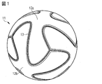
図1は、本発明によるボール11の実施形態を示す。ボール11は、特にサッカーボールである。しかし、本発明は、サッカーボールに限定されず、バスケットボール、バレーボール、ラグビ、フットボール、テニスなどの他のスポーツのボールにも使用され得る。
FIG. 1 shows an embodiment of a
ボール11は、複数のパネルをその外側に備えたシェルを備える。シェルは、パネルで覆われているため、図1には示されない。図1からの複数のパネルのうち2つが、参照番号12aおよび12bそれぞれで参照される。全体として、図1に示すボール11は、6つのパネルを備える。原理上、本発明によるボールは、任意の数、ただし少なくとも2つのパネルを備えうる。図1の実施形態では、ボール11は、参照番号によって指定されないこれ以上のパネルも備える。本発明内で、用語「複数」が使用される限り、これは「2つまたはそれ以上」を意味する。
The
シェルは、空気がボールから逃げることを防止するために通常ボールに使用されるブラダであってもよい。たとえば、ブラダは、バウル(bowel)、ラテックス、またはゴムから製造されてもよい。ブラダは、外部衝撃によるブラダの損傷を防止するように、カーカスで補強されてもよい。この場合、ブラダは、カーカスと共にシェルを形成する。ブラダは、ボール11の膨張を可能にする弁(図に示さず)を有してもよい。
The shell may be a bladder that is normally used on balls to prevent air from escaping from the ball. For example, the bladder may be made from a bowel, latex, or rubber. The bladder may be reinforced with a carcass to prevent damage to the bladder due to external impact. In this case, the bladder forms a shell with the carcass. The bladder may have a valve (not shown) that allows the
たとえば、パネル12a、12bは、皮革、合成皮革、またはプラスチックから製造され得る。パネルは、シェル上に糊付けされ、シェルに溶接され、縫い合わせられ、または別の適切な結合方法によって結合され得る。たとえば、シェルが、接着剤によって完全にコーティングされ、または接着剤に完全に浸されることが可能である。その後、パネル12a、12bは、シェル上に置かれ得る。あるいは、パネル12a、12bが、一方の側において接着剤でコーティングされ、次いで、シェル上にその接着側を接して置かれることも可能である。たとえば、接着剤は、たとえば活性化のために赤外線放射にさらされた溶融接着剤であってもよい。
パネル12a、12bは、これらの間に少なくとも1つの空隙が存在するように配置される。図1の実施形態では、パネル12aとパネル12bの間に空隙が存在する。本発明による空隙は、パネルが空隙の領域内で接触せず、それぞれのパネル間に自由空間が形成されるものと理解される。空隙が、本発明による充填材料によって充填されない場合、パネル12aおよびパネル12bがその上に配置されるシェルを、空隙を通して見ることができる。しかし、本発明によれば、2つのパネルが一方の領域内に空隙を形成し、別の領域では互いに接触することが排除されえない。
For example, the
The
図1の実施形態では、少なくとも1つの空隙が充填材料13によって充填されることも示される。図1の実施形態では、充填材料13は、シェルの外側が空隙の内側で完全に覆われるように空隙を充填しており、これが、図1ではシェルを見ることができない理由である。充填材料13は、硬化前は液体である硬化された充填材料であってもよい。たとえば、充填材料13は、ポリウレタンまたはシリコーンを含んでもよい。
In the embodiment of FIG. 1 it is also shown that at least one void is filled with the filling
本発明の実施形態(図1には示さず)では、充填材料13は発光要素を備えてもよい。たとえば、これは、LED、OLED、マイクロLED、または蛍光性もしくは化学発光性材料、特に暗闇の中で発光する材料であってもよい。原理上、光源をボールの中心に配置し、ボールの中心から外側に光を導く光ファイバを充填材料13内に配置することがさらに可能である。
In an embodiment of the invention (not shown in FIG. 1), the filling
充填材料13は、少なくとも1つの電子要素(図1には示さず)を備えてもよい。たとえば、電子要素は、RFID、またはNFCタグであってもよい。RFIDまたはNFCタグは、適切なレシーバによって読み取られ得る。たとえば、ボールについての情報(たとえば、モデル、または製造番号、真正性の証明書(certificate of authenticity)または原産地証明書など)が、RFIDまたはNFCタグに記憶され得る。
The filling
図1の実施形態では、充填材料13は、少なくとも1つの空隙を完全に充填し、すなわちボール11の下にあるシェルは見ることはできない。しかし、別の実施形態では、充填材料13は、空隙を完全には充填することはできず、すなわち下にあるシェルは、空隙の可能性のある領域で少なくとも見ることができる。
In the embodiment of FIG. 1, the filling
複数のパネルのうち少なくとも1つのパネルは、パネルの外側表面の少なくとも一部上に延びる疑似シーム(図1には示さず)を含んでもよい。疑似シームは、パネル12a、12bの外側表面上の溝形状のくぼみである。手縫いボールのシームとは異なり、疑似シームは、したがって、2つの隣り合うパネルの縫製によって形成されず、手縫いボールのシームを模倣するために溝としてパネル上に形成される。疑似シームは、本発明に関連して充填材料13によって充填され得る。充填材料13は、それによって、疑似シームをほぼ完全に充填することができる。
At least one of the plurality of panels may include a pseudo seam (not shown in FIG. 1) that extends over at least a portion of the outer surface of the panel. The pseudo seam is a groove-shaped depression on the outer surface of the
図2は、本発明に関連して2つのパネル12aと12bの間に形成された空隙21と、疑似シーム22とを断面図で示す。図2では、疑似シーム22は空隙21と共に、充填材料13で充填される。図2の例では、疑似シーム22および空隙21は、最小限のくぼみVMが与えられるように同じ高さHFになるまで充填材料で充填される。最小限のくぼみVMは、ボールの最適な飛行特性を保証するために好ましくは少なくとも1.5mmである。
FIG. 2 shows in cross section a
有利には、外側から見て、空隙21と疑似シーム22の間の相違は現れない。したがって、ボール11は、疑似シームによってほぼ任意の方法で構造化され得る。しかし、空隙21および疑似シーム22内の充填材料13の高さHF、したがってさらに最小限のくぼみVMが異なり、それにより、空隙21および疑似シーム22が、外側から見て光学的に見分けられ得ることも考えられ得る。
Advantageously, the difference between the
図2から見ることができるように、パネル12a、12bは、互いに平行に通るパネルの横方向縁23a、23bと、パネルの外側表面24a、24bとを備える。面取りされたバー25a、25bは、パネルの横方向縁23a、23bの各々を外側表面24a、24bに連結する。図示する実施形態におけるこのタイプの形成により、空隙21の断面のじょうご形状またはY字形状の輪郭が、真似られる。図2に示す空隙が、充填材料13が面取りされた表面25a、25bの間の領域内に延びるように充填材料13によって充填される場合、利点となる。充填材料13の高さHFは、したがって、パネルの横方向縁23a、23bの高さHPSより高く、パネル12a、12bの全高さHPGより低い。充填材料13の高さHFが、パネルの横方向縁23a、23bの高さHPSよりわずかだけ高い場合、特に有利である。さらに、充填材料13の表面26が、図2において点線によって示すような凸状または凹状の形状を含むことも考えられる。凸状または凹状の形状により、製造されたボールの飛行特性は、選択的に影響され得る。このように、触覚性および光学的特性は、さらに影響され得る。
As can be seen from FIG. 2, the
疑似シーム22内の充填材料13の表面26もまた、凸状または凹状の曲率を含んでもよい。
The
以下で説明するような、ボールを製造するための本発明による方法により、充填材料の高さHFまたは最小限のくぼみVMは、所望の飛行特性に応じて個々に調整可能である。 As described below, by the process according to the invention for producing the ball, the height H F or minimal depression V M of the filler material can be adjusted individually depending on the desired flight characteristics.
ボール、特にサッカーボールを製造するための本発明による方法の実施形態が、以下において図3a、3b、3cおよび3dを用いて説明される。 An embodiment of the method according to the invention for producing a ball, in particular a soccer ball, will be described in the following using FIGS. 3a, 3b, 3c and 3d.
方法は、最初のステップとして、シェル31を提供するステップを含む。これは、すでに説明したように、ブラダまたはブラダで補強されたカーカスである。次のステップでは、複数のパネル12a、12b、12c、12dが提供される。たとえば、パネル12a、12b、12c、12dは、それぞれ皮革、合成皮革、またはプラスチックシートから打ち抜きされ得る。また、パネル12a、12b、12c、12dが、射出成形プロセス、深絞りプロセスまたは3Dプリンタを用いて製造されることも考えられる。
The method includes providing a
次のステップでは、複数のパネル12a、12b、12c、12dは、少なくとも2つの隣り合うパネル12a、12b、12c、12d間に少なくとも1つの空隙が存在するように、シェル上に配置される。図3aでは、2つのパネル12aおよび12bが、シェル31上に配置される。図3bでは、別のパネル12cが、シェル31上に配置されており、最終的に図3cでは、第4のパネル12dがシェル31上に配置され、それにより、シェル31は、パネル間の意図的に残る空隙21を除いてほぼ完全に覆われる。空隙は、空隙を形成する隣り合うパネル12a、12b、12c、12dが接触しないようにもたらされる。図1に関連して上記で説明したように、パネルは、たとえばシェル上に糊付けされ得る。
In the next step, the plurality of
方法は、最後に、図3dに示すように、少なくとも1つの空隙21を充填材料13によって充填するステップを含む。充填するステップは、シェル31の外側が空隙21の内側で完全に覆われるように充填材料13が空隙を充填するように実施され得る。
The method finally includes the step of filling at least one
図3a、3b、3cおよび3dに示すように、方法はまた、パネル12a、12b、12cおよび12d上に、パネル12a、12b、12cおよび12dの外側表面の少なくとも一部上に延びる疑似シーム22を形成するステップも含む。すべてのパネルの代わりに、疑似シーム22はまた、パネルのサブセット上、たとえば1つのパネル上に形成されてもよい。疑似シーム22は、それぞれのパネル12a、12b、12c、12d内に切断されまたはミル加工され得る。あるいは、疑似シーム22は、たとえば、射出成形中、それぞれのパネル12a、12b、12c、12d内に形成され得る。
As shown in FIGS. 3a, 3b, 3c and 3d, the method also includes a
図3dに示すように、疑似シーム22は、(たとえばポリウレタンまたはシリコーンベースの)充填材料13によって充填され、それにより、外側から見て、これは、それぞれのパネル12a、12b、12cおよび12d間の空隙21とそれぞれのパネル12a、12b、12cおよび12d上の疑似シーム22との間で光学的に見分けられ得ない。
As shown in FIG. 3d, the pseudo-seam 22 is filled with a filling material 13 (eg polyurethane or silicone based) so that when viewed from the outside, this is between the
充填材料13が液体充填材料13である場合、方法は、液体充填材料13を硬化させるステップをさらに含むことができる。たとえば、充填材料13は、熱またはUV光によって硬化されてもよい。
If the filling
図4は、例示的な方法ステップを示し、ここでは充填材料13は、少なくとも1つの空隙21を充填するために、ロボットアーム41によって外側からシェル31上に施与される。この目的を達成するために、ロボットアーム41は、ノズル42を備え、それによって液体充填材料13が空隙21内に充填される。この方法は、三次元施与技術である。充填材料13は、こうして、この製造方法によってシェル31の外側から空隙21内に入る。
FIG. 4 shows exemplary method steps, in which the filling
ロボットアーム41は、充填材料13の施与中、空隙21の深さおよび幅を測定するセンサ(図4に示さず)を備えてもよい。それによって、充填材料13によって好ましくは均一に充填された空隙を得るために、時間単位あたりの施与される充填材料13の量が、空隙21の幅に合わせて少なくとも調整可能になり得る。あるいは、センサはまた、空隙21の深さを測定してもよく、または断面のジオメトリを完全に測定してもよい。パネル12a、12b、12cおよび12dの互いに対する距離における変動は、こうして補償され得る。ロボットアーム41は、さらに、好ましくは計量装置を備え、それによって充填材料13の噴出が、選択的に制御され得る。
The
本発明による代替の製造方法が、図5および図6の概略的な断面図によって以下において示される。この方法では、パネル12a、12b、12cおよび12dが、型51内に挿入される。型51は、次いで、パネル12a、12b、12cおよび12dが、中央に固定されたシェル31(ブラダまたはカーカスで補強されたブラダ)の方向に移動されるように閉じられる。あるいは、複数のパネル12a、12b、12cおよび12dは、たとえばロボットアームによってシェル31上に配置されてよく、次いで、シェル31が、パネル12a、12b、12cおよび12dと共に型内に配置されてよい。いずれの代替策においても、空隙21が、パネル12a、12b、12cおよび12d間に残る。それと同時に、スリット52が、パネル12a、12b、12cおよび12dと、シェル31の間に残る。スリット52を形成することにより、たとえば、前もって、シェル31および/またはパネル12a、12b、12cおよび12dが接着剤でコーティングされることは必要でない。
An alternative manufacturing method according to the invention is shown below by the schematic cross-sectional views of FIGS. In this method, the
図6は、型51内にパネル12a、12b、12cおよび12dと一緒に配置されたシェル31を示す。それによって、シェル31は、この崩壊を防止するために、入口61上の圧縮された空気によって加圧される。それと同時に、型51は、外側からパネル12a、12b、12cおよび12dに圧力を及ぼす。型51内の別の入口62により、液体充填材料13(たとえば液体ポリウレタン)が、パネル12a、12b、12cおよび12d間の空隙21ならびにパネル12a、12b、12cおよび12dとシェル31の間のスリット内に充填される。この代替的な実施形態では、両方の隣り合うパネル12a、12b、12cおよび12dは一緒に結合され、パネル12a、12b、12cおよび12dの各々は、充填材料13によってシェル31と一緒に結合される。
FIG. 6 shows the
あるいは、空隙21はまた、いかなる形も有さずに発泡ビーズを施与することによって充填され、次いで加熱された型内で硬化されてもよい。発泡ビーズを施与することによる充填は、発泡材料が充填材料13として使用される場合の充填材料13の可能性のある施与の変形形態の一例にすぎない。施与された充填材料13は、それによってさまざまなビーズ発泡体を含んでもよい。
Alternatively, the void 21 may also be filled by applying foam beads without any shape and then cured in a heated mold. Filling by applying foam beads is only one example of a possible application variation of filling
方法の代替的な実施形態では、パネル12a、12b、12cおよび12dは、それぞれの型内に配置され、それらの正確に規定された位置に供給され、次いで、適切なポリウレタンによって埋め戻し発泡され、それと同時にカーカスに結合される透明外側シェルおよび装飾ライナと共にボウルだけを形成することができる。
In an alternative embodiment of the method, the
図6に示すように、型51は、垂直軸63および水平軸64の周りに回転可能に懸架され得る。方法は、次いで、充填材料13が空隙21内で本質的に均一に(すなわち製造における不可避的な変動内で)分散するように型51を回転させるステップを含む。
As shown in FIG. 6, the
さらに、図5および6による方法と図4による方法を組み合わせることも可能である。これにより、パネル12a、12b、12cおよび12d間の空隙21および/またはパネル12a、12b、12c、12dとシェル31との間のスリット52は、図5および図6による本方法にしたがって充填材料13によって型51を用いて充填されることが可能になる。さらに、図4による外側からの射出または施与方法は、充填材料13によって疑似シームを充填するために使用され得る。
Furthermore, it is possible to combine the method according to FIGS. 5 and 6 with the method according to FIG. Thereby, the
11 ボール
12a〜12d パネル
13 充填材料
21 空隙
22 疑似シーム
23a、23b パネルの横方向縁
24a、24b パネルの外側表面
25a、25b 面取りされた表面
26 充填された充填材料の表面
31 シェル
41 ロボットアーム
42 ノズル
51 型
52 スリット
61 空気入口
62 充填材料のための入口
63 垂直軸
64 水平軸
11
Claims (16)
a.シェルを提供するステップと、
b.複数のパネルを型内に提供するステップと、
c.少なくとも2つの隣り合うパネル間に少なくとも1つの空隙が存在するように、かつ前記パネルと前記シェルの間に少なくとも1つの空隙が形成されるように、前記型を用いることによって前記複数のパネルを前記シェル上に配置するステップと、
d.前記少なくとも1つの空隙を充填材料によって少なくとも部分的に充填するステップとを含む、
方法。 A method of manufacturing a ball,
a. Providing a shell, and
b. Providing a plurality of panels in a mold ;
c. The plurality of panels by using the mold such that there is at least one gap between at least two adjacent panels and at least one gap is formed between the panel and the shell; Placing on the shell;
d. At least partially filling the at least one void with a filling material;
Method.
前記シェルを前記複数のパネルと共に型内に配置するステップとをさらに含む、請求項1から10のいずれか一項に記載の方法。 Placing the plurality of panels on the shell by a robot arm;
11. The method of any one of claims 1 to 10 , further comprising placing the shell in a mold with the plurality of panels.
The method of claim 15 , wherein the cross-sectional area of the void is determined in real time by an optical method.
Applications Claiming Priority (2)
| Application Number | Priority Date | Filing Date | Title |
|---|---|---|---|
| DE102015204151.4 | 2015-03-09 | ||
| DE102015204151.4A DE102015204151A1 (en) | 2015-03-09 | 2015-03-09 | Ball, in particular soccer ball, and method of making a ball |
Publications (3)
| Publication Number | Publication Date |
|---|---|
| JP2016165463A JP2016165463A (en) | 2016-09-15 |
| JP2016165463A5 JP2016165463A5 (en) | 2017-09-21 |
| JP6496262B2 true JP6496262B2 (en) | 2019-04-03 |
Family
ID=55524197
Family Applications (1)
| Application Number | Title | Priority Date | Filing Date |
|---|---|---|---|
| JP2016044101A Active JP6496262B2 (en) | 2015-03-09 | 2016-03-08 | Ball, in particular soccer ball, and method of manufacturing the ball |
Country Status (5)
| Country | Link |
|---|---|
| US (3) | US10376750B2 (en) |
| EP (2) | EP3569295A1 (en) |
| JP (1) | JP6496262B2 (en) |
| CN (2) | CN105944339B (en) |
| DE (1) | DE102015204151A1 (en) |
Families Citing this family (41)
| Publication number | Priority date | Publication date | Assignee | Title |
|---|---|---|---|---|
| DE102012206094B4 (en) | 2012-04-13 | 2019-12-05 | Adidas Ag | Soles for sports footwear, shoes and method of making a shoe sole |
| DE102013202291B4 (en) | 2013-02-13 | 2020-06-18 | Adidas Ag | Damping element for sportswear and shoes with such a damping element |
| US9930928B2 (en) | 2013-02-13 | 2018-04-03 | Adidas Ag | Sole for a shoe |
| DE102013002519B4 (en) | 2013-02-13 | 2016-08-18 | Adidas Ag | Production method for damping elements for sportswear |
| DE102013202306B4 (en) | 2013-02-13 | 2014-12-18 | Adidas Ag | Sole for a shoe |
| US9610746B2 (en) | 2013-02-13 | 2017-04-04 | Adidas Ag | Methods for manufacturing cushioning elements for sports apparel |
| USD776410S1 (en) | 2013-04-12 | 2017-01-17 | Adidas Ag | Shoe |
| US20150367183A1 (en) * | 2014-06-23 | 2015-12-24 | Tsung Ming Ou | Method of Producing Sportsball with Sculptural Ball Surface |
| DE102014215897B4 (en) | 2014-08-11 | 2016-12-22 | Adidas Ag | adistar boost |
| DE102014216115B4 (en) | 2014-08-13 | 2022-03-31 | Adidas Ag | 3D elements cast together |
| WO2016097684A1 (en) * | 2014-12-19 | 2016-06-23 | Mitre Sports International Limited | Sports balls |
| DE102015204151A1 (en) * | 2015-03-09 | 2016-09-15 | Adidas Ag | Ball, in particular soccer ball, and method of making a ball |
| JP6679363B2 (en) | 2015-03-23 | 2020-04-15 | アディダス アーゲー | Soles and shoes |
| DE102015206486B4 (en) | 2015-04-10 | 2023-06-01 | Adidas Ag | Shoe, in particular sports shoe, and method for manufacturing the same |
| DE102015206900B4 (en) | 2015-04-16 | 2023-07-27 | Adidas Ag | sports shoe |
| DE102015209795B4 (en) * | 2015-05-28 | 2024-03-21 | Adidas Ag | Ball and process for its production |
| USD783264S1 (en) | 2015-09-15 | 2017-04-11 | Adidas Ag | Shoe |
| USD805143S1 (en) * | 2016-06-13 | 2017-12-12 | Adidas Ag | Ball |
| USD840137S1 (en) | 2016-08-03 | 2019-02-12 | Adidas Ag | Shoe midsole |
| USD840136S1 (en) | 2016-08-03 | 2019-02-12 | Adidas Ag | Shoe midsole |
| USD852475S1 (en) | 2016-08-17 | 2019-07-02 | Adidas Ag | Shoe |
| JP1582717S (en) | 2016-09-02 | 2017-07-31 | ||
| WO2018108781A1 (en) * | 2016-12-14 | 2018-06-21 | Covestro Deutschland Ag | Method for producing a 3d printed, foam-filed object |
| US20180169483A1 (en) * | 2016-12-19 | 2018-06-21 | Tsung Ming Ou | Sportsball with Sculptural Ball Surface |
| US10207158B2 (en) * | 2017-02-28 | 2019-02-19 | Nike, Inc. | Sports ball |
| US10258836B2 (en) | 2017-05-25 | 2019-04-16 | Nike, Inc. | Sports ball with mechanoluminescence |
| USD863474S1 (en) | 2017-08-15 | 2019-10-15 | Nike, Inc. | Ball |
| USD863473S1 (en) | 2017-08-15 | 2019-10-15 | Nike, Inc. | Ball |
| USD863475S1 (en) | 2017-08-15 | 2019-10-15 | Nike, Inc. | Ball |
| USD899061S1 (en) | 2017-10-05 | 2020-10-20 | Adidas Ag | Shoe |
| TWI659767B (en) * | 2018-05-03 | 2019-05-21 | 捷欣企業股份有限公司 | Ball structure and manufacturing method thereof |
| US11148013B2 (en) * | 2018-08-31 | 2021-10-19 | Nike, Inc. | Sports ball |
| US11173351B2 (en) | 2018-08-31 | 2021-11-16 | Nike, Inc. | Sports ball |
| EP4353339A2 (en) * | 2019-01-18 | 2024-04-17 | Nike Innovate C.V. | Sports ball |
| WO2021002983A1 (en) | 2019-07-03 | 2021-01-07 | Nike Innovate C.V. | Sports ball with wickerbill |
| USD921137S1 (en) * | 2019-10-10 | 2021-06-01 | Adidas Ag | Ball |
| US11759681B2 (en) | 2020-02-21 | 2023-09-19 | Nike, Inc. | Sports ball with staggered surface features |
| USD942568S1 (en) * | 2020-03-20 | 2022-02-01 | The Bounty Collegium | Recreational ball |
| US11896882B2 (en) | 2020-11-04 | 2024-02-13 | Xreps, Llc | Extended reality system for training and evaluation |
| DE102021118289A1 (en) | 2021-07-15 | 2023-01-19 | Hans Bohnet | Method of making an object and object |
| DE202021103786U1 (en) | 2021-07-15 | 2021-10-11 | Hans Bohnet | 3-dimensional object and 2-dimensional object |
Family Cites Families (73)
| Publication number | Priority date | Publication date | Assignee | Title |
|---|---|---|---|---|
| US1931429A (en) * | 1932-01-05 | 1933-10-17 | John L Buckner | Football |
| US2182052A (en) * | 1937-11-30 | 1939-12-05 | Milton B Reach | Play or game ball |
| US2182053A (en) * | 1938-01-14 | 1939-12-05 | Milton B Reach | Play or game ball |
| US2278292A (en) * | 1938-10-25 | 1942-03-31 | Voit | Game ball |
| US2579294A (en) * | 1944-08-31 | 1951-12-18 | Spalding A G & Bros Inc | Method of making athletic balls |
| US2843383A (en) * | 1955-01-11 | 1958-07-15 | Spalding A G & Bros Inc | Playball |
| US2879179A (en) * | 1956-04-02 | 1959-03-24 | Tober Baseball Mfg Co Inc | Method of applying plastic composition covers to baseballs |
| US3506265A (en) * | 1967-04-19 | 1970-04-14 | Molten Rubber Ind | Multiple-ply,inflated ball for games |
| US3887416A (en) | 1973-01-22 | 1975-06-03 | Amf Inc | Method of manufacturing a leather covered football |
| BG43028A3 (en) * | 1977-04-13 | 1988-04-15 | Gala Np,Cs | Inflatable sport ball and method for its manufacture |
| US4201313A (en) * | 1978-02-08 | 1980-05-06 | Auto-Place, Inc. | Hopper feeder for singly dispensing short rods or tubes |
| US4318544A (en) * | 1980-10-30 | 1982-03-09 | W. H. Brine Company | Game ball |
| US4856781A (en) * | 1986-01-16 | 1989-08-15 | Molten Corporation | Game ball |
| US4875689A (en) * | 1989-03-09 | 1989-10-24 | Lin Yuh Chorng | Balls for target games |
| JPH0392183A (en) * | 1989-09-05 | 1991-04-17 | Showa Rubber Kk | Method and apparatus for sticking felt of tennis ball |
| US5054778A (en) * | 1991-01-18 | 1991-10-08 | Maleyko John R K | Lighted ball |
| JPH05293415A (en) * | 1992-04-20 | 1993-11-09 | Nissan Motor Co Ltd | Seal material coating apparatus |
| US5310178A (en) * | 1993-01-29 | 1994-05-10 | Lisco, Inc. | Basketball with polyurethane cover |
| US5403000A (en) * | 1993-02-24 | 1995-04-04 | Woosley; John | Illuminated game ball apparatus |
| US5427372A (en) * | 1993-07-01 | 1995-06-27 | Kransco | Applying patches and impressing patterns on ball |
| US5354053A (en) * | 1993-07-01 | 1994-10-11 | Kransco | Play ball |
| JP2717927B2 (en) * | 1993-12-28 | 1998-02-25 | タチカラ株式会社 | Exercise ball and manufacturing method thereof |
| US5541662A (en) | 1994-09-30 | 1996-07-30 | Intel Corporation | Content programmer control of video and data display using associated data |
| EP0705624B1 (en) * | 1994-10-05 | 2000-06-28 | Molten Corporation | A ball for ball game and method for manufacturing the same |
| US6024661A (en) | 1997-10-28 | 2000-02-15 | Wilson Sporting Goods Co. | Sweat-absorbing game ball |
| US5931752A (en) * | 1998-01-15 | 1999-08-03 | Wilson Sporting Goods Co. | Inflatable game ball with laid-in channel or logo |
| US6283881B1 (en) * | 1998-02-06 | 2001-09-04 | Spalding Sports Worldwide, Inc. | Game ball |
| TW407060B (en) | 1998-05-22 | 2000-10-01 | Molten Corp | Ball for ball game |
| US6123633A (en) * | 1998-09-03 | 2000-09-26 | Wilson Sporting Goods Co. | Inflatable game ball with a lobular carcass and a relatively thin cover |
| US6422961B1 (en) * | 1999-01-25 | 2002-07-23 | Spalding Sports Worldwide, Inc. | Rubber basketball with skived channel look |
| US6099423A (en) * | 1999-02-11 | 2000-08-08 | Top Ball Trading Co., Ltd. | Basketball |
| US6406389B1 (en) * | 1999-02-19 | 2002-06-18 | Spalding Sports Worldwide, Inc | Basketball having a carcass with seam areas |
| US6206795B1 (en) * | 1999-07-28 | 2001-03-27 | Tsung Ming Ou | Basketball with cushion layers |
| TW409060B (en) | 1999-12-31 | 2000-10-21 | Yuan Lian Rubber Sporting Good | The manufacture method of rubber basketball |
| US6506135B2 (en) * | 2001-01-22 | 2003-01-14 | Top Ball Trading Co. | Inflatable sportsball with cushion layer |
| TW492339U (en) | 2001-07-03 | 2002-06-21 | Sportex Ind Co Ltd | Improved structure of sewn ball |
| US6663520B2 (en) * | 2001-10-15 | 2003-12-16 | Li Chin Ou Chen | Stitching ball with intermediate construction ball pocket |
| US7029407B2 (en) * | 2002-12-20 | 2006-04-18 | Wilson Sporting Goods Co. | Game ball cover with improved stripes and/or logos |
| US20040259670A1 (en) | 2003-06-18 | 2004-12-23 | Yen-Li Chang | Basketball |
| ES2899606T3 (en) * | 2004-03-30 | 2022-03-14 | Millennium Pharm Inc | Synthesis of ester compounds and boronic acids |
| US20060046879A1 (en) * | 2004-08-30 | 2006-03-02 | Russell Asset Management, Inc. | Sports ball with unitary stripe member |
| US7066853B2 (en) * | 2004-09-30 | 2006-06-27 | Yen-Li Chang | Method for manufacturing an inflatable ball and a ball made with the method |
| US7179181B2 (en) * | 2005-07-19 | 2007-02-20 | Li-Lin Ko | Illuminating ball |
| US9452322B2 (en) * | 2006-08-02 | 2016-09-27 | Wislon Sporting Goods Co. | American football incorporating boundary layer trip mechanisms to reduce aerodynamic drag |
| US8251846B2 (en) * | 2006-08-02 | 2012-08-28 | Wilson Sporting Goods Co. | Game ball having optimally positioned grooves |
| US8182379B2 (en) * | 2008-06-27 | 2012-05-22 | Nike, Inc. | Sport balls and methods of manufacturing the sport balls |
| US20100248873A1 (en) * | 2009-03-30 | 2010-09-30 | John Scott Cooper | Novelty article with flexible and waterproof display carrying membrane |
| DE102009016287B3 (en) | 2009-04-03 | 2010-11-04 | Adidas Ag | ball |
| CN101954172B (en) | 2009-07-14 | 2012-07-04 | 周宏达 | Inflatable sports ball structure and preparation method thereof |
| US8870689B2 (en) | 2009-11-19 | 2014-10-28 | Wilson Sporting Goods, Co. | American-style football including electronics coupled to the bladder |
| US20110207564A1 (en) * | 2010-02-25 | 2011-08-25 | Corey Goodall | Ball having modified surfaces for training |
| US8345546B2 (en) * | 2010-07-13 | 2013-01-01 | Verizon Patent And Licensing Inc. | Dynamic machine-to-machine communications and scheduling |
| US8617011B2 (en) * | 2010-12-03 | 2013-12-31 | Nike, Inc. | Sport ball with indented casing |
| US8602927B2 (en) * | 2010-12-29 | 2013-12-10 | Vertex L.L.C. | Game ball and method of manufacturing same |
| CN202277647U (en) * | 2011-06-07 | 2012-06-20 | 杜昌林 | Noctilucent football with identification coatings |
| US8597144B2 (en) * | 2011-06-28 | 2013-12-03 | Nike, Inc. | Sport ball casing with thermoplastic reinforcing material |
| US9114286B2 (en) * | 2011-09-02 | 2015-08-25 | Wilson Sporting Goods Co. | Basketball having grooved seams |
| US20130206329A1 (en) * | 2011-12-21 | 2013-08-15 | Nike, Inc. | Golf Ball With Thin Biaxial Film Outer Layer |
| CN202410020U (en) | 2011-12-23 | 2012-09-05 | 肇庆川越运动工业有限公司 | Fluorescent stem basketball |
| US9474939B2 (en) * | 2011-12-27 | 2016-10-25 | Nike, Inc. | System and method for making a golf ball with one or more patterned film layers |
| US10449421B2 (en) | 2012-11-09 | 2019-10-22 | Wilson Sporting Goods Co. | Basketball electronics support |
| CN203060714U (en) * | 2012-12-24 | 2013-07-17 | 上海市闸北区中小学科技指导站 | Novel luminous basketball |
| JP5909514B2 (en) * | 2013-03-15 | 2016-04-26 | ウィルソン・スポーティング・グッズ・カンパニーWilson Sporting Goods Company | Basketball shot determination system |
| US20150080155A1 (en) * | 2013-09-13 | 2015-03-19 | Zwyxis HongKong Co., Ltd. | Soccer ball and method of making a soccer ball |
| TWI503148B (en) * | 2013-12-11 | 2015-10-11 | Wei Hung Lin | Sphere structure |
| WO2015099186A1 (en) * | 2013-12-27 | 2015-07-02 | 株式会社モルテン | Ball |
| WO2015111097A1 (en) * | 2014-01-24 | 2015-07-30 | 英臣 宍戸 | Ball for ball sports and manufacturing method for ball for ball sports |
| US9845140B2 (en) * | 2014-06-20 | 2017-12-19 | Austyn D. Crites | High altitude balloon and method and apparatus for its manufacture |
| DE102015204151A1 (en) * | 2015-03-09 | 2016-09-15 | Adidas Ag | Ball, in particular soccer ball, and method of making a ball |
| AU2015408609B2 (en) * | 2015-09-11 | 2018-04-19 | Vikas Gupta | Ball for ball sports and manufacturing method for ball for ball sports |
| JP6448857B2 (en) * | 2016-07-12 | 2019-01-09 | 株式会社モルテン | ball |
| US10207158B2 (en) * | 2017-02-28 | 2019-02-19 | Nike, Inc. | Sports ball |
| TWI659767B (en) * | 2018-05-03 | 2019-05-21 | 捷欣企業股份有限公司 | Ball structure and manufacturing method thereof |
-
2015
- 2015-03-09 DE DE102015204151.4A patent/DE102015204151A1/en active Pending
-
2016
- 2016-03-08 US US15/064,170 patent/US10376750B2/en active Active
- 2016-03-08 JP JP2016044101A patent/JP6496262B2/en active Active
- 2016-03-09 EP EP19180930.0A patent/EP3569295A1/en active Pending
- 2016-03-09 CN CN201610131378.4A patent/CN105944339B/en active Active
- 2016-03-09 EP EP16159328.0A patent/EP3067100B1/en active Active
- 2016-03-09 CN CN202010736343.XA patent/CN112023370B/en active Active
-
2019
- 2019-07-11 US US16/509,027 patent/US11110324B2/en active Active
-
2021
- 2021-09-02 US US17/465,271 patent/US20210394026A1/en active Pending
Also Published As
| Publication number | Publication date |
|---|---|
| DE102015204151A1 (en) | 2016-09-15 |
| US10376750B2 (en) | 2019-08-13 |
| CN112023370B (en) | 2022-03-22 |
| US20190329101A1 (en) | 2019-10-31 |
| EP3067100A1 (en) | 2016-09-14 |
| EP3067100B1 (en) | 2019-06-19 |
| EP3569295A1 (en) | 2019-11-20 |
| JP2016165463A (en) | 2016-09-15 |
| CN112023370A (en) | 2020-12-04 |
| US20210394026A1 (en) | 2021-12-23 |
| US20160263444A1 (en) | 2016-09-15 |
| CN105944339A (en) | 2016-09-21 |
| CN105944339B (en) | 2020-08-28 |
| US11110324B2 (en) | 2021-09-07 |
Similar Documents
| Publication | Publication Date | Title |
|---|---|---|
| JP6496262B2 (en) | Ball, in particular soccer ball, and method of manufacturing the ball | |
| US9283699B2 (en) | Lacrosse head pocket and related method of manufacture | |
| US10814185B2 (en) | Sports ball | |
| JP4157023B2 (en) | Method for producing ball components and method for producing balls | |
| US9387367B2 (en) | Football with segmented cover panels | |
| US20060199685A1 (en) | Machine laminated basketball | |
| CN106715132B (en) | With injection, embedded ink polymer elements and its manufacturing method | |
| US20160089580A1 (en) | Manufacturing method for an outer layer for a panel of a ball | |
| US20130095963A1 (en) | Molded Game Ball and Process of Making the Same | |
| US20170259126A1 (en) | Methods of manufacturing of tri-tech soccer ball | |
| US20150196814A1 (en) | Single panel golf club grip with a decorative layer | |
| CN108076630A (en) | Golf club head with polymer hosel | |
| US6458052B1 (en) | Game ball simulating a sewn cover | |
| CN107890649A (en) | Racket, particularly Pa Deer racket structures |
Legal Events
| Date | Code | Title | Description |
|---|---|---|---|
| A521 | Request for written amendment filed |
Free format text: JAPANESE INTERMEDIATE CODE: A523 Effective date: 20170809 |
|
| A621 | Written request for application examination |
Free format text: JAPANESE INTERMEDIATE CODE: A621 Effective date: 20170809 |
|
| A977 | Report on retrieval |
Free format text: JAPANESE INTERMEDIATE CODE: A971007 Effective date: 20180629 |
|
| A131 | Notification of reasons for refusal |
Free format text: JAPANESE INTERMEDIATE CODE: A131 Effective date: 20180724 |
|
| A601 | Written request for extension of time |
Free format text: JAPANESE INTERMEDIATE CODE: A601 Effective date: 20181024 |
|
| A601 | Written request for extension of time |
Free format text: JAPANESE INTERMEDIATE CODE: A601 Effective date: 20181225 |
|
| A521 | Request for written amendment filed |
Free format text: JAPANESE INTERMEDIATE CODE: A523 Effective date: 20190124 |
|
| TRDD | Decision of grant or rejection written | ||
| A01 | Written decision to grant a patent or to grant a registration (utility model) |
Free format text: JAPANESE INTERMEDIATE CODE: A01 Effective date: 20190305 |
|
| A61 | First payment of annual fees (during grant procedure) |
Free format text: JAPANESE INTERMEDIATE CODE: A61 Effective date: 20190308 |
|
| R150 | Certificate of patent or registration of utility model |
Ref document number: 6496262 Country of ref document: JP Free format text: JAPANESE INTERMEDIATE CODE: R150 |
|
| R250 | Receipt of annual fees |
Free format text: JAPANESE INTERMEDIATE CODE: R250 |
|
| R250 | Receipt of annual fees |
Free format text: JAPANESE INTERMEDIATE CODE: R250 |
|
| R250 | Receipt of annual fees |
Free format text: JAPANESE INTERMEDIATE CODE: R250 |