JP6495457B2 - Gaze tracking system with improved calibration, accuracy compensation, and gaze localization smoothing - Google Patents
Gaze tracking system with improved calibration, accuracy compensation, and gaze localization smoothing Download PDFInfo
- Publication number
- JP6495457B2 JP6495457B2 JP2017532006A JP2017532006A JP6495457B2 JP 6495457 B2 JP6495457 B2 JP 6495457B2 JP 2017532006 A JP2017532006 A JP 2017532006A JP 2017532006 A JP2017532006 A JP 2017532006A JP 6495457 B2 JP6495457 B2 JP 6495457B2
- Authority
- JP
- Japan
- Prior art keywords
- gaze
- calibration
- correction
- noise
- zone
- Prior art date
- Legal status (The legal status is an assumption and is not a legal conclusion. Google has not performed a legal analysis and makes no representation as to the accuracy of the status listed.)
- Active
Links
- 238000009499 grossing Methods 0.000 title claims description 47
- 230000004807 localization Effects 0.000 title 1
- 238000012937 correction Methods 0.000 claims description 101
- 230000006870 function Effects 0.000 claims description 65
- 238000000034 method Methods 0.000 claims description 54
- 238000012549 training Methods 0.000 claims description 3
- 230000008569 process Effects 0.000 description 16
- 238000010801 machine learning Methods 0.000 description 9
- 238000005286 illumination Methods 0.000 description 8
- 238000013528 artificial neural network Methods 0.000 description 6
- 238000010586 diagram Methods 0.000 description 4
- 230000000694 effects Effects 0.000 description 3
- 230000003287 optical effect Effects 0.000 description 3
- 230000004044 response Effects 0.000 description 3
- 230000008901 benefit Effects 0.000 description 2
- 230000008859 change Effects 0.000 description 2
- 238000004891 communication Methods 0.000 description 2
- 238000012886 linear function Methods 0.000 description 2
- 238000012544 monitoring process Methods 0.000 description 2
- 230000004043 responsiveness Effects 0.000 description 2
- 206010044565 Tremor Diseases 0.000 description 1
- 230000002159 abnormal effect Effects 0.000 description 1
- 230000006399 behavior Effects 0.000 description 1
- 230000005540 biological transmission Effects 0.000 description 1
- 238000004590 computer program Methods 0.000 description 1
- 230000001419 dependent effect Effects 0.000 description 1
- 238000013461 design Methods 0.000 description 1
- 238000001514 detection method Methods 0.000 description 1
- 238000005516 engineering process Methods 0.000 description 1
- 238000001914 filtration Methods 0.000 description 1
- 238000005259 measurement Methods 0.000 description 1
- 238000010606 normalization Methods 0.000 description 1
- 238000012545 processing Methods 0.000 description 1
- 238000012887 quadratic function Methods 0.000 description 1
- 230000009467 reduction Effects 0.000 description 1
- 239000007787 solid Substances 0.000 description 1
- 230000000007 visual effect Effects 0.000 description 1
Images


Classifications
-
- A—HUMAN NECESSITIES
- A61—MEDICAL OR VETERINARY SCIENCE; HYGIENE
- A61B—DIAGNOSIS; SURGERY; IDENTIFICATION
- A61B3/00—Apparatus for testing the eyes; Instruments for examining the eyes
- A61B3/10—Objective types, i.e. instruments for examining the eyes independent of the patients' perceptions or reactions
- A61B3/113—Objective types, i.e. instruments for examining the eyes independent of the patients' perceptions or reactions for determining or recording eye movement
-
- G—PHYSICS
- G06—COMPUTING; CALCULATING OR COUNTING
- G06F—ELECTRIC DIGITAL DATA PROCESSING
- G06F3/00—Input arrangements for transferring data to be processed into a form capable of being handled by the computer; Output arrangements for transferring data from processing unit to output unit, e.g. interface arrangements
- G06F3/01—Input arrangements or combined input and output arrangements for interaction between user and computer
- G06F3/011—Arrangements for interaction with the human body, e.g. for user immersion in virtual reality
- G06F3/013—Eye tracking input arrangements
Description
この発明は注視追跡の分野に関し、詳細には、改善された較正処理、局所的な正確性の補償、及び局所的な注視の平滑化を提供するシステム及び方法に関する。 The present invention relates to the field of gaze tracking, and in particular to systems and methods that provide improved calibration processing, local accuracy compensation, and local gaze smoothing.
注視追跡を用いて表示デバイス上の選択肢の選択や表示画像内の関心物体の識別を制御することは、特に低コストの注視追跡デバイス及びソフトウェア、たとえば、Tobii Technology社及びThe Eye Tribeにより提供されるものなどの可用性の観点から増加し続けている。 Using gaze tracking to control selection of choices on the display device and identification of objects of interest in the displayed image is provided by particularly low-cost gaze tracking devices and software, such as Tobii Technology and The Eye Tribe It continues to increase from the viewpoint of availability of things.
また、注視追跡は「受動(passive)」モードで使用することもでき、このモードでは、ユーザの注視パターンを監視して、画像の構成、たとえば、ウェブページ、ゲームプログラム上などの要素の配置に対するユーザの反応を決定する。また、受動的監視は生理学的研究に、たとえば異なる人々が模擬された異なる車両状況にどのように反応するかを決定するために使用され得る。同様に、受動的監視は、運転者の注視が異常である場合に警告を発するために車両内で実施することができる。 Gaze tracking can also be used in a “passive” mode, in which the user's gaze pattern is monitored to monitor the composition of the image, eg, the placement of elements such as on a web page, game program, etc. Determine user response. Passive monitoring can also be used in physiological studies, for example, to determine how different people react to different simulated vehicle situations. Similarly, passive monitoring can be implemented in the vehicle to issue a warning if the driver's gaze is abnormal.
従来の注視追跡デバイスでは、光学デバイス、たとえばカメラ並びに赤外線放出器及び受信器、又は他のデバイス、たとえば生体パラメータを測定するデバイスを用いて、「真っ直ぐ前方」からの角度のずれが測定される。例示的な注視追跡デバイス及びそれらの応用は、Blixtらによる「VISUAL DISPLAY WITH ILLUMINATORS FOR GAZE TRACKING」というタイトルの2011年3月24日出願の米国特許出願公開第2011/0069277号、Skogoらによる「EYE/GAZE TRACKER AND METHOD OF TRACKING THE POSITION OF AN EYE AND/OR A GAZE POINT OF A SUBJECT」というタイトルの2014年3月7日出願の米国特許出願公開第2014/0268055号、Hennesseyらによる「SYSTEM AND METHOD FOR INTERACTING WITH AND ANALYZING MEDIA ON A DISPLAY USING EYE GAZE TRACKING」というタイトルの2013年4月25日出願の米国特許出願公開第2013/0235347号、Surらによる「APPARATUS AND METHODS FOR CONFIGURATION AND OPTIMIZATION OF IMAGE SENSORS FOR GAZE TRACKING APPLICATIONS」というタイトルの2008年8月4日出願の米国特許出願公開第2009/0268045号、Frederick Jan De Bruijn、Karl Catherine Van Bree及びTommaso Grittiによる「SYSTEM AND METHOD FOR TRACKING THE POINT OF GAZE OF AN OBSERVER」というタイトルの2011年3月15日出願の米国特許出願公開第2013/0002846号、並びに、Leeらによる「APPARATUS AND METHOD FOR CONTROLLING GAZE TRACKING」というタイトルの2013年5月7日出願の米国特許出願公開第2014/0160005号に見出すことができる。これらの引用文献のそれぞれは、本明細書に引用により組み込まれている。 In conventional gaze tracking devices, angular deviations from “straight forward” are measured using optical devices such as cameras and infrared emitters and receivers, or other devices such as devices that measure biological parameters. Exemplary gaze tracking devices and their applications are described in US Patent Application Publication No. 2011/0069277, filed March 24, 2011, entitled “VISUAL DISPLAY WITH ILLUMINATORS FOR GAGE TRACKING” by Blixt et al., “EYE” by Skogo et al. US Patent Application Publication No. 2014/0268055 filed on March 7, 2014, HANDESYSTEM et al., HENSESYSTEM et al., HENSESEST et al. FOR INTERACTING WITH AND ANALYZING US Patent Application Publication No. 2013/0235347 filed April 25, 2013 entitled "EDIA ON A DISPLAY USING EYE GAZING TRACKING", Sur et al. US Patent Application Publication No. 2009/0268045, filed Aug. 4, 2008, Frederick Jan De Bruijn, Karl Catherine Van Bree and Tommaso Gritti, "SYSTEM AND METHOD FOR TRACKING THE". US Patent Application Publication No. 2013/0002846 filed March 15, 2011 entitled “POINT OF GAGE OF AN OBSERVER”, and May 7, 2013 entitled “APPARATUS AND METHOD FOR CONTROL LAGING TRACKING” by Lee et al. It can be found in US Patent Application Publication No. 2014/0160005 of Japanese application. Each of these references is incorporated herein by reference.
ユーザの注視を表示画面上の位置に正確にマッピングするために、注視追跡デバイスは、各ユーザの光学特性を補償するための較正手順を決定し、適用する。この較正は能動的であってもよく、たとえばユーザは表示画面上の特定の点を注視するように指示され、又は受動的であってもよく、たとえばデバイスは、ユーザが表示デバイスを見ている間に既知の位置から刺激を与え、刺激がユーザの目に当たる角度を検出する。 In order to accurately map the user's gaze to a location on the display screen, the gaze tracking device determines and applies a calibration procedure to compensate for each user's optical properties. This calibration may be active, for example, the user may be instructed to watch a particular point on the display screen, or may be passive, for example, the device is viewing the display device by the user In the meantime, a stimulus is applied from a known position, and an angle at which the stimulus hits the user's eyes is detected.
図1は、The Eye Tribeにより提供されるデバイスで使用されるものなどの能動的な較正の間に使用され得る例示的な照明パターン100を示す。パターンは、9つの選択可能な照明点120、すなわち「ターゲット」を有する暗い背景110を備える。デバイスの較正要素は、照明点の1つを選択的に照明し、ユーザが照明された点を注視しているときのユーザの目の角度を検出する。例示的な較正要素は、表示デバイスに対するユーザの目の位置及び3Dジオメトリに基づいて、ユーザの目からの各照明点の「真の」角度を決定する。照明点を観察しているときのユーザの目の各測定された(「実際の」)角度と、ユーザの目からの照明点の「真の」角度との差は、この特定のユーザについての「誤差」要因を規定する。
FIG. 1 shows an
様々な技法のいずれかを用いて、「補正された」角度と「真の」角度との間の誤差を最小化する「実際の」角度に適用される補正関数を決定することができる。一例示的実施形態では、「実際の」角度に適用されるオフセット及びスケーリング係数を含む誤差の二乗の総和を最小化する線形補正関数が決定される。非線形補正関数、たとえば誤差を最小化する二次関数も使用することができる。 Any of a variety of techniques can be used to determine the correction function applied to the “real” angle that minimizes the error between the “corrected” angle and the “true” angle. In one exemplary embodiment, a linear correction function is determined that minimizes the sum of the squares of the errors, including the offset and scaling factor applied to the “real” angle. Nonlinear correction functions, such as quadratic functions that minimize errors, can also be used.
補正関数の使用の制限は、単一の補正関数でモデル化可能な、誤差における一定の「一様性」を仮定していることである。すなわち、たとえば、線形補正関数を使用することは、誤差がディスプレイにわたって線形変化を示すことを仮定しており、二次補正関数は、誤差が二次(平方)効果に対応するパターンを示すことを仮定している。 The limitation of using a correction function is that it assumes a certain “uniformity” in error that can be modeled with a single correction function. That is, for example, using a linear correction function assumes that the error exhibits a linear change across the display, and that the quadratic correction function indicates that the error exhibits a pattern corresponding to a quadratic (square) effect. Assumes.
従来の補正関数は一般的には、提供元/開発元により提供される注視追跡ソフトウェアに含まれており、その理由は開発元が、真の角度を決定するのに使用されるアルゴリズム及び測定された角度を知っており、利用される特定の注視追跡技法により導入される誤差を決定し補償することが最も可能であるためである。追加的に、表示画像上でユーザが注視している場所を決定するのに使用される注視追跡デバイスの例では、ディスプレイ上の注視点の座標が決定される前に、角度補正関数が適用されなければならない。 Traditional correction functions are typically included in gaze tracking software provided by the supplier / developer, because the developer uses the algorithm and measurement used to determine the true angle. This is because it is most possible to determine and compensate for errors introduced by the particular gaze tracking technique utilized. Additionally, in the example of a gaze tracking device that is used to determine where the user is gazing on the displayed image, an angle correction function is applied before the coordinates of the gaze point on the display are determined. There must be.
注視追跡デバイスにより与えられる結果を用いるアプリケーションの開発元は、自社のアプリケーションに様々な注視追跡デバイスとの互換性を持たせて、自身のアプリケーションにより広範な市場での魅力を与えることを望むことが多い。好ましくは、これらのアプリケーションは、異なる注視追跡デバイスの特性に無関係に、同一の機能的効用を提供するべきである。同様に、アプリケーションは、使用されるディスプレイの大きさに無関係に(実用的な限度内で)、同一の機能的効用を提供するべきである。 Developers of applications that use the results provided by gaze tracking devices may wish to make their applications compatible with various gaze tracking devices and make their applications more attractive in the broader market. Many. Preferably, these applications should provide the same functional utility regardless of the characteristics of different gaze tracking devices. Similarly, the application should provide the same functional utility regardless of the display size used (within practical limits).
異なる注視追跡デバイスが異なるレベルの正確性又は精度を示す場合、アプリケーションの開発元は、正確性が最も劣るデバイスと互換性を持つようにアプリケーションを設計しなければならない(これはアプリケーションの機能性を制限し得る)か、又は最も劣る注視追跡デバイスの提供元と協力して、その注視追跡デバイスの固有の正確性を強化しなければならない。 If different gaze tracking devices exhibit different levels of accuracy or precision, the application developer must design the application to be compatible with the least accurate device (this reduces the functionality of the application). Must be limited) or in cooperation with the provider of the worst gaze tracking device to enhance the inherent accuracy of that gaze tracking device.
異なる正確性の特性に加えて、異なる注視追跡デバイスは、たとえば、ターゲットを注視している間の目の実際の微動、注視角の計算に使用されるアルゴリズムに内在する変動、注視角の検出に使用されるセンサにより提供される信号の変動などの要因により生じる「ノイズ」又は「ジッタ」などの他の性能要因の差も示す。特定の注視追跡デバイスに応じて、デバイスは、ディスプレイ上の各座標の各決定に対応する「生」データ、又は決定された座標の移動平均などに対応する「平滑化された」データを提供することができる。生データのストリームはアプリケーション内で平滑化アルゴリズムを必要とするが、平滑化されたデータは注視追跡デバイスの応答性にラグを導入する。 In addition to different accuracy characteristics, different gaze tracking devices can be used to detect, for example, the actual tremor of the eye while gazing at the target, variations inherent in the algorithm used to calculate the gaze angle, and gaze angle detection. It also shows differences in other performance factors such as “noise” or “jitter” caused by factors such as variations in the signal provided by the sensor used. Depending on the particular gaze tracking device, the device provides “raw” data corresponding to each determination of each coordinate on the display, or “smoothed” data corresponding to a moving average of the determined coordinates, etc. be able to. While the stream of raw data requires a smoothing algorithm within the application, the smoothed data introduces a lag in the responsiveness of the gaze tracking device.
ユーザの測定された注視に関連する誤差がユーザの視野にわたって均一の挙動を示すという仮定に基づかない注視追跡のための較正方法及びシステムを提供することが有利であろう。また、ディスプレイ上の注視点座標を提供するのに使用される技術に実質的に無関係な注視追跡システムを提供することが有利であろう。また、この較正方法に基づいて正確性が改善された注視追跡システムを提供することが有利であろう。また、この較正に基づいて改善されたノイズ低減(平滑化)を提供することが有利であろう。 It would be advantageous to provide a calibration method and system for gaze tracking that is not based on the assumption that errors associated with the user's measured gaze exhibit uniform behavior across the user's field of view. It would also be advantageous to provide a gaze tracking system that is substantially independent of the technique used to provide the gaze coordinates on the display. It would also be advantageous to provide a gaze tracking system with improved accuracy based on this calibration method. It would also be advantageous to provide improved noise reduction (smoothing) based on this calibration.
これらの懸案事項の1つ又は複数により良く対処するために、この発明の一実施形態では、「局所化された」誤差補正を適用することができる。表示エリアを誤差補正ゾーンに分割することができ、各ゾーンはそれ自体の誤差補正パラメータ又は関数を有することができる。較正点をこれらのゾーンのそれぞれについて規定することができ、各ゾーン内の補正パラメータ又は関数は、ユーザがゾーンに関連付けられた各較正点を見た場合の観測された誤差に依存し得る。同様に、決定された注視点を平滑化してノイズを低減させるために適用される関数も、その特性を規定されたノイズ較正ゾーンに関連付けられた各較正点において生じるノイズに基づかせることによって、局所化することができる。誤差補正関数及び/又はノイズ平滑化関数は、補正及び平滑化された注視位置を受信する特定のアプリケーションの要件に基づいて選択することができる。 In order to better address one or more of these concerns, in one embodiment of the present invention, “localized” error correction can be applied. The display area can be divided into error correction zones, and each zone can have its own error correction parameters or functions. Calibration points can be defined for each of these zones, and the correction parameters or functions within each zone can depend on the observed error when the user views each calibration point associated with the zone. Similarly, the function applied to smooth the determined gazing point to reduce noise is also localized by basing its characteristics on the noise occurring at each calibration point associated with the defined noise calibration zone. Can be The error correction function and / or the noise smoothing function can be selected based on the requirements of the particular application receiving the corrected and smoothed gaze position.
この発明の注視追跡システムの一例示的実施形態は、ユーザの注視に基づいて表示エリア上の位置を特定する注視追跡デバイスと、表示エリアのゾーンに関連付けられた複数の較正点のそれぞれについて補正係数を決定する注視較正要素と、決定された補正係数に基づいて、補正された位置をアプリケーションに提供する注視補正要素とを含むことができる。 An exemplary embodiment of the gaze tracking system of the present invention includes a gaze tracking device that identifies a position on a display area based on a user's gaze and a correction factor for each of a plurality of calibration points associated with a zone of the display area. And a gaze correction element that provides a corrected position to the application based on the determined correction factor.
例示的な注視較正要素は、表示エリア上に複数の較正点を規定し、較正点ごとに、較正位置を照明し、ユーザが照明された較正点を注視したときの表示エリア上の報告された位置を受信し、報告された位置と較正点との差に基づいて較正点に関連するオフセット誤差を決定する。その後、較正要素は、少なくとも1つの較正位置におけるこれらのオフセット位置誤差に基づいて、較正点ごとに補正オフセットを決定する。 An exemplary gaze calibration element defines a plurality of calibration points on the display area, and for each calibration point, illuminates the calibration location and is reported on the display area when the user gazes at the illuminated calibration point. A position is received and an offset error associated with the calibration point is determined based on the difference between the reported position and the calibration point. The calibration element then determines a correction offset for each calibration point based on these offset position errors at the at least one calibration position.
例示的な注視補正要素は、続いて、ディスプレイ上の報告された注視位置を注視追跡デバイスから受信し、報告された注視位置に対応するゾーンを決定し、このゾーンについての補正関数を、そのゾーンに関連付けられた各較正点の補正オフセットに基づいて適用して、補正された位置を決定するために報告された注視位置に適用され得る補正オフセットを決定する。この補正された位置はアプリケーションに伝達され、アプリケーションは補正された位置を用いて、補正された注視位置に応じた関数を実行する。 The exemplary gaze correction element subsequently receives a reported gaze position on the display from the gaze tracking device, determines a zone corresponding to the reported gaze position, and calculates a correction function for the zone Applied based on the correction offset of each calibration point associated with, to determine a correction offset that can be applied to the reported gaze position to determine the corrected position. The corrected position is transmitted to the application, and the application executes a function corresponding to the corrected gaze position using the corrected position.
同様に、表示エリアをノイズ補正ゾーンに分割することができ、決定された注視位置に関連するノイズを低減させるために適用される平滑化関数も、報告された注視位置が存在するノイズ補正ゾーンに依存し得る。 Similarly, the display area can be divided into noise correction zones, and the smoothing function applied to reduce the noise associated with the determined gaze position is also in the noise correction zone where the reported gaze position exists. Can depend.
本発明はさらに詳細に、例として、添付図面を参照して説明される。 The invention will be described in further detail, by way of example, with reference to the accompanying drawings.
図面全体を通して、同一の参照符号は類似した又は対応する特徴又は機能を示す。図面は説明の目的で含まれており、本発明の範囲を限定することは意図されていない。 Throughout the drawings, identical reference numbers indicate similar or corresponding features or functions. The drawings are included for illustrative purposes and are not intended to limit the scope of the invention.
以下の説明では、限定ではなく説明の目的で、具体的な詳細、たとえば特定のアーキテクチャ、インターフェース、技法などが記載されており、これは本発明の概念の完全な理解を与えるためである。しかしながら、本発明が、これらの具体的な詳細から逸脱する他の実施形態において実施可能であることは、当業者には明らかであろう。同様に、この明細書の文章は、図面に示された例示的実施形態のためのものであり、特許請求の範囲に明示的に含まれる限定を超えて、特許請求された発明を限定するよう意図されていない。簡潔さ及び明瞭さのために、よく知られたデバイス、回路、及び方法の詳細な説明は、本発明の説明を不要な詳細で不明瞭にしないように省略されている。 In the following description, for purposes of explanation and not limitation, specific details are set forth, such as specific architectures, interfaces, techniques, etc., in order to provide a thorough understanding of the concepts of the present invention. However, it will be apparent to those skilled in the art that the present invention may be practiced in other embodiments that depart from these specific details. Similarly, the text of this specification is for the exemplary embodiments shown in the drawings and is intended to limit the claimed invention beyond the limitations explicitly included in the claims. Not intended. For the sake of brevity and clarity, detailed descriptions of well-known devices, circuits, and methods have been omitted so as not to obscure the description of the present invention with unnecessary detail.
この発明の一例示的実施形態では、従来の注視追跡デバイス210を用いて、ユーザ230が注視していると注視追跡デバイス210が決定した表示エリア220上の位置に対応する座標を提供する。注視追跡デバイス210は、ユーザの現在の注視方向に対応する表示エリア220上の座標を報告するように完全に構成される。すなわち、ユーザ230が表示エリア220を注視しているときの注視座標を報告するために特定のデバイス210により要求される任意の較正が実施されている。デバイス210を用いて注視座標を報告するためにそのような較正が任意選択である場合、この発明で使用することも任意選択である。
In an exemplary embodiment of the invention, a conventional
較正要素250は、後述の較正処理に基づいて、報告された位置を補正することを目的とする1つ又は複数の誤差補正関数260を提供するように構成される。以下で使用される場合、「補正関数」という用語は、異なる形式を有する関数、又は同一の形式を有するが異なるパラメータを有する関数を含む。たとえば、補正関数は線形及び非線形関数を含むことができ、又はそれぞれ、共通のタイプの関数、たとえば線形関数(x’=a+b*x)であるが潜在的に異なるパラメータ値(オフセットa及び傾きb)を有するものとすることができる。
The
補正要素270は、これらの誤差補正関数260の少なくとも1つを報告された位置に適用して補正された位置を生成するように構成され、補正された位置は、表示エリア220上の注視に基づく位置を用いて所与の機能を実施するアプリケーション280により使用することができる。
The
図3に示されるように、ユーザが注視する表示エリア100はゾーン320に分割することができ、各ゾーン320は少なくとも1つの較正位置310を含む。較正位置310を用いて各ゾーン320を規定することができ、又はゾーン320を用いて較正位置310を規定することができる。一般的には、ゾーン320の数及び大きさは、正確性及び解像度の所望の程度、表示エリアの大きさ、並びに注視追跡デバイスの予想される正確性に依存する。
As shown in FIG. 3, the
図3では、較正点310は各矩形ゾーン320の頂点である。以下でさらに詳述されるように、較正点及びゾーンの他の配置を使用することができる。たとえば、図3の較正点310を用いて、表示エリア100の代替的な分割を、較正点310のそれぞれを中心とする矩形ゾーンとすることができる。
In FIG. 3, the
較正点310のパターンと、特に較正点及びゾーンの数とは、事前規定することができ、又はユーザ規定可能とすることができる。いくつかの実施形態では、特定のアプリケーション280の提供元が、所与の正確性及び解像度を指定することができ、較正要素350は、注視追跡デバイス210の特定の特性、ディスプレイ220の大きさ、及び/又は他の要因を前提としてこれらの要件を満足する較正点310の適切なパターンを選択するように構成することができる。
The pattern of calibration points 310, and in particular the number of calibration points and zones, can be predefined or user definable. In some embodiments, the provider of a
この発明の一実施形態では、図2の較正要素250は、たとえば、較正点310のそれぞれを順次照明するか、又はそれと同等に、較正点310を中心とするディスプレイのエリア、たとえば各較正点310を囲む図示された白い円を照明することによって、各較正点310を順次目立たせるように構成することができる。
In one embodiment of the present invention, the
照明は固定の持続時間とすることができ、その間に較正要素250は、表示エリア100上のユーザの注視の決定された座標(以下、注視点又は注視座標)を注視追跡デバイス210から受信する。較正要素250は、前に照明された較正点310からユーザが変化すると、次の較正点については最初に報告された座標を無視することができる。
The illumination can be of fixed duration, during which time the
また、較正要素250は、照明された較正点についての注視点の記録が完了し、較正点が変化しつつあり、そして再び、新たに照明された較正点310に対応する報告された注視座標を記録し始めるときに、可聴信号を提供してもよい。
The
代替的に、ユーザはマウスクリックなどのトリガを用いて、ユーザが照明された較正点を現在注視していることを較正要素250に通知することができ、較正要素250は報告された注視点の記録を開始することができる。
Alternatively, the user can use a trigger, such as a mouse click, to notify the
いくつかの実施形態では、較正点の全てを照明することができ、ユーザは較正点のそれぞれを順次注視し、次いで較正点の全てが注視されたことを較正要素250に通知する。次いで、較正要素250は、クラスタリングなどの技法を用いて、記録された注視点を各較正点に関連付け、ユーザの注視がある較正点から次の較正点にシフトした間に記録された注視点である可能性の高い外れ値を無視することができる。
In some embodiments, all of the calibration points can be illuminated, and the user gazes at each of the calibration points sequentially, and then notifies the
以下でさらに詳述されるように、各較正点310における報告された注視座標を記録した後、較正要素250は、較正点ごとのこれらの報告された注視座標に対応する単一の測定された注視座標を決定することができ、この単一の測定された注視座標を対応する較正点の既知の座標と比較して、各較正点に関連する誤差要因を決定することができる。
As will be described in more detail below, after recording the reported gaze coordinates at each
較正点ごとの注視座標の記録が開始されると、較正要素250は、注視追跡デバイス210からの所定数の報告された注視座標を記録することができる。或いは、較正要素250は、これらの報告された座標間の分散が、測定された注視座標の信頼できる決定が可能であることを示すまで、注視座標を記録し続けるように構成することができる。すなわち、たとえば、ユーザの注視が安定しており、報告された注視座標間の差がほとんどない場合には、少数の報告された注視座標が受信された後に記録を終了させることができる。他方、ユーザの注視が定まらないか或いは不安定であって、報告された注視座標間の差が比較的大きい場合、較正要素250は、より多数の報告された注視座標を記録し続けて、較正点についての単一の測定された注視座標を決定するためにより大きいサンプルサイズを提供することができる。
Once recording of gaze coordinates for each calibration point is initiated,
いくつかの実施形態では、所定数のサンプル及び可変数のサンプルの組合せを使用することができる。たとえば、典型的なユーザは、表示エリア100の中心付近の較正点への安定した焦点を維持することができ、表示エリア100の周囲付近の較正点に焦点を合わせる能力が低い傾向があると決定することができ、較正要素250は、ディスプレイ100の中心付近の較正点において所定数のサンプルを収集し、ディスプレイ100の中心からの各較正点の距離が増加するにつれてより多い所定数のサンプルを収集するように構成することができる。
In some embodiments, a combination of a predetermined number of samples and a variable number of samples can be used. For example, a typical user can maintain a stable focus on calibration points near the center of the
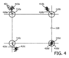
図4は、ユーザが各較正位置310a〜310dを注視したときの例示的な測定された注視位置のセット410a〜410dを示す。各較正位置410a〜410dについての個々の報告された注視点401が示されている。これらの注視点401はそれらの対応する較正位置410a〜410dから決定可能な距離に位置しており、この距離は注視追跡デバイス210からの各報告された注視点401の誤差に対応する。較正要素250はこれらの注視点401を処理して、各対応する較正点310a〜310dにおける単一の測定された注視位置410a〜410dを決定する。一例示的実施形態では、各較正点310a〜310dについての測定された注視位置410a〜410dは、当技術分野では一般的な技法を用いて、較正点310a〜310dに関連する各報告された注視位置401の誤差の二乗の総和を最小化する位置とすることができる。他の技法を用いて、各較正点に関連する注視位置の各セットに対応する単一の測定された注視位置を決定することができる。
FIG. 4 shows an exemplary measured gaze position set 410a-410d as the user gazes at each
この例示的な報告された注視位置のセット410a〜410dは、非一様かつ非線形の位置誤差のセット、又は測定された注視位置410a〜410dと較正点310a〜310dの真の位置との間のオフセット420a〜420dを示す。特定のディスプレイ220上の注視位置を報告するために特定のユーザ230により使用される特定の注視追跡デバイス210は、較正点310aのわずかに左であって実質的に上方であるオフセット420aと、較正点310bの実質的に左であって上方であるオフセット420bと、較正点310cの実質的に右であって下方であるオフセット420cと、較正点310dに関する無視できるオフセット420d(それ自体は図示せず)とを示す。
This exemplary reported gaze position set 410a-410d is a non-uniform and non-linear position error set, or between the measured
これらのオフセットOa(x,y)420a、Ob(x,y)420b、Oc(x,y)420c、及びOd(x,y)420dのそれぞれは、各較正点310a〜310dについてそれぞれ記録される。上記の処理は、N個の較正点のそれぞれに適用されて、N個の較正点のそれぞれに関連するオフセットO1(x,y)、O2(x,y)、...ON(x,y)をもたらす。図3の例では、N=54(9×6)個の較正点がある。
Each of these offsets Oa (x, y) 420a, Ob (x, y) 420b, Oc (x, y) 420c, and Od (x, y) 420d is recorded for each
留意すべき重要なことは、図3の各ゾーン320が較正点310の異なるセットに関連付けられており、したがって異なる較正オフセット値のセットに関連付けられていることである。以下でさらに詳述されるように、所与のゾーンに関連付けられた特定の較正オフセット値のセットは、注視追跡デバイス210からのその後報告される注視座標に適用される特定の補正関数のパラメータを規定する。
It is important to note that each
各較正点310の位置及びその対応するオフセット値は、注視補正要素270に提供することができる。代替的に、特に注視較正要素250及び補正要素270が共通のモジュール内にある場合、注視補正要素270は、注視較正要素250への呼び出しを介して、又はこのデータ260を記憶するために較正要素250により使用される同一のメモリへのアクセスを介して、このデータ260にアクセスするように構成することができる。
The position of each
図5は、ゾーン320に関連付けられた各較正点310a〜dに関連する誤差(オフセット)420a〜dに基づいた報告された注視位置510の例示的な補正を示す。この例では、較正点310a〜dは、矩形ゾーン320の4つの頂点を規定する。報告された注視位置510が注視補正要素270により受信されると、注視補正要素270は、注視位置510が存在するゾーンを決定し、次いでそのゾーンに関連付けられた較正点の位置及びそれらの対応するオフセットを用いて、注視位置510に適用すべき適切な補正オフセットを決定することによって、補正された注視位置520を提供する。
FIG. 5 illustrates an exemplary correction of the reported
注視位置510は較正点310aに最も近く、較正点310dから最も遠いので、注視位置510に適用して補正された位置530を生成することが可能な補正520は、較正点310aに関連するオフセット420aによってより強く影響され得る。同様に、注視位置510は、下側の較正点のペア310c、310dよりも上側の較正点のペア310a〜310bに近く、注視位置510の垂直補正は、上側の較正点のペア310a、310bに関連するオフセット420a、420bによってより強く影響され得る。
Since the
任意数の技法、たとえば多変量補間などを用いて、較正オフセット420a〜420d(この例でのオフセット420dは無視でき、それ自体は図示されていない)のそれぞれの影響を反映する補正オフセット520を、較正点310a〜310dに対する注視位置510の位置に基づいて決定することができる。
Using any number of techniques, such as multivariate interpolation, etc., a correction offset 520 that reflects the respective effects of
一例示的実施形態では、多変量補間は「距離加重」に基づいており、補正オフセットは注視点510と較正点310a〜310bのそれぞれとの間の距離540a〜540dに基づいており、距離は、各較正点310a〜310dのオフセット420a〜420dが決定された補正オフセット520に及ぼし得る影響を示す重みを規定し、より小さい重みがより離れた較正点に与えられる。
In one exemplary embodiment, multivariate interpolation is based on “distance weighting”, the correction offset is based on distances 540a-540d between the
Pgを注視点510とし、Ca、Cb、Cc、及びCdは較正点310a〜310dを表し、Da、Db、Dc、及びDdは、対角線上に位置する較正点の間の対角線距離(すなわち、CaとCdの間、又はCbとCcの間の距離)により正規化された距離540a〜dを表す。Oa、Ob、Oc、及びOdは、オフセット420a〜420dを表すものとする。各オフセットOa、Ob、Oc、及びOdの重みは、それぞれ(1−Da)、(1−Db)、(1−Dc)、及び(1−Dd)と規定することができる。
Let Pg be the
注視点Pg510に適用可能なオフセットOp520は、
Op=(1−Da)*Oa+(1−Db)*Ob+(1−Dc)*Oc+(1−Dd)*Od
と規定することができる。
The offset Op520 applicable to the gazing point Pg510 is
Op = (1-Da) * Oa + (1-Db) * Ob + (1-Dc) * Oc + (1-Dd) * Od
Can be defined.
この技法の利点は、適切な正規化が適用されている(重みの総和が1.0に等しい)場合に、任意に位置付けられた較正点のセットに適用できることである。同様に、この技法は、図3で使用された4つよりも多い又は少ない較正点によって規定されるゾーンに適用することができる。いくつかの実施形態では、ゾーンは、ゾーン内並びにゾーンの外周上の較正点を含み、たとえば、ゾーンは3×3の較正点の配置であって、中央の較正点及びその外周に沿った8つの較正点を有するものを含むことができる。 The advantage of this technique is that it can be applied to an arbitrarily positioned set of calibration points when appropriate normalization is applied (the sum of the weights is equal to 1.0). Similarly, this technique can be applied to zones defined by more or fewer than four calibration points used in FIG. In some embodiments, the zone includes calibration points within the zone as well as on the perimeter of the zone, for example, the zone is an arrangement of 3 × 3 calibration points, 8 along the center calibration point and its perimeter. One with two calibration points can be included.
他の一般的な多変量補間技法は双線形補間であり、線形補間を各辺550a、550bに沿って適用して注視点510の第1のオフセットを決定し、次いで第1のオフセットの値を用いて各辺555a、555bに沿って適用して第2のオフセットを決定する。この第2のオフセットは、注視位置510に適用して補正されたオフセット530を生成することが可能な補正オフセット520である。補間処理は逆順で適用することもでき、すなわち、辺555a、555bに沿って補間して第1のオフセットを生成し、次いで第1のオフセットの値を用いて辺550a、550bに沿って補間して同じ補正オフセットを実現することができる。この結果は上記の距離補間に類似しているが、重みが、ゾーン320の幅DH580及び高さDV585の積(DH*DV)で正規化された注視位置510から各較正点310a〜310dまでの水平距離Dh560、565及び垂直距離Dv570、575の積(Dh*Dv)に基づく点で異なる。この技法は、注視点510から各較正点310a〜310dまでのベクトル距離を明示的に決定する必要性を回避する。
Another common multivariate interpolation technique is bilinear interpolation, in which linear interpolation is applied along each
当技術分野で一般的な他の多変量補間技法を使用することができ、これには、Barnes補間、双三次補間、逆距離加重、自然近傍補間などが含まれる。 Other multivariate interpolation techniques common in the art can be used, including Barnes interpolation, bicubic interpolation, inverse distance weighting, natural neighborhood interpolation, and the like.
当業者であれば、較正点の配置の外周内にない点について補間を実施できることを理解するであろう。たとえば、較正点の範囲外のエリア390は、これらのエリア390に隣接するゾーン320’に含まれるものとみなすことができる。
One skilled in the art will appreciate that interpolation can be performed for points that are not within the perimeter of the calibration point arrangement. For example,
他の例示的実施形態では、機械学習技法を用いて、各ゾーン内の補正オフセットを、そのゾーンに関連付けられた較正点のセットに基づいて決定することができる。たとえば、ゾーンについての人工ニューラルネットワークを、ゾーン320に関連付けられた較正点310a〜310dのそれぞれについて収集された報告された注視点401を用いて訓練することができる。ニューラルネットワークを訓練した後、注視追跡デバイス210からの引き続き報告された注視位置510が受信され、報告された注視位置510に対応するゾーン320が決定され、このゾーン320について訓練されたニューラルネットワークに、報告された注視位置510が入力として提供され、ニューラルネットワークの出力は補正された注視座標530となる。
In other exemplary embodiments, machine learning techniques can be used to determine a correction offset within each zone based on a set of calibration points associated with that zone. For example, an artificial neural network for a zone can be trained with a reported
所望の正確性及び精度に応じて、より複雑又はより複雑でない技法を用いて、補正された座標を提供することができる。たとえば、簡単な実施形態では、補正オフセットは、単に最も近い較正点のオフセットとすることができる(「最近傍」補間)。そのような実施形態では、較正点を中心とする矩形ゾーンが形成され、注視点510のゾーンを決定することによって、注視位置510に適用されるオフセット420が決定される。この技法は、ボタンを注視することによって選択可能な特別に配置されたボタンを有するアプリケーション280に特に良く適している。ゾーンは個々のボタンに対応し、較正点は各ボタンの中心となり、異なる大きさのボタンは異なる大きさのゾーンを生成する。いくつかの実施形態では、注視補正要素270は、補正された注視点520が2つの隣接するボタンの間の境界に近い場合に、アプリケーション280に「警告」を提供して、各ボタンの外周付近に「ガードゾーン」を設けることもできる。
Depending on the accuracy and precision desired, more or less complex techniques can be used to provide the corrected coordinates. For example, in a simple embodiment, the correction offset may simply be the offset of the nearest calibration point (“nearest neighbor” interpolation). In such an embodiment, a rectangular zone centered around the calibration point is formed, and by determining the zone of the point of
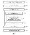
図6は、較正点に対するオフセットを決定するための例示的な流れ図を示す。 FIG. 6 shows an exemplary flow chart for determining an offset for a calibration point.
610において、較正点のパターンが決定される。較正点の数及び配置は、上述のように、補正された注視点を受信するターゲットアプリケーションの要件に依存し得る。 At 610, a calibration point pattern is determined. The number and placement of calibration points may depend on the requirements of the target application that receives the corrected gaze point, as described above.
ループ620〜630は較正点ごとに実行される。622において、較正点が照明され、ユーザは各照明された点を注視するように指示されている。624において、注視追跡デバイスは、ユーザが注視しているディスプレイ上の点に対応する注視点を提供する。上記で詳述されたように、いくつかのこれらの注視点が記録され、照明が停止し626、630において次の較正点について処理が反復される。 Loops 620-630 are executed for each calibration point. At 622, the calibration points are illuminated and the user is instructed to gaze at each illuminated point. At 624, the gaze tracking device provides a gaze point corresponding to a point on the display that the user is gazes at. As detailed above, several of these points of interest are recorded, illumination is stopped, and the process is repeated for the next calibration point at 626,630.
注視点が較正点ごとに収集された後、各較正点のこれらの注視点がループ640〜650において処理されて、較正点ごとに較正オフセットが決定される。 After a point of interest is collected for each calibration point, these points of interest for each calibration point are processed in loops 640-650 to determine a calibration offset for each calibration point.
642において、較正点に対応する各記録された注視点に関連する注視誤差が、記録された注視点と較正点の位置との間の距離に基づいて決定される。 At 642, a gaze error associated with each recorded gaze point corresponding to the calibration point is determined based on the distance between the recorded gaze point and the position of the calibration point.
644において、較正点についての記録された注視点の複合体に対応する測定された点が、決定された誤差に基づいて決定される。上記のように、この測定された点は、各注視点の二乗誤差の総和を最小化する位置とすることができるが、他の技法を適用して測定された点を決定することができる。 At 644, a measured point corresponding to the recorded gaze complex for the calibration point is determined based on the determined error. As described above, this measured point can be a position that minimizes the sum of the squared error of each gaze point, but other techniques can be applied to determine the measured point.
646において、較正点からの測定された点のオフセットが、この較正点に関連するオフセットとして決定及び記憶され、較正点のそれぞれに対するオフセットが決定されるまで処理が反復される650。 At 646, the measured point offset from the calibration point is determined and stored as an offset associated with the calibration point, and the process is repeated 650 until an offset for each of the calibration points is determined.
当業者であれば、2つのループ220〜230及び240〜250を1つのループ220〜250に結合し、その中で、較正点に関連するオフセットが決定された後に次の較正点が照明されるようにすることができることを理解するであろう。 A person skilled in the art combines the two loops 220-230 and 240-250 into one loop 220-250, in which the next calibration point is illuminated after the offset associated with the calibration point is determined. You will understand that you can.
図7は、図6の較正処理が完了した後に注視追跡デバイスにより提供される注視点を補正するための例示的な流れ図を示す。 FIG. 7 shows an exemplary flow chart for correcting a gaze point provided by a gaze tracking device after the calibration process of FIG. 6 is completed.
710において、いくつかの異なる較正データのセットが注視補正要素によりアクセス可能であると仮定すると、処理は、ユーザ、注視追跡デバイス、及びディスプレイを識別して、この構成に対応する較正データにアクセスすることができる。所与の注視追跡デバイス及びディスプレイ(又はその等価物)を用いてユーザの注視が較正されていない場合、注視補正要素を使用する前にこの較正を実施するようにユーザに指示することができる。 Assuming at 710 that several different sets of calibration data are accessible by the gaze correction element, the process identifies the user, gaze tracking device, and display to access the calibration data corresponding to this configuration. be able to. If the user's gaze is not calibrated with a given gaze tracking device and display (or equivalent), the user can be instructed to perform this calibration before using the gaze correction element.
720において、ユーザの現在の注視点が注視追跡デバイスから受信され、730において、現在の注視点が位置するゾーンが特定される。留意すべき重要なことは、補正要素が、較正処理で使用された想定されたゾーンとは異なるゾーンを規定できることである。すなわち、較正点は表示エリアの特定の分割を与えるように配置され得るが、その分割は、補正要素が選択可能な分割とは独立している。 At 720, the user's current gaze point is received from the gaze tracking device, and at 730, the zone in which the current gaze point is located is identified. It is important to note that the correction element can define a different zone than the assumed zone used in the calibration process. That is, the calibration points can be arranged to give a specific division of the display area, but that division is independent of the division from which the correction element can be selected.
740において、注視点の決定されたゾーンに関する各較正点の位置及びオフセットが取得される。上記のように、注視較正要素は、位置及びオフセットを注視補正要素によりアクセス可能なメモリに記憶することができ、又はこの情報を、注視補正要素からの要求に応答して提供することができる。 At 740, the position and offset of each calibration point with respect to the determined zone of interest is obtained. As described above, the gaze calibration element can store the position and offset in a memory accessible by the gaze correction element, or can provide this information in response to a request from the gaze correction element.
750において、注視点に適用される補正オフセットが決定される。上記のように、様々な技法のいずれかを適用して、このオフセットをゾーンの較正点に関連するオフセットに基づいて決定することができる。 At 750, a correction offset applied to the point of interest is determined. As described above, any of a variety of techniques can be applied to determine this offset based on the offset associated with the calibration point of the zone.
いくつかの実施形態では、注視補正要素は、複数の補正技法を含むように構成し、典型的には補正された注視点を使用するアプリケーションのニーズに応じた特定の補正技法の選択を可能にするように構成することができる。上記のように、注視されているディスプレイ上の「ボタン」を決定するだけでよいアプリケーションは、「最近傍」補間によって対処される。また、補正技法の選択は較正点のパターンに依存してもよく、その理由は、補正技法の中には、その技法により使用される点の配置に制約を加えるものがあるためである。いくつかの実施形態では、注視補正要素は、較正点の所与のパターンに基づいて「デフォルト」の補正技法を選択するように構成することができ、これは特に所与のパターンのために利用可能な「より良い」(より高速、より正確などの)技法が存在する場合である。 In some embodiments, the gaze correction element is configured to include multiple correction techniques, typically allowing the selection of a specific correction technique depending on the needs of the application that uses the corrected gaze point. Can be configured to. As mentioned above, applications that only need to determine the “button” on the display being watched are addressed by “nearest neighbor” interpolation. Also, the choice of correction technique may depend on the pattern of calibration points because some correction techniques place constraints on the placement of points used by the technique. In some embodiments, the gaze correction element can be configured to select a “default” correction technique based on a given pattern of calibration points, which is particularly useful for a given pattern. This is the case when there are possible “better” techniques (faster, more accurate, etc.).
上記のように、機械学習要素は、オフセットを特定する中間ステップなしで、補正された座標を生成するように訓練することができる。しかしながら、処理はオフセットを効果的に決定して、入力注視点を所与の量だけ注視点からオフセットされた補正された注視点に変換するようにする。 As described above, the machine learning element can be trained to generate corrected coordinates without an intermediate step of identifying the offset. However, the process effectively determines the offset and converts the input gaze point to a corrected gaze point that is offset from the gaze point by a given amount.
760において、決定されたオフセットが入力注視点に適用され、770において、補正された注視点がアプリケーションに伝達される。補正要素が補正された注視点をアプリケーションに継続的又はほぼ継続的に送信する「プッシュ」技法、及びアプリケーションが補正された注視点を要求し補正要素がこれを提供する「プル」技法として一般的に区別される様々な技法のいずれかを用いて、補正された注視点をアプリケーションに伝達することができる。いくつかの実施形態では、補正要素は、1つ又は複数のメモリ位置を継続的に更新するように構成することができ(たとえば、環状バッファ)、アプリケーションは、最も直近の補正された注視点を必要とする度に、このメモリにアクセスするように構成される。 At 760, the determined offset is applied to the input gaze point, and at 770, the corrected gaze point is communicated to the application. Commonly used as a “push” technique in which a correction element sends a corrected gaze point to the application continuously or nearly continuously, and a “pull” technique in which the application requests a corrected gaze point and provides it Any of a variety of techniques can be used to communicate the corrected gaze point to the application. In some embodiments, the correction element can be configured to continually update one or more memory locations (eg, a circular buffer) so that the application can determine the most recent corrected gaze point. It is configured to access this memory whenever it is needed.
上記のように、局所化された平滑化関数を適用して、ユーザの注視点の決定に関連するノイズを軽減することができる。そのようなノイズは、ユーザが所与のターゲットを注視するときの、ユーザの注視の実際の変化である場合があり、又はユーザの注視を検出するために使用されるセンサに関連するノイズ、若しくは他の要因である場合もある。この発明のいくつかの実施形態では、ノイズ較正処理を適用して、複数のノイズゾーンのそれぞれについて報告された注視点のシーケンスを最良に平滑化する関数を決定する。続いて、ユーザが特定のノイズ較正ゾーン内を注視しているときに、この関数が報告された注視点のシーケンスに適用される。 As described above, a localized smoothing function can be applied to reduce noise associated with the determination of the user's point of interest. Such noise may be an actual change in the user's gaze when the user gazes a given target, or noise associated with a sensor used to detect the user's gaze, or There can be other factors. In some embodiments of the invention, a noise calibration process is applied to determine a function that best smoothes the reported sequence of points of interest for each of the plurality of noise zones. Subsequently, this function is applied to the reported sequence of gazing points as the user is gazing within a particular noise calibration zone.
一例示的実施形態では、ノイズ較正要素は図2の注視較正要素250に含まれ、ノイズ平滑化要素は注視補正要素270に含まれる。以下で詳述される例示的実施形態では、これらのノイズ要素のそれぞれは、注視補正要素内のオフセット補正要素から誤差補正された注視点を受信し、アプリケーション280に提供される注視補正要素270の出力は、平滑化された誤差補正された注視点である。他の構成は、この開示を鑑みれば当業者には明白であろう。
In one exemplary embodiment, the noise calibration element is included in the
図8は、ノイズ較正ゾーンについてのノイズ平滑化関数を決定するための例示的な流れ図を示す。 FIG. 8 shows an exemplary flow diagram for determining a noise smoothing function for a noise calibration zone.
810において、ノイズ較正ゾーンが、対応するノイズ較正点と共に規定される。これらのノイズ較正ゾーン及びノイズ較正点は、誤差補正ゾーン320及び較正点310に対応してもよく、異なってもよい。たとえば、ノイズ較正ゾーンは、他のノイズ較正ゾーンに囲まれたディスプレイの中心エリアを含むことができ、たとえば、N×Nのノイズ較正ゾーンのセットにより与えられるものであり、ここでNは奇数である。
At 810, a noise calibration zone is defined with a corresponding noise calibration point. These noise calibration zones and noise calibration points may correspond to the
ノイズ較正点を誤差補正較正点310と同じものにして、別個のノイズ較正運動を行う必要性を回避することができる。ノイズ較正ゾーンは、誤差補正較正点310の1つのみ、たとえば規定されたノイズ較正ゾーンの中心付近の較正点310などに関連付けることができ、若しくはそのゾーン内の誤差補正較正点310の全てに関連付けることができ、又は任意の他の有意義な選択とすることができる。
The noise calibration point can be the same as the error
820において、平滑化関数の形式が規定される。従来の平滑化関数は、過去のM個の報告された注視点の加重平均を使用することが多く、重みは、より直近に報告された注視点ほど高く、古い点ほど低い。M及び使用される特定の重みの選択は、フィルタリング/平滑化関数の形状を規定する。Mの値が大きいと、平滑化された注視点を提供する際にラグが導入され、その理由は、平滑化された注視点が提供され得る前に、M個の注視点の全てが収集される必要があるためである。重みの「傾き」はユーザが注視点を変更したときのシステムの応答性を決定する。より古い注視点が大きい重みを有する場合、平滑化された注視点は、新たな注視点と古い注視点との間のどこかに配置され、ユーザが新たな注視点を注視している間にM個の点全てが収集されたときに、新たな注視点に「追いつく」。 At 820, the form of the smoothing function is defined. Conventional smoothing functions often use a weighted average of the past M reported gazing points, with the weights being higher for the most recently reported gazing points and lower for the older points. The choice of M and the particular weight used defines the shape of the filtering / smoothing function. A large value of M introduces a lag in providing a smoothed gaze point because all of the M gaze points are collected before a smoothed gaze point can be provided. This is because it is necessary to The “slope” of the weight determines the responsiveness of the system when the user changes the gaze point. If the older watch point has a large weight, the smoothed watch point is placed somewhere between the new watch point and the old watch point, while the user is watching the new watch point. When all M points are collected, “catch up” to a new point of interest.
一例示的実施形態では、平滑化関数の形式は加重平均とすることができ、以前の注視点のそれぞれに適用される重み(係数)は、ノイズ較正ゾーンごとに個別に決定することができる。他の実施形態では、平滑化関数は、較正注視点を平滑化された注視点に最良に一致させるように曲線適合される多項式とすることができる。較正注視点を決定された平滑化された注視点に最良に一致させる関数のパラメータを決定する他の手段は、当業者には明白であろう。 In one exemplary embodiment, the form of the smoothing function can be a weighted average, and the weight (coefficient) applied to each of the previous gaze points can be determined individually for each noise calibration zone. In other embodiments, the smoothing function may be a polynomial that is curve-fitted to best match the calibration gaze to the smoothed gaze. Other means of determining the parameters of the function that best matches the calibration gaze to the determined smoothed gaze will be apparent to those skilled in the art.
特に留意されたいのは、以下でさらに詳述されるように、平滑化関数が人工ニューラルネットワークなどの機械学習要素において具現化できることである。 Of particular note is that smoothing functions can be implemented in machine learning elements such as artificial neural networks, as will be described in more detail below.
ループ830〜840はノイズ較正ゾーンごとに平滑化関数を決定し、この例示的実施形態では、平滑化関数の形式は各ゾーン内で同一であり、課題は、各ノイズ平滑化ゾーン内の関数の特定の係数を発見することである。他の実施形態では、異なる形式の平滑化関数を、異なるノイズ平滑化ゾーンに対して規定することができる。 Loops 830-840 determine a smoothing function for each noise calibration zone, and in this exemplary embodiment, the form of the smoothing function is the same within each zone, and the task is to determine the function of each noise smoothing zone. To find a specific coefficient. In other embodiments, different types of smoothing functions may be defined for different noise smoothing zones.
各ゾーンに関連付けられた誤差補正較正点の全てがループ832〜838で処理されて、835において、結果の各平滑化された注視点を較正点に最も適合させる平滑化関数の係数(又は他のパラメータ)が決定される。そのような最も適合する係数のセットを規定するために、最小二乗誤差総和の技法が一般的に使用されている。一例示的実施形態では、誤差補正要素からの補正された注視点を用いて、ディスプレイ上での各較正点の位置に対する平滑化された注視点の誤差を決定する。 All of the error correction calibration points associated with each zone are processed in loops 832-838 and at 835 the smoothing function coefficients (or other factors) that best fit each smoothed gaze point of the results to the calibration points. Parameter) is determined. In order to define such a set of best fit coefficients, the least square error summation technique is commonly used. In one exemplary embodiment, the corrected gaze point from the error correction element is used to determine a smoothed gaze point error for each calibration point location on the display.
機械学習要素が使用される場合、M個の誤差補正された点が訓練段階中の機械学習要素への入力として与えられ、対応する誤差補正較正点の位置が所望の/正しい出力となる。M個の誤差補正された点の各セットが所与のノイズ較正ゾーンに対して提供されると、機械学習要素はその内部パラメータ(たとえば、ニューラルネットワーク内のノードに関連する重み)を調整して、所望の/正しい出力に最も一致する出力を提供するようにする。 If a machine learning element is used, M error-corrected points are provided as inputs to the machine learning element during the training phase, and the position of the corresponding error correction calibration point is the desired / correct output. As each set of M error-corrected points is provided for a given noise calibration zone, the machine learning element adjusts its internal parameters (eg, weights associated with nodes in the neural network) To provide the output that best matches the desired / correct output.
850において、ノイズ較正ゾーンごとのノイズ平滑化係数、又は訓練された機械学習要素が、補正された注視点を平滑化する注視補正システム内の要素に提供される。各誤差補正ゾーンに対して提供されるオフセットと同様に、これらのノイズ較正パラメータのノイズ平滑化要素への伝達は、これらのパラメータを明示的に伝送することによって、又はこれらのパラメータをノイズ平滑化要素がアクセス可能なメモリに記憶することによって実現することができる。 At 850, a noise smoothing factor for each noise calibration zone, or a trained machine learning element, is provided to an element in the gaze correction system that smoothes the corrected gaze point. Similar to the offset provided for each error correction zone, the transmission of these noise calibration parameters to the noise smoothing element can be done by explicitly transmitting these parameters or by smoothing these parameters. This can be achieved by storing the elements in accessible memory.
この発明の他の例示的実施形態では、Mの値はノイズ較正ゾーンごとに動的に決定することができる。すなわち、たとえば、特定のノイズ較正ゾーンについての平滑化関数は、最初は低いMの値、たとえば3などを有するものと規定することができる。平滑化関数の最も適合するパラメータは、この特定のノイズ較正ゾーン内の関連付けられた較正点について利用可能な補正された注視点の全てに対してこの低いMの値を用いることによって決定することができ、又は機械学習要素は、M個の補正された注視点を入力として用いて訓練することができ、各平滑化された注視点とその対応する較正点との差の分散を決定することができる。分散が所与の閾値未満である場合、このMの値を、この特定のゾーンに関連付けられた平滑化関数に使用することができる。分散がこの閾値を超える場合、Mの値を増加させ、決定された分散が閾値未満となるか又はMの最大値に達するまで、処理を反復させる。このように、たとえば、表示エリアの周囲よりも少ない平滑化点を表示エリアの中心で必要とすることによって、ディスプレイの中心付近を注視した場合に、より迅速な応答時間を提供することができる。 In other exemplary embodiments of the invention, the value of M can be determined dynamically for each noise calibration zone. That is, for example, the smoothing function for a particular noise calibration zone can initially be defined as having a low value of M, such as 3. The best fit parameter of the smoothing function may be determined by using this low M value for all of the corrected gaze points available for the associated calibration point in this particular noise calibration zone. Or the machine learning element can be trained using M corrected gaze points as inputs to determine the variance of the difference between each smoothed gaze point and its corresponding calibration point. it can. If the variance is less than a given threshold, this value of M can be used for the smoothing function associated with this particular zone. If the variance exceeds this threshold, the value of M is increased and the process is repeated until the determined variance is below the threshold or the maximum value of M is reached. In this way, for example, by requiring fewer smoothing points at the center of the display area than at the periphery of the display area, a quicker response time can be provided when the vicinity of the center of the display is watched.
図9は、上述のノイズ平滑化関数に基づいて補正された注視座標を平滑化するための例示的な流れ図を示す。 FIG. 9 shows an exemplary flowchart for smoothing gaze coordinates corrected based on the noise smoothing function described above.
この例示的実施形態では、平滑化関数は、910におけるM個の補正された注視点の受信に基づいて規定され、ここでMは全てのノイズ較正ゾーンで同一であり、Mが特定のノイズ較正ゾーンに基づいて変化する場合、ステップ910及び920の順序は逆にすることができる。
In this exemplary embodiment, the smoothing function is defined based on the reception of M corrected gaze points at 910, where M is the same in all noise calibration zones and M is a specific noise calibration. When changing based on zones, the order of
920において、ノイズ較正ゾーンは、典型的には最も直近に受信された補正された注視点に基づいて決定される。930において、このノイズ較正ゾーンについての決定されたノイズ平滑化パラメータにアクセスされ、940において、これらのパラメータを有する平滑化関数、又はこのゾーンについての訓練された機械学習要素が、M個の最も直近の補正された注視点に適用される。 At 920, the noise calibration zone is typically determined based on the most recently received corrected gaze point. At 930, the determined noise smoothing parameters for this noise calibration zone are accessed, and at 940, the smoothing function with these parameters, or the trained machine learning element for this zone, is the M most recent Applied to the corrected gaze point.
次いで、950において、平滑化された補正された注視点が、明示的な通信又は共通メモリへのアクセスを介してアプリケーションに伝達される。 Then, at 950, the smoothed corrected gaze point is communicated to the application via explicit communication or access to a common memory.
本発明について図面及び前述の説明において詳細に図示し、説明したが、そのような図示及び説明は説明的又は例示的であって限定的ではないとみなされるべきであり、本発明は開示された実施形態に限定されない。 While the invention has been illustrated and described in detail in the drawings and foregoing description, such illustration and description are to be considered illustrative or exemplary and not restrictive, and the invention has been disclosed; It is not limited to the embodiment.
たとえば、対称性の直線的な配置の較正点が図3〜図5に図示されているが、当業者であれば、他の配置が実現可能な実施形態において本発明を動作させることが可能であることを認識するであろう。たとえば、較正点は、ディスプレイの外周に向けて密度を高くし、ディスプレイの中心付近で密度を低くすることができる。いくつかの実施形態では、較正点は、規則的なパターン(等しい大きさのゾーン)若しくは半規則的なパターン(規則的なパターンで配置された不均等な大きさのゾーンのグループ)で配置された「タイル状の」三角形又は他のポリゴンの頂点とすることができる。いくつかの実施形態では、較正点のパターンは、2つの変数における全次多項式補間に最適であることが知られている「Padua点」に対応することができる。 For example, symmetric linearly arranged calibration points are illustrated in FIGS. 3-5, but those skilled in the art can operate the invention in embodiments where other arrangements are feasible. You will recognize that there is. For example, the calibration points can increase in density toward the outer periphery of the display and decrease in density near the center of the display. In some embodiments, the calibration points are arranged in a regular pattern (equally sized zones) or a semi-regular pattern (group of unequal sized zones arranged in a regular pattern). It can also be a “tile” triangle or the apex of another polygon. In some embodiments, the pattern of calibration points may correspond to “Padua points” that are known to be optimal for all-order polynomial interpolation in two variables.
同様に、これらの例は較正点が選択的に「照明」されるべきであることを示しているが、当業者であれば、様々な技法のいずれかを用いて較正処理中にユーザが注視すべき較正点を目立たせることができることを認識するであろう。たとえば、ディスプレイの背景を白にすることができ、較正点がオフにされて、黒い点が生成される。同様に、較正点の形状によって、ユーザが注視すべき較正点を目立たせることができる。 Similarly, although these examples show that calibration points should be selectively “illuminated”, one of ordinary skill in the art can use any of a variety of techniques to monitor the user during the calibration process. It will be appreciated that the calibration points to be made can be highlighted. For example, the display background can be white and the calibration point is turned off to produce a black dot. Similarly, the shape of the calibration points can make the calibration points to be watched by the user stand out.
同様に、アプリケーションでの動作前に適用される特定の較正処理が開示されているが、当業者であれば、アプリケーションが使用された後に動的な較正処理を適用できることを認識するであろう。たとえば、アプリケーションは、ユーザがディスプレイ上の特定の「ボタン」を選択したときを示すフィードバックを提供することができ、選択されたボタンがユーザが選択しようとしたボタンであったという理解の下でアプリケーションを続行する。動的な較正処理は、選択されたボタンの座標を較正位置と解釈し、次いで、このボタン選択と同時にいくつかの報告された注視位置を検索して、オフセット補正及び/又はノイズ平滑化パラメータを決定及び/又は精緻化する。 Similarly, while specific calibration processes are disclosed that are applied prior to operation in the application, those skilled in the art will recognize that a dynamic calibration process can be applied after the application is used. For example, the application can provide feedback indicating when the user has selected a particular “button” on the display, with the understanding that the selected button was the button that the user attempted to select. To continue. The dynamic calibration process interprets the coordinates of the selected button as a calibration position and then searches several reported gaze positions simultaneously with this button selection to determine the offset correction and / or noise smoothing parameters. Determine and / or refine.
開示された実施形態に対する他の変形は、図面、開示及び添付の特許請求の範囲を研究することから、特許請求された発明を実施する際に、当業者により理解され達成され得る。特許請求の範囲において、「備える」という単語は他の要素又はステップを排除するものではなく、不定冠詞「a」又は「an」は複数を排除するものではない。単一のプロセッサ又は他のユニットは、特許請求の範囲に列挙されたいくつかの項目の機能を果たすことができる。特定の方策が相異なる従属請求項に列挙されているという単なる事実は、これらの方策の組合せが有利に使用できないことを示すものではない。コンピュータプログラムは、他のハードウェアと一緒に又はその一部として供給される光記憶媒体又は固体媒体などの適切な媒体上に記憶/配布することができるが、インターネット又は他の有線若しくは無線の電気通信システムを介するなど、他の形態で配布することもできる。特許請求の範囲におけるいかなる参照符号も、その範囲を限定するものとして解釈されるべきではない。 Other variations to the disclosed embodiments can be understood and achieved by those skilled in the art in practicing the claimed invention, from studying the drawings, the disclosure, and the appended claims. In the claims, the word “comprising” does not exclude other elements or steps, and the indefinite article “a” or “an” does not exclude a plurality. A single processor or other unit may fulfill the functions of several items recited in the claims. The mere fact that certain measures are recited in different dependent claims does not indicate that a combination of these measures cannot be used to advantage. The computer program may be stored / distributed on any suitable medium, such as an optical storage medium or solid medium supplied with or as part of other hardware, but may be internet or other wired or wireless electrical It can also be distributed in other forms, such as via a communication system. Any reference signs in the claims should not be construed as limiting the scope.
Claims (14)
当該注視追跡システムはノイズ平滑化関数の較正要素を備え、
前記ノイズ平滑化関数の較正要素は、
各ノイズ較正ゾーンが1つ又は複数のノイズ較正位置を含む、複数のノイズ較正ゾーンに前記表示エリアを分割し、
ノイズ較正ゾーンごとに、前記ノイズ較正ゾーンについてのノイズ平滑化関数を、ユーザが各ノイズ較正位置を注視している間の複数の注視位置に基づいて決定し、
前記ノイズ平滑化要素は、
複数の後続の注視位置を受信し、
特定のノイズ較正ゾーンを前記後続の注視位置の少なくとも1つに基づいて決定し、
前記特定のノイズ較正ゾーンについての前記ノイズ平滑化関数を前記複数の後続の注視位置に適用して、平滑化された注視位置を決定し、
前記平滑化された注視位置をアプリケーションに伝達することを特徴とする、
注視追跡システム。 A gaze tracking device for identifying the position on the display area based on the user's gaze, the gaze tracking system and a noise smoothing element,
The gaze tracking system includes a noise smoothing function calibration element;
Calibration elements of the noise smoothing function,
Dividing the display area into a plurality of noise calibration zones, each noise calibration zone including one or more noise calibration locations;
For each noise calibration zone, a noise smoothing function for the noise calibration zone is determined based on a plurality of gaze positions while the user gazes at each noise calibration position;
The noise smoothing element is:
Receive multiple subsequent gaze positions,
Determining a specific noise calibration zone based on at least one of the subsequent gaze positions;
Applying the noise smoothing function for the particular noise calibration zone to the plurality of subsequent gaze positions to determine a smoothed gaze position;
Transmitting the smoothed gaze position to an application ,
Gaze tracking system.
注視補正要素と
を更に備え、
前記注視較正要素は、
複数の較正位置を規定し、
較正位置ごとに、
前記ユーザが前記較正位置を注視したときの前記表示エリア上の1つ又は複数の報告された位置を前記注視追跡デバイスから受信し、
前記較正位置に関連する位置誤差を、前記1つ又は複数の報告された位置と前記較正位置との差に基づいて決定し、
前記注視補正要素は、
各補正ゾーンが前記複数の較正位置の1つ又は複数を含む、複数の補正ゾーンに前記表示エリアを分割し、
補正ゾーンごとに、
前記補正ゾーンについての補正関数を、前記補正ゾーンの前記複数の較正位置の1つ又は複数における前記位置誤差に基づいて決定し、
前記注視追跡デバイスにより提供される後続の注視位置を受信し、
前記後続の注視位置に基づいて特定のゾーンを決定し、
前記特定のゾーンについての前記補正関数を前記後続の注視位置に適用して、補正された注視位置を決定し、
前記ノイズ平滑化要素により受信された前記複数の後続の注視位置は、前記注視補正要素によって補正された注視位置のセットであり、較正ゾーンのそれぞれについてのノイズ平滑化関数を決定するために前記ノイズ平滑化関数の較正要素により用いられる前記複数の注視位置は、前記注視補正要素により補正された注視位置のセットである、
請求項1に記載の注視追跡システム。 Gaze calibration elements;
A gaze correction element ,
The gaze calibration element is
Define multiple calibration positions,
For each calibration position,
Receiving from the gaze tracking device one or more reported positions on the display area when the user gazes at the calibration position;
The position error associated with calibration position, determined based on the difference between said one or a plurality of reported position and the calibration position,
The gaze correction element is
Each correction zone comprises one or more of the plurality of calibration positions, by dividing the display area into a plurality of correction zones,
For each correction zone,
Determining a correction function for the correction zone based on the position error at one or more of the plurality of calibration positions of the correction zone;
Receiving a subsequent gaze position provided by the gaze tracking device,
Wherein determining the particular zone based on the subsequent gaze position,
By applying the correction function for the particular zone to the subsequent fixation position, to determine a corrected gaze position,
The plurality of subsequent gaze positions received by the noise smoothing element is a set of gaze positions corrected by the gaze correction element, and the noise to determine a noise smoothing function for each of the calibration zones The plurality of gaze positions used by the calibration element of the smoothing function is a set of gaze positions corrected by the gaze correction element ;
The gaze tracking system according to claim 1 .
Applications Claiming Priority (3)
| Application Number | Priority Date | Filing Date | Title |
|---|---|---|---|
| US201462092349P | 2014-12-16 | 2014-12-16 | |
| US62/092,349 | 2014-12-16 | ||
| PCT/IB2015/059390 WO2016097919A1 (en) | 2014-12-16 | 2015-12-07 | Gaze tracking system with calibration improvement, accuracy compensation, and gaze localization smoothing |
Publications (3)
| Publication Number | Publication Date |
|---|---|
| JP2017537730A JP2017537730A (en) | 2017-12-21 |
| JP2017537730A5 JP2017537730A5 (en) | 2019-01-24 |
| JP6495457B2 true JP6495457B2 (en) | 2019-04-03 |
Family
ID=55022632
Family Applications (1)
| Application Number | Title | Priority Date | Filing Date |
|---|---|---|---|
| JP2017532006A Active JP6495457B2 (en) | 2014-12-16 | 2015-12-07 | Gaze tracking system with improved calibration, accuracy compensation, and gaze localization smoothing |
Country Status (5)
| Country | Link |
|---|---|
| US (1) | US10496160B2 (en) |
| EP (1) | EP3234737B1 (en) |
| JP (1) | JP6495457B2 (en) |
| CN (1) | CN107106007B (en) |
| WO (1) | WO2016097919A1 (en) |
Families Citing this family (28)
| Publication number | Priority date | Publication date | Assignee | Title |
|---|---|---|---|---|
| DE112014007127T5 (en) * | 2014-11-03 | 2017-09-21 | Bayerische Motoren Werke Aktiengesellschaft | Method and system for calibrating an eye-tracking system |
| US11023038B2 (en) * | 2015-03-05 | 2021-06-01 | Sony Corporation | Line of sight detection adjustment unit and control method |
| RU2596062C1 (en) * | 2015-03-20 | 2016-08-27 | Автономная Некоммерческая Образовательная Организация Высшего Профессионального Образования "Сколковский Институт Науки И Технологий" | Method for correction of eye image using machine learning and method of machine learning |
| US10466780B1 (en) * | 2015-10-26 | 2019-11-05 | Pillantas | Systems and methods for eye tracking calibration, eye vergence gestures for interface control, and visual aids therefor |
| CN108463787B (en) | 2016-01-05 | 2021-11-30 | 瑞尔D斯帕克有限责任公司 | Gaze correction of multi-perspective images |
| EP4009147A1 (en) * | 2016-09-20 | 2022-06-08 | Tobii AB | Gaze and saccade based graphical manipulation |
| JP2019017988A (en) * | 2017-07-18 | 2019-02-07 | 富士通株式会社 | Sightline position detection program, sightline position detection apparatus, and sightline position detection method |
| EP4293574A3 (en) | 2017-08-08 | 2024-04-03 | RealD Spark, LLC | Adjusting a digital representation of a head region |
| CN108038884B (en) * | 2017-11-01 | 2020-12-11 | 北京七鑫易维信息技术有限公司 | Calibration method, calibration device, storage medium and processor |
| US11346833B2 (en) * | 2018-01-17 | 2022-05-31 | Schlumberger Technology Corporation | Reservoir fluid characterization system |
| US11393251B2 (en) | 2018-02-09 | 2022-07-19 | Pupil Labs Gmbh | Devices, systems and methods for predicting gaze-related parameters |
| WO2019154509A1 (en) | 2018-02-09 | 2019-08-15 | Pupil Labs Gmbh | Devices, systems and methods for predicting gaze-related parameters |
| WO2019154511A1 (en) | 2018-02-09 | 2019-08-15 | Pupil Labs Gmbh | Devices, systems and methods for predicting gaze-related parameters using a neural network |
| US11017575B2 (en) | 2018-02-26 | 2021-05-25 | Reald Spark, Llc | Method and system for generating data to provide an animated visual representation |
| CN108259887B (en) * | 2018-04-13 | 2020-01-31 | 宁夏大学 | Method and device for calibrating fixation point and method and device for calibrating fixation point |
| CN108969930B (en) * | 2018-06-25 | 2023-09-15 | 中国人民解放军火箭军工程大学 | Aiming device and aiming method for rotor unmanned aerial vehicle fire extinguishing bomb system |
| EP3605287A1 (en) * | 2018-07-31 | 2020-02-05 | Nokia Technologies Oy | An apparatus, method and computer program for adjusting output signals |
| TWI704501B (en) * | 2018-08-09 | 2020-09-11 | 宏碁股份有限公司 | Electronic apparatus operated by head movement and operation method thereof |
| US11537202B2 (en) | 2019-01-16 | 2022-12-27 | Pupil Labs Gmbh | Methods for generating calibration data for head-wearable devices and eye tracking system |
| US11676422B2 (en) | 2019-06-05 | 2023-06-13 | Pupil Labs Gmbh | Devices, systems and methods for predicting gaze-related parameters |
| US11347308B2 (en) * | 2019-07-26 | 2022-05-31 | Samsung Electronics Co., Ltd. | Method and apparatus with gaze tracking |
| CN113253829B (en) * | 2020-02-10 | 2022-05-06 | Oppo广东移动通信有限公司 | Eyeball tracking calibration method and related product |
| CN113395438B (en) * | 2020-03-12 | 2023-01-31 | Oppo广东移动通信有限公司 | Image correction method and related device for eyeball tracking technology |
| CN111399658B (en) * | 2020-04-24 | 2022-03-15 | Oppo广东移动通信有限公司 | Calibration method and device for eyeball fixation point, electronic equipment and storage medium |
| JP2022103717A (en) * | 2020-12-28 | 2022-07-08 | 株式会社Subaru | Slight line calibration system |
| SE545129C2 (en) * | 2021-03-31 | 2023-04-11 | Tobii Ab | Method and system for eye-tracker calibration |
| US11619993B2 (en) | 2021-04-19 | 2023-04-04 | Microsoft Technology Licensing, Llc | Systems and methods for gaze-tracking |
| US20220330863A1 (en) * | 2021-04-19 | 2022-10-20 | Microsoft Technology Licensing, Llc | Systems and methods of capturing eye-gaze data |
Family Cites Families (18)
| Publication number | Priority date | Publication date | Assignee | Title |
|---|---|---|---|---|
| US5913079A (en) * | 1995-07-31 | 1999-06-15 | Canon Kabushiki Kaisha | Optical apparatus having a line of sight detection device |
| US6351273B1 (en) * | 1997-04-30 | 2002-02-26 | Jerome H. Lemelson | System and methods for controlling automatic scrolling of information on a display or screen |
| US6152563A (en) * | 1998-02-20 | 2000-11-28 | Hutchinson; Thomas E. | Eye gaze direction tracker |
| US20090268045A1 (en) | 2007-08-02 | 2009-10-29 | Sudipto Sur | Apparatus and methods for configuration and optimization of image sensors for gaze tracking applications |
| ES2880475T3 (en) | 2009-04-01 | 2021-11-24 | Tobii Ab | Visual representation system with illuminators for gaze tracking |
| US9237844B2 (en) | 2010-03-22 | 2016-01-19 | Koninklijke Philips N.V. | System and method for tracking the point of gaze of an observer |
| US20120106793A1 (en) * | 2010-10-29 | 2012-05-03 | Gershenson Joseph A | Method and system for improving the quality and utility of eye tracking data |
| WO2012083415A1 (en) | 2010-11-15 | 2012-06-28 | Tandemlaunch Technologies Inc. | System and method for interacting with and analyzing media on a display using eye gaze tracking |
| EP2499963A1 (en) * | 2011-03-18 | 2012-09-19 | SensoMotoric Instruments Gesellschaft für innovative Sensorik mbH | Method and apparatus for gaze point mapping |
| TW201400084A (en) * | 2012-06-27 | 2014-01-01 | Yomiko Advertising Inc | Fixation line measuring method, fixation line measuring device, eyeball rotation center measuring device, and view point measuring device |
| JP5971061B2 (en) * | 2012-07-24 | 2016-08-17 | 株式会社Jvcケンウッド | Gaze point detection device, gaze point detection method, diagnosis support device, operation method and program for diagnosis support device |
| JP6014931B2 (en) * | 2012-09-06 | 2016-10-26 | 公立大学法人広島市立大学 | Gaze measurement method |
| EP2907453B1 (en) * | 2012-09-28 | 2018-11-21 | JVC Kenwood Corporation | Diagnosis assistance device and diagnosis assistance method |
| KR101438948B1 (en) | 2012-12-12 | 2014-09-11 | 현대자동차주식회사 | Apparatus and method for gaze tracking control |
| CN105027144A (en) * | 2013-02-27 | 2015-11-04 | 汤姆逊许可公司 | Method and device for calibration-free gaze estimation |
| GB2511868B (en) | 2013-03-15 | 2020-07-15 | Tobii Ab | Eye/gaze tracker and method of tracking the position of an eye and/or a gaze point of a subject |
| JP6123694B2 (en) * | 2014-02-10 | 2017-05-10 | ソニー株式会社 | Information processing apparatus, information processing method, and program |
| US9489739B2 (en) * | 2014-08-13 | 2016-11-08 | Empire Technology Development Llc | Scene analysis for improved eye tracking |
-
2015
- 2015-12-07 CN CN201580068833.4A patent/CN107106007B/en active Active
- 2015-12-07 WO PCT/IB2015/059390 patent/WO2016097919A1/en active Application Filing
- 2015-12-07 US US15/535,747 patent/US10496160B2/en active Active
- 2015-12-07 JP JP2017532006A patent/JP6495457B2/en active Active
- 2015-12-07 EP EP15816241.2A patent/EP3234737B1/en active Active
Also Published As
| Publication number | Publication date |
|---|---|
| EP3234737A1 (en) | 2017-10-25 |
| CN107106007A (en) | 2017-08-29 |
| JP2017537730A (en) | 2017-12-21 |
| CN107106007B (en) | 2020-10-02 |
| EP3234737B1 (en) | 2019-04-10 |
| US20170364149A1 (en) | 2017-12-21 |
| WO2016097919A1 (en) | 2016-06-23 |
| US10496160B2 (en) | 2019-12-03 |
Similar Documents
| Publication | Publication Date | Title |
|---|---|---|
| JP6495457B2 (en) | Gaze tracking system with improved calibration, accuracy compensation, and gaze localization smoothing | |
| US7657062B2 (en) | Self-calibration for an eye tracker | |
| US10650533B2 (en) | Apparatus and method for estimating eye gaze location | |
| US9811158B2 (en) | System and method for calibrating eye gaze data | |
| US9210417B2 (en) | Real-time registration of a stereo depth camera array | |
| US10016131B2 (en) | Eye tracking system and method to detect the dominant eye | |
| Marius't Hart et al. | Gaze allocation in natural stimuli: Comparing free exploration to head-fixed viewing conditions | |
| US11238340B1 (en) | Predictive eyetracking using recurrent neural networks | |
| KR20150122666A (en) | Method and device for calibration-free gaze estimation | |
| US11276225B2 (en) | Synthesizing an image from a virtual perspective using pixels from a physical imager array weighted based on depth error sensitivity | |
| Barz et al. | Error-aware gaze-based interfaces for robust mobile gaze interaction | |
| CN108875526A (en) | Method, apparatus, system and the computer storage medium of line-of-sight detection | |
| CN104302226A (en) | Video analysis device, video analysis method, and point-of-gaze display system | |
| Açık et al. | Real and implied motion at the center of gaze | |
| Rai et al. | Visual attention, visual salience, and perceived interest in multimedia applications | |
| Singh et al. | Bayesian contour extrapolation: Geometric determinants of good continuation | |
| US20200265598A1 (en) | SYSTEMS AND METHODS FOR HANDLING MULTIPLE SIMULTANEOUS LOCALIZATION AND MAPPING (SLAM) SOURCES AND ALGORITHMS IN VIRTUAL, AUGMENTED, AND MIXED REALITY (xR) APPLICATIONS | |
| Barz et al. | Computational modelling and prediction of gaze estimation error for head-mounted eye trackers | |
| US10521964B1 (en) | Switching among disparate simultaneous localization and mapping (SLAM) methods in virtual, augmented, and mixed reality (xR) applications | |
| KR102356599B1 (en) | Method for determining region of interest of image and device for determining region of interest of image | |
| Weigle et al. | Analysis of eye-tracking experiments performed on a Tobii T60 | |
| Boczon | State of the art: eye tracking technology and applications | |
| Calow et al. | Efficient encoding of natural optic flow | |
| CN111310627B (en) | Detection method and device of sensing device and electronic equipment | |
| EP3506055A1 (en) | Method for eye-tracking calibration with splash screen |
Legal Events
| Date | Code | Title | Description |
|---|---|---|---|
| A521 | Request for written amendment filed |
Free format text: JAPANESE INTERMEDIATE CODE: A523 Effective date: 20181206 |
|
| A621 | Written request for application examination |
Free format text: JAPANESE INTERMEDIATE CODE: A621 Effective date: 20181206 |
|
| A871 | Explanation of circumstances concerning accelerated examination |
Free format text: JAPANESE INTERMEDIATE CODE: A871 Effective date: 20181206 |
|
| A975 | Report on accelerated examination |
Free format text: JAPANESE INTERMEDIATE CODE: A971005 Effective date: 20190124 |
|
| TRDD | Decision of grant or rejection written | ||
| A01 | Written decision to grant a patent or to grant a registration (utility model) |
Free format text: JAPANESE INTERMEDIATE CODE: A01 Effective date: 20190205 |
|
| A61 | First payment of annual fees (during grant procedure) |
Free format text: JAPANESE INTERMEDIATE CODE: A61 Effective date: 20190306 |
|
| R150 | Certificate of patent or registration of utility model |
Ref document number: 6495457 Country of ref document: JP Free format text: JAPANESE INTERMEDIATE CODE: R150 |
|
| R250 | Receipt of annual fees |
Free format text: JAPANESE INTERMEDIATE CODE: R250 |
|
| R250 | Receipt of annual fees |
Free format text: JAPANESE INTERMEDIATE CODE: R250 |
|
| R250 | Receipt of annual fees |
Free format text: JAPANESE INTERMEDIATE CODE: R250 |