JP6494918B2 - Wireless communication system - Google Patents
Wireless communication system Download PDFInfo
- Publication number
- JP6494918B2 JP6494918B2 JP2014065856A JP2014065856A JP6494918B2 JP 6494918 B2 JP6494918 B2 JP 6494918B2 JP 2014065856 A JP2014065856 A JP 2014065856A JP 2014065856 A JP2014065856 A JP 2014065856A JP 6494918 B2 JP6494918 B2 JP 6494918B2
- Authority
- JP
- Japan
- Prior art keywords
- base station
- radio
- transmission
- station radio
- timing
- Prior art date
- Legal status (The legal status is an assumption and is not a legal conclusion. Google has not performed a legal analysis and makes no representation as to the accuracy of the status listed.)
- Active
Links
- 238000004891 communication Methods 0.000 title claims description 47
- 230000005540 biological transmission Effects 0.000 claims description 221
- 230000001360 synchronised effect Effects 0.000 claims description 9
- 230000008859 change Effects 0.000 claims description 4
- 238000000034 method Methods 0.000 description 21
- 230000008569 process Effects 0.000 description 15
- 238000012545 processing Methods 0.000 description 7
- 238000012544 monitoring process Methods 0.000 description 6
- 238000004088 simulation Methods 0.000 description 5
- 238000005562 fading Methods 0.000 description 4
- 238000013459 approach Methods 0.000 description 2
- 230000003111 delayed effect Effects 0.000 description 2
- 238000013461 design Methods 0.000 description 2
- 230000000694 effects Effects 0.000 description 2
- 230000004044 response Effects 0.000 description 2
- 230000015556 catabolic process Effects 0.000 description 1
- 238000006731 degradation reaction Methods 0.000 description 1
- 230000006870 function Effects 0.000 description 1
- 238000009434 installation Methods 0.000 description 1
- 230000002452 interceptive effect Effects 0.000 description 1
- 238000013508 migration Methods 0.000 description 1
- 230000005012 migration Effects 0.000 description 1
- 230000003287 optical effect Effects 0.000 description 1
- 230000005855 radiation Effects 0.000 description 1
- 230000007704 transition Effects 0.000 description 1
Images


Landscapes
- Mobile Radio Communication Systems (AREA)
Description
本発明は、複数の基地局無線装置からの同時送信において、同一運用波送信による干渉を抑制するデジタル無線システムに関する。 The present invention relates to a digital radio system that suppresses interference due to the same operating wave transmission in simultaneous transmission from a plurality of base station radio apparatuses.
従来のデジタル無線システムでは、複数の基地局無線装置による同一運用波の同時送信において、各基地局無線装置は、下位の無線端末装置に対する下り送信の開始指示を無線回線制御装置から受信したことを契機に各々のタイミングで開始するため、近隣の基地局無線装置の影響によって不感地帯が発生する可能性がある。 In the conventional digital radio system, in the simultaneous transmission of the same operating wave by a plurality of base station radio devices, each base station radio device has received from the radio network controller an instruction to start downlink transmission to a lower radio terminal device. Since it starts at each timing as an opportunity, there is a possibility that a dead zone may occur due to the influence of neighboring base station radio apparatuses.
すなわち、無線回線制御装置が下り送信の開始指示を各基地局無線装置に一斉に通知しても、下り送信の開始指示が各基地局無線装置に到達するタイミングは、無線回線制御装置との間の伝送時間の相違により、下り送信の開始指示が各基地局無線装置に到達するタイミングが異なってしまい、同時送信のはずが各基地局無線装置で異なるタイミングで実施されることになり得る。このため、複数の基地局無線装置からの無線信号が到達するエリア(基地局無線装置のサービスエリアが重複するエリア)では、複数の基地局無線装置によって異なるタイミングで開始された下り送信が相互に干渉しあって不感地帯が発生する可能性がある。 That is, even if the radio network controller notifies all base station radio devices of the downlink transmission start instruction, the timing at which the downlink transmission start instruction reaches each base station radio device is Due to the difference in transmission time, the timing at which a downlink transmission start instruction arrives at each base station radio apparatus differs, and simultaneous transmission should be performed at different timings at each base station radio apparatus. For this reason, in areas where radio signals from a plurality of base station radio apparatuses reach (areas where service areas of base station radio apparatuses overlap), downlink transmissions started at different timings by the plurality of base station radio apparatuses are mutually There may be a dead zone due to interference.
デジタル無線システムに関しては従来より種々の発明が提案されており、例えば、特許文献1には、通常時には独立して動作する複数の系のシステムを緊急時に有効利用できるようにした無線通信システムの発明が開示されている。
Various inventions have been proposed for digital radio systems. For example,
消防救急無線システムは、デジタル伝送等の通信ニーズの多様化に対応するため、平成28年5月31日までの期間において、150MHz帯を使用したアナログ通信方式から260MHz帯を使用したデジタル通信方式への移行が実施されている。デジタル無線システムを導入することで、秘匿性を向上させた通信や、データ伝送等の高度な通信が実現可能となる一方、デジタル通信方式で使用する260MHz帯の伝播距離は150MHz帯の1/2から1/3程度であるため、デジタル化に伴って多くの中継局の設置が必要となる。 In order to respond to diversification of communication needs such as digital transmission, the fire and emergency radio system will change from an analog communication system using the 150 MHz band to a digital communication system using the 260 MHz band in the period up to May 31, 2016. A migration has been implemented. By introducing a digital wireless system, communication with improved secrecy and advanced communication such as data transmission can be realized. On the other hand, the propagation distance of the 260 MHz band used in the digital communication method is 1/2 of the 150 MHz band. Therefore, it is necessary to install many relay stations with digitization.
ところが、中継局を増設する場合、サービスエリアが重複するエリアについては中継局の送信波が干渉する不感地帯が発生することから、アナログからデジタルへのシステム移行に際しては、不感地帯の解消が課題となっている。
また、現状システムのデジタル化への移行において、複数消防本部の合併に伴うシステムの広域化が進んでいる。システムが広域化することにより、各消防本部で広範囲のエリアを管轄することが求められるため、複数の基地局無線装置に跨った消防救急活動を行うことがある。このことから、不感地帯のエリア内での消防救急活動を行う機会が発生する懸念がある。
However, when adding more relay stations, there is a dead zone where the relay station's transmission waves interfere in areas where service areas overlap, so eliminating the dead zone is a challenge when migrating systems from analog to digital. It has become.
In addition, in the transition to the digitization of the current system, the system has become wider due to the merger of multiple firefighting headquarters. As the system becomes widespread, it is required that each fire-fighting headquarters has jurisdiction over a wide area, so fire-fighting emergency activities across multiple base station radio devices may be performed. For this reason, there is a concern that there will be an opportunity to conduct fire-fighting and emergency activities in the area of the dead zone.
上述したように、複数の基地局無線装置が無線回線制御装置からの開始指示を待って下り送信を開始するシステムでは、無線回線制御装置が下り送信の開始指示を各基地局無線装置に一斉に通知しても、無線回線制御装置との間の伝送時間が一律ではないので、各基地局無線装置が下り送信の開始指示を受信するタイミングは各々で異なってしまい、その結果、各基地局無線装置によって異なるタイミングで開始された下り送信が相互に干渉しあって不感地帯が発生する可能性がある。 As described above, in a system in which a plurality of base station radio devices start downlink transmission after waiting for a start instruction from the radio network controller, the radio network controller sends a downlink transmission start command to each base station radio device all at once. Even if the notification is made, the transmission time to and from the radio network controller is not uniform, so the timing at which each base station radio apparatus receives the downlink transmission start instruction is different, and as a result, each base station radio There is a possibility that a dead zone may occur due to interference between downlink transmissions started at different timings depending on devices.
本発明は、上記のような従来の事情に鑑みて為されたものであり、同一周波数を用いて下り送信を行う複数の基地局無線装置が、無線回線制御装置との間の伝送時間の相違に関わらず、互いに同じタイミングで下り送信を開始できるようにして、複数の基地局無線装置からの下り送信の相互干渉を抑制して不感地帯を低減させることを目的とする。 The present invention has been made in view of the above-described conventional circumstances, and a difference in transmission time between a plurality of base station radio apparatuses that perform downlink transmission using the same frequency and a radio network controller. Regardless, it is an object to reduce the dead zone by enabling the downlink transmission to be started at the same timing and suppressing the mutual interference of the downlink transmissions from a plurality of base station radio apparatuses.
本発明では、上記の目的を達成するために、同一周波数を用いて下り送信を行う複数の基地局と、前記複数の基地局無線装置を制御する無線回線制御装置と、を有する無線通信システムを、以下のように動作させることとした。 In order to achieve the above object, the present invention provides a radio communication system having a plurality of base stations that perform downlink transmission using the same frequency, and a radio network controller that controls the plurality of base station radio apparatuses. The operation was as follows.
すなわち、無線回線制御装置及び複数の基地局無線装置は、互いに同期したタイミングで動作し、無線回線制御装置は、複数の基地局無線装置に対して下り送信を同じタイミングで開始させる指示を送信するにあたり、当該指示における下り送信の開始タイミングとして、当該指示の送信タイミングに対して当該無線回線制御装置と複数の基地局無線装置との間の伝送時間の最大値分の間隔を置いたタイミングを設定することとした。
このような構成によれば、各基地局無線装置は、無線回線制御装置との間の伝送時間の相違に関わらず、互いに同じタイミングで下り送信を開始することができる。このため、複数の基地局無線装置からの下り送信が相互に干渉しあうことを抑制でき、不感地帯を低減させることができる。
That is, the radio network controller and the plurality of base station radio devices operate at timing synchronized with each other, and the radio network controller transmits an instruction to start downlink transmission at the same timing to the plurality of base station radio devices. In this case, as the start timing of downlink transmission in the instruction, a timing is set with an interval corresponding to the maximum transmission time between the radio network controller and the plurality of base station radio apparatuses with respect to the transmission timing of the instruction. It was decided to.
According to such a configuration, each base station radio apparatus can start downlink transmission at the same timing regardless of the difference in transmission time with the radio network controller. For this reason, it can suppress that the downlink transmission from a some base station radio | wireless apparatus mutually interferes, and can reduce a dead zone.
なお、複数の基地局無線装置及び無線回線制御装置を互いに同期したタイミングで動作させるには、例えば、以下のような構成とすればよい。
すなわち、複数の基地局無線装置及び無線回線制御装置は、それぞれ、GPS(Global Positioning System)衛星からの信号に基づいて1秒周期の基準信号と当該基準信号より短い周期のクロック信号とを出力するGPSモジュールを備え、基準信号をクロック信号に基づいて所定の整数で分割して無線フレームのタイミングを生成し、各無線フレームに基準信号のタイミングでリセットされるフレーム番号を付与する構成とする。
これにより、複数の基地局無線装置及び無線回線制御装置は、それぞれ独立に動作しながらも、他の装置と正確にフレームタイミング及びフレーム位置を同期させることができる。
In order to operate a plurality of base station radio devices and radio channel control devices at timings synchronized with each other, for example, the following configuration may be used.
That is, each of the plurality of base station radio devices and radio network controllers outputs a reference signal having a period of 1 second and a clock signal having a period shorter than that of the reference signal based on a signal from a GPS (Global Positioning System) satellite. A GPS module is provided, the reference signal is divided by a predetermined integer based on the clock signal, the timing of the radio frame is generated, and a frame number that is reset at the timing of the reference signal is given to each radio frame.
As a result, the plurality of base station radio devices and radio channel control devices can synchronize the frame timing and frame position with other devices accurately while operating independently.
ここで、一構成例として、無線回線制御装置は、複数の基地局無線装置の中に伝送時間が所定値以上の基地局無線装置が存在する場合に、伝送時間が前記所定値以内となる基地局無線装置に応じて下り送信を同じタイミングで開始させる指示を変更し、 該変更により設定された下り送信を同じタイミングで開始させる指示を送信することとする。
これにより、無線回線制御装置から遠すぎる基地局無線装置の存在によって、基地局無線装置に対する下り送信の開始指示の伝達が本来の予定より遅れてしまうことを防止できる。
Here, as one configuration example, when a base station radio apparatus having a transmission time equal to or greater than a predetermined value exists in a plurality of base station radio apparatuses, the radio network controller is configured to have a base whose transmission time is within the predetermined value An instruction to start downlink transmission at the same timing is changed according to the station radio apparatus, and an instruction to start downlink transmission set by the change at the same timing is transmitted.
Thereby, it is possible to prevent the transmission of the downlink transmission start instruction to the base station radio apparatus from being delayed from the original schedule due to the presence of the base station radio apparatus that is too far from the radio network controller.
また、一構成例として、複数の基地局無線装置は、下り送信の対象となるデータを受信してから所定時間が経過した場合には、指示を待たずに下り送信を開始することとする。
これにより、基地局無線装置において無線回線制御装置からの下り送信の開始指示を取り逃した結果、下り送信が開始されなくなる等の事態が発生することを回避できる。
Further, as one configuration example, a plurality of base station radio apparatuses start downlink transmission without waiting for an instruction when a predetermined time has elapsed after receiving data targeted for downlink transmission.
As a result, it is possible to avoid a situation in which downlink transmission is not started as a result of the base station radio apparatus missing the downlink transmission start instruction from the radio network controller.
本発明によれば、各基地局無線装置は、無線回線制御装置との間の伝送時間の相違に関わらず、互いに同じタイミングで下り送信を開始することができるため、複数の基地局無線装置からの下り送信が相互に干渉しあうことを抑制でき、不感地帯を低減させることができる。 According to the present invention, each base station radio apparatus can start downlink transmission at the same timing regardless of the transmission time difference with the radio network controller, so that a plurality of base station radio apparatuses can Can be prevented from interfering with each other, and the dead zone can be reduced.
本発明の一実施形態について図面を参照して説明する。
図1には、本発明の一実施形態に係る無線通信システムの概略構成の例を示してある。なお、本例では、無線通信システムの例として消防救急デジタル無線システムを用いるが、本発明は他の用途の無線通信システムにも適用することができる。
本例の無線通信システムは、無線統制台10、通信卓20、管理監視制御卓30、指令台40、指令制御装置50、無線回線制御装置60、基地局無線装置70、移動局無線装置90等の装置や設備を有している。
An embodiment of the present invention will be described with reference to the drawings.
FIG. 1 shows an example of a schematic configuration of a wireless communication system according to an embodiment of the present invention. In this example, a fire and emergency digital radio system is used as an example of a radio communication system, but the present invention can also be applied to a radio communication system for other purposes.
The wireless communication system of this example includes a
無線統制台10は、無線回線制御装置60に接続されて、消防車・救急車等の無線通信を集中制御する装置である。また、無線統制台10は、本部側に設置される設備であり、個別遠隔制御器の場合もある。
The
通信卓20は、無線回線制御装置60に接続されて、消防車・救急車等の無線通信を個々に行う装置である。また、通信卓20は、本部側に設置される設備であり、指令台40と統合的に併用される場合もある。これらは、各消防本部の使用の違いや、納入業者の装置設計方針の違いなどによって条件が異なる。
The
管理監視制御卓30は、無線回線制御装置60に接続されて、消防救急デジタル無線システムの運用管理及び監視制御等を行う装置である。管理監視制御卓30は、システム設計上の必要性により配置するものであり、存在しない場合もある。
The management
指令台40は、消防指令センターに設置され、指令制御装置50を介して無線回線制御装置60に接続されて、消防救急デジタル無線システムその他のシステムを操作するための装置であり、音声の入出力・データ(画像、車両の位置を示す情報等の非音声情報)・短文(最大80バイトの文字列)等の入力、処理、表示等を行う。
The
無線回線制御装置60には、上述したように、無線統制台10、通信卓20、管理監視制御卓30、指令台40が接続されている。
また、無線回線制御装置60には、その管理下にある複数の基地局無線装置70が接続されている。本例では、無線回線制御装置60に、無線チャネルf1を使用して移動局無線装置90(#1),(#2)との無線通信を行う基地局無線装置70(#1)〜(#3)と、無線チャネルf2を使用して移動局無線装置90(#3)との無線通信を行う基地局無線装置70(#4)と、無線チャネルf3を使用して移動局無線装置90(#4)との無線通信を行う基地局無線装置70(#5)が接続されており、これら基地局無線装置70の制御を行う。
As described above, the
The
移動局無線装置90は、車載や携帯により移動自在な無線通信端末であり、その所在位置をサービスエリア(無線通信エリア)に含む基地局無線装置70と無線通信を行う。ここで、基地局無線装置70(上位装置)から移動局無線装置90(下位装置)への無線通信を下り送信といい、その逆方向の無線通信を上り通信という。
なお、基地局無線装置70との無線通信を行う無線端末装置としては、上記のような移動局無線装置90のほか、固定的に設置された固定局無線装置を用いることもできる。
The mobile
As a wireless terminal device that performs wireless communication with the base
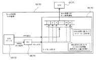
図2には、無線回線制御装置60の機能ブロックの例を示してある。
無線回線制御装置60は、GPSアンテナ61と、GPSモジュール63,PLL(Phase Locked Loop)64,スーパーフレームカウンタ65を備えたフレーム生成部62と、CPU(Central Processing Unit)67を備えた制御部66と、基地局インタフェース部68と、を有している。
なお、フレーム生成部62は、図3に示すように、GPSモジュール63,PLL64,スーパーフレームカウンタ65といった各ハードウェアモジュールをHUB基板に実装した構成となっている。
FIG. 2 shows an example of functional blocks of the
The
As shown in FIG. 3, the
GPSモジュール63は、GPS衛星から送信されてGPSアンテナ61により受信された信号に基づいて、10MHzクロック信号と1PPS(Pulse Per Second)信号を出力する。1PPS信号は、秒を刻むタイミングを示す1秒周期の矩形波信号である。
PLL64は、GPSモジュール63から出力される10MHzクロック信号に基づいて、40ms毎のフレームタイミングを示す40ms信号を出力する。
スーパーフレームカウンタ65は、PLL64から出力される40ms信号とGPSモジュール63から出力される1PPS信号とに基づいて、フレームタイミング(40ms周期)毎に、フレーム長40msの無線フレームを識別するフレーム番号を採番して制御部66のCPU67へ通知する。
The
The
Based on the 40 ms signal output from the
スーパーフレームカウンタ65の具体的な動作について、図3を参照して説明する。
スーパーフレームカウンタ65は、GPSモジュール63から出力される1PPS信号の周期(1秒周期)で切り替わるスーパーフレームを形成し、更に、PLL64から出力される40ms信号の周期でスーパーフレームを刻んで25個の無線フレームを形成する。このとき、各無線フレームに、スーパーフレーム内の位置(順序)を示す“1”〜“25”のフレーム番号を順番に付していく。フレーム番号の付与は、40ms信号の周期でインクリメント(+1)されるフレームカウンタを用いて行われる。このフレームカウンタは、スーパーフレームの切り替わり毎に初期値(本例では“1”)にリセットされる。
スーパーフレームカウンタ65で生成されたフレーム番号は、40ms周期のフレームタイミング毎に、制御部66のCPU67へ通知される。
A specific operation of the
The
The frame number generated by the
制御部66のCPU67は、指令台40等の装置から、下り送信の開始指示を受信すると、その時点(下り送信の開始指示の受信直前又は受信直後)にフレーム生成部62のスーパーフレームカウンタ65から通知されたフレーム番号に基づいて、基地局無線装置70が下り送信を開始する無線フレームのフレーム番号(以下、「送信タイミングフレーム番号」という)を設定する。
When the
ここで、送信タイミングフレーム番号は、無線回線制御装置60から基地局無線装置70までの伝送時間を考慮して設定することとする。
具体的には、無線回線制御装置60が下り送信の開始指示を基地局無線装置70へ送信するのに用いる無線フレームのフレーム番号(以下、「送信タイミング基底フレーム番号」という)を基準にして、送信タイミング基底フレーム番号に対して少なくとも伝送時間分の間隔を置いたフレーム番号を特定し、当該特定したフレーム番号を送信タイミングフレーム番号に設定する。すなわち、送信タイミング基底フレーム番号に、少なくとも伝送時間に相当する無線フレーム数を加算したフレーム番号を、送信タイミングフレーム番号に設定する。
Here, the transmission timing frame number is set in consideration of the transmission time from the
Specifically, based on the frame number of the radio frame used by the
本例では、各基地局無線装置70の設置後に無線回線制御装置60との間の伝送時間を測定し、測定値を所定時間単位(例えば100ms単位)で調整した結果を無線回線制御装置60のメモリに記憶させておき、送信タイミングフレーム番号を演算する際に参照する構成となっているが、伝送時間に相当する無線フレーム数を無線回線制御装置60のメモリに記憶させておき、送信タイミングフレーム番号を演算する際に参照する、等の他の構成により実現してもよい。
制御部66のCPU67で設定された送信タイミングフレーム番号は、下り送信の開始指示と共に、基地局インタフェース部68を介して基地局無線装置70へ送信される。
In this example, after the installation of each base
The transmission timing frame number set by the
図4を参照して、送信タイミング基底フレーム番号を基準にして送信タイミングフレーム番号を生成する処理を説明する。
図4には、上から順に、1PPS信号の波形の例、1PPS信号の波形の1周期(1秒)分を拡大した例、1PPS信号の1周期に相当する1スーパーフレームを整数値で分割して25個の無線フレーム(フレーム長40ms)を形成した例、無線回線制御装置60における送信タイミング基底フレーム番号の例、基地局無線装置70(#1)における送信タイミングフレーム番号の例を示してある。
図4の例では、無線回線制御装置60における送信タイミング基底フレーム番号が“1”の場合に、無線回線制御装置60から基地局無線装置70(#1)までの伝送時間を考慮して、基地局無線装置70(#1)の送信タイミングフレーム番号として“3”が設定されている。
With reference to FIG. 4, a process for generating a transmission timing frame number based on the transmission timing base frame number will be described.
FIG. 4 shows an example of the waveform of the 1PPS signal in order from the top, an example in which one cycle (1 second) of the waveform of the 1PPS signal is enlarged, and one superframe corresponding to one cycle of the 1PPS signal is divided by integer values. An example in which 25 radio frames (
In the example of FIG. 4, when the transmission timing base frame number in the
図5には、下り送信の開始を指示する際の動作シーケンスの例を示してある。
指令台40は、ユーザから下り送信の指示を受け付けた場合に、無線回線制御装置60へ下り送信の開始指示を送信する(処理T11)。
無線回線制御装置60は、指令台40から下り送信の開始指示を受信すると、送信タイミング基底フレーム番号を基準に送信タイミングフレーム番号を決定して下り送信の開始指示に付与し(処理T12)、送信開始電文として基地局無線装置70に送信する(処理T13)。
なお、本例の動作シーケンスは、指令台40で受けたユーザ指示により下り送信を開始する場合を例にしたものであるが、無線統制台10,通信卓20等の他の装置により手動又は自動で発生する各種の下り送信でも同様である。
FIG. 5 shows an example of an operation sequence when instructing the start of downlink transmission.
When receiving a downlink transmission instruction from the user, the
When receiving a downlink transmission start instruction from the
Note that the operation sequence of this example is an example in which downlink transmission is started by a user instruction received at the
図6には、基地局無線装置70の機能ブロックの例を示してある。
基地局無線装置70は、GPSアンテナ71と、GPSモジュール73,PLL74,スーパーフレームカウンタ75を備えたフレーム生成部72と、CPU77を備えた制御部76と、無線部78と、を有している。
なお、フレーム生成部72は、無線回線制御装置60のフレーム生成部62と同様(図3参照)、GPSモジュール73,PLL74,スーパーフレームカウンタ75といった各ハードウェアモジュールをHUB基板に実装した構成となっている。
また、基地局無線装置70には、無線アンテナ81を有する空中線共用器80が接続されている。
FIG. 6 shows an example of functional blocks of the base
The base
Note that the
In addition, an
GPSモジュール73は、GPS衛星から送信されてGPSアンテナ71により受信された信号に基づいて、10MHzクロック信号と1PPS信号を出力する。
PLL74は、GPSモジュール73から出力される10MHzクロック信号に基づいて、40ms毎のフレームタイミングを示す信号を出力する。
スーパーフレームカウンタ75は、PLL74から出力される40ms信号とGPSモジュール73から出力される1PPS信号とに基づいて、フレームタイミング(40ms周期)毎に、フレーム長40msの無線フレームを識別するフレーム番号を採番して送信タイミングフレーム番号として制御部76のCPU77へ通知する。ここで、スーパーフレームカウンタ75の具体的な動作は、無線回線制御装置60のスーパーフレームカウンタ65と同様であるため、その説明を省略する。
The
The
Based on the 40 ms signal output from the
制御部76のCPU77は、無線回線制御装置60から下り送信の送信開始電文(送信タイミングフレーム番号が付された下り送信の開始指示)を受信した場合に、当該送信開始電文で指定された送信タイミングフレーム番号とスーパーフレームカウンタ75から通知された送信タイミングフレーム番号とを比較し、これらが一致したタイミングで下り送信を開始する。すなわち、各々の送信タイミングフレーム番号が一致したことを契機にして、下り送信の信号を無線部78へ供給する。
無線部78は、制御部76から供給された下り送信の信号を空中線共用器80へ出力し、無線アンテナ81から無線送信させる。
When the
The
ここで、下り送信の対象となるデータは、下り送信の開始指示と一緒に基地局無線装置70へ供給する形態であってもよく、下り送信の開始指示に先立って基地局無線装置70へ供給しておく形態であってもよい。すなわち、基地局無線装置70が下り送信の開始指示を受信した際に、その受信タイミング(送信タイミングフレーム番号の無線フレーム)で速やかに下り送信を開始できればよい。
基地局無線装置70から送出する下り送信データは、無線チャネルで定義されるSB0(Synchronous Burst0)またはSC(Service Channel)のいずれかであり、基地局無線装置70が下り送信の開始指示を受信した際に、送信タイミングフレーム番号に応じて送信を開始する。送信データの内容については、基地局無線装置70の状態に応じてRICH(Radio Infomation Channel)の内容が異なることから、同期を取りうる全ての基地局無線装置70が必ずしも同一データを送信するとは限らない。尚、データの種別は音声でもデータを含む非音声でもよい。
Here, the data to be subjected to downlink transmission may be supplied to the base
The downlink transmission data transmitted from the base
図7には、基地局無線装置70において送信タイミングを判定する処理フローの例を示してある。
制御部76のCPU77は、無線回線制御装置60から下り送信の送信開始電文を受信すると、当該送信開始電文から送信タイミングフレーム番号FN1を取得する(ステップS11)。
その後、フレームタイミング毎にスーパーフレームカウンタ75から通知される送信タイミングフレーム番号FN2を取得し(ステップS12)、送信タイミングフレーム番号FN1と送信タイミングフレーム番号FN2とが一致するか否かを判定する(ステップS13)。
FIG. 7 shows an example of a processing flow for determining the transmission timing in the base
When the
Thereafter, the transmission timing frame number FN2 notified from the
そして、送信タイミングフレーム番号FN1と送信タイミングフレーム番号FN2とが一致しない場合(ステップS13;FALSE)には、次のフレームタイミングまで待機し、スーパーフレームカウンタ75から通知される送信タイミングフレーム番号FN2を取得して送信タイミングフレーム番号FN1と比較する処理を繰り返す。
一方、送信タイミングフレーム番号FN1と送信タイミングフレーム番号FN2とが一致した場合(ステップS13;TRUE)には、下り送信を開始するよう制御する(ステップS14)。
すなわち、基地局無線装置70は、無線回線制御装置60にて設定された送信タイミングフレーム番号のタイミングまで待機し、当該タイミングが到来したことを契機にして下り送信を開始する。
If the transmission timing frame number FN1 and the transmission timing frame number FN2 do not match (step S13; FALSE), it waits until the next frame timing, and acquires the transmission timing frame number FN2 notified from the
On the other hand, when the transmission timing frame number FN1 and the transmission timing frame number FN2 match (step S13; TRUE), control is performed to start downlink transmission (step S14).
That is, the base
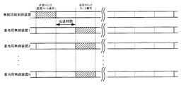
次に、図8を参照して、複数の基地局無線装置70が同じタイミングで下り送信を開始する処理を説明する。
図8には、上から順に、無線回線制御装置60における送信タイミング基底フレーム番号の例、基地局無線装置70(#1)における送信タイミングフレーム番号の例、基地局無線装置70(#2)における送信タイミングフレーム番号の例、・・・、基地局無線装置70(#N)における送信タイミングフレーム番号の例を示してある。
図8の例では、無線回線制御装置60が、下り送信を行う対象となる複数の基地局無線装置70(#1)〜(#N)との間の伝送時間の最大値分の間隔を置いて送信タイミングフレーム番号を設定し、基地局無線装置70(#1)〜(#N)に対して通知している。
Next, a process in which a plurality of base
In FIG. 8, in order from the top, an example of a transmission timing base frame number in the
In the example of FIG. 8, the
つまり、無線回線制御装置60から最も遠い基地局無線装置70の伝送時間に合わせて送信タイミングフレーム番号を設定しており、無線回線制御装置60から最も遠い基地局無線装置70に下り送信の開始指示が到達するのを他の基地局無線装置70に待機させるようにしている。
これにより、全ての基地局無線装置70が同じタイミングで下り送信を開始できるため、同一波送信のずれによる干渉を抑制することが可能となり、不感地帯を低減することができる。
In other words, the transmission timing frame number is set in accordance with the transmission time of the base
Thereby, since all base station radio |
ここで、本例の無線通信システムでは、無線回線制御装置60及び基地局無線装置70の各々が、GPS信号を受信して処理する機能を有し、共通の手法によりフレームタイミングを生成する構成となっているため、各装置が独立してフレームタイミングを生成しながらも、正確にフレームタイミングを同期させることができる。また、秒を刻むタイミングを示す1PPS信号の周期(1秒周期)をスーパーフレームに割り当て、これを10MHzクロック信号に基づいて所定数に分割して無線フレームを形成し、1PPS信号の周期でリセットされるフレーム番号を付与していくので、各フレームタイミングのフレーム位置(フレーム番号)を各装置で容易に一致させることができる。しかも、本例では、これらの処理をハードウェアで行うので、ソフトウェアで行う場合のCPU負荷やメモリ不足等に起因する処理遅延が生じることが無く、無線回線制御装置60及び基地局無線装置70の各装置間での正確なタイミング同期を実現することができる。
Here, in the radio communication system of this example, each of the
なお、上記の説明では、無線回線制御装置60から最も遠い基地局無線装置70の伝送時間に合わせて送信タイミングフレーム番号を設定したが、例えば伝送時間に閾値を設けておき、伝送時間が閾値以上となる基地局無線装置70が存在する場合には、これを除外して送信する基地局無線装置70に応じて送信タイミングフレーム番号を変更し、変更された送信タイミングフレーム番号に基づいて下り送信の開始指示を行うようにしてもよい。
すなわち、無線回線制御装置60は、伝送時間が閾値以上の基地局無線装置70が存在する場合に、当該基地局無線装置70を除外して、送信する基地局無線装置70に応じて送信タイミングフレーム番号を変更し、変更された送信タイミングフレーム番号に基づいて同じ開始タイミングが設定された下り送信の開始指示を送信する。
In the above description, the transmission timing frame number is set in accordance with the transmission time of the base
That is, when there is a base
このような構成によれば、無線回線制御装置60から遠すぎる基地局無線装置70の存在によって、基地局無線装置70に対する下り送信の開始指示の伝達が本来の予定より遅れてしまうことを防止できる。このため、例えば、基地局無線装置70から移動局無線装置90への音声データの下り送信が本来の予定より遅れて開始され、移動局無線装置90で音声出力が頭切れしてしまう、といった事態が発生することを防止できる。
なお、伝送時間が閾値以上の基地局無線装置70については、次のスーパーフレームで当該基地局無線装置70に割り当てられる無線フレームで下り送信を開始できるように送信タイミングフレーム番号を設定し、通知すればよい。
According to such a configuration, it is possible to prevent the transmission of the downlink transmission start instruction to the base
For the base
次に、拡張例として、基地局無線装置70が下り送信の対象となるデータを受信してから下り送信の開始指示を受信するまでの経過時間に上限を設ける構成について説明する。
すなわち、基地局無線装置70が、下り送信の対象となるデータを受信してからの経過時間を計時する送信開始保護タイマを備え、下り送信の開始指示を受信しないまま送信開始保護タイマがタイムアウトした場合(経過時間の上限値を上回った場合)に、下り送信を開始する。
ここで、経過時間の上限値は、それぞれの基地局無線装置70で同じであってもよく、異なっていてもよい。ただし、経過時間の上限値は、無線回線制御装置60が送信タイミングフレーム番号を決定する際に考慮している伝送時間よりも長い必要がある。
Next, as an extended example, a configuration will be described in which an upper limit is set for the elapsed time from when the base
That is, the base
Here, the upper limit value of the elapsed time may be the same in each base
通常は、図9(a)に示すように、送信開始保護タイマがタイムアウトするまでに下り送信の開始指示を受信できるので、下り送信の開始指示を受信したことに応じて移動局無線装置90への下り送信を開始する。
これに対し、無線回線制御装置60におけるGPSモジュール63の故障等でフレーム生成ができない場合や、基地局無線装置70において無線回線制御装置60からの送信タイミングフレーム番号を取り逃した場合には、移動局無線装置90への下り送信を開始できない。そこで、図9(b)に示すように、送信開始保護タイマがタイムアウトするまでに下り送信の開始指示を受信できない場合には、送信開始保護タイマのタイムアウト後に速やかに移動局無線装置90への下り送信を開始する。
Normally, as shown in FIG. 9 (a), since a downlink transmission start instruction can be received before the transmission start protection timer times out, the mobile
On the other hand, if a frame cannot be generated due to a failure of the
図10には、基地局無線装置70に送信開始保護タイマを設ける構成における動作シーケンスの例を示してある。
指令台40は、ユーザから下り送信の指示を受け付けた場合に、無線回線制御装置60へ下り送信の開始指示を送信する(処理T21)。
無線回線制御装置60は、指令台40から下り送信の開始指示を受信すると、送信タイミング基底フレーム番号を基準に送信タイミングフレーム番号を決定して下り送信の開始指示に付与し(処理T22)、送信開始電文として基地局無線装置70に送信する(処理T23)。
FIG. 10 shows an example of an operation sequence in a configuration in which the base
When receiving a downlink transmission instruction from the user, the
When receiving the downlink transmission start instruction from the
基地局無線装置70は、下り送信の対象となるデータを受信したことに応じて送信開始保護タイマを起動し(処理T24)、送信開始電文を受信して送信タイミングフレーム番号を取得できたか否かの判定を繰り返す(処理T25)。
そして、送信開始保護タイマがタイムアウトするまでに送信タイミングフレーム番号を取得できた場合には、当該取得した送信タイミングフレーム番号に該当する無線フレームから下り送信を開始する(処理T27)。一方、送信タイミングフレーム番号を取得することなく送信開始保護タイマがタイムアウトした場合(処理T26)には、その直後の無線フレームから下り送信を開始する(処理T27)。
The base
If the transmission timing frame number can be acquired before the transmission start protection timer times out, downlink transmission is started from the radio frame corresponding to the acquired transmission timing frame number (process T27). On the other hand, when the transmission start protection timer times out without acquiring the transmission timing frame number (process T26), downlink transmission is started from the radio frame immediately after that (process T27).
このような構成により、基地局は、無線回線制御装置60からの下り送信の開始指示を受信できない場合でも、送信開始保護タイマのタイムアウトによって自動的に下り送信を開始することになる。このため、無線回線制御装置60におけるGPSモジュール63の故障等でフレーム生成ができない場合や、基地局無線装置70において無線回線制御装置60からの送信タイミングフレーム番号を取り逃した場合でも、下り送信が開始されたまま放置される等の事態が発生することを回避できる。
With such a configuration, even when the base station cannot receive a downlink transmission start instruction from the
ここで、これまでの説明では、1秒周期のスーパーフレームを25個に分割して40ms周期の無線フレームを形成しているが、各フレームのフレーム長はこれに限らず任意であり、無線通信システムの用途等に応じて適宜に設定すればよい。
また、本例の無線通信システムでは、1つの無線フレームの長さを40msとしているが、これは狭帯域デジタル通信方式を規定している「ARIB STD T−61」に従ったものである。40msの無線フレームの生成は、1/n秒間隔のパルスを用いる場合にはn=25とすると制御しやすいが、必ずしもn=25でなくともよい。
Here, in the description so far, a superframe having a period of one second is divided into 25 to form a radio frame having a period of 40 ms. However, the frame length of each frame is not limited to this, and wireless communication is not limited. What is necessary is just to set suitably according to the use etc. of a system.
Further, in the wireless communication system of this example, the length of one wireless frame is 40 ms, which conforms to “ARIB STD T-61” that defines a narrowband digital communication system. Generation of a radio frame of 40 ms is easy to control when n = 25 when using pulses of 1 / n second intervals, but not necessarily n = 25.
次に、本発明を適用した無線通信システムによるシミュレーション結果について、本発明を適用しない場合と比較して説明する。
図11には、公共業務用の狭帯域SCPC(Single Channel Per Carrier)無線システムにおいて、同一周波数を用いて非同期で同時送信する場合の干渉の様子を示してある。同図では、基地局無線装置70(#1)のサービスエリアA1と、基地局無線装置70(#2)のサービスエリアA2との重なり部分に移動局無線装置90が存在する場合を想定している。
Next, a simulation result by the wireless communication system to which the present invention is applied will be described in comparison with a case where the present invention is not applied.
FIG. 11 shows the state of interference in the case of simultaneous transmission asynchronously using the same frequency in a narrowband SCPC (Single Channel Per Carrier) wireless system for public service. In the figure, it is assumed that the mobile
なお、各基地局無線装置70は、非同期のアプローチ回線により無線回線制御装置60と接続されている。このアプローチ回線は、回線品質を確保するために、通信事業者の有線回線や自営の光回線、マイクロ波多重無線装置などを用いて構成される。
Each base
ここで、公共業務用の狭帯域SCPC無線システムでは、サービスエリアの重なり部分で異なる基地局から同時に送信される無線を希望波(Desired)と妨害波(Undesired)とみなすと、希望波と妨害波の比(DU比)が21dB以上であることが「電波法関係審査基準別紙2 目的別審査基準 第2 公共業務用無線局」で定められている。なお、21dBの内容は、妨害波の情報がランダム雑音としたときの音声符号化の限界性能であるBER(Bit Error Rate;符号誤り率)=3%におけるフェージング環境下での理論所要CIR(Carrier to Interference Rate;搬送波対干渉波比)=15dBに、固定劣化マージンの6dBを加味したものである。
Here, in a narrowband SCPC radio system for public service, if radio waves transmitted simultaneously from different base stations in an overlapping area of service areas are regarded as a desired wave (Desired) and an interference wave (Undesired), the desired wave and the interference wave It is stipulated in “Radio Law-related
図11には、移動局無線装置90の位置を基準にして、DU比<21dBとなるエリアA3と、DU比<10dBとなるエリアA4を示してある。DU比<21dBの環境下では音声を正しく再生できない可能性があり、特に、DU比<10dBではフェージング環境下では音声を再生できない可能性が高い。
公共業務用のSCPC無線システムにおいては、一般的に音声が正しく再生できない場合は無音としており、現象としては、音声の途切れまたは無音の連続が発生する。
フェージングが無い場合でも、DU比の限界は概ね10dB程度であり、複数の基地局からの距離が同程度の場合にはDU比を確保できないため、受信レベルが十分であっても無線としては利用できない。
FIG. 11 shows an area A3 where the DU ratio <21 dB and an area A4 where the DU ratio <10 dB with respect to the position of the mobile
In the SCPC wireless system for public business, generally, when sound cannot be reproduced correctly, the sound is silent. As a phenomenon, the sound is interrupted or the sound is continuously silenced.
Even if there is no fading, the limit of the DU ratio is about 10 dB, and if the distance from a plurality of base stations is about the same, the DU ratio cannot be secured. Can not.
図12には、3つの基地局が非同期で同時送信した場合のシミュレーションで得られたBERの分布例を、(a)単一受信、(b)ダイバーシチ受信のそれぞれについて示してある。また、図12では、各々の基地局の位置を△印で示してある。
なお、シミュレーションは、以下の条件で行っている。
[基地局配置] 3基地局、10km間隔
[基地局アンテナ高] 15m
[端末局アンテナ高] 3m
[周波数] 270MHz
[伝搬損失モデル] Hata、中小都市モデル
[伝搬モデル] レイリーフェージング
各基地局からのパスには遅延広がりが無いものとする
[最大ドプラ周波数] 15Hz 60km/h(@270MHz)相当
[端末局雑音指数] 8dB
[外部雑音(都市雑音)] なし
[実行放射電力] 5W
[送信/受信アンテナ利得] 0dBi
FIG. 12 shows an example of BER distribution obtained by simulation when three base stations simultaneously transmit asynchronously for (a) single reception and (b) diversity reception. In FIG. 12, the position of each base station is indicated by Δ.
The simulation is performed under the following conditions.
[Base station arrangement] 3 base stations, 10 km interval [Base station antenna height] 15 m
[Terminal station antenna height] 3m
[Frequency] 270 MHz
[Propagation loss model] Hata, small and medium city model [Propagation model] Rayleigh fading
It is assumed that there is no delay spread in the path from each base station. [Maximum Doppler frequency] 15Hz 60km / h (@ 270MHz) equivalent [Terminal station noise figure] 8dB
[External noise (urban noise)] None [Effective radiation power] 5W
[Transmission / Reception Antenna Gain] 0dBi
公共業務用の狭帯域SCPC無線システムで利用可能なBERは、概ね10-2.5以下である。
各基地局が非同期送信した場合の単一受信では、図12(a)に示されるように、BERは基地局の近辺を除いて10-2.5以上となっており、広い範囲で受信に利用できない。
また、各基地局が非同期送信した場合のダイバーシチ受信では、図12(b)に示されるように、単一受信の場合よりもBERが若干良化しているものの、受信に利用できないエリアが大半である。
また、単一受信およびダイバーシチ受信のいずれにおいても、各基地局の間の中間的なエリアは受信に全く利用できない。
このように、各基地局から非同期送信を行う場合には、各基地局を中心とした個別のエリアでは受信に利用できるが、各基地局の間の中間的なエリアを含む広い範囲で受信に利用できないことが分かる。
The BER that can be used in a narrowband SCPC radio system for public service is approximately 10 -2.5 or less.
In the single reception when each base station performs asynchronous transmission, as shown in FIG. 12A, the BER is 10 −2.5 or more except in the vicinity of the base station, and cannot be used for reception in a wide range. .
Also, in diversity reception when each base station transmits asynchronously, as shown in FIG. 12B, although the BER is slightly better than in the case of single reception, most of the areas cannot be used for reception. is there.
Further, in both single reception and diversity reception, an intermediate area between base stations cannot be used for reception at all.
Thus, when performing asynchronous transmission from each base station, it can be used for reception in an individual area centered on each base station, but it can be used for reception in a wide range including an intermediate area between each base station. You can see that it is not available.
図13には、3つの基地局が同期送信した場合のシミュレーションで得られたBERの分布例を、(a)単一受信、(b)ダイバーシチ受信のそれぞれについて示してある。また、図13では、各々の基地局の位置を△印で示してある。
なお、シミュレーションは、非同期送信した場合と同じ条件で行っている。
FIG. 13 shows distribution examples of BER obtained by simulation when three base stations perform synchronous transmission for (a) single reception and (b) diversity reception, respectively. Further, in FIG. 13, the positions of the respective base stations are indicated by Δ.
The simulation is performed under the same conditions as in the case of asynchronous transmission.
各基地局が同期送信した場合の単一受信では、図13(a)に示されるように、非同期送信した場合の単一受信(図12(a))と比べて、BERが10-2.5以下となるエリアが非常に広範囲に拡大している。
また、各基地局が同期送信した場合のダイバーシチ受信でも、図13(b)に示されるように、非同期送信した場合のダイバーシチ受信(図12(b))と比べて、BERが10-2.5以下のエリアが非常に広範囲に拡大している。
また、単一受信およびダイバーシチ受信のいずれにおいても、非同期送信では受信に全く利用できなかった各基地局の間の中間的なエリアが、同期送信により受信に利用できるようになっている。
このように、非同期送信の場合には全く受信に利用できなかったエリアが、各基地局が同期送信することにより無線の干渉が低減され、良好に受信可能になることが分かる。
In the single reception when each base station transmits synchronously, as shown in FIG. 13A, the BER is 10 −2.5 or less compared to the single reception when asynchronous transmission is performed (FIG. 12A). The area to be expanded is very wide.
Further, even in diversity reception when each base station transmits synchronously, as shown in FIG. 13B, BER is 10 −2.5 or less compared to diversity reception when asynchronous transmission is performed (FIG. 12B). The area has expanded very extensively.
In both single reception and diversity reception, an intermediate area between base stations that could not be used for reception by asynchronous transmission can be used for reception by synchronous transmission.
As described above, it can be seen that, in the case of asynchronous transmission, radio interference is reduced and reception can be performed satisfactorily by transmitting each base station synchronously in an area that could not be used for reception at all.
以上、本発明に関して実施形態を基に説明したが、本発明に係るシステムや装置などの構成としては、必ずしも以上に示したものに限られず、種々の構成が用いられてもよい。また、本発明は、例えば、本発明に係る処理を実行する方法や方式、このような方法や方式を実現するためのプログラム、このようなプログラムを記憶した記憶媒体、などの形式で提供することも可能である。 As described above, the present invention has been described based on the embodiments. However, the configuration of the system and apparatus according to the present invention is not necessarily limited to the above-described configuration, and various configurations may be used. In addition, the present invention is provided in the form of, for example, a method or method for executing the processing according to the present invention, a program for realizing such a method or method, or a storage medium storing such a program. Is also possible.
本発明は、同一周波数を用いて下り送信を行う複数の基地局無線装置と、前記複数の基地局無線装置を制御する無線回線制御装置と、を有する種々の形式の無線通信システムに適用することができる。 The present invention is applied to various types of radio communication systems having a plurality of base station radio apparatuses that perform downlink transmission using the same frequency and a radio network controller that controls the plurality of base station radio apparatuses. Can do.
10:無線統制台、 20:通信卓、 30:管理監視制御卓、 40:指令台、 50:指令制御装置、 60:無線回線制御装置、 70:基地局無線装置、 90:移動局無線装置、
61:GPSアンテナ、 62:フレーム生成部、 63:GPSモジュール、 64:PLL、 65:スーパーフレームカウンタ、 66:制御部、 67:CPU、 68:基地局インタフェース部、
71:GPSアンテナ、 72:フレーム生成部、 73:GPSモジュール、 74:PLL、 75:スーパーフレームカウンタ、 76:制御部、 77:CPU、 78:無線部、 80:空中線共用器、 81:無線アンテナ
10: Radio control table, 20: Communication console, 30: Management monitoring control console, 40: Command console, 50: Command control device, 60: Radio channel control device, 70: Base station radio device, 90: Mobile station radio device,
61: GPS antenna 62: Frame generation unit 63: GPS module 64: PLL 65: Super frame counter 66: Control unit 67: CPU 68: Base station interface unit
71: GPS antenna, 72: Frame generation unit, 73: GPS module, 74: PLL, 75: Super frame counter, 76: Control unit, 77: CPU, 78: Radio unit, 80: Duplexer, 81: Radio antenna
Claims (4)
前記無線回線制御装置及び前記複数の基地局無線装置は、GPSモジュールを備えており、当該GPSモジュールからの基準信号に基づいて互いに同期したフレームタイミングで互いに同一のフレーム番号を設定した無線フレームを生成し、
前記無線回線制御装置は、前記複数の基地局無線装置に対して下り送信を同じタイミングで開始させる指示を送信するにあたり、当該指示における下り送信の開始タイミングのフレーム番号として、当該指示の送信タイミングに対して当該無線回線制御装置と前記複数の基地局無線装置との間の伝送時間の最大値分の間隔を少なくとも置いたタイミングのフレーム番号を指定し、
前記複数の基地局無線装置は、前記無線回線制御装置が指定したフレーム番号のタイミングで下り送信を開始する、
ことを特徴とする無線通信システム。 In a radio communication system having a plurality of base station radio devices that perform downlink transmission using the same frequency, and a radio network controller that controls the plurality of base station radio devices,
The radio network controller and the plurality of base station radio devices each include a GPS module, and generate radio frames in which the same frame number is set at a synchronized frame timing based on a reference signal from the GPS module. And
When transmitting an instruction to start downlink transmission at the same timing to the plurality of base station radio apparatuses, the radio network controller uses the transmission timing of the instruction as the frame number of the downlink transmission start timing in the instruction. Specify the frame number of the timing with at least an interval corresponding to the maximum value of the transmission time between the radio network controller and the plurality of base station radio devices ,
The plurality of base station radio devices start downlink transmission at a frame number specified by the radio network controller ;
A wireless communication system.
ことを特徴とする請求項1に記載の無線通信システム。 The radio network controller according to a base station radio apparatus having a transmission time within the predetermined value when a base station radio apparatus having a transmission time equal to or greater than a predetermined value exists in the plurality of base station radio apparatuses. change the frame number to start downlink transmission, it transmits the instruction frame number after the change specified in the start timing of the downlink transmission,
The wireless communication system according to claim 1.
ことを特徴とする請求項1又は請求項2に記載の無線通信システム。 The plurality of base station radio devices start downlink transmission without waiting for the instruction when a predetermined time has elapsed after receiving data targeted for downlink transmission,
The wireless communication system according to claim 1, wherein the wireless communication system is a wireless communication system.
前記無線回線制御装置及び前記複数の基地局無線装置は、前記1PPS信号の周期のスーパーフレームを整数値で分割した無線フレームを形成し、前記無線フレームのフレーム番号を、前記1PPS信号のタイミングでリセットする、
ことを特徴とする請求項1乃至請求項3のいずれかに記載の無線通信システム。 The reference signal from the GPS module is a 1PPS signal,
The radio network controller and the plurality of base station radio devices form a radio frame obtained by dividing a superframe having a period of the 1PPS signal by an integer value, and reset the frame number of the radio frame at the timing of the 1PPS signal To
The wireless communication system according to claim 1, wherein the wireless communication system is a wireless communication system.
Priority Applications (1)
| Application Number | Priority Date | Filing Date | Title |
|---|---|---|---|
| JP2014065856A JP6494918B2 (en) | 2013-12-27 | 2014-03-27 | Wireless communication system |
Applications Claiming Priority (3)
| Application Number | Priority Date | Filing Date | Title |
|---|---|---|---|
| JP2013271004 | 2013-12-27 | ||
| JP2013271004 | 2013-12-27 | ||
| JP2014065856A JP6494918B2 (en) | 2013-12-27 | 2014-03-27 | Wireless communication system |
Publications (3)
| Publication Number | Publication Date |
|---|---|
| JP2015144408A JP2015144408A (en) | 2015-08-06 |
| JP2015144408A5 JP2015144408A5 (en) | 2017-04-13 |
| JP6494918B2 true JP6494918B2 (en) | 2019-04-03 |
Family
ID=53889183
Family Applications (1)
| Application Number | Title | Priority Date | Filing Date |
|---|---|---|---|
| JP2014065856A Active JP6494918B2 (en) | 2013-12-27 | 2014-03-27 | Wireless communication system |
Country Status (1)
| Country | Link |
|---|---|
| JP (1) | JP6494918B2 (en) |
Families Citing this family (5)
| Publication number | Priority date | Publication date | Assignee | Title |
|---|---|---|---|---|
| JP6763735B2 (en) * | 2016-09-30 | 2020-09-30 | 株式会社日立国際電気 | Digital wireless system |
| JP6959580B2 (en) * | 2017-09-25 | 2021-11-02 | 株式会社Jvcケンウッド | Wireless communication system, simulcast controller, relay station and communication method |
| JP7332159B2 (en) * | 2018-11-21 | 2023-08-23 | Necプラットフォームズ株式会社 | Firefighting Command System, Firefighting Digital Radio Line Controller and Firefighting Command Transmission Program |
| WO2020105703A1 (en) * | 2018-11-21 | 2020-05-28 | Necプラットフォームズ株式会社 | Firefighting command system, firefighting command control device, firefighting digital wireless line control device, and non-transitory computer-readable medium |
| JP7461904B2 (en) | 2021-03-15 | 2024-04-04 | 株式会社日立国際電気 | Wireless communication system |
Family Cites Families (7)
| Publication number | Priority date | Publication date | Assignee | Title |
|---|---|---|---|---|
| JPH05308334A (en) * | 1992-04-28 | 1993-11-19 | Kokusai Electric Co Ltd | Frame synchronization system of tdma system radio base station |
| JP2004120586A (en) * | 2002-09-27 | 2004-04-15 | Matsushita Electric Ind Co Ltd | Communication terminal, control station and abnormal base station detection method |
| CN101132222B (en) * | 2006-08-22 | 2011-02-16 | 上海贝尔阿尔卡特股份有限公司 | Gateway equipment, communication network and synchronization method |
| JP2009038444A (en) * | 2007-07-31 | 2009-02-19 | Hitachi Kokusai Electric Inc | Network system, control method, and gateway apparatus |
| JP5173541B2 (en) * | 2008-04-04 | 2013-04-03 | ソフトバンクテレコム株式会社 | Content data transmission system |
| CN101860803A (en) * | 2010-06-12 | 2010-10-13 | 珠海无线蜂网科技有限公司 | Broadcast/television signal transmission method, transmission center, base station and system |
| JP5481685B2 (en) * | 2011-02-08 | 2014-04-23 | 株式会社日立製作所 | Time synchronization method and computer system |
-
2014
- 2014-03-27 JP JP2014065856A patent/JP6494918B2/en active Active
Also Published As
| Publication number | Publication date |
|---|---|
| JP2015144408A (en) | 2015-08-06 |
Similar Documents
| Publication | Publication Date | Title |
|---|---|---|
| JP6494918B2 (en) | Wireless communication system | |
| JP5301732B2 (en) | Air interface synchronization method, apparatus and system | |
| JP5052377B2 (en) | Radio communication base station apparatus, radio communication terminal apparatus, and gap generation method | |
| US6424637B1 (en) | Method for synchronizing a mobile station to UMTS while operating in GSM dedicated mode | |
| KR101377731B1 (en) | Methods and systems for synchronizing overlapping wireless systems | |
| JP5745055B2 (en) | Scheduling method and apparatus | |
| WO2013020458A1 (en) | Transmission scheduling method and device | |
| US20080080406A1 (en) | Method and device for increasing capacity of tdd wireless communication systems | |
| JP2016530812A (en) | Avoiding transmission pauses during network listening for small cell base stations | |
| TW200814816A (en) | Wireless communication methods and apparatus supporting multiple modes | |
| JP2016535488A (en) | System and method for setting cyclic prefix length | |
| CN110381602A (en) | Method, the network equipment and the user equipment of random access | |
| US5987338A (en) | Remote wireless unit having reduced power operating mode | |
| WO2020196534A1 (en) | Transmission device, reception device, transmission method, and reception method | |
| CN102780998A (en) | Method and device for maintaining cell synchronization | |
| JP2011151657A (en) | Radio communication apparatus, program, and communication system | |
| WO2014052204A1 (en) | Wireless communication with multiple access points | |
| WO2022056854A1 (en) | Wireless communication method and device | |
| JP2011146988A (en) | Radio communication system, base station device, terminal device and communication method | |
| CN107431960A (en) | Method, mobile communications network, base station entity, program and the computer program product synchronous for the radio net of the mobile communications network with the local clock functive that local timing reference is provided for each base station entity | |
| US11792853B2 (en) | Bidirectional scheduling in low-power wide-area networks | |
| WO2022073504A1 (en) | Data transmission method and apparatus | |
| JP6950724B2 (en) | Terminal equipment, base station equipment, wireless communication systems and wireless communication methods | |
| CN110392435A (en) | A kind of data transmission method and system | |
| CN107787012B (en) | Interference processing method and base station |
Legal Events
| Date | Code | Title | Description |
|---|---|---|---|
| A521 | Request for written amendment filed |
Free format text: JAPANESE INTERMEDIATE CODE: A523 Effective date: 20170309 |
|
| A621 | Written request for application examination |
Free format text: JAPANESE INTERMEDIATE CODE: A621 Effective date: 20170309 |
|
| A131 | Notification of reasons for refusal |
Free format text: JAPANESE INTERMEDIATE CODE: A131 Effective date: 20171121 |
|
| A977 | Report on retrieval |
Free format text: JAPANESE INTERMEDIATE CODE: A971007 Effective date: 20171122 |
|
| A521 | Request for written amendment filed |
Free format text: JAPANESE INTERMEDIATE CODE: A523 Effective date: 20180119 |
|
| A131 | Notification of reasons for refusal |
Free format text: JAPANESE INTERMEDIATE CODE: A131 Effective date: 20180724 |
|
| A521 | Request for written amendment filed |
Free format text: JAPANESE INTERMEDIATE CODE: A523 Effective date: 20180921 |
|
| TRDD | Decision of grant or rejection written | ||
| A01 | Written decision to grant a patent or to grant a registration (utility model) |
Free format text: JAPANESE INTERMEDIATE CODE: A01 Effective date: 20190212 |
|
| A61 | First payment of annual fees (during grant procedure) |
Free format text: JAPANESE INTERMEDIATE CODE: A61 Effective date: 20190306 |
|
| R150 | Certificate of patent or registration of utility model |
Ref document number: 6494918 Country of ref document: JP Free format text: JAPANESE INTERMEDIATE CODE: R150 |
|
| R250 | Receipt of annual fees |
Free format text: JAPANESE INTERMEDIATE CODE: R250 |
|
| R250 | Receipt of annual fees |
Free format text: JAPANESE INTERMEDIATE CODE: R250 |
|
| R250 | Receipt of annual fees |
Free format text: JAPANESE INTERMEDIATE CODE: R250 |