JP6494239B2 - Control device, control method, and program - Google Patents
Control device, control method, and program Download PDFInfo
- Publication number
- JP6494239B2 JP6494239B2 JP2014218725A JP2014218725A JP6494239B2 JP 6494239 B2 JP6494239 B2 JP 6494239B2 JP 2014218725 A JP2014218725 A JP 2014218725A JP 2014218725 A JP2014218725 A JP 2014218725A JP 6494239 B2 JP6494239 B2 JP 6494239B2
- Authority
- JP
- Japan
- Prior art keywords
- projection
- image
- unit
- screen
- projector
- Prior art date
- Legal status (The legal status is an assumption and is not a legal conclusion. Google has not performed a legal analysis and makes no representation as to the accuracy of the status listed.)
- Active
Links
Images


Classifications
-
- G—PHYSICS
- G03—PHOTOGRAPHY; CINEMATOGRAPHY; ANALOGOUS TECHNIQUES USING WAVES OTHER THAN OPTICAL WAVES; ELECTROGRAPHY; HOLOGRAPHY
- G03B—APPARATUS OR ARRANGEMENTS FOR TAKING PHOTOGRAPHS OR FOR PROJECTING OR VIEWING THEM; APPARATUS OR ARRANGEMENTS EMPLOYING ANALOGOUS TECHNIQUES USING WAVES OTHER THAN OPTICAL WAVES; ACCESSORIES THEREFOR
- G03B21/00—Projectors or projection-type viewers; Accessories therefor
- G03B21/14—Details
- G03B21/26—Projecting separately subsidiary matter simultaneously with main image
-
- G—PHYSICS
- G03—PHOTOGRAPHY; CINEMATOGRAPHY; ANALOGOUS TECHNIQUES USING WAVES OTHER THAN OPTICAL WAVES; ELECTROGRAPHY; HOLOGRAPHY
- G03B—APPARATUS OR ARRANGEMENTS FOR TAKING PHOTOGRAPHS OR FOR PROJECTING OR VIEWING THEM; APPARATUS OR ARRANGEMENTS EMPLOYING ANALOGOUS TECHNIQUES USING WAVES OTHER THAN OPTICAL WAVES; ACCESSORIES THEREFOR
- G03B21/00—Projectors or projection-type viewers; Accessories therefor
- G03B21/14—Details
- G03B21/142—Adjusting of projection optics
-
- G—PHYSICS
- G03—PHOTOGRAPHY; CINEMATOGRAPHY; ANALOGOUS TECHNIQUES USING WAVES OTHER THAN OPTICAL WAVES; ELECTROGRAPHY; HOLOGRAPHY
- G03B—APPARATUS OR ARRANGEMENTS FOR TAKING PHOTOGRAPHS OR FOR PROJECTING OR VIEWING THEM; APPARATUS OR ARRANGEMENTS EMPLOYING ANALOGOUS TECHNIQUES USING WAVES OTHER THAN OPTICAL WAVES; ACCESSORIES THEREFOR
- G03B21/00—Projectors or projection-type viewers; Accessories therefor
- G03B21/14—Details
- G03B21/147—Optical correction of image distortions, e.g. keystone
-
- H—ELECTRICITY
- H04—ELECTRIC COMMUNICATION TECHNIQUE
- H04N—PICTORIAL COMMUNICATION, e.g. TELEVISION
- H04N9/00—Details of colour television systems
- H04N9/12—Picture reproducers
- H04N9/31—Projection devices for colour picture display, e.g. using electronic spatial light modulators [ESLM]
- H04N9/3141—Constructional details thereof
- H04N9/3147—Multi-projection systems
-
- H—ELECTRICITY
- H04—ELECTRIC COMMUNICATION TECHNIQUE
- H04N—PICTORIAL COMMUNICATION, e.g. TELEVISION
- H04N9/00—Details of colour television systems
- H04N9/12—Picture reproducers
- H04N9/31—Projection devices for colour picture display, e.g. using electronic spatial light modulators [ESLM]
- H04N9/3179—Video signal processing therefor
- H04N9/3185—Geometric adjustment, e.g. keystone or convergence
-
- H—ELECTRICITY
- H04—ELECTRIC COMMUNICATION TECHNIQUE
- H04N—PICTORIAL COMMUNICATION, e.g. TELEVISION
- H04N9/00—Details of colour television systems
- H04N9/12—Picture reproducers
- H04N9/31—Projection devices for colour picture display, e.g. using electronic spatial light modulators [ESLM]
- H04N9/3191—Testing thereof
- H04N9/3194—Testing thereof including sensor feedback
Description
立体に投影画像を投影させる技術に関する。 The present invention relates to a technique for projecting a projection image onto a three-dimensional object.
従来、プロジェクタから建造物やフィギュアなどの立体物に対して画像を投影することが行われている。 Conventionally, an image is projected from a projector onto a three-dimensional object such as a building or a figure.
また従来、プロジェクタからスクリーンを撮影した撮像画像に基づいて、プロジェクタとスクリーンとの位置関係を特定し、特定した情報に基づいてプロジェクタが投影する投影画像の投影領域を決定する技術が知られている。 Conventionally, a technique is known in which a positional relationship between a projector and a screen is specified based on a captured image obtained by photographing the screen from a projector, and a projection area of a projection image projected by the projector is determined based on the specified information. .
特許文献1には、人物の顔面に装着された立体スクリーンに投影画像を投影することが開示されている。
また特許文献1には、立体スクリーンに設けられた複数の不可視光マーカーをマーカー撮影装置で撮影して、立体スクリーンの位置情報及び方向情報を取得することが開示されている。また、立体スクリーンの位置情報及び方向情報に基づいて、投影画像の大きさ及び方向が立体スクリーンに整合した状態となるように、投影画像を生成することが開示されている。
特許文献1に記載の投影システムでは、立体スクリーンのうち不可視光マーカーが配置された部分の位置及び向きを取得することができるが、立体スクリーンの立体形状についての情報を取得することができない。例えば立体スクリーンの投影面の凹凸等の情報を取得することができない。
In the projection system described in
従って、特許文献1に記載の投影システムでは、立体スクリーンの形状を考慮せずに投影画像が投影されることにより、投影画像が、ユーザが所望する態様で立体スクリーンに投影されない場合があった。
Therefore, in the projection system described in
上記課題を解決するため本発明にかかる制御装置は以下の構成を有する。すなわち、第1投影手段が画像を投影可能な第1投影面の位置に関する第1位置情報と、第2投影手段が画像を投影可能な第2投影面の位置に関する第2位置情報を取得する位置取得手段と、
前記第1位置情報に基づく前記第1投影面と前記第2位置情報に基づく前記第2投影面とが少なくとも部分的に重複する場合、前記第1位置情報と前記第2位置情報とに基づいて、前記第1及び第2投影手段のうちの前記重複領域に画像を投影するための投影手段を決定する決定手段と、前記決定手段による決定に応じて、前記第1投影手段に画像を投影させる制御手段とを有する。
In order to solve the above problems, a control device according to the present invention has the following configuration. That is, the position where the first projection unit obtains the first position information regarding the position of the first projection plane on which the image can be projected and the second position information about the position of the second projection plane on which the second projection unit can project the image. Acquisition means;
When the first projection plane based on the first position information and the second projection plane based on the second position information overlap at least partially, based on the first position information and the second position information Determining means for projecting an image onto the overlapping region of the first and second projecting means, and causing the first projecting means to project an image according to the determination by the determining means Control means.
本発明によれば、立体スクリーンの形状を考慮しつつ、ユーザが所望する態様で立体スクリーンに投影画像を投影させることができる。 According to the present invention, it is possible to project a projected image on a stereoscopic screen in a manner desired by the user while considering the shape of the stereoscopic screen.
(実施形態1)
実施形態1では、投影制御装置としてのプロジェクタ100が、立体をスクリーン(投影先)として、画像を投影する場合について説明する。本実施形態において、この立体は移動できるものとする。スクリーンとする立体は例えば、自動車や人体等とすることができる。
(Embodiment 1)
In the first embodiment, a case where the
本実施形態にかかるプロジェクタ100による投影処理を図3の例を用いて説明する。図3は直方体の立体300が位置Aから位置Bに移動する様子を示している。この立体300は、プロジェクタ100が投影画像を投影するスクリーンである。本実施形態ではプロジェクタ100が、立体300の面301に画像を投影する場合について説明する。プロジェクタ100は、立体300の移動の前後において、面301に画像が投影されるように、画像の投影位置及び形状を立体300の移動に応じて変化させる。
Projection processing by the
図3の例における投影処理について、プロジェクタ100からスクリーン方向を見た場合の投影画像の移動及び変形の様子を、図4を用いて説明する。
The projection process in the example of FIG. 3 will be described with reference to FIG. 4 in terms of the movement and deformation of the projected image when the screen direction is viewed from the
領域400は、図3の位置Aに立体300がある場合に、立体300の面301に投影される画像の投影領域を示している。
A
領域401は、図3の位置Bに立体300がある場合に、立体300の面301に投影される画像の投影領域を示している。
A
このように、プロジェクタ100の位置に対するスクリーンの位置が変化する場合に、本実施形態に係るプロジェクタ100は投影画像の形状を変形させる。このようにして、スクリーン位置の移動後も、スクリーン上の所定の投影領域に、移動前と同じ態様で投影画像を投影させることができる。
Thus, when the position of the screen with respect to the position of the
図4の例において、投影可能領域410は、プロジェクタ100が領域400の形状の画像を投影することができる範囲を示している。また投影可能領域411は、プロジェクタ100が領域401の形状の画像を投影することができる範囲を示している。
In the example of FIG. 4, the
次にプロジェクタ100の構成について、図1のブロック図を用いて説明する。
Next, the configuration of the
取得部101は、スクリーンに関する情報を取得する。スクリーンに関する情報には、移動するスクリーンの位置を示す位置情報が含まれる。この位置情報は、後述の投影部108が投影画像を投影する立体の位置を特定するための第1の位置情報である。この位置情報を用いて、後述の判定部104は、スクリーンに投影画像を投影する投影部108の位置とスクリーンの位置との位置関係を特定することができる。
The
例えばスクリーンの位置を示す位置情報は、プロジェクタ100が投影可能な投影可能範囲におけるスクリーンの位置を示す情報等とすることができる。また例えば、プロジェクタ100からスクリーンまでの距離を示す情報、又は、プロジェクタ100の投影部の光軸とスクリーンの投影面とが為す角度等とすることができる。これらの情報を組み合わせて位置情報として用いることとしてもよい。これらの情報は一例にすぎず、スクリーンの位置を示す位置情報は、上記の例に限られない。
For example, the position information indicating the position of the screen can be information indicating the position of the screen in the projectable range that the
取得部101は例えば、スクリーンを撮影するカメラなどの撮影部とすることができる。この場合、取得部101は、スクリーンを撮影した撮像画像を、スクリーンに関する情報として取得する。取得部101はカメラに限られない。例えば取得部101は、赤外線センサ等を用いて、スクリーンに関する情報を取得することとしてもよい。あるいは、スクリーンに関する情報をプロジェクタ100の外部の装置から取得することとしてもよい。このようにして、取得部101はスクリーンの位置情報を取得するための、スクリーンに関する情報を取得することができる。
The
設定部102は、プロジェクタ100が画像を投影するスクリーンを設定する。また、設定部102は、スクリーンにおける投影領域を設定する。例えば、図3の例では、立体300をスクリーンとすることを設定する。また、立体300のうち面301を画像の投影領域とすることを設定する。
The
画像を投影するスクリーンを設定することにより、スクリーンが移動した場合でもプロジェクタ100が当該スクリーンの移動を認識して、移動するスクリーン上に投影画像が投影され続けるようにすることができる。
By setting a screen for projecting an image, even when the screen moves, the
またスクリーンにおける投影領域を設定することにより、スクリーンの移動に伴ってプロジェクタ100に対する投影領域の位置が変更されても、当該投影領域にプロジェクタ100からの投影画像が投影され続けるようにすることができる。
In addition, by setting the projection area on the screen, even if the position of the projection area with respect to the
本実施形態では、後述の保持部103に形状の形状情報が保持されている複数の立体のモデルのうちいずれの立体のモデルをスクリーンとするかをユーザが選択する。設定部102はユーザが選択した立体をスクリーンとすることを設定する。またユーザは、選択した立体上の領域のうちどの領域に画像を投影するかを選択する。例えば、ユーザは、直方体形状のスクリーンに投影画像を投影するのか、円柱形状のスクリーンに投影画像を投影するのか、球体形状のスクリーンに投影画像を投影するのか等を選択して設定することができる。ただし、スクリーンの形状はこれらの例に限られない。
In the present embodiment, the user selects which solid model from among a plurality of solid models whose shape information is held in the
例えば、プロジェクタ100に接続されたモニタ等にユーザが選択した立体のモデルが表示される。ユーザはそのモデル上の領域を選択して、立体上に画像を投影するための投影領域を設定することができる。例えば、立体のモデル上で投影領域の頂点をポインタ等で指定することにより投影領域を設定することができる。あるいは、立体のいずれの面を投影領域とするかを選択することとしてもよい。立体のモデルは、モニタに表示される場合に限られず、後述の投影部108がスクリーン上に投影することとしてもよい。あるいは、取得部101が取得した撮像画像に基づいてスクリーン及びスクリーン上の投影領域を設定することとしてもよい。この撮像画像は、プロジェクタ100から、プロジェクタ100が画像を投影する方向にある被写体を撮像した撮像画像である。
For example, a three-dimensional model selected by the user is displayed on a monitor or the like connected to the
例えば、撮像画像のうちスクリーンとする被写体をユーザがポインタ等で指定することにより、スクリーンとする被写体を選択することができる。この場合、ユーザがスクリーンとして選択した被写体と、保持部103に保持されている立体の立体形状の関連付けを行う。この関連付けはユーザが行うこととしてもよい。あるいは自動的に行われることとしてもよい。あるいは、撮像画像のうち保持部103に立体の形状情報が保持されている立体を自動的に検出して、スクリーンとして設定することとしてもよい。設定部102によるスクリーンの設定方法、及び、投影領域の設定方法は特に限定しない。
For example, a subject to be a screen can be selected by a user specifying a subject to be a screen from the captured image with a pointer or the like. In this case, the subject selected by the user as the screen is associated with the three-dimensional shape held in the holding
保持部103は、スクリーンとなる立体の形状を示す形状情報を保持する。プロジェクタ100は、例えば、形状情報をPC(Personal Computer)、3Dスキャナ、3Dプリンタなどの情報処理装置から取得して保持部103に予め保持すことができる。保持部に保持される形状情報はスクリーンの全体の立体の形状とすることができる。または、投影面のみの形状情報等、スクリーンの一部の立体形状とすることとしてもよい。
The holding |
保持部103は例えば、RAM(Random Access Memory)やハードディスクとすることができる。あるいは、メモリカード等、プロジェクタ100に接続される外部記録装置が形状情報を保持してもよい。
The holding
判定部104は、取得部101が取得したスクリーンに関する情報と、保持部103に保持されたスクリーンの形状情報とに基づいて、設定部102で設定した投影領域の撮像画像における位置を特定する。
The
取得部101が取得するスクリーンに関する情報とは、例えばプロジェクタ100が画像を投影する方向にある被写体を撮影した撮像画像から得られる情報である。撮像画像から得られる情報は、スクリーンの位置情報を含む。スクリーンの位置を示す位置情報は、上述のように、プロジェクタ100が投影可能な投影可能範囲におけるスクリーンの位置を示す情報等とすることができる。また例えば、プロジェクタ100からスクリーンまでの距離を示す情報、又は、プロジェクタ100の投影部の光軸とスクリーンの投影面とが為す角度等とすることができる。
The information regarding the screen acquired by the
判定部104は、設定部102が設定した設定情報を取得する。また判定部104は、スクリーンとして設定した立体の形状情報を保持部103から取得する。判定部104は、保持部103から取得した形状情報を用いて、撮像画像中に設定されたスクリーンが映っているかを判定する。本実施形態では形状情報として3次元情報を用いているため、撮像画像にスクリーンのいずれの面が映っていても、撮像画像からスクリーンの位置及び方向を検出することができる。
The
スクリーンとして設定した立体の形状情報としての3次元情報は、立体における任意の点を原点とし、この原点と立体上に存在する各点との相対位置を表す形状情報である。例えば、スクリーンとして設定した立体が直方体である場合、6つの頂点のうちの一つを原点とした場合の、原点と他の5つの頂点との位置関係を示す情報である。また例えば、スクリーンとして設定した立体が円柱体である場合、3次元情報には、円形の底面の中心を原点とした場合の、当該底面における中心から円弧までの距離(半径)を示す情報が含まれる。また底面の中心から当該底面に対向する円形の上面の中心までの距離(円柱の高さ)を示す情報が含まれる。 The three-dimensional information as the shape information of the solid set as the screen is shape information representing the relative position between this origin and each point existing on the solid with an arbitrary point in the solid as the origin. For example, when the solid set as the screen is a rectangular parallelepiped, the information indicates the positional relationship between the origin and the other five vertices when one of the six vertices is the origin. For example, when the solid set as the screen is a cylindrical body, the three-dimensional information includes information indicating the distance (radius) from the center to the arc on the bottom surface when the center of the circular bottom surface is the origin. It is. Information indicating the distance (the height of the cylinder) from the center of the bottom surface to the center of the circular top surface facing the bottom surface is included.
判定部104は、プロジェクタ100が投影可能な投影範囲を3次元座標系で管理する。例えば判定部104は、プロジェクタの投影部の位置を原点として、投影部の光軸方向と、プロジェクタが置かれている面に対する水平方向と、鉛直方向の3つを軸とする3次元座標における、プロジェクタ100の投影範囲を管理する。
The
判定部104は、スクリーンのとして設定した立体において設定した原点の、プロジェクタの投影範囲を管理するための座標系における位置と、当該立体の3次元情報とを用いて、プロジェクタの投影範囲における該立体の位置や向きを特定する。このようにして判定部104は、上述の3次元座標系における、立体スクリーン上の各点の3次元位置を特定することができる。
The
決定部105は、取得部101が取得した位置情報、保持部103から取得した形状情報、及び、設定部が設定した設定情報に基づいて、プロジェクタ100が投影画像を投影できる領域(以下、投影可能領域)において実際に画像を投影する領域を決定する。本実施形態では、決定部105は投影可能領域において設定された座標系における座標値を決定することにより、画像の投影領域を決定する。決定部105は、投影可能領域における画像の投影領域を決定することにより、投影部108が立体に投影する投影画像の形状を決定する。また決定部105は、投影可能領域における画像の投影領域を決定することにより、投影画像の投影位置を決定する。
Based on the position information acquired by the
入力部106は、投影部108がスクリーンに投影する画像データを入力する。例えば入力部106は、PC等の情報処理装置から出力された画像データを入力する。
The
制御部107は、入力部106が入力した画像データの変形処理を行う。制御部107は、決定部105が決定した座標に基づいて画像データを変形する。例えば、入力部106が入力した画像データが、決定部105が決定した投影領域に歪みが補正された状態で投影されるよう、入力した画像データの変形処理を行う。また制御部107は、変形した画像データを後述の投影部108に出力する。このようにして制御部107は、投影部108を制御して、決定部105が決定した形状に応じた形状の画像データを立体に投影させる制御を行う。また制御部107は、投影部108を制御して、決定部105が決定した投影位置に画像データを投影させる。
The
投影部108は、制御部107で変形処理した画像をスクリーンに投影する。投影部108が投影する画像は、動画像であっても静止画であってもよい。
The
図1に示した各ブロックの機能の一部又は全体は、ハードウエアによって構成されてもよい。この場合、各ブロックを1つのハードウエアとしてもよいし、いくつかのブロックを統合したハードウエアとしてもよい。あるいは、図1に示した各ブロックの機能の一部又は全体は、記録媒体に記録されたプログラムをプロセッサが実行することにより実現されることとしてもよい。 A part or all of the functions of the blocks shown in FIG. 1 may be configured by hardware. In this case, each block may be one piece of hardware, or hardware in which several blocks are integrated. Alternatively, some or all of the functions of the blocks shown in FIG. 1 may be realized by a processor executing a program recorded on a recording medium.
プロジェクタ100がプロセッサを有する場合の構成例を図10に示す。プロセッサ1001は、ROM(Read Only Memory)1003に記録されたプログラムを読み出して実行する。プロセッサ1001は、例えばCPU(Central Processing Unit)やGPU(Graphics Processing Unit)等とすることができる。
FIG. 10 shows a configuration example when the
プロセッサ1001は、図1に示した設定部102、判定部104、決定部105、及び、制御部107の機能を実現する構成である。
The
RAM1002は、プロセッサ1001がROM1003から読み出したプログラムを展開する。RAM1002は、プロセッサ1001のワークスペースとして用いられる。
The
ROM1003は、プロセッサ1001が実行するためのプログラムを記録した記録媒体である。またROM1003は立体の形状情報を保持する。ROM1003は、図1に示した保持部103の機能を実現する構成である。
The
通信部1004は、プロジェクタ100が投影する投影画像をPC等の外部装置から取得するための通信インタフェースである。通信部1004は、図1に示した入力部106の機能を実現する構成である。
The
投影部1005は、プロセッサ1001の制御に応じて、画像データをスクリーンに投影する。投影部1005は、例えば、光源、投影する画像を表示する表示部、プリズム、ミラー、投射レンズ等を有することができる。投影部1005の構成については特に限定しない。投影部1005は、図1に示した投影部108の機能を実現する構成である。
The
撮影部1006は、スクリーンを撮影する。撮影部1006は例えばカメラユニットである。撮影部1006は、取得部101の機能を実現する構成である。
The photographing
次に、本実施形態に係るプロジェクタ100の動作について図2を用いて説明する。プロジェクタ100がプロセッサ1001、RAM1002、及び、ROM1003を内蔵する形態では、図2に示した処理は、プロセッサ1001がROM1003に格納されたプログラムを実行することにより実現される。あるいは、図2に示す処理の一部又は全体をハードウエアが行うこととしてもよい。
Next, the operation of the
ユーザによりプロジェクタ100による投影処理の開始が指示されると、まずステップS201において、設定部102は、スクリーンと当該スクリーン上の投影領域を設定する。
When the user gives an instruction to start projection processing by the
次にステップS202において、取得部101は、プロジェクタ100の投影可能範囲を含む撮像画像を取得する。図4の例では、取得部101は投影可能領域410を含む領域の撮像画像を取得する。そして取得部101は、取得した撮像画像を判定部104に出力する。本実施例では、投影画像を投影しない状態で、投影可能範囲を撮像した撮像画像を取得するものとする。
Next, in step S <b> 202, the
ステップS203において、判定部104は、取得部101が取得した撮像画像を解析する。判定部104は、スクリーン上の投影領域が、プロジェクタ100の投影可能領域に含まれているか判定する。図4の例では、移動後のスクリーンの投影領域に対応する領域401が、変形処理後の投影可能領域411に含まれるかを判定する。ステップS203の処理の詳細は、図12を用いて後述する。図4の例ではスクリーンの移動に伴って投影領域が変化する場合について説明するが、本発明はスクリーンが移動する場合以外にも適用可能である。例えば、取得部101が取得した撮像画像から特定されたスクリーンの設置位置と、保持部103が保持するスクリーンの3次元形状情報とに基づき、当該スクリーンにおけるユーザの所望の位置に所定の画像を歪みが補正された状態で投影することができる。
In step S <b> 203, the
領域401が投影可能領域411内に入っていない場合(ステップS203においてNoの場合)ステップS202に戻る。一方、領域401が投影可能領域411内に入っている場合(ステップS203においてYesの場合)、ステップS204に進む。
If the
ステップS204において、判定部104は、スクリーンの向きを判定する。判定部104は、保持部103から取得した形状情報に基づいて、スクリーンの向きを判定することができる。判定結果に基づいて判定部104は、取得部101が取得した撮像画像に映ったスクリーンの画像における、投影領域の位置を特定する。そして特定した位置を示す情報を決定部105に出力する。
In step S204, the
次にステップS205において、決定部105はプロジェクタ100の投影可能領域における、画像を投影させる領域の座標を決定し、制御部107に出力する。図4の例では、投影可能領域411における領域401の位置を示す情報を制御部107に出力する。出力される情報は、例えば、投影可能領域411上に設定された座標系における、領域401の各頂点の座標値とすることができる。
Next, in step S <b> 205, the
次にステップS206において、制御部107は、決定部105から入力した投影領域の座標情報に基づいて、入力部106から入力する画像データの変形処理を行う。そして、変形処理後の画像データを投影部108に出力して投影部108に投影させる。
In step S <b> 206, the
ステップS207において、投影部108は、制御部107から入力した画像を投影する。
In step S207, the
ステップ208において、投影部108は、投影領域の座標がプロジェクタ100の投影可能領域の端部に来ていなければステップS202に戻って一連の処理を継続し、来ていれば投影を終了する。例えば、プロジェクタ100が投影方向を変更して、プロジェクタ100が投影方向を変更可能な物理的な限界に達した場合は、プロジェクタ100からの画像の投影を終了する。
In step 208, the
次にステップS203において判定部104が行う処理の詳細について、図11のフローチャートを用いて説明する。
Next, details of the processing performed by the
判定部104は、保持部103からスクリーンの形状情報を取得する(S1101)。例えば、判定部104は、設定部102がスクリーンとして設定した物体の形状が直方体であることを示す情報を取得する。さらに、直方体の底面の縦及び横の長さ、並びに、直方体の高さを特定するための情報を取得する。本実施形態では、スクリーンとして設定された立体と、保持部103に保持されている形状情報とは、設定部102によって予め関連付けられているものとする。
The
本実施形態ではスクリーンの形状を取得する場合について説明するが、スクリーンの一部の形状のみを保持することとしてもよい。保持部103が保持する形状情報は、プロジェクタ100が投影画像を投影すべき領域の形状を示す情報であればよい。
In this embodiment, a case where the shape of the screen is acquired will be described, but only a part of the shape of the screen may be held. The shape information held by the holding
次に判定部104は、移動後のスクリーンの位置情報を取得する(S1102)。例えば判定部104は、プロジェクタ100の投影可能範囲を示す3次元座標系におけるスクリーンの位置、及び、立体スクリーンの1つの面の方向(向き)を示す情報を取得する。スクリーンの方向を示す情報は、例えば、プロジェクタ100の投影方向(光軸方向)に対して垂直な面に対する、現在のスクリーンの面の向きの相対関係を示す情報である。
Next, the
判定部104は、取得部101が取得した撮像画像から、スクリーンの移動後の位置及び方向を特定する。撮像画像におけるスクリーンの位置及び方向は、保持部103から取得した形状情報と、撮像画像に撮像されたスクリーンの形状、大きさなどの情報と比較して特定することができる。本実施形態では、スクリーンの位置及び方向の検出の方法について特に限定しない。
The
次に判定部104は、移動後のスクリーンに投影する投影画像の形状を特定する(1103)。図4に示した例では、領域401の形状を特定する。
Next, the
投影画像は、投影可能領域の中心から離れるに従って形状が歪むため、歪みを補正する処理が必要となる。この形状の歪みは例えば、プロジェクタ100の投影方向がプロジェクタ100の投影部を構成する球面レンズの光軸方向と乖離するに従い、レンズの曲面形状の影響を受けることによって生じる。判定部104は、レンズの光軸方向と投影画像と投影すべき方向との乖離の度合い(例えば、角度)を、取得部101が取得した撮像画像を用いて判定することができる。判定部104は例えば、撮像画像における、投影可能領域410の中心から、移動後のスクリーンの位置が離れている距離に基づいて、レンズの光軸方向と投影画像と投影すべき方向との乖離の度合いを判定する。そして、その度合いに基づいて、画像がどの程度歪むかを特定することができる。判定部104は、特定した歪みの度合いを用いることにより、移動後のスクリーンに投影する画像の形状を特定することができる。
Since the shape of the projected image is distorted as the distance from the center of the projectable area increases, it is necessary to correct the distortion. For example, the distortion of the shape is caused by the influence of the curved surface shape of the lens as the projection direction of the
上述のように判定部104は、上述の3次元座標系における、立体スクリーン上の各点の3次元位置を特定する。さらに判定部104は、プロジェクタ100の光軸方向に対するスクリーンの相対位置に基づいて、投影される画像の歪み量を特定することができる。これらの情報を用いて、立体スクリーン上の所望の点に、所望の画像を画素単位で配置して画像を投影することができる。
As described above, the
また判定部104は例えば、スクリーンの投影面が向いている方向と保持部103から取得した形状情報とに基づいて、移動後のスクリーンに投影する画像の形状を特定することができる。スクリーンの投影面が向いている方向は、取得部101が取得した撮像画像と、保持部103から取得した形状情報とを比較することによって特定することができる。例えば判定部104は、撮像画像に含まれているスクリーンの面が、保持部103から取得した形状情報が示す立体のどの面と対応するかを判定して、スクリーンの方向を特定することができる。
Further, for example, the
さらに判定部104は、特定した方向を向いたスクリーンに投影すべき画像の形状を、保持部103から取得した形状情報に基づいて決定する。形状情報を用いることによって、特定した方向を向いたスクリーンをプロジェクタ100から見た場合のスクリーンの形状を詳細に把握することができる。従って、スクリーンの方向のみを用いて投影画像を補正する場合に比べて、よりスクリーン形状に対応するようにして、投影すべき画像の形状を決定することができる。
Further, the
つぎに判定部104は、特定した形状の画像をプロジェクタ100が投影することができる投影可能範囲を特定する(S1104)。図4の例では、領域401の形状の画像を投影することができる範囲である投影可能領域411を特定する。
Next, the
そして判定部104は、ステップS1104において特定した投影可能領域411に、移動後のスクリーン上の投影領域が含まれるかを判定する。以上のようにして、ステップS203における判定処理を行うことができる。
Then, the
以上のように、本実施形態では、移動前のスクリーンに投影した画像を変形して移動後のスクリーンに投影する補正画像を生成するために、スクリーンの形状情報を利用する。このような構成によれば、撮像装置でスクリーンを撮像した撮像画像のみに基づいて投影画像の補正処理を行う場合に比べて、よりスクリーン形状に対応した補正画像を生成することができる。 As described above, in the present embodiment, screen shape information is used to generate a corrected image that is deformed from the image projected onto the screen before movement and projected onto the screen after movement. According to such a configuration, a corrected image corresponding to the screen shape can be generated more than in the case where the projection image correction process is performed based only on the captured image obtained by capturing the screen with the imaging device.
本実施形態では、投影する画像の形状を補正する場合について説明したが、形状のみならず、入力された画像データのうち、いずれの部分を投影するかを、スクリーンの向き及び形状用法に基づいて決定することとしてもよい。例えば、スクリーン上の画像を投影すべき領域のうち、プロジェクタ100から画像を投影できない方向を向いている領域に対応する部分の画像は、プロジェクタ100から画像を投影しないようにしてもよい。
In this embodiment, the case of correcting the shape of the image to be projected has been described. However, not only the shape but also which part of the input image data is to be projected is based on the screen orientation and shape usage. It may be determined. For example, an image of a portion corresponding to a region facing a direction in which an image cannot be projected from the
なお、本実施例ではプロジェクタを1台のみ用いて画像の投影を行う場合について説明したが、これに限らず、複数台のプロジェクタを用いて画像を投影する投影システムに適用することも可能である。 In this embodiment, the case of projecting an image using only one projector has been described. However, the present invention is not limited to this, and the present invention can be applied to a projection system that projects an image using a plurality of projectors. .
図5は2台のプロジェクタを使って投影対象である動体の動きに追従して動体の2つの投影領域に画像を投影する様子を示した図である。 FIG. 5 is a diagram showing a state in which an image is projected onto two projection areas of a moving object following the movement of the moving object that is a projection target using two projectors.
図5の例ではプロジェクタ150、及び、プロジェクタ151を用いて、1つのスクリーン350に画像を投影する。図5の例では、スクリーン350上の領域351及び領域352に投影画像を投影する。
In the example of FIG. 5, an image is projected onto one
図5の例のように、スクリーン350上の2つの領域351、352が同一平面上にない場合、プロジェクタと投影領域の位置関係によっては1台のプロジェクタでは全ての投影領域に投影できないことがある。このような場合にはプロジェクタ150が領域351に対して画像を投影し、プロジェクタ151が領域352に画像を投影することにより、複数の領域351及び352に画像を投影することができる。
When the two
プロジェクタ150及びプロジェクタ151は、それぞれ図2に示したフローチャートに示す手順で処理を行う。すなわち、プロジェクタ150と領域351との関係が、図3に示したプロジェクタ100と面301との関係となるように処理を行う。またプロジェクタ151と領域352との関係が、図3に示したプロジェクタ100と面301との関係となるように処理を行う。
Each of the
このようにして、立体形状を有するスクリーンの複数の面に同時に投影画像を投影する場合にも、投影面の形状に対応するようにして投影画像を投影することができる。 In this way, even when a projected image is simultaneously projected onto a plurality of screen surfaces having a three-dimensional shape, the projected image can be projected so as to correspond to the shape of the projected surface.
(実施形態2)
実施形態2では、スクリーンの投影領域が複数のプロジェクタから投影可能な場合に複数のプロジェクタが連携して投影領域を変化させる例を示す。
(Embodiment 2)
The second embodiment shows an example in which a plurality of projectors cooperate to change the projection area when the projection area of the screen can be projected from the plurality of projectors.
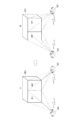
実施形態2において、複数のプロジェクタが実行する処理について、図8を用いて説明する。図8の左図は、スクリーンである立体800が位置Aに有る場合に、プロジェクタ600及びプロジェクタ650が立体800に対して画像を投影する様子を示している。また、図8の右図は、立体800が位置Aから位置Bに移動した場合に、プロジェクタ600及びプロジェクタ650が立体800に対して画像を投影する様子を示している。
Processing executed by a plurality of projectors in the second embodiment will be described with reference to FIG. The left diagram in FIG. 8 illustrates a state in which the
図8においてプロジェクタ600が画像を投影する範囲を投影領域801とする。また、プロジェクタ650が画像を投影する範囲を投影領域802とする。本実施形態において、投影領域801、802は同一平面上にあり、当該平面における投影領域の範囲は、各プロジェクタと立体800との位置関係に基づいて変化する。
In FIG. 8, a range in which the
例えば、スクリーンである立体800が位置Aから位置Bに移動するとき、投影領域801、802は図8に示すように変化する。
For example, when the solid 800 as a screen moves from position A to position B, the
実施形態2に係るプロジェクタ600が有する機能を表すブロック図を図6に示す。図6に示した構成のうち、図1と同じ構成については同じ符号を付して説明を省略する。
FIG. 6 is a block diagram illustrating functions of the
決定部605は、実施形態1において説明した決定部105と同じ機能に加え、プロジェクタ600及びプロジェクタ650の投影領域に対する相対位置を示す情報に基づいて、プロジェクタ600の投影領域を決定する。
In addition to the same function as the
特定部620は、投影領域に対するプロジェクタ600の投影方向を特定する。投影方向は、プロジェクタ600の光軸に対応する。プロジェクタ600の投影方向は、プロジェクタ600の位置とスクリーンの位置との相対位置、及び、スクリーンの向きに基づいて特定することができる。プロジェクタ600とスクリーンの相対位置、及び、スクリーンの向きは、実施形態1において図11を用いて説明した方法と同様にして特定することができる。特定部620は、スクリーンの位置を特定するための第1の位置情報に基づいて、投影部108の位置とスクリーンとの相対位置に応じた第3の位置情報を取得する。
The specifying
送受信部621は、特定部620で特定されたプロジェクタ600の投影方向を示す情報を外部装置に送信する。プロジェクタ600は、他のプロジェクタ650に投影方向を示す情報を送信する。あるいは、プロジェクタ600は、プロジェクタ600及びプロジェクタ650を制御する制御装置に、光軸の向きを示す情報を送信することとしてもよい。制御装置はプロジェクタ600から受信した情報を、他のプロジェクタ650に送信する。このようにして、光軸の向きを示す情報は、直接的又は間接的に、他のプロジェクタ650に送信される。
The transmission /
また送受信部621は、他のプロジェクタ650の投影方向を他のプロジェクタ650から直接的に、又は、上述の制御装置を介して間接的に受信する。このようにして送受信部621は、立体に投影画像を投影する第2の投影手段の位置と立体の位置との相対位置に応じた第2の位置情報を受信する。
Further, the transmission /
実施形態1と同様に、図6に示した各ブロックの機能の一部又は全体は、ハードウエアによって構成することができる。あるいは、図1に示した各ブロックの機能の一部又は全体は、記録媒体に記録されたプログラムをプロセッサが実行することにより実現されることとしてもよい。図6に示した各ブロックの機能は、図10に示した構成によって実現することとしてもよい。 Similar to the first embodiment, part or all of the functions of the blocks illustrated in FIG. 6 can be configured by hardware. Alternatively, some or all of the functions of the blocks shown in FIG. 1 may be realized by a processor executing a program recorded on a recording medium. The function of each block shown in FIG. 6 may be realized by the configuration shown in FIG.
図6に示した各機能が図10に示した構成によって実現される場合、特定部620の機能は、プロセッサ1001が、ROM1003から読み出したプログラムをRAM1002に展開して実行することにより実現することができる。また送受信部621の機能は、図10に示した通信部1004によって実現することができる。
When each function illustrated in FIG. 6 is realized by the configuration illustrated in FIG. 10, the function of the specifying
図6に示したプロジェクタ600が行う処理を、図7のフローチャートを用いて説明する。プロジェクタ100がプロセッサ1001、RAM1002、及び、ROM1003を内蔵する形態では、図7に示した処理は、プロセッサ1001がメモリ1002に格納されたプログラムを実行することにより実現される。あるいは、図2に示す処理の一部又は全体をハードウエアが行うこととしてもよい。
Processing performed by the
ステップS701からステップS704までの処理は、図2に示したフローチャートのステップS201からS204までの処理と同様であるため、ここでの説明を省略する。 Since the processing from step S701 to step S704 is the same as the processing from step S201 to S204 in the flowchart shown in FIG. 2, the description thereof is omitted here.
ステップS705において、特定部620はプロジェクタ600の投影方向を特定する。
In step S705, the specifying
次にステップS706において、送受信部621は特定部620が特定したプロジェクタ600の投影方向を示す情報を、他のプロジェクタ650に送信する。送受信部621は特定部620が特定した情報を、プロジェクタ600に接続された制御装置に対して送信し、制御装置が他のプロジェクタ650に転送することとしてもよい。
In step S <b> 706, the transmission /
また、送受信部621は周辺の他のプロジェクタ650又は制御装置から、他のプロジェクタ650の投影方向示す情報を受信する。本実施形態において送受信部621は、プロジェクタ600および650の各投影方向と投影領域801、802との相対関係を決定部605に出力する。ここで相対関係とはたとえば、光軸と投影領域とが交わる角度とすることができる。
The transmission /
次にステップS707において、決定部605は、プロジェクタ600の投影可能範囲上に設定した座標系における、プロジェクタ600の投影領域の位置を示す座標を決定する。
In step S <b> 707, the
次にステップS708において、決定部605は、プロジェクタ600および650と投影領域801および802との相対関係に基づいて、プロジェクタ600が投影する投影領域801の範囲を決定する。投影範囲801の決定方法については、図9を用いて後述する。
Next, in step S708, the
ステップS709からステップS711までの処理は、実施形態1において図2を用いて説明したステップS206からステップS208までの処理と同様であるため説明を省略する。 The processing from step S709 to step S711 is the same as the processing from step S206 to step S208 described with reference to FIG.
ここでステップS708における処理について図9及び図12を用いて説明する。決定部605は、スクリーンの位置及び向きと、プロジェクタ600の投影方向とに基づいて、立体800の投影面とプロジェクタ600の光軸との交点901の位置を特定する(S1201)。また、スクリーンの位置及び向きと、プロジェクタ650の投影方向とに基づいて、立体800の投影面とプロジェクタ650の光軸との交点902の位置を特定する(S1202)。
Here, the processing in step S708 will be described with reference to FIGS. The determining
つぎに立体800上の任意の点P(i)と交点901との距離L1を求める(S1203)。また点P(i)と交点902との距離求める(S1204)。ここで、iは1以上N以下の整数とする。
Next, a distance L1 between an arbitrary point P (i) on the solid 800 and the
つぎに決定部605はL1とL2を比較する(S1205)。L1がL2以下である場合(S1205においてYesの場合)、決定部605は点P(i)を含む領域をプロジェクタ600の投影領域と決定する(S1206)。一方L1がL2よりも大きい場合(S1205においてNoの場合)、決定部605は点P(i)を含む領域をプロジェクタ650の投影領域と決定する(S1207)。
Next, the
点P(i)を含む領域の投影を行うプロジェクタを決定した後、決定部605はiをインクリメントする(S1208)。そしてインクリメントしたiがN以下であるか判定する(S1209)。iがN以下である場合(S1209でNoの場合)にはステップS1203からS1209の処理を繰り返す。一方、インクリメントしたiがNより大きい場合(S1209でYesの場合)には、立体800の投影面の全ての点について判定を終えたと判定して処理を終了する。
After determining the projector that projects the area including the point P (i), the
このようにして、スクリーンにおける撮像画像の投影領域のうち、L1がL2よりも短い領域に、第1の投影部(投影部108)から投影画像を投影させる。L1は、第1の投影部(投影部108)の光軸と投影領域との交点からの距離である。またL2は、第2の投影部(プロジェクタ650の投影部)の光軸と投影領域との交点からの距離である。 In this manner, the projection image is projected from the first projection unit (projection unit 108) to a region where L1 is shorter than L2 among the projection regions of the captured image on the screen. L1 is the distance from the intersection of the optical axis of the first projection unit (projection unit 108) and the projection area. L2 is the distance from the intersection of the optical axis of the second projection unit (projection unit of projector 650) and the projection area.
なお、プロジェクタ650においては同様の処理を行うことにより投影領域802に対する画像処理を行い、投影領域802に変形処理された画像を投影する。プロジェクタ650は、プロジェクタ600の決定部605が図12に示した処理を実行して決定した結果をプロジェクタ600から受信してプロジェクタ650の投影範囲を決定することとしてもよい。
Note that the
以上のようにして、図8に示すように立体800の動きに従って投影領域801、802が変化し、2つのプロジェクタのうち、その光軸と投影面の交点に近い範囲を各プロジェクタが投影することになり、画像を投影領域に投影することができる。
As described above, as shown in FIG. 8, the
このようにして、立体形状を有するスクリーンに複数のプロジェクタが同時に投影画像を投影する場合にも投影面の形状に一致するようにして投影画像を投影することができる。 In this way, even when a plurality of projectors simultaneously project a projected image on a screen having a three-dimensional shape, the projected image can be projected so as to match the shape of the projection surface.
(その他の実施形態)
実施形態1及び実施形態2では、プロジェクタ100、600、及び、650が自身の投影部の投影制御を行う場合について説明したが、これに限らない。例えば、上記の投影制御を行う制御装置はプロジェクタの外部に接続された投影制御システムによっても同様の効果を奏することができる。例えばこの制御装置は、図1に示した機能ブロックのうち、取得部101、判定部104、決定部105を少なくとも有する構成とすることができる。
(Other embodiments)
In the first and second embodiments, the case where the
本発明は、上述の実施形態の1以上の機能を実現するプログラムを、ネットワーク又は記憶媒体を介してシステム又は装置に供給し、そのシステム又は装置のコンピュータにおける1つ以上のプロセッサがプログラムを読出し実行する処理でも実現可能である。また、1以上の機能を実現する回路(例えば、ASIC)によっても実現可能である。 The present invention supplies a program that realizes one or more functions of the above-described embodiments to a system or apparatus via a network or a storage medium, and one or more processors in the computer of the system or apparatus read and execute the program This process can be realized. It can also be realized by a circuit (for example, ASIC) that realizes one or more functions.
101 取得部
102 設定部
103 保持部
104 判定部
105 決定部
106 入力部
107 制御部
108 投影部
DESCRIPTION OF
Claims (11)
前記第1位置情報に基づく前記第1投影面と前記第2位置情報に基づく前記第2投影面とが少なくとも部分的に重複する場合、前記第1位置情報と前記第2位置情報とに基づいて、前記第1及び第2投影手段のうちの前記重複領域に画像を投影するための投影手段を決定する決定手段と、
前記決定手段による決定に応じて、前記第1投影手段に画像を投影させる制御手段とを有することを特徴とする制御装置。 Position acquisition means for acquiring first position information relating to the position of the first projection plane on which the first projection means can project an image, and second position information relating to the position of the second projection plane on which the second projection means can project an image. When,
When the first projection plane based on the first position information and the second projection plane based on the second position information overlap at least partially, based on the first position information and the second position information Deciding means for deciding a projection means for projecting an image onto the overlapping region of the first and second projection means ;
And a control unit that causes the first projection unit to project an image in accordance with the determination by the determination unit.
前記制御手段は、前記形状情報に基づいて、前記第1投影手段に画像を投影させることを特徴とする請求項1乃至3の何れか1項に記載に記載の制御装置。4. The control device according to claim 1, wherein the control unit causes the first projection unit to project an image based on the shape information. 5.
前記第1の投影面を有する投影対象物は移動物体であり、
前記形状取得手段は、前記移動物体としての前記投影対象物の位置に関する位置情報を取得し、
前記特定手段は、前記形状取得手段が取得した前記位置情報に基づいて、前記投影手段による画像の形状を特定し、
前記制御手段は、前記第1投影手段を制御して、前記特定手段が特定した形状に応じた画像を投影させることを特徴とする請求項4に記載の制御装置。 And a specifying unit that specifies the shape of an image projected by the first projecting unit based on the shape information.
The projection object having the first projection plane is a moving object,
The shape acquisition means acquires position information regarding the position of the projection target as the moving object,
The particular means, on the basis of the position information where the shape acquisition unit has acquired, the shape of the image to identify the by the projection means,
It said control means, said first control the projection means, the control device according to claim 4, wherein the specific means, characterized in that projecting the image in accordance with the Japanese boss was shaped.
前記制御手段は、前記第1投影手段を制御して、前記決定手段が決定した前記領域に画像データに応じた画像を投影させることを特徴とする請求項1乃至5の何れか1項に記載の制御装置。 Based on the first position information and the second position information, the determination means has a distance from an intersection of the optical axis of the first projection means and the projection area, among the projection areas of the image on the projection target. Deciding to project an image from the first projection means onto an area shorter than the distance from the intersection of the optical axis of the second projection means and the projection area;
The said control means controls the said 1st projection means, The image according to image data is projected on the said area | region determined by the said determination means , The any one of Claim 1 thru | or 5 characterized by the above-mentioned. Control device.
前記形状取得手段は前記保持手段から前記形状情報を取得することを特徴とする請求項4に記載の制御装置。 Holding means for holding the shape information;
The control apparatus according to claim 4, wherein the shape acquisition unit acquires the shape information from the holding unit.
前記第1位置情報に基づく前記第1投影面と前記第2位置情報に基づく前記第2投影面とが少なくとも部分的に重複する場合、前記第1位置情報と前記第2位置情報とに基づいて、前記第1及び第2投影手段のうちの前記重複領域に画像を投影するための投影手段を決定する決定ステップと、
前記決定ステップにおける決定に応じて、前記第1投影手段に画像を投影させる制御ステップとを有することを特徴とする制御装置における制御方法。 An acquisition step of acquiring first position information relating to a position of the first projection plane on which the first projection means can project an image, and second position information relating to a position of the second projection plane on which the second projection means can project an image; ,
When the first projection plane based on the first position information and the second projection plane based on the second position information overlap at least partially, based on the first position information and the second position information Determining a projection means for projecting an image onto the overlapping region of the first and second projection means ;
Control method in a control system according to your Keru decision on the determination step, characterized by a control step of projecting an image onto the first projection means.
Priority Applications (2)
| Application Number | Priority Date | Filing Date | Title |
|---|---|---|---|
| JP2014218725A JP6494239B2 (en) | 2014-10-27 | 2014-10-27 | Control device, control method, and program |
| US14/919,531 US9946146B2 (en) | 2014-10-27 | 2015-10-21 | Control apparatus configured to control projection of an image based on position information, projection information, and shape information, corresponding control method and corresponding storage medium |
Applications Claiming Priority (1)
| Application Number | Priority Date | Filing Date | Title |
|---|---|---|---|
| JP2014218725A JP6494239B2 (en) | 2014-10-27 | 2014-10-27 | Control device, control method, and program |
Publications (3)
| Publication Number | Publication Date |
|---|---|
| JP2016085379A JP2016085379A (en) | 2016-05-19 |
| JP2016085379A5 JP2016085379A5 (en) | 2017-11-09 |
| JP6494239B2 true JP6494239B2 (en) | 2019-04-03 |
Family
ID=55793022
Family Applications (1)
| Application Number | Title | Priority Date | Filing Date |
|---|---|---|---|
| JP2014218725A Active JP6494239B2 (en) | 2014-10-27 | 2014-10-27 | Control device, control method, and program |
Country Status (2)
| Country | Link |
|---|---|
| US (1) | US9946146B2 (en) |
| JP (1) | JP6494239B2 (en) |
Families Citing this family (10)
| Publication number | Priority date | Publication date | Assignee | Title |
|---|---|---|---|---|
| US10726534B1 (en) * | 2015-07-09 | 2020-07-28 | Lazer Layout, Llc | Layout projection |
| CN107925750B (en) * | 2015-08-28 | 2019-06-14 | 富士胶片株式会社 | Projection arrangement with range image acquisition device and projection mapping method |
| JPWO2018167999A1 (en) * | 2017-03-17 | 2020-01-16 | パナソニックIpマネジメント株式会社 | Projector and projector system |
| JP7145432B2 (en) * | 2018-06-14 | 2022-10-03 | パナソニックIpマネジメント株式会社 | Projection system, image processing device and projection method |
| JP2021114713A (en) * | 2020-01-20 | 2021-08-05 | パナソニックIpマネジメント株式会社 | Support method and support device of position size adjustment for display device and imaging device |
| CN117012099A (en) * | 2020-06-29 | 2023-11-07 | 海信视像科技股份有限公司 | Display equipment |
| CN113938729A (en) * | 2020-06-29 | 2022-01-14 | 海信视像科技股份有限公司 | Screen correction method of display device and display device |
| JP7196899B2 (en) | 2020-12-10 | 2022-12-27 | セイコーエプソン株式会社 | Projection method, projection system, and program |
| JP2022098661A (en) * | 2020-12-22 | 2022-07-04 | キヤノン株式会社 | Imaging device, control method therefor, measuring device, and program |
| WO2024071545A1 (en) * | 2022-09-29 | 2024-04-04 | 한국기계연구원 | Display having non-uniform pixel density, manufacturing method therefor, and head-mounted display device comprising display |
Family Cites Families (7)
| Publication number | Priority date | Publication date | Assignee | Title |
|---|---|---|---|---|
| JPH05249428A (en) * | 1992-03-05 | 1993-09-28 | Koudo Eizou Gijutsu Kenkyusho:Kk | Projection system |
| JP2001320652A (en) | 2000-05-11 | 2001-11-16 | Nec Corp | Projector |
| JP2008249906A (en) * | 2007-03-29 | 2008-10-16 | Brother Ind Ltd | Projector and display system |
| JP4270329B1 (en) * | 2007-10-17 | 2009-05-27 | パナソニック電工株式会社 | Lighting device |
| JP5454325B2 (en) * | 2009-11-18 | 2014-03-26 | セイコーエプソン株式会社 | Image forming apparatus |
| JP2011254411A (en) * | 2010-06-04 | 2011-12-15 | Hokkaido Univ | Video projection system and video projection program |
| JP6176014B2 (en) * | 2013-09-12 | 2017-08-09 | カシオ計算機株式会社 | Projection apparatus, projection control method, and program |
-
2014
- 2014-10-27 JP JP2014218725A patent/JP6494239B2/en active Active
-
2015
- 2015-10-21 US US14/919,531 patent/US9946146B2/en active Active
Also Published As
| Publication number | Publication date |
|---|---|
| JP2016085379A (en) | 2016-05-19 |
| US9946146B2 (en) | 2018-04-17 |
| US20160119602A1 (en) | 2016-04-28 |
Similar Documents
| Publication | Publication Date | Title |
|---|---|---|
| JP6494239B2 (en) | Control device, control method, and program | |
| JP6394005B2 (en) | Projection image correction apparatus, method and program for correcting original image to be projected | |
| CN110140347B (en) | Depth image supply device and method | |
| JP2016085380A (en) | Controller, control method, and program | |
| JP5401940B2 (en) | Projection optical system zoom ratio measurement method, projection image correction method using the zoom ratio measurement method, and projector for executing the correction method | |
| CN110809786A (en) | Calibration device, calibration chart, chart pattern generation device, and calibration method | |
| WO2013024882A1 (en) | Image processing apparatus, projector and projector system including image processing apparatus, image processing method | |
| US20220078385A1 (en) | Projection method based on augmented reality technology and projection equipment | |
| JP2013123123A (en) | Stereo image generation device, stereo image generation method and computer program for stereo image generation | |
| JP6990694B2 (en) | Projector, data creation method for mapping, program and projection mapping system | |
| JP6550688B2 (en) | Projection device | |
| CN114286066A (en) | Projection correction method, projection correction device, storage medium and projection equipment | |
| JP6700935B2 (en) | Imaging device, control method thereof, and control program | |
| CN114449249A (en) | Image projection method, image projection device, storage medium and projection equipment | |
| US10089726B2 (en) | Image processing apparatus, image processing method, and storage medium, relating to generating an image corresponding to a predetermined three-dimensional shape by transforming a captured image | |
| JP2007033087A (en) | Calibration device and method | |
| JP2021027584A (en) | Image processing device, image processing method, and program | |
| JP6625654B2 (en) | Projection device, projection method, and program | |
| WO2015198478A1 (en) | Image distortion correction apparatus, information processing apparatus and image distortion correction method | |
| CN114827564A (en) | Projection equipment control method and device, storage medium and projection equipment | |
| JP6405539B2 (en) | Label information processing apparatus for multi-viewpoint image and label information processing method | |
| US20130343636A1 (en) | Image processing apparatus, control method of the same and non-transitory computer-readable storage medium | |
| KR102535136B1 (en) | Method And Apparatus for Image Registration | |
| JP2014135006A (en) | Image processing system, image processing method and program | |
| JP2014235063A (en) | Information processing apparatus and information processing method |
Legal Events
| Date | Code | Title | Description |
|---|---|---|---|
| A521 | Request for written amendment filed |
Free format text: JAPANESE INTERMEDIATE CODE: A523 Effective date: 20170926 |
|
| A621 | Written request for application examination |
Free format text: JAPANESE INTERMEDIATE CODE: A621 Effective date: 20170926 |
|
| A977 | Report on retrieval |
Free format text: JAPANESE INTERMEDIATE CODE: A971007 Effective date: 20180606 |
|
| A131 | Notification of reasons for refusal |
Free format text: JAPANESE INTERMEDIATE CODE: A131 Effective date: 20180703 |
|
| A521 | Request for written amendment filed |
Free format text: JAPANESE INTERMEDIATE CODE: A523 Effective date: 20180831 |
|
| TRDD | Decision of grant or rejection written | ||
| A01 | Written decision to grant a patent or to grant a registration (utility model) |
Free format text: JAPANESE INTERMEDIATE CODE: A01 Effective date: 20190205 |
|
| A61 | First payment of annual fees (during grant procedure) |
Free format text: JAPANESE INTERMEDIATE CODE: A61 Effective date: 20190305 |
|
| R151 | Written notification of patent or utility model registration |
Ref document number: 6494239 Country of ref document: JP Free format text: JAPANESE INTERMEDIATE CODE: R151 |