JP6491982B2 - Two-stage screw compressor and operating method thereof - Google Patents
Two-stage screw compressor and operating method thereof Download PDFInfo
- Publication number
- JP6491982B2 JP6491982B2 JP2015169409A JP2015169409A JP6491982B2 JP 6491982 B2 JP6491982 B2 JP 6491982B2 JP 2015169409 A JP2015169409 A JP 2015169409A JP 2015169409 A JP2015169409 A JP 2015169409A JP 6491982 B2 JP6491982 B2 JP 6491982B2
- Authority
- JP
- Japan
- Prior art keywords
- stage
- rotation speed
- rotational speed
- inverter
- power consumption
- Prior art date
- Legal status (The legal status is an assumption and is not a legal conclusion. Google has not performed a legal analysis and makes no representation as to the accuracy of the status listed.)
- Active
Links
Images


Classifications
-
- F—MECHANICAL ENGINEERING; LIGHTING; HEATING; WEAPONS; BLASTING
- F04—POSITIVE - DISPLACEMENT MACHINES FOR LIQUIDS; PUMPS FOR LIQUIDS OR ELASTIC FLUIDS
- F04C—ROTARY-PISTON, OR OSCILLATING-PISTON, POSITIVE-DISPLACEMENT MACHINES FOR LIQUIDS; ROTARY-PISTON, OR OSCILLATING-PISTON, POSITIVE-DISPLACEMENT PUMPS
- F04C18/00—Rotary-piston pumps specially adapted for elastic fluids
- F04C18/08—Rotary-piston pumps specially adapted for elastic fluids of intermeshing-engagement type, i.e. with engagement of co-operating members similar to that of toothed gearing
- F04C18/12—Rotary-piston pumps specially adapted for elastic fluids of intermeshing-engagement type, i.e. with engagement of co-operating members similar to that of toothed gearing of other than internal-axis type
- F04C18/14—Rotary-piston pumps specially adapted for elastic fluids of intermeshing-engagement type, i.e. with engagement of co-operating members similar to that of toothed gearing of other than internal-axis type with toothed rotary pistons
- F04C18/16—Rotary-piston pumps specially adapted for elastic fluids of intermeshing-engagement type, i.e. with engagement of co-operating members similar to that of toothed gearing of other than internal-axis type with toothed rotary pistons with helical teeth, e.g. chevron-shaped, screw type
-
- F—MECHANICAL ENGINEERING; LIGHTING; HEATING; WEAPONS; BLASTING
- F04—POSITIVE - DISPLACEMENT MACHINES FOR LIQUIDS; PUMPS FOR LIQUIDS OR ELASTIC FLUIDS
- F04C—ROTARY-PISTON, OR OSCILLATING-PISTON, POSITIVE-DISPLACEMENT MACHINES FOR LIQUIDS; ROTARY-PISTON, OR OSCILLATING-PISTON, POSITIVE-DISPLACEMENT PUMPS
- F04C23/00—Combinations of two or more pumps, each being of rotary-piston or oscillating-piston type, specially adapted for elastic fluids; Pumping installations specially adapted for elastic fluids; Multi-stage pumps specially adapted for elastic fluids
- F04C23/02—Pumps characterised by combination with or adaptation to specific driving engines or motors
-
- F—MECHANICAL ENGINEERING; LIGHTING; HEATING; WEAPONS; BLASTING
- F04—POSITIVE - DISPLACEMENT MACHINES FOR LIQUIDS; PUMPS FOR LIQUIDS OR ELASTIC FLUIDS
- F04C—ROTARY-PISTON, OR OSCILLATING-PISTON, POSITIVE-DISPLACEMENT MACHINES FOR LIQUIDS; ROTARY-PISTON, OR OSCILLATING-PISTON, POSITIVE-DISPLACEMENT PUMPS
- F04C28/00—Control of, monitoring of, or safety arrangements for, pumps or pumping installations specially adapted for elastic fluids
- F04C28/08—Control of, monitoring of, or safety arrangements for, pumps or pumping installations specially adapted for elastic fluids characterised by varying the rotational speed
-
- H—ELECTRICITY
- H02—GENERATION; CONVERSION OR DISTRIBUTION OF ELECTRIC POWER
- H02P—CONTROL OR REGULATION OF ELECTRIC MOTORS, ELECTRIC GENERATORS OR DYNAMO-ELECTRIC CONVERTERS; CONTROLLING TRANSFORMERS, REACTORS OR CHOKE COILS
- H02P5/00—Arrangements specially adapted for regulating or controlling the speed or torque of two or more electric motors
- H02P5/46—Arrangements specially adapted for regulating or controlling the speed or torque of two or more electric motors for speed regulation of two or more dynamo-electric motors in relation to one another
- H02P5/50—Arrangements specially adapted for regulating or controlling the speed or torque of two or more electric motors for speed regulation of two or more dynamo-electric motors in relation to one another by comparing electrical values representing the speeds
Description
本発明は、2段型スクリュ圧縮機およびその運転方法に関する。 The present invention relates to a two-stage screw compressor and an operation method thereof.
作動流体を圧縮する際、2段階に分けて圧縮することで高圧圧縮可能な2段型圧縮機が知られている。2段型圧縮機の中でも特にスクリュタイプは、回転数を変更できることから幅広い用途で使用されている。 2. Description of the Related Art There is known a two-stage compressor that can compress a working fluid in two stages and compress it at high pressure. Among the two-stage compressors, the screw type is used in a wide range of applications because the rotation speed can be changed.
特許文献1には、1段目回転数と2段目回転数を変更することで1段目と2段目の圧縮間の圧力である中間圧力を許容圧力範囲内に調整する2段型スクリュ圧縮機が開示されている。 Patent Document 1 discloses a two-stage screw that adjusts the intermediate pressure, which is the pressure between the first and second stages of compression, within an allowable pressure range by changing the first stage and the second stage. A compressor is disclosed.
特許文献1の2段型スクリュ圧縮機は、中間圧力を制御することについて考慮されているものの、1段目及び2段目の圧縮による総消費電力を最小化することについては考慮されていない。 Although the two-stage screw compressor of Patent Document 1 is considered for controlling the intermediate pressure, it is not considered for minimizing the total power consumption by the first-stage and second-stage compression.
本発明は、2段型スクリュ圧縮機において、要求圧力を実現すると共に、総消費電力を最小化することを課題とする。 An object of the present invention is to achieve a required pressure and to minimize the total power consumption in a two-stage screw compressor.
本発明の第1の態様は、第1インバータで回転数を変更可能である第1電動機により駆動される1段目圧縮機本体と、第2インバータで回転数を変更可能である第2電動機により駆動され、前記1段目圧縮機本体の下流側に直列に接続された2段目圧縮機本体と、要求圧力に応じて1段目回転数を決定する1段目回転数決定部と、前記1段目回転数決定部により決定された前記1段目回転数となるように前記第1インバータを制御する第1インバータ制御部と、2段目回転数のうち前記第1電動機および前記第2電動機の総消費電力を最小化する最適2段目回転数を決定する2段目回転数決定部と、前記最適2段目回転数となるように前記第2インバータを制御する第2インバータ制御部とを有する制御装置とを備える、2段型スクリュ圧縮機を提供する。 According to a first aspect of the present invention, there is provided a first-stage compressor body driven by a first motor whose rotation speed can be changed by a first inverter, and a second motor whose rotation speed can be changed by a second inverter. A second-stage compressor body that is driven and connected in series to the downstream side of the first-stage compressor body; a first-stage rotation speed determination unit that determines a first-stage rotation speed according to a required pressure; A first inverter control unit that controls the first inverter so as to be the first-stage rotation speed determined by the first-stage rotation speed determination unit; and the first motor and the second of the second-stage rotation speeds A second-stage rotational speed determination unit that determines an optimal second-stage rotational speed that minimizes the total power consumption of the electric motor; and a second inverter control unit that controls the second inverter so as to achieve the optimal second-stage rotational speed And a two-stage screw compression To provide.
この構成によれば、2段型スクリュ圧縮機において、1段目回転数を調整することにより要求圧力を実現すると共に、2段目回転数を調整することにより総消費電力を最小化できる。ここで、1段目回転数は第1電動機の回転数であり、2段目回転数は第2電動機の回転数である。また、総消費電力は、1段目圧縮機本体及び2段目圧縮機本体の両方によって消費される電力の和を表す。 According to this configuration, in the two-stage screw compressor, the required pressure can be realized by adjusting the first-stage rotation speed, and the total power consumption can be minimized by adjusting the second-stage rotation speed. Here, the first stage rotational speed is the rotational speed of the first electric motor, and the second stage rotational speed is the rotational speed of the second electric motor. The total power consumption represents the sum of power consumed by both the first-stage compressor body and the second-stage compressor body.
前記2段目回転数決定部は、所定範囲内で前記2段目回転数を自動的に変化させて個々の前記2段目回転数に対応する前記総消費電力を検出し、前記最適2段目回転数を探索してもよい。 The second-stage rotation speed determination unit automatically changes the second-stage rotation speed within a predetermined range to detect the total power consumption corresponding to each of the second-stage rotation speeds, and The eye rotation speed may be searched.
この構成によれば、総消費電力を最小化する最適2段目回転数の探索を自動的に行うことができる。また、所定範囲内で2段目回転数を実際に変更して総消費電力を検出するため、総消費電力を最小化する最適2段目回転数を確実に探索できる。 According to this configuration, it is possible to automatically search for the optimum second stage rotation speed that minimizes the total power consumption. In addition, since the total power consumption is detected by actually changing the second-stage rotation speed within a predetermined range, the optimum second-stage rotation speed that minimizes the total power consumption can be reliably searched.
前記2段目回転数決定部は、前記1段目回転数に対して予め記憶した前記最適2段目回転数を採用してもよい。 The second-stage rotation speed determination unit may adopt the optimum second-stage rotation speed stored in advance for the first-stage rotation speed.
この構成によれば、総消費電力を最小化する最適2段目回転数を予め記憶しているため、運転中に探索することなく即時に決定できる。 According to this configuration, since the optimum second stage rotation speed that minimizes the total power consumption is stored in advance, it can be determined immediately without searching during operation.
また、本発明は、第1インバータで回転数を変更可能である第1電動機により駆動される1段目圧縮機本体と、第2インバータで回転数を変更可能である第2電動機により駆動され、前記1段目圧縮機本体の下流側に直列に接続された2段目圧縮機本体と、要求圧力に応じて2段目回転数を決定する2段目回転数決定部と、前記2段目回転数決定部により決定された前記2段目回転数となるように前記第2インバータを制御する第2インバータ制御部と、1段目回転数のうち総消費電力を最小化する最適1段目回転数を決定する1段目回転数決定部と、前記最適1段目回転数となるように前記第1インバータを制御する第2インバータ制御部とを有する制御装置とを備える、2段型スクリュ圧縮機を提供する。 Further, the present invention is driven by a first-stage compressor body driven by a first motor whose rotation speed can be changed by a first inverter, and a second motor whose rotation speed can be changed by a second inverter, A second-stage compressor main body connected in series downstream of the first-stage compressor main body, a second-stage rotation speed determining unit that determines a second-stage rotation speed according to a required pressure, and the second-stage compressor main body A second inverter control unit for controlling the second inverter so as to achieve the second stage rotational speed determined by the rotational speed determination unit, and an optimum first stage for minimizing total power consumption among the first stage rotational speeds A two-stage screw comprising: a first-stage rotation speed determination unit that determines a rotation speed; and a control device that includes a second inverter control unit that controls the first inverter so as to achieve the optimum first-stage rotation speed. Provide a compressor.
この構成によれば、2段型スクリュ圧縮機において、2段目回転数を調整することにより要求圧力を実現すると共に、1段目回転数を調整することにより総消費電力を最小化できる。 According to this configuration, in the two-stage screw compressor, the required pressure is realized by adjusting the second-stage rotation speed, and the total power consumption can be minimized by adjusting the first-stage rotation speed.
前記1段目回転数決定部は、所定範囲内で前記1段目回転数を自動的に変化させて個々の前記1段目回転数に対応する前記総消費電力を検出し、前記最適1段目回転数を探索してもよい。 The first-stage rotational speed determination unit automatically changes the first-stage rotational speed within a predetermined range to detect the total power consumption corresponding to each of the first-stage rotational speeds, and the optimal first-stage rotational speed is determined. The eye rotation speed may be searched.
この構成によれば、総消費電力を最小化する最適1段目回転数の探索を自動的に行うことができる。また、所定範囲内で1段目回転数を実際に変更して総消費電力を検出するため、総消費電力を最小化する最適1段目回転数を確実に探索できる。 According to this configuration, it is possible to automatically search for the optimal first stage rotation speed that minimizes the total power consumption. Further, since the total power consumption is detected by actually changing the first stage rotational speed within a predetermined range, the optimum first stage rotational speed that minimizes the total power consumption can be reliably searched.
前記1段目回転数決定部は、前記2段目回転数に対して予め記憶した前記最適1段目回転数を採用してもよい。 The first stage rotational speed determination unit may adopt the optimal first stage rotational speed stored in advance for the second stage rotational speed.
この構成によれば、総消費電力を最小化する最適1段目回転数を予め記憶しているため、運転中に探索することなく即時に決定できる。 According to this configuration, since the optimal first stage rotation speed that minimizes the total power consumption is stored in advance, it can be determined immediately without searching during operation.
本発明の第2の態様は、第1インバータで回転数を変更可能である第1電動機により駆動される1段目圧縮機本体と、第2インバータで回転数を変更可能である第2電動機により駆動され、前記1段目圧縮機本体の下流側に直列に接続された2段目圧縮機本体と、を設け、要求圧力に応じた2段目回転数を決定し、この2段目回転数となるように前記第2インバータを制御し、1段目回転数のうち前記第1電動機および前記第2電動機の総消費電力を最小化する最適1段目回転数を決定し、この最適1段目回転数となるように前記第1インバータを制御する2段型スクリュ圧縮機の運転方法を提供する。 According to a second aspect of the present invention, there is provided a first-stage compressor body driven by a first motor whose rotation speed can be changed by a first inverter, and a second motor whose rotation speed can be changed by a second inverter. A second-stage compressor body that is driven and connected in series downstream of the first-stage compressor body, and determines a second-stage rotational speed corresponding to the required pressure, and this second-stage rotational speed The second inverter is controlled so that the optimal first stage rotational speed that minimizes the total power consumption of the first motor and the second motor is determined from among the first stage rotational speeds. Provided is a method for operating a two-stage screw compressor that controls the first inverter so as to achieve an eye speed.
また、第1インバータで回転数を変更可能である第1電動機により駆動される1段目圧縮機本体と、第2インバータで回転数を変更可能である第2電動機により駆動され、前記1段目圧縮機本体の下流側に直列に接続された2段目圧縮機本体と、を設け、要求圧力に応じた2段目回転数を決定し、この2段目回転数となるように前記第2インバータを制御し、1段目回転数のうち前記第1電動機および前記第2電動機の総消費電力を最小化する最適1段目回転数を決定し、この最適1段目回転数となるように前記第1インバータを制御する2段型スクリュ圧縮機の運転方法を提供する。 Further, the first-stage compressor body driven by the first motor whose rotation speed can be changed by the first inverter, and the second-stage motor body which can change the rotation speed by the second inverter, the first stage A second-stage compressor body connected in series on the downstream side of the compressor body, and determining a second-stage rotational speed corresponding to the required pressure, and the second-stage rotational speed is set to the second-stage rotational speed. The inverter is controlled to determine an optimum first stage rotational speed that minimizes the total power consumption of the first motor and the second motor among the first stage rotational speeds, so that the optimum first stage rotational speed is obtained. A method of operating a two-stage screw compressor that controls the first inverter is provided.
本発明によれば、2段型スクリュ圧縮機において、1段目回転数を調整することにより要求圧力を実現すると共に、2段目回転数を調整することにより総消費電力を最小化できる。 According to the present invention, in the two-stage screw compressor, the required pressure is realized by adjusting the first-stage rotation speed, and the total power consumption can be minimized by adjusting the second-stage rotation speed.
以下、添付図面を参照して本発明の実施形態を説明する。 Embodiments of the present invention will be described below with reference to the accompanying drawings.
(第1実施形態)
図1に示すように、本実施形態の2段型スクリュ圧縮機2は、1段目圧縮機本体4と、2段目圧縮機本体6と、制御装置8とを備える。
(First embodiment)
As shown in FIG. 1, the two-
1段目圧縮機本体4は、スクリュ型であり、第1空気配管10aを通じて吸気口4aから空気を吸気する。1段目圧縮機本体4には、機械的に第1モータ(第1電動機)12が接続されており、第1モータ12を駆動することにより、内部の図示しないスクリュで空気を圧縮する。第1モータ12には、第1インバータ14が電気的に接続されており、第1モータ12の回転数を変更できる。また、第1モータ12における消費電力は制御装置8に出力される。1段目圧縮機本体4は、圧縮後、圧縮空気を吐出口4bから吐出する。吐出された圧縮空気は、第2空気配管10bを通じて2段目圧縮機本体6に供給される。
The first-
1段目圧縮機本体4の吐出口4bと2段目圧縮機本体6の吸気口6aとを流体的に接続する第2空気配管10bには、インタークーラ16が設けられている。インタークーラ16は、1段目圧縮機本体4における圧縮熱により上昇した第2空気配管10b内の圧縮空気の温度を低下させるために設けられている。インタークーラ16の種類は特に限定されず、例えば熱交換器を使用してもよい。好ましくは、電力を消費しないものを使用することで2段型スクリュ圧縮機2の効率を向上できる。
An
2段目圧縮機本体6は、スクリュ型であり、第2空気配管10bを通じて1段目圧縮機本体4と流体的に接続され、1段目圧縮機本体4の下流側に設けられている。2段目圧縮機本体6は、第2空気配管10bを通じて吸気口6aから空気を吸気する。2段目圧縮機本体6には、機械的に第2モータ(第2電動機)18が接続されており、第2モータ18を駆動することにより、内部の図示しないスクリュで空気を圧縮する。第2モータ18には、第2インバータ20が電気的に接続されており、第2モータ18の回転数を変更できる。また、第2モータ18における消費電力は制御装置8に出力される。2段目圧縮機本体6は、圧縮後、圧縮空気を吐出口6bから吐出する。吐出された圧縮空気は、第3空気配管10cを通じて供給先に供給される。
The second-stage compressor body 6 is a screw type and is fluidly connected to the first-
2段目圧縮機本体6の吐出口6bから延びる第3空気配管10cには、アフタークーラ22及び圧力センサ24が設けられている。アフタークーラ22は、2段目圧縮機本体6における圧縮熱により上昇したる第3空気配管10c内の圧縮空気の温度を低下させるために設けられている。アフタークーラ22の種類は特に限定されず、例えば熱交換器を使用してもよい。好ましくは、電力を消費しないものを使用することで2段型スクリュ圧縮機2のエネルギ効率を向上できる。また、圧力センサ24により吐出空気の圧力(以降、吐出圧力という)を測定できる。圧力センサ24は、測定値を制御装置8に出力する。
An after cooler 22 and a
制御装置8は、シーケンサ等のハードウェアと、それに実装されたソフトウェアにより構築されている。制御装置8は、図示しない供給先の要求圧力、第1モータ12の消費電力、第2モータ18の消費電力、及び圧力センサ24から受けた測定値に基づいて、第1インバータ14及び第2インバータ20を制御する。
The
図2に示すように、制御装置8は、1段目回転数決定部25と、第1インバータ制御部26と、探索部(2段目回転数決定部)27と、第2インバータ制御部28とを備える。
As shown in FIG. 2, the
1段目回転数決定部25は、第3空気配管10c(図1参照)下流の図示しない供給先の要求圧力に応じて1段目回転数を決定する。1段目回転数は、第1モータ12の回転数である。具体的には、本実施形態では、圧力センサ24で測定する吐出圧力が供給先の要求圧力と概略等しくなるように1段目回転数を決定する。
The first stage rotational
第1インバータ制御部26は、1段目回転数決定部25により決定された1段目回転数となるように第1インバータ14を制御する。
The first
探索部27は、第1モータ12及び第2モータ18からの測定値である総消費電力に基づいて、2段目回転数のうち総消費電力を最小化する最適2段目回転数を探索する。2段目回転数は、第2モータ18の回転数である。また、総消費電力は、1段目圧縮機本体4及び2段目圧縮機本体6の両方によって消費される電力の和を表す。具体的には、本実施形態では、2段目回転数を所定範囲内で自動的に変化させ、個々の2段目回転数に対応する総消費電力を検出し、最小の総消費電力のときの最適2段目回転数を探索する。ここで、2段目回転数を探索する所定範囲は、2段目圧縮機本体6の定常運転の範囲と対応する第2モータ18の回転数の範囲である。好ましくは、2段目圧縮機本体6の吐出温度等に応じて定められる第2モータ18の定常運転時における下限回転数から、第2モータ18の最大許容回転数あるいはモータ温度等に応じて定められる定常運転時における上限回転数までの範囲である。
The
第2インバータ制御部28は、探索部27により探索された最適2段目回転数となるように第2インバータ20を制御する。
The second
図3及び図4を参照して、本実施形態に係る制御方法について説明する。 With reference to FIG.3 and FIG.4, the control method which concerns on this embodiment is demonstrated.
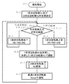
図3に示すように、まず、2段型スクリュ圧縮機2の運転が開始されると(ステップS3−1)、1段目回転数N1及び2段目回転数N2を初期設定する(ステップS3−2)。1段目回転数N1及び2段目回転数N2の初期値は、例えばそれぞれの定格回転数を採用してもよい。そして、吐出空気圧力を圧力センサ24により測定し、吐出空気圧力の測定値が所定範囲内であるか否かを1段目回転数決定部25により判定する(ステップS3−3)。ここでの所定範囲とは、供給先の要求圧力を満たす圧縮空気を供給可能とする吐出空気圧力の範囲である。吐出空気圧力が所定範囲より高い場合、1段目回転数N1を所定回転数ΔNだけ低下させ(ステップS3−4)、再び吐出空気圧力が所定範囲内であるか否かを判定する(ステップS3−3)。吐出空気圧力が所定範囲より低い場合、1段目回転数N1を所定回転数ΔNだけ上昇させ(ステップS3−5)、再び吐出空気圧力が所定範囲内であるか否かを判定する(ステップS3−3)。吐出空気圧力が所定範囲内である場合、1段目回転数N1を決定し、第1インバータ制御部26は1段目回転数決定部25により決定された1段目回転数N1となるように第1インバータ14を制御する(ステップS3−6)。
As shown in FIG. 3, when the operation of the two-
次に、探索部27により2段目回転数N2を探索する(ステップS3−7)。この探索に関するサブルーチンは図4を参照して後述する。そして、第2インバータ制御部28は、探索部27により探索された総消費電力Wを最小化する最適2段目回転数N2optとなるように第2インバータ20を制御する(ステップS3−8)。これらの処理を完了後、再び吐出空気圧力が所定範囲内であるか否かを判定する(ステップS3−3)。
Next, the
図4に示すように、探索部27による2段目回転数N2の探索は行われる。2段目回転数N2の探索が開始されると(ステップS4−1)、2段目回転数N2を所定範囲の下限値に設定し(ステップS4−2)、総消費電力Wを測定してこのときの2段目回転数N2と総消費電力Wの組を記憶する(ステップS4−3)。2段目回転数N2の所定範囲とは、上述のように2段目圧縮機本体6の定常運転の範囲に対応する。そして、2段目回転数N2を所定回転数ΔNだけ増加させ(ステップS4−4)、2段目回転数N2が所定範囲の上限値を超えるまでステップS4−3及びステップS4−4の処理を繰り返す(ステップS4−5)。ステップS4−4の2段目回転数N2の増分ΔNは、図3のステップS3−3及びステップS3−4の所定回転数ΔNと値が異なってもよい。そして、総消費電力Wが最小のときの最適2段目回転数N2optを決定し(ステップS4−6)、探索を終了する(ステップS4−7)。
As shown in FIG. 4, the search for the second stage rotation speed N2 by the
図5は、このように探索部27により記憶した2段目回転数N2とそれに対応する総消費電力Wとをグラフにプロットしたものである。探索部27では、グラフ上の最小点である総消費電力Wが最小となる最適2段目回転数N2optを探索する。
FIG. 5 is a graph in which the second-stage rotation speed N2 stored by the
また、図4に示す2段目回転数N2の探索方法は単なる例示であり、その他の方法で総消費電力Wを最小化する最適2段目回転数N2optを探索してもよい。例えば、本実施形態のように測定した2段目回転数N2と総消費電力Wの組を全て記憶せずとも、新たに総消費電力Wを測定するごとに、それまでの総消費電力Wの最小値と比較し、最も総消費電力Wが小さい2段目回転数N2のみを記憶してもよい。この場合、最終的に記憶されている2段目回転数N2が総消費電力Wを最小化する最適2段目回転数N2optとなる。 Further, the search method for the second-stage rotation speed N2 shown in FIG. 4 is merely an example, and the optimum second-stage rotation speed N2opt that minimizes the total power consumption W may be searched by other methods. For example, every time the total power consumption W is newly measured without storing all the sets of the second-stage rotation speed N2 and the total power consumption W measured as in the present embodiment, Only the second-stage rotation speed N2 having the smallest total power consumption W compared to the minimum value may be stored. In this case, the second-stage rotation speed N2 that is finally stored is the optimum second-stage rotation speed N2opt that minimizes the total power consumption W.
図3及び図4の制御フローに示すように制御することで、2段型スクリュ圧縮機2において、1段目回転数を調整することにより要求圧力を実現すると共に、2段目回転数を調整することにより総消費電力を最小化できる。また、総消費電力を最小化する最適2段目回転数の探索を自動的に行うことができる。さらに、所定範囲内で2段目回転数を実際に変更して総消費電力を検出するため、総消費電力を最小化する最適2段目回転数を確実に探索できる。なお、空気の圧力と体積の積である重量流量は圧縮過程において一定であるため、1段目回転数による要求圧力の実現後に2段目回転数を変更しても要求圧力は実現できる構成となっている。
By controlling as shown in the control flow of FIG. 3 and FIG. 4, in the two-
本実施形態では、探索部27による探索の際、総消費電力を最小化する制御を行ったが、制御対象は消費電力に限定されない。例えば、総消費電力に代えて1段目圧縮機本体4及び2段目圧縮機本体6の動力や電流を最小化する制御を行ってもよい。これは以降の第2及び第3実施形態でも同様である。
In the present embodiment, the control for minimizing the total power consumption is performed during the search by the
(第2実施形態)
本実施形態の2段型スクリュ圧縮機2の構成は、図1に示す第1実施形態の構成と同一である。また、図6は、第1実施形態における図2に対応する第2実施形態の2段型スクリュ圧縮機2の制御装置8のブロック図を示している。本実施形態は、第1実施形態の探索部27が記憶部(2段目回転数決定部)29に置換されたことに関する以外は第1実施形態と実質的に同様である。従って、第1実施形態と同様の部分については説明を省略する場合がある。
(Second Embodiment)
The configuration of the two-
図6に示すように、本実施形態の2段型スクリュ圧縮機2の制御装置8は、1段目回転数に対して総消費電力が最小となる最適2段目回転数を予め記憶した記憶部29を備える。制御装置8は、第2インバータ制御部28で2段目回転数を変更する際、1段目回転数に対して記憶部29で記憶した最適2段目回転数を採用する。
As shown in FIG. 6, the
図7に示すのは、1段目回転数比に対する総消費電力を最小化する2段目回転数比のグラフである。グラフ中の縦軸及び横軸の100%は、第1モータ12及び第2モータ18の回転数が許容回転数の最大値に達したことを表す。グラフ中、複数の線が描かれているのは、圧縮機本体4,6のスクリュロータのサイズや圧縮時の温度などの条件により、1段目回転数比に対する最適2段目回転数が変わるためである。記憶部29は、図7のように種々の条件に対して予め実験等により求めた最適2段目回転数を記憶している。なお、図7に示したグラフは単なる例示であり、図7に示したグラフに基づいて最適2段目回転数の決定方法が限定されることはない。
FIG. 7 is a graph of the second stage rotational speed ratio that minimizes the total power consumption relative to the first stage rotational speed ratio. 100% of the vertical axis and the horizontal axis in the graph indicates that the rotation speeds of the
図8に示すのは、本実施形態の2段型スクリュ圧縮機2の制御フローである。本実施形態では、ステップS8−7の処理以外は図3の第1実施形態と実質的に同様である。ステップS8−7の処理では、記憶部29で記憶した2段目回転数N2を採用している。従って、要求圧力に応じて必要な1段目回転数N1が決まると、総消費電力Wを最小化する最適2段目回転数N2optを予め記憶しているため、運転中に2段目回転数N2を探索することなく即時に決定できる
FIG. 8 shows a control flow of the two-
(第3実施形態)
本実施形態の2段型スクリュ圧縮機2の構成は図1に示す第1実施形態の構成と同一である。また、図9は、第1実施形態における図2に対応する第3実施形態の2段型スクリュ圧縮機2の制御装置8のブロック図を示している。図10及び図11は、第1実施形態における図3及び図4に対応する第3実施形態の2段型スクリュ圧縮機2の制御装置8の制御フローを示している。本実施形態の2段型スクリュ圧縮機2は、第1実施形態の1段目回転数及び2段目回転数に関する制御が入れ替えられていることに関する以外は第1実施形態と実質的に同様である。従って、第1実施形態と同様の部分については説明を省略する場合がある。
(Third embodiment)
The configuration of the two-
図9に示すように、本実施形態の2段型スクリュ圧縮機2の制御装置8は、2段目回転数決定部27において要求圧力に応じた吐出圧力となるように2段目回転数を決定する。第2インバータ制御部28は、2段目回転数決定部27で決定された2段目回転数となるように第2インバータ20を制御する。また、探索部(1段目回転数決定部)25は、第1モータ12及び第2モータ18からの測定値である総消費電力に基づいて、1段目回転数のうち総消費電力を最小化する最適1段目回転数を探索する。具体的な探索方法は第1実施形態の最適2段目回転数の探索と同様である。
As shown in FIG. 9, the
図10及び図11に示すように、本実施形態の制御フローは、図3及び図4に示す第1実施形態の制御フローから1段目回転数N1と2段目回転数N2についての記載が入れ替わっている。また、図10のサブルーチン処理においても同様に、図4に示す第1実施形態のサブルーチン処理から1段目回転数N1と2段目回転数N2についての記載が入れ替わっている。従って、本実施形態では第1実施形態と異なり2段目回転数の決定後に1段目回転数が決定される。 As shown in FIGS. 10 and 11, the control flow of the present embodiment describes the first-stage rotation speed N1 and the second-stage rotation speed N2 from the control flow of the first embodiment shown in FIGS. 3 and 4. It has been replaced. Similarly, in the subroutine processing of FIG. 10, the descriptions about the first-stage rotation speed N1 and the second-stage rotation speed N2 are switched from the subroutine processing of the first embodiment shown in FIG. Therefore, in the present embodiment, unlike the first embodiment, the first-stage rotation speed is determined after the determination of the second-stage rotation speed.
このように、探索の際に1段目回転数と2段目回転数のいずれの回転数を先に決定するかは限定されない。 As described above, there is no limitation on which of the first-stage rotation speed and the second-stage rotation speed is determined first in the search.
以上より本発明の具体的な実施形態について説明したが、本発明は上記実施形態に限定されるものではなく、この発明の範囲内で種々変更して実施することができる。例えば、上記第1から第3実施形態で記載した内容を適宜組み合わせたものを、この発明の一実施形態としてもよい。 Although specific embodiments of the present invention have been described above, the present invention is not limited to the above-described embodiments, and various modifications can be made within the scope of the present invention. For example, what combined suitably the content described in the said 1st-3rd embodiment is good also as one Embodiment of this invention.
2 2段型スクリュ圧縮機
4 1段目圧縮機本体
4a 吸気口
4b 吐出口
6 2段目圧縮機本体
6a 吸気口
6b 吐出口
8 制御装置
10a 第1空気配管
10b 第2空気配管
10c 第3空気配管
12 第1モータ(第1電動機)
14 第1インバータ
16 インタークーラ
18 第2モータ(第2電動機)
20 第2インバータ
22 アフタークーラ
24 圧力センサ
25 1段目回転数決定部(探索部)
26 第1インバータ制御部
27 探索部(2段目回転数決定部)
28 第2インバータ制御部
29 記憶部(2段目回転数決定部)
2 Second
14
20
26 1st
28 Second
Claims (6)
第2インバータで回転数を変更可能である第2電動機により駆動され、前記1段目圧縮機本体の下流側に直列に接続された2段目圧縮機本体と、
要求圧力に応じて1段目回転数を決定する1段目回転数決定部と、前記1段目回転数決定部により決定された前記1段目回転数となるように前記第1インバータを制御する第1インバータ制御部と、2段目回転数のうち前記第1電動機および前記第2電動機の総消費電力を最小化する最適2段目回転数を決定する2段目回転数決定部と、前記最適2段目回転数となるように前記第2インバータを制御する第2インバータ制御部とを有する制御装置と
を備え、
前記2段目回転数決定部は、所定範囲内で前記2段目回転数を自動的に変化させて個々の前記2段目回転数に対応する前記総消費電力を検出し、前記最適2段目回転数を探索する、2段型スクリュ圧縮機。 A first-stage compressor body driven by a first electric motor whose rotation speed can be changed by a first inverter;
A second stage compressor body driven by a second electric motor capable of changing the rotational speed by a second inverter and connected in series to the downstream side of the first stage compressor body;
A first-stage rotation speed determination unit that determines the first-stage rotation speed according to the required pressure, and the first inverter is controlled so as to be the first-stage rotation speed determined by the first-stage rotation speed determination unit. A first inverter control unit, a second stage rotational speed determination unit that determines an optimal second stage rotational speed that minimizes total power consumption of the first electric motor and the second motor among the second stage rotational speeds, A control device having a second inverter control unit for controlling the second inverter so as to achieve the optimum second stage rotational speed ,
The second-stage rotation speed determination unit automatically changes the second-stage rotation speed within a predetermined range to detect the total power consumption corresponding to each of the second-stage rotation speeds, and A two-stage screw compressor that searches for the number of eye rotations .
前記2段目回転数を定常運転の範囲の下限値に設定し、前記総消費電力を測定してこのときの前記2段目回転数と前記総消費電力の組を記憶し、 Set the second stage rotational speed to the lower limit of the range of steady operation, measure the total power consumption, and store the set of the second stage rotational speed and the total power consumption at this time,
前記2段目回転数を所定回転数だけ増加させ、前記総消費電力を測定してこのときの前記2段目回転数と前記総消費電力の組を記憶し、 Increase the second stage rotational speed by a predetermined rotational speed, measure the total power consumption, and store the set of the second stage rotational speed and the total power consumption at this time,
前記2段目回転数が定常運転の範囲の上限値を超えるまでこの処理を繰り返すことで、前記最適2段目回転数を決定する、請求項1に記載の2段型スクリュ圧縮機。 2. The two-stage screw compressor according to claim 1, wherein the optimum second-stage rotation speed is determined by repeating this process until the second-stage rotation speed exceeds an upper limit value of a range of steady operation.
第2インバータで回転数を変更可能である第2電動機により駆動され、前記1段目圧縮機本体の下流側に直列に接続された2段目圧縮機本体と、
要求圧力に応じて2段目回転数を決定する2段目回転数決定部と、前記2段目回転数決定部により決定された前記2段目回転数となるように前記第2インバータを制御する第2インバータ制御部と、1段目回転数のうち総消費電力を最小化する最適1段目回転数を決定する1段目回転数決定部と、前記最適1段目回転数となるように前記第1インバータを制御する第1インバータ制御部とを有する制御装置と
を備え、
前記1段目回転数決定部は、所定範囲内で前記1段目回転数を自動的に変化させて個々の前記1段目回転数に対応する前記総消費電力を検出し、前記最適1段目回転数を探索する、2段型スクリュ圧縮機。 A first-stage compressor body driven by a first electric motor whose rotation speed can be changed by a first inverter;
A second stage compressor body driven by a second electric motor capable of changing the rotational speed by a second inverter and connected in series to the downstream side of the first stage compressor body;
A second-stage rotational speed determination unit that determines the second-stage rotational speed according to the required pressure, and the second inverter is controlled so that the second-stage rotational speed is determined by the second-stage rotational speed determination unit. A second inverter control unit that performs the first-stage rotation speed determination unit that determines the optimal first-stage rotation speed that minimizes the total power consumption among the first-stage rotation speeds, and the optimal first-stage rotation speed. And a control device having a first inverter control unit for controlling the first inverter ,
The first-stage rotational speed determination unit automatically changes the first-stage rotational speed within a predetermined range to detect the total power consumption corresponding to each of the first-stage rotational speeds, and the optimal first-stage rotational speed is determined. A two-stage screw compressor that searches for the number of eye rotations .
前記1段目回転数を定常運転の範囲の下限値に設定し、前記総消費電力を測定してこのときの前記1段目回転数と前記総消費電力の組を記憶し、 The first stage rotational speed is set to the lower limit value of the range of steady operation, the total power consumption is measured, and the set of the first stage rotational speed and the total power consumption at this time is stored.
前記1段目回転数を所定回転数だけ増加させ、前記総消費電力を測定してこのときの前記1段目回転数と前記総消費電力の組を記憶し、 Increase the first stage rotational speed by a predetermined rotational speed, measure the total power consumption, and store the set of the first stage rotational speed and the total power consumption at this time,
前記1段目回転数が定常運転の範囲の上限値を超えるまでこの処理を繰り返すことで、前記最適1段目回転数を決定する、請求項3に記載の2段型スクリュ圧縮機。 The two-stage screw compressor according to claim 3, wherein the optimum first-stage rotation speed is determined by repeating this process until the first-stage rotation speed exceeds an upper limit value of a steady operation range.
第2インバータで回転数を変更可能である第2電動機により駆動され、前記1段目圧縮機本体の下流側に直列に接続された2段目圧縮機本体と
を設け、
要求圧力に応じた1段目回転数を決定し、
この1段目回転数となるように前記第1インバータを制御し、
所定範囲内で2段目回転数を変化させて個々の前記2段目回転数に対応する前記総消費電力を検出し、前記2段目回転数のうち前記第1電動機および前記第2電動機の総消費電力を最小化する最適2段目回転数を探索および決定し、
この最適2段目回転数となるように前記第2インバータを制御する、2段型スクリュ圧縮機の運転方法。 A first-stage compressor body driven by a first electric motor whose rotation speed can be changed by a first inverter;
A second stage compressor body driven by a second electric motor whose rotation speed can be changed by a second inverter and connected in series downstream of the first stage compressor body;
Determine the first stage rotation speed according to the required pressure,
The first inverter is controlled to achieve the first stage rotational speed;
The total power consumption corresponding to each of the second-stage rotation speeds is detected by changing the second-stage rotation speed within a predetermined range, and the first electric motor and the second electric motor among the second-stage rotation speeds are detected. Search and determine the optimal second stage rotation speed that minimizes the total power consumption,
A method for operating a two-stage screw compressor, wherein the second inverter is controlled to achieve the optimum second-stage rotation speed.
第2インバータで回転数を変更可能である第2電動機により駆動され、前記1段目圧縮機本体の下流側に直列に接続された2段目圧縮機本体と、
を設け、
要求圧力に応じた2段目回転数を決定し、
この2段目回転数となるように前記第2インバータを制御し、
所定範囲内で1段目回転数を変化させて個々の前記1段目回転数に対応する前記総消費電力を検出し、前記1段目回転数のうち前記第1電動機および前記第2電動機の総消費電力を最小化する最適1段目回転数を探索および決定し、
この最適1段目回転数となるように前記第1インバータを制御する、2段型スクリュ圧縮機の運転方法。 A first-stage compressor body driven by a first electric motor whose rotation speed can be changed by a first inverter;
A second stage compressor body driven by a second electric motor capable of changing the rotational speed by a second inverter and connected in series to the downstream side of the first stage compressor body;
Provided,
Determine the second stage rotation speed according to the required pressure,
Controlling the second inverter so as to achieve the second stage rotational speed;
The total power consumption corresponding to each of the first stage rotational speeds is detected by changing the first stage rotational speed within a predetermined range, and the first electric motor and the second electric motor among the first stage rotational speeds Search and determine the optimal first stage rotation speed that minimizes the total power consumption,
A method for operating a two-stage screw compressor, wherein the first inverter is controlled to achieve the optimum first-stage rotation speed.
Priority Applications (4)
| Application Number | Priority Date | Filing Date | Title |
|---|---|---|---|
| JP2015169409A JP6491982B2 (en) | 2015-08-28 | 2015-08-28 | Two-stage screw compressor and operating method thereof |
| PCT/JP2016/071906 WO2017038308A1 (en) | 2015-08-28 | 2016-07-26 | Two-stage screw compressor and method for operating same |
| CN201680050487.1A CN107923402B (en) | 2015-08-28 | 2016-07-26 | Two-stage screw compressor and method of operating the same |
| TW105125310A TWI631282B (en) | 2015-08-28 | 2016-08-09 | Two-stage screw compressor and its operating method |
Applications Claiming Priority (1)
| Application Number | Priority Date | Filing Date | Title |
|---|---|---|---|
| JP2015169409A JP6491982B2 (en) | 2015-08-28 | 2015-08-28 | Two-stage screw compressor and operating method thereof |
Publications (2)
| Publication Number | Publication Date |
|---|---|
| JP2017044195A JP2017044195A (en) | 2017-03-02 |
| JP6491982B2 true JP6491982B2 (en) | 2019-03-27 |
Family
ID=58187087
Family Applications (1)
| Application Number | Title | Priority Date | Filing Date |
|---|---|---|---|
| JP2015169409A Active JP6491982B2 (en) | 2015-08-28 | 2015-08-28 | Two-stage screw compressor and operating method thereof |
Country Status (4)
| Country | Link |
|---|---|
| JP (1) | JP6491982B2 (en) |
| CN (1) | CN107923402B (en) |
| TW (1) | TWI631282B (en) |
| WO (1) | WO2017038308A1 (en) |
Families Citing this family (1)
| Publication number | Priority date | Publication date | Assignee | Title |
|---|---|---|---|---|
| CN111720298B (en) * | 2020-06-11 | 2022-06-14 | 厦门东亚机械工业股份有限公司 | Two-stage compression control method and controller of air compressor and air compressor |
Family Cites Families (6)
| Publication number | Priority date | Publication date | Assignee | Title |
|---|---|---|---|---|
| US5347467A (en) * | 1992-06-22 | 1994-09-13 | Compressor Controls Corporation | Load sharing method and apparatus for controlling a main gas parameter of a compressor station with multiple dynamic compressors |
| JPH1137053A (en) * | 1997-07-23 | 1999-02-09 | Ishikawajima Harima Heavy Ind Co Ltd | Control method for inverter drive multistage compressor |
| BE1012944A3 (en) * | 1999-10-26 | 2001-06-05 | Atlas Copco Airpower Nv | MULTISTAGE COMPRESSOR UNIT AND METHOD FOR CONTROLLING ONE OF EQUAL MORE stage compressor unit. |
| GB2367332B (en) * | 2000-09-25 | 2003-12-03 | Compair Uk Ltd | Improvements in multi-stage screw compressor drive arrangements |
| JP5689385B2 (en) * | 2011-08-12 | 2015-03-25 | 株式会社神戸製鋼所 | Compression device |
| JP2013209902A (en) * | 2012-03-30 | 2013-10-10 | Anest Iwata Corp | Compressed gas supply unit, compressed gas supply apparatus and control method therefor |
-
2015
- 2015-08-28 JP JP2015169409A patent/JP6491982B2/en active Active
-
2016
- 2016-07-26 WO PCT/JP2016/071906 patent/WO2017038308A1/en active Application Filing
- 2016-07-26 CN CN201680050487.1A patent/CN107923402B/en active Active
- 2016-08-09 TW TW105125310A patent/TWI631282B/en active
Also Published As
| Publication number | Publication date |
|---|---|
| WO2017038308A1 (en) | 2017-03-09 |
| JP2017044195A (en) | 2017-03-02 |
| CN107923402A (en) | 2018-04-17 |
| TW201719020A (en) | 2017-06-01 |
| CN107923402B (en) | 2020-03-27 |
| TWI631282B (en) | 2018-08-01 |
Similar Documents
| Publication | Publication Date | Title |
|---|---|---|
| JP5650204B2 (en) | Control system | |
| WO2021008146A1 (en) | Control method and apparatus for water pumps in air conditioning system, and air conditioning system | |
| WO2007095537A1 (en) | Multi-stage compression system and method of operating the same | |
| US20190011179A1 (en) | Boil-off gas supply device | |
| CN107238240A (en) | The control method and device of cooling by wind and its blower fan | |
| JP6491982B2 (en) | Two-stage screw compressor and operating method thereof | |
| JP5646282B2 (en) | Compressor and operation control method thereof | |
| JPH1082391A (en) | Control device of two-stage screw compressor | |
| JP6453484B2 (en) | Gas compressor | |
| CN113028682B (en) | Oil return control method and air conditioner | |
| US11808261B2 (en) | Variable capacity compressor operation mode determination method and device, variable capacity compressor, and air conditioner | |
| EP3051224B1 (en) | Refrigeration cycle device | |
| JP2004190583A (en) | Screw compressor | |
| JP2008248816A (en) | Compressor | |
| KR101948648B1 (en) | Turbo air compressor test apparatus | |
| JP2008507659A (en) | Dynamically controlled compressor | |
| JP2005023818A (en) | Compressor system | |
| JP4425768B2 (en) | Screw compressor | |
| CN211204486U (en) | Decide novel varactor heat pump system of variable frequency coupling | |
| CN211716917U (en) | Heat pump and optimal superheat degree control device thereof | |
| CN110887267A (en) | Decide novel varactor heat pump system of variable frequency coupling | |
| TWI663334B (en) | Inter-stage discharge air compressor | |
| JP2005226538A (en) | Air compressor and its control method | |
| JP5463339B2 (en) | Compressor system | |
| JP2004205163A (en) | Refrigerating plant |
Legal Events
| Date | Code | Title | Description |
|---|---|---|---|
| A621 | Written request for application examination |
Free format text: JAPANESE INTERMEDIATE CODE: A621 Effective date: 20170901 |
|
| A131 | Notification of reasons for refusal |
Free format text: JAPANESE INTERMEDIATE CODE: A131 Effective date: 20180731 |
|
| A521 | Written amendment |
Free format text: JAPANESE INTERMEDIATE CODE: A523 Effective date: 20180918 |
|
| TRDD | Decision of grant or rejection written | ||
| A01 | Written decision to grant a patent or to grant a registration (utility model) |
Free format text: JAPANESE INTERMEDIATE CODE: A01 Effective date: 20190226 |
|
| A61 | First payment of annual fees (during grant procedure) |
Free format text: JAPANESE INTERMEDIATE CODE: A61 Effective date: 20190304 |
|
| R151 | Written notification of patent or utility model registration |
Ref document number: 6491982 Country of ref document: JP Free format text: JAPANESE INTERMEDIATE CODE: R151 |
|
| S111 | Request for change of ownership or part of ownership |
Free format text: JAPANESE INTERMEDIATE CODE: R313111 |
|
| R350 | Written notification of registration of transfer |
Free format text: JAPANESE INTERMEDIATE CODE: R350 |