JP6489552B2 - How to find the dimensions in a scene - Google Patents
How to find the dimensions in a scene Download PDFInfo
- Publication number
- JP6489552B2 JP6489552B2 JP2016056626A JP2016056626A JP6489552B2 JP 6489552 B2 JP6489552 B2 JP 6489552B2 JP 2016056626 A JP2016056626 A JP 2016056626A JP 2016056626 A JP2016056626 A JP 2016056626A JP 6489552 B2 JP6489552 B2 JP 6489552B2
- Authority
- JP
- Japan
- Prior art keywords
- plane
- planes
- scene
- depth image
- sensor
- Prior art date
- Legal status (The legal status is an assumption and is not a legal conclusion. Google has not performed a legal analysis and makes no representation as to the accuracy of the status listed.)
- Active
Links
Images

Classifications
-
- G—PHYSICS
- G01—MEASURING; TESTING
- G01B—MEASURING LENGTH, THICKNESS OR SIMILAR LINEAR DIMENSIONS; MEASURING ANGLES; MEASURING AREAS; MEASURING IRREGULARITIES OF SURFACES OR CONTOURS
- G01B11/00—Measuring arrangements characterised by the use of optical techniques
-
- G—PHYSICS
- G06—COMPUTING OR CALCULATING; COUNTING
- G06T—IMAGE DATA PROCESSING OR GENERATION, IN GENERAL
- G06T7/00—Image analysis
- G06T7/60—Analysis of geometric attributes
- G06T7/62—Analysis of geometric attributes of area, perimeter, diameter or volume
-
- G—PHYSICS
- G06—COMPUTING OR CALCULATING; COUNTING
- G06F—ELECTRIC DIGITAL DATA PROCESSING
- G06F18/00—Pattern recognition
- G06F18/20—Analysing
- G06F18/23—Clustering techniques
- G06F18/231—Hierarchical techniques, i.e. dividing or merging pattern sets so as to obtain a dendrogram
-
- G—PHYSICS
- G06—COMPUTING OR CALCULATING; COUNTING
- G06T—IMAGE DATA PROCESSING OR GENERATION, IN GENERAL
- G06T7/00—Image analysis
- G06T7/10—Segmentation; Edge detection
- G06T7/12—Edge-based segmentation
-
- G—PHYSICS
- G06—COMPUTING OR CALCULATING; COUNTING
- G06T—IMAGE DATA PROCESSING OR GENERATION, IN GENERAL
- G06T7/00—Image analysis
- G06T7/70—Determining position or orientation of objects or cameras
- G06T7/73—Determining position or orientation of objects or cameras using feature-based methods
- G06T7/75—Determining position or orientation of objects or cameras using feature-based methods involving models
-
- G—PHYSICS
- G06—COMPUTING OR CALCULATING; COUNTING
- G06V—IMAGE OR VIDEO RECOGNITION OR UNDERSTANDING
- G06V10/00—Arrangements for image or video recognition or understanding
- G06V10/70—Arrangements for image or video recognition or understanding using pattern recognition or machine learning
- G06V10/762—Arrangements for image or video recognition or understanding using pattern recognition or machine learning using clustering, e.g. of similar faces in social networks
- G06V10/7625—Hierarchical techniques, i.e. dividing or merging patterns to obtain a tree-like representation; Dendograms
-
- G—PHYSICS
- G06—COMPUTING OR CALCULATING; COUNTING
- G06V—IMAGE OR VIDEO RECOGNITION OR UNDERSTANDING
- G06V20/00—Scenes; Scene-specific elements
- G06V20/10—Terrestrial scenes
-
- G—PHYSICS
- G06—COMPUTING OR CALCULATING; COUNTING
- G06T—IMAGE DATA PROCESSING OR GENERATION, IN GENERAL
- G06T2200/00—Indexing scheme for image data processing or generation, in general
- G06T2200/04—Indexing scheme for image data processing or generation, in general involving 3D image data
-
- G—PHYSICS
- G06—COMPUTING OR CALCULATING; COUNTING
- G06T—IMAGE DATA PROCESSING OR GENERATION, IN GENERAL
- G06T2207/00—Indexing scheme for image analysis or image enhancement
- G06T2207/10—Image acquisition modality
- G06T2207/10024—Color image
-
- G—PHYSICS
- G06—COMPUTING OR CALCULATING; COUNTING
- G06T—IMAGE DATA PROCESSING OR GENERATION, IN GENERAL
- G06T2207/00—Indexing scheme for image analysis or image enhancement
- G06T2207/10—Image acquisition modality
- G06T2207/10028—Range image; Depth image; 3D point clouds
-
- G—PHYSICS
- G06—COMPUTING OR CALCULATING; COUNTING
- G06T—IMAGE DATA PROCESSING OR GENERATION, IN GENERAL
- G06T2207/00—Indexing scheme for image analysis or image enhancement
- G06T2207/30—Subject of image; Context of image processing
- G06T2207/30244—Camera pose
Landscapes
- Engineering & Computer Science (AREA)
- Theoretical Computer Science (AREA)
- Physics & Mathematics (AREA)
- General Physics & Mathematics (AREA)
- Computer Vision & Pattern Recognition (AREA)
- Data Mining & Analysis (AREA)
- Evolutionary Computation (AREA)
- Multimedia (AREA)
- Artificial Intelligence (AREA)
- Geometry (AREA)
- Life Sciences & Earth Sciences (AREA)
- Bioinformatics & Computational Biology (AREA)
- Computing Systems (AREA)
- Health & Medical Sciences (AREA)
- Software Systems (AREA)
- General Health & Medical Sciences (AREA)
- Bioinformatics & Cheminformatics (AREA)
- Databases & Information Systems (AREA)
- Evolutionary Biology (AREA)
- General Engineering & Computer Science (AREA)
- Medical Informatics (AREA)
- Length Measuring Devices By Optical Means (AREA)
- Image Analysis (AREA)
- Measurement Of Optical Distance (AREA)
Description
本発明は、包括的には、コンピュータービジョンに関し、より詳細には、屋内シーンの寸法を求めることに関する。 The present invention relates generally to computer vision and more particularly to determining indoor scene dimensions.
部屋及び廊下等の屋内シーンの寸法情報は、多種多様な用途において有益とすることができる。建物の建築中に、構造物を監視して、その構造物が仕様書及び図面の要件を満たすことを確実にするように寸法情報を用いることができる。建物の保守管理中に、寸法情報は、構造物が現行の建築基準法(building codes)に沿っているか否かを判断することができ、欠陥、例えばひび割れが存在する場合には、それらの欠陥を数量化することができる。加えて、建設自動化との関係では、寸法情報は、建設中にロボットが行う、窓の取り付け等の任意のタスクにおいて有益である。 Dimensional information for indoor scenes such as rooms and corridors can be useful in a wide variety of applications. During building construction, dimensional information can be used to monitor the structure and ensure that the structure meets the specifications and drawing requirements. During building maintenance, the dimensional information can determine whether the structure is in line with current building codes and, if there are defects, such as cracks, those defects. Can be quantified. In addition, in the context of construction automation, dimensional information is useful for any task, such as window installation, performed by a robot during construction.
窓取り付けロボットの場合、このロボットは、公差の不一致に起因して、窓枠の設計サイズではなく、建設された窓枠の実際のサイズを知る必要がある。ロボットは、この寸法情報を用いて、窓を正しく取り付けることができ、その窓が枠内に正確に収まることを確実にすることができる。加えて、自律ロボットが屋内環境を移動するためには、任意の開口の寸法が非常に重要である。例えば、ロボットは、ドアを通る際に、そのドアをそのまま通るか、又は別の方法を用いるかを自動的に判断することができるように、開口空間の寸法を検知する必要がある。 In the case of a window mounting robot, the robot needs to know the actual size of the constructed window frame, not the design size of the window frame, due to tolerance mismatch. The robot can use this dimensional information to correctly attach the window and ensure that the window fits precisely within the frame. In addition, for an autonomous robot to move in an indoor environment, the size of any aperture is very important. For example, when a robot passes through a door, the robot needs to detect the size of the opening space so that it can automatically determine whether to pass the door as it is or to use another method.
従来技術において、屋内シーンの3次元(3D)モデルを生成し、3Dモデル内の寸法を測定するのに、回転レーザーを使用する3Dセンサーが一般的に用いられてきた。それらのセンサーは、単一のロケーションから長距離及び360度カバレッジで3Dモデルを生成することができる。しかしながら、それらのセンサーは高価であり、長い走査時間を要する。この長い走査時間の間、それらのセンサーは定位置に置かれている必要がある。 In the prior art, 3D sensors that use a rotating laser have been commonly used to generate a three-dimensional (3D) model of an indoor scene and measure dimensions within the 3D model. Those sensors can generate 3D models with long distance and 360 degree coverage from a single location. However, these sensors are expensive and require long scanning times. During this long scan time, the sensors need to be in place.
近年、短距離及び狭視野カバレッジを有する3Dセンサーを容易に入手することができる。それらのセンサーは、単発のリアルタイム走査を可能にする。それらのセンサーを用いて大規模3Dモデルを生成する場合、1つの方法は、同時ローカリゼーション及びマッピング(SLAM:simultaneous localization and mapping:同時位置推定地図構築)技法を用いて、それらのセンサーにより取得された複数のフレームを位置合わせする。しかしながら、その方法は、位置合わせにおいてドリフトエラーを累積し、結果として寸法測定値の精度が低下する。 In recent years, 3D sensors with short range and narrow field coverage can be readily obtained. These sensors allow a single real-time scan. When generating large-scale 3D models using these sensors, one method was acquired by those sensors using simultaneous localization and mapping (SLAM) techniques. Align multiple frames. However, that method accumulates drift errors in alignment, resulting in a decrease in the accuracy of the dimension measurements.
ユーザーインタラクションの観点から、1つの方法は、データに素早くアクセスするようにユーザーインタラクションを用いた建設品質(construction quality:施工品質)検査及び管理システムを提供する。インタラクティブシミュレーションモデリングの別の方法は、シミュレーションモデルを構築するための、ステップごとのガイダンスをユーザーに提供する。ユーザーガイダンスは、ユーザーの指導者としての役割を果たす。更に別の方法は、参照画像を所与として、参照画像が撮像された視点と同じ視点から画像を撮像するためのガイダンスをユーザーに提供する。 From a user interaction perspective, one method provides a construction quality inspection and management system that uses user interaction to quickly access data. Another method of interactive simulation modeling provides the user with step-by-step guidance for building a simulation model. User guidance serves as the user's mentor. Yet another method provides a user with guidance for capturing an image from the same viewpoint from which the reference image was captured given a reference image.
多くの土木工学タスクでは、人工構造物を含む屋内シーン等のシーンの寸法解析が、空間解析及び意思決定において重要である。竣工形状生成(as-built geometry generation)等のタスクは、様々な位置から収集されたデータに基づいて、散らかっている可能性のあるシーン内の特定のオブジェクト(例えば、パイプの直径、開口の幅)の限界寸法を効率的に解釈する必要がある。 In many civil engineering tasks, dimensional analysis of scenes such as indoor scenes including man-made structures is important in spatial analysis and decision making. Tasks such as as-built geometry generation are based on data collected from various locations, and specific objects in the scene that may be messy (for example, pipe diameter, opening width) ) Must be interpreted efficiently.
したがって、本発明の1つの実施形態は、奥行きセンサーにより取得された単一奥行き画像から、屋内シーン内の寸法を求める方法を提供する。 Accordingly, one embodiment of the present invention provides a method for determining dimensions in an indoor scene from a single depth image acquired by a depth sensor.
奥行きセンサーは、シーンの奥行き画像を取得する3Dセンサーである。奥行き画像は、各画素が奥行き(又はセンサーからシーンまでの距離)を表す2次元画像である。センサーの内部パラメーターを用いて、各画素につきレイを逆投影し、測定された奥行きにおいて3D点を生成することにより、奥行き画像を3D点群に変換することができる。奥行き画像を輝度(intensity)又は色、例えば、赤、緑、及び青(RGB)の画像と組み合わせると、RGB−D画像(すなわち、3D色付き点群)を取得することができる。 The depth sensor is a 3D sensor that acquires a depth image of a scene. The depth image is a two-dimensional image in which each pixel represents the depth (or the distance from the sensor to the scene). The depth image can be converted to a 3D point cloud by backprojecting the ray for each pixel using the sensor's internal parameters and generating 3D points at the measured depth. When a depth image is combined with an intensity or color image, eg, red, green, and blue (RGB), an RGB-D image (ie, a 3D colored point cloud) can be obtained.
次に、平面を抽出して幾何解析を行うことにより、単一奥行き画像から、シーン内の対象となる構造物の寸法を取得することができる。本方法は、寸法データ及び測定値の品質を評価し、例えばグラフィカルユーザーインターフェース(GUI)を用いて、異なる姿勢にセンサーを位置決めしてより高品質のデータを取得するためのインタラクティブガイダンスをもたらす。このより高品質のデータから、より正確な形状測定値を取得することができる。本明細書において規定されるように、姿勢は、3つの並進成分と、3つの回転成分との6次元(6D)を有する。 Next, by extracting a plane and performing geometric analysis, the dimensions of the target structure in the scene can be acquired from the single depth image. The method evaluates the quality of the dimensional data and measurements and provides interactive guidance to position the sensor in different poses and obtain higher quality data using, for example, a graphical user interface (GUI). More accurate shape measurements can be obtained from this higher quality data. As defined herein, the pose has six dimensions (6D) of three translational components and three rotational components.
本発明は、奥行きセンサーから屋内シーンの寸法を取得することが可能なユーザー誘導型寸法解析手法を部分的に用いる。奥行きセンサーから取得された単一奥行き画像に対して寸法解析を行い、高い計算効率を達成し、SLAM技法を用いたマルチフレーム位置合わせにおけるエラー累積を回避する。 The present invention partially uses a user-guided dimensional analysis technique that can obtain the dimensions of an indoor scene from a depth sensor. Dimension analysis is performed on a single depth image acquired from a depth sensor to achieve high computational efficiency and avoid error accumulation in multi-frame alignment using SLAM techniques.
センサーの視野が限られていることに起因して、単一奥行き画像は、対象となる全ての寸法情報を求めることができることを保証することはできない。加えて、求められた寸法の品質は、センサーの内在精度によって制限される。 Due to the limited field of view of the sensor, a single depth image cannot guarantee that all dimensional information of interest can be determined. In addition, the required dimensional quality is limited by the inherent accuracy of the sensor.
したがって、単一奥行き画像を用いることの不利点を克服するために、センサーをより良い姿勢に再位置決めするようにユーザー(又は、センサーが載置されているロボット)を誘導し、それにより寸法解析に適切な十分で高品質なデータが収集されるように、知識ベースのユーザーガイダンスシステムが開発される。高品質な単一画像データが収集された後、必要な寸法情報を取得するように幾何解析が行われる。 Therefore, to overcome the disadvantages of using a single depth image, the user (or the robot on which the sensor is mounted) is guided to reposition the sensor to a better posture, thereby dimensional analysis A knowledge-based user guidance system is developed so that sufficient and high-quality data appropriate for the system is collected. After high quality single image data is collected, geometric analysis is performed to obtain the necessary dimensional information.
本方法は、奥行き画像のシーケンスに対してではなく、単一奥行き画像に対して直接行われるので、本発明者らによる手法は従来技術とは異なる。単一奥行き画像を用いることで、屋内シーンの寸法情報のリアルタイム推定が可能になる。これは、自動化及びロボット工学に焦点を置いた幾つかの用途にとって重要である。 Since the method is performed directly on a single depth image, not on a sequence of depth images, the technique by the inventors is different from the prior art. By using a single depth image, it is possible to estimate the dimension information of the indoor scene in real time. This is important for some applications that focus on automation and robotics.
さらに、従来技術の手法とは異なり、本発明者らによるユーザーガイダンスシステムは、現在の画像のデータ品質を評価し、次に、その用途にとってのより良い結果を取得するためにセンサーを再位置決めすることをユーザーに提案する。本システムは、シンプルなガイダンスにより、ユーザーが高品質データ、及びしたがって高品質な寸法測定値を取得するように導くことができる。ユーザーは、専門家である必要がない。 Furthermore, unlike prior art approaches, the user guidance system by the inventors evaluates the data quality of the current image and then repositions the sensor to obtain better results for its application Propose to the user. The system can guide the user to obtain high quality data and thus high quality dimensional measurements with simple guidance. The user need not be an expert.
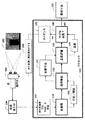
図1に示すように、本発明の実施形態は、単一奥行き画像101によって表される屋内シーン103内の寸法を求める方法を提供する。奥行き画像は、奥行きセンサー102により取得することができる。本発明の焦点は、平面を有する、屋内の基礎構造(infrastructure:インフラストラクチャー)の寸法解析に置かれている。シーンは、結合タイプ、例えば、部屋又は廊下を含むことができる。このタイプは、箱又は開口等の所定の形状を画定することができる。
As shown in FIG. 1, embodiments of the present invention provide a method for determining a dimension within an
幾つかの実施形態では、屋内シーンの3D点群を取得する奥行きセンサーとして、XboxセンサーのためのKinect(商標)が使用される。Kinectは、赤外線(IR)カメラ及びカラー(RGB)カメラを備えるので、シーンの奥行き画像及びカラー画像を取得することができる。したがって、全てではないが幾つかの実施形態では、センサー較正を用いることによって奥行き画像をカラー画像と位置合わせし(104)、RGB−D画像101を取得することができる。
In some embodiments, Kinect ™ for the Xbox sensor is used as a depth sensor to acquire a 3D point cloud of an indoor scene. Kinect includes an infrared (IR) camera and a color (RGB) camera, so it can acquire a depth image and a color image of the scene. Thus, in some but not all embodiments, the depth image can be aligned with the color image (104) and the RGB-
前処理110が奥行き画像又はRGB−D画像101に行われる。前処理は、平面を抽出することと、これらの平面の位相関係111を求めることとを含む。これらの平面及びそれらの関係に基づいて、幾何解析120を行い、シーンの初期寸法121を求める。
Preprocessing 110 is performed on the depth image or the RGB-
シーンタイプ及び初期寸法測定値を用いて、画像及び初期寸法の品質131が評価される(130)。品質が十分であれば(140)、最終寸法105が出力される。そうでない場合、より良い寸法を取得するためにデータの品質を改善するようにガイダンス141が出力される。例えば、ガイダンスは、センサーにとってのより良い姿勢142を示すことができる。出力は、ユーザーにセンサーを手動で再位置決めさせるか、ロボットに自動的に再位置決めさせるものとすることができる。
Using the scene type and initial dimension measurements, the
本方法のステップは、プロセッサ100において行うことができる。プロセッサ100は、当技術分野で既知のバスにより、本方法が用いる画像及び他のデータストラクチャーを記憶するためのメモリ並びに入出力インターフェースに接続されている。本質的には、本方法は、現実世界のオブジェクト、例えば、屋内シーン内の構造物の奥行き画像をそれらのオブジェクトの寸法に変換する。 The steps of the method may be performed in the processor 100. The processor 100 is connected to memory and input / output interfaces for storing images and other data structures used by the method by buses known in the art. In essence, the method converts depth images of real-world objects, such as structures in an indoor scene, into the dimensions of those objects.
屋内シーン及び平面
多くの屋内シーンは、平面に囲まれている。この前提に基づいて、幾何解析を行い、特定の基礎構造の寸法情報を取得する。効率的に平面を抽出するには、平面抽出プロシージャーが奥行き画像に適用される。例えば、Feng他「Fast plane extraction in organized point clouds using agglomerative hierarchical clustering」IEEE International Conference on Robotics and Automation (ICRA), pp. 6218-6225, 2014を参照されたい。
Indoor scenes and planes Many indoor scenes are surrounded by planes. Based on this assumption, geometric analysis is performed to obtain dimension information of a specific foundation structure. To extract the plane efficiently, a plane extraction procedure is applied to the depth image. See, for example, Feng et al. “Fast plane extraction in organized point clouds using agglomerative hierarchical clustering” IEEE International Conference on Robotics and Automation (ICRA), pp. 6218-6225, 2014.
奥行き画像内の画素は、グラフを構築するのに用いられる群にセグメント化される。これらの群はノードにより表され、エッジは隣接する群を表す。次に、このグラフに凝集型階層的クラスタリングを行い、同一平面上のノードを結合する。これらの平面は、画素単位の領域拡張により改良される。 The pixels in the depth image are segmented into groups that are used to construct the graph. These groups are represented by nodes and edges represent adjacent groups. Next, agglomerative hierarchical clustering is performed on this graph to connect nodes on the same plane. These planes are improved by area expansion on a pixel basis.
カラー画像が奥行き画像とともに利用可能である場合、すなわち、RGB−D画像が使用される場合、色情報を用いて平面を更にセグメント化することができる。例えば、各平面に現れる色をクラスタリングすることができ、これらのクラスターに基づいて平面がセグメント化される。 If a color image is available with a depth image, i.e. if an RGB-D image is used, the color information can be used to further segment the plane. For example, the colors that appear in each plane can be clustered, and the planes are segmented based on these clusters.
奥行き画像から全ての平面を抽出した後、平面パラメーターに基づいて、これらの平面間の位相関係が推定される。4種類の位相平面関係が以下のように規定される。
平行である:2つの平面の法線ベクトルが互いに平行である場合、その2つの平面は平行な平面である。
同一平面上にある:2つの平面が同じパラメーターを有する場合、その2つの平面は同一平面上の平面であり、かつ平行である。
交差する:2つの平面が互いに平行でない場合、その2つの平面は交差する平面である。
直角をなす:2つの平面の法線ベクトルが互いに直角をなす(互いに直交する)場合、その2つの平面は互いに直角をなす。
After extracting all the planes from the depth image, the phase relationship between these planes is estimated based on the plane parameters. Four types of phase plane relationships are defined as follows.
Parallel: If the normal vectors of two planes are parallel to each other, the two planes are parallel planes.
Coplanar: if two planes have the same parameters, the two planes are coplanar and parallel.
Intersect: If two planes are not parallel to each other, the two planes are intersecting planes.
Making a right angle: If the normal vectors of two planes are perpendicular to each other (orthogonal to each other), the two planes are perpendicular to each other.
センサー測定値における不確定性に起因して、これらの関係は近似的に求められることに留意すべきである。例えば、2つの平面の法線ベクトルの角度が5度未満ならば、それらの平面は、平行な平面であるとみなされる。 It should be noted that these relationships are approximated due to uncertainties in sensor measurements. For example, if the normal vector angles of two planes are less than 5 degrees, they are considered to be parallel planes.
幾何解析
センサーからの測定値が全て正確な場合、シーンの形状表現に基づいて幾何寸法情報を直接求めることができる。しかしながら、センサーは完璧ではなく、測定値は不確定性を有する。正確な寸法情報を取得するには、最小二乗手順が用いられる。例えば、2つの平行な平面間の距離と、同一平面上の平面の境界間の距離とが対象となる。これらの2つの距離を求めるための2つの方法を用いて、正確な推定値を取得する。
Geometric analysis When all measured values from the sensor are accurate, geometric dimension information can be obtained directly based on the shape representation of the scene. However, the sensor is not perfect and the measurements are uncertain. A least squares procedure is used to obtain accurate dimensional information. For example, the distance between two parallel planes and the distance between the boundaries of planes on the same plane are considered. An accurate estimate is obtained using two methods for determining these two distances.
平行な平面間の距離
平面を抽出した後、最小二乗手順により平面パラメーターが推定される。3D平面方程式は、ax+by+cz+d=0であり、ここで、a、b、c、及びdは平面パラメーターである。測定値をA=[x,y,z,1]とし、ここで、x、y、zが、この平面に割り当てられた3D点全てのX、Y、Z座標全てを含む列ベクトルであり、かつ平面パラメーターがP=[a,b,c,d]Tである場合、線形システムを以下のように構築することができる。
![]()
![]()
最小二乗推定値を取得するには、1つの解決策は、行列Aに対して特異値分解(SVD)を行うことである。次に、SVDの結果から平面パラメーターPが抽出される。 To obtain a least square estimate, one solution is to perform singular value decomposition (SVD) on matrix A. Next, the plane parameter P is extracted from the SVD result.
複数組の平行な平面が存在するので、この事前情報を用いて平面パラメーター推定結果をより正確にすることができる。平面i及び平面jが互いに平行であると仮定する。ここで、これらの平面に割り当てられた点は、それぞれAi及びAjで表される。並列制約(parallel constraint)を行うには、平面i及び平面jは同じ法線ベクトルを共有し、以下のように定義される。

次に、以下を用いて方程式(1)に類似した線形システムを構築することができる。
したがって、SVDを用いることにより、双方の平面における全ての点を用いて平行な平面の平面パラメーターが求められる。 Thus, by using SVD, the plane parameters of the parallel plane are determined using all points in both planes.
平行な平面パラメーターが取得された後、平面パラメーターに基づいて平行な平面間の距離が直接求められる。例えば、平面iと平面jとの間の距離は、
![]()
![]()
同一平面上の平面の境界間の距離
同一平面上の平面の境界の間の距離は、例えば、ドア枠の幅を推定するのに必要とされる。これに関連して、幅は、ドアの左方の壁と右方の壁(同一平面上の2つの平面)との境界間の距離である。この幅を求めるには、ドア枠の境界点が抽出され、次に、2本の線がこれらの境界点に基づいて当てはめられる。これらの2つの平行線の間の距離がドア枠の幅である。
Distance between coplanar plane boundaries The distance between coplanar plane boundaries is required, for example, to estimate the width of the door frame. In this context, the width is the distance between the boundaries of the left and right walls of the door (two planes on the same plane). To determine this width, the door frame boundary points are extracted, and then two lines are fitted based on these boundary points. The distance between these two parallel lines is the width of the door frame.
ドア枠を自動的にロケーション特定するためには、抽出された平面間の位相関係が平面当てはめ結果に基づいて推定される。同一平面上の平面を検知した後、全ての同一平面上の平面が2D空間に回転される。 In order to automatically locate the door frame, the phase relationship between the extracted planes is estimated based on the result of plane fitting. After detecting coplanar planes, all coplanar planes are rotated to 2D space.
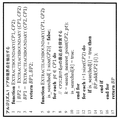
図2は、ドア枠境界点を抽出するための擬似コードのブロック図である。2つの平面の境界点、すなわちCP1及びCP2は、2Dアルファ形状アルゴリズムを用いて別々に抽出される。例えば、Bernardini他「Sampling and Reconstructing Manifolds Using Alpha-Shapes」Purdue e-Pubs, a Serv. Purdue Univ. Libr., pp. 1-11, 1997を参照されたい。 FIG. 2 is a block diagram of pseudo code for extracting door frame boundary points. The boundary points between the two planes, CP1 and CP2, are extracted separately using a 2D alpha shape algorithm. See, for example, Bernardini et al. “Sampling and Reconstructing Manifolds Using Alpha-Shapes” Purdue e-Pubs, a Serv. Purdue Univ. Libr., Pp. 1-11, 1997.
次に、第1の平面において、CP1の各点について、他の平面境界点CP2における最近点が探索される。第1の平面上の全ての点を反復した後、CP2における最近点として探索された点、すなわちBP2が第2の平面上のドア枠境界点である。第2の平面においてこのプロセスを繰り返すことにより、第1の平面上のドア枠境界点、すなわちBP1が得られる。ドア枠境界点BP1及びBP2が検知された後、境界点の2つの集合から2本の線がそれぞれ推定される。距離は、2本の線から推定される。 Next, in the first plane, for each point of CP1, the nearest point at the other plane boundary point CP2 is searched. After repeating all the points on the first plane, the point searched as the closest point in CP2, that is, BP2, is the door frame boundary point on the second plane. By repeating this process in the second plane, a door frame boundary point on the first plane, ie BP1, is obtained. After the door frame boundary points BP1 and BP2 are detected, two lines are estimated from the two sets of boundary points, respectively. The distance is estimated from the two lines.
ユーザーガイダンス
本発明者らによるユーザーガイダンスシステムは、対象となるシーンの事前知識に基づく。ユーザーガイダンスシステムの目的は、シーンから寸法情報を取得するという観点から現在の枠データの品質を示すことである。高品質データは、対象となる基礎構造特性を支持する平面からのデータを十分に含む画像と定義する。
User Guidance The user guidance system by the inventors is based on prior knowledge of the scene in question. The purpose of the user guidance system is to show the quality of the current frame data in terms of obtaining dimensional information from the scene. High quality data is defined as an image that sufficiently contains data from a plane that supports the underlying structural properties of interest.
ユーザーガイダンスシステムは、センサー及びシーンの特徴に基づいて、取得されたデータの品質を評価する。ユーザーガイダンスシステムは、事前情報を十分に活用するように、平面の位相関係を可視化する。箱形状と開口との2つの一般的なケースを示す。 The user guidance system evaluates the quality of the acquired data based on sensor and scene features. The user guidance system visualizes the phase relationship of the plane so that the prior information is fully utilized. Two common cases of box shape and opening are shown.
箱形状
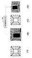
図3(A)は、2つの平行な平面の2つの組を有する形状として定義される箱形状を示す。2つの組は、互いに直角をなす。図3(A)に示すように、平面Aと平面Cとが互いに平行であり、平面Bと平面Dとが互いに平行である。さらに、平面Aは、平面Dに対して直角をなす。実線は、平面間の交線を示す。例として廊下シーンを用いる。
Box Shape FIG. 3A shows a box shape defined as a shape having two sets of two parallel planes. The two sets are at right angles to each other. As shown in FIG. 3A, the plane A and the plane C are parallel to each other, and the plane B and the plane D are parallel to each other. Further, the plane A is perpendicular to the plane D. A solid line indicates a line of intersection between planes. A corridor scene is used as an example.
この構造物の寸法、すなわち廊下の幅及び高さを取得するには、4つの平面全てがセンサーにより取得されなければならない。センサーが4つの平面全てから十分な点を高精度に得ることを確実にするようにユーザーガイダンスが設計される。 To obtain the dimensions of this structure, i.e. the width and height of the hallway, all four planes must be obtained by the sensor. User guidance is designed to ensure that the sensor obtains sufficient points from all four planes with high accuracy.
ユーザーガイダンスは、シーンから少なくとも3つの平面が検知されたと仮定する。この仮定は妥当である。なぜならば、センサーが2つの平面のみを観測した場合、センサーは4つの平面全てを取得することができない場合があるからである。これは、廊下が高すぎてセンサーが4つの平面全てを捕捉することが不可能であるときに発生する。データにおいて1つの平面が取得されない場合、部分データに基づいて幾何解析が行われる。ユーザーを誘導するように、シーンの事前情報及び捕捉されたデータに基づいて、可能性のある形状が再構築される。 User guidance assumes that at least three planes have been detected from the scene. This assumption is valid. This is because if the sensor observes only two planes, the sensor may not be able to acquire all four planes. This occurs when the corridor is too high to allow the sensor to capture all four planes. If one plane is not acquired in the data, a geometric analysis is performed based on the partial data. Potential shapes are reconstructed based on the scene prior information and the captured data to guide the user.
例えば、図3(B)に示すように、平面D、すなわち床がデータから検知されない場合、廊下の高さが不明である。しかしながら、2つの壁に基づいて、廊下の幅を依然として求めることができる。天井及び2つの壁が検知されるので、天井とこれらの壁との間の交線を導出することができる。事前情報及び求められた交線に基づいて、可能性のある高さを推定し、図3(C)に示すような箱形状(白線)を構築することができる。したがって、ユーザーガイダンスシステムは、この状況に対して対応するガイダンスを提供し、図3(D)に示すような床を取得して最終的な寸法を取得するのにより良い姿勢にセンサーを再位置決めする(142)ことができる。 For example, as shown in FIG. 3B, when the plane D, that is, the floor is not detected from the data, the height of the hallway is unknown. However, based on the two walls, the width of the corridor can still be determined. Since the ceiling and two walls are detected, the line of intersection between the ceiling and these walls can be derived. Based on the prior information and the obtained intersection line, a possible height can be estimated, and a box shape (white line) as shown in FIG. 3C can be constructed. Thus, the user guidance system provides corresponding guidance for this situation and repositions the sensor to a better posture to obtain the floor and obtain the final dimensions as shown in FIG. (142).
本方法は、平面Dからは点が存在しないことを検知するので、システムは、平面D、すなわち床から点を取得するように、ユーザーにセンサーを再位置決めすることを提案する。ガイダンスに従うことによって、センサーは下げられるか、又はその向きが下方に傾けられ、次に、画像、すなわち図3(D)が取得される。この画像において、奥行き画像から4つの平面A〜Dのうちの全てを抽出することができ、テンプレートに類似した箱形状が構築される。したがって、幾何解析により廊下の高さ及び幅の双方を求めることができる。 Since the method detects that there are no points from plane D, the system proposes to reposition the sensor to the user to obtain the points from plane D, ie the floor. By following the guidance, the sensor is lowered, or its orientation is tilted downward, and then an image, ie FIG. 3 (D), is acquired. In this image, all of the four planes A to D can be extracted from the depth image, and a box shape similar to the template is constructed. Therefore, both the height and width of the corridor can be obtained by geometric analysis.
ユーザーガイダンスは、欠落した平面を取得するようにセンサーを再位置決めすることのほかに、データ品質に基づいて測定値の品質に関するコメントを提供することもできる。例えば、奥行きセンサーの不確定性は、シーンとセンサーとの間の距離が増加するにしたがって一般的に増加する。したがって、シーン要素がセンサーから離れている場合、このオブジェクトの点は高い不確定性を有し、それによって寸法測定値の正確性が影響される。 In addition to repositioning the sensor to obtain the missing plane, the user guidance can also provide comments on the quality of the measurement based on the data quality. For example, depth sensor uncertainty generally increases as the distance between the scene and the sensor increases. Thus, if the scene element is away from the sensor, the point of this object has a high uncertainty, which affects the accuracy of the dimension measurements.
したがって、データから4つの平面のうちの全てが検知される場合、各平面につき、その重心とセンサーとの間の距離が求められる。センサーまでの距離が閾値よりも大きい、例えば、3.0mである場合、ユーザーガイダンスシステムは、測定の不確定性を最小化するように、その平面にセンサーを近づけるようにユーザーに提案する。 Therefore, when all four planes are detected from the data, the distance between the center of gravity and the sensor is determined for each plane. If the distance to the sensor is greater than a threshold, for example 3.0 m, the user guidance system will suggest to the user to bring the sensor closer to that plane so as to minimize measurement uncertainty.
開口
開口構造物は、第1の平面に対して別の支持平面、例えば床が存在する、平面における開口と定義される。壁における開口であるドア枠を例として用いる。図4(A)〜図4(D)に示すように、平面A及び平面Bは、垂直な壁であり、同じ平面上に存在し、すなわち、これらの壁の関係は同一平面上であり、平面Cは、平面Aと平面Bとに対して直角をなす床である。開口の正確な幅を取得するには、壁の再構築において制約をもたらすのに床が必要である。したがって、床がセンサーにより観測されることを保障するようにユーザーガイダンスが実施される。
Opening An opening structure is defined as an opening in a plane where there is another support plane, for example a floor, relative to the first plane. A door frame, which is an opening in a wall, is used as an example. As shown in FIGS. 4 (A) to 4 (D), the plane A and the plane B are vertical walls and exist on the same plane, that is, the relationship between these walls is on the same plane, The plane C is a floor perpendicular to the plane A and the plane B. In order to obtain the exact width of the opening, a floor is required to constrain the wall reconstruction. Therefore, user guidance is implemented to ensure that the floor is observed by the sensor.
データにおいて平面C、すなわち床が測定されない場合、システムは、図4(B)における2本の実線を依然として再構築することができる。ここで、この2本の実線に基づいて幅が推定される。しかしながら、センサーの奥行き境界周辺の測定値の不正確性に起因して線推定は正確でなく、したがって幅が常に正確とは限らない。ユーザーガイダンスシステムは、図4(A)と図4(C)とを比較することにより、床のデータを取得することができるようにセンサーを下方に再位置決めすることをユーザーに指示する。このようにすることで、図4(D)において、より良い品質データを有する新しい画像が取得される。ドア幅の推定は、線は床に対して垂直であるという制約を加えることにより改良される。 If plane C, the floor, is not measured in the data, the system can still reconstruct the two solid lines in FIG. 4 (B). Here, the width is estimated based on the two solid lines. However, due to the inaccuracy of measurements around the sensor's depth boundary, the line estimate is not accurate, and therefore the width is not always accurate. The user guidance system instructs the user to reposition the sensor downward so that floor data can be acquired by comparing FIG. 4 (A) and FIG. 4 (C). By doing so, a new image having better quality data is acquired in FIG. Door width estimation is improved by adding the constraint that the line is perpendicular to the floor.
加えて、通常ドアは壁に対して窪んでいるので、センサーの視認方向がドアに対して直角をなさない場合、壁がセンサーの視界を遮る可能性がある。したがって、ユーザーガイダンスシステムはこれも考慮する。この評価には、ドア表面の法線ベクトルが用いられる。センサーの視認方向がドア表面に対して垂直でない場合、視認方向はドア表面の法線ベクトルに対して平行ではない。したがって、ユーザーガイダンスシステムは、センサーの視認方向を調整することに関するフィードバックを提供することが可能である。 In addition, since the door is usually recessed with respect to the wall, if the sensor viewing direction is not perpendicular to the door, the wall may block the sensor view. The user guidance system therefore takes this into account. The normal vector of the door surface is used for this evaluation. If the sensor viewing direction is not perpendicular to the door surface, the viewing direction is not parallel to the normal vector of the door surface. Thus, the user guidance system can provide feedback regarding adjusting the viewing direction of the sensor.
Claims (13)
センサーにより取得された前記シーンの単一奥行き画像を取得するステップと、
前記単一奥行き画像から平面を抽出するステップと、
前記平面の位相関係を求めるステップと、
前記平面及び前記位相関係に基づいて前記寸法を求めるステップと、
シーンタイプを用いて、前記単一奥行き画像から取得された前記平面の前記寸法の品質を評価するステップであって、前記品質が十分な場合には前記寸法を出力し、そうでなければ、前記センサーを再位置決めするガイダンスを出力する、ステップと、
を備え、
前記ステップは、プロセッサにおいて行われる
方法。 A method for determining dimensions in a scene,
Obtaining a single depth image of the scene acquired by a sensor;
Extracting a plane from the single depth image;
Obtaining a phase relationship between the planes;
Determining the dimensions based on the plane and the phase relationship;
Using a scene type to evaluate the quality of the dimension of the plane obtained from the single depth image, outputting the dimension if the quality is sufficient, otherwise Outputting guidance for repositioning the sensor, steps;
With
The method is performed in a processor.
請求項1に記載の方法。 The method of claim 1, wherein a red, green, and blue (RGB) image of the scene and the depth image are combined to form an RGB-depth image.
請求項1に記載の方法。 The method of claim 1, wherein the guidance is output to a user.
請求項1に記載の方法。 The method according to claim 1, wherein the guidance is output to a robot on which the sensor is placed.
前記奥行き画像内の画素を群にセグメント化するステップと、
グラフにおいて前記群をノードとして表すステップであって、エッジは、隣接する群を表す、ステップと、
前記グラフに凝集型階層的クラスタリングを適用して、同一平面上のノードを結合するステップと、
を更に備えた請求項1に記載の方法。 The extracting step includes:
Segmenting the pixels in the depth image into groups;
Representing the group as a node in a graph, wherein an edge represents an adjacent group; and
Applying agglomerative hierarchical clustering to the graph to combine nodes on the same plane;
The method of claim 1, further comprising:
2つの平面の法線ベクトルが互いに平行である場合、平行な平面を含み、
2つの平面が同一のパラメーターを有する場合、同一平面上の平面を含み、
2つの平面が平行でない場合、交差する平面を含み、
2つの平面の前記法線ベクトルが互いに直角をなす場合、直角をなす平面を含む
請求項1に記載の方法。 The phase relationship is
If the normal vectors of two planes are parallel to each other, they include parallel planes,
If two planes have the same parameters, include planes on the same plane,
If the two planes are not parallel, include intersecting planes;
The method of claim 1, comprising a plane that is perpendicular if the normal vectors of two planes are perpendicular to each other.
請求項1に記載の方法。 The method of claim 1, further comprising using a least squares procedure to extract the plane.
請求項1に記載の方法。 The method of claim 1, wherein the scene type defines a predetermined shape.
請求項8に記載の方法。 The method according to claim 8, wherein the predetermined shape includes a box shape and an opening shape.
前記2つの組は、互いに直角をなす
請求項9に記載の方法。 The box shape includes two sets of two parallel planes;
The method of claim 9, wherein the two sets are perpendicular to each other.
同一平面上の2つの平面と、
前記同一平面上の2つの平面と直角をなす平面と、
を含む請求項9に記載の方法。 The opening shape is
Two planes on the same plane;
A plane perpendicular to the two planes on the same plane;
The method of claim 9 comprising:
前記方法は、The method
センサーにより取得された前記シーンの単一奥行き画像を取得するステップと、Obtaining a single depth image of the scene acquired by a sensor;
前記単一奥行き画像から平面を抽出するステップと、Extracting a plane from the single depth image;
前記平面の位相関係を求めるステップと、Obtaining a phase relationship between the planes;
前記平面及び前記位相関係に基づいて前記寸法を求めるステップと、Determining the dimensions based on the plane and the phase relationship;
シーンタイプを用いて、前記単一奥行き画像から取得された前記平面の前記寸法の品質を評価するステップであって、前記品質が十分な場合には前記寸法を出力し、そうでなければ、前記センサーを再位置決めするガイダンスを出力する、ステップと、Using a scene type to evaluate the quality of the dimension of the plane obtained from the single depth image, outputting the dimension if the quality is sufficient, otherwise Outputting guidance for repositioning the sensor, steps;
を備えた非一時的コンピューター可読記録媒体。A non-transitory computer-readable recording medium.
前記システムは、前記シーンの単一奥行き画像を取得し、カラー画像とともに前記単一奥行き画像を送信するように構成された奥行きセンサーを備え、The system comprises a depth sensor configured to acquire a single depth image of the scene and transmit the single depth image along with a color image;
前記メモリは、前記プロセッサにシーン内の寸法を求める処理を実行させる方法のステップを記憶するように構成され、The memory is configured to store method steps for causing the processor to perform a process for determining dimensions in a scene;
前記処理は、The process is
センサーにより取得された前記シーンの前記単一奥行き画像を取得するステップと、Acquiring the single depth image of the scene acquired by a sensor;
前記単一奥行き画像から平面を抽出するステップと、Extracting a plane from the single depth image;
前記平面の位相関係を求めるステップと、Obtaining a phase relationship between the planes;
前記平面及び前記位相関係に基づいて前記寸法を求めるステップと、Determining the dimensions based on the plane and the phase relationship;
シーンタイプを用いて、前記単一奥行き画像から取得された前記平面の前記寸法の品質を評価するステップであって、前記品質が十分な場合には前記寸法を出力し、そうでなければ、前記センサーを再位置決めするガイダンスを出力する、ステップと、Using a scene type to evaluate the quality of the dimension of the plane obtained from the single depth image, outputting the dimension if the quality is sufficient, otherwise Outputting guidance for repositioning the sensor, steps;
を備えたシステム。With system.
Applications Claiming Priority (2)
| Application Number | Priority Date | Filing Date | Title |
|---|---|---|---|
| US14/698,200 US9761015B2 (en) | 2015-04-28 | 2015-04-28 | Method for determining dimensions in an indoor scene from a single depth image |
| US14/698,200 | 2015-04-28 |
Publications (3)
| Publication Number | Publication Date |
|---|---|
| JP2016212086A JP2016212086A (en) | 2016-12-15 |
| JP2016212086A5 JP2016212086A5 (en) | 2019-01-24 |
| JP6489552B2 true JP6489552B2 (en) | 2019-03-27 |
Family
ID=57205763
Family Applications (1)
| Application Number | Title | Priority Date | Filing Date |
|---|---|---|---|
| JP2016056626A Active JP6489552B2 (en) | 2015-04-28 | 2016-03-22 | How to find the dimensions in a scene |
Country Status (3)
| Country | Link |
|---|---|
| US (1) | US9761015B2 (en) |
| JP (1) | JP6489552B2 (en) |
| CN (1) | CN106091921B (en) |
Families Citing this family (20)
| Publication number | Priority date | Publication date | Assignee | Title |
|---|---|---|---|---|
| US9858681B2 (en) * | 2014-10-27 | 2018-01-02 | Digimarc Corporation | Signal detection, recognition and tracking with feature vector transforms |
| US9807365B2 (en) * | 2015-12-08 | 2017-10-31 | Mitsubishi Electric Research Laboratories, Inc. | System and method for hybrid simultaneous localization and mapping of 2D and 3D data acquired by sensors from a 3D scene |
| US10721451B2 (en) * | 2016-03-23 | 2020-07-21 | Symbol Technologies, Llc | Arrangement for, and method of, loading freight into a shipping container |
| US10445861B2 (en) * | 2017-02-14 | 2019-10-15 | Qualcomm Incorporated | Refinement of structured light depth maps using RGB color data |
| JP2018156617A (en) * | 2017-03-15 | 2018-10-04 | 株式会社東芝 | Processor and processing system |
| US10803663B2 (en) | 2017-08-02 | 2020-10-13 | Google Llc | Depth sensor aided estimation of virtual reality environment boundaries |
| US10304254B2 (en) * | 2017-08-08 | 2019-05-28 | Smart Picture Technologies, Inc. | Method for measuring and modeling spaces using markerless augmented reality |
| US10733762B2 (en) * | 2018-04-04 | 2020-08-04 | Motorola Mobility Llc | Dynamically calibrating a depth sensor |
| US11270426B2 (en) * | 2018-05-14 | 2022-03-08 | Sri International | Computer aided inspection system and methods |
| CN109000559B (en) * | 2018-06-11 | 2020-09-11 | 广东工业大学 | A method, device, system and readable storage medium for measuring the volume of an object |
| CA3027921C (en) * | 2018-06-25 | 2022-04-12 | Beijing Didi Infinity Technology And Development Co., Ltd. | Integrated sensor calibration in natural scenes |
| CN109682304A (en) * | 2019-02-02 | 2019-04-26 | 北京理工大学 | A kind of composition error modeling method based on CCD camera contraposition assembly system |
| EP3966789A4 (en) | 2019-05-10 | 2022-06-29 | Smart Picture Technologies, Inc. | Methods and systems for measuring and modeling spaces using markerless photo-based augmented reality process |
| CN110853080A (en) * | 2019-09-30 | 2020-02-28 | 广西慧云信息技术有限公司 | Method for measuring size of field fruit |
| CN111412842B (en) * | 2020-04-09 | 2022-02-25 | 广东博智林机器人有限公司 | Method, device and system for measuring section size of wall |
| CN111914901A (en) * | 2020-07-06 | 2020-11-10 | 周爱丽 | Seat arrangement uniformity measuring system and method |
| CN113220018B (en) * | 2021-04-23 | 2023-03-28 | 上海发电设备成套设计研究院有限责任公司 | Unmanned aerial vehicle path planning method and device, storage medium and electronic equipment |
| US11568614B1 (en) | 2021-08-02 | 2023-01-31 | Bank Of America Corporation | Adaptive augmented reality system for dynamic processing of spatial component parameters based on detecting accommodation factors in real time |
| JP7675605B2 (en) * | 2021-09-15 | 2025-05-13 | 株式会社東芝 | Wall detection device, transport vehicle, control method, program, and calculation device |
| US12579753B2 (en) * | 2022-08-15 | 2026-03-17 | Zebra Technologies Corporation | Phased capture assessment and feedback for mobile dimensioning |
Family Cites Families (9)
| Publication number | Priority date | Publication date | Assignee | Title |
|---|---|---|---|---|
| JP3855812B2 (en) * | 2002-03-15 | 2006-12-13 | ソニー株式会社 | Distance measuring method, apparatus thereof, program thereof, recording medium thereof, and robot apparatus mounted with distance measuring apparatus |
| US8655052B2 (en) * | 2007-01-26 | 2014-02-18 | Intellectual Discovery Co., Ltd. | Methodology for 3D scene reconstruction from 2D image sequences |
| JP4535096B2 (en) * | 2007-07-27 | 2010-09-01 | ソニー株式会社 | Planar extraction method, apparatus thereof, program thereof, recording medium thereof, and imaging apparatus |
| US8908913B2 (en) * | 2011-12-19 | 2014-12-09 | Mitsubishi Electric Research Laboratories, Inc. | Voting-based pose estimation for 3D sensors |
| WO2013190772A1 (en) * | 2012-06-20 | 2013-12-27 | パナソニック株式会社 | Spatial information detection device and person location detection device |
| US9230339B2 (en) * | 2013-01-07 | 2016-01-05 | Wexenergy Innovations Llc | System and method of measuring distances related to an object |
| CN103106688B (en) * | 2013-02-20 | 2016-04-27 | 北京工业大学 | Based on the indoor method for reconstructing three-dimensional scene of double-deck method for registering |
| WO2014192316A1 (en) * | 2013-05-31 | 2014-12-04 | パナソニックIpマネジメント株式会社 | Modeling device, three-dimensional model generation device, modeling method, program, and layout simulator |
| JP5799273B2 (en) * | 2013-10-02 | 2015-10-21 | パナソニックIpマネジメント株式会社 | Dimension measuring device, dimension measuring method, dimension measuring system, program |
-
2015
- 2015-04-28 US US14/698,200 patent/US9761015B2/en active Active
-
2016
- 2016-03-22 JP JP2016056626A patent/JP6489552B2/en active Active
- 2016-04-28 CN CN201610273855.0A patent/CN106091921B/en active Active
Also Published As
| Publication number | Publication date |
|---|---|
| US20160321827A1 (en) | 2016-11-03 |
| JP2016212086A (en) | 2016-12-15 |
| CN106091921B (en) | 2019-06-18 |
| CN106091921A (en) | 2016-11-09 |
| US9761015B2 (en) | 2017-09-12 |
Similar Documents
| Publication | Publication Date | Title |
|---|---|---|
| JP6489552B2 (en) | How to find the dimensions in a scene | |
| CN109564690B (en) | Assess the dimensions of enclosed spaces using a multi-directional camera | |
| Hong et al. | Semi-automated approach to indoor mapping for 3D as-built building information modeling | |
| Borrmann et al. | A mobile robot based system for fully automated thermal 3D mapping | |
| US9984177B2 (en) | Modeling device, three-dimensional model generation device, modeling method, program and layout simulator | |
| Braun et al. | A concept for automated construction progress monitoring using bim-based geometric constraints and photogrammetric point clouds. | |
| JP6238183B2 (en) | Modeling device, three-dimensional model generation device, modeling method, program | |
| Fernandez-Moral et al. | Extrinsic calibration of a set of range cameras in 5 seconds without pattern | |
| Ibrahim et al. | Metrics and methods for evaluating model‐driven reality capture plans | |
| Gong et al. | Extrinsic calibration of a 3D LIDAR and a camera using a trihedron | |
| Schaub et al. | Point cloud to BIM registration for robot localization and Augmented Reality | |
| Díaz-Vilariño et al. | Door recognition in cluttered building interiors using imagery and LiDAR data | |
| Braun et al. | Towards automated construction progress monitoring using BIM-based point cloud processing | |
| Gu et al. | Truss member registration for implementing autonomous gripping in biped climbing robots | |
| Muharom et al. | Real-Time 3D Modeling and Visualization Based on RGB-D Camera using RTAB-Map through Loop Closure | |
| Gallegos et al. | Appearance-based slam relying on a hybrid laser/omnidirectional sensor | |
| Shen et al. | Automatic scan planning and construction progress monitoring in unknown building scene | |
| KR20240013706A (en) | A robot capable of measuring its own position and a method of measuring its position in the robot | |
| Zhao et al. | A Building Information Modeling (BIM)-Enabled Robotic System for Automated Indoor Construction Progress Monitoring | |
| Males et al. | Performance Analysis of the Ouster OS1-32 LiDAR sensor for Indoor Mapping | |
| Pargieła et al. | Application of mobile laser scanner to augment stationary collected point clouds | |
| Hu et al. | Image projection onto flat LiDAR point cloud surfaces to create dense and smooth 3D color maps | |
| Reich et al. | On-line compatible orientation of a micro-uav based on image triplets | |
| Lao et al. | Enhanced Extrinsic Calibration Method for Camera-LiDAR Fusion and Monitoring of Safety Threats to Power Transmission Lines | |
| CN118823764B (en) | A method and device for identifying blind spots in power equipment inspection |
Legal Events
| Date | Code | Title | Description |
|---|---|---|---|
| A521 | Request for written amendment filed |
Free format text: JAPANESE INTERMEDIATE CODE: A523 Effective date: 20181206 |
|
| A621 | Written request for application examination |
Free format text: JAPANESE INTERMEDIATE CODE: A621 Effective date: 20181206 |
|
| A871 | Explanation of circumstances concerning accelerated examination |
Free format text: JAPANESE INTERMEDIATE CODE: A871 Effective date: 20181206 |
|
| A975 | Report on accelerated examination |
Free format text: JAPANESE INTERMEDIATE CODE: A971005 Effective date: 20190108 |
|
| TRDD | Decision of grant or rejection written | ||
| A01 | Written decision to grant a patent or to grant a registration (utility model) |
Free format text: JAPANESE INTERMEDIATE CODE: A01 Effective date: 20190122 |
|
| A61 | First payment of annual fees (during grant procedure) |
Free format text: JAPANESE INTERMEDIATE CODE: A61 Effective date: 20190219 |
|
| R150 | Certificate of patent or registration of utility model |
Ref document number: 6489552 Country of ref document: JP Free format text: JAPANESE INTERMEDIATE CODE: R150 |
|
| R250 | Receipt of annual fees |
Free format text: JAPANESE INTERMEDIATE CODE: R250 |
|
| R250 | Receipt of annual fees |
Free format text: JAPANESE INTERMEDIATE CODE: R250 |
|
| R250 | Receipt of annual fees |
Free format text: JAPANESE INTERMEDIATE CODE: R250 |
|
| R250 | Receipt of annual fees |
Free format text: JAPANESE INTERMEDIATE CODE: R250 |
|
| R250 | Receipt of annual fees |
Free format text: JAPANESE INTERMEDIATE CODE: R250 |