JP6487620B2 - Communication control system, communication control method, and program - Google Patents
Communication control system, communication control method, and program Download PDFInfo
- Publication number
- JP6487620B2 JP6487620B2 JP2014004566A JP2014004566A JP6487620B2 JP 6487620 B2 JP6487620 B2 JP 6487620B2 JP 2014004566 A JP2014004566 A JP 2014004566A JP 2014004566 A JP2014004566 A JP 2014004566A JP 6487620 B2 JP6487620 B2 JP 6487620B2
- Authority
- JP
- Japan
- Prior art keywords
- packet
- target system
- address
- router
- target
- Prior art date
- Legal status (The legal status is an assumption and is not a legal conclusion. Google has not performed a legal analysis and makes no representation as to the accuracy of the status listed.)
- Active
Links
Images


Description
本発明は、通信制御システム、通信制御方法、及びプログラムに関する。 The present invention relates to a communication control system, a communication control method, and a program.
従来から、ユーザが操作するユーザ端末と、通信先の対象システムと、の通信を仲介する技術が知られている。特許文献1には、ユーザIDとパスワードをユーザ端末から取得してログイン処理を実行し、ユーザ端末から対象システムへのアクセスを中継する通信制御システムが記載されている。 2. Description of the Related Art Conventionally, a technique for mediating communication between a user terminal operated by a user and a communication target system is known. Patent Document 1 describes a communication control system that acquires a user ID and password from a user terminal, executes login processing, and relays access from the user terminal to a target system.
対象システムの管理者は、その対象システム内でIPアドレスが重複しないように、IPアドレスの設定作業を行っている。しかしながら、互いに管理主体が異なる複数の対象システムが存在する場合には、それぞれの管理者が独自にIPアドレスを付与するので、対象システムどうしでIPアドレスが重複することがある。この場合、通信制御システムがユーザ端末からパケットを受信したとしても、そのパケットを、どの対象システムに送るべきかを特定することができない可能性がある。 The administrator of the target system performs an IP address setting operation so that the IP addresses do not overlap in the target system. However, in the case where there are a plurality of target systems having different management entities, the IP addresses may overlap between the target systems because each administrator assigns an IP address independently. In this case, even if the communication control system receives a packet from the user terminal, it may not be possible to specify to which target system the packet should be sent.
本発明は上記課題に鑑みてなされたものであって、その目的は、対象システムどうしでIPアドレスが重複した場合でも通信を仲介することが可能な通信制御システム、通信制御方法、及びプログラムを提供することにある。 The present invention has been made in view of the above problems, and an object thereof is to provide a communication control system, a communication control method, and a program capable of mediating communication even when IP addresses overlap between target systems. There is to do.
上記課題を解決するために、本発明に係る通信制御システムは、ユーザが操作するユーザ端末と、IPアドレスが重複する組み合わせを含む複数の対象システムと、の通信を仲介する通信制御システムであって、何れか一つの対象システムと通信するルータであって、各対象システムとは異なるネットワーク内に、対象システムごとに用意された複数のルータと、IPアドレスが重複する複数の対象システムの何れかと通信する前記ユーザ端末から受信したパケットを、IPアドレスが重複する当該複数の対象システムのうち、前記ユーザ端末の通信先の対象システムと通信するルータに転送する転送手段と、を含み、前記転送手段が転送したパケットを受信したルータは、そのパケットを、そのルータの通信先の対象システムに転送する、ことを特徴とする。 In order to solve the above problems, a communication control system according to the present invention is a communication control system that mediates communication between a user terminal operated by a user and a plurality of target systems including combinations of overlapping IP addresses. A router that communicates with any one of the target systems, and communicates with a plurality of routers prepared for each target system and any of a plurality of target systems with overlapping IP addresses in a network different from each target system. Forwarding means that forwards a packet received from the user terminal to a router that communicates with a target system of a communication destination of the user terminal among the plurality of target systems having overlapping IP addresses, and the forwarding means The router that has received the forwarded packet forwards the packet to the target system with which the router communicates. And wherein the door.
本発明に係る通信制御方法は、ユーザが操作するユーザ端末と、IPアドレスが重複する組み合わせを含む複数の対象システムと、の通信を仲介する通信制御方法であって、何れか一つの対象システムと通信するルータであって、各対象システムとは異なるネットワーク内に、対象システムごとに用意された複数のルータのうち、IPアドレスが重複する複数の対象システムの何れかと通信する前記ユーザ端末から受信したパケットを、IPアドレスが重複する当該複数の対象システムのうち、前記ユーザ端末の通信先の対象システムと通信するルータに転送する転送ステップと、前記転送ステップにおいて転送されたパケットを受信したルータが、そのパケットを、そのルータの通信先の対象システムに転送するステップと、を含むことを特徴とする。 A communication control method according to the present invention is a communication control method that mediates communication between a user terminal operated by a user and a plurality of target systems including combinations of overlapping IP addresses, and any one of the target systems Receiving from the user terminal that communicates with any of a plurality of target systems having overlapping IP addresses among a plurality of routers prepared for each target system in a network different from each target system. A transfer step of transferring a packet to a router communicating with a target system of a communication destination of the user terminal among the plurality of target systems having overlapping IP addresses, and a router that has received the packet transferred in the transfer step, Forwarding the packet to a target system with which the router communicates. And butterflies.
本発明に係るプログラムは、ユーザが操作するユーザ端末と、IPアドレスが重複する組み合わせを含む複数の対象システムと、の通信を仲介するコンピュータを、何れか一つの対象システムと通信するソフトウェアルータであって、各対象システムとは異なるネットワーク内に、対象システムごとに用意された複数のソフトウェアルータ、IPアドレスが重複する複数の対象システムの何れかと通信する前記ユーザ端末から受信したパケットを、IPアドレスが重複する当該複数の対象システムのうち、前記ユーザ端末の通信先の対象システムと通信するルータに転送する転送手段、として機能させるためのプログラムであって、前記転送手段が転送したパケットを受信したソフトウェアルータは、そのパケットを、そのソフトウェアルータの通信先の対象システムに転送する、ことを特徴とする。 A program according to the present invention is a software router that communicates a computer that mediates communication between a user terminal operated by a user and a plurality of target systems including combinations of overlapping IP addresses with any one target system. Then, in a network different from each target system, a packet received from the user terminal that communicates with a plurality of software routers prepared for each target system or a plurality of target systems with overlapping IP addresses, A program for functioning as a transfer unit that transfers to a router that communicates with a target system that is a communication destination of the user terminal among the plurality of overlapping target systems, the software receiving the packet transferred by the transfer unit The router routes the packet to its software route. To transfer the communication destination of the target system, and wherein the.
また、本発明の一態様では、前記通信制御システムは、各対象システムに対応するIPアドレスであって、他の対象システムとは重複しない管理用IPアドレスと、その対象システムと通信するルータと、の関連付けを記憶する手段の記憶内容を取得する手段を更に含み、前記転送手段は、前記ユーザ端末から受信したパケットを、そのパケットの送信先が示す管理用IPアドレスに関連付けられたルータに転送し、前記転送手段が転送したパケットを受信したルータは、そのパケットの送信先を、その送信先に対応する対象システムのIPアドレスに変換して転送する、ことを特徴とする。 In one aspect of the present invention, the communication control system is an IP address corresponding to each target system, the management IP address not overlapping with another target system, a router communicating with the target system, Means for acquiring the stored contents of the means for storing the association, wherein the transfer means transfers the packet received from the user terminal to the router associated with the management IP address indicated by the transmission destination of the packet. The router that receives the packet transferred by the transfer means converts the transmission destination of the packet into the IP address of the target system corresponding to the transmission destination and transfers the packet.
また、本発明の一態様では、各ルータは、そのルータの通信先の対象システムから受信したパケットの送信元を、その対象システムに対応する管理用IPアドレスに変換し、前記通信制御システムは、前記送信元が変更されたパケットを、前記ユーザ端末に転送する手段、を更に含むことを特徴とする。 In one aspect of the present invention, each router converts a transmission source of a packet received from a target system of a communication destination of the router into a management IP address corresponding to the target system, and the communication control system includes: Means for transferring the packet whose transmission source has been changed to the user terminal;
また、本発明の一態様では、前記通信制御システムは、少なくとも一つの対象システムとIPアドレスが重複し、その対象システムは、IPアドレスを変換するルータを含み、その対象システムと通信する前記通信制御システム内のルータは、前記転送手段が転送したパケットの送信元を、その対象システム内のルータによる変換後のIPアドレスとは異なるIPアドレスに変換して転送する、ことを特徴とする。 In one aspect of the present invention, the communication control system has an IP address overlapping with at least one target system, and the target system includes a router that converts an IP address, and communicates with the target system. The router in the system converts the transmission source of the packet transferred by the transfer means into an IP address different from the IP address after conversion by the router in the target system, and transfers the IP address.
本発明によれば、対象システムどうしでIPアドレスが重複した場合でも通信を仲介することが可能になる。 According to the present invention, it is possible to mediate communication even when IP addresses overlap between target systems.
[1.実施形態1]
以下、本発明の実施形態の例について図面に基づき詳細に説明する。本実施形態では、本発明に係る通信制御システムを、例えば、クラウドコンピューティングを用いた情報処理システムに適用した場合について説明する。
[1. Embodiment 1]
Hereinafter, examples of embodiments of the present invention will be described in detail with reference to the drawings. This embodiment demonstrates the case where the communication control system which concerns on this invention is applied to the information processing system using cloud computing, for example.
[1−1.情報処理システムのハードウェア構成]
図1は、情報処理システムの全体構成の一例を示す図である。図1に示すように、情報処理システム1は、通信制御システム10、複数のユーザ端末20、及び複数の対象システム30(以降、必要に応じて、対象システム30A及び30Bと記載して区別する。)を含む。これらは、ネットワーク(例えば、VPN:Virtual Private Network)を介してデータ送受信可能に接続されている。ユーザ端末20は、通信制御システム10を経由して対象システム30にアクセスすることになり、対象システム30と直接的にアクセスすることができないようになっている。
[1-1. Hardware configuration of information processing system]
FIG. 1 is a diagram illustrating an example of the overall configuration of an information processing system. As shown in FIG. 1, the information processing system 1 distinguishes between the
通信制御システム10は、ユーザ端末20と対象システム30との通信を仲介する。通信制御システム10は、通信制御サーバ11を含む。通信制御サーバ11は、サーバコンピュータであり、例えば、所与のプロトコル(例えば、SSH:Secure ShellやRDP:Remote Desktop Protocol)のもとで各種情報を送受信する。なお、ここでは、説明の簡略化のため、通信制御サーバ11を1台として説明し、その通信制御サーバ11内で、ヴァーチャルマシンやソフトウェアルータが実現される場合を説明するが、通信制御サーバ11は複数台あってもよい。
The
図1に示すように、通信制御サーバ11は、制御部12、記憶部13、及び通信部14を含む。制御部12は、例えば、一又は複数のマイクロプロセッサを含む。制御部12は、記憶部13に記憶されたオペレーティングシステムやプログラムに従って各種処理を実行する。記憶部13は、主記憶部及び補助記憶部を含む。例えば、主記憶部はRAMであり、補助記憶部は、ハードディスク又はソリッドステートドライブ等である。通信部14は、ネットワークカードを含む。通信部14は、ネットワークを介してデータ通信を行うためのものである。
As illustrated in FIG. 1, the
なお、通信制御サーバ11は、コンピュータ読み取り可能な情報記憶媒体(例えば、メモリカード)に記憶されたプログラムやデータを読み出すための構成要素(例えば、メモリカードスロット)を含むようにしてもよい。また、本実施形態において、記憶部13に記憶されるものとして説明するプログラムやデータは、通信部14を介して外部コンピュータから記憶部13に供給されるようにしてもよい。
The
ユーザ端末20は、ユーザが操作するコンピュータであり、例えば、パーソナルコンピュータやタブレット型端末等である。なお、本実施形態では、対象システム30に実行させるコマンドを入力する作業者(例えば、メンテナンスを行う特権ユーザやシステムエンジニア)が、ユーザに相当する。図1に示すように、ユーザ端末20は、制御部21、記憶部22、通信部23、操作部24、及び表示部25を含む。なお、制御部21、記憶部22、及び通信部23のハードウェア構成は、制御部12、記憶部13、及び通信部14と同様であるので説明を省略する。
The
操作部24は、公知の入力デバイスであり、例えば、マウスやキーボード、タッチパネル等である。操作部24は、ユーザによる操作内容を制御部21に伝達する。表示部25は、例えば、液晶表示部又は有機EL表示部等である。表示部25は、制御部21の指示に従って画面を表示する。
The
対象システム30は、ユーザの通信先のシステムである。例えば、各対象システム30は、複数のユーザによるアクセスが可能であり、各ユーザが入力したコマンドを実行する。また、ここでは、各対象システム30の管理主体(例えば、会社)が異なっており、それぞれで独自にIPアドレス(プライベートアドレス)の管理が行われている。このため、IPアドレスが他の対象システム30と重複する対象システム30の組み合わせが存在しているものとする。例えば、会社Aが、対象システム30Aの各装置のIPアドレスを付与し、会社Aとは異なる会社Bが、対象システム30Bの各装置のIPアドレスを付与している。
The target system 30 is a system with which the user communicates. For example, each target system 30 can be accessed by a plurality of users, and executes a command input by each user. Here, the management subject (for example, company) of each target system 30 is different, and the management of the IP address (private address) is performed independently. Therefore, it is assumed that there is a combination of target systems 30 whose IP addresses overlap with other target systems 30. For example, company A gives an IP address of each device of
各対象システム30は、対象サーバ31を含む。対象サーバ31は、サーバコンピュータである。なお、ここでは、説明の簡略化のため、各対象システム30内の対象サーバ31を1台とし、その対象サーバ31内で、ヴァーチャルマシンやソフトウェアルータが実現される場合を説明するが、対象サーバ30は複数台あってもよい。更に、対象システム30には、ルータなどの通信機器やデータベースサーバなどが含まれていてもよい。 Each target system 30 includes a target server 31. The target server 31 is a server computer. Here, for simplification of explanation, a case will be described in which a single target server 31 in each target system 30 is provided and a virtual machine or software router is realized in the target server 31. There may be a plurality of 30 units. Furthermore, the target system 30 may include a communication device such as a router, a database server, and the like.
図1に示すように、対象サーバ31は、制御部32、記憶部33、及び通信部34を含む。制御部32、記憶部33、及び通信部34のハードウェア構成は、制御部12、記憶部13、及び通信部14と略同様であるので説明を省略する。例えば、情報処理システム1の利用者が利用するアプリケーションや各種データは、対象サーバ31の記憶部33で管理される。各利用者は、対象サーバ31にアクセスして、これらアプリケーションや各種データを利用する。
As illustrated in FIG. 1, the target server 31 includes a control unit 32, a storage unit 33, and a communication unit 34. Since the hardware configurations of the control unit 32, the storage unit 33, and the communication unit 34 are substantially the same as those of the
[1−2.情報処理システムにおける処理の概要]
情報処理システム1では、通信制御システム10が、ユーザ端末20と対象システム30との通信を仲介することによって、例えば、ユーザの操作ログを記録するサービスを提供している。以降、ある会社Zが、新たにサービスの利用登録を行う手順に沿って、情報処理システム1が実行する処理の概要を説明する。
[1-2. Outline of processing in information processing system]
In the information processing system 1, the
まず、会社Zは、その会社Zに所属するユーザに関する各種情報(例えば、ユーザの氏名や所属、通信制御システム10へのログインアカウント等)を、通信制御システム10に登録する。そして、通信制御システム10は、各ユーザが通信制御システム10にログインするための認証情報を発行する。認証情報は、プロトコルで規定された認証時に使用する情報であればよく、例えば、認証キー(証明書)やパスワードなどである。
First, the company Z registers various information related to users belonging to the company Z (for example, the user's name and affiliation, a login account to the
そして、会社Zは、自身が管理する対象システム30(即ち、情報処理システム1に新たに追加する対象システム30)に関する情報を、通信制御システム10に登録する。例えば、その対象システム30内の各サーバ名、そのIPアドレス、使用するプロトコルの種別、そのサーバへのログインアカウント、そのサーバへの認証情報などを登録する。認証情報は、上記と同様に、プロトコルで規定された情報(認証キーやパスワード)であればよい。
Then, the company Z registers information related to the target system 30 managed by the company Z (that is, the target system 30 newly added to the information processing system 1) in the
会社Zは、ユーザに関する情報と、対象システム30に関する情報と、を登録すると、これらの紐付け作業を行う。例えば、ユーザごとにアクセス可能なサーバを異ならせる場合には、会社Zは、自身の対象システム30内のサーバのうち、各ユーザがアクセス可能なサーバを指定して、通信制御システム10に登録する。
When the company Z registers information related to the user and information related to the target system 30, the company Z performs these linking operations. For example, when different servers are accessible for each user, the company Z designates a server that can be accessed by each user among the servers in the target system 30 and registers the server in the
その後、会社Zは、通信制御システム10を介して対象システム30にアクセスするためのネットワーク設定を行う。ここでは、通信制御システム10内のネットワーク設定と、対象システム30内のネットワーク設定と、が必要になる。詳細は後述するが、本実施形態では、ソフトウェアルータが用いられるので、通信制御システム10及び対象システム30のそれぞれのソフトウェアルータの設定作業が行われる。例えば、通信制御システム10内のソフトウェアルータと、新たに追加する対象システム30と、の紐付け作業が行われる。なお、通信制御システム10のソフトウェアルータは、予め用意されたものを使用してもよいし、利用登録時に新たに作成するようにしてもよい。
Thereafter, the company Z performs network setting for accessing the target system 30 via the
上記の利用登録が完了すると、会社Zは、サービスを利用できるようになる。ここでは、ユーザが対象システム30にアクセスする場合、そのユーザは、いったん通信制御システム10にログインし、その後、通信制御システム10を介して対象システム30にログインをする。これは、SSHなどの暗号化通信が行われる場合には、ユーザが入力したコマンドやその実行結果も暗号化されているので、プロトコルを通信制御システム10でいったん終了して復号化を行うことで、操作ログを確実に取得するためである。
When the use registration is completed, the company Z can use the service. Here, when a user accesses the target system 30, the user logs in the
本実施形態では、先述のように、IPアドレスが重複する対象システム30の組み合わせが存在するので、通信制御システム10では、対象システム30ごとに専用のソフトウェアルータを用意している。そして、通信制御サーバ11は、各対象システム30内のヴァーチャルマシンごとに、重複しないように管理用IPアドレスを割り当てている。
In the present embodiment, as described above, since there are combinations of target systems 30 with overlapping IP addresses, the
このため、各対象システム30内のヴァーチャルマシンの本当のIPアドレスが重複していたとしても、管理用IPアドレスによって、これらのヴァーチャルマシンを識別できるようになっている。即ち、通信制御システム10は、ユーザ端末20から受け取ったパケットの送信先が示す管理用IPアドレスを参照することで、どの対象システム30のどのヴァーチャルマシン宛てなのかを特定することができる。
For this reason, even if the virtual IP addresses of the virtual machines in each target system 30 are duplicated, these virtual machines can be identified by the management IP address. That is, the
そして、通信制御システム10は、その特定したヴァーチャルマシンを含む対象システム30の通信を担当するソフトウェアルータにパケットを振り分けることで、対象システム30どうしでIPアドレスが重複していても通信を仲介できる構成になっている。以降、当該技術の詳細について説明する。
The
[1−3.情報処理システムにおいて実現される機能]
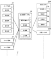
図2は、情報処理システム1で実現される機能を示す機能ブロック図である。ここでは、通信制御システム10及び対象システム30で実現される機能について説明する。なお、図2において、ゲートウェイ110、ソフトウェアルータ120、ヴァーチャルマシン310、及びソフトウェアルータ320の名称の下に記載した数値は、それぞれのIPアドレスである。
[1-3. Functions realized in information processing system]
FIG. 2 is a functional block diagram illustrating functions realized by the information processing system 1. Here, functions realized by the
[対象システムで実現される機能]
各対象システム30では、ヴァーチャルマシン310及びソフトウェアルータ320が実現される。ヴァーチャルマシン310及びソフトウェアルータ320は、一つであってもよいし、複数であってもよい。これらは、制御部32、記憶部33、及び通信部34を主として実現される。
[Functions implemented in the target system]
In each target system 30, a virtual machine 310 and a software router 320 are realized. The number of virtual machines 310 and software routers 320 may be one or plural. These are mainly implemented by the control unit 32, the storage unit 33, and the communication unit 34.
以降、対象システム30ごとにヴァーチャルマシン310を区別する必要があるときは、ヴァーチャルマシン310A及び310Bと記載する。更に、対象システム30内でヴァーチャルマシン310を区別する必要があるときは、ヴャーチャルマシン310A1〜310A3のように記載する。同様に、対象システム30ごとにソフトウェアルータ320や後述のデータ記憶部321を区別する必要があるときは、ソフトウェアルータ320A及び320Bやデータ記憶部321A及び321Bと記載する。
Hereinafter, when it is necessary to distinguish the virtual machine 310 for each target system 30, they are referred to as virtual machines 310A and 310B. Further, when it is necessary to distinguish the virtual machine 310 in the target system 30, it is described as virtual machines 310A1 to 310A3. Similarly, when it is necessary to distinguish the software router 320 and the later-described data storage unit 321 for each target system 30, they are described as
ヴァーチャルマシン310は、仮想的なサーバコンピュータである。別の言い方をすれば、ヴァーチャルマシン310は、ユーザの通信先となる仮想機器であり、ユーザが入力したコマンドを実行する。各ヴァーチャルマシン310には、その対象システム30内で有効なIPアドレス(プライベートアドレス)が割り当てられている。例えば、各ヴァーチャルマシン310のIPアドレスの割り当ては、その対象システム30内の管理者により行われる。このため、図2に示す例では、ヴァーチャルマシン310A1〜310A3の少なくとも一つと、ヴァーチャルマシン310B1〜310B3の少なくとも一つと、はIPアドレスが重複している。 The virtual machine 310 is a virtual server computer. In other words, the virtual machine 310 is a virtual device that is a communication destination of the user, and executes a command input by the user. Each virtual machine 310 is assigned an IP address (private address) that is valid in the target system 30. For example, the IP address of each virtual machine 310 is assigned by an administrator in the target system 30. For this reason, in the example illustrated in FIG. 2, at least one of the virtual machines 310A1 to 310A3 and at least one of the virtual machines 310B1 to 310B3 have overlapping IP addresses.
ソフトウェアルータ320は、仮想的なルータである。ソフトウェアルータ320は、各ヴァーチャルマシン310と通信制御システム10との通信を仲介する。また、ソフトウェアルータ320は、データ記憶部321を含み、そのソフトウェアルータ320の設定情報(例えば、ルーティングテーブル)を記憶する。
The software router 320 is a virtual router. The software router 320 mediates communication between each virtual machine 310 and the
例えば、ソフトウェアルータ320の設定は、対象システム30の管理者により行われる。サービスの利用登録時に、ソフトウェアルータ320には、ゲートウェイ110向けのスタティックルートの設定が追加される。例えば、ゲートウェイ110のIPアドレスが送信先の場合のネクストホップが、そのソフトウェアルータ320のIPアドレスに設定される。図2に示すように、ソフトウェアルータ320AのIPアドレスは、ソフトウェアルータ320BのIPアドレスと重複してもよい。
For example, the setting of the software router 320 is performed by the administrator of the target system 30. At the time of service usage registration, a static route setting for the
なお、ヴァーチャルマシン310やソフトウェアルータ320を実現するための機器仮想化技術自体は、公知の種々の技術を適用可能である。後述のゲートウェイ110やソフトウェアルータ120についても同様である。更に、実施形態1では、対象システム30側のIPアドレス(ヴァーチャルマシン310やソフトウェアルータ320のIPアドレス)は、通信制御システム10側のIPアドレス(ゲートウェイ110やソフトウェアルータ120のIPアドレス)と重複しないようになっている。
Note that various known technologies can be applied to the device virtualization technology itself for realizing the virtual machine 310 and the software router 320. The same applies to the
[通信制御システムで実現される機能]
通信制御システム10では、ゲートウェイ110及び複数のソフトウェアルータ120が実現される。なお、ゲートウェイ110は、複数であってもよい。これらは、制御部12、記憶部13、及び通信部14を主として実現される。以降、必要に応じて、ソフトウェアルータ120A及び120Bやデータ記憶部121A及び121Bと記載して区別する。
[Functions implemented in the communication control system]
In the
ゲートウェイ110は、仮想的なサーバコンピュータである。ゲートウェイ110は、ユーザ端末20から受信したパケットを、何れかのソフトウェアルータ120に転送したり、各ソフトウェアルータ120を介して各対象システム30から受信したパケットをユーザ端末20に転送したりする。また、ゲートウェイ110は、ユーザの操作ログを取得して記録する。
The
本実施形態では、ゲートウェイ110は、データ記憶部111、取得部112、及び転送部113を含む。
In the present embodiment, the
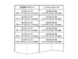
データ記憶部111は、各ソフトウェアルータ120の通信先を識別するデータを記憶する。例えば、データ記憶部111は、各対象システム30に対応するIPアドレスであって、他の対象システム30とは重複しない管理用IPアドレスと、その対象システム30と通信するソフトウェアルータ120と、の関連付けを示すスタティックルートを記憶する。取得部112は、データ記憶部111の記憶内容(ここでは、スタティックルート)を取得する。
The
図3は、スタティックルートの格納例を示す図である。図3に示すように、スタティックルートには、ゲートウェイ110が管理する管理用IPアドレスと、ソフトウェアルータ120を識別する情報(例えば、そのIPアドレス)と、が関連付けられている。
FIG. 3 is a diagram illustrating an example of storing a static route. As shown in FIG. 3, a management route IP address managed by the
管理用IPアドレスは、各対象システム30内のヴァーチャルマシン310を一意に識別するためのプライベートアドレスである。管理用IPアドレスは、対象システム30どうしで重複しないようになっている。別の言い方をすれば、管理用IPアドレスと、各対象システム30内のヴァーチャルマシン310と、は一対一の関係にある。 The management IP address is a private address for uniquely identifying the virtual machine 310 in each target system 30. The management IP address is not duplicated between the target systems 30. In other words, the management IP address and the virtual machine 310 in each target system 30 have a one-to-one relationship.
管理用IPアドレスに関連付けられているソフトウェアルータ120は、その管理用IPアドレスに対応するヴァーチャルマシン310の対象システム30と通信をするソフトウェアルータ120である。別の言い方をすれば、各ソフトウェアルータ120には、その通信先の対象システム30内の各ヴァーチャルマシン310に対応する管理用IPアドレスが関連付けられていることになる。 The software router 120 associated with the management IP address is a software router 120 that communicates with the target system 30 of the virtual machine 310 corresponding to the management IP address. In other words, each software router 120 is associated with a management IP address corresponding to each virtual machine 310 in the communication target system 30.
図3に示すデータ格納例では、ヴァーチャルマシン310A1〜310A3の管理用IPアドレスには、対象システム30Aと通信するソフトウェアルータ120Aが関連付けられている。一方、ヴァーチャルマシン310B1〜310B3の管理用IPアドレスには、対象システム30Bと通信するソフトウェアルータ120Bが関連付けられている。
In the data storage example shown in FIG. 3, the
例えば、スタティックルートは、ヴァーチャルマシン310が新たに追加されると更新される。新たにヴァーチャルマシン310が追加されると、そのヴァーチャルマシンに対応する管理用IPアドレスが発行され、その対象システム30と通信するソフトウェアルータ120に関連付けられる。新たに発行される管理用IPアドレスは、既に発行された管理用IPアドレスとは重複しないようになっている。管理用IPアドレスの設定は、通信制御システム10の管理者により行われるようにしてもよいし、通信制御システム10により自動化されていてもよい。
For example, the static route is updated when a new virtual machine 310 is added. When a new virtual machine 310 is added, a management IP address corresponding to the virtual machine is issued and associated with the software router 120 that communicates with the target system 30. The newly issued management IP address does not overlap with the already issued management IP address. The setting of the management IP address may be performed by an administrator of the
転送部113は、IPアドレスが重複する複数の対象システム30の何れかと通信するユーザ端末20から受信したパケットを、IPアドレスが重複する当該複数の対象システム30のうちユーザ端末20の通信先の対象システム30と通信するソフトウェアルータ120に転送する。転送部113は、ユーザ端末20の通信先の対象システム30を特定し、複数のソフトウェアルータ120のうち、当該特定した対象システム30と通信するソフトウェアルータ120に、ユーザ端末20から受信したパケットを転送する。
The
ここでは、ユーザ端末20が送信するパケットの送信先は、通信先の対象システム30のヴァーチャルマシン310の本当のIPアドレスではなく、そのヴァーチャルマシン310の管理用IPアドレスとなっている。このため、転送部113は、ユーザ端末20から受信したパケットを、そのパケットの送信先が示す管理用IPアドレスに関連付けられたソフトウェアルータ120に転送することになる。転送部113は、スタティックルートを参照することで、パケットの送信先の管理用IPアドレスに対応するヴァーチャルマシン310を特定する。そして、転送部113は、そのヴァーチャルマシン310の対象システム30との通信を行うソフトウェアルータ120にパケットを転送する。
Here, the transmission destination of the packet transmitted by the
各ソフトウェアルータ120は、仮想的なルータである。各ソフトウェアルータ120は、何れか一つの対象システム30と通信する。各ソフトウェアルータ120は、各対象システムとは異なるネットワーク内に、対象システム30ごとに用意されている。即ち、各ソフトウェアルータ120は、対象システム30外にあってネットワークアドレスが異なっている。各ソフトウェアルータ120は、ゲートウェイ110と、自分の通信先の一の対象システム30(例えば、その対象システム30内のソフトウェアルータ320)と、の通信を仲介する。なお、各ソフトウェアルータ120は、IPアドレスが重複しないようになっている。
Each software router 120 is a virtual router. Each software router 120 communicates with any one target system 30. Each software router 120 is prepared for each target system 30 in a network different from each target system. That is, each software router 120 is outside the target system 30 and has a different network address. Each software router 120 mediates communication between the
各ソフトウェアルータ120は、データ記憶部121を含む。データ記憶部121は、ソフトウェアルータ120の設定情報(例えば、ルーティングテーブル)を記憶する。例えば、各ソフトウェアルータ120には、そのソフトウェアルータ120がルーティングを担当する対象システム30が一つとなるように、ルーティングテーブルが定められている。このため、各ソフトウェアルータ120は、複数の対象システム30への通信を行わないようになっている。なお、ソフトウェアルータ120と対象システム30とが、一対一の関係にある場合を説明するが、これらは多対一の関係にあってもよい。 Each software router 120 includes a data storage unit 121. The data storage unit 121 stores setting information (for example, a routing table) of the software router 120. For example, a routing table is defined for each software router 120 so that there is one target system 30 for which the software router 120 is responsible for routing. For this reason, each software router 120 does not communicate with a plurality of target systems 30. In addition, although the case where the software router 120 and the target system 30 are in a one-to-one relationship will be described, these may be in a many-to-one relationship.
転送部113が転送したパケットを受信したソフトウェアルータ120は、そのパケットを、そのソフトウェアルータ120の通信先の対象システム30に転送する。即ち、各ソフトウェアルータ120は、転送部113から受信したパケットを、複数の対象システム30のうち、そのソフトウェアルータ120の通信先の対象システム30に転送する。
The software router 120 that has received the packet transferred by the
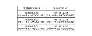
本実施形態では、データ記憶部121は、管理用IPアドレスと、ヴァーチャルマシン310のIPアドレスと、の関係を示すアドレス変換テーブルを記憶する。ここでは、DNAT(Destination Network Address Translation)のルールに従って、アドレス変換がおこなわれるものとする。 In the present embodiment, the data storage unit 121 stores an address conversion table indicating the relationship between the management IP address and the IP address of the virtual machine 310. Here, it is assumed that address translation is performed according to the rules of DNAT (Destination Network Address Translation).
図4は、データ記憶部121Aに記憶されるアドレス変換テーブルの格納例を示す図である。図4に示すように、アドレス変換テーブルには、対象システム30A内のヴァーチャルマシン310A1〜310A3のそれぞれに対応する管理用IPアドレスと、そのヴァーチャルマシン310A1〜310A3の本当のIPアドレス(図4では、「元のIPアドレス」と記載する。)と、が関連付けられている。
FIG. 4 is a diagram illustrating a storage example of the address conversion table stored in the
図5は、データ記憶部121Bに記憶されるアドレス変換テーブルの格納例を示す図である。図5に示すように、アドレス変換テーブルには、対象システム30B内のヴァーチャルマシン310B1〜310B3のそれぞれに対応する管理用IPアドレスと、そのヴァーチャルマシン310B1〜310B3の本当のIPアドレスと、が関連付けられている。図4及び図5に示す例では、ヴァーチャルマシン310A1と、ヴァーチャルマシン310B1と、は本当のIPアドレスが同一であるが、管理用IPアドレスが異なるようになっている。
FIG. 5 is a diagram illustrating a storage example of the address conversion table stored in the
各ソフトウェアルータ120のルーティングテーブルやアドレス変換テーブルは、そのソフトウェアルータ120の通信先の対象システム30に、ヴァーチャルマシン310が新たに追加されると更新される。例えば、新たにヴァーチャルマシン310が追加されると、そのヴァーチャルマシン310に対応する管理用IPアドレスと、その対象システム30のIPアドレスと、の関連付けが、アドレス変換テーブルに追加されることになる。これらの設定は、通信制御システム10の管理者により行われるようにしてもよいし、通信制御システム10により自動化されていてもよい。
The routing table and the address conversion table of each software router 120 are updated when a virtual machine 310 is newly added to the target system 30 with which the software router 120 communicates. For example, when a new virtual machine 310 is added, an association between the management IP address corresponding to the virtual machine 310 and the IP address of the target system 30 is added to the address conversion table. These settings may be performed by an administrator of the
次に、通信制御システム10が対象システム30にパケットを送信して、対象システム30から通信制御システム10にパケットが戻るまでに行われるアドレス変換について説明する。
Next, address conversion that is performed from when the
図6は、パケットが送受信される様子を示す図である。ここでは、ユーザがヴァーチャルマシン310A3にアクセスする場合を例に挙げて説明する。まず、図6に示すように、転送部113が転送するパケットの送信元は、ゲートウェイのIPアドレス「10.200.189.32」であり、送信先は、ヴァーチャルマシン310A3の管理用IPアドレス「10.100.1.5」となる。
FIG. 6 is a diagram illustrating how packets are transmitted and received. Here, a case where the user accesses the virtual machine 310A3 will be described as an example. First, as shown in FIG. 6, the transmission source of the packet transferred by the
転送部113が転送したパケットを受信したソフトウェアルータ120Aは、そのパケットの送信先を、その送信先に対応する対象システム30AのIPアドレスに変換して転送する。図6に示すように、ソフトウェアルータ120Aは、パケットの送信先を、ヴァーチャルマシン310A3の本当のIPアドレス「192.168.1.4」に書き換える。例えば、ソフトウェアルータ120は、アドレス変換テーブルを参照して、受信したパケットの送信先を、その送信先に関連付けられたIPアドレスに書き換えたうえで、そのソフトウェアルータ120の通信先の対象システム30に送信することになる。
Upon receiving the packet transferred by the
そして、ヴァーチャルマシン310A3が送信するパケット(戻りパケット)の送信元は、ヴァーチャルマシン310A3の本当のIPアドレス「192.168.1.4」となり、送信先はゲートウェイのIPアドレス「10.200.189.32」となる。ソフトウェアルータ120Aは、そのソフトウェアルータ120Aの通信先の対象システム30Aから受信したパケットの送信元を、その対象システム30に対応する管理用IPアドレスに変換する。図6に示すように、ソフトウェアルータ120Aは、DNATのルールに従い、パケットの送信元を、ヴァーチャルマシン310A3の管理用IPアドレス「10.100.1.5」に書き換える。例えば、ソフトウェアルータ120は、アドレス変換テーブルを参照して、受信したパケットの送信元を、その送信元に関連付けられた管理用IPアドレスに書き換えたうえで、ゲートウェイ110に転送することになる。
Then, the transmission source of the packet (return packet) transmitted by the virtual machine 310A3 is the real IP address “192.168.1.4” of the virtual machine 310A3, and the transmission destination is the IP address “10.200.189.32” of the gateway. The software router 120 </ b> A converts the transmission source of the packet received from the target system 30 </ b> A that is the communication destination of the software router 120 </ b> A into a management IP address corresponding to the target system 30. As shown in FIG. 6, the
上記のように、各ソフトウェアルータ120では、DNATのルールに従い、対象システム30に送信するパケットの送信先のアドレス変換を行い、対象システム30から戻ってくるパケットの送信元のアドレス変換を行う。 As described above, each software router 120 performs address conversion of a transmission destination of a packet to be transmitted to the target system 30 according to a DNAT rule, and performs address conversion of a transmission source of a packet returned from the target system 30.
なお、各ソフトウェアルータ120がパケットを転送すべきゲートウェイ110を識別する情報(例えば、ゲートウェイ110のIPアドレス)は、そのソフトウェアルータ120のルーティングテーブル等に予め記憶されているものとする。
It is assumed that information (for example, the IP address of the gateway 110) identifying each
ゲートウェイ110の転送部113は、送信元が変更されたパケット(即ち、対象システム30からの戻りパケット)を、ユーザ端末20に転送することになる。このため、ユーザ端末20が受け取るパケットでは、通信相手のヴァーチャルマシン310の本当のIPアドレスではなく、あくまで、管理用IPアドレスに変換されたものとなっている。
The
[1−4.実施形態において実行される処理]
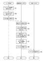
図7及び図8は、情報処理システム1で実行される処理を示す図である。図7及び図8に示す処理が実行されることにより、各機能ブロックが実現される。制御部12,21,32が、それぞれ記憶部13,22,33に記憶されたプログラムに従って動作することにより、下記の処理が実行される。
[1-4. Processing executed in the embodiment]
7 and 8 are diagrams illustrating processing executed in the information processing system 1. Each functional block is realized by executing the processing shown in FIGS. The
なお、下記に説明する処理が実行されるにあたり、通信制御システム10とユーザ端末20との間で第1の通信(例えば、SSH)が確立されており、通信制御システム10と対象システム30との間で第2の通信(例えば、SSH)が確立されているものとする。例えば、ユーザは、通信制御システム10へのログインアカウントと、ユーザ端末20の記憶部22に記憶された認証キーと、を使って通信制御システム10にログインした後に、通信先の対象システム30内のヴャーチャルマシン310へのログインアカウントと、通信制御サーバ11の記憶部12に記憶された認証キーと、を使って、そのヴァーチャルマシン310にログインしているものとする。なお、ログイン時には、ユーザは、通信先のヴァーチャルマシン310の本当のIPアドレスを指定してもよいし、管理用IPアドレスを指定してもよい。
In addition, when the process described below is executed, the first communication (for example, SSH) is established between the
図7に示すように、まず、ユーザ端末20において、制御部21は、コンソール画面を表示部25に表示させる(S1)。図9は、コンソール画面の一例を示す図である。図9に示すように、ここでは、ユーザがすでにヴァーチャルマシン310にログインしており、そのヴァーチャルマシン310に実行させるコマンドの入力が可能な状態となっている。ユーザは、ログイン先のヴァーチャルマシン310に実行させるコマンドを、操作部24を用いてコンソール画面40から入力する。
As shown in FIG. 7, first, in the
制御部21は、ユーザによるコマンドの入力を受け付ける(S2)。制御部21は、ユーザの入力内容を暗号化して通信制御システム10に送信する(S3)。S3においては、制御部21は、ユーザが入力したコマンドやファイル名等の記号列を、記憶部22に記憶された暗号化のための鍵(公開鍵や共通鍵)を用いて暗号化する。そして、制御部21は、接続先のヴァーチャルマシン310の管理用IPアドレスを送信先に設定したパケットに、暗号化した入力内容を格納して送信する。
The
通信制御システム10においては、パケットを受信すると、制御部12は、ゲートウェイ110に、それを復号化させて操作ログを記録させる(S4)。S4においては、制御部12は、記憶部13に記憶された復号化のための鍵(秘密鍵や共通鍵)を用いて、ユーザ端末20から受信したパケットを復号化する。そして、制御部12は、ユーザのログインアカウント、ユーザが入力したコマンドやファイル名等の記号列、通信先のヴァーチャルマシン310の名称やIPアドレス、及び現在の日時に関する情報を、記憶部13に操作ログとして格納する。
In the
なお、操作ログに格納されるヴァーチャルマシン310のIPアドレスは、本当のIPアドレスであってもよいし、管理用IPアドレスであってもよい。また、これらの両方が格納されるようにしてもよい。また、操作ログの確認時には、管理用IPアドレスが、本当のIPアドレスに変換されたうえで表示されるようにしてもよい。 Note that the IP address of the virtual machine 310 stored in the operation log may be a real IP address or a management IP address. Further, both of these may be stored. Further, when the operation log is confirmed, the management IP address may be displayed after being converted into a real IP address.
制御部12は、ゲートウェイ110に、スタティックルートを参照させてパケットを送るべきソフトウェアルータ120を特定させる(S5)。S5においては、制御部12は、受信したパケットの送信先を参照する。そして、制御部12は、その送信先の管理用IPアドレスに関連付けられたソフトウェアルータ120を特定することになる。
The
制御部12は、ゲートウェイ110に、再びパケットの暗号化をさせて、S5で特定したソフトウェアルータ120に送信させる(S6)。S6においては、制御部12は、記憶部13に記憶された暗号化のための鍵(公開鍵や共通鍵)を用いてパケットを暗号化する。なお、ゲートウェイ110と各ソフトウェアルータ120との間は、仮想IP接続されているものとする。
The
制御部12は、S6で送信したパケットを受信したソフトウェアルータ120に、そのパケットのアドレス変換を実行させる(S7)。S7においては、制御部12は、変換テーブルを参照して、パケットの送信先の管理用IPアドレスを、対象サーバ30のヴァーチャルマシン310のIPアドレスに変換する。
The
制御部12は、ソフトウェアルータ120に、S7でアドレス変換したパケットを対象システム30に送信させる(S8)。S8においては、制御部12は、ソフトウェアルータ120の通信先の対象システム30にパケットを送信する。
The
対象システム30においては、パケットを受信すると、制御部32は、ソフトウェアルータ320に転送させる(S9)。S9においては、制御部32は、パケットの送信先のヴァーチャルマシン310に対してパケットを送信する。なお、対象システム30においても、各ヴァーチャルマシン310とソフトウェアルータとの間で仮想IP接続が確立されているものとする。 In the target system 30, when the packet is received, the control unit 32 transfers the packet to the software router 320 (S9). In S9, the control unit 32 transmits the packet to the virtual machine 310 that is the transmission destination of the packet. In the target system 30 as well, it is assumed that a virtual IP connection is established between each virtual machine 310 and the software router.
図8に移り、制御部32は、パケットを受信したヴァーチャルマシン310に、ユーザが入力したコマンドを実行させて、その実行結果を生成させる(S10)。S10においては、制御部32は、記憶部33に記憶された復号化のための鍵(秘密鍵や共通鍵)を用いて、受信したパケットを復号化する。そして、制御部32は、ユーザが入力したコマンドの実行及びその実行結果の生成を行うことになる。 Moving to FIG. 8, the control unit 32 causes the virtual machine 310 that has received the packet to execute the command input by the user and generate the execution result (S <b> 10). In S10, the control unit 32 decrypts the received packet using the decryption key (secret key or common key) stored in the storage unit 33. Then, the control unit 32 executes the command input by the user and generates the execution result.
制御部32は、コマンドを実行したヴァーチャルマシン310に、S10で生成した実行結果を暗号化させ、ソフトウェアルータ320を介して通信制御システム10に送信させる(S11)。制御部32は、記憶部33に記憶された暗号化のための鍵(公開鍵や共通鍵)を用いてパケットを暗号化する。そして、制御部32は、そのパケットの送信元を、ヴァーチャルマシン310のIPアドレスに設定して、ソフトウェアルータ320を介して通信制御システム10に送信する。
The control unit 32 causes the virtual machine 310 that executed the command to encrypt the execution result generated in S10 and transmits the result to the
通信制御システム10においては、パケットを受信すると、制御部12は、ソフトウェアルータ120に、アドレス変換を実行させる(S12)。S12においては、制御部12は、アドレス変換テーブルを参照して、受信したパケットの送信元を、ヴァーチャルマシン310の本当のIPアドレスから、管理用IPアドレスに変換する。
In the
制御部12は、ソフトウェアルータ120に、S12でアドレスを変換したパケットをゲートウェイ110に転送させる(S13)。なお、ゲートウェイ110のIPアドレスは、予め記憶部13に記憶されており、ソフトウェアルータ120はそのIPアドレスを特定可能になっている。
The
制御部12は、ゲートウェイ110に、受信したパケットの復号化をさせて、操作ログを記録させる(S14)。S14においては、制御部12は、記憶部13に記憶された復号化のための鍵(秘密鍵や共通鍵)を用いて、ソフトウェアルータ120から受信したパケットを復号化し、コマンドの実行結果を操作ログとして記憶部13に記録する。
The
制御部12は、ゲートウェイ110に、パケットを暗号化させてユーザ端末20に送信させる(S15)。S15においては、制御部12は、記憶部13に記憶された暗号化のための鍵(公開鍵や共通鍵)を用いて、コマンドの実行結果を暗号化して送信する。
The
ユーザ端末20においては、コマンドの実行結果を受信すると、制御部21は、それを復号化して、コンソール画面40に表示させ(S16)、S2の処理に戻る。S16においては、制御部21は、記憶部22に記憶された復号化のための鍵(秘密鍵や共通鍵)を用いて、コマンドの実行結果を復号化する。以降、ユーザがログアウトするまでS2〜S16の処理が繰り返される。
In the
以上説明した情報処理システム1によれば、対象システム30ごとにソフトウェアルータ120を用意しておき、ユーザ端末20から受信したパケットを、ゲートウェイ110に振り分けさせることで、対象システム30どうしでIPアドレスが重複していたとしても、通信を仲介することが可能になる。
According to the information processing system 1 described above, the software router 120 is prepared for each target system 30, and the packets received from the
また、通信制御システム10では、ヴァーチャルマシン310どうしで重複しないように管理用IPアドレスが管理されているので、本当のIPアドレスが重複していたとしても、管理用IPアドレスによって、どのヴァーチャルマシン310宛てのパケットなのかを特定することができる。更に、ソフトウェアルータ120に、管理用IPアドレスを本当のIPアドレスに変換させることで、正確にルーティングを行うことができる。この点、IPアドレスの変換を通信制御システム10が行うので、対象システム30側(即ち、サービスを受ける顧客側)の改修をする必要がないため、ユーザの利便性が向上する。
In the
また例えば、プロキシを使用すれば通信の振り分けを行うことが一応は可能であるが、実施形態で説明した手法によれば、プロキシに対応していないプロトコル(例えば、RDP)であっても、ゲートウェイ110がパケットを振り分けることで通信の仲介が可能になる。即ち、ユーザが使用するプロトコルに依存せず、通信の仲介が可能になるため、ユーザの利便性が向上する。
Further, for example, if a proxy is used, it is possible to sort communication, but according to the method described in the embodiment, even if the protocol does not support the proxy (for example, RDP), the
また、各ソフトウェアルータ120が対象システム30から受信したパケットの送信先を管理用IPアドレスに書き換えたうえでユーザ端末20に転送されるので、ユーザ端末20は、自分の通信先のヴァーチャルマシン310の管理用IPアドレスを知ることができ、その管理用IPアドレスを送信先にしてパケットを送信すれば、ヴァーチャルマシン310にパケットを送り届けることができる。
In addition, since each software router 120 rewrites the transmission destination of the packet received from the target system 30 to the management IP address and forwards it to the
[2.実施形態2]
次に、情報処理システム1の別実施形態について説明する。実施形態1では、対象システム30どうしのIPアドレスが重複している場合の通信制御について説明したが、実施形態2では、通信制御システム10と対象システム30の間でIPアドレスが重複する場合の通信制御について説明する。なお、ハードウェア構成は、実施形態2と同様であるため、説明を省略する。また、他の箇所についても、実施形態1と同様の部分については説明を省略する。
[2. Second Embodiment]
Next, another embodiment of the information processing system 1 will be described. In the first embodiment, the communication control when the IP addresses of the target systems 30 are duplicated has been described. In the second embodiment, the communication when the IP addresses are duplicated between the
実施形態2では、通信制御システム10は、少なくとも一つの対象システム30とIPアドレスが重複している。また、ソフトウェアルータ120及びソフトウェアルータ320は、ともに、DNAT及びSNAT(Source NAT)の機能を有する。
In the second embodiment, the
図10は、実施形態2において実現される機能を説明するための図である。ここでは、ゲートウェイ110のIPアドレスと、ヴァーチャルマシン310A3のIPアドレスと、が重複している場合を説明する。図10に示すように、ゲートウェイ110から送信されたパケットの送信元は、ゲートウェイ110のIPアドレス「10.200.189.32」であり、送信先は、ヴァーチャルマシン310A3の管理用IPアドレス「10.100.1.5」となる。
FIG. 10 is a diagram for explaining functions realized in the second embodiment. Here, a case will be described in which the IP address of the
ソフトウェアルータ120Aは、パケットの送信元を、ゲートウェイ110の本当のIPアドレス「10.200.189.32」から仮のIPアドレス「172.16.1.1」に変換し、送信先を、ヴァーチャルマシン310A3の管理用IPアドレス「10.100.1.5」から仮のIPアドレス「192.168.1.4」に変換する。即ち、ソフトウェアルータ120Aは、転送部113が転送したパケットの送信元を、対象システム30のソフトウェアルータ320Aによる変換後のIPアドレスとは異なるIPアドレスに変換して転送することで、ゲートウェイ110及びヴァーチャルマシン310A3は、仮のIPアドレスが重複しないようになっている。
The
ソフトウェアルータ320Aは、パケットの送信先を、ヴァーチャルマシン310A3の仮のIPアドレス「192.168.1.4」から、本当のIPアドレス「10.200.189.32」に変換する。このため、パケットをヴァーチャルマシン310A3に届けることができる。
The
一方、対象システム30から通信制御システム10に戻るパケットの送信元は、ヴァーチャルマシン310A3の本当のIPアドレス「10.200.189.32」が設定され、送信先は、ゲートウェイ110の仮のIPアドレス「172.16.1.1」が設定される。ソフトウェアルータ320Aは、パケットの送信元を、ヴァーチャルマシン310A3の本当のIPアドレス「10.200.189.32」から仮のIPアドレス「192.168.1.4」に変換する。
On the other hand, the transmission source of the packet returning from the target system 30 to the
ソフトウェアルータ120Aは、受信したパケットの送信元をヴァーチャルマシン310A3の仮のIPアドレス「192.168.1.4」から管理用IPアドレス「10.100.1.5」に変換し、送信先を、ゲートウェイ110の仮のIPアドレス「172.16.1.1」から本当のIPアドレス「10.200.189.32」に変換する。このため、ゲートウェイ110とヴァーチャルマシン310A3とでIPアドレスが重複していても、パケットをユーザ端末20まで届けることができる。
Software router 1 20A converts the transmission source of the received packet to the IP address "10.100.1.5" for managing the IP address "192.168.1.4" of the temporary virtual machine 310A3, the destination, the
なお、上記では、ゲートウェイ110とヴァーチャルマシン310A3とのIPアドレスが重複する場合を例に挙げて説明したが、他のヴァーチャルマシン310のIPアドレスと重複する場合も同様に、ソフトウェアルータ120及び320で2回のアドレス変換を行うことで、通信が可能になる。即ち、通信制御システム10のIPアドレスを仮のIPアドレスに変換し、当該仮のIPアドレスとは異なるように、対象システム30のIPアドレスを仮のIPアドレスに変換するようにすればよい。また、実施形態1の技術と組み合わせた場合を説明したが、対象システム30どうしのIPアドレスが重複していない場合には、管理用IPアドレスの変換は行われないようにしてもよい。
In the above description, the case where the IP addresses of the
実施形態2の通信制御システム10によれば、通信制御システム10と対象システム30の間でIPアドレスが重複したとしても、2回のアドレス変換を行うことによって通信をすることが可能になる。
According to the
[3.変形例]
なお、本発明は、以上に説明した実施の形態に限定されるものではない。本発明の趣旨を逸脱しない範囲で、適宜変更可能である。
[3. Modified example]
The present invention is not limited to the embodiment described above. Modifications can be made as appropriate without departing from the spirit of the present invention.
例えば、転送部113が、ユーザ端末20から受信したパケットを転送すべきソフトウェアルータ120を特定する方法は、上記の例に限られない。転送部113は、受信したパケットがどの対象システム30向けなのかを、予め定められた方法に基づいて特定すればよい。
For example, the method by which the
例えば、ユーザがログインできる対象システム30が限られている場合には、転送部113は、ユーザがログイン可能な対象システム30を特定し、ユーザ端末20から受信したパケットを、その対象システム30との通信を担当するソフトウェアルータ120に転送するようにしてもよい。この場合、データ記憶部111には、各ユーザがアクセス可能な対象システム30を定義したデータが記憶されており、転送部113は、そのデータを参照することで、ユーザがアクセス可能な対象システム30を特定することになる。
For example, when the target system 30 to which the user can log in is limited, the
また例えば、転送部113は、ユーザ端末20のIPアドレスに基づいて、通信先の対象システム30を特定するようにしてもよい。例えば、対象システム30ごとに、その対象システム30と通信できるユーザ端末20のIPアドレスが定められている場合には、転送部113は、パケットの送信元のIPアドレスでアクセス可能な対象システム30を特定し、その対象システム30との通信を担当するソフトウェアルータ120に転送するようにしてもよい。この場合、データ記憶部111には、各ユーザ端末20のIPアドレスでアクセス可能な対象システム30を定義したデータが記憶されており、転送部113は、そのデータを参照することで、ユーザのIPアドレスがアクセス可能な対象システム30を特定することになる。
Further, for example, the
また例えば、ゲートウェイ110及び各ソフトウェアルータ120にプライベートアドレスが割り当てられる場合を説明するが、これらには、グローバルアドレスが割り当てられていてもよい。
For example, although the case where a private address is allocated to the
また例えば、上記実施形態では、ゲートウェイ110、ソフトウェアルータ120、ヴァーチャルマシン310、及びソフトウェアルータ320を例に挙げて説明したが、これらは、仮想機器ではなく、それぞれ実在するゲートウェイサーバ、ルータ、及びサーバコンピュータであってもよい。また例えば、サーバコンピュータがユーザのコマンドを実行する場合を説明したが、ユーザのコマンドを実行するのは、例えば、対象システム30内のネットワーク機器であってもよい。
Further, for example, in the above-described embodiment, the
また例えば、通信プロトコルの一例としてSSHやRDPを説明したが、他の種々のプロトコルによる通信が適用可能である。例えば、TELNET、FTP、SCP、SFTP、HTTP、又はHTTPSにより通信が行われるようにしてもよい。また例えば、上記においては、本発明に関る通信制御システムを、クラウドコンピューティングを利用した情報処理システムに適用する例を説明したが、本発明に関る通信制御サーバは、ユーザがサーバにリモートアクセスする種々のシステムに適用可能である。 For example, although SSH and RDP have been described as examples of communication protocols, communication using various other protocols can be applied. For example, communication may be performed by TELNET, FTP, SCP, SFTP, HTTP, or HTTPS. Further, for example, in the above description, the communication control system according to the present invention is applied to an information processing system using cloud computing. Applicable to various accessing systems.
1 情報処理システム、10 通信制御システム、11 通信制御サーバ、12,21,32 制御部、13,22,33 記憶部、14,23,34 通信部、20 ユーザ端末、24 操作部、25 表示部、30,30A,30B 対象システム、31 対象サーバ、40 コンソール画面、110 ゲートウェイ、111,111A,111B,121,121A,121B,321,321A,321B データ記憶部、112 取得部、113 転送部、120,120A,120B,320,321A,321B ソフトウェアルータ、310,310A1,310A2,310A3,310B1,310B2,310B3 ヴァーチャルマシン。 DESCRIPTION OF SYMBOLS 1 Information processing system, 10 Communication control system, 11 Communication control server, 12, 21, 32 Control part, 13, 22, 33 Storage part, 14, 23, 34 Communication part, 20 User terminal, 24 Operation part, 25 Display part , 30, 30A, 30B target system, 31 target server, 40 console screen, 110 gateway, 111, 111A, 111B, 121, 121A, 121B, 321, 321A, 321B data storage unit, 112 acquisition unit, 113 transfer unit, 120 120A, 120B, 320, 321A, 321B software router, 310, 310A1, 310A2, 310A3, 310B1, 310B2, 310B3 virtual machine.
Claims (5)
前記ユーザを前記通信制御システムにログインさせる手段と、
前記通信制御システムにログインした前記ユーザを、前記複数の対象システムの何れかにログインさせる手段と、
何れか一つの対象システムと通信するルータであって、各対象システムとは異なるネットワーク内に、対象システムごとに用意された複数のルータと、
各対象システムに対応するIPアドレスであって、他の対象システムとは重複しない管理用IPアドレスと、その対象システムと通信するルータと、の関連付けを記憶する手段の記憶内容を取得する手段と、
IPアドレスが重複し、それぞれへの経路が同時に使用可能な前記複数の対象システムのうち、前記ユーザがログインした対象システムと通信する前記ユーザ端末から受信した暗号化されたパケットを復号化して操作ログを記録し、そのパケットを再び暗号化してそのパケットの送信先が示す管理用IPアドレスに関連付けられたルータに転送する転送手段と、
を含み、
前記転送手段が転送したパケットを受信したルータは、そのパケットの送信先を、そのルータの通信先の対象システムのIPアドレスに変換して転送する、
ことを特徴とする通信制御システム。 And a user terminal operated by a user, the communication control system to mediate a target system a plurality of paths are available simultaneously to each combination a including a plurality of systems which each other's IP addresses overlap, communication of There,
Means for logging the user into the communication control system;
Means for logging in the user who has logged into the communication control system into any of the plurality of target systems;
A router that communicates with any one of the target systems, and a plurality of routers prepared for each target system in a network different from each target system;
An IP address corresponding to each target system, a management IP address that does not overlap with another target system, and a means for acquiring storage contents of a means for storing an association between the router communicating with the target system;
An operation log obtained by decrypting an encrypted packet received from the user terminal that communicates with the target system to which the user has logged in among the plurality of target systems that have overlapping IP addresses and that can simultaneously use routes to each other. recording a transfer means for transferring to the router associated with the packet again encrypted management IP address indicated by the destination of the packet,
Including
The router that has received the packet transferred by the transfer means converts the transmission destination of the packet into the IP address of the target system of the communication destination of the router, and transfers the packet.
A communication control system characterized by that.
前記通信制御システムは、
前記送信元が変更されたパケットを、前記ユーザ端末に転送する手段、
を更に含むことを特徴とする請求項1に記載の通信制御システム。 Each router converts the transmission source of the packet received from the target system of the communication destination of the router into a management IP address corresponding to the target system,
The communication control system includes:
Means for transferring the packet whose source has been changed to the user terminal;
The communication control system according to claim 1, further comprising:
その対象システムは、IPアドレスを変換するルータを含み、
その対象システムと通信する前記通信制御システム内のルータは、前記転送手段が転送したパケットの送信元を、その対象システム内のルータによる変換後のIPアドレスとは異なるIPアドレスに変換して転送する、
ことを特徴とする請求項1又は2に記載の通信制御システム。 The communication control system has an IP address overlapping with at least one target system,
The target system includes a router that translates an IP address,
The router in the communication control system that communicates with the target system converts the source of the packet transferred by the transfer means to an IP address different from the IP address after conversion by the router in the target system and transfers the packet. ,
The communication control system according to claim 1 or 2.
前記ユーザを前記通信制御システムにログインさせるステップと、
前記通信制御システムにログインした前記ユーザを、前記複数の対象システムの何れかにログインさせるステップと、
各対象システムに対応するIPアドレスであって、他の対象システムとは重複しない管理用IPアドレスと、その対象システムとは異なるネットワーク内に用意された、その対象システムと通信するルータと、の関連付けを記憶する手段の記憶内容を取得するステップと、
IPアドレスが重複し、それぞれへの経路が同時に使用可能な前記複数の対象システムのうち、前記ユーザがログインした対象システムと通信する前記ユーザ端末から受信した暗号化されたパケットを復号化して操作ログを記録し、そのパケットを再び暗号化してそのパケットの送信先が示す管理用IPアドレスに関連付けられたルータに転送する転送ステップと、
を含み、
前記転送ステップにおいて転送されたパケットを受信したルータが、そのパケットの送信先を、そのルータの通信先の対象システムのIPアドレスに変換して転送するステップと、
を含むことを特徴とする通信制御方法。 And a user terminal operated by a user, the communication control system to mediate a target system a plurality of paths are available simultaneously to each combination a including a plurality of systems which each other's IP addresses overlap, communication of A communication control method,
Logging the user into the communication control system;
Logging the user logged into the communication control system into any of the plurality of target systems;
Association between a management IP address corresponding to each target system and not overlapping with another target system, and a router that is prepared in a network different from the target system and communicates with the target system Obtaining the stored contents of the means for storing
An operation log obtained by decrypting an encrypted packet received from the user terminal that communicates with the target system to which the user has logged in among the plurality of target systems that have overlapping IP addresses and that can simultaneously use routes to each other. record and a transfer step of the packet again encrypted transferred to a router associated with the management IP address indicated by the destination of the packet,
Including
The router that has received the packet transferred in the transfer step converts the destination of the packet into the IP address of the target system of the communication destination of the router, and transfers the packet.
The communication control method characterized by including.
前記ユーザを前記コンピュータにログインさせる手段、
前記コンピュータにログインした前記ユーザを、前記複数の対象システムの何れかにログインさせる手段、
何れか一つの対象システムと通信するソフトウェアルータであって、各対象システムとは異なるネットワーク内に、対象システムごとに用意された複数のソフトウェアルータ、
各対象システムに対応するIPアドレスであって、他の対象システムとは重複しない管理用IPアドレスと、その対象システムと通信するルータと、の関連付けを記憶する手段の記憶内容を取得する手段、
IPアドレスが重複し、それぞれへの経路が同時に使用可能な前記複数の対象システムの何れかと通信する前記ユーザ端末から受信したパケットを、そのパケットの送信先が示す管理用IPアドレスに関連付けられたルータに転送する転送手段、
IPアドレスが重複し、それぞれへの経路が同時に使用可能な前記複数の対象システムのうち、前記ユーザがログインした対象システムと通信する前記ユーザ端末から受信した暗号化されたパケットを復号化して操作ログを記録し、そのパケットを再び暗号化してそのパケットの送信先が示す管理用IPアドレスに関連付けられたルータに転送する転送手段、
として機能させるためのプログラムであって、
前記転送手段が転送したパケットを受信したルータは、そのパケットの送信先を、そのルータの通信先の対象システムのIPアドレスに変換して転送する、
ことを特徴とするプログラム。 And a user terminal operated by a user, a target system a plurality of paths are available simultaneously to each combination a including a plurality of systems which each other's IP address is duplicated, the computer that mediates communication,
Means for logging the user into the computer;
Means for logging in the user logged into the computer into any of the plurality of target systems;
A software router that communicates with any one target system, and a plurality of software routers prepared for each target system in a network different from each target system,
Means for acquiring storage contents of a means for storing an association between a management IP address corresponding to each target system and not overlapping with other target systems and a router communicating with the target system;
A router associated with a management IP address indicated by a transmission destination of a packet received from the user terminal that communicates with any of the plurality of target systems that have overlapping IP addresses and routes that can be simultaneously used Transfer means to transfer to,
An operation log obtained by decrypting an encrypted packet received from the user terminal that communicates with the target system to which the user has logged in among the plurality of target systems that have overlapping IP addresses and that can simultaneously use routes to each other. A transfer unit that records the packet , re-encrypts the packet, and forwards the packet to the router associated with the management IP address indicated by the transmission destination of the packet ;
Is a program for functioning as
The router that has received the packet transferred by the transfer means converts the transmission destination of the packet into the IP address of the target system of the communication destination of the router, and transfers the packet.
A program characterized by that.
Priority Applications (1)
| Application Number | Priority Date | Filing Date | Title |
|---|---|---|---|
| JP2014004566A JP6487620B2 (en) | 2014-01-14 | 2014-01-14 | Communication control system, communication control method, and program |
Applications Claiming Priority (1)
| Application Number | Priority Date | Filing Date | Title |
|---|---|---|---|
| JP2014004566A JP6487620B2 (en) | 2014-01-14 | 2014-01-14 | Communication control system, communication control method, and program |
Publications (3)
| Publication Number | Publication Date |
|---|---|
| JP2015133639A JP2015133639A (en) | 2015-07-23 |
| JP2015133639A5 JP2015133639A5 (en) | 2017-02-23 |
| JP6487620B2 true JP6487620B2 (en) | 2019-03-20 |
Family
ID=53900539
Family Applications (1)
| Application Number | Title | Priority Date | Filing Date |
|---|---|---|---|
| JP2014004566A Active JP6487620B2 (en) | 2014-01-14 | 2014-01-14 | Communication control system, communication control method, and program |
Country Status (1)
| Country | Link |
|---|---|
| JP (1) | JP6487620B2 (en) |
Families Citing this family (1)
| Publication number | Priority date | Publication date | Assignee | Title |
|---|---|---|---|---|
| JP6852495B2 (en) | 2017-03-23 | 2021-03-31 | 富士通株式会社 | Address translation device, information processing system, and control method of information processing system |
Family Cites Families (2)
| Publication number | Priority date | Publication date | Assignee | Title |
|---|---|---|---|---|
| JP5486526B2 (en) * | 2011-02-17 | 2014-05-07 | 日本電信電話株式会社 | Control device, control system, control method, and control program |
| JP5552460B2 (en) * | 2011-04-13 | 2014-07-16 | 日本電信電話株式会社 | Inter-base connection system, inter-base connection method, address conversion information generation apparatus, address conversion information generation method, and program |
-
2014
- 2014-01-14 JP JP2014004566A patent/JP6487620B2/en active Active
Also Published As
| Publication number | Publication date |
|---|---|
| JP2015133639A (en) | 2015-07-23 |
Similar Documents
| Publication | Publication Date | Title |
|---|---|---|
| US11799831B2 (en) | Intelligent service layer for separating application from physical networks and extending service layer intelligence over IP across the internet, cloud, and edge networks | |
| US10362032B2 (en) | Providing devices as a service | |
| JP2023036622A (en) | Extension of network control system into public cloud | |
| US20130204971A1 (en) | Providing access to configurable private computer networks | |
| US10187356B2 (en) | Connectivity between cloud-hosted systems and on-premises enterprise resources | |
| EP2681874B1 (en) | Ipsec connection to private networks | |
| US11233863B2 (en) | Proxy application supporting multiple collaboration channels | |
| JP2013105308A (en) | Load distribution system, load distribution device, load distribution method and load distribution program | |
| CN110537354B (en) | System and method for configuring virtual private gateway | |
| WO2014148483A1 (en) | Dns server device, network machine, communication system, and communication method | |
| JP6487620B2 (en) | Communication control system, communication control method, and program | |
| US20230179582A1 (en) | Centralized management of private networks | |
| JP6890674B2 (en) | Information processing device and information processing method | |
| Sangha et al. | VMware NSX Cookbook: Over 70 recipes to master the network virtualization skills to implement, validate, operate, upgrade, and automate VMware NSX for vSphere | |
| US11343079B2 (en) | Secure application deployment | |
| US11695773B2 (en) | Distributing dynamic access control lists for managing interactions with a cloud datacenter | |
| US20240137339A1 (en) | Intelligent service layer for separating application from physical networks and extending service layer intelligence over ip across the internet, cloud, and edge networks | |
| Ngekeh | CONFIGURING AND USING OPEN VPN ON WINDOWS OS |
Legal Events
| Date | Code | Title | Description |
|---|---|---|---|
| A521 | Request for written amendment filed |
Free format text: JAPANESE INTERMEDIATE CODE: A523 Effective date: 20170113 |
|
| A625 | Written request for application examination (by other person) |
Free format text: JAPANESE INTERMEDIATE CODE: A625 Effective date: 20170113 |
|
| A711 | Notification of change in applicant |
Free format text: JAPANESE INTERMEDIATE CODE: A711 Effective date: 20170330 |
|
| A521 | Request for written amendment filed |
Free format text: JAPANESE INTERMEDIATE CODE: A821 Effective date: 20170330 |
|
| A131 | Notification of reasons for refusal |
Free format text: JAPANESE INTERMEDIATE CODE: A131 Effective date: 20170829 |
|
| A521 | Request for written amendment filed |
Free format text: JAPANESE INTERMEDIATE CODE: A523 Effective date: 20171023 |
|
| A131 | Notification of reasons for refusal |
Free format text: JAPANESE INTERMEDIATE CODE: A131 Effective date: 20180313 |
|
| A521 | Request for written amendment filed |
Free format text: JAPANESE INTERMEDIATE CODE: A523 Effective date: 20180426 |
|
| A02 | Decision of refusal |
Free format text: JAPANESE INTERMEDIATE CODE: A02 Effective date: 20180911 |
|
| A521 | Request for written amendment filed |
Free format text: JAPANESE INTERMEDIATE CODE: A523 Effective date: 20181207 |
|
| A911 | Transfer to examiner for re-examination before appeal (zenchi) |
Free format text: JAPANESE INTERMEDIATE CODE: A911 Effective date: 20181213 |
|
| TRDD | Decision of grant or rejection written | ||
| A01 | Written decision to grant a patent or to grant a registration (utility model) |
Free format text: JAPANESE INTERMEDIATE CODE: A01 Effective date: 20190219 |
|
| A61 | First payment of annual fees (during grant procedure) |
Free format text: JAPANESE INTERMEDIATE CODE: A61 Effective date: 20190222 |
|
| R150 | Certificate of patent or registration of utility model |
Ref document number: 6487620 Country of ref document: JP Free format text: JAPANESE INTERMEDIATE CODE: R150 |
|
| S533 | Written request for registration of change of name |
Free format text: JAPANESE INTERMEDIATE CODE: R313533 |
|
| R350 | Written notification of registration of transfer |
Free format text: JAPANESE INTERMEDIATE CODE: R350 |
|
| R250 | Receipt of annual fees |
Free format text: JAPANESE INTERMEDIATE CODE: R250 |
|
| R250 | Receipt of annual fees |
Free format text: JAPANESE INTERMEDIATE CODE: R250 |