JP6485488B2 - interchangeable lens - Google Patents

interchangeable lens Download PDF

Info

Publication number
JP6485488B2
JP6485488B2 JP2017099025A JP2017099025A JP6485488B2 JP 6485488 B2 JP6485488 B2 JP 6485488B2 JP 2017099025 A JP2017099025 A JP 2017099025A JP 2017099025 A JP2017099025 A JP 2017099025A JP 6485488 B2 JP6485488 B2 JP 6485488B2
Authority
JP
Japan
Prior art keywords
lens
image plane
plane movement
focus
movement coefficient
Prior art date
Legal status (The legal status is an assumption and is not a legal conclusion. Google has not performed a legal analysis and makes no representation as to the accuracy of the status listed.)
Active
Application number
JP2017099025A
Other languages
Japanese (ja)
Other versions
JP2017173841A (en
Inventor
富田 博之
博之 富田
Current Assignee (The listed assignees may be inaccurate. Google has not performed a legal analysis and makes no representation or warranty as to the accuracy of the list.)
Nikon Corp
Original Assignee
Nikon Corp
Priority date (The priority date is an assumption and is not a legal conclusion. Google has not performed a legal analysis and makes no representation as to the accuracy of the date listed.)
Filing date
Publication date
Application filed by Nikon Corp filed Critical Nikon Corp
Priority to JP2017099025A priority Critical patent/JP6485488B2/en
Publication of JP2017173841A publication Critical patent/JP2017173841A/en
Application granted granted Critical
Publication of JP6485488B2 publication Critical patent/JP6485488B2/en
Active legal-status Critical Current
Anticipated expiration legal-status Critical

Links

Images

Description

本発明は、交換レンズに関する。   The present invention relates to an interchangeable lens.

従来より、焦点調節レンズを光軸方向に所定の駆動速度で駆動させながら、光学系によるコントラストに関する評価値を算出することで、光学系の焦点状態を検出する技術が知られている(たとえば、特許文献1参照)。   2. Description of the Related Art Conventionally, a technique for detecting a focus state of an optical system by calculating an evaluation value related to contrast by the optical system while driving the focus adjustment lens at a predetermined driving speed in the optical axis direction is known (for example, Patent Document 1).

特開2010−139666号公報JP 2010-139666 A

本発明が解決しようとする課題は、好適な撮像が可能な交換レンズを提供することにある。   The problem to be solved by the present invention is to provide an interchangeable lens capable of suitable imaging.

本発明は、以下の解決手段によって上記課題を解決する。   The present invention solves the above problems by the following means.

[1] 本発明の第1の観点に係る交換レンズは、カメラボディに取り付けられる交換レンズであって、焦点調節レンズを含む光学系と、前記焦点調節レンズを前記光学系の光軸方向に駆動させる駆動部と、前記焦点調節レンズの位置によって変化し、前記焦点調節レンズの移動量に対する像面の移動量に対応する像面移動係数の、前記焦点調節レンズのレンズ位置での第1の値と、前記駆動部による前記焦点調節レンズの駆動範囲内において、前記焦点調節レンズの移動量に対する像面の移動量が最大になる像面移動係数よりも小さい第2の値とを、前記カメラボディに送信する送信部とを備える。   [1] An interchangeable lens according to a first aspect of the present invention is an interchangeable lens attached to a camera body, and includes an optical system including a focus adjustment lens, and driving the focus adjustment lens in the optical axis direction of the optical system. And a first value at the lens position of the focus adjustment lens, which changes depending on the position of the driving unit and the focus adjustment lens, and corresponds to the movement amount of the image plane relative to the movement amount of the focus adjustment lens. And a second value smaller than the image plane movement coefficient that maximizes the amount of movement of the image plane relative to the amount of movement of the focus adjustment lens within the drive range of the focus adjustment lens by the drive unit, And a transmission unit for transmitting to.

本発明によれば、好適な撮像が可能な交換レンズを提供することができる。   ADVANTAGE OF THE INVENTION According to this invention, the interchangeable lens which can image suitably can be provided.

図1は、本実施形態に係るカメラを示す斜視図である。FIG. 1 is a perspective view showing a camera according to the present embodiment. 図2は、本実施形態に係るカメラを示す要部構成図である。FIG. 2 is a main part configuration diagram showing the camera according to the present embodiment. 図3は、ズームレンズのレンズ位置(焦点距離)およびフォーカスレンズのレンズ位置(撮影距離)と、像面移動係数Kとの関係を示すテーブルである。FIG. 3 is a table showing the relationship between the lens position (focal length) of the zoom lens, the lens position (shooting distance) of the focus lens, and the image plane movement coefficient K. 図4は、ズームレンズのレンズ位置(焦点距離)と、最小像面移動係数Kminおよび最大像面移動係数Kmax、ならびに補正最小像面移動係数Kmin_xおよび補正最大像面移動係数Kmax_xとの関係を示すテーブルである。FIG. 4 shows the lens position (focal length) of the zoom lens, the minimum image plane movement coefficient K min and the maximum image plane movement coefficient K max , and the corrected minimum image plane movement coefficient K min — x and the corrected maximum image plane movement coefficient K max — x . It is a table which shows the relationship. 図5は、接続部202,302の詳細を示す模式図である。FIG. 5 is a schematic diagram illustrating details of the connection units 202 and 302. 図6は、コマンドデータ通信の一例を示す図である。FIG. 6 is a diagram illustrating an example of command data communication. 図7は、ホットライン通信の一例を示す図である。FIG. 7 is a diagram illustrating an example of hotline communication. 図8は、本実施形態の動作例を示すフローチャートである。FIG. 8 is a flowchart showing an operation example of this embodiment. 図9は、フォーカスレンズ33の駆動伝達機構のガタ量Gを説明するための図である。FIG. 9 is a diagram for explaining the play amount G of the drive transmission mechanism of the focus lens 33. 図10は、本実施形態に係るスキャン動作およびコントラスト検出方式に基づく合焦駆動を行った際における、フォーカスレンズ位置と焦点評価値との関係、およびフォーカスレンズ位置と時間との関係を示す図である。FIG. 10 is a diagram illustrating the relationship between the focus lens position and the focus evaluation value and the relationship between the focus lens position and time when performing the focusing drive based on the scanning operation and the contrast detection method according to the present embodiment. is there. 図11は、第3実施形態の動作を示すフローチャートである。FIG. 11 is a flowchart showing the operation of the third embodiment. 図12は、第4実施形態に係るクリップ動作を示すフローチャートである。FIG. 12 is a flowchart showing the clip operation according to the fourth embodiment. 図13は、フォーカスレンズのレンズ駆動速度V1aと、静音下限レンズ移動速度V0bとの関係を説明するための図である。FIG. 13 is a diagram for explaining the relationship between the lens driving speed V1a of the focus lens and the silent lower limit lens moving speed V0b. 図14は、第4実施形態に係るクリップ動作制御処理を示すフローチャートである。FIG. 14 is a flowchart showing a clip operation control process according to the fourth embodiment. 図15は、フォーカスレンズの像面移動速度V1aと、静音下限像面移動速度V0b_maxとの関係を説明するための図である。FIG. 15 is a diagram for explaining the relationship between the image plane moving speed V1a of the focus lens and the silent lower limit image plane moving speed V0b_max. 図16は、焦点検出時の像面の移動速度V1aと、クリップ動作との関係を示す図である。FIG. 16 is a diagram illustrating the relationship between the moving speed V1a of the image plane at the time of focus detection and the clipping operation. 図17は、フォーカスレンズのレンズ駆動速度V1aと、クリップ動作との関係を説明するための図である。FIG. 17 is a diagram for explaining the relationship between the lens driving speed V1a of the focus lens and the clipping operation. 図18は、第4実施形態において用いられる、ズームレンズ32のレンズ位置(焦点距離)およびフォーカスレンズ33のレンズ位置(撮影距離)と、像面移動係数Kとの関係を示すテーブルである。FIG. 18 is a table showing the relationship between the lens position (focal length) of the zoom lens 32 and the lens position (shooting distance) of the focus lens 33 and the image plane movement coefficient K used in the fourth embodiment. 図19は、フォーカスレンズ33の駆動範囲を示す図である。FIG. 19 is a diagram illustrating a drive range of the focus lens 33. 図20は、最小像面移動係数Kminを温度に応じて補正する方法を説明するための図である。FIG. 20 is a diagram for explaining a method of correcting the minimum image plane movement coefficient K min according to the temperature. 図21は、最小像面移動係数Kminをレンズ鏡筒3の駆動時間に応じて補正する方法を説明するための図である。FIG. 21 is a diagram for explaining a method of correcting the minimum image plane movement coefficient K min according to the driving time of the lens barrel 3. 図22は、最大所定係数K0maxおよび最小所定係数K0minを説明する図である。FIG. 22 is a diagram illustrating the maximum predetermined coefficient K0 max and the minimum predetermined coefficient K0 min . 図23は、レンズ鏡筒3の製造ばらつきの一例を示す図である。FIG. 23 is a diagram illustrating an example of manufacturing variation of the lens barrel 3. 図24は、他の実施形態に係るカメラを示す要部構成図である。FIG. 24 is a main part configuration diagram showing a camera according to another embodiment.

《第1実施形態》
図1は、本実施形態の一眼レフデジタルカメラ1を示す斜視図である。また、図2は、本実施形態のカメラ1を示す要部構成図である。本実施形態のデジタルカメラ1(以下、単にカメラ1という。)は、カメラ本体2とレンズ鏡筒3から構成され、これらカメラ本体2とレンズ鏡筒3とが着脱可能に結合されている。
<< First Embodiment >>
FIG. 1 is a perspective view showing a single-lens reflex digital camera 1 of the present embodiment. Moreover, FIG. 2 is a principal part block diagram which shows the camera 1 of this embodiment. A digital camera 1 of the present embodiment (hereinafter simply referred to as a camera 1) includes a camera body 2 and a lens barrel 3, and the camera body 2 and the lens barrel 3 are detachably coupled.

レンズ鏡筒3は、カメラ本体2に着脱可能な交換レンズである。図2に示すように、レンズ鏡筒3には、レンズ31,32,33,34,35および絞り36を含む撮影光学系が内蔵されている。   The lens barrel 3 is an interchangeable lens that can be attached to and detached from the camera body 2. As shown in FIG. 2, the lens barrel 3 includes a photographing optical system including lenses 31, 32, 33, 34, 35 and a diaphragm 36.

レンズ33は、フォーカスレンズであり、光軸L1方向に移動することで、撮影光学系の焦点距離を調節可能となっている。フォーカスレンズ33は、レンズ鏡筒3の光軸L1に沿って移動可能に設けられ、フォーカスレンズ用エンコーダ332によってその位置が検出されつつフォーカスレンズ駆動モータ331によってその位置が調節される。   The lens 33 is a focus lens and can adjust the focal length of the photographing optical system by moving in the direction of the optical axis L1. The focus lens 33 is movably provided along the optical axis L 1 of the lens barrel 3, and its position is adjusted by the focus lens driving motor 331 while its position is detected by the focus lens encoder 332.

フォーカスレンズ駆動モータ331は、たとえば超音波モータであり、レンズ制御部37から出力される電気信号(パルス)に応じて、フォーカスレンズ33を駆動する。具体的には、フォーカスレンズ駆動モータ331によるフォーカスレンズ33の駆動速度は、パルス/秒で表され、単位時間当たりのパルス数が多いほど、フォーカスレンズ33の駆動速度は速くなる。なお、本実施形態では、カメラ本体2のカメラ制御部21により、フォーカスレンズ33の駆動指示速度(単位:パルス/秒)がレンズ鏡筒3に送信され、レンズ制御部37は、カメラ本体2から送信された駆動指示速度(単位:パルス/秒)に応じたパルス信号を、フォーカスレンズ駆動モータ331に出力することで、フォーカスレンズ33を、カメラ本体2から送信された駆動指示速度(単位:パルス/秒)で駆動させる。   The focus lens drive motor 331 is, for example, an ultrasonic motor, and drives the focus lens 33 according to an electric signal (pulse) output from the lens control unit 37. Specifically, the drive speed of the focus lens 33 by the focus lens drive motor 331 is expressed in pulses / second, and the drive speed of the focus lens 33 increases as the number of pulses per unit time increases. In the present embodiment, the camera control unit 21 of the camera body 2 transmits the drive instruction speed (unit: pulses / second) of the focus lens 33 to the lens barrel 3, and the lens control unit 37 is transmitted from the camera body 2. By outputting a pulse signal corresponding to the transmitted drive instruction speed (unit: pulses / second) to the focus lens drive motor 331, the drive instruction speed (unit: pulse) transmitted from the camera body 2 to the focus lens 33 is output. / Second).

また、レンズ32は、ズームレンズであり、光軸L1方向に移動することで、撮影光学系の焦点距離を調節可能となっている。ズームレンズ32も、上述したフォーカスレンズ33と同様に、ズームレンズ用エンコーダ322によってその位置が検出されつつズームレンズ駆動モータ321によってその位置が調節される。ズームレンズ32の位置は、操作部28に設けられたズームボタンを操作することにより、あるいは、カメラ鏡筒3に設けられたズーム環(不図示)を操作することにより調節される。   The lens 32 is a zoom lens, and can adjust the focal length of the photographing optical system by moving in the direction of the optical axis L1. Similarly to the focus lens 33 described above, the position of the zoom lens 32 is adjusted by the zoom lens driving motor 321 while the position thereof is detected by the zoom lens encoder 322. The position of the zoom lens 32 is adjusted by operating a zoom button provided on the operation unit 28 or operating a zoom ring (not shown) provided on the camera barrel 3.

さらに、レンズ34は、ブレ補正レンズであり、光軸L1と直交する方向に移動することで、手ブレによる撮像画像の劣化を防止可能となっている。ブレ補正レンズ34は、たとえば、一対のボイスコイルモータなどのブレ補正レンズ駆動手段341によってその位置が調節される。ブレ補正レンズ34の駆動は、たとえば、不図示のジャイロセンサなどの出力に基づいて、カメラ制御部37により手ブレが検出された場合に、カメラ制御部37の出力に基づいて行われる。   Furthermore, the lens 34 is a shake correction lens, and can move in a direction orthogonal to the optical axis L1, thereby preventing a captured image from being deteriorated due to camera shake. The position of the shake correction lens 34 is adjusted by, for example, a shake correction lens driving unit 341 such as a pair of voice coil motors. The shake correction lens 34 is driven based on the output of the camera control unit 37 when camera shake is detected by the camera control unit 37 based on the output of a gyro sensor (not shown), for example.

絞り35は、上記撮影光学系を通過して撮像素子22に至る光束の光量を制限するとともにボケ量を調整するために、光軸L1を中心にした開口径が調節可能に構成されている。絞り35による開口径の調節は、たとえば自動露出モードにおいて演算された適切な開口径が、カメラ制御部21からレンズ制御部37を介して送出されることにより行われる。また、カメラ本体2に設けられた操作部28によるマニュアル操作により、設定された開口径がカメラ制御部21からレンズ制御部37に入力される。絞り35の開口径は図示しない絞り開口センサにより検出され、レンズ制御部37で現在の開口径が認識される。   The diaphragm 35 is configured such that the aperture diameter around the optical axis L1 can be adjusted in order to limit the amount of light flux that passes through the photographing optical system and reaches the image sensor 22 and adjust the amount of blur. The adjustment of the aperture diameter by the diaphragm 35 is performed, for example, by sending an appropriate aperture diameter calculated in the automatic exposure mode from the camera control unit 21 via the lens control unit 37. Further, the set aperture diameter is input from the camera control unit 21 to the lens control unit 37 by a manual operation by the operation unit 28 provided in the camera body 2. The aperture diameter of the diaphragm 35 is detected by a diaphragm aperture sensor (not shown), and the lens controller 37 recognizes the current aperture diameter.

レンズメモリ38は、像面移動係数Kを記憶している。像面移動係数Kとは、フォーカスレンズ33の駆動量と像面の移動量との対応関係を示す値であり、たとえば、フォーカスレンズ33の駆動量と像面の移動量との比である。なお、レンズメモリ38に記憶されている像面移動係数Kの詳細については、後述する。   The lens memory 38 stores an image plane movement coefficient K. The image plane movement coefficient K is a value indicating the correspondence between the driving amount of the focus lens 33 and the moving amount of the image plane, and is, for example, the ratio between the driving amount of the focus lens 33 and the moving amount of the image plane. The details of the image plane movement coefficient K stored in the lens memory 38 will be described later.

一方、カメラ本体2は、被写体からの光束を撮像素子22、ファインダ235、測光センサ237および焦点検出モジュール261へ導くためのミラー系220を備える。このミラー系220は、回転軸223を中心にして被写体の観察位置と撮像位置との間で所定角度だけ回転するクイックリターンミラー221と、このクイックリターンミラー221に軸支されてクイックリターンミラー221の回動に合わせて回転するサブミラー222とを備える。図1においては、ミラー系220が被写体の観察位置にある状態を実線で示し、被写体の撮像位置にある状態を二点鎖線で示す。   On the other hand, the camera body 2 includes a mirror system 220 for guiding the light flux from the subject to the image sensor 22, the finder 235, the photometric sensor 237, and the focus detection module 261. The mirror system 220 includes a quick return mirror 221 that rotates about a rotation axis 223 by a predetermined angle between the observation position and the imaging position of the subject, and the quick return mirror 221 that is pivotally supported by the quick return mirror 221. And a sub mirror 222 that rotates in accordance with the rotation. In FIG. 1, a state where the mirror system 220 is at the observation position of the subject is indicated by a solid line, and a state where the mirror system 220 is at the imaging position of the subject is indicated by a two-dot chain line.

ミラー系220は、被写体の観察位置にある状態では光軸L1の光路上に挿入される一方で、被写体の撮像位置にある状態では光軸L1の光路から退避するように回転する。   The mirror system 220 is inserted on the optical path of the optical axis L1 in a state where the subject is at the observation position of the subject, while rotating so as to be retracted from the optical path of the optical axis L1 in a state where the mirror system 220 is at the imaging position of the subject.

クイックリターンミラー221はハーフミラーで構成され、被写体の観察位置にある状態では、被写体からの光束(光軸L1)の一部の光束(光軸L2,L3)を当該クイックリターンミラー221で反射してファインダ235および測光センサ237に導き、一部の光束(光軸L4)を透過させてサブミラー222へ導く。これに対して、サブミラー222は全反射ミラーで構成され、クイックリターンミラー221を透過した光束(光軸L4)を焦点検出モジュール261へ導く。   The quick return mirror 221 is composed of a half mirror, and in a state where the subject is at the observation position of the subject, the quick return mirror 221 reflects a part of the luminous flux (optical axis L1, L3) of the luminous flux (optical axis L1) from the subject. Then, the light is guided to the finder 235 and the photometric sensor 237, and a part of the light beam (optical axis L4) is transmitted to the sub mirror 222. On the other hand, the sub mirror 222 is constituted by a total reflection mirror, and guides the light beam (optical axis L4) transmitted through the quick return mirror 221 to the focus detection module 261.

したがって、ミラー系220が観察位置にある場合は、被写体からの光束(光軸L1)はファインダ235、測光センサ237および焦点検出モジュール261へ導かれ、撮影者により被写体が観察されるとともに、露出演算やフォーカスレンズ33の焦点調節状態の検出が実行される。そして、撮影者がレリーズボタンを全押しするとミラー系220が撮影位置に回動し、被写体からの光束(光軸L1)は全て撮像素子22へ導かれ、撮影した画像データをメモリ24に保存する。   Therefore, when the mirror system 220 is at the observation position, the light beam (optical axis L1) from the subject is guided to the finder 235, the photometric sensor 237, and the focus detection module 261, and the subject is observed by the photographer and exposure calculation is performed. And the focus adjustment state of the focus lens 33 is detected. Then, when the photographer fully presses the release button, the mirror system 220 rotates to the photographing position, and all the luminous flux (optical axis L1) from the subject is guided to the image sensor 22, and the photographed image data is stored in the memory 24. .

クイックリターンミラー221で反射された被写体からの光束(光軸L2)は、撮像素子22と光学的に等価な面に配置された焦点板231に結像し、ペンタプリズム233と接眼レンズ234とを介して観察可能になっている。このとき、透過型液晶表示器232は、焦点板231上の被写体像に焦点検出エリアマークなどを重畳して表示するとともに、被写体像外のエリアにシャッター速度、絞り値、撮影枚数などの撮影に関する情報を表示する。これにより、撮影者は、撮影準備状態において、ファインダ235を通して被写体およびその背景ならびに撮影関連情報などを観察することができる。   The light beam (optical axis L2) from the subject reflected by the quick return mirror 221 forms an image on a focusing screen 231 disposed on a surface optically equivalent to the imaging element 22, and the pentaprism 233 and the eyepiece 234 are formed. It is possible to observe through. At this time, the transmissive liquid crystal display 232 superimposes and displays a focus detection area mark on the subject image on the focusing screen 231, and also relates to shooting such as the shutter speed, aperture value, and number of shots in an area outside the subject image. Display information. As a result, the photographer can observe the subject, its background, and photographing related information through the finder 235 in the photographing preparation state.

測光センサ237は、二次元カラーCCDイメージセンサなどで構成され、撮影の際の露出値を演算するため、撮影画面を複数の領域に分割して領域ごとの輝度に応じた測光信号を出力する。測光センサ237で検出された信号はカメラ制御部21へ出力され、自動露出制御に用いられる。   The photometric sensor 237 is composed of a two-dimensional color CCD image sensor or the like, and divides the photographing screen into a plurality of regions and outputs a photometric signal corresponding to the luminance of each region in order to calculate an exposure value at the time of photographing. The signal detected by the photometric sensor 237 is output to the camera control unit 21 and used for automatic exposure control.

撮像素子22は、カメラ本体2の、被写体からの光束の光軸L1上であって、レンズ31,32,33,34を含む撮影光学系の予定焦点面に設けられ、その前面にシャッター23が設けられている。この撮像素子22は、複数の光電変換素子が二次元に配置されたものであって、二次元CCDイメージセンサ、MOSセンサまたはCIDなどのデバイスから構成することができる。撮像素子22で光電変換された画像信号は、カメラ制御部21で画像処理されたのち、記録媒体であるカメラメモリ24に記録される。なお、カメラメモリ24は着脱可能なカード型メモリや内蔵型メモリの何れをも用いることができる。   The imaging element 22 is provided on the planned focal plane of the photographing optical system including the lenses 31, 32, 33, and 34 on the optical axis L1 of the light beam from the subject of the camera body 2, and a shutter 23 is provided on the front surface thereof. Is provided. The image pickup element 22 has a plurality of photoelectric conversion elements arranged two-dimensionally, and can be constituted by a device such as a two-dimensional CCD image sensor, a MOS sensor, or a CID. The image signal photoelectrically converted by the image sensor 22 is subjected to image processing by the camera control unit 21 and then recorded in a camera memory 24 which is a recording medium. The camera memory 24 can be either a removable card type memory or a built-in memory.

また、カメラ制御部21は、撮像素子22から読み出した画素データに基づき、コントラスト検出方式による撮影光学系の焦点調節状態の検出(以下、適宜、「コントラストAF」とする。)を行う。たとえば、カメラ制御部21は、撮像素子22の出力を読み出し、読み出した出力に基づき、焦点評価値の演算を行う。この焦点評価値は、たとえば撮像素子22からの出力の高周波成分を、高周波透過フィルタを用いて抽出することで求めることができる。また、遮断周波数が異なる2つの高周波透過フィルタを用いて高周波成分を抽出することでも求めることができる。   The camera control unit 21 detects the focus adjustment state of the photographing optical system by the contrast detection method (hereinafter, referred to as “contrast AF” as appropriate) based on the pixel data read from the image sensor 22. For example, the camera control unit 21 reads the output of the image sensor 22 and calculates a focus evaluation value based on the read output. This focus evaluation value can be obtained, for example, by extracting a high-frequency component of the output from the image sensor 22 using a high-frequency transmission filter. It can also be obtained by extracting high-frequency components using two high-frequency transmission filters having different cutoff frequencies.

そして、カメラ制御部21は、レンズ制御部37に駆動信号を送出してフォーカスレンズ33を所定のサンプリング間隔(距離)で駆動させ、それぞれの位置における焦点評価値を求め、該焦点評価値が最大となるフォーカスレンズ33の位置を合焦位置として求める、コントラスト検出方式による焦点検出を実行する。なお、この合焦位置は、たとえば、フォーカスレンズ33を駆動させながら焦点評価値を算出した場合に、焦点評価値が、2回上昇した後、さらに、2回下降して推移した場合に、これらの焦点評価値を用いて、内挿法などの演算を行うことで求めることができる。   Then, the camera control unit 21 sends a drive signal to the lens control unit 37 to drive the focus lens 33 at a predetermined sampling interval (distance) to obtain a focus evaluation value at each position, and the focus evaluation value is maximum. The focus detection by the contrast detection method is performed in which the position of the focus lens 33 is determined as the focus position. Note that this in-focus position is obtained when, for example, the focus evaluation value is calculated while the focus lens 33 is driven, and the focus evaluation value rises twice and then moves down twice. Can be obtained by performing an operation such as interpolation using the focus evaluation value.

コントラスト検出方式による焦点検出では、焦点評価値のサンプリング間隔は、フォーカスレンズ33の駆動速度が速くなるほど大きくなり、フォーカスレンズ33の駆動速度が所定速度を越えた場合には、焦点評価値のサンプリング間隔が大きくなり過ぎてしまい、合焦位置を適切に検出することができなくなってしまう。これは、焦点評価値のサンプリング間隔が大きくなるほど、合焦位置のばらつきが大きくなり合焦精度が低下する場合があるためである。そのため、カメラ制御部21は、フォーカスレンズ33を駆動させた際の像面の移動速度が、合焦位置を適切に検出することができる速度となるように、フォーカスレンズ33を駆動させる。たとえば、カメラ制御部21は、焦点評価値を検出するためにフォーカスレンズ33を駆動させる探索制御において、合焦位置を適切に検出することができるサンプリング間隔の像面移動速度のうち最大の像面駆動速度となるように、フォーカスレンズ33を駆動させる。探索制御とは、たとえば、ウォブリング、所定位置の近傍のみを探索する近傍サーチ(近傍スキャン)、フォーカスレンズ33の全駆動範囲を探索する全域サーチ(全域スキャン)を含む。   In focus detection by the contrast detection method, the sampling interval of the focus evaluation value increases as the driving speed of the focus lens 33 increases, and when the driving speed of the focus lens 33 exceeds a predetermined speed, the sampling interval of the focus evaluation value Becomes too large, and the in-focus position cannot be detected properly. This is because as the sampling interval of the focus evaluation value increases, the variation of the focus position increases and the focus accuracy may decrease. Therefore, the camera control unit 21 drives the focus lens 33 so that the moving speed of the image plane when the focus lens 33 is driven becomes a speed at which the in-focus position can be appropriately detected. For example, in the search control for driving the focus lens 33 to detect the focus evaluation value, the camera control unit 21 can detect the in-focus position appropriately, and the maximum image plane among the image plane moving speeds at the sampling interval. The focus lens 33 is driven so as to achieve the driving speed. The search control includes, for example, wobbling, a proximity search that searches only the vicinity of a predetermined position (neighbor scan), and a global search that searches the entire drive range of the focus lens 33 (global scan).

また、カメラ制御部21は、レリーズスイッチの半押しをトリガとして探索制御を開始する場合にはフォーカスレンズ33を高速で駆動させ、レリーズスイッチの半押し以外の条件をトリガとして探索制御を開始する場合にはフォーカスレンズ33を低速で駆動させてもよい。このように制御することにより、レリーズスイッチの半押しがされたときに高速にコントラストAFを行い、レリーズスイッチの半押しがされていないときにはスルー画の見栄えが好適なコントラストAFを行うことができるからである。   The camera control unit 21 drives the focus lens 33 at a high speed when starting the search control using a half-press of the release switch as a trigger, and starts the search control using a condition other than the half-press of the release switch as a trigger. Alternatively, the focus lens 33 may be driven at a low speed. By controlling in this way, contrast AF can be performed at a high speed when the release switch is half-pressed, and contrast AF can be performed when the release switch is not half-pressed, and the appearance of the through image is favorable. It is.

さらに、カメラ制御部21は、静止画撮影モードにおける探索制御において、フォーカスレンズ33を高速で駆動させ、動画撮影モードにおける探索制御において、フォーカスレンズ33を低速で駆動させるように制御してもよい。このように制御することにより、静止画撮影モードでは高速にコントラストAFを行い、動画撮影モードでは動画の見栄えが好適なコントラストAFを行うことができるからである。   Further, the camera control unit 21 may perform control so that the focus lens 33 is driven at high speed in search control in the still image shooting mode, and the focus lens 33 is driven at low speed in search control in the moving image shooting mode. By controlling in this way, contrast AF can be performed at high speed in the still image shooting mode, and contrast AF suitable for the appearance of the moving image can be performed in the moving image shooting mode.

また、静止画撮影モードおよび動画撮影モードの少なくとも一方において、スポーツ撮影モードにおいては高速にコントラストAFを行い、風景撮影モードにおいては低速にコントラストAFを行ってもよい。さらに、焦点距離、撮影距離、絞り値等に応じて、探索制御におけるフォーカスレンズ33の駆動速度を変化させてもよい。   In at least one of the still image shooting mode and the moving image shooting mode, the contrast AF may be performed at high speed in the sport shooting mode, and the contrast AF may be performed at low speed in the landscape shooting mode. Furthermore, the driving speed of the focus lens 33 in search control may be changed according to the focal length, the shooting distance, the aperture value, and the like.

また、本実施形態では、位相差検出方式による焦点検出を行うこともできる。具体的には、カメラ本体2は、焦点検出モジュール261を備えており、焦点検出モジュール261は、撮像光学系の予定焦点面近傍に配置されたマイクロレンズと、このマイクロレンズに対して配置された光電変換素子とを有する画素が複数配列された、一対のラインセンサ(不図示)を有している。そして、フォーカスレンズ33の射出瞳の異なる一対の領域を通る一対の光束を、一対のラインセンサに配列された各画素で受光することで、一対の像信号を取得することができる。そして、一対のラインセンサで取得した一対の像信号の位相ずれを、周知の相関演算によって求めることにより焦点調節状態を検出する位相差検出方式による焦点検出を行うことができる。   In the present embodiment, focus detection by a phase difference detection method can also be performed. Specifically, the camera body 2 includes a focus detection module 261, and the focus detection module 261 is disposed in the vicinity of the planned focal plane of the imaging optical system and the microlens. It has a pair of line sensors (not shown) in which a plurality of pixels having photoelectric conversion elements are arranged. A pair of image signals can be acquired by receiving a pair of light fluxes passing through a pair of regions having different exit pupils of the focus lens 33 at each pixel arranged in a pair of line sensors. Then, it is possible to perform focus detection by a phase difference detection method of detecting a focus adjustment state by obtaining a phase shift between a pair of image signals acquired by a pair of line sensors by a known correlation calculation.

操作部28は、シャッターレリーズボタン、動画撮影開始スイッチなどの撮影者がカメラ1の各種動作モードを設定するための入力スイッチであり、静止画撮影モード/動画撮影モードの切換、オートフォーカスモード/マニュアルフォーカスモードの切換、さらには、オートフォーカスモードの中でも、AF−Sモード/AF−Fモードの切換が行えるようになっている。この操作部28により設定された各種モードはカメラ制御部21へ送出され、当該カメラ制御部21によりカメラ1全体の動作が制御される。また、シャッターレリーズボタンは、ボタンの半押しでONとなる第1スイッチSW1と、ボタンの全押しでONとなる第2スイッチSW2とを含む。   The operation unit 28 is an input switch for a photographer to set various operation modes of the camera 1, such as a shutter release button and a moving image shooting start switch, and switches between a still image shooting mode / moving image shooting mode, an autofocus mode / manual. The focus mode can be switched, and the AF-S mode / AF-F mode can be switched even in the auto focus mode. Various modes set by the operation unit 28 are sent to the camera control unit 21, and the operation of the entire camera 1 is controlled by the camera control unit 21. The shutter release button includes a first switch SW1 that is turned on when the button is half-pressed and a second switch SW2 that is turned on when the button is fully pressed.

ここで、AF−Sモードとは、シャッターレリーズボタンの半押しがされた場合に、焦点検出結果に基づき、フォーカスレンズ33を駆動させた後は、一度調節したフォーカスレンズ33の位置を固定し、そのフォーカスレンズ位置で撮影するモードである。なお、AF−Sモードは、静止画撮影に適したモードであり、通常、静止画撮影を行う際に選択される。また、AF−Fモードとは、シャッターレリーズボタンの操作の有無に関係なく、焦点検出結果に基づきフォーカスレンズ33を駆動し、その後、焦点状態の検出を繰り返し行い、焦点状態が変化した場合には、フォーカスレンズ33のスキャン駆動を行なうモードである。なお、AF−Fモードは、動画撮影に適したモードであり、通常、動画撮影を行なう際に選択される。   Here, the AF-S mode is to fix the position of the focus lens 33 once adjusted after the focus lens 33 is driven based on the focus detection result when the shutter release button is half-pressed. In this mode, shooting is performed at the focus lens position. The AF-S mode is a mode suitable for still image shooting, and is normally selected when still image shooting is performed. In the AF-F mode, the focus lens 33 is driven based on the focus detection result regardless of whether or not the shutter release button is operated, and then the focus state is repeatedly detected. In this mode, the focus lens 33 is scanned. The AF-F mode is a mode suitable for moving image shooting, and is usually selected when moving image shooting is performed.

また、本実施形態においては、オートフォーカスモードを切換えるためのスイッチとして、ワンショットモード/コンティニュアスモードを切換えるためのスイッチを備えているような構成としてもよい。そして、この場合においては、撮影者によりワンショットモードが選択された場合には、AF−Sモードに設定され、また、撮影者によりコンティニュアスモードが選択された場合には、AF−Fモードに設定されるような構成とすることができる。   In the present embodiment, a switch for switching the one-shot mode / continuous mode may be provided as a switch for switching the autofocus mode. In this case, when the one-shot mode is selected by the photographer, the AF-S mode is set, and when the continuous mode is selected by the photographer, the AF-F mode is set. It can be set as such.

次いで、レンズ鏡筒3のレンズメモリ38に記憶されている像面移動係数Kについて、説明する。   Next, the image plane movement coefficient K stored in the lens memory 38 of the lens barrel 3 will be described.

像面移動係数Kとは、フォーカスレンズ33の駆動量と像面の移動量との対応関係を示す値であり、たとえば、フォーカスレンズ33の駆動量と像面の移動量との比である。本実施形態において、像面移動係数は、たとえば、下記式(1)により求められ、像面移動係数Kが小さくなるほど、フォーカスレンズ33の駆動に伴う像面の移動量は大きくなる。
像面移動係数K=(フォーカスレンズ33の駆動量/像面の移動量) ・・・(1)
また、本実施形態のカメラ1においては、フォーカスレンズ33の駆動量が同じ場合であっても、フォーカスレンズ33のレンズ位置によっては、像面の移動量が異なるものとなる。同様に、フォーカスレンズ33の駆動量が同じ場合であっても、ズームレンズ32のレンズ位置、すなわち、焦点距離によっては、像面の移動量が異なるものとなる。すなわち、像面移動係数Kは、フォーカスレンズ33の光軸方向におけるレンズ位置、さらには、ズームレンズ32の光軸方向におけるレンズ位置に応じて変化するものであり、本実施形態において、レンズ制御部37は、フォーカスレンズ33のレンズ位置ごと、およびズームレンズ32のレンズ位置ごとに、像面移動係数Kを記憶している。
また、像面移動係数Kは、たとえば、像面移動係数K=(像面の移動量/フォーカスレンズ33の駆動量)のように定義をすることもできる。この場合、像面移動係数Kが大きくなるほど、フォーカスレンズ33の駆動に伴う像面の移動量は大きくなる。
The image plane movement coefficient K is a value indicating the correspondence between the driving amount of the focus lens 33 and the moving amount of the image plane, and is, for example, the ratio between the driving amount of the focus lens 33 and the moving amount of the image plane. In the present embodiment, the image plane movement coefficient is obtained by, for example, the following equation (1). As the image plane movement coefficient K decreases, the amount of movement of the image plane accompanying the driving of the focus lens 33 increases.
Image plane movement coefficient K = (drive amount of focus lens 33 / movement amount of image plane) (1)
Further, in the camera 1 of the present embodiment, even when the driving amount of the focus lens 33 is the same, the moving amount of the image plane varies depending on the lens position of the focus lens 33. Similarly, even when the driving amount of the focus lens 33 is the same, the moving amount of the image plane varies depending on the lens position of the zoom lens 32, that is, the focal length. That is, the image plane movement coefficient K changes in accordance with the lens position in the optical axis direction of the focus lens 33 and further in accordance with the lens position in the optical axis direction of the zoom lens 32. In this embodiment, the lens control unit 37 stores an image plane movement coefficient K for each lens position of the focus lens 33 and each lens position of the zoom lens 32.
The image plane movement coefficient K can also be defined as, for example, an image plane movement coefficient K = (image plane movement amount / focus lens 33 drive amount). In this case, as the image plane movement coefficient K increases, the amount of movement of the image plane accompanying the driving of the focus lens 33 increases.

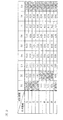
ここで、図3に、ズームレンズ32のレンズ位置(焦点距離)およびフォーカスレンズ33のレンズ位置(撮影距離)と、像面移動係数Kとの関係を示すテーブルを示す。図3に示すテーブルにおいては、ズームレンズ32の駆動領域を、ワイド端からテレ端に向かって順に、「f1」〜「f9」の9つの領域に分けるとともに、フォーカスレンズ33の駆動領域を至近端から無限遠端に向かって順に、「D1」〜「D9」の9つの領域に分けて、各レンズ位置に対応する像面移動係数Kが記憶されている。たとえば、ズームレンズ32のレンズ位置(焦点距離)が「f1」にあり、フォーカスレンズ33のレンズ位置(撮影距離)が「D1」にある場合に、像面移動係数Kは「K11」となる。なお、図3に示すテーブルは、各レンズの駆動領域をそれぞれ9つの領域に分けるような態様を例示したが、その数は特に限定されず、任意に設定することができる。   FIG. 3 shows a table showing the relationship between the lens position (focal length) of the zoom lens 32 and the lens position (shooting distance) of the focus lens 33 and the image plane movement coefficient K. In the table shown in FIG. 3, the drive region of the zoom lens 32 is divided into nine regions “f1” to “f9” in order from the wide end to the tele end, and the drive region of the focus lens 33 is closest. In order from the end toward the end at infinity, the image plane movement coefficient K corresponding to each lens position is stored in nine areas “D1” to “D9”. For example, when the lens position (focal length) of the zoom lens 32 is “f1” and the lens position (shooting distance) of the focus lens 33 is “D1”, the image plane movement coefficient K is “K11”. The table shown in FIG. 3 exemplifies a mode in which the driving area of each lens is divided into nine areas, but the number is not particularly limited and can be arbitrarily set.

次に、図3を用いて、最小像面移動係数Kminおよび最大像面移動係数Kmaxについて説明する。
最小像面移動係数Kminとは、像面移動係数Kの最小値に対応する値である。例えば、図3において、「K11」=「100」、「K12」=「200」、「K13」=「300」、「K14」=「400」、「K15」=「500」、「K16」=「600」、「K17」=「700」、「K18」=「800」、「K19」=「900」であったとき、最小の値である「K11」=「100」が最小像面移動係数Kminであり、最大の値である「K19」=「900」が最大像面移動係数Kmaxである。
最小像面移動係数Kminは、通常、ズームレンズ32の現在のレンズ位置に応じて変化する。また、最小像面移動係数Kminは、ズームレンズ32の現在のレンズ位置が変化しなければ、通常、フォーカスレンズ33の現在のレンズ位置が変化しても一定値(固定値)である。つまり、最小像面移動係数Kminは、通常、ズームレンズ32のレンズ位置(焦点距離)に応じて定まる固定値(一定値)であって、フォーカスレンズ33のレンズ位置(撮影距離)には依存しない値である。
Next, the minimum image plane movement coefficient K min and the maximum image plane movement coefficient K max will be described with reference to FIG.
The minimum image plane movement coefficient K min is a value corresponding to the minimum value of the image plane movement coefficient K. For example, in FIG. 3, “K11” = “100”, “K12” = “200”, “K13” = “300”, “K14” = “400”, “K15” = “500”, “K16” = When “600”, “K17” = “700”, “K18” = “800”, “K19” = “900”, the minimum value “K11” = “100” is the minimum image plane movement coefficient. K min , and the maximum value “K19” = “900” is the maximum image plane movement coefficient K max .
The minimum image plane movement coefficient K min usually changes according to the current lens position of the zoom lens 32. Further, the minimum image plane movement coefficient K min is generally a constant value (fixed value) even if the current lens position of the focus lens 33 changes unless the current lens position of the zoom lens 32 changes. That is, the minimum image plane movement coefficient K min is a fixed value (fixed value) that is normally determined according to the lens position (focal length) of the zoom lens 32 and depends on the lens position (shooting distance) of the focus lens 33. Not a value.

たとえば、図3において、灰色で示した「K11」、「K21」、「K31」、「K41」、「K52」、「K62」、「K72」、「K82」、「K91」は、ズームレンズ32の各レンズ位置(焦点距離)における、像面移動係数Kのうち、最小となる値を示す最小像面移動係数Kminである。すなわち、ズームレンズ32のレンズ位置(焦点距離)が「f1」にある場合には、「D1」〜「D9」のうち、フォーカスレンズ33のレンズ位置(撮影距離)が「D1」にある場合の像面移動係数Kである「K11」が、最小の値を示す最小像面移動係数Kminとなる。したがって、フォーカスレンズ33のレンズ位置(撮影距離)が「D1」にある場合の像面移動係数Kである「K11」は、フォーカスレンズ33のレンズ位置(撮影距離)が「D1」〜「D9」にある場合の像面移動係数Kである「K11」〜「K19」の中で、最も小さな値を示すものとなる。また、同様に、ズームレンズ32のレンズ位置(焦点距離)が「f2」である場合も、フォーカスレンズ33のレンズ位置(撮影距離)が「D1」にある場合の像面移動係数Kである「K21」が、「D1」〜「D9」にある場合の像面移動係数Kである「K21」〜「K29」の中で、最も小さな値を示すものとなる。すなわち、「K21」が最小像面移動係数Kminとなる。以下、同様に、ズームレンズ32の各レンズ位置(焦点距離)が「f3」〜「f9」である場合でも、灰色で示した「K31」、「K41」、「K52」、「K62」、「K72」、「K82」、「K91」が、それぞれ最小像面移動係数Kminとなる。 For example, in FIG. 3, “K11”, “K21”, “K31”, “K41”, “K52”, “K62”, “K72”, “K82”, and “K91” shown in gray are the zoom lens 32. The minimum image plane movement coefficient K min indicating a minimum value among the image plane movement coefficients K at the respective lens positions (focal lengths). That is, when the lens position (focal length) of the zoom lens 32 is “f1”, the lens position (shooting distance) of the focus lens 33 among “D1” to “D9” is “D1”. “K11” which is the image plane movement coefficient K is the minimum image plane movement coefficient K min indicating the minimum value. Accordingly, “K11”, which is the image plane movement coefficient K when the lens position (shooting distance) of the focus lens 33 is “D1”, has a lens position (shooting distance) of the focus lens 33 of “D1” to “D9”. Is the smallest value among the image plane movement coefficients K “K11” to “K19”. Similarly, when the lens position (focal length) of the zoom lens 32 is “f2”, the image plane movement coefficient K is “when the lens position (shooting distance) of the focus lens 33 is“ D1 ”. “K21” indicates the smallest value among “K21” to “K29”, which are image plane movement coefficients K when “K1” is “D1” to “D9”. That is, “K21” is the minimum image plane movement coefficient K min . Similarly, even when each lens position (focal length) of the zoom lens 32 is “f3” to “f9”, “K31”, “K41”, “K52”, “K62”, “K” shown in gray “K72”, “K82”, and “K91” are the minimum image plane movement coefficient K min .

同様に、最大像面移動係数Kmaxとは、像面移動係数Kの最大値に対応する値である。最大像面移動係数Kmaxは、通常、ズームレンズ32の現在のレンズ位置に応じて変化する。また、最大像面移動係数Kmaxは、通常、ズームレンズ32の現在のレンズ位置が変化しなければフォーカスレンズ33の現在のレンズ位置が変化しても一定値(固定値)である。たとえば、図3において、ハッチングを施して示した「K19」、「K29」、「K39」、「K49」、「K59」、「K69」、「K79」、「K89」、「K99」は、ズームレンズ32の各レンズ位置(焦点距離)における、像面移動係数Kのうち、最大となる値を示す最大像面移動係数Kmaxである。 Similarly, the maximum image plane movement coefficient K max is a value corresponding to the maximum value of the image plane movement coefficient K. The maximum image plane movement coefficient K max usually changes according to the current lens position of the zoom lens 32. Further, the maximum image plane movement coefficient K max is generally a constant value (fixed value) even if the current lens position of the focus lens 33 changes unless the current lens position of the zoom lens 32 changes. For example, in FIG. 3, “K19”, “K29”, “K39”, “K49”, “K59”, “K69”, “K79”, “K89”, “K99” shown by hatching are zoomed. This is the maximum image plane movement coefficient K max indicating the maximum value among the image plane movement coefficients K at each lens position (focal length) of the lens 32.

このように、レンズメモリ38は、図3に示すように、ズームレンズ32のレンズ位置(焦点距離)、およびフォーカスレンズ33のレンズ位置(撮影距離)に対応する像面移動係数Kと、ズームレンズ32のレンズ位置(焦点距離)ごとに、像面移動係数Kのうち最小となる値を示す最小像面移動係数Kminと、ズームレンズ32のレンズ位置(焦点距離)ごとに、像面移動係数Kのうち最大となる値を示す最大像面移動係数Kmaxとを記憶している。 Thus, as shown in FIG. 3, the lens memory 38 includes an image plane movement coefficient K corresponding to the lens position (focal length) of the zoom lens 32 and the lens position (shooting distance) of the focus lens 33, and the zoom lens. For each of the 32 lens positions (focal length), the minimum image plane movement coefficient K min indicating the minimum value of the image plane movement coefficient K, and for each lens position (focal length) of the zoom lens 32, the image plane movement coefficient. A maximum image plane movement coefficient K max indicating the maximum value of K is stored.

また、レンズメモリ38は、像面移動係数Kのうち最小となる値を示す最小像面移動係数Kminの代わりに、最小像面移動係数Kminの近傍の値である最小像面移動係数Kmin’をレンズメモリ38に記憶していてもよい。たとえば、最小像面移動係数Kminの値が102.345という桁数の大きい数字であった場合、102.345の近傍の値である100を最小像面移動係数Kmin’として記憶することができる。レンズメモリ38に100(最小像面移動係数Kmin’)を記憶する場合、レンズメモリ38に102.345(最小像面移動係数Kmin)を記憶する場合と比較して、メモリの記憶容量を節約できるとともに、カメラボディ2への送信時に送信データの容量を抑えることができるからである。
また、たとえば、最小像面移動係数Kminの値が100という数字であった場合、後述するガタ詰め制御、静音制御(クリップ動作)、レンズ速度制御等の制御の安定性を考慮して、100の近傍の値である98を最小像面移動係数Kmin’として記憶することができる。たとえば、制御の安定性を考慮する場合には、実際の値(最小像面移動係数Kmin)の80%〜120%の範囲で最小像面移動係数Kmin’を設定することが好ましい。
The lens memory 38 is smallest in place of the minimum image plane shift factor K min indicating the value, the minimum image plane shift factor K is a value in the vicinity of the minimum image plane shift factor K min of the image plane shift factor K min ′ may be stored in the lens memory 38. For example, when the value of the minimum image plane movement coefficient K min is a large number of digits of 102.345, 100, which is a value in the vicinity of 102.345, may be stored as the minimum image plane movement coefficient K min ′. it can. When 100 (minimum image plane movement coefficient K min ′) is stored in the lens memory 38, the memory capacity of the memory is larger than when 102.345 (minimum image plane movement coefficient K min ) is stored in the lens memory 38. This is because saving can be achieved and the capacity of transmission data can be suppressed during transmission to the camera body 2.
Further, for example, when the value of the minimum image plane movement coefficient K min is 100, 100 is considered in consideration of the stability of control such as backlash control, silent control (clip operation), lens speed control and the like which will be described later. 98, which is a value in the vicinity of, can be stored as the minimum image plane movement coefficient K min ′. For example, when considering the control stability, it is preferable to set the minimum image plane movement coefficient K min ′ within the range of 80% to 120% of the actual value (minimum image plane movement coefficient K min ).

加えて、本実施形態においては、レンズメモリ38には、上述した最小像面移動係数Kminおよび最大像面移動係数Kmaxに加えて、これらの係数を補正することで得られた補正最小像面移動係数Kmin_xおよび補正最大像面移動係数Kmax_xを記憶している。図4に、ズームレンズ32のレンズ位置(焦点距離)と、最小像面移動係数Kminおよび最大像面移動係数Kmax、ならびに補正最小像面移動係数Kmin_xおよび補正最大像面移動係数Kmax_xとの関係を示すテーブルを示す。 In addition, in the present embodiment, in addition to the above-mentioned minimum image plane movement coefficient K min and maximum image plane movement coefficient K max , the lens memory 38 includes a corrected minimum image obtained by correcting these coefficients. The plane movement coefficient K min — x and the corrected maximum image plane movement coefficient K max — x are stored. 4, the lens position of the zoom lens 32 (focal length) and the minimum image plane shift factor K min and maximum image plane shift factor K max, and correcting the minimum image plane shift factor K min_x and correcting the maximum image plane shift factor K max_x The table which shows the relationship with is shown.

すなわち、図4に示すように、ズームレンズ32のレンズ位置(焦点距離)が「f1」にある場合を例示して説明すると、レンズメモリ38には、最小像面移動係数Kminとしての「K11」に加えて、補正最小像面移動係数Kmin_xとしての「K11’」が記憶されており、同様に、最大像面移動係数Kmaxとしての「K91」に加えて、補正最大像面移動係数Kmax_xとしての「K91’」が記憶されている。同様に、ズームレンズ32の各レンズ位置(焦点距離)が「f2」〜「f9」である場合に対しても、図4に示すように、補正最小像面移動係数Kmin_xとして、「K21’」、「K31’」、「K41’」、「K52’」、「K62’」、「K72’」、「K82’」、「K91’」が記憶されており、補正最大像面移動係数Kmax_xとして、「K29’」、「K39’」、「K49’」、「K59’」、「K69’」、「K79’」、「K89’」、「K99’」が記憶されている。 That is, as illustrated in FIG. 4, the case where the lens position (focal length) of the zoom lens 32 is “f1” will be described as an example. The lens memory 38 stores “K11 as a minimum image plane movement coefficient K min. in addition to ", and" K11 '' as the correction minimum image plane shift factor K min_x are stored, as well, in addition to "K91" in the maximum image plane shift factor K max, the correction maximum image plane shift factor “K91 ′” as K max — x is stored. Similarly, even when the lens positions (focal lengths) of the zoom lens 32 are “f2” to “f9”, as shown in FIG. 4, the corrected minimum image plane movement coefficient K min — x is “K21 ′”. ”,“ K31 ′ ”,“ K41 ′ ”,“ K52 ′ ”,“ K62 ′ ”,“ K72 ′ ”,“ K82 ′ ”,“ K91 ′ ”are stored, and the corrected maximum image plane movement coefficient K max — x “K29 ′”, “K39 ′”, “K49 ′”, “K59 ′”, “K69 ′”, “K79 ′”, “K89 ′”, “K99 ′” are stored.

なお、補正最小像面移動係数Kmin_xとしては、最小像面移動係数Kminを補正することにより得られる係数であればよく、特に限定されず、最小像面移動係数Kminよりも大きな値を有するもの、あるいは、最小像面移動係数Kminよりも小さな値を有するものいずれであってもよく、その目的等に応じて適宜設定すればよい。たとえば、本実施形態においては、後述するように、最小像面移動係数Kminはフォーカスレンズ33のスキャン動作を行う際におけるスキャン駆動速度Vを決定するために用いることができる。しかしその一方で、最小像面移動係数Kminを用いた場合には、ブレ補正レンズ34の位置や、カメラ1の姿勢によっては、これらの影響により、必ずしも適切なスキャン駆動速度Vを算出できない場合がある。そのため、本実施形態においては、補正最小像面移動係数Kmin_xとしては、ブレ補正レンズ34の位置や、カメラ1の姿勢の影響を考慮したものを採用することが望ましい。ただし、このような態様に特に限定されるものではない。また、上述した例においては、補正最小像面移動係数Kmin_xを一つのみ有する構成を例示したが、補正最小像面移動係数Kmin_xを複数有するような構成としてもよい。 As the correction minimum image plane shift factor K min_x, it may be a coefficient obtained by correcting the minimum image plane shift factor K min, not particularly limited, a value larger than the minimum image plane shift factor K min Or having a value smaller than the minimum image plane movement coefficient K min , and may be set appropriately according to the purpose and the like. For example, in the present embodiment, as will be described later, the minimum image plane movement coefficient K min can be used to determine the scan drive speed V when performing the scan operation of the focus lens 33. However, on the other hand, when the minimum image plane movement coefficient K min is used, an appropriate scan drive speed V cannot always be calculated due to the influence of the position of the blur correction lens 34 and the posture of the camera 1. There is. Therefore, in the present embodiment, it is desirable to adopt a correction minimum image plane movement coefficient K min — x that takes into account the influence of the position of the shake correction lens 34 and the posture of the camera 1. However, it is not particularly limited to such an embodiment. In the above-described example, the configuration having only one corrected minimum image plane movement coefficient K min — x is illustrated, but a configuration having a plurality of corrected minimum image plane movement coefficients K min — x may be used.

さらに、補正最大像面移動係数Kmax_xとしては最大像面移動係数Kmaxを補正することにより得られる係数であればよく、特に限定されず、最大像面移動係数Kmaxよりも大きな値を有するもの、あるいは、最大像面移動係数Kmaxよりも小さな値を有するものいずれであってもよく、その目的等に応じて適宜設定すればよい。また、上述した例においては、補正最大像面移動係数Kmax_xを一つのみ有する構成を例示したが、補正最大像面移動係数Kmax_xを複数有するような構成としてもよい。 Further, the corrected maximum image plane movement coefficient K max — x may be any coefficient obtained by correcting the maximum image plane movement coefficient K max, and is not particularly limited and has a value larger than the maximum image plane movement coefficient K max. Any one having a value smaller than the maximum image plane movement coefficient K max may be used, and may be set as appropriate according to the purpose. In the above-described example, the configuration having only one corrected maximum image plane movement coefficient K max — x is illustrated, but a configuration having a plurality of corrected maximum image plane movement coefficients K max — x may be used.

次いで、カメラ本体2とレンズ鏡筒3との間のデータの通信方法について説明する。   Next, a data communication method between the camera body 2 and the lens barrel 3 will be described.

カメラ本体2には、レンズ鏡筒3が着脱可能に取り付けられるボディ側マウント部201が設けられている。また、図1に示すように、ボディ側マウント部201の近傍(ボディ側マウント部201の内面側)の位置には、ボディ側マウント部201の内面側に突出する接続部202が設けられている。この接続部202には複数の電気接点が設けられている。   The camera body 2 is provided with a body side mount portion 201 to which the lens barrel 3 is detachably attached. Further, as shown in FIG. 1, a connection portion 202 that protrudes to the inner surface side of the body side mount portion 201 is provided in the vicinity of the body side mount portion 201 (inner surface side of the body side mount portion 201). . The connection portion 202 is provided with a plurality of electrical contacts.

一方、レンズ鏡筒3は、カメラ本体2に着脱可能な交換レンズであり、レンズ鏡筒3には、カメラ本体2に着脱可能に取り付けられるレンズ側マウント部301が設けられている。また、図1に示すように、レンズ側マウント部301の近傍(レンズ側マウント部301の内面側)の位置には、レンズ側マウント部301の内面側に突出する接続部302が設けられている。この接続部302には複数の電気接点が設けられている。   On the other hand, the lens barrel 3 is an interchangeable lens that can be attached to and detached from the camera body 2, and the lens barrel 3 is provided with a lens side mount portion 301 that is detachably attached to the camera body 2. Further, as shown in FIG. 1, a connection portion 302 that protrudes to the inner surface side of the lens side mount portion 301 is provided in the vicinity of the lens side mount portion 301 (inner surface side of the lens side mount portion 301). . The connecting portion 302 is provided with a plurality of electrical contacts.

そして、カメラ本体2にレンズ鏡筒3が装着されると、ボディ側マウント部201に設けられた接続部202の電気接点と、レンズ側マウント部301に設けられた接続部302の電気接点とが、電気的かつ物理的に接続される。これにより、接続部202,302を介して、カメラ本体2からレンズ鏡筒3への電力供給や、カメラ本体2とレンズ鏡筒3とのデータ通信が可能となる。   When the lens barrel 3 is attached to the camera body 2, an electrical contact of the connection portion 202 provided on the body side mount portion 201 and an electrical contact of the connection portion 302 provided on the lens side mount portion 301 are obtained. Electrically and physically connected. Thereby, power supply from the camera body 2 to the lens barrel 3 and data communication between the camera body 2 and the lens barrel 3 can be performed via the connection units 202 and 302.

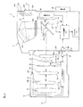
図5は接続部202,302の詳細を示す模式図である。なお、図5において接続部202がボディ側マウント部201の右側に配置されているのは、実際のマウント構造に倣ったものである。すなわち、本実施形態の接続部202は、ボディ側マウント部201のマウント面よりも奥まった場所(図5においてボディ側マウント部201よりも右側の場所)に配置されている。同様に、接続部302がレンズ側マウント部301の右側に配置されているのは、本実施形態の接続部302がレンズ側マウント部301のマウント面よりも突出した場所に配置されていることを表している。接続部202と接続部302とがこのように配置されることで、ボディ側マウント部201のマウント面とレンズ側マウント部301のマウント面とを接触させて、カメラ本体2とレンズ鏡筒3とをマウント結合させた場合に、接続部202と接続部302とが接続され、これにより、両方の接続部202,302に設けられている電気接点同士が接続する。   FIG. 5 is a schematic diagram showing details of the connecting sections 202 and 302. In FIG. 5, the connection portion 202 is arranged on the right side of the body-side mount portion 201 in accordance with the actual mount structure. In other words, the connection portion 202 of this embodiment is disposed at a location deeper than the mount surface of the body side mount portion 201 (a location on the right side of the body side mount portion 201 in FIG. 5). Similarly, the connection portion 302 is disposed on the right side of the lens side mount portion 301 because the connection portion 302 of the present embodiment is disposed at a position protruding from the mount surface of the lens side mount portion 301. Represents. By arranging the connection portion 202 and the connection portion 302 in this way, the mount surface of the body-side mount portion 201 and the mount surface of the lens-side mount portion 301 are brought into contact with each other, so that the camera body 2 and the lens barrel 3 Are connected to each other, the connecting portion 202 and the connecting portion 302 are connected to each other, and the electrical contacts provided in both the connecting portions 202 and 302 are connected to each other.

図5に示すように、接続部202にはBP1〜BP12の12個の電気接点が存在する。またレンズ3側の接続部302には、カメラ本体2側の12個の電気接点にそれぞれ対応するLP1〜LP12の12個の電気接点が存在する。   As shown in FIG. 5, twelve electrical contacts BP <b> 1 to BP <b> 12 exist in the connection unit 202. Further, twelve electrical contacts LP1 to LP12 corresponding to the twelve electrical contacts on the camera body 2 side exist in the connection portion 302 on the lens 3 side.

電気接点BP1および電気接点BP2は、カメラ本体2内の第1電源回路230に接続されている。第1電源回路230は、電気接点BP1および電気接点LP1を介して、レンズ鏡筒3内の各部(ただし、レンズ駆動モータ321,331などの消費電力が比較的大きい回路を除く)に動作電圧を供給する。電気接点BP1および電気接点LP1を介して、第1電源回路230により供給される電圧値は、特に限定されず、たとえば3〜4Vの電圧値(標準的には、この電圧幅の中間にある3.5V近傍の電圧値)とすることができる。この場合、カメラ本体側2からレンズ鏡筒側3に供給される電流値は、電源オン状態において、約数10mA〜数100mAの範囲内の電流値となる。また、電気接点BP2および電気接点LP2は、電気接点BP1および電気接点LP1を介して供給される上記動作電圧に対応する接地端子である。   The electrical contacts BP1 and BP2 are connected to the first power supply circuit 230 in the camera body 2. The first power supply circuit 230 supplies an operating voltage to each part in the lens barrel 3 (except for circuits with relatively large power consumption such as the lens drive motors 321 and 331) via the electrical contact BP1 and the electrical contact LP1. Supply. The voltage value supplied by the first power supply circuit 230 via the electrical contact BP1 and the electrical contact LP1 is not particularly limited, and is, for example, a voltage value of 3 to 4 V (typically 3 in the middle of this voltage width). Voltage value in the vicinity of 0.5 V). In this case, the current value supplied from the camera body side 2 to the lens barrel side 3 is a current value within a range of about several tens mA to several hundred mA in the power-on state. Further, the electrical contact BP2 and the electrical contact LP2 are ground terminals corresponding to the operation voltage supplied via the electrical contact BP1 and the electrical contact LP1.

電気接点BP3〜BP6は、カメラ側第1通信部291に接続されており、これら電気接点BP3〜BP6に対応して、電気接点LP3〜LP6が、レンズ側第1通信部381に接続されている。そして、カメラ側第1通信部291とレンズ側第1通信部381とは、これらの電気接点を用いて互いに信号の送受信を行う。なお、カメラ側第1通信部291とレンズ側第1通信部381とが行う通信の内容については、後に詳述する。   The electrical contacts BP3 to BP6 are connected to the camera side first communication unit 291. Corresponding to these electrical contacts BP3 to BP6, the electrical contacts LP3 to LP6 are connected to the lens side first communication unit 381. . The camera-side first communication unit 291 and the lens-side first communication unit 381 transmit and receive signals to and from each other using these electrical contacts. The contents of communication performed by the camera-side first communication unit 291 and the lens-side first communication unit 381 will be described in detail later.

電気接点BP7〜BP10は、カメラ側第2通信部292に接続されており、これら電気接点BP7〜BP10に対応して、電気接点LP7〜LP10が、レンズ側第2通信部382に接続されている。そして、カメラ側第2通信部292とレンズ側第2通信部382とは、これらの電気接点を用いて互いに信号の送受信を行う。なお、カメラ側第2通信部292とレンズ側第2通信部382とが行う通信の内容については、後に詳述する。   The electrical contacts BP7 to BP10 are connected to the camera-side second communication unit 292, and the electrical contacts LP7 to LP10 are connected to the lens-side second communication unit 382 corresponding to the electrical contacts BP7 to BP10. . And the camera side 2nd communication part 292 and the lens side 2nd communication part 382 mutually transmit / receive a signal using these electrical contacts. The contents of communication performed by the camera side second communication unit 292 and the lens side second communication unit 382 will be described in detail later.

電気接点BP11および電気接点BP12は、カメラ本体2内の第2電源回路240に接続されている。第2電源回路240は、電気接点BP11および電気接点LP11を介して、レンズ駆動モータ321,331などの消費電力が比較的大きい回路に動作電圧を供給する。第2電源回路230により供給される電圧値は、特に限定されないが、第2電源回路240により供給される電圧値の最大値は、第1電源回路230により供給される電圧値の最大値の数倍程度とすることができる。また、この場合、第2電源回路240からレンズ鏡筒3側に供給される電流値は、電源オン状態において、約数10mA〜数Aの範囲内の電流値となる。また、電気接点BP12および電気接点LP12は、電気接点BP11および電気接点LP11を介して供給される上記動作電圧に対応する接地端子である。   The electrical contacts BP11 and BP12 are connected to a second power supply circuit 240 in the camera body 2. The second power supply circuit 240 supplies an operating voltage to circuits with relatively large power consumption, such as the lens drive motors 321 and 331, via the electrical contact BP11 and the electrical contact LP11. The voltage value supplied by the second power supply circuit 230 is not particularly limited, but the maximum voltage value supplied by the second power supply circuit 240 is the number of maximum voltage values supplied by the first power supply circuit 230. It can be about double. In this case, the current value supplied from the second power supply circuit 240 to the lens barrel 3 side is a current value within a range of about several tens of mA to several A in the power-on state. The electrical contact BP12 and the electrical contact LP12 are ground terminals corresponding to the operating voltage supplied through the electrical contact BP11 and the electrical contact LP11.

なお、図5に示すカメラ本体2側の第1通信部291および第2通信部292は、図1に示すカメラ送受信部29を構成し、図5に示すレンズ鏡筒3側の第1通信部381および第2通信部382は、図1に示すレンズ送受信部38を構成する。   The first communication unit 291 and the second communication unit 292 on the camera body 2 side shown in FIG. 5 constitute the camera transmission / reception unit 29 shown in FIG. 1, and the first communication unit on the lens barrel 3 side shown in FIG. 381 and the second communication unit 382 constitute the lens transmission / reception unit 38 shown in FIG.

次に、カメラ側第1通信部291とレンズ側第1通信部381との通信(以下、コマンドデータ通信という)について説明する。レンズ制御部37は、電気接点BP3およびLP3から構成される信号線CLKと、電気接点BP4およびLP4から構成される信号線BDATと、電気接点BP5およびLP5から構成される信号線LDATと、電気接点BP6およびLP6から構成される信号線RDYとを介して、カメラ側第1通信部291からレンズ側第1通信部381への制御データの送信と、レンズ側第1通信部381からカメラ側第1通信部291への応答データの送信とを、並行して、所定の周期(たとえば、16ミリ秒間隔)で行う、コマンドデータ通信を行う。   Next, communication between the camera-side first communication unit 291 and the lens-side first communication unit 381 (hereinafter referred to as command data communication) will be described. The lens control unit 37 includes a signal line CLK composed of electrical contacts BP3 and LP3, a signal line BDAT composed of electrical contacts BP4 and LP4, a signal line LDAT composed of electrical contacts BP5 and LP5, and electrical contacts Transmission of control data from the camera-side first communication unit 291 to the lens-side first communication unit 381 via the signal line RDY composed of BP6 and LP6, and the lens-side first communication unit 381 to the camera-side first Command data communication is performed in parallel with transmission of response data to the communication unit 291 at a predetermined cycle (for example, at intervals of 16 milliseconds).

図6は、コマンドデータ通信の一例を示すタイミングチャートである。カメラ制御部21およびカメラ側第1通信部291は、コマンドデータ通信の開始時(T1)に、まず、信号線RDYの信号レベルを確認する。ここで、信号線RDYの信号レベルはレンズ側第1通信部381の通信可否を表しており、通信不可の場合には、レンズ制御部37およびレンズ側第1通信部381により、H(High)レベルの信号が出力される。カメラ側第1通信部291は、信号線RDYがHレベルである場合には、レンズ鏡筒3との通信を行わず、または、通信中である場合にも、次の処理を実行しない。   FIG. 6 is a timing chart showing an example of command data communication. The camera control unit 21 and the first camera-side communication unit 291 first confirm the signal level of the signal line RDY at the start of command data communication (T1). Here, the signal level of the signal line RDY indicates whether the lens-side first communication unit 381 is communicable. If communication is not possible, the lens control unit 37 and the lens-side first communication unit 381 perform H (High). A level signal is output. The first camera-side communication unit 291 does not perform communication with the lens barrel 3 when the signal line RDY is at the H level, or does not execute the next process even during communication.

一方、信号線RDYがL(LOW)レベルである場合、カメラ制御部21およびカメラ側第1通信部291は、信号線CLKを用いて、クロック信号401をレンズ側第1通信部291に送信する。また、カメラ制御部21およびカメラ側第1通信部291は、このクロック信号401に同期して、信号線BDATを用いて、制御データであるカメラ側コマンドパケット信号402をレンズ側第1通信部291に送信する。また、クロック信号401が出力されると、レンズ制御部37およびレンズ側第1通信部381は、このクロック信号401に同期して、信号線LDATを用いて、応答データであるレンズ側コマンドパケット信号403を送信する。   On the other hand, when the signal line RDY is at the L (LOW) level, the camera control unit 21 and the camera-side first communication unit 291 transmit the clock signal 401 to the lens-side first communication unit 291 using the signal line CLK. . Further, the camera control unit 21 and the camera side first communication unit 291 use the signal line BDAT in synchronization with the clock signal 401 to transmit the camera side command packet signal 402 as control data to the lens side first communication unit 291. Send to. When the clock signal 401 is output, the lens control unit 37 and the first lens-side communication unit 381 synchronize with the clock signal 401 and use the signal line LDAT to send a lens-side command packet signal that is response data. 403 is transmitted.

レンズ制御部37およびレンズ側第1通信部291は、レンズ側コマンドパケット信号403の送信完了に応じて、信号線RDYの信号レベルをLレベルからHレベルに変更する(T2)。そして、レンズ制御部37は、時刻T2までに受信したボディ側コマンドパケット信号402の内容に応じて、第1制御処理404を開始する。   The lens control unit 37 and the first lens-side communication unit 291 change the signal level of the signal line RDY from the L level to the H level in response to the completion of transmission of the lens-side command packet signal 403 (T2). Then, the lens control unit 37 starts the first control process 404 according to the content of the body side command packet signal 402 received up to time T2.

たとえば、受信したボディ側コマンドパケット信号402が、レンズ鏡筒3側の特定のデータを要求する内容であった場合、レンズ制御部37は、第1制御処理404として、コマンドパケット信号402の内容を解析するとともに、要求された特定データを生成する処理を実行する。さらに、レンズ制御部37は、第1制御処理404として、コマンドパケット信号402に含まれているチェックサムデータを用いて、コマンドパケット信号402の通信にエラーがないか否かをデータバイト数から簡易的にチェックする通信エラーチェック処理をも実行する。この第1制御処理404で生成された特定データの信号は、レンズ側データパケット信号407としてカメラ本体2側に出力される(T3)。なお、この場合においてコマンドパケット信号402の後でカメラ本体2側から出力されるカメラ側データパケット信号406は、レンズ側にとっては特に意味をなさないダミーデータ (チェックサムデータは含む)となっている。この場合には、レンズ制御部37は、第2制御処理408として、カメラ側データパケット信号406に含まれるチェックサムデータを用いた、上述の如き通信エラーチェック処理を実行する(T4)。   For example, when the received body-side command packet signal 402 is content requesting specific data on the lens barrel 3 side, the lens control unit 37 uses the content of the command packet signal 402 as the first control processing 404. Along with the analysis, a process for generating the requested specific data is executed. Further, as the first control process 404, the lens control unit 37 uses the checksum data included in the command packet signal 402 to simplify whether there is no error in the communication of the command packet signal 402 from the number of data bytes. A communication error check process is also executed. The specific data signal generated in the first control process 404 is output to the camera body 2 side as a lens-side data packet signal 407 (T3). In this case, the camera-side data packet signal 406 output from the camera body 2 side after the command packet signal 402 is dummy data (including checksum data) that has no particular meaning for the lens side. . In this case, the lens control unit 37 executes the communication error check process as described above using the checksum data included in the camera-side data packet signal 406 as the second control process 408 (T4).

また、たとえば、カメラ側コマンドパケット信号402が、フォーカスレンズ33の駆動指示であり、カメラ側データパケット信号406がフォーカスレンズ33の駆動速度および駆動量であった場合、レンズ制御部37は、第1制御処理404として、コマンドパケット信号402の内容を解析するとともに、その内容を理解したことを表す確認信号を生成する(T2)。この第1制御処理404で生成された確認信号は、レンズ側データパケット信号407としてカメラ本体2に出力される(T3)。またレンズ制御部37は、第2制御処理408として、カメラ側データパケット信号406の内容の解析を実行するとともに、カメラ側データパケット信号406に含まれるチェックサムデータを用いて通信エラーチェック処理を実行する(T4)。そして、第2制御処理408の完了後、レンズ制御部37は、受信したカメラ側コマンドパケット信号406、すなわち、フォーカスレンズ33の駆動速度および駆動量に基づいて、フォーカスレンズ駆動モータ331を駆動させることで、フォーカスレンズ33を、受信した駆動速度で、受信した駆動量だけ駆動させる(T5)。   For example, when the camera-side command packet signal 402 is an instruction to drive the focus lens 33 and the camera-side data packet signal 406 is the drive speed and drive amount of the focus lens 33, the lens control unit 37 As the control process 404, the contents of the command packet signal 402 are analyzed, and a confirmation signal indicating that the contents have been understood is generated (T2). The confirmation signal generated in the first control process 404 is output to the camera body 2 as a lens-side data packet signal 407 (T3). In addition, as the second control process 408, the lens control unit 37 analyzes the contents of the camera-side data packet signal 406 and executes a communication error check process using the checksum data included in the camera-side data packet signal 406. (T4). After the completion of the second control processing 408, the lens control unit 37 drives the focus lens drive motor 331 based on the received camera side command packet signal 406, that is, the drive speed and drive amount of the focus lens 33. Thus, the focus lens 33 is driven at the received drive speed by the received drive amount (T5).

また、レンズ制御部37は、第2制御処理408が完了すると、レンズ側第1通信部291に第2制御処理408の完了を通知する。これにより、レンズ制御部37は、信号線RDYにLレベルの信号を出力する(T5)。   In addition, when the second control process 408 is completed, the lens control unit 37 notifies the lens-side first communication unit 291 that the second control process 408 is completed. Thereby, the lens control unit 37 outputs an L level signal to the signal line RDY (T5).

上述した時刻T1〜T5の間に行われた通信が、 1回のコマンドデータ通信である。上述のように、1回のコマンドデータ通信では、カメラ制御部21およびカメラ側第1通信部291により、カメラ側コマンドパケット信号402およびカメラ側テータパケット信号406がそれぞれ1つずつ送信される。このように、本実施形態では、カメラ本体2からレンズ鏡筒3に送信される制御データは、処理の都合上2つに分割されて送信されているが、カメラ側コマンドパケット信号402およびカメラ側データパケット信号406は2つ合わせて1つの制御データを構成するものである。   The communication performed between the times T1 to T5 described above is one command data communication. As described above, in one command data communication, the camera-side command packet signal 402 and the camera-side data packet signal 406 are transmitted one by one by the camera control unit 21 and the camera-side first communication unit 291, respectively. As described above, in the present embodiment, the control data transmitted from the camera body 2 to the lens barrel 3 is divided into two for convenience of processing, but the camera side command packet signal 402 and the camera side are transmitted. Two data packet signals 406 constitute one control data.

同様に、1回のコマンドデータ通信では、レンズ制御部37およびレンズ側第1通信部381によりレンズ側コマンドパケット信号403およびレンズ側データパケット信号407がそれぞれ1つずつ送信される。このように、レンズ鏡筒3からカメラ本体2に送信される応答データも2つに分割されているが、レンズ側コマンドパケット信号403とレンズ側データパケット信号407とも2つ合わせて1つの応答データを構成する。   Similarly, in one command data communication, the lens control unit 37 and the lens side first communication unit 381 transmit the lens side command packet signal 403 and the lens side data packet signal 407 one by one. As described above, the response data transmitted from the lens barrel 3 to the camera body 2 is also divided into two, but one response data includes both the lens side command packet signal 403 and the lens side data packet signal 407. Configure.

次に、カメラ側第2通信部292とレンズ側第2通信部382との通信(以下、ホットライン通信という)について説明する。図5に戻り、レンズ制御部37は、電気接点BP7およびLP7から構成される信号線HREQ、電気接点BP8およびLP8から構成される信号線HANS、電気接点BP9およびLP9から構成される信号線HCLK、電気接点BP10およびLP10から構成される信号線HDATを介して、コマンドデータ通信よりも短い周期(たとえば1ミリ秒間隔)で通信を行うホットライン通信を行う。   Next, communication between the camera-side second communication unit 292 and the lens-side second communication unit 382 (hereinafter referred to as hotline communication) will be described. Returning to FIG. 5, the lens control unit 37 includes a signal line HREQ including the electrical contacts BP7 and LP7, a signal line HANS including the electrical contacts BP8 and LP8, and a signal line HCLK including the electrical contacts BP9 and LP9. Hot line communication is performed through the signal line HDAT formed of the electrical contacts BP10 and LP10, in which communication is performed at a cycle shorter than the command data communication (for example, at intervals of 1 millisecond).

たとえば、本実施形態では、ホットライン通信により、レンズ鏡筒3のレンズ情報が、レンズ鏡筒3からカメラ本体2に送信される。なお、ホットライン通信により送信されるレンズ情報には、フォーカスレンズ33のレンズ位置、ズームレンズ32のレンズ位置、現在位置像面移動係数Kcur、最小像面移動係数Kmin、および最大像面移動係数Kmaxが含まれる。ここで、現在位置像面移動係数Kcurとは、現在のズームレンズ32のレンズ位置(焦点距離)および現在のフォーカスレンズ33のレンズ位置(撮影距離)に対応した像面移動係数Kである。本実施形態において、レンズ制御部37は、レンズメモリ38に記憶された、レンズ位置(ズームレンズ位置およびフォーカスレンズ位置)と像面移動係数Kとの関係を示すテーブルを参照することで、ズームレンズ32の現在のレンズ位置およびフォーカスレンズ33の現在のレンズ位置に対応する現在位置像面移動係数Kcurを求めることができる。たとえば、図3に示す例において、ズームレンズ32のレンズ位置(焦点距離)が「f1」にあり、フォーカスレンズ33のレンズ位置(撮影距離)が「D4」にある場合、レンズ制御部37は、ホットライン通信により、現在位置像面移動係数Kcurとして「K14」を、最小像面移動係数Kminとして「K11」を、最大像面移動係数Kmaxとして「K19」をカメラ制御部21に送信する。また、本実施形態においては、後述するように、レンズ情報としての最小像面移動係数Kmin、および最大像面移動係数Kmaxに代えて、上述した補正最小像面移動係数Kmin_x、および補正最大像面移動係数Kmax_xが含まれていてもよい。 For example, in the present embodiment, lens information of the lens barrel 3 is transmitted from the lens barrel 3 to the camera body 2 by hotline communication. The lens information transmitted by hotline communication includes the lens position of the focus lens 33, the lens position of the zoom lens 32, the current position image plane movement coefficient K cur , the minimum image plane movement coefficient K min , and the maximum image plane movement. A coefficient K max is included. Here, the current position image plane movement coefficient K cur is an image plane movement coefficient K corresponding to the current lens position (focal length) of the zoom lens 32 and the current lens position (shooting distance) of the focus lens 33. In the present embodiment, the lens control unit 37 refers to a table stored in the lens memory 38 and indicating the relationship between the lens position (zoom lens position and focus lens position) and the image plane movement coefficient K, so that the zoom lens The current position image plane movement coefficient K cur corresponding to the current lens position of 32 and the current lens position of the focus lens 33 can be obtained. For example, in the example shown in FIG. 3, when the lens position (focal distance) of the zoom lens 32 is “f1” and the lens position (shooting distance) of the focus lens 33 is “D4”, the lens control unit 37 By hot line communication, “K14” is transmitted to the camera control unit 21 as “K14” as the current position image plane movement coefficient K cur , “K11” as the minimum image plane movement coefficient K min , and “K19” as the maximum image plane movement coefficient K max. To do. In the present embodiment, as described later, instead of the minimum image plane movement coefficient K min and the maximum image plane movement coefficient K max as lens information, the above-described corrected minimum image plane movement coefficient K min — x and correction are performed. A maximum image plane movement coefficient K max — x may be included.

ここで、図7は、ホットライン通信の一例を示すタイミングチャートである。図7(a)は、ホットライン通信が所定周期Tn毎に繰り返し実行されている様子を示す図である。また、繰り返し実行されるホットライン通信のうち、ある1回の通信の期間Txを拡大した様子を図7(b)に示す。以下、図7(b)のタイミングチャートに基づいて、フォーカスレンズ33のレンズ位置をホットライン通信で通信する場面を説明する。   Here, FIG. 7 is a timing chart showing an example of hotline communication. FIG. 7A is a diagram illustrating a state in which hotline communication is repeatedly performed at predetermined intervals Tn. Further, FIG. 7B shows a state in which a certain communication period Tx is expanded in hot line communication repeatedly executed. Hereinafter, a scene in which the lens position of the focus lens 33 is communicated by hot line communication will be described based on the timing chart of FIG.

カメラ制御部21およびカメラ側第2通信部292は、まず、ホットライン通信による通信を開始するために、信号線HREQにLレベルの信号を出力する(T6)。そして、レンズ側第2通信部382は、この信号が電気接点LP7に入力されたことを、レンズ制御部37に通知する。レンズ制御部37は、この通知に応じて、レンズ位置データを生成する生成処理501の実行を開始する。生成処理501とは、レンズ制御部37がフォーカスレンズ用エンコーダ332にフォーカスレンズ33の位置を検出させ、検出結果を表すレンズ位置データを生成する処理である。   The camera control unit 21 and the camera-side second communication unit 292 first output an L level signal to the signal line HREQ in order to start communication by hot line communication (T6). Then, the second lens side communication unit 382 notifies the lens control unit 37 that this signal has been input to the electrical contact LP7. In response to this notification, the lens control unit 37 starts executing a generation process 501 that generates lens position data. The generation process 501 is a process in which the lens control unit 37 causes the focus lens encoder 332 to detect the position of the focus lens 33 and generates lens position data representing the detection result.

レンズ制御部37が生成処理501を実行完了すると、レンズ制御部37およびレンズ側第2通信部382は信号線HANSにLレベルの信号を出力する(T7)。そして、カメラ制御部21およびカメラ側第2通信部292は、この信号が電気接点BP8に入力されると、電気接点BP9から信号線HCLKに、クロック信号502を出力する。   When the lens control unit 37 completes the execution of the generation process 501, the lens control unit 37 and the second lens side communication unit 382 output an L level signal to the signal line HANS (T7). When this signal is input to the electrical contact BP8, the camera control unit 21 and the camera-side second communication unit 292 output the clock signal 502 from the electrical contact BP9 to the signal line HCLK.

レンズ制御部37およびレンズ側第2通信部382は、このクロック信号502に同期して、電気接点LP10から信号線HDATに、レンズ位置データを表すレンズ位置データ信号503を出力する。そして、レンズ位置データ信号503の送信が完了すると、レンズ制御部37およびレンズ側第2通信部382は電気接点LP8から信号線HANSにHレベルの信号を出力する(T8)。そして、カメラ側第2通信部292は、この信号が電気接点BP8に入力されると、電気接点LP7から信号線HREQに、Hレベルの信号を出力する(T9)。   The lens control unit 37 and the second lens side communication unit 382 output a lens position data signal 503 representing lens position data from the electrical contact LP10 to the signal line HDAT in synchronization with the clock signal 502. When the transmission of the lens position data signal 503 is completed, the lens control unit 37 and the lens side second communication unit 382 output an H level signal from the electrical contact LP8 to the signal line HANS (T8). Then, when this signal is input to the electrical contact BP8, the second camera-side communication unit 292 outputs an H level signal from the electrical contact LP7 to the signal line HREQ (T9).

なお、コマンドデータ通信とホットライン通信は、同時に、あるいは、並行して実行することが可能である。   Note that command data communication and hotline communication can be executed simultaneously or in parallel.

次いで、図8を参照して、本実施形態に係るカメラ1の動作例を説明する。図8は、本実施形態に係るカメラ1の動作を示すフローチャートである。なお、以下の動作は、カメラ1の電源がオンされることにより開始される。   Next, an operation example of the camera 1 according to the present embodiment will be described with reference to FIG. FIG. 8 is a flowchart showing the operation of the camera 1 according to this embodiment. The following operation is started when the camera 1 is turned on.

まず、ステップS101においては、カメラボディ2がレンズ鏡筒3を識別するための通信を行う。レンズ鏡筒の種類に応じて通信可能な通信形式が異なるからである。そして、ステップS102に進み、ステップS102では、カメラ制御部21は、レンズ鏡筒3が所定の第1種別の通信形式に対応したレンズであるか否かの判断を行う。その結果、第1種別の通信形式に対応したレンズであると判断した場合に、ステップS103に進む。一方、カメラ制御部21は、レンズ鏡筒3が、所定の第1種別の通信形式に対応していないレンズであると判断した場合には、ステップS112に進む。また、カメラ制御部21は、レンズ鏡筒3が、第1種別の通信形式とは異なる第2種別の通信形式に対応しているレンズであると判断した場合、ステップS112に進むようにしてもよい。さらに、カメラ制御部21は、レンズ鏡筒3が第1種別および第2種別の通信形式に対応しているレンズであると判断した場合、ステップS103に進むようにしてもよい。   First, in step S101, the camera body 2 performs communication for identifying the lens barrel 3. This is because communicable communication formats differ depending on the type of lens barrel. In step S102, the camera control unit 21 determines whether the lens barrel 3 is a lens corresponding to a predetermined first type communication format. As a result, when it is determined that the lens is compatible with the first type of communication format, the process proceeds to step S103. On the other hand, if the camera control unit 21 determines that the lens barrel 3 is a lens that does not support the predetermined first type communication format, the process proceeds to step S112. If the camera control unit 21 determines that the lens barrel 3 is a lens that supports a second type of communication format different from the first type of communication format, the camera control unit 21 may proceed to step S112. Further, when the camera control unit 21 determines that the lens barrel 3 is a lens compatible with the first type and the second type of communication format, the camera control unit 21 may proceed to step S103.

次に、ステップS103において、撮影者により操作部28に備えられたライブビュー撮影オン/オフスイッチをオンに操作がされたか否かの判定を行い、ライブビュー撮影オンとされると、ミラー系220が被写体の撮影位置になり、被写体からの光束が、撮像素子22に導かれる。   Next, in step S103, it is determined whether or not the photographer has operated to turn on the live view shooting on / off switch provided in the operation unit 28. When the live view shooting is turned on, the mirror system 220 is turned on. Becomes the shooting position of the subject, and the luminous flux from the subject is guided to the image sensor 22.

ステップS104では、カメラボディ2とレンズ鏡筒3との間でホットライン通信が開始される。ホットライン通信においては、上述したように、カメラ制御部21およびカメラ側第2通信部292により、信号線HREQに出力されたLレベルの信号(要求信号)を、レンズ制御部37が受信すると、レンズ情報をカメラ制御部21に送信し、このようなレンズ情報の送信が繰り返し行われる。なお、レンズ情報とは、たとえば、フォーカスレンズ33のレンズ位置、ズームレンズ32のレンズ位置、現在位置像面移動係数Kcur、最小像面移動係数Kmin、および最大像面移動係数Kmaxの各情報が含まれる。ホットライン通信は、ステップS104以降、繰返し行われる。ホットライン通信は、たとえば、電源スイッチがオフされるまで繰り返し行われる。
また、レンズ制御部37は、最小像面移動係数Kmin、および最大像面移動係数Kmaxに代えて、補正最小像面移動係数Kmin_x、および補正最大像面移動係数Kmax_xをカメラ制御部21に送信してもよい。
In step S104, hotline communication is started between the camera body 2 and the lens barrel 3. In the hotline communication, as described above, when the lens control unit 37 receives the L level signal (request signal) output to the signal line HREQ by the camera control unit 21 and the second camera side communication unit 292, The lens information is transmitted to the camera control unit 21 and such lens information is repeatedly transmitted. The lens information includes, for example, each of the lens position of the focus lens 33, the lens position of the zoom lens 32, the current position image plane movement coefficient K cur , the minimum image plane movement coefficient K min , and the maximum image plane movement coefficient K max . Contains information. Hot line communication is repeated after step S104. For example, the hot line communication is repeatedly performed until the power switch is turned off.
The lens control unit 37, the minimum image plane shift factor K min, and the maximum image plane in place of the displacement factor K max, the correction minimum image plane shift factor K min_x, and a camera control unit for correcting the maximum image plane shift factor K max_x 21 may be transmitted.

ここで、本実施形態においては、レンズ制御部37は、レンズ情報をカメラ制御部21に送信する際には、レンズメモリ37に記憶された各レンズ位置と像面移動係数Kとの関係を示すテーブル(図3参照)を参照して、ズームレンズ32の現在のレンズ位置およびフォーカスレンズ33の現在のレンズ位置に対応する現在位置像面移動係数Kcur、ならびに、ズームレンズ32の現在のレンズ位置に対応する最小像面移動係数Kmin、および最大像面移動係数Kmaxを取得し、取得した現在位置像面移動係数Kcur、最小像面移動係数Kmin、および最大像面移動係数Kmaxをカメラ制御部21に送信する。 Here, in the present embodiment, when the lens control unit 37 transmits lens information to the camera control unit 21, the relationship between each lens position stored in the lens memory 37 and the image plane movement coefficient K is shown. With reference to the table (see FIG. 3), the current lens position of the zoom lens 32 and the current position image plane movement coefficient K cur corresponding to the current lens position of the focus lens 33 and the current lens position of the zoom lens 32 The minimum image plane movement coefficient K min and the maximum image plane movement coefficient K max corresponding to are acquired, and the acquired current position image plane movement coefficient K cur , the minimum image plane movement coefficient K min , and the maximum image plane movement coefficient K max are acquired. Is transmitted to the camera control unit 21.

また、本実施形態では、ホットライン通信により、最小像面移動係数Kminをカメラ制御部21に送信する際には、最小像面移動係数Kminと、補正最小像面移動係数Kmin_xとを交互に送信する。すなわち、本実施形態においては、第1の処理期間において、最小像面移動係数Kminを送信し、次いで、この第1の処理期間に続く第2の処理期間において、補正最小像面移動係数Kmin_xを送信する。そして、この第2の処理期間に続く第3の処理期間において、再度、最小像面移動係数Kminを送信し、以降、補正最小像面移動係数Kmin_xおよび最小像面移動係数Kminを交互に送信する。 In this embodiment, when the minimum image plane movement coefficient K min is transmitted to the camera control unit 21 by hot line communication, the minimum image plane movement coefficient K min and the corrected minimum image plane movement coefficient K min — x are set. Send alternately. That is, in the present embodiment, the minimum image plane movement coefficient K min is transmitted in the first processing period, and then the corrected minimum image plane movement coefficient K in the second processing period following the first processing period. Send min_x . Then, in the third processing period following the second processing period, the minimum image plane movement coefficient K min is transmitted again, and thereafter, the corrected minimum image plane movement coefficient K min — x and the minimum image plane movement coefficient K min are alternately displayed. Send to.

レンズ制御部37は、たとえば、ズームレンズ32のレンズ位置(焦点距離)が「f1」にある場合には、補正最小像面移動係数Kmin_xとしての「K11」と、最小像面移動係数Kminとしての「K11’」とを交互に、すなわち、「K11」、「K11’」、「K11」、「K11’」、・・・の順に送信する。ただし、この場合において、ズームレンズ32の駆動操作がされ、ズームレンズ32のレンズ位置(焦点距離)が変化した場合、たとえば、ズームレンズ32のレンズ位置(焦点距離)が「f2」とされた場合には、これ以降、「f2」に対応する「K21」および「K21’」が交互に送信されることとなるが、ズームレンズ32のレンズ位置(焦点距離)が変化しない場合には、「K11」および「K11’」が交互に送信され続けることとなる。 For example, when the lens position (focal length) of the zoom lens 32 is “f1”, the lens control unit 37 sets “K11” as the corrected minimum image plane movement coefficient K min — x and the minimum image plane movement coefficient K min. “K11 ′” and “K11”, “K11 ′”, “K11”, “K11 ′”,... However, in this case, when the driving operation of the zoom lens 32 is performed and the lens position (focal length) of the zoom lens 32 is changed, for example, the lens position (focal length) of the zoom lens 32 is “f2”. Thereafter, “K21” and “K21 ′” corresponding to “f2” are alternately transmitted. However, when the lens position (focal length) of the zoom lens 32 does not change, “K11” is transmitted. "And" K11 '"continue to be transmitted alternately.

また、同様に、レンズ制御部37は、最大像面移動係数Kmaxをカメラ制御部21に送信する際にも、最大像面移動係数Kmaxと、補正最大像面移動係数Kmax_xとを交互に送信する。 Similarly, the lens control unit 37 alternates between the maximum image plane movement coefficient K max and the corrected maximum image plane movement coefficient K max — x when transmitting the maximum image plane movement coefficient K max to the camera control unit 21. Send to.

ステップS105では、撮影者により操作部28に備えられたレリーズボタンの半押し操作(第1スイッチSW1のオン)、あるいは、AF起動操作等が行われた否かの判定を行い、これらの動作が行われた場合に、ステップS106に進む(以下においては、半押し操作がされた場合について詳細に説明する)。   In step S105, it is determined whether or not the photographer has performed a half-press operation of the release button (first switch SW1 is turned on) provided in the operation unit 28 or an AF activation operation, and these operations are performed. If so, the process proceeds to step S106 (in the following, the case where a half-press operation has been performed will be described in detail).

次いで、ステップS106では、カメラ制御部21はコントラスト検出方式による焦点検出を行うためにレンズ制御部37にスキャン駆動指令(スキャン駆動の開始指示)を送信する。レンズ制御部37に対するスキャン駆動指令(スキャン駆動時の駆動速度の指示、または、駆動位置の指示)は、フォーカスレンズ33の駆動速度で与えてもよいし、像面移動速度で与えてもよいし、目標駆動位置等で与えてもよい。   Next, in step S106, the camera control unit 21 transmits a scan drive command (scan drive start instruction) to the lens control unit 37 in order to perform focus detection by the contrast detection method. The scan drive command (instruction of drive speed at the time of scan drive or instruction of drive position) to the lens control unit 37 may be given by the drive speed of the focus lens 33 or may be given by the image plane moving speed. Alternatively, it may be given as a target drive position.

そして、ステップS107では、カメラ制御部21により、ステップS104で取得した最小像面移動係数Kminまたは補正最小像面移動係数Kmin_xに基づいて、スキャン動作におけるフォーカスレンズ33の駆動速度である、スキャン駆動速度Vを決定する処理が行われる。
以下においては、まず、最小像面移動係数Kminおよび補正最小像面移動係数Kmin_xのうち、最小像面移動係数Kminを用いて、スキャン駆動速度Vを決定する場合を例示して説明を行う。
In step S107, the camera control unit 21 scans the focus lens 33 in the scanning operation based on the minimum image plane movement coefficient K min or the corrected minimum image plane movement coefficient K min — x acquired in step S104. Processing for determining the driving speed V is performed.
In the following, first, the case where the scan drive speed V is determined using the minimum image plane movement coefficient K min out of the minimum image plane movement coefficient K min and the corrected minimum image plane movement coefficient K min — x will be described as an example. Do.

本実施形態において、スキャン動作とは、フォーカスレンズ駆動モータ331により、フォーカスレンズ33を、このステップS107で決定するスキャン駆動速度Vで駆動させながら、カメラ制御部21により、コントラスト検出方式による焦点評価値の算出を、所定の間隔で同時に行い、これにより、コントラスト検出方式による合焦位置の検出を、所定の間隔で実行する動作である。   In the present embodiment, the scan operation is a focus evaluation value based on a contrast detection method by the camera control unit 21 while the focus lens 33 is driven by the focus lens drive motor 331 at the scan drive speed V determined in step S107. Is calculated at the same time at predetermined intervals, whereby the detection of the in-focus position by the contrast detection method is executed at the predetermined intervals.

また、このスキャン動作においては、コントラスト検出方式により合焦位置を検出する際には、カメラ制御部21は、フォーカスレンズ33をスキャン駆動させながら、所定のサンプリング間隔で、焦点評価値を算出し、算出した焦点評価値がピークとなるレンズ位置を、合焦位置として検出する。具体的には、カメラ制御部21は、フォーカスレンズ33をスキャン駆動させることで、光学系による像面を光軸方向に移動させ、これにより、異なる像面において焦点評価値を算出し、これら焦点評価値がピークとなるレンズ位置を、合焦位置として検出する。しかしその一方で、像面の移動速度を速くし過ぎると、焦点評価値を算出する像面の間隔が大きくなり過ぎてしまい、合焦位置を適切に検出することができなくなってしまう場合がある。特に、フォーカスレンズ33の駆動量に対する像面の移動量を示す像面移動係数Kは、フォーカスレンズ33の光軸方向におけるレンズ位置に応じて変化するものであるため、フォーカスレンズ33を一定の速度で駆動させた場合でも、フォーカスレンズ33のレンズ位置によっては、像面の移動速度が速くなり過ぎてしまい、そのため、焦点評価値を算出する像面の間隔が大きくなり過ぎて、合焦位置を適切に検出することができなくなってしまう場合がある。   In this scanning operation, when detecting the in-focus position by the contrast detection method, the camera control unit 21 calculates a focus evaluation value at a predetermined sampling interval while driving the focus lens 33 to scan. A lens position at which the calculated focus evaluation value reaches a peak is detected as a focus position. Specifically, the camera control unit 21 scans the focus lens 33 to move the image plane of the optical system in the optical axis direction, thereby calculating a focus evaluation value on a different image plane, The lens position at which the evaluation value reaches a peak is detected as the focus position. On the other hand, however, if the moving speed of the image plane is made too fast, the interval between the image planes for calculating the focus evaluation value becomes too large, and the focus position may not be detected properly. . In particular, the image plane movement coefficient K indicating the amount of movement of the image plane with respect to the driving amount of the focus lens 33 changes according to the lens position of the focus lens 33 in the optical axis direction. Even when the focus lens 33 is driven, the moving speed of the image plane becomes too fast depending on the lens position of the focus lens 33. Therefore, the interval between the image planes for calculating the focus evaluation value becomes too large, and the in-focus position is set. It may become impossible to detect properly.

そこで、本実施形態において、カメラ制御部21は、ステップS104で取得した最小像面移動係数Kminに基づいて、フォーカスレンズ33のスキャン駆動を行う際におけるスキャン駆動速度Vを算出する。カメラ制御部21は、最小像面移動係数Kminを用いて、コントラスト検出方式により合焦位置を適切に検出することができるような駆動速度であり、かつ、最大の駆動速度となるようにスキャン駆動速度Vを算出する。 Therefore, in this embodiment, the camera control unit 21, based on the minimum image plane shift factor K min acquired in step S104, and calculates the scan driving speed V at the time of performing the scan driving of the focus lens 33. The camera control unit 21 uses a minimum image plane movement coefficient K min to scan at a driving speed at which the in-focus position can be appropriately detected by a contrast detection method and at a maximum driving speed. A drive speed V is calculated.

その一方で、本実施形態においては、たとえば、ブレ補正レンズ34の位置や、カメラ1の姿勢によっては、最小像面移動係数Kminに基づいてスキャン駆動速度Vを決定すると、必ずしも適切なスキャン駆動速度Vを算出できない場合があり、そのため、このような場合には、最小像面移動係数Kminに代えて、補正最小像面移動係数Kmin_xを用いて、スキャン駆動速度Vの決定を行うこととする。特に、ブレ補正レンズ34の位置によっては、ブレ補正レンズ34が中心位置にある場合と比較して、レンズ鏡筒3に入射した光が、撮像素子22まで到達するまでの光路長が変化してしまうものであり、このような場合にも、光学的な誤差が生じる場合が考えられる。あるいは、カメラ1の姿勢によっては(特に、鉛直方向上向きの方向や、鉛直方向下向きの方向にカメラ1を向けた場合等)、各レンズ31,32,33,34,35の自重などにより、これらのメカ的な位置が若干ずれてしまい、これにより、光学的な誤差が生じる場合も考えられる。特に、レンズ鏡筒のレンズ構成や、大型のレンズ鏡筒である場合には、このような現象が生じてしまう場合も考えられる。そのため、本実施形態においては、このような場面を検出した場合には、最小像面移動係数Kminに代えて、補正最小像面移動係数Kmin_xを用いて、スキャン駆動速度Vの決定を行うこととする。 On the other hand, in the present embodiment, for example, depending on the position of the blur correction lens 34 and the posture of the camera 1, if the scan drive speed V is determined based on the minimum image plane movement coefficient Kmin , an appropriate scan drive is not necessarily performed. In some cases, the speed V cannot be calculated. In such a case, the scan drive speed V is determined using the corrected minimum image plane movement coefficient K min — x instead of the minimum image plane movement coefficient K min. And In particular, depending on the position of the blur correction lens 34, the optical path length until the light incident on the lens barrel 3 reaches the image sensor 22 is changed as compared with the case where the blur correction lens 34 is at the center position. In such a case, an optical error may occur. Alternatively, depending on the posture of the camera 1 (particularly when the camera 1 is directed in the upward direction in the vertical direction or in the downward direction in the vertical direction), the weight of each lens 31, 32, 33, 34, and 35 It is also conceivable that the mechanical position of is slightly shifted and an optical error occurs. In particular, in the case of a lens configuration of a lens barrel or a large lens barrel, such a phenomenon may occur. Therefore, in the present embodiment, when such a scene is detected, the scan drive speed V is determined using the corrected minimum image plane movement coefficient K min — x instead of the minimum image plane movement coefficient K min. I will do it.

なお、たとえば、ブレ補正レンズ34の位置に応じて、最小像面移動係数Kminに代えて、補正最小像面移動係数Kmin_xを用いるか否かを判定する場合には、ブレ補正レンズ34の位置のデータを、レンズ制御部37から取得し、取得したデータに基づき、ブレ補正レンズ34の駆動量が所定量以上である場合に、補正最小像面移動係数Kmin_xを用いると判定することができる。あるいは、カメラ1の姿勢に応じて、最小像面移動係数Kminに代えて、補正最小像面移動係数Kmin_xを用いるか否かを判定する場合には、不図示の姿勢センサの出力を取得し、取得したセンサ出力に基づき、カメラ1の向きが、水平方向に対して所定角度以上である場合に、補正最小像面移動係数Kmin_xを用いると判定することができる。さらには、ブレ補正レンズ34の位置のデータおよび姿勢センサの出力の両方に基づいて、最小像面移動係数Kminに代えて、補正最小像面移動係数Kmin_xを用いるか否かを判定してもよい。 For example, when determining whether or not to use the corrected minimum image plane movement coefficient K min — x in place of the minimum image plane movement coefficient K min according to the position of the blur correction lens 34, Position data is acquired from the lens control unit 37, and based on the acquired data, it is determined that the corrected minimum image plane movement coefficient K min — x is used when the driving amount of the blur correction lens 34 is equal to or larger than a predetermined amount. it can. Alternatively, when determining whether or not to use the corrected minimum image plane movement coefficient K min — x instead of the minimum image plane movement coefficient K min according to the attitude of the camera 1, an output of an attitude sensor (not shown) is acquired. Then, based on the acquired sensor output, it can be determined that the corrected minimum image plane movement coefficient K min — x is used when the orientation of the camera 1 is equal to or greater than a predetermined angle with respect to the horizontal direction. Further, it is determined whether or not to use the corrected minimum image plane movement coefficient K min — x instead of the minimum image plane movement coefficient K min based on both the position correction lens 34 position data and the output of the attitude sensor. Also good.

そして、ステップS108では、ステップS107で決定したスキャン駆動速度Vで、スキャン動作が開始される。具体的には、カメラ制御部21は、レンズ制御部37にスキャン駆動開始指令を送出し、レンズ制御部37は、カメラ制御部21からの指令に基づき、フォーカスレンズ駆動モータ331を駆動させ、フォーカスレンズ33を、ステップS107で決定したスキャン駆動速度Vでスキャン駆動させる。そして、カメラ制御部21は、スキャン駆動速度Vでフォーカスレンズ33を駆動させながら、所定間隔で、撮像素子22の撮像画素から画素出力の読み出しを行い、これに基づき、焦点評価値を算出し、これにより、異なるフォーカスレンズ位置における焦点評価値を取得することで、コントラスト検出方式により合焦位置の検出を行う。   In step S108, the scan operation is started at the scan drive speed V determined in step S107. Specifically, the camera control unit 21 sends a scan drive start command to the lens control unit 37, and the lens control unit 37 drives the focus lens drive motor 331 based on the command from the camera control unit 21 to focus. The lens 33 is scan-driven at the scan drive speed V determined in step S107. Then, the camera control unit 21 reads out the pixel output from the imaging pixels of the imaging element 22 at predetermined intervals while driving the focus lens 33 at the scan driving speed V, and calculates a focus evaluation value based on the readout. Thereby, the focus evaluation value at different focus lens positions is acquired, and the focus position is detected by the contrast detection method.

次に、ステップS109において、カメラ制御部21は焦点評価値のピーク値が検出できたか否か(合焦位置が検出できたか否か)を判断する。焦点評価値のピーク値が検出できなかったときはステップS108に戻り、焦点評価値のピーク値が検出できるか、あるいは、フォーカスレンズ33が所定の駆動端まで駆動するまで、ステップS108、S109の動作を繰り返し行う。一方、焦点評価値のピーク値が検出できたときはステップS109に進む。   Next, in step S109, the camera control unit 21 determines whether the peak value of the focus evaluation value has been detected (whether the in-focus position has been detected). When the peak value of the focus evaluation value cannot be detected, the process returns to step S108, and the operations of steps S108 and S109 are performed until the peak value of the focus evaluation value can be detected or until the focus lens 33 is driven to a predetermined driving end. Repeat. On the other hand, when the peak value of the focus evaluation value can be detected, the process proceeds to step S109.

焦点評価値のピーク値が検出できたときはステップS110に進み、ステップS110では、カメラ制御部21は焦点評価値のピーク値に対応する位置に合焦駆動させるための指令をレンズ制御部37に送信する。レンズ制御部37は受信した指令に従ってフォーカスレンズ33の駆動制御を行う。   When the peak value of the focus evaluation value can be detected, the process proceeds to step S110. In step S110, the camera control unit 21 instructs the lens control unit 37 to drive the focus to a position corresponding to the peak value of the focus evaluation value. Send. The lens control unit 37 performs drive control of the focus lens 33 in accordance with the received command.

次いで、ステップS111に進み、ステップS111では、カメラ制御部21はフォーカスレンズ33が焦点評価値のピーク値に対応する位置に到達した旨の判断を行い、撮影者によりシャッターレリーズボタンの全押し操作(第2スイッチSW2のオン)がされたとき静止画の撮影制御を行う。撮影制御が終了した後は、再びステップS104に戻る。   Next, the process proceeds to step S111. In step S111, the camera control unit 21 determines that the focus lens 33 has reached the position corresponding to the peak value of the focus evaluation value, and the photographer fully presses the shutter release button ( When the second switch SW2 is turned on, still image shooting control is performed. After the photographing control is completed, the process returns to step S104 again.

一方、ステップS102において、レンズ鏡筒3が、所定の第1種別の通信形式に対応していないレンズであると判断した場合には、ステップS112に進み、ステップS112〜S120の処理を実行する。なお、ステップS112〜S120においては、カメラボディ2とレンズ鏡筒3との間におけるホットライン通信により、レンズ情報の送信を繰り返し実行する際に、レンズ情報として、最小像面移動係数Kmin、および最大像面移動係数Kmaxの情報を含まない情報の送信を行うようにする点(ステップS113)、および、スキャン動作におけるフォーカスレンズ33の駆動速度である、スキャン駆動速度Vを決定する際に、最小像面移動係数Kminまたは補正最小像面移動係数Kmin_xに代えて、レンズ情報に含まれる現在位置像面移動係数Kcurを用いる点(ステップS116)以外は、上述したステップS103〜S111と同様の処理が実行される。 On the other hand, when it is determined in step S102 that the lens barrel 3 is a lens that does not support the predetermined first type communication format, the process proceeds to step S112, and the processes of steps S112 to S120 are executed. In steps S112 to S120, when the lens information is repeatedly transmitted by hot line communication between the camera body 2 and the lens barrel 3, as the lens information, the minimum image plane movement coefficient K min , and When determining the point at which information that does not include the information on the maximum image plane movement coefficient K max is transmitted (step S113) and the scan drive speed V that is the drive speed of the focus lens 33 in the scan operation. instead of the minimum image plane shift factor K min or corrected minimum image plane shift factor K min_x, that it uses the current position image plane shift factor K cur included in the lens information other than (step S116) it includes a step S103~S111 described above Similar processing is executed.

以上のように、本実施形態では、レンズ鏡筒3のレンズメモリ38に、最小の像面移動係数である最小像面移動係数Kminおよび最大の像面移動係数である最大像面移動係数Kmaxを記憶させておき、レンズメモリ38に記憶された像面移動係数Kのうち、最小像面移動係数Kminを用いて、コントラスト検出方式により合焦位置を適切に検出することができるような駆動速度であり、かつ、最大の駆動速度となるようにスキャン駆動速度Vを算出するので、像面移動係数Kが最小値(たとえば、最小像面移動係数Kminと同一の値)となる位置にフォーカスレンズ33をスキャン駆動させた場合でも、焦点評価値の算出間隔(焦点評価値を算出する像面の間隔)を焦点検出に適した大きさとすることできる。そして、これにより、本実施形態によれば、フォーカスレンズ33を光軸方向に駆動させた際に、像面移動係数Kが変化していった結果、像面移動係数Kが小さくなった場合(たとえば、最小像面移動係数Kminとなった場合)でも、コントラスト検出方式による合焦位置の検出を適切に行うことができる。 As described above, in the present embodiment, the lens memory 38 of the lens barrel 3 stores the minimum image plane movement coefficient K min that is the minimum image plane movement coefficient and the maximum image plane movement coefficient K that is the maximum image plane movement coefficient. max is stored, and the focus position can be appropriately detected by the contrast detection method using the minimum image plane movement coefficient K min among the image plane movement coefficients K stored in the lens memory 38. Since the scan driving speed V is calculated so as to be the driving speed and the maximum driving speed, the position at which the image plane movement coefficient K becomes the minimum value (for example, the same value as the minimum image plane movement coefficient Kmin ). Even when the focus lens 33 is driven to scan, the calculation interval of the focus evaluation value (the interval between the image planes for calculating the focus evaluation value) can be set to a size suitable for focus detection. As a result, according to the present embodiment, when the focus lens 33 is driven in the direction of the optical axis, the image plane movement coefficient K changes, and as a result, the image plane movement coefficient K becomes smaller ( For example, even when the minimum image plane movement coefficient K min is reached, the focus position can be detected appropriately by the contrast detection method.

加えて、本実施形態によれば、レンズ鏡筒3のレンズメモリ38に、最小像面移動係数Kminおよび最大像面移動係数Kmaxに加えて、補正最小像面移動係数Kmin_xおよび補正最大像面移動係数Kmax_xを記憶させておき、所定の場面(たとえば、ブレ補正レンズ34が所定の位置にある場面や、カメラ1の姿勢が所定の状態にある場面)において、最小像面移動係数Kminに代えて、補正最小像面移動係数Kmin_xを用いて、スキャン駆動速度Vを算出するため、スキャン駆動速度Vをより高い精度で決定することができ、これにより、コントラスト検出方式による合焦位置の検出をより適切に行うことができる。 Maximum addition, according to this embodiment, the lens memory 38 of the lens barrel 3, in addition to the minimum image plane shift factor K min and maximum image plane shift factor K max, the correction minimum image plane shift factor K min_x and correction The image plane movement coefficient K max — x is stored, and the minimum image plane movement coefficient in a predetermined scene (for example, a scene where the shake correction lens 34 is in a predetermined position or a scene where the posture of the camera 1 is in a predetermined state). Since the scan drive speed V is calculated using the corrected minimum image plane movement coefficient K min — x instead of K min , the scan drive speed V can be determined with higher accuracy. The focal position can be detected more appropriately.

《第2実施形態》
次いで、本発明の第2実施形態について説明する。第2実施形態では、図1に示すカメラ1において、レンズ鏡筒3のレンズメモリ38に記憶させる最小像面移動係数Kminおよび最大像面移動係数Kmaxを、フォーカスレンズ33のレンズ位置に応じて、変動させたものとした以外は、上述した第1実施形態と同様の構成を有し、同様に動作し、かつ、同様の作用効果を奏するものである。
<< Second Embodiment >>
Next, a second embodiment of the present invention will be described. In the second embodiment, in the camera 1 shown in FIG. 1, the minimum image plane movement coefficient K min and the maximum image plane movement coefficient K max stored in the lens memory 38 of the lens barrel 3 are set according to the lens position of the focus lens 33. Except for the variation, the configuration is the same as that of the first embodiment described above, operates in the same manner, and exhibits the same effects.

上述したように、本実施形態のカメラ1においては、ブレ補正レンズ34の位置によっては、ブレ補正レンズ34が中心位置にある場合と比較して、レンズ鏡筒3に入射した光が、撮像素子22まで到達するまでの光路長が変化してしまうものであるが、このような傾向は、フォーカスレンズ33のレンズ位置によって、異なるものである。すなわち、ブレ補正レンズ34の位置が同じである場合であっても、フォーカスレンズ33のレンズ位置よっては、ブレ補正レンズ34が中心位置にある場合に対する、光路長の変化の度合が異なるものとなってしまう。これに対し、第2実施形態においては、最小像面移動係数Kminおよび最大像面移動係数Kmaxを、フォーカスレンズ33のレンズ位置に応じて、変動させたものとし、図8に示すステップS107において、スキャン動作を行う際のスキャン駆動速度Vを決定する際に、このようなフォーカスレンズ33のレンズ位置に応じた最小像面移動係数Kminを用いて、スキャン駆動速度Vを決定するものである。そして、これにより、スキャン駆動速度Vをより適切に算出することができる。 As described above, in the camera 1 according to the present embodiment, depending on the position of the shake correction lens 34, the light incident on the lens barrel 3 is compared with the case where the shake correction lens 34 is at the center position. Although the optical path length until reaching 22 changes, such a tendency differs depending on the lens position of the focus lens 33. That is, even when the position of the blur correction lens 34 is the same, the degree of change in the optical path length differs depending on the lens position of the focus lens 33 with respect to the case where the blur correction lens 34 is at the center position. End up. On the other hand, in the second embodiment, the minimum image plane movement coefficient K min and the maximum image plane movement coefficient K max are varied according to the lens position of the focus lens 33, and step S107 shown in FIG. When determining the scan drive speed V when performing the scan operation, the scan drive speed V is determined using the minimum image plane movement coefficient K min corresponding to the lens position of the focus lens 33. is there. As a result, the scan drive speed V can be calculated more appropriately.

なお、第2実施形態において、フォーカスレンズ33のレンズ位置に応じた最小像面移動係数Kminおよび最大像面移動係数Kmaxとしては、たとえば、図3に示すテーブルのように、ズームレンズ32のレンズ位置(焦点距離)およびフォーカスレンズ33のレンズ位置(撮影距離)と、最小像面移動係数Kminおよび最大像面移動係数Kmaxとの関係を示すテーブルを用いて求めることができる。あるいは、図3に示すテーブルを用いて現在位置像面移動係数Kcurを求め、現在位置像面移動係数Kcurに所定の定数を乗じたり、あるいは、所定の定数を加減したりすることで、フォーカスレンズ33のレンズ位置に応じた最小像面移動係数Kminおよび最大像面移動係数Kmaxを求めることもできる。 In the second embodiment, the minimum image plane movement coefficient K min and the maximum image plane movement coefficient K max corresponding to the lens position of the focus lens 33 are, for example, as shown in the table of FIG. It can be obtained using a table showing the relationship between the lens position (focal distance) and the lens position (shooting distance) of the focus lens 33 and the minimum image plane movement coefficient Kmin and the maximum image plane movement coefficient Kmax . Alternatively, by obtaining the current position image plane movement coefficient K cur using the table shown in FIG. 3 and multiplying the current position image plane movement coefficient K cur by a predetermined constant, or by adding or subtracting the predetermined constant, The minimum image plane movement coefficient K min and the maximum image plane movement coefficient K max corresponding to the lens position of the focus lens 33 can also be obtained.

《第3実施形態》
次いで、本発明の第3実施形態について説明する。第3実施形態では、図1に示すカメラ1において、以下に説明するように動作する以外は、上述した第1実施形態と同様の構成を有するものである。
<< Third Embodiment >>
Next, a third embodiment of the present invention will be described. In the third embodiment, the camera 1 shown in FIG. 1 has the same configuration as that of the above-described first embodiment except that the camera 1 operates as described below.

すなわち、第3実施形態においては、上述した第1実施形態において、図8に示すフローチャートにおいて、ステップS109で、コントラスト検出方式により合焦位置が検出できた場合に、ステップS110において、コントラスト検出方式の結果に基づいて合焦駆動を行う際に、ガタ詰め駆動を行うか否かを判断し、該判断に基づいて、合焦駆動を行う際におけるフォーカスレンズ33の駆動形式を異ならせることを特徴とするものであり、この点において、上述した第1実施形態と異なる以外は、同様である。   That is, in the third embodiment, in the flowchart shown in FIG. 8 in the above-described first embodiment, when the in-focus position can be detected by the contrast detection method in step S109, the contrast detection method is changed in step S110. When performing focus driving based on the result, it is determined whether or not rattling driving is performed, and based on the determination, the drive format of the focus lens 33 when performing focus driving is different. This point is the same except that it differs from the first embodiment described above.

すなわち、図1に示すフォーカスレンズ33を駆動するためのフォーカスレンズ駆動モータ331は、通常、機械的な駆動伝達機構から構成され、このような駆動伝達機構は、たとえば、図9に示すように、第1の駆動機構500および第2の駆動機構600からなり、第1の駆動機構500が駆動することにより、これに伴い、フォーカスレンズ33側の第2の駆動機構600を駆動させ、これにより、フォーカスレンズ33を、至近側あるいは無限遠側に移動させるような構成を備えている。そして、このような駆動機構においては、通常、歯車の噛み合わせ部の円滑な動作の観点より、ガタ量Gが設けられている。しかしその一方で、コントラスト検出方式においては、その機構上、図10(A)、図10(B)に示すように、フォーカスレンズ33は、スキャン動作により、一度、合焦位置を通り過ぎた後に、駆動方向を反転させ、合焦位置へと駆動させる必要がある。そして、この場合において、図10(B)のようにガタ詰め駆動をしない場合には、フォーカスレンズ33のレンズ位置が、ガタ量Gだけ合焦位置からずれてしまうという特性がある。そのため、このようなガタ量Gの影響を除去するためには、図10(A)に示すように、フォーカスレンズ33の合焦駆動を行う際に、一度、合焦位置を通り過ぎた後に、再度、駆動方向を反転させて合焦位置へと駆動させるガタ詰め駆動を行う必要が生じてくる。   In other words, the focus lens drive motor 331 for driving the focus lens 33 shown in FIG. 1 is usually composed of a mechanical drive transmission mechanism, and such a drive transmission mechanism is, for example, as shown in FIG. The first driving mechanism 500 and the second driving mechanism 600 are driven. When the first driving mechanism 500 is driven, the second driving mechanism 600 on the side of the focus lens 33 is driven accordingly. The focus lens 33 is configured to move to the near side or the infinity side. And in such a drive mechanism, the backlash amount G is normally provided from a viewpoint of the smooth operation | movement of the meshing part of a gearwheel. However, on the other hand, in the contrast detection method, due to the mechanism, as shown in FIGS. 10A and 10B, the focus lens 33 is once moved past the in-focus position by the scanning operation. It is necessary to reverse the driving direction and drive to the in-focus position. In this case, when the backlash driving is not performed as shown in FIG. 10B, there is a characteristic that the lens position of the focus lens 33 is shifted from the in-focus position by the backlash amount G. Therefore, in order to remove the influence of such a backlash amount G, as shown in FIG. 10A, when the focus lens 33 is driven to focus, once it passes the focus position, Therefore, it becomes necessary to perform backlash driving that reverses the driving direction to drive the focusing position.

なお、図10は、本実施形態に係るスキャン動作およびコントラスト検出方式に基づく合焦駆動を行った際における、フォーカスレンズ位置と焦点評価値との関係、およびフォーカスレンズ位置と時間との関係を示す図である。そして、図10(A)は、時間t0において、レンズ位置P0から、無限遠側から至近側に向けてフォーカスレンズ33のスキャン動作を開始した後、時間t1において、フォーカスレンズ33がレンズ位置P1に移動させた時点において、焦点評価値のピーク位置(合焦位置)P2が検出されると、スキャン動作を停止し、ガタ詰め駆動を伴った合焦駆動を行うことで、時間t2において、合焦位置までフォーカスレンズ33を駆動させる態様を示している。一方、図10(B)は、同様に、時間t0において、スキャン動作を開始した後、時間t1において、スキャン動作を停止し、ガタ詰め駆動を伴わずに合焦駆動を行うことで、時間t3において、合焦位置までフォーカスレンズ33を駆動させる態様を示している。 FIG. 10 shows the relationship between the focus lens position and the focus evaluation value and the relationship between the focus lens position and time when performing focus driving based on the scanning operation and the contrast detection method according to the present embodiment. FIG. Then, FIG. 10 (A) at time t 0, the lens position P0, after starting the scanning operation of the focus lens 33 toward the near side from the infinity side, at time t 1, the focus lens 33 is a lens position When the peak position (focus position) P2 of the focus evaluation value is detected at the time of moving to P1, the scan operation is stopped, and focus drive with backlash drive is performed, so that at time t 2 The mode in which the focus lens 33 is driven to the in-focus position is shown. On the other hand, in FIG. 10B, similarly, after the scan operation is started at time t 0 , the scan operation is stopped at time t 1 , and focus drive is performed without backlash drive. A mode in which the focus lens 33 is driven to the in-focus position at time t 3 is shown.

以下に、第3実施形態における動作例を、図11に示すフローチャートにしたがって、説明する。なお、以下の動作は、上述した図8に示すフローチャートにおいて、ステップS109において、コントラスト検出方式により合焦位置が検出された際に、実行される。すなわち、図10(A)、図10(B)に示すように、時間t0からスキャン動作を開始し、時間t1において、フォーカスレンズ33がレンズ位置P1に移動させた時点において、焦点評価値のピーク位置(合焦位置)P2が検出された場合に、時間t1の時点において実行される。 Below, the operation example in 3rd Embodiment is demonstrated according to the flowchart shown in FIG. The following operation is executed when the in-focus position is detected by the contrast detection method in step S109 in the flowchart shown in FIG. That is, as shown in FIGS. 10A and 10B, the scanning operation is started from time t 0 , and the focus evaluation value is obtained when the focus lens 33 is moved to the lens position P 1 at time t 1 . peak position of (the focus position) when P2 is detected, is performed at the time of time t 1.

すなわち、コントラスト検出方式により合焦位置が検出されると、まず、ステップS201において、カメラ制御部21により、ズームレンズ32の現在のレンズ位置における、最小像面移動係数Kminの取得が行われる。なお、最小像面移動係数Kminは、上述したカメラ制御部21とレンズ制御部37との間で行われているホットライン通信により、レンズ送受信部39およびカメラ送受信部21を介して、レンズ制御部37から取得することができる。 That is, when the in-focus position is detected by the contrast detection method, first, in step S201, the camera control unit 21 obtains the minimum image plane movement coefficient K min at the current lens position of the zoom lens 32. The minimum image plane movement coefficient K min is controlled by the lens via the lens transmission / reception unit 39 and the camera transmission / reception unit 21 by the hotline communication performed between the camera control unit 21 and the lens control unit 37 described above. It can be acquired from the unit 37.

次いで、ステップS202では、カメラ制御部21により、フォーカスレンズ33の駆動伝達機構のガタ量G(図9参照)の情報の取得が行われる。なお、フォーカスレンズ33の駆動伝達機構のガタ量Gは、たとえば、レンズ鏡筒3に備えられたレンズメモリ38に予め記憶させておき、これを参照することにより取得することができる。すなわち、具体的には、カメラ制御部21から、カメラ送受信部29およびレンズ送受信部38を介して、レンズ制御部37に対して、フォーカスレンズ33の駆動伝達機構のガタ量Gの送信要求を送出し、レンズ制御部37に、レンズメモリ38に記憶されたフォーカスレンズ33の駆動伝達機構のガタ量Gの情報を、送信させることにより取得することができる。あるいは、上述したカメラ制御部21とレンズ制御部37との間で行われているホットライン通信により送受信するレンズ情報に、レンズメモリ38に記憶されたフォーカスレンズ33の駆動伝達機構のガタ量Gの情報を含めるような態様とすることもできる。   Next, in step S202, the camera control unit 21 acquires information on the backlash amount G (see FIG. 9) of the drive transmission mechanism of the focus lens 33. Note that the play amount G of the drive transmission mechanism of the focus lens 33 can be obtained by, for example, storing it in advance in the lens memory 38 provided in the lens barrel 3 and referring to it. Specifically, the camera control unit 21 sends a transmission request for the play amount G of the drive transmission mechanism of the focus lens 33 to the lens control unit 37 via the camera transmission / reception unit 29 and the lens transmission / reception unit 38. Then, the lens control unit 37 can acquire the information on the backlash amount G of the drive transmission mechanism of the focus lens 33 stored in the lens memory 38 by transmitting the information. Alternatively, the backlash amount G of the drive transmission mechanism of the focus lens 33 stored in the lens memory 38 is added to the lens information transmitted / received by the hotline communication performed between the camera control unit 21 and the lens control unit 37 described above. It can also be set as the aspect which includes information.

次いで、ステップS203では、カメラ制御部21により、上述したステップS201で取得した最小像面移動係数Kmin、および上述したステップS202で取得したフォーカスレンズ33の駆動伝達機構のガタ量Gの情報に基づいて、ガタ量Gに対応する像面移動量IGを算出する。なお、ガタ量Gに対応する像面移動量IGは、ガタ量Gと同じ量だけフォーカスレンズを駆動させた場合における像面の移動量であり、本実施形態では、以下の式にしたがって算出する。
ガタ量Gに対応する像面移動量IG=ガタ量G×最小像面移動係数Kmin
Next, in step S203, the camera control unit 21 based on the acquired minimum image plane shift factor K min, and amount of play information G of the drive transmission mechanism of the focus lens 33 acquired in step S202 described above in the step S201 described above Thus, the image plane movement amount I G corresponding to the backlash amount G is calculated. The image plane movement amount I G corresponding to the backlash amount G is the amount of image plane movement when the focus lens is driven by the same amount as the backlash amount G. In this embodiment, the image plane movement amount I G is calculated according to the following equation. To do.
Image plane movement amount I G corresponding to the amount of play G = Backlash amount G × Minimum image plane movement coefficient K min

次いで、ステップS204では、カメラ制御部21により、上述したステップS203で算出したガタ量Gに対応する像面移動量IGと、所定像面移動量IPとを比較する処理が行われ、該比較の結果、ガタ量Gに対応する像面移動量IGが、所定像面移動量IP以下であるか否か、すなわち、「ガタ量Gに対応する像面移動量IG」≦「所定像面移動量IP」が成立するか否かの判定が行われる。なお、所定像面移動量IPは、光学系の焦点深度に対応して設定され、通常、焦点深度に対応する像面移動量とされる。また、所定像面移動量IPは、光学系の焦点深度に設定されるものであるため、F値や撮像素子22のセルサイズや、撮影する画像のフォーマットに応じて適宜設定するような態様とすることができる。すなわち、F値が大きいほど、所定像面移動量IPを大きく設定することができる。あるいは、撮像素子22のセルサイズが大きいほど、または、画像フォーマットが小さいほど、所定像面移動量IPを大きく設定することができる。そして、ガタ量Gに対応する像面移動量IGが、所定像面移動量IP以下である場合には、ステップS205に進む。一方、ガタ量Gに対応する像面移動量IGが、所定像面移動量IPよりも大きい場合には、ステップS206に進む。 Next, in step S204, the camera control unit 21 performs a process of comparing the image plane movement amount I G corresponding to the play amount G calculated in step S203 described above with a predetermined image plane movement amount I P. result of the comparison, the image plane movement amount I G corresponding to amount of play G, or less than a predetermined image plane movement amount I P, i.e., "the image plane movement amount corresponding to the backlash amount G I G" ≦ " predetermined image plane movement amount I P "a determination is made whether or not satisfied. The predetermined image plane movement amount IP is set corresponding to the depth of focus of the optical system, and is usually an image plane movement amount corresponding to the depth of focus. In addition, since the predetermined image plane movement amount IP is set to the depth of focus of the optical system, the predetermined image plane movement amount IP is appropriately set according to the F value, the cell size of the image sensor 22, and the format of the image to be captured. It can be. That is, as the F value is large, it is possible to set a large predetermined image plane movement amount I P. Alternatively, the larger the cell size of the imaging device 22, or, as the image format is small, it is possible to set a large predetermined image plane movement amount I P. Then, the image plane movement amount I G corresponding to backlash amount G is equal to or less than the predetermined image plane movement amount I P, the process proceeds to step S205. On the other hand, the image plane movement amount I G corresponding to backlash amount G is greater than the predetermined image plane movement amount I P, the process proceeds to step S206.

ステップS205においては、上述したステップS204において、ガタ量Gに対応する像面移動量IGが、所定像面移動量IP以下であると判定されたため、この場合には、ガタ詰め駆動をしない場合でも、駆動後のフォーカスレンズ33のレンズ位置を、光学系の焦点深度内とすることができると判断し、合焦駆動時にガタ詰め駆動を行わないと決定し、該決定に基づき、ガタ詰め駆動を伴わずに合焦駆動を行う。すなわち、合焦駆動を行う際に、直接、合焦位置までフォーカスレンズ33を駆動させるとの決定を行い、該決定に基づき、図10(B)に示すように、ガタ詰め駆動を伴わない合焦駆動を行う。 In step S205, in step S204 described above, the image plane movement amount I G corresponding to backlash amount G is, because it was determined to be less than or equal to a predetermined image plane movement amount I P, in this case, not the play reduction drive Even in this case, it is determined that the lens position of the focus lens 33 after being driven can be within the depth of focus of the optical system, it is determined that no backlash driving is performed at the time of in-focus driving, and based on this determination, the backlash is reduced. Focus drive is performed without driving. That is, when performing the focus drive, it is determined that the focus lens 33 is directly driven to the focus position, and based on the determination, as shown in FIG. Do the focus drive.

一方、ステップS206においては、上述したステップS204において、ガタ量Gに対応する像面移動量IGが、所定像面移動量IPより大きいと判定されたため、この場合には、ガタ詰め駆動をしないと、駆動後のフォーカスレンズ33のレンズ位置を、光学系の焦点深度内とすることができないと判断し、合焦駆動時にガタ詰め駆動を行うと決定し、該決定に基づき、ガタ詰め駆動を伴った合焦駆動を行う。すなわち、フォーカスレンズ33を駆動させ、合焦駆動を行う際に、一度、合焦位置を通過させた後、再度、反転駆動させて、合焦位置まで駆動させるとの決定を行い、該決定に基づき、図10(A)に示すように、ガタ詰め駆動を伴った合焦駆動を行う。 On the other hand, in step S206, in step S204 described above, the image plane movement amount I G corresponding to backlash amount G is, since it is determined greater than the predetermined image plane movement amount I P, in this case, the play elimination drive Otherwise, it is determined that the lens position of the focus lens 33 after being driven cannot be within the focal depth of the optical system, and it is determined that the backlash driving is performed at the time of in-focus driving. Based on this determination, the backlash driving is performed. In-focus drive is performed. That is, when driving the focus lens 33 and performing focus driving, it is determined that the focus position is once passed and then reversely driven again to drive to the focus position. Based on this, as shown in FIG. 10 (A), focusing driving with backlash driving is performed.

第3実施形態においては、上述したように、最小像面移動係数Kmin、およびフォーカスレンズ33の駆動伝達機構のガタ量Gの情報に基づいて、ガタ量Gに対応する像面移動量IGを算出し、算出されたガタ量Gに対応する像面移動量IGが、光学系の焦点深度に対応する所定像面移動量IP以下であるか否かを判定することで、合焦駆動を行う際にガタ詰め駆動を実行するか否かの判定を行うガタ詰め制御を実行する。そして、該判定の結果、ガタ量Gに対応する像面移動量IGが、光学系の焦点深度に対応する所定像面移動量IP以下であり、駆動後のフォーカスレンズ33のレンズ位置を、光学系の焦点深度内とすることができる場合には、ガタ詰め駆動を行わない一方で、ガタ量Gに対応する像面移動量IGが、光学系の焦点深度に対応する所定像面移動量IPより大きく、ガタ詰め駆動を行わないと、駆動後のフォーカスレンズ33のレンズ位置を、光学系の焦点深度内とすることができない場合には、ガタ詰め駆動を行うものである。そのため、本実施形態によれば、ガタ詰め駆動が必要無い場合に、ガタ詰め駆動を行わないことにより、合焦駆動に要する時間を短縮することが可能となり、これにより、合焦動作に係る時間を短縮することができる。また、その一方で、ガタ詰め駆動が必要な場合には、ガタ詰め駆動を行うことにより、合焦精度を良好なものとすることができる。 In the third embodiment, as described above, the image plane movement amount I G corresponding to the play amount G is based on the minimum image plane movement coefficient K min and the information on the play amount G of the drive transmission mechanism of the focus lens 33. And determining whether or not the image plane movement amount I G corresponding to the calculated backlash amount G is equal to or less than a predetermined image plane movement amount I P corresponding to the focal depth of the optical system. When the driving is performed, the backlash control for determining whether or not the backlash driving is executed is executed. As a result of the determination, the image plane movement amount I G corresponding to backlash amount G is not greater than the predetermined image plane movement amount I P corresponding to the depth of focus of the optical system, the lens position of the focus lens 33 after driving When the optical system can be within the focal depth of the optical system, the backlash driving is not performed, while the image plane movement amount I G corresponding to the backlash G is a predetermined image plane corresponding to the focal depth of the optical system. greater than the movement amount I P, without play reduction drive, the lens position of the focus lens 33 after driving, if it can not be within the depth of focus of the optical system is configured to perform the play reduction drive. Therefore, according to the present embodiment, when the backlash driving is not necessary, it is possible to reduce the time required for the focusing drive by not performing the backlash driving. Can be shortened. On the other hand, when the backlash driving is necessary, the focusing accuracy can be improved by performing the backlash driving.

特に、第3実施形態においては、最小像面移動係数Kminを用いて、フォーカスレンズ33の駆動伝達機構のガタ量Gに対応する像面移動量IGを算出し、これを、光学系の焦点深度に対応する所定像面移動量IPと比較することにより、合焦時のガタ詰め駆動の要否を適切に判断することが可能となる。 In particular, in the third embodiment, an image plane movement amount I G corresponding to the play amount G of the drive transmission mechanism of the focus lens 33 is calculated using the minimum image plane movement coefficient K min , and this is calculated as an optical system. by comparing with a predetermined image plane movement amount I P corresponding to the focal depth, we are possible to properly determine the necessity of play reduction drive during focusing.

なお、上述した第3実施形態に係るガタ詰め制御において、カメラ制御部21は、焦点距離、絞り、被写体距離に応じて、ガタ詰めの要否を判断してもよい。また、カメラ制御部21は、焦点距離、絞り、被写体距離に応じて、ガタ詰めの駆動量を変化させてもよい。たとえば、絞りを所定値よりも絞っている場合(F値が大きい場合)には、絞りを所定値よりも絞っていない場合(F値が小さい場合)よりも、ガタ詰めが不要である旨の判断、または、ガタ詰めの駆動量を小さくするように制御してもよい。さらに、例えば、ワイド側では、テレ側よりも、ガタ詰めが不要である旨の判断、または、ガタ詰めの駆動量を小さくするように制御してもよい。   Note that in the backlash control according to the third embodiment described above, the camera control unit 21 may determine whether or not backlash is necessary according to the focal length, the aperture, and the subject distance. Further, the camera control unit 21 may change the driving amount of the backlash according to the focal length, the aperture, and the subject distance. For example, when the aperture is narrowed below a predetermined value (when the F value is large), the backlash is not necessary compared to when the aperture is not narrowed below the predetermined value (when the F value is small). Control may be made so as to reduce the driving amount of judgment or backlashing. Furthermore, for example, the wide side may be controlled so as to determine that the backlash is unnecessary or the driving amount of backlash may be reduced compared to the tele side.

《第4実施形態》
次いで、本発明の第4実施形態について説明する。第4実施形態では、図1に示すカメラ1において、以下に説明するように動作する以外は、上述した第1実施形態と同様の構成を有するものである。
<< 4th Embodiment >>
Next, a fourth embodiment of the present invention will be described. In the fourth embodiment, the camera 1 shown in FIG. 1 has the same configuration as that of the above-described first embodiment except that the camera 1 operates as described below.

すなわち、第4実施形態においては、以下に説明するクリップ動作(静音制御)を行うものである。第4実施形態では、コントラスト検出方式による探索制御において、フォーカスレンズ33の像面の移動速度が一定になるように制御する一方で、このようなコントラスト検出方式の探索制御において、フォーカスレンズ33の駆動音を抑制するためのクリップ動作を行うものである。ここで、第4実施形態で行うクリップ動作とは、フォーカスレンズ33の速度が遅くなり静音化の妨げになる場合にフォーカスレンズ33の速度を静音下限レンズ移動速度未満にならないようにクリップする動作である。   That is, in the fourth embodiment, the clip operation (silent control) described below is performed. In the fourth embodiment, in the search control using the contrast detection method, control is performed so that the moving speed of the image plane of the focus lens 33 is constant. On the other hand, in the search control using the contrast detection method, the focus lens 33 is driven. A clip operation for suppressing sound is performed. Here, the clip operation performed in the fourth embodiment is an operation of clipping the speed of the focus lens 33 so that the speed of the focus lens 33 does not become less than the moving speed of the lower limit lens when the speed of the focus lens 33 becomes slow and hinders noise reduction. is there.

第4実施形態では、後述するように、カメラ本体2のカメラ制御部21が、所定の係数(Kc)を用いて、予め定められた静音下限レンズ移動速度V0bとフォーカスレンズの駆動速度V1aとを比較することによりクリップ動作をすべきか否かを判断する。   In the fourth embodiment, as will be described later, the camera control unit 21 of the camera body 2 uses a predetermined coefficient (Kc) to set a predetermined silent lower limit lens moving speed V0b and a focus lens driving speed V1a. By comparing, it is determined whether or not the clip operation should be performed.

そして、カメラ制御部21によりクリップ動作が許可された場合、レンズ制御部37は、後述するフォーカスレンズ33の駆動速度V1aが静音下限レンズ移動速度V0b未満とならないように、フォーカスレンズ33の駆動速度を静音下限レンズ移動速度V0bで制限する。以下、図12に示すフローチャートを参照して詳細に説明する。ここで、図12は、第4実施形態に係るクリップ動作(静音制御)を示すフローチャートである。   When the clip operation is permitted by the camera control unit 21, the lens control unit 37 sets the drive speed of the focus lens 33 so that the drive speed V1a of the focus lens 33 described later does not become less than the silent lower limit lens moving speed V0b. Limited by the silent lower limit lens moving speed V0b. Hereinafter, this will be described in detail with reference to the flowchart shown in FIG. Here, FIG. 12 is a flowchart showing the clip operation (silent control) according to the fourth embodiment.

ステップS301では、レンズ制御部37により、静音下限レンズ移動速度V0bの取得が行われる。静音下限レンズ移動速度V0bはレンズメモリ38に記憶されており、レンズ制御部37は、レンズメモリ38から静音下限レンズ移動速度V0bを取得することができる。   In step S301, the lens control unit 37 acquires the silent lower limit lens moving speed V0b. The silent lower limit lens moving speed V0b is stored in the lens memory 38, and the lens control unit 37 can acquire the silent lower limit lens moving speed V0b from the lens memory 38.

ステップS302では、レンズ制御部37により、フォーカスレンズ33の駆動指示速度の取得が行われる。本実施形態では、コマンドデータ通信により、カメラ制御部21からレンズ制御部37に、フォーカスレンズ33の駆動指示速度が送信されており、これにより、レンズ制御部37は、カメラ制御部21からフォーカスレンズ33の駆動指示速度を取得することができる。   In step S302, the lens control unit 37 acquires the drive instruction speed of the focus lens 33. In the present embodiment, the drive instruction speed of the focus lens 33 is transmitted from the camera control unit 21 to the lens control unit 37 by command data communication, whereby the lens control unit 37 receives the focus lens from the camera control unit 21. 33 drive instruction speeds can be acquired.

ステップS303では、レンズ制御部37により、ステップS301で取得した静音下限レンズ移動速度V0bと、ステップS302で取得したフォーカスレンズ33の駆動指示速度との比較が行われる。具体的には、レンズ制御部37は、フォーカスレンズ33の駆動指示速度(単位:パルス/秒)が静音下限レンズ移動速度V0b(単位:パルス/秒)未満であるか否かを判断し、フォーカスレンズ33の駆動指示速度が静音下限レンズ移動速度未満である場合には、ステップS304に進み、一方、フォーカスレンズ33の駆動指示速度が静音下限レンズ移動速度V0b以上である場合には、ステップS305に進む。   In step S303, the lens control unit 37 compares the silent lower limit lens moving speed V0b acquired in step S301 with the drive instruction speed of the focus lens 33 acquired in step S302. Specifically, the lens control unit 37 determines whether or not the drive instruction speed (unit: pulses / second) of the focus lens 33 is lower than the silent lower limit lens moving speed V0b (unit: pulses / second). When the driving instruction speed of the lens 33 is less than the silent lower limit lens moving speed, the process proceeds to step S304. On the other hand, when the driving instruction speed of the focus lens 33 is equal to or higher than the silent lower limit lens moving speed V0b, the process proceeds to step S305. move on.

ステップS304では、カメラ本体2から送信されたフォーカスレンズ33の駆動指示速度が静音下限レンズ移動速度V0b未満であると判断されている。この場合、レンズ制御部37は、フォーカスレンズ33の駆動音を抑制するために、フォーカスレンズ33を静音下限レンズ移動速度V0bで駆動させる。このように、レンズ制御部37は、フォーカスレンズ33の駆動指示速度が静音下限レンズ移動速度V0b未満である場合に、フォーカスレンズ33のレンズ駆動速度V1aを静音下限レンズ移動速度V0bで制限する。   In step S304, it is determined that the drive instruction speed of the focus lens 33 transmitted from the camera body 2 is less than the silent lower limit lens moving speed V0b. In this case, the lens control unit 37 drives the focus lens 33 at the silent lower limit lens moving speed V0b in order to suppress the drive sound of the focus lens 33. Thus, when the drive instruction speed of the focus lens 33 is less than the silent lower limit lens moving speed V0b, the lens control unit 37 limits the lens driving speed V1a of the focus lens 33 with the silent lower limit lens moving speed V0b.

一方、ステップS305では、カメラ本体2から送信されたフォーカスレンズ33の駆動指示速度が静音下限レンズ移動速度V0b以上であると判断されている。この場合、所定値以上のフォーカスレンズ33の駆動音は発生しない(あるいは、駆動音は極めて小さい)ため、レンズ制御部37は、フォーカスレンズ33を、カメラ本体2から送信されたフォーカスレンズ33の駆動指示速度で駆動させる。   On the other hand, in step S305, it is determined that the drive instruction speed of the focus lens 33 transmitted from the camera body 2 is equal to or higher than the silent lower limit lens moving speed V0b. In this case, since the driving sound of the focus lens 33 exceeding the predetermined value is not generated (or the driving sound is very small), the lens control unit 37 drives the focus lens 33 transmitted from the camera body 2. Drive at the indicated speed.

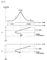
ここで、図13は、フォーカスレンズ33のレンズ駆動速度V1aと、静音下限レンズ移動速度V0bとの関係を説明するためのグラフであり、縦軸をレンズ駆動速度、横軸を像面移動係数Kとしたグラフである。図13において横軸に示すように、像面移動係数Kは、フォーカスレンズ33のレンズ位置に応じて変化するものであり、図13に示す例においては、至近側ほど像面移動係数Kは小さくなり、無限遠側ほど像面移動係数Kが大きくなるような傾向となっている。これに対し、本実施形態においては、焦点検出動作実行時において、フォーカスレンズ33を駆動させる際には、像面の移動速度が一定となるような速度にて駆動させるため、そのため、図13に示すように、フォーカスレンズ33の実際の駆動速度V1aは、フォーカスレンズ33のレンズ位置に応じて変化することとなる。すなわち、図13に示す例においては、像面の移動速度が一定の速度となるようにフォーカスレンズ33を駆動させた場合、フォーカスレンズ33のレンズ移動速度V1aは至近側ほど遅くなり、無限遠側ほど速くなる。   Here, FIG. 13 is a graph for explaining the relationship between the lens driving speed V1a of the focus lens 33 and the silent lower limit lens moving speed V0b. The vertical axis represents the lens driving speed, and the horizontal axis represents the image plane movement coefficient K. It is a graph. As shown by the horizontal axis in FIG. 13, the image plane movement coefficient K changes according to the lens position of the focus lens 33. In the example shown in FIG. Therefore, the image plane movement coefficient K tends to increase toward the infinity side. On the other hand, in the present embodiment, when the focus lens 33 is driven during the focus detection operation, the focus lens 33 is driven at a speed at which the moving speed of the image plane is constant. As shown, the actual driving speed V1a of the focus lens 33 changes according to the lens position of the focus lens 33. That is, in the example shown in FIG. 13, when the focus lens 33 is driven so that the moving speed of the image plane becomes a constant speed, the lens moving speed V1a of the focus lens 33 becomes slower toward the infinity side and becomes the infinity side. It gets faster.

その一方で、図13に示すように、フォーカスレンズ33を駆動させた場合に、このような場合における像面移動速度を示すと、図15に示すように、一定なものとなる。なお、図15は、フォーカスレンズ33の駆動による像面移動速度V1aと、静音下限像面移動速度V0b_maxとの関係を説明するためのグラフであり、縦軸を像面移動速度、横軸を像面移動係数Kとしたグラフである。また、図13、図15中においては、フォーカスレンズ33の実際の駆動速度およびフォーカスレンズ33の駆動による像面移動速度を、ともにV1aで表した。そのため、V1aは、図13に示すように、グラフの縦軸がフォーカスレンズ33の実際の駆動速度である場合には可変(横軸と平行でない)となり、図15に示すように、グラフの縦軸が像面移動速度である場合には、一定値(横軸と平行)となる。   On the other hand, when the focus lens 33 is driven as shown in FIG. 13, the image plane moving speed in such a case is constant as shown in FIG. FIG. 15 is a graph for explaining the relationship between the image plane moving speed V1a driven by the focus lens 33 and the silent lower limit image plane moving speed V0b_max. The vertical axis represents the image plane moving speed, and the horizontal axis represents the image. It is a graph made into the surface movement coefficient K. In FIG. 13 and FIG. 15, the actual driving speed of the focus lens 33 and the image plane moving speed by driving the focus lens 33 are both represented by V1a. Therefore, V1a is variable (not parallel to the horizontal axis) when the vertical axis of the graph is the actual driving speed of the focus lens 33 as shown in FIG. 13, and the vertical axis of the graph is shown in FIG. When the axis is the image plane moving speed, the value is constant (parallel to the horizontal axis).

そして、像面の移動速度が一定の速度となるように、フォーカスレンズ33を駆動させた場合に、クリップ動作を行わないと、図13に示す例のように、フォーカスレンズ33のレンズ駆動速度V1aが、静音下限レンズ移動速度V0b未満となる場合がある。たとえば、最小像面移動係数Kminが得られるフォーカスレンズ33の位置(図13において最小像面移動係数Kmin=100)において、レンズ移動速度V1aは、静音下限レンズ移動速度V0b未満となってしまう。 Then, when the focus lens 33 is driven so that the moving speed of the image plane becomes a constant speed, if the clipping operation is not performed, the lens driving speed V1a of the focus lens 33 is obtained as in the example shown in FIG. However, there are cases where the lower limit lens moving speed V0b is less than the silent minimum. For example, at the position of the focus lens 33 where the minimum image plane movement coefficient K min is obtained (the minimum image plane movement coefficient K min = 100 in FIG. 13), the lens movement speed V1a is less than the silent lower limit lens movement speed V0b. .

特に、レンズ鏡筒3の焦点距離が長い場合や光環境が明るい場合に、フォーカスレンズ33のレンズ移動速度V1aが静音下限レンズ移動速度V0b未満となりやすい。このような場合、レンズ制御部37は、クリップ動作を行うことで、図13に示すように、フォーカスレンズ33の駆動速度V1aを静音下限レンズ移動速度V0bで制限する(静音下限レンズ移動速度V0bよりも低速にならないように制御する)ことができ(ステップS304)、これにより、フォーカスレンズ33の駆動音を抑制することができる。   In particular, when the focal length of the lens barrel 3 is long or the light environment is bright, the lens moving speed V1a of the focus lens 33 tends to be less than the silent lower limit lens moving speed V0b. In such a case, the lens control unit 37 performs the clipping operation to limit the driving speed V1a of the focus lens 33 with the silent lower limit lens moving speed V0b as shown in FIG. 13 (from the silent lower limit lens moving speed V0b). (Step S304), and thus the driving sound of the focus lens 33 can be suppressed.

次に、図14を参照して、図12に示すクリップ動作を許可するか、禁止するかを決定するクリップ動作制御処理を説明する。図14は、本実施形態に係るクリップ動作制御処理を示すフローチャートである。なお、以下に説明するクリップ動作制御処理は、たとえばAF−Fモードや動画撮影モードが設定された際に、カメラ本体2により実行される。   Next, a clip operation control process for determining whether to permit or prohibit the clip operation shown in FIG. 12 will be described with reference to FIG. FIG. 14 is a flowchart showing clip operation control processing according to the present embodiment. Note that the clip operation control process described below is executed by the camera body 2 when, for example, the AF-F mode or the moving image shooting mode is set.

まず、ステップS401では、カメラ制御部21により、レンズ情報の取得が行われる。具体的には、カメラ制御部21は、ホットライン通信により、現在像面移動係数Kcur、最小像面移動係数Kmin、最大像面移動係数Kmax、および静音下限レンズ移動速度V0bをレンズ鏡筒3から取得する。 First, in step S401, the camera control unit 21 acquires lens information. Specifically, the camera control unit 21 sets the current image plane movement coefficient K cur , the minimum image plane movement coefficient K min , the maximum image plane movement coefficient K max , and the silent lower limit lens movement speed V0b through the hotline communication. Obtained from the cylinder 3.

そして、ステップS402では、カメラ制御部21により、静音下限像面移動速度V0b_maxの算出が行われる。静音下限像面移動速度V0b_maxとは、最小像面移動係数Kminが得られるフォーカスレンズ33の位置において、フォーカスレンズ33を、上述した静音下限レンズ移動速度V0bにて駆動させた際における、像面の移動速度である。以下において、静音下限像面移動速度V0b_maxについて詳細に説明する。 In step S402, the camera control unit 21 calculates the silent lower limit image plane moving speed V0b_max. The quiet lower image plane movement velocity V0b_max, at the position of the focus lens 33 to minimize image plane shift factor K min is obtained, definitive focus lens 33, when driven by the above-mentioned silent lower lens moving speed V0b, image plane Is the moving speed. Hereinafter, the silent lower limit image plane moving speed V0b_max will be described in detail.

まず、図13に示すように、フォーカスレンズ33の駆動により駆動音が発生するか否かは、フォーカスレンズ33の実際の駆動速度により決定されることとなり、そのため、図13に示すように、静音下限レンズ移動速度V0bは、レンズ駆動速度で表した場合に、一定の速度となる。その一方で、このような静音下限レンズ移動速度V0bを、像面移動速度で示すと、上述したように、像面移動係数Kは、フォーカスレンズ33のレンズ位置に応じて変化するものであるため、図15に示すように可変となる。なお、図13、図15中においては、静音下限レンズ移動速度(フォーカスレンズ33の実際の駆動速度の下限値)と、静音下限レンズ移動速度でフォーカスレンズ33を駆動させた場合の像面移動速度を、ともにV0bで表した。そのため、V0bは、図13に示すように、グラフの縦軸がフォーカスレンズ33の実際の駆動速度である場合には一定値(横軸と平行)となり、図15に示すように、グラフの縦軸が像面移動速度である場合には、可変(横軸と平行でない)となる。   First, as shown in FIG. 13, whether or not the driving sound is generated by driving the focus lens 33 is determined by the actual driving speed of the focus lens 33. Therefore, as shown in FIG. The lower limit lens moving speed V0b is a constant speed when expressed as a lens driving speed. On the other hand, when the silent lower limit lens moving speed V0b is expressed by the image plane moving speed, the image plane moving coefficient K changes according to the lens position of the focus lens 33 as described above. As shown in FIG. In FIGS. 13 and 15, the silent lower limit lens moving speed (the lower limit value of the actual driving speed of the focus lens 33) and the image plane moving speed when the focus lens 33 is driven at the silent lower limit lens moving speed. Are both represented by V0b. Therefore, V0b is a constant value (parallel to the horizontal axis) when the vertical axis of the graph is the actual driving speed of the focus lens 33 as shown in FIG. 13, and the vertical axis of the graph is shown in FIG. When the axis is the image plane moving speed, it is variable (not parallel to the horizontal axis).

そして、本実施形態では、静音下限像面移動速度V0b_maxを、像面の移動速度が一定となるようにフォーカスレンズ33を駆動させた場合に、最小像面移動係数Kminが得られるフォーカスレンズ33の位置(図15に示す例では、像面移動係数K=100)において、フォーカスレンズ33の移動速度が静音下限レンズ移動速度V0bとなる像面移動速度に設定する。すなわち、本実施形態では、静音下限レンズ移動速度にてフォーカスレンズ33を駆動させた際に、最大となる像面移動速度(図15に示す例では、像面移動係数K=100における像面移動速度)を、静音下限像面移動速度V0b_maxとして設定する。 In the present embodiment, a quiet limit image plane movement velocity V0b_max, the focus lens when the moving speed of the image plane was driven focus lens 33 to be constant, the minimum image plane shift factor K min is obtained 33 (In the example shown in FIG. 15, the image plane movement coefficient K = 100), the moving speed of the focus lens 33 is set to the image plane moving speed at which the silent lower limit lens moving speed V0b is obtained. That is, in the present embodiment, when the focus lens 33 is driven at the silent lower limit lens moving speed, the maximum image plane moving speed (in the example shown in FIG. 15, the image plane moving at the image plane moving coefficient K = 100). Speed) is set as the silent lower limit image plane moving speed V0b_max.

このように、本実施形態では、フォーカスレンズ33のレンズ位置に応じて変化する、静音下限レンズ移動速度V0bに対応する像面移動速度のうち、最大の像面移動速度(像面移動係数が最小となるレンズ位置における像面移動速度)を、静音下限像面移動速度V0b_maxとして算出する。たとえば、図15に示す例において、最小像面移動係数Kminが「100」であるため、像面移動係数が「100」となるフォーカスレンズ33のレンズ位置における像面移動速度を、静音下限像面移動速度V0b_maxとして算出する。 As described above, in the present embodiment, the maximum image plane movement speed (the image plane movement coefficient is the minimum) among the image plane movement speeds corresponding to the silent lower limit lens movement speed V0b, which changes according to the lens position of the focus lens 33. Is calculated as a silent lower limit image plane moving speed V0b_max. For example, in the example shown in FIG. 15, since the minimum image plane movement coefficient K min is “100”, the image plane movement speed at the lens position of the focus lens 33 where the image plane movement coefficient is “100” is set as the silent lower limit image. Calculated as the surface moving speed V0b_max.

具体的には、カメラ制御部21は、下記式に示すように、静音下限レンズ移動速度V0b(単位:パルス/秒)と最小像面移動係数Kmin(単位:パルス/mm)とに基づいて、静音下限像面移動速度V0b_max(単位:mm/秒)を算出する。
静音下限像面移動速度V0b_max=静音下限レンズ移動速度(フォーカスレンズの実際の駆動速度)V0b/最小像面移動係数Kmin
Specifically, the camera control unit 21, as shown in the following formula, quiet lower lens moving speed V0b (unit: pulse / s) minimum image plane shift factor and K min (unit: pulse / mm) on the basis of the The silent lower limit image plane moving speed V0b_max (unit: mm / second) is calculated.
(Actual driving speed of the focus lens) V0b / Min image plane shift factor K min silent lower image plane movement velocity V0b_max = silent lower lens moving speed

このように、本実施形態では、最小像面移動係数Kminを用いて、静音下限像面移動速度V0b_maxを算出することで、AF−Fによる焦点検出や動画撮影を開始したタイミングで、静音下限像面移動速度V0b_maxを算出することができる。たとえば、図15に示す例において、AF−Fによる焦点検出または動画撮影をタイミングt1’において開始した場合に、このタイミングt1’において、像面移動係数Kが「100」となるフォーカスレンズ33のレンズ位置における像面移動速度を、静音下限像面移動速度V0b_maxとして算出することができる。 Thus, in the present embodiment, by using the minimum image plane shift factor K min, by calculating the quiet lower image plane movement velocity V0b_max, at the timing of starting the focus detection and video recording by AF-F, quiet limit The image plane moving speed V0b_max can be calculated. For example, in the example shown in FIG. 15, when focus detection or moving image shooting by AF-F is started at timing t1 ′, the lens of the focus lens 33 whose image plane movement coefficient K is “100” at timing t1 ′. The image plane moving speed at the position can be calculated as the silent lower limit image plane moving speed V0b_max.

次いで、ステップS403では、カメラ制御部21により、ステップS401で取得した焦点検出用の像面移動速度V1aと、ステップS402で算出した静音下限像面移動速度V0b_maxとの比較が行われる。具体的には、カメラ制御部21は、焦点検出用の像面移動速度V1a(単位:mm/秒)と静音下限像面移動速度V0b_max(単位:mm/秒)とが、下記式を満たすか否かを判断する。
(焦点検出用の像面移動速度V1a×Kc)>静音下限像面移動速度V0b_max
なお、上記式中、係数Kcは1以上の値(Kc≧1)であり、その詳細については後述する。
Next, in step S403, the camera control unit 21 compares the image plane moving speed V1a for focus detection acquired in step S401 with the silent lower limit image plane moving speed V0b_max calculated in step S402. Specifically, the camera control unit 21 determines whether the image plane moving speed V1a (unit: mm / sec) for focus detection and the silent lower limit image plane moving speed V0b_max (unit: mm / sec) satisfy the following expression: Judge whether or not.
(Focus detection image plane moving speed V1a × Kc)> Silent lower limit image plane moving speed V0b_max
In the above formula, the coefficient Kc is a value of 1 or more (Kc ≧ 1), and details thereof will be described later.

上記式を満たす場合には、ステップS404に進み、カメラ制御部21により、図12に示すクリップ動作が許可される。すなわち、フォーカスレンズ33の駆動音を抑制するために、図13に示すように、フォーカスレンズ33の駆動速度V1aが静音下限レンズ移動速度V0bに制限される(フォーカスレンズ33の駆動速度V1aが静音下限レンズ移動速度V0bよりも低い速度にならないように探索制御が行われる。)。   If the above equation is satisfied, the process proceeds to step S404, and the clip operation shown in FIG. That is, in order to suppress the drive sound of the focus lens 33, as shown in FIG. 13, the drive speed V1a of the focus lens 33 is limited to the silent lower limit lens moving speed V0b (the drive speed V1a of the focus lens 33 is lower than the silent lower limit). Search control is performed so as not to be lower than the lens moving speed V0b.)

一方、上記式を満たさない場合には、ステップS405に進み、図12に示すクリップ動作が禁止される。すなわち、フォーカスレンズ33の駆動速度V1aを静音下限レンズ移動速度V0bで制限せずに(フォーカスレンズ33の駆動速度V1aが静音下限レンズ移動速度V0bよりも低い速度となることを許容し)、合焦位置を適切に検出することができる像面移動速度V1aとなるように、フォーカスレンズ33を駆動させる。   On the other hand, if the above equation is not satisfied, the process proceeds to step S405, and the clip operation shown in FIG. 12 is prohibited. That is, the focusing speed is not limited by the silent lower limit lens moving speed V0b (the driving speed V1a of the focusing lens 33 is allowed to be lower than the silent lower limit lens moving speed V0b). The focus lens 33 is driven so that the image plane moving speed V1a can be detected appropriately.

ここで、図13に示すように、クリップ動作を許可して、フォーカスレンズ33の駆動速度を、静音下限レンズ移動速度V0bで制限してしまうと、像面移動係数Kが小さいレンズ位置において像面の移動速度が速くなってしまい、その結果、像面の移動速度が、合焦位置を適切に検出できる像面移動速度よりも速くなり、適切な合焦精度が得られない場合がある。一方、クリップ動作を禁止して、像面の移動速度が合焦位置を適切に検出できる像面移動速度となるように、フォーカスレンズ33を駆動させた場合には、図13に示すように、フォーカスレンズ33の駆動速度V1aが静音下限レンズ移動速度V0b未満となり、所定値以上の駆動音が発生してしまう場合がある。   Here, as shown in FIG. 13, if the clip operation is permitted and the driving speed of the focus lens 33 is limited by the silent lower limit lens moving speed V0b, the image plane is at a lens position where the image plane moving coefficient K is small. As a result, the moving speed of the image plane becomes faster than the moving speed of the image plane that can appropriately detect the in-focus position, and appropriate focusing accuracy may not be obtained. On the other hand, when the clipping lens is prohibited and the focus lens 33 is driven so that the moving speed of the image plane becomes an image plane moving speed at which the in-focus position can be appropriately detected, as shown in FIG. The driving speed V1a of the focus lens 33 becomes lower than the silent lower limit lens moving speed V0b, and a driving sound of a predetermined value or more may be generated.

このように、焦点検出用の像面移動速度V1aが静音下限像面移動速度V0b_max未満となる場合には、合焦位置を適切に検出できる像面移動速度V1aが得られるように、フォーカスレンズ33を静音下限レンズ移動速度V0b未満のレンズ駆動速度で駆動させるか、フォーカスレンズ33の駆動音を抑制するために、フォーカスレンズ33を静音下限レンズ移動速度V0b以上のレンズ駆動速度で駆動させるかが問題となる場合がある。   As described above, when the image plane moving speed V1a for focus detection is less than the silent lower limit image plane moving speed V0b_max, the focus lens 33 is obtained so that the image plane moving speed V1a that can appropriately detect the in-focus position is obtained. Is driven at a lens driving speed less than the silent lower limit lens moving speed V0b, or in order to suppress the driving sound of the focus lens 33, the focus lens 33 is driven at a lens driving speed equal to or higher than the silent lower limit lens moving speed V0b. It may become.

これに対して、本実施形態では、上記式における係数Kcを、フォーカスレンズ33を静音下限レンズ移動速度V0bで駆動させた場合でも、上記式を満たす場合には、一定の焦点検出精度を確保できる1以上の値として記憶しておく。これにより、カメラ制御部21は、図15に示すように、焦点検出用の像面移動速度V1aが静音下限像面移動速度V0b_max未満となる場合でも、上記式を満たす場合には、一定の焦点検出精度を確保できるものと判断し、フォーカスレンズ33の駆動音の抑制を優先して、フォーカスレンズ33を静音下限レンズ移動速度V0b未満のレンズ駆動速度で駆動させるクリップ動作を許可する。   On the other hand, in this embodiment, even when the coefficient Kc in the above equation satisfies the above equation even when the focus lens 33 is driven at the silent lower limit lens moving speed V0b, a certain focus detection accuracy can be ensured. It is stored as a value of 1 or more. As a result, as shown in FIG. 15, the camera control unit 21 maintains a constant focus when the above expression is satisfied even when the focus detection image plane moving speed V1a is less than the silent lower limit image plane moving speed V0b_max. It is determined that the detection accuracy can be ensured, and the clip operation for driving the focus lens 33 at a lens driving speed lower than the silent lower limit lens moving speed V0b is permitted with priority given to the suppression of the driving sound of the focus lens 33.

一方、仮に、焦点検出時の像面移動速度V1a×Kc(但し、Kc≧1)が静音下限像面移動速度V0b_max以下となる場合に、クリップ動作を許可し、フォーカスレンズ33の駆動速度を静音下限レンズ移動速度V0bで制限した場合には、焦点検出用の像面移動速度が速くなり過ぎてしまい、焦点検出精度を確保することができない場合がある。そのため、カメラ制御部21は、上記式を満たさない場合には、焦点検出精度を優先して、図12に示すクリップ動作を禁止する。これにより、焦点検出時に、像面の移動速度を、合焦位置を適切に検出することができる像面移動速度V1aとすることができ、焦点検出を高い精度で行うことができる。   On the other hand, if the image plane moving speed V1a × Kc (Kc ≧ 1) at the time of focus detection is equal to or lower than the silent lower limit image plane moving speed V0b_max, the clipping operation is permitted and the driving speed of the focus lens 33 is set to silent. When limited by the lower limit lens moving speed V0b, the image plane moving speed for focus detection becomes too fast, and the focus detection accuracy may not be ensured. Therefore, when the above formula is not satisfied, the camera control unit 21 prioritizes focus detection accuracy and prohibits the clip operation shown in FIG. Thereby, at the time of focus detection, the moving speed of the image plane can be set to the image plane moving speed V1a that can appropriately detect the in-focus position, and the focus detection can be performed with high accuracy.

なお、絞り値が大きい(絞り開口が小さい)場合には、被写界深度が深くなるため、合焦位置を適切に検出することができるサンプリング間隔は広くなる。その結果、合焦位置を適切に検出することができる像面移動速度V1aを速くすることができる。そのため、合焦位置を適切に検出することができる像面移動速度V1aが固定の値である場合には、カメラ制御部21は、絞り値が大きいほど、上記式の係数Kcを大きくすることができる。   When the aperture value is large (diaphragm aperture is small), the depth of field becomes deep, and the sampling interval at which the in-focus position can be appropriately detected becomes wide. As a result, it is possible to increase the image plane moving speed V1a at which the in-focus position can be detected appropriately. Therefore, when the image plane moving speed V1a at which the in-focus position can be appropriately detected is a fixed value, the camera control unit 21 may increase the coefficient Kc of the above formula as the aperture value increases. it can.

同様に、ライブビュー画像など画像サイズが小さい場合(画像の圧縮率が高い場合、あるいは画素データの間引き率が高い場合)には、高い焦点検出精度が要求されないため、上記式の係数Kcを大きくすることができる。また、撮像素子22における画素ピッチが広い場合なども、上記式の係数Kcを大きくすることができる。   Similarly, when the image size is small (such as when the image compression rate is high or the pixel data thinning rate is high) such as a live view image, high focus detection accuracy is not required, so the coefficient Kc in the above equation is increased. can do. Further, the coefficient Kc in the above equation can be increased also when the pixel pitch in the image sensor 22 is wide.

次に、図16および図17を参照して、クリップ動作の制御についてより詳細に説明する。図16は、焦点検出時の像面の移動速度V1aと、クリップ動作との関係を示す図であり、図17は、フォーカスレンズ33の実際のレンズ駆動速度V1aと、クリップ動作との関係を説明するための図である。   Next, with reference to FIGS. 16 and 17, the control of the clip operation will be described in more detail. FIG. 16 is a diagram illustrating the relationship between the moving speed V1a of the image plane at the time of focus detection and the clipping operation, and FIG. 17 illustrates the relationship between the actual lens driving speed V1a of the focus lens 33 and the clipping operation. It is a figure for doing.

たとえば、上述したように、本実施形態では、レリーズスイッチの半押しをトリガとして探索制御を開始する場合とレリーズスイッチの半押し以外の条件をトリガとして探索制御を開始する場合、静止画撮影モードと動画撮影モード、スポーツ撮影モードと風景撮影モード、あるいは、焦点距離、撮影距離、絞り値等に応じて、探索制御における像面の移動速度が異なる場合がある。図16では、このような異なる3つの像面の移動速度V1a_1,V1a_2,V1a_3を例示している。   For example, as described above, in this embodiment, when the search control is started with a half-press of the release switch as a trigger, and when the search control is started with a condition other than the half-press of the release switch as a trigger, The moving speed of the image plane in the search control may differ depending on the moving image shooting mode, the sports shooting mode and the landscape shooting mode, or the focal length, shooting distance, aperture value, and the like. FIG. 16 illustrates the moving speeds V1a_1, V1a_2, and V1a_3 of three different image planes.

具体的には、図16に示す焦点検出時の像面移動速度V1a_1は、焦点状態を適切に検出できる像面の移動速度のうち最大の移動速度であり、上記式の関係を満たす像面の移動速度である。また、焦点検出時の像面移動速度V1a_2は、V1a_1よりも遅い像面の移動速度であるが、タイミングt1’において上記式の関係を満たす像面の移動速度である。一方、焦点検出時の像面移動速度V1a_3は、上記式の関係を満たさない像面の移動速度である。   Specifically, the image plane moving speed V1a_1 at the time of focus detection shown in FIG. 16 is the maximum moving speed among the moving speeds of the image plane that can appropriately detect the focus state, and the image plane that satisfies the relationship of the above formula. It is the moving speed. The image plane moving speed V1a_2 at the time of focus detection is an image plane moving speed that is slower than V1a_1, but is an image plane moving speed that satisfies the relationship of the above formula at timing t1 '. On the other hand, the image plane moving speed V1a_3 at the time of focus detection is an image plane moving speed that does not satisfy the relationship of the above formula.

このように、図16に示す例において、焦点検出時の像面の移動速度がV1a_1およびV1a_2である場合には、タイミングt1において上記式の関係を満たすため、図16に示すクリップ動作が許可される。一方、焦点検出時の像面の移動速度がV1a_3である場合には、上記式の関係を満たさないため、図12に示すクリップ動作は禁止される。   As described above, in the example shown in FIG. 16, when the moving speed of the image plane at the time of focus detection is V1a_1 and V1a_2, the clip operation shown in FIG. The On the other hand, when the moving speed of the image plane at the time of focus detection is V1a_3, the clip operation shown in FIG.

この点について、図17を参照して、具体的に説明する。なお、図17は、図16に示すグラフの縦軸を、像面移動速度からレンズ駆動速度に変更して示した図である。上述したように、フォーカスレンズ33のレンズ駆動速度V1a_1は、上記式(3)の関係を満たすため、クリップ動作が許可される。しかしながら、図17に示すように、最小像面移動係数(K=100)が得られるレンズ位置においても、レンズ駆動速度V1a_1は静音下限レンズ移動速度V0b未満とはならないために、実際には、クリップ動作は行われない。   This point will be specifically described with reference to FIG. FIG. 17 is a diagram in which the vertical axis of the graph shown in FIG. 16 is changed from the image plane moving speed to the lens driving speed. As described above, since the lens driving speed V1a_1 of the focus lens 33 satisfies the relationship of the above formula (3), the clipping operation is permitted. However, as shown in FIG. 17, even at the lens position where the minimum image plane movement coefficient (K = 100) is obtained, the lens driving speed V1a_1 is not less than the silent lower limit lens moving speed V0b. No action is taken.

また、フォーカスレンズ33のレンズ駆動速度V1a_2も、焦点検出の開始タイミングであるタイミングt1’において上記式の関係を満たすため、クリップ動作が許可される。図17に示す例では、フォーカスレンズ33をレンズ駆動速度V1a_2で駆動させた場合に、像面移動係数KがK1となるレンズ位置において、レンズ駆動速度V1a_2が静音下限レンズ移動速度V0b未満となるため、K1よりも像面移動係数Kが小さいレンズ位置において、フォーカスレンズ33のレンズ駆動速度V1a_2が静音下限レンズ移動速度V0bで制限される。   Further, since the lens driving speed V1a_2 of the focus lens 33 also satisfies the relationship of the above formula at the timing t1 ′ that is the focus detection start timing, the clipping operation is permitted. In the example shown in FIG. 17, when the focus lens 33 is driven at the lens driving speed V1a_2, the lens driving speed V1a_2 is less than the silent lower limit lens moving speed V0b at the lens position where the image plane movement coefficient K is K1. , The lens driving speed V1a_2 of the focus lens 33 is limited by the silent lower limit lens moving speed V0b at the lens position where the image plane movement coefficient K is smaller than K1.

すなわち、フォーカスレンズ33のレンズ駆動速度V1a_2が静音下限レンズ移動速度V0b未満となるレンズ位置において、クリップ動作が行われ、これにより、焦点検出時の像面の移動速度V1a_2は、それまでの像面の移動速度(探索速度)とは異なる像面の移動速度で、焦点評価値の探索制御を行うこととなる。すなわち、図16に示すように、像面移動係数がK1よりも小さくなるレンズ位置において、焦点検出時の像面の移動速度V1a_2が今までの一定の速度とは異なる速度となる。   That is, the clipping operation is performed at the lens position where the lens driving speed V1a_2 of the focus lens 33 is less than the silent lower limit lens moving speed V0b, whereby the moving speed V1a_2 of the image plane at the time of focus detection is The focus evaluation value search control is performed at a moving speed of the image plane different from the moving speed (search speed). That is, as shown in FIG. 16, at the lens position where the image plane movement coefficient is smaller than K1, the image plane moving speed V1a_2 at the time of focus detection is different from the constant speed so far.

また、フォーカスレンズ33のレンズ駆動速度V1a_3は、上記式の関係を満たさないため、クリップ動作が禁止される。そのため、図17に示す例では、フォーカスレンズ33をレンズ駆動速度V1a_3で駆動させた場合に、像面移動係数KがK2となるレンズ位置において、レンズ駆動速度V1a_3は静音下限レンズ移動速度V0b未満となるが、K2よりも小さい像面移動係数Kが得られるレンズ位置において、クリップ動作が行われず、焦点状態を適切に検出するために、フォーカスレンズ33の駆動速度V1a_3が静音下限レンズ移動速度V0b未満となってもクリップ動作が行われないこととなる。   Further, since the lens drive speed V1a_3 of the focus lens 33 does not satisfy the relationship of the above formula, the clip operation is prohibited. Therefore, in the example shown in FIG. 17, when the focus lens 33 is driven at the lens driving speed V1a_3, the lens driving speed V1a_3 is less than the silent lower limit lens moving speed V0b at the lens position where the image plane movement coefficient K is K2. However, at the lens position where an image plane movement coefficient K smaller than K2 is obtained, the clipping operation is not performed, and the driving speed V1a_3 of the focus lens 33 is less than the silent lower limit lens moving speed V0b in order to appropriately detect the focus state. In this case, the clip operation is not performed.

以上のように、第4実施形態では、静音下限レンズ移動速度V0bでフォーカスレンズ33を駆動させた場合における像面移動速度のうち、最大の像面移動速度を静音下限像面移動速度V0b_maxとして算出し、算出した静音下限像面移動速度V0b_maxと焦点検出時の像面の移動速度V1aとを比較する。そして、焦点検出時の像面の移動速度V1a×Kc(但し、Kc≧1)が静音下限像面移動速度V0b_maxよりも速い場合には、フォーカスレンズ33を静音下限レンズ移動速度V0bで駆動させた場合でも、一定以上の焦点検出精度が得られるものと判断し、図12に示すクリップ動作を許可する。これにより、本実施形態では、焦点検出精度を確保しながら、フォーカスレンズ33の駆動音を抑制することができる。   As described above, in the fourth embodiment, the maximum image plane moving speed among the image plane moving speeds when the focus lens 33 is driven at the silent lower limit lens moving speed V0b is calculated as the silent lower limit image plane moving speed V0b_max. Then, the calculated silent lower limit image plane moving speed V0b_max is compared with the image plane moving speed V1a at the time of focus detection. When the image plane moving speed V1a × Kc (where Kc ≧ 1) at the time of focus detection is faster than the silent lower limit image plane moving speed V0b_max, the focus lens 33 is driven at the silent lower limit lens moving speed V0b. Even in this case, it is determined that the focus detection accuracy of a certain level or more is obtained, and the clip operation shown in FIG. Thereby, in this embodiment, the drive sound of the focus lens 33 can be suppressed while ensuring focus detection accuracy.

一方、焦点検出時の像面の移動速度V1a×Kc(但し、Kc≧1)が静音下限像面移動速度V0b_max以下となる場合に、フォーカスレンズ33の駆動速度V1aを静音下限レンズ移動速度V0bで制限した場合には、適切な焦点検出精度が得られない場合がある。そのため、本実施形態では、このような場合には、焦点検出に適した像面移動速度が得られるように、図12に示すクリップ動作を禁止する。これにより、本実施形態では、焦点検出時に合焦位置を適切に検出することができる。   On the other hand, when the image plane moving speed V1a × Kc (where Kc ≧ 1) at the time of focus detection is equal to or lower than the silent lower limit image plane moving speed V0b_max, the driving speed V1a of the focus lens 33 is set to the silent lower limit lens moving speed V0b. If limited, appropriate focus detection accuracy may not be obtained. Therefore, in this embodiment, in such a case, the clip operation shown in FIG. 12 is prohibited so that an image plane moving speed suitable for focus detection can be obtained. Thereby, in this embodiment, a focus position can be detected appropriately at the time of focus detection.

また、本実施形態では、レンズ鏡筒3のレンズメモリ38に最小像面移動係数Kminを予め記憶しており、この最小像面移動係数Kminを用いて、静音下限像面移動速度V0b_maxを算出する。そのため、本実施形態では、たとえば、図10に示すように、動画撮影やAF−Fモードによる焦点検出が開始された時刻t1のタイミングで、焦点検出用の像面移動速度V1a×Kc(但し、Kc≧1)が静音下限像面移動速度V0b_maxを超えるか否かを判断し、クリップ動作を行うか否かを判断することができる。このように、本実施形態では、現在位置像面移動係数Kcurを用いて、クリップ動作を行うか否かを繰り返し判断するのではなく、最小像面移動係数Kminを用いて、動画撮影やAF−Fモードによる焦点検出が開始された最初のタイミングで、クリップ動作を行うか否かを判断することができるため、カメラ本体2の処理負荷を軽減することができる。 In the present embodiment, the minimum image plane movement coefficient K min is stored in advance in the lens memory 38 of the lens barrel 3, and the silent lower limit image plane movement speed V0b_max is set using the minimum image plane movement coefficient K min. calculate. Therefore, in the present embodiment, for example, as shown in FIG. 10, at the time t1 when the focus detection in the moving image shooting or the AF-F mode is started, the image plane moving speed V1a × Kc for focus detection (however, It is possible to determine whether or not the clip operation is performed by determining whether or not Kc ≧ 1) exceeds the silent lower limit image plane moving speed V0b_max. As described above, in this embodiment, the current position image plane movement coefficient K cur is not used to repeatedly determine whether or not to perform the clip operation, but the minimum image plane movement coefficient K min is used to record a moving image. Since it is possible to determine whether or not to perform the clip operation at the first timing when focus detection in the AF-F mode is started, the processing load on the camera body 2 can be reduced.

なお、上述した実施形態においては、図12に示すクリップ動作制御処理を、カメラ本体2において実行する構成を例示したが、この構成に限定されず、たとえば、図7に示すクリップ動作制御処理を、レンズ鏡筒3において実行する構成としてもよい。   In the above-described embodiment, the configuration in which the clip operation control process illustrated in FIG. 12 is executed in the camera body 2 is exemplified. However, the configuration is not limited to this configuration. For example, the clip operation control process illustrated in FIG. It is good also as a structure performed in the lens-barrel 3. FIG.

また、上述した実施形態では、上記式に示すように、像面移動係数Kを、像面移動係数K=(フォーカスレンズ33の駆動量/像面の移動量)で算出する構成を例示したが、この構成に限定されず、たとえば、下記式に示すように算出する構成としてもよい。
像面移動係数K=(像面の移動量/フォーカスレンズ33の駆動量)
なお、この場合、カメラ制御部21は、静音下限像面移動速度V0b_maxを以下のように算出することができる。すなわち、カメラ制御部21は、下記式に示すように、静音下限レンズ移動速度V0b(単位:パルス/秒)と、ズームレンズ32の各レンズ位置(焦点距離)における像面移動係数Kのうち、最大となる値を示す最大像面移動係数Kmax(単位:パルス/mm)とに基づいて、静音下限像面移動速度V0b_max(単位:mm/秒)を算出することができる。
静音下限像面移動速度V0b_max=静音下限レンズ移動速度V0b/最大像面移動係数Kmax
In the above-described embodiment, as illustrated in the above formula, the configuration in which the image plane movement coefficient K is calculated by the image plane movement coefficient K = (drive amount of the focus lens 33 / image plane movement amount) is exemplified. However, the present invention is not limited to this configuration, and for example, a configuration for calculation as shown in the following formula may be adopted.
Image plane movement coefficient K = (Movement amount of image plane / drive amount of focus lens 33)
In this case, the camera control unit 21 can calculate the silent lower limit image plane moving speed V0b_max as follows. That is, as shown in the following equation, the camera control unit 21 includes the silent lower limit lens moving speed V0b (unit: pulses / second) and the image plane movement coefficient K at each lens position (focal length) of the zoom lens 32. The silent lower limit image plane moving speed V0b_max (unit: mm / second) can be calculated based on the maximum image plane movement coefficient K max (unit: pulse / mm) indicating the maximum value.
Silent lower image plane movement velocity V0b_max = silent lower lens moving speed V0b / maximum image plane shift factor K max

例えば、像面移動係数Kとして、「像面の移動量/フォーカスレンズ33の駆動量」で算出される値を採用した場合には、値(絶対値)が大きくなるほど、フォーカスレンズが所定値(例えば1mm)駆動した場合の像面の移動量が大きくなる。像面移動係数Kとして、「フォーカスレンズ33の駆動量/像面の移動量」で算出される値を採用した場合には、値(絶対値)が大きくなるほど、フォーカスレンズが所定値(例えば1mm)駆動した場合の像面の移動量が小さくなる。   For example, when the value calculated by “the amount of movement of the image plane / the amount of drive of the focus lens 33” is used as the image plane movement coefficient K, the larger the value (absolute value), the larger the value of the focus lens (the predetermined value ( For example, the amount of movement of the image plane when driving is increased. When the value calculated by “the driving amount of the focus lens 33 / the moving amount of the image plane” is adopted as the image plane movement coefficient K, the larger the value (absolute value), the larger the value of the focus lens (for example, 1 mm). ) The amount of movement of the image plane when driven becomes small.

また、上述した実施形態に加えて、フォーカスレンズ33の駆動音を抑制する静音モードが設定されている場合に、上述したクリップ動作およびクリップ動作制御処理を実行し、静音モードが設定されていない場合には、上述したクリップ動作およびクリップ動作制御処理を実行しない構成としてもよい。また、静音モードが設定されている場合は、フォーカスレンズ33の駆動音の抑制を優先し、図14に示すクリップ動作制御処理を行わずに、図12に示すクリップ動作を常に行う構成としてもよい。
また、上述した実施例においては、像面移動係数K=(フォーカスレンズ33の駆動量/像面の移動量)として説明したが、これに限定されるものではない。例えば、像面移動係数K=(像面の移動量/フォーカスレンズ33の駆動量)のように定義した場合、最大像面移動係数Kmaxを用いて、上述した実施例と同様にクリップ動作等の制御をすることができる。
In addition to the above-described embodiment, when the silent mode for suppressing the driving sound of the focus lens 33 is set, the above-described clipping operation and the clipping operation control process are executed, and the silent mode is not set. Alternatively, the clip operation and the clip operation control process described above may not be executed. Further, when the silent mode is set, priority may be given to suppression of the driving sound of the focus lens 33, and the clip operation shown in FIG. 12 may be always performed without performing the clip operation control process shown in FIG. .
In the above-described embodiments, the image plane movement coefficient K = (drive amount of the focus lens 33 / movement amount of the image plane) has been described. However, the present invention is not limited to this. For example, when the image plane movement coefficient K = (image plane movement amount / focus lens 33 drive amount) is defined, the maximum image plane movement coefficient K max is used to perform a clip operation or the like in the above-described embodiment. Can be controlled.

《第5実施形態》
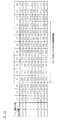
次いで、本発明の第5実施形態について説明する。第5実施形態では、以下の点において異なる以外は、上述した第1実施形態と同様の構成を有するものである。図18に、第5実施形態において用いられる、ズームレンズ32のレンズ位置(焦点距離)およびフォーカスレンズ33のレンズ位置(撮影距離)と、像面移動係数Kとの関係を示すテーブルを示す。5
<< 5th Embodiment >>
Next, a fifth embodiment of the present invention will be described. The fifth embodiment has the same configuration as that of the first embodiment described above except that the following points are different. FIG. 18 shows a table showing the relationship between the lens position (focal length) of the zoom lens 32 and the lens position (shooting distance) of the focus lens 33 and the image plane movement coefficient K used in the fifth embodiment. 5

すなわち、第5実施形態においては、図3に示す最も至近側の領域である「D1」よりも、さらに至近側の領域である「D0」、「X1」、「X2」領域が備えられている。また、同様に、図3に示す最も無限遠側の領域である「D9」よりも、さらに無限遠側の領域である「D10」、「X3」、「X4」領域が備えられている。なお、以下においては、まず、このような、さらに至近側の領域である「D0」、「X1」、「X2」領域、さらに無限遠側の領域である「D10」、「X3」、「X4」領域について説明する。   That is, in the fifth embodiment, “D0”, “X1”, and “X2” regions that are closer to the closest region than “D1” shown in FIG. 3 are provided. . Similarly, “D10”, “X3”, and “X4” regions, which are regions on the infinity side, are provided further than “D9” that is the region on the most infinity side shown in FIG. In the following, first, such “D0”, “X1”, “X2” regions that are closer to each other, and “D10”, “X3”, “X4” that are further closer to infinity. ”Area will be described.

ここで、図19に示すように、本実施形態においては、フォーカスレンズ33は、図中において一点鎖線で示す光軸L1上を、無限遠方向410および至近方向420に向けて移動可能に構成されている。無限遠方向410のメカ的な端点(機械的な端点)430および至近方向420のメカ的な端点440には不図示のストッパーが設けられ、フォーカスレンズ33の移動を制限する。すなわち、フォーカスレンズ33は無限遠方向410のメカ的な端点430から、至近方向420のメカ的な端点440まで移動可能に構成されている。   Here, as shown in FIG. 19, in the present embodiment, the focus lens 33 is configured to be movable in the infinity direction 410 and the closest direction 420 on the optical axis L <b> 1 indicated by a one-dot chain line in the drawing. ing. Stoppers (not shown) are provided at the mechanical end points (mechanical end points) 430 in the infinite direction 410 and the mechanical end points 440 in the closest direction 420 to restrict the movement of the focus lens 33. That is, the focus lens 33 is configured to be movable from a mechanical end point 430 in the infinity direction 410 to a mechanical end point 440 in the closest direction 420.

ただし、レンズ制御部37が実際にフォーカスレンズ33を駆動させる範囲は、上述のメカ的な端点430からメカ的な端点440までの範囲より小さい。この移動範囲について具体的に述べると、レンズ制御部37は無限遠方向410のメカ的な端点430より内側に設けられた無限ソフトリミット位置450から、至近方向420のメカ的な端点440より内側に設けられた至近ソフトリミット位置460までの範囲でフォーカスレンズ33を駆動する。すなわちレンズ駆動部212は、フォーカスレンズ33を至近側の駆動限界の位置に対応する至近ソフトリミット位置460と無限遠側の駆動限界の位置に対応する無限ソフトリミット位置450との間で駆動する。   However, the range in which the lens control unit 37 actually drives the focus lens 33 is smaller than the range from the mechanical end point 430 to the mechanical end point 440 described above. More specifically, the moving range of the lens control unit 37 is determined from the infinite soft limit position 450 provided inside the mechanical end point 430 in the infinity direction 410 to the inside of the mechanical end point 440 in the closest direction 420. The focus lens 33 is driven in the range up to the provided closest soft limit position 460. That is, the lens driving unit 212 drives the focus lens 33 between the closest soft limit position 460 corresponding to the closest drive limit position and the infinite soft limit position 450 corresponding to the infinity drive limit position.

無限ソフトリミット位置450は、無限合焦位置470より外側に設けられる。なお無限合焦位置470とは、レンズ31,32,33,34および絞り35を含む撮影光学系が合焦可能な最も無限遠側の位置に対応するフォーカスレンズ33の位置である。無限ソフトリミット位置450をこのような位置に設ける理由は、コントラスト検出方式による焦点検出を行う際に、無限合焦位置470に焦点評価値のピークが存在することがあるためである。すなわち、無限合焦位置470を無限ソフトリミット位置450に一致させてしまうと、無限合焦位置470に存在する焦点評価値のピークをピークとして認識することができないという問題があり、このような問題を避けるため、無限ソフトリミット位置450は、無限合焦位置470より外側に設けられる。同様に、至近ソフトリミット位置460は、至近合焦位置480より外側に設けられる。ここで至近合焦位置480とは、レンズ31,32,33,34および絞り35を含む撮影光学系が合焦可能な最も至近側の位置に対応するフォーカスレンズ33の位置である。   The infinite soft limit position 450 is provided outside the infinite focus position 470. The infinite focus position 470 is the position of the focus lens 33 corresponding to the position on the most infinite side where the photographing optical system including the lenses 31, 32, 33, 34 and the diaphragm 35 can be focused. The reason why the infinite soft limit position 450 is provided at such a position is that a focus evaluation value peak may exist at the infinite focus position 470 when performing focus detection by the contrast detection method. That is, if the infinite focus position 470 is matched with the infinite soft limit position 450, there is a problem that the peak of the focus evaluation value existing at the infinite focus position 470 cannot be recognized as a peak. Therefore, the infinite soft limit position 450 is provided outside the infinite focusing position 470. Similarly, the closest soft limit position 460 is provided outside the closest focus position 480. Here, the closest focus position 480 is the position of the focus lens 33 corresponding to the closest position where the photographing optical system including the lenses 31, 32, 33, 34 and the diaphragm 35 can be focused.

そして、図18に示す「D0」領域は、至近ソフトリミット位置460に対応する位置であり、「X1」、「X2」領域は、至近ソフトリミット位置よりも至近側の領域、例えば、至近方向420のメカ的な端点440に対応する位置、至近ソフトリミット位置と端点440との間の位置等である。また、図18に示す「D10」領域は、無限ソフトリミット位置450に対応する位置であり、「X3」、「X4」領域は、無限ソフトリミット位置よりも無限側の領域、例えば、無限遠方向410のメカ的な端点430に対応する位置、無限ソフトリミット位置と端点430との間の位置等である。   18 is a position corresponding to the closest soft limit position 460, and the “X1” and “X2” areas are areas closer to the closest soft limit position, for example, the closest direction 420. The position corresponding to the mechanical end point 440, the position between the closest soft limit position and the end point 440, and the like. Further, the “D10” area shown in FIG. 18 is a position corresponding to the infinite soft limit position 450, and the “X3” and “X4” areas are areas on the infinite side of the infinite soft limit position, for example, in the infinity direction. 410, a position corresponding to the mechanical end point 430, a position between the infinite soft limit position and the end point 430, and the like.

そして、本実施形態においては、これらの領域のうち、至近ソフトリミット位置460に対応する「D0」領域における像面移動係数「K10」、「K20」、・・・「K90」を、最小像面移動係数Kminに設定することができる。同様に、無限ソフトリミット位置450に対応する「D10」領域における像面移動係数「K110」、「K210」、・・・「K910」を、最大像面移動係数Kmaxに設定することができる。 In this embodiment, among these areas, the image plane movement coefficients “K10”, “K20”,... “K90” in the “D0” area corresponding to the closest soft limit position 460 are set as the minimum image plane. The movement coefficient K min can be set. Similarly, the image plane movement coefficients “K110”, “K210”,... “K910” in the “D10” region corresponding to the infinite soft limit position 450 can be set to the maximum image plane movement coefficient K max .

なお、本実施形態においては、「X1」領域における像面移動係数「α11」、「α21」、・・・「α91」の値は、「D0」領域における像面移動係数「K10」、「K20」、・・・「K90」の値よりも小さい。同様に、「X2」領域における像面移動係数「α12」、「α22」、・・・「α92」の値は、「D0」領域における像面移動係数「K10」、「K20」、・・・「K90」の値よりも小さい。また、「X3」領域における像面移動係数「α13」、「α23」、・・・「α93」の値は、「D10」領域における像面移動係数「K110」、「K210」、・・・「K910」の値よりも大きい。「X4」領域における像面移動係数「α14」、「α24」、・・・「α94」の値は、「D10」領域における像面移動係数「K110」、「K210」、・・・「k910」の値よりも大きい。   In this embodiment, the values of the image plane movement coefficients “α11”, “α21”,... “Α91” in the “X1” region are the image plane movement coefficients “K10”, “K20” in the “D0” region. ... Smaller than the value of “K90”. Similarly, the values of the image plane movement coefficients “α12”, “α22”,... “Α92” in the “X2” area are the image plane movement coefficients “K10”, “K20”,. It is smaller than the value of “K90”. In addition, the values of the image plane movement coefficients “α13”, “α23”,... “Α93” in the “X3” area are the image plane movement coefficients “K110”, “K210”,. It is larger than the value of “K910”. The values of the image plane movement coefficients “α14”, “α24”,... “Α94” in the “X4” area are the image plane movement coefficients “K110”, “K210”,... “K910” in the “D10” area. Greater than the value of.

しかしその一方で、本実施形態においては、「D0」における像面移動係数K(「K10」、「K20」、・・・「K90」)が最小像面移動係数Kminに設定され、「D10」における像面移動係数K(「K110」、「K210」・・・「K910」)が最大像面移動係数Kmaxに設定される。特に、「X1」、「X2」、「X3」、「X4」領域は、収差、メカ的機構等の事情により、フォーカスレンズ33を駆動させない、又は、フォーカスレンズ33を駆動させる必要が少ない領域である。このため、「X1」、「X2」、「X3」、「X4」領域に対応する像面移動係数「α11」、「α21」、・・・「α94」を最小像面移動係数Kminや最大像面移動係数Kmaxに設定しても適切なオートフォーカス制御(例えば、フォーカスレンズの速度制御、静音制御、ガタ詰め制御等)に寄与しないからである。 On the other hand, in the present embodiment, the image plane movement coefficient K (“K10”, “K20”,... “K90”) at “D0” is set to the minimum image plane movement coefficient K min , and “D10 The image plane movement coefficient K (“K110”, “K210”... “K910”) is set to the maximum image plane movement coefficient K max . In particular, the “X1”, “X2”, “X3”, and “X4” regions are regions where the focus lens 33 is not driven or need not be driven due to aberrations, mechanical mechanisms, and the like. is there. Therefore, the image plane movement coefficients “α11”, “α21”,... “Α94” corresponding to the “X1”, “X2”, “X3”, and “X4” regions are set to the minimum image plane movement coefficient K min and the maximum. This is because even if the image plane movement coefficient K max is set, it does not contribute to appropriate autofocus control (for example, focus lens speed control, silence control, backlash control, etc.).

なお、本実施形態では、至近ソフトリミット位置460に対応する「D0」領域における像面移動係数を最小像面移動係数Kminに設定し、無限ソフトリミット位置450に対応する「D10」領域における像面移動係数を最大像面移動係数Kmaxに設定したがこれに限定されるものではない。 In this embodiment, the image plane movement coefficient in the “D0” area corresponding to the closest soft limit position 460 is set to the minimum image plane movement coefficient K min , and the image in the “D10” area corresponding to the infinite soft limit position 450 is set. Although the plane movement coefficient is set to the maximum image plane movement coefficient Kmax , the present invention is not limited to this.

例えば、至近ソフトリミット位置よりも至近側の領域「X1」、「X2」、及び、無限ソフトリミット位置よりも無限側の領域「X3」、「X4」に対応する像面移動係数がレンズメモリ38に記憶されていても、コントラストAFの探索範囲(スキャン範囲)に含まれるフォーカスレンズの位置に対応する像面移動係数の中で最も小さい像面移動係数を最小像面移動係数Kminに設定し、コントラストAFの探索範囲に含まれるフォーカスレンズの位置に対応する像面移動係数の中で最も大きい像面移動係数を最大像面移動係数Kmaxに設定してもよい。さらに、至近合焦位置480に対応する像面移動係数を最小像面移動係数Kminに設定し、無限合焦位置470に対応する像面移動係数を最大像面移動係数Kmaxに設定してもよい。 For example, the image plane movement coefficients corresponding to the regions “X1” and “X2” closer to the closest soft limit position and the regions “X3” and “X4” closer to the infinite soft limit position than the closest soft limit position are the lens memory 38. Is stored in the contrast AF search range (scan range), the smallest image plane movement coefficient among the image plane movement coefficients corresponding to the position of the focus lens included in the search range is set as the minimum image plane movement coefficient Kmin. The largest image plane movement coefficient among the image plane movement coefficients corresponding to the position of the focus lens included in the search range of contrast AF may be set as the maximum image plane movement coefficient K max . Further, the image plane movement coefficient corresponding to the closest focus position 480 is set to the minimum image plane movement coefficient K min , and the image plane movement coefficient corresponding to the infinite focus position 470 is set to the maximum image plane movement coefficient K max. Also good.

あるいは、本実施形態においては、フォーカスレンズ33を至近ソフトリミット位置460近傍に駆動させたときの像面移動係数Kが最小の値となるように像面移動係数Kが設定してもよい。すなわち、フォーカスレンズ33を至近ソフトリミット位置460から無限ソフトリミット位置450までの何れに移動したときよりも、至近ソフトリミット位置460近傍に駆動させたときの像面移動係数Kが最小の値となるように像面移動係数Kが設定してもよい。
同様に、フォーカスレンズ33を無限ソフトリミット位置450近傍に駆動させたときの像面移動係数Kが最大の値となるように像面移動係数Kが設定してもよい。すなわち、フォーカスレンズ33を至近ソフトリミット位置460から無限ソフトリミット位置450までの何れに移動したときよりも、無限ソフトリミット位置450近傍に駆動させたときの像面移動係数Kが最大の値となるように像面移動係数Kが設定してもよい。
Alternatively, in the present embodiment, the image plane movement coefficient K may be set so that the image plane movement coefficient K when the focus lens 33 is driven in the vicinity of the closest soft limit position 460 becomes a minimum value. That is, the image plane movement coefficient K when the focus lens 33 is driven in the vicinity of the closest soft limit position 460 becomes a minimum value, compared with the case where the focus lens 33 is moved from the closest soft limit position 460 to the infinite soft limit position 450. In this way, the image plane movement coefficient K may be set.
Similarly, the image plane movement coefficient K may be set so that the image plane movement coefficient K when the focus lens 33 is driven in the vicinity of the infinite soft limit position 450 becomes the maximum value. That is, the image plane movement coefficient K when the focus lens 33 is driven closer to the infinite soft limit position 450 becomes the maximum value than when the focus lens 33 is moved from the closest soft limit position 460 to the infinite soft limit position 450. In this way, the image plane movement coefficient K may be set.

《第6実施形態》
次いで、本発明の第6実施形態について説明する。第6実施形態では、以下の点において異なる以外は、上述した第1実施形態と同様の構成を有するものである。すなわち、上述した第1実施形態では、図1に示すカメラ1において、レンズ鏡筒3のレンズメモリ38に最小像面移動係数Kminおよび最大像面移動係数Kmaxを記憶しておき、最小像面移動係数Kminおよび最大像面移動係数Kmaxをカメラボディに送信する例を用いて説明した。これに対し、第6実施形態においては、レンズ制御部37が、レンズメモリ38に記憶された最小像面移動係数Kminおよび最大像面移動係数Kmaxを温度に応じて補正し、これをカメラボディ2に送信するものである。
<< 6th Embodiment >>
Next, a sixth embodiment of the present invention will be described. The sixth embodiment has the same configuration as that of the first embodiment described above except that the following points are different. That is, in the first embodiment described above, in the camera 1 shown in FIG. 1, the minimum image plane movement coefficient K min and the maximum image plane movement coefficient K max are stored in the lens memory 38 of the lens barrel 3, and the minimum image is stored. The description has been given using an example in which the surface movement coefficient K min and the maximum image plane movement coefficient K max are transmitted to the camera body. On the other hand, in the sixth embodiment, the lens control unit 37 corrects the minimum image plane movement coefficient K min and the maximum image plane movement coefficient K max stored in the lens memory 38 according to the temperature, and this is corrected by the camera. It is transmitted to the body 2.

ここで、図20は、最小像面移動係数Kminを温度に応じて補正する方法を説明するための図である。本実施形態においては、レンズ鏡筒3を、温度センサ(不図示)を備える構成とし、温度センサにより検出された温度により、図20に示すように、最小像面移動係数Kminを補正するような構成とする。すなわち、本実施形態では、レンズメモリ38に記憶されている最小像面移動係数Kminを、常温(25℃)における最小像面移動係数Kminとし、たとえば、図20ン示すように、レンズメモリ38に記憶された最小像面移動係数Kminが「100」という値であった場合、温度センサによりレンズ鏡筒の温度が常温(25℃)であることが検出されたときレンズ制御部37はカメラボディ2に最小像面移動係数Kmin「100」を送信する。一方、温度センサによりレンズ鏡筒の温度が50℃であることが検出された場合には、レンズ制御部37は、レンズメモリ38に記憶された最小像面移動係数Kmin「100」を補正して最小像面移動係数Kmin「102」をカメラボディに送信する。同様に、温度センサによりレンズ鏡筒3の温度が80℃であることが検出された場合には、レンズ制御部37は、レンズメモリ38に記憶された最小像面移動係数Kmin「100」を補正して最小像面移動係数Kmin「104」をカメラボディに送信する。 Here, FIG. 20 is a diagram for explaining a method of correcting the minimum image plane movement coefficient K min according to the temperature. In the present embodiment, the lens barrel 3 is configured to include a temperature sensor (not shown), and the minimum image plane movement coefficient K min is corrected based on the temperature detected by the temperature sensor, as shown in FIG. The configuration is as follows. That is, in this embodiment, the minimum image plane shift factor K min stored in the lens memory 38, the minimum image plane shift factor K min at room temperature (25 ° C.), for example, as shown FIG. 20 down, the lens memory When the minimum image plane movement coefficient K min stored in 38 is a value of “100”, the lens controller 37 detects that the temperature of the lens barrel is normal temperature (25 ° C.) by the temperature sensor. The minimum image plane movement coefficient K min “100” is transmitted to the camera body 2. On the other hand, when the temperature sensor detects that the temperature of the lens barrel is 50 ° C., the lens control unit 37 corrects the minimum image plane movement coefficient K min “100” stored in the lens memory 38. The minimum image plane movement coefficient K min “102” is transmitted to the camera body. Similarly, when the temperature sensor detects that the temperature of the lens barrel 3 is 80 ° C., the lens control unit 37 calculates the minimum image plane movement coefficient K min “100” stored in the lens memory 38. The minimum image plane movement coefficient K min “104” is transmitted to the camera body after correction.

なお、上記においては、最小像面移動係数Kminを例示して説明したが、最大像面移動係数Kmaxについても、最小像面移動係数Kminと同様にレンズ鏡筒3の温度に応じた補正を行うことができる。 In the above description, the minimum image plane movement coefficient Kmin has been described as an example. However, the maximum image plane movement coefficient Kmax also depends on the temperature of the lens barrel 3 as with the minimum image plane movement coefficient Kmin . Correction can be performed.

第6実施形態によれば、レンズ鏡筒3の温度に応じて変化する最小像面移動係数Kminをカメラボディに送信するので、レンズ鏡筒3の温度に応じて変化した最小像面移動係数Kminを用いて、レンズ鏡筒3の温度が変化したときでも適切なオートフォーカス制御(例えば、フォーカスレンズの速度制御、静音制御、ガタ詰め制御等)が実現できる、という作用効果を奏するものである。 According to the sixth embodiment, since the minimum image plane movement coefficient K min that changes according to the temperature of the lens barrel 3 is transmitted to the camera body, the minimum image plane movement coefficient that changes according to the temperature of the lens barrel 3. Using Kmin , even when the temperature of the lens barrel 3 changes, appropriate autofocus control (for example, focus lens speed control, silent control, backlash control, etc.) can be realized. is there.

《第7実施形態》
次いで、本発明の第7実施形態について説明する。第7実施形態では、以下の点において異なる以外は、上述した第1実施形態と同様の構成を有するものである。すなわち、第7実施形態においては、レンズ制御部37が、レンズメモリ38に記憶された最小像面移動係数Kminおよび最大像面移動係数Kmaxをレンズ鏡筒3の駆動時間に応じて補正し、これをカメラボディ2に送信するものである。
<< 7th Embodiment >>
Next, a seventh embodiment of the present invention will be described. The seventh embodiment has the same configuration as that of the above-described first embodiment except for the following points. That is, in the seventh embodiment, the lens control unit 37 corrects the minimum image plane movement coefficient K min and the maximum image plane movement coefficient K max stored in the lens memory 38 according to the driving time of the lens barrel 3. This is transmitted to the camera body 2.

ここで、図21は、最小像面移動係数Kminをレンズ鏡筒3の駆動時間に応じて補正する方法を説明するための図である。本実施形態においては、レンズ鏡筒3を、タイマ(図示せず)を備える構成とし、タイマにより計時されたレンズ鏡筒3の駆動時間により、図21に示すように、最小像面移動係数Kminを補正するような構成とする。通常、レンズ鏡筒3を長時間駆動するとレンズ鏡筒3を駆動するモータ等の発熱によりレンズ鏡筒3の温度が上昇するので、レンズ鏡筒3の駆動時間(撮影時間、カメラの電源がONしている時間等)に応じてレンズ鏡筒の温度が上昇する。このため、第7実施形態では、レンズ鏡筒3の駆動時間に応じて最小像面移動係数Kminを補正するものである。 Here, FIG. 21 is a diagram for explaining a method of correcting the minimum image plane movement coefficient K min according to the driving time of the lens barrel 3. In the present embodiment, the lens barrel 3 is provided with a timer (not shown), and the minimum image plane movement coefficient K as shown in FIG. 21 depending on the driving time of the lens barrel 3 measured by the timer. It is configured to correct min . Normally, when the lens barrel 3 is driven for a long time, the temperature of the lens barrel 3 rises due to heat generated by a motor or the like that drives the lens barrel 3, so that the driving time of the lens barrel 3 (shooting time, camera power ON) The temperature of the lens barrel rises according to the time and the like. For this reason, in the seventh embodiment, the minimum image plane movement coefficient K min is corrected according to the driving time of the lens barrel 3.

たとえば、図21において、レンズメモリ38に記憶された最小像面移動係数Kminが「100」という値であった場合、レンズ鏡筒3に備えらえたタイマによりレンズ鏡筒3の駆動時間が1時間未満であることが検出されたときレンズ制御部37はカメラボディに最小像面移動係数Kmin「100」を送信する。一方、レンズ鏡筒3のタイマによりレンズ鏡筒3の駆動時間が1時間以上かつ2時間未満であることが検出されたときレンズ制御部37は、レンズメモリ38に記憶された最小像面移動係数Kmin「100」を補正して最小像面移動係数Kmin「102」をカメラボディに送信する。同様に、レンズ鏡筒3のタイマによりレンズ鏡筒3の駆動時間が2時間以上かつ3時間未満であることが検出されたときレンズ制御部37は、レンズメモリ38に記憶された最小像面移動係数Kmin「100」を補正して最小像面移動係数Kmin「104」をカメラボディに送信する。 For example, in FIG. 21, when the minimum image plane movement coefficient K min stored in the lens memory 38 is “100”, the driving time of the lens barrel 3 is set to 1 by the timer provided in the lens barrel 3. When it is detected that the time is less than the time, the lens control unit 37 transmits the minimum image plane movement coefficient K min “100” to the camera body. On the other hand, when it is detected by the timer of the lens barrel 3 that the driving time of the lens barrel 3 is 1 hour or more and less than 2 hours, the lens control unit 37 stores the minimum image plane movement coefficient stored in the lens memory 38. K min “100” is corrected and the minimum image plane movement coefficient K min “102” is transmitted to the camera body. Similarly, when the lens barrel 3 timer detects that the driving time of the lens barrel 3 is 2 hours or more and less than 3 hours, the lens control unit 37 moves the minimum image plane stored in the lens memory 38. The coefficient K min “100” is corrected, and the minimum image plane movement coefficient K min “104” is transmitted to the camera body.

なお、上記においては、最小像面移動係数Kminを例示して説明したが、最大像面移動係数Kmaxについても、最小像面移動係数Kminと同様にレンズ鏡筒3の駆動時間に応じた補正を行うことができる。 In the above description, the minimum image plane movement coefficient Kmin has been described as an example. However, the maximum image plane movement coefficient Kmax also depends on the driving time of the lens barrel 3 as with the minimum image plane movement coefficient Kmin. Correction can be performed.

第7実施形態によれば、レンズ鏡筒3の温度をレンズ鏡筒3の駆動時間により検出し、レンズ鏡筒3の温度に応じて変化する最小像面移動係数Kminをカメラボディに送信するので、レンズ鏡筒の温度に応じて変化した最小像面移動係数Kminを用いて、レンズ鏡筒の温度が変化したときでも適切なオートフォーカス制御(例えば、フォーカスレンズの速度制御、静音制御、ガタ詰め制御等)が実現できる、という作用効果を奏するものである。 According to the seventh embodiment, the temperature of the lens barrel 3 is detected by the driving time of the lens barrel 3, and the minimum image plane movement coefficient K min that changes according to the temperature of the lens barrel 3 is transmitted to the camera body. Therefore, by using the minimum image plane movement coefficient K min that has changed according to the temperature of the lens barrel, appropriate autofocus control (for example, focus lens speed control, silent control, This has the effect of realizing backlash control and the like.

《第8実施形態》
次いで、本発明の第8実施形態について説明する。第8実施形態では、以下の点において異なる以外は、上述した第1実施形態と同様の構成を有するものである。すなわち、上述した第1実施形態では、図1に示すカメラ1において、レンズ鏡筒3のレンズメモリ38に最小像面移動係数Kminおよび最大像面移動係数Kmaxを記憶しておき、最小像面移動係数Kminおよび最大像面移動係数Kmaxをカメラボディに送信する例を用いて説明した。これに対し、第8実施形態では、レンズ制御部37は、現在位置像面移動係数Kcurに所定の演算を施すことで最大所定係数K0max及び最小所定係数K0minを演算し、最大像面移動係数Kmax、および、最小像面移動係数Kminの代わりに、最大所定係数K0maxおよび最小所定係数K0minをカメラボディ2に送信する。カメラボディ2がフォーカスレンズ33のレンズ位置に応じた最適な制御(例えば、フォーカスレンズの速度制御、静音制御、ガタ詰め制御等)を行うためである。
<< Eighth Embodiment >>
Next, an eighth embodiment of the present invention will be described. The eighth embodiment has the same configuration as that of the first embodiment described above except that the following points are different. That is, in the first embodiment described above, in the camera 1 shown in FIG. 1, the minimum image plane movement coefficient K min and the maximum image plane movement coefficient K max are stored in the lens memory 38 of the lens barrel 3, and the minimum image is stored. The description has been given using an example in which the surface movement coefficient K min and the maximum image plane movement coefficient K max are transmitted to the camera body. On the other hand, in the eighth embodiment, the lens control unit 37 calculates the maximum predetermined coefficient K0 max and the minimum predetermined coefficient K0 min by performing a predetermined calculation on the current position image plane movement coefficient K cur , and the maximum image plane. Instead of the movement coefficient K max and the minimum image plane movement coefficient K min , the maximum predetermined coefficient K0 max and the minimum predetermined coefficient K0 min are transmitted to the camera body 2. This is because the camera body 2 performs optimum control according to the lens position of the focus lens 33 (for example, focus lens speed control, silent control, backlash control, etc.).

ここで、図22は、最大所定係数K0maxおよび最小所定係数K0minを説明する図である。図22に示すように、フォーカスレンズ33が至近側位置「D1」から無限遠側位置「D9」に変化するとき、現在位置像面移動係数Kcurは、100、120・・・600に変化するものとする。 Here, FIG. 22 is a diagram illustrating the maximum predetermined coefficient K0 max and the minimum predetermined coefficient K0 min . As shown in FIG. 22, when the focus lens 33 changes from the closest position “D1” to the infinity position “D9”, the current position image plane movement coefficient K cur changes to 100, 120. Shall.

そして、第8実施形態において、図22中、Aの例に示すように、現在位置像面移動係数Kcurに所定の値を加算することにより最小所定係数K0minを演算する構成するとすることができる。図22のAの例において、レンズ制御部37は、たとえば、演算式(最小所定係数K0min=現在位置像面移動係数Kcur+20)を用いて最小所定係数K0minを演算し、これをカメラボディ2に送信する。なお、最大像面移動係数Kmaxについても最小所定係数K0minと同様に加算演算により求めることができる。 In the eighth embodiment, as shown in an example A in FIG. 22, the minimum predetermined coefficient K0 min may be calculated by adding a predetermined value to the current position image plane movement coefficient K cur. it can. In the example of A of FIG. 22, the lens control unit 37, for example, calculates the minimum predetermined coefficient K0 min using arithmetic expression (minimum predetermined coefficient K0 min = moves the current position image plane coefficient Kc ur +20), which camera Send to body 2. Note that the maximum image plane movement coefficient K max can also be obtained by an addition operation in the same manner as the minimum predetermined coefficient K 0 min .

あるいは、図22中、Bの例は、現在位置像面移動係数Kcurに所定の値を減算することにより最小所定係数K0minを演算する構成するとすることができる。図22のBの例において、レンズ制御部37は、たとえば、演算式(最小所定係数K0min=現在位置像面移動係数Kcur−20)を用いて最小所定係数K0minを演算し、これをカメラボディ2に送信する。なお、最大像面移動係数Kmaxについても最小所定係数K0minと同様に減算演算により求めることができる。 Alternatively, the example of B in FIG. 22 can be configured to calculate the minimum predetermined coefficient K0 min by subtracting a predetermined value from the current position image plane movement coefficient K cur . In the example of B of FIG. 22, the lens control unit 37, for example, calculates the minimum predetermined coefficient K0 min using arithmetic expression (minimum predetermined coefficient K0 min = current position image plane shift factor K cur -20), this Transmit to the camera body 2. Note that the maximum image plane movement coefficient K max can also be obtained by a subtraction operation in the same manner as the minimum predetermined coefficient K 0 min .

さらに、図22中、Cの例は、フォーカスレンズ33の移動方向に応じて現在位置像面移動係数Kcurに所定の値を加算又は減算することにより最小所定係数K0minを演算する実施例である。図22のCの例において、レンズ制御部37は、フォーカスレンズ33が無限遠側に移動するとき演算式(最小所定係数K0min=現在位置像面移動係数Kcur+20)を用いて最小所定係数K0minを演算し、これをカメラボディ2に送信する。反対に、フォーカスレンズ33が至近側に移動するとき演算式(最小所定係数K0min=現在位置像面移動係数Kcur−20)を用いて最小所定係数K0minを演算し、これをカメラボディ2に送信する。最大像面移動係数Kmaxについても最小所定係数K0minと同様に加算又は減算により求めることができる。 Further, in FIG. 22, an example C is an embodiment in which the minimum predetermined coefficient K0 min is calculated by adding or subtracting a predetermined value to the current position image plane movement coefficient Kcur according to the moving direction of the focus lens 33. . In the example of FIG. 22C, the lens control unit 37 uses the calculation formula (minimum predetermined coefficient K0 min = current position image plane movement coefficient K cur +20) when the focus lens 33 moves to the infinity side. K0 min is calculated and transmitted to the camera body 2. On the contrary, when the focus lens 33 moves to the closest side, the minimum predetermined coefficient K0 min is calculated using an arithmetic expression (minimum predetermined coefficient K0 min = current position image plane movement coefficient K cur -20). Send to. The maximum image plane movement coefficient K max can be obtained by addition or subtraction in the same manner as the minimum predetermined coefficient K0 min .

また、図22のDの例は、現在位置像面移動係数Kcurに所定の値を積算することにより最小所定係数K0minを演算する実施例である。図22のDの例において、レンズ制御部37は、演算式(最小所定係数K0min=現在位置像面移動係数Kcur×1.1)を用いて最小所定係数K0minを演算し、これをカメラボディ2に送信する。最大像面移動係数Kmaxについても最小所定係数K0minと同様に積算演算により求めることができる。 Further, the example of D in FIG. 22 is an example in which the minimum predetermined coefficient K0 min is calculated by adding a predetermined value to the current position image plane movement coefficient K cur . In the example of D of FIG. 22, the lens control unit 37 calculates the minimum predetermined coefficient K0 min using arithmetic expression (minimum predetermined coefficient K0 min = moves the current position image plane coefficient K cur × 1.1), this Transmit to the camera body 2. The maximum image plane movement coefficient K max can also be obtained by integration as in the case of the minimum predetermined coefficient K0 min .

なお、図22に示したA〜Dの例では、第1係数(最小所定係数K0min)の近傍の値を有する第2係数(最小所定係数K0min)を用いてガタ詰めの要否判断を行うことができる。例えば、Aの例では、フォーカスレンズの位置が領域D9にあるとき、第1係数(最小所定係数K0min)「600」の近傍の値を有する第2係数(最小所定係数K0min)「620」を用いてガタ詰めの要否判断を行うことができる。このため、たとえば、領域D9の近傍のみを探索するモード(ソフトリミットの全範囲ではなく、ソフトリミット内の一部のみを探索するモード)では、合焦位置の像面移動係数に近い像面移動係数を用いてガタ詰めの要否判断を行うことができる。 In the example of A~D shown in FIG. 22, the necessity determination play elimination using a second coefficient having a value in the vicinity (minimum predetermined coefficient K0 min) of the first coefficient (minimum predetermined coefficient K0 min) It can be carried out. For example, in the example of A, when the position of the focus lens is in the region D9, the second coefficient (minimum predetermined coefficient K0 min ) “620” having a value in the vicinity of the first coefficient (minimum predetermined coefficient K0 min ) “600”. Can be used to determine whether or not the backlash is necessary. Therefore, for example, in a mode in which only the vicinity of the region D9 is searched (a mode in which only a part within the soft limit is searched instead of the entire range of the soft limit), the image plane movement close to the image plane movement coefficient at the in-focus position. It is possible to determine whether or not the backlash is necessary using the coefficient.

《第9実施形態》
次いで、本発明の第9実施形態について説明する。第9実施形態では、以下の点において異なる以外は、上述した第1実施形態と同様の構成を有するものである。すなわち、上述した第1実施形態では、図1に示すカメラ1において、レンズ鏡筒3のレンズメモリ38に最小像面移動係数Kminおよび最大像面移動係数Kmaxを記憶しておき、最小像面移動係数Kminおよび最大像面移動係数Kmaxをカメラボディに送信する例を用いて説明した。これに対し、第9実施形態では、レンズ鏡筒3のレンズメモリ38には、補正係数K6、K7が記憶されており、レンズ制御部37がレンズメモリ38に記憶された補正係数K6、K7を用いて、最小像面移動係数Kminおよび最大像面移動係数Kmaxを補正してカメラボディに送信する点が相違する。
<< Ninth Embodiment >>
Next, a ninth embodiment of the present invention will be described. The ninth embodiment has the same configuration as that of the first embodiment described above except that the following points are different. That is, in the first embodiment described above, in the camera 1 shown in FIG. 1, the minimum image plane movement coefficient K min and the maximum image plane movement coefficient K max are stored in the lens memory 38 of the lens barrel 3, and the minimum image is stored. The description has been given using an example in which the surface movement coefficient K min and the maximum image plane movement coefficient K max are transmitted to the camera body. In contrast, in the ninth embodiment, the lens memory 38 of the lens barrel 3 stores correction coefficients K6 and K7, and the lens control unit 37 stores the correction coefficients K6 and K7 stored in the lens memory 38. The difference is that the minimum image plane movement coefficient K min and the maximum image plane movement coefficient K max are corrected and transmitted to the camera body.

図23は、レンズ鏡筒3の製造ばらつきの一例を示す図である。たとえば、本実施形態において、レンズ鏡筒3は、光学系の設計及びメカ機構の設計段階において、最小像面移動係数Kminが「100」に設定され、レンズメモリ38には最小像面移動係数Kmin「100」が記憶されている。しかし、レンズ鏡筒3の量産工程においては、量産時の製造誤差等により製造ばらつきが生じ、最小像面移動係数Kminが図23に示すような正規分布を示すこととなる。 FIG. 23 is a diagram illustrating an example of manufacturing variation of the lens barrel 3. For example, in the present embodiment, the lens barrel 3 has the minimum image plane movement coefficient K min set to “100” at the design stage of the optical system and the mechanical mechanism, and the minimum image plane movement coefficient is stored in the lens memory 38. K min “100” is stored. However, in the mass production process of the lens barrel 3, production variations occur due to production errors during mass production, and the minimum image plane movement coefficient Kmin exhibits a normal distribution as shown in FIG.

そのため、本実施形態では、レンズ鏡筒3の量産工程における最小像面移動係数Kminの正規分布から補正係数K6=「+1」を求め、レンズ鏡筒3のレンズメモリ38に補正係数K6として「+1」を記憶させている。そして、レンズ制御部37は、レンズメモリ38に記憶された最小像面移動係数Kmin(「100」)と、補正係数K6(「+1」)とを用いて、最小像面移動係数Kminを補正(100+1=101)し、補正後の最小像面移動係数Kmin(「101」)をカメラボディ2に送信する。 Therefore, in the present embodiment, the correction coefficient K6 = “+ 1” is obtained from the normal distribution of the minimum image plane movement coefficient K min in the mass production process of the lens barrel 3, and the correction coefficient K6 is stored in the lens memory 38 of the lens barrel 3. +1 ”is stored. Then, the lens control unit 37 uses the minimum image plane movement coefficient K min (“100”) and the correction coefficient K6 (“+1”) stored in the lens memory 38 to calculate the minimum image plane movement coefficient K min . Correction (100 + 1 = 101) is performed, and the corrected minimum image plane movement coefficient K min (“101”) is transmitted to the camera body 2.

また、例えば、光学系の設計及びメカ機構の設計段階において、最大像面移動係数Kmaxが「1000」に設定され、レンズメモリ38には最大像面移動係数Kmax「1000」が記憶されている。量産工程における最大像面移動係数Kmaxが正規分布に従って分布しており、正規分布に従って分布した最大像面移動係数Kmaxの平均が「990」だった場合、レンズ鏡筒3のレンズメモリ38には補正係数K7として「−10」が記憶される。そして、レンズ制御部37は、レンズメモリ38に記憶された最大像面移動係数Kmax(「1000」)と、補正係数K7(「−10」)とを用いて、最大像面移動係数Kmaxを補正(1000−10=990)し、補正後の最大像面移動係数Kmax(「990」)をカメラボディ2に送信する。 Further, for example, in the design stage of the optical system and the mechanical mechanism, the maximum image plane movement coefficient K max is set to “1000”, and the maximum image plane movement coefficient K max “1000” is stored in the lens memory 38. Yes. When the maximum image plane movement coefficient K max in the mass production process is distributed according to the normal distribution and the average of the maximum image plane movement coefficient K max distributed according to the normal distribution is “990”, the lens memory 38 of the lens barrel 3 has Stores “−10” as the correction coefficient K7. Then, the lens control unit 37 uses the maximum image plane movement coefficient K max (“1000”) and the correction coefficient K7 (“−10”) stored in the lens memory 38, and the maximum image plane movement coefficient K max. Is corrected (1000−10 = 990), and the corrected maximum image plane movement coefficient K max (“990”) is transmitted to the camera body 2.

なお、上述した最小像面移動係数Kmin「100」、最大像面移動係数Kmax「1000」、補正係数K6「+1」、補正係数K7「−10」の各値は例示であり、任意の値を設定できることは言うまでもない。また、最小像面移動係数Kmin及び最大像面移動係数Kmaxの補正は、加減算に限定されるものではなく、積算、除算等の種々の演算を組合せることができることも言うまでもない。 Note that the values of the minimum image plane movement coefficient K min “100”, the maximum image plane movement coefficient K max “1000”, the correction coefficient K6 “+1”, and the correction coefficient K7 “−10” described above are examples, and are arbitrary. Needless to say, you can set the value. Further, the correction of the minimum image plane movement coefficient K min and the maximum image plane movement coefficient K max is not limited to addition and subtraction, and it goes without saying that various operations such as integration and division can be combined.

《第10実施形態》
次いで、本発明の第10実施形態について説明する。第10実施形態では、以下の点において異なる以外は、上述した第3実施形態と同様の構成を有するものである。すなわち、第10実施形態においては、レンズ鏡筒3のレンズメモリ38に補正係数K8が記憶されており、レンズ制御部37がレンズメモリ38に記憶された補正係数K8を用いて、最小像面移動係数Kminを補正してカメラボディ2に送信し、レンズ制御部37及びカメラ制御部21は補正された最小像面移動係数Kminを用いてガタ詰め制御を行う点において、上述の第3実施形態と異なる以外は、同様の構成を有するものである。
<< 10th Embodiment >>
Next, a tenth embodiment of the present invention will be described. The tenth embodiment has the same configuration as that of the above-described third embodiment except for the following points. That is, in the tenth embodiment, the correction coefficient K8 is stored in the lens memory 38 of the lens barrel 3, and the lens control unit 37 uses the correction coefficient K8 stored in the lens memory 38 to move the minimum image plane. The third embodiment described above in that the coefficient K min is corrected and transmitted to the camera body 2, and the lens control unit 37 and the camera control unit 21 perform the backlash control using the corrected minimum image plane movement coefficient K min. It has the same configuration except for the form.

すなわち、上述したように、第3実施形態では、レンズ制御部37がカメラ制御部21に最小像面移動係数Kmin及びガタ量Gを送信し(図11のステップS201、S202参照)、カメラ制御部21は最小像面移動係数Kmin及びガタ量Gを用いて像面移動量IGを算出する。そして、「像面移動量IG」≦「所定像面移動量IP」が成立するとき、ガタ詰め「不要」と判断し合焦駆動時にガタ詰め駆動を行わない制御を行い、「像面移動量IG」>「所定像面移動量IP」が成立するとき、ガタ詰め「要」と判断し合焦駆動時にガタ詰め駆動を行う制御を行っている。 That is, as described above, in the third embodiment, the lens control unit 37 transmits the minimum image plane movement coefficient K min and the backlash amount G to the camera control unit 21 (see steps S201 and S202 in FIG. 11), and camera control. The unit 21 calculates the image plane movement amount I G using the minimum image plane movement coefficient K min and the backlash amount G. When “image plane movement amount I G ” ≦ “predetermined image plane movement amount I P ” is satisfied, it is determined that the backlash is “unnecessary” and control is performed so that the backlash driving is not performed during the focusing drive. When “movement amount I G ”> “predetermined image plane movement amount I P ” is satisfied, it is determined that the backlash is “necessary”, and control is performed to perform backlash driving during focusing driving.

しかし一方で、レンズ鏡筒3の量産時の製造誤差等により最小像面移動係数Kminがばらついた場合(図23参照)、又は、レンズ鏡筒3のメカ機構の経時変化(レンズを駆動する歯車の磨耗、レンズを保持する部材の磨耗等)により最小像面移動係数Kminが変化した場合、好適なガタ詰め駆動ができなくなるおそれがある。そのため、本実施形態では、最小像面移動係数Kminのばらつきや変化を考慮した補正係数K8をレンズメモリ38に記憶させ、レンズ制御部37は補正係数K8を用いて、最小像面移動係数Kminが補正前よりも大きな値になるように補正してカメラボディ2に送信するものである。 However, on the other hand, when the minimum image plane movement coefficient K min varies due to a manufacturing error or the like during mass production of the lens barrel 3 (see FIG. 23), or changes with time in the mechanical mechanism of the lens barrel 3 (the lens is driven). If the minimum image plane movement coefficient Kmin is changed due to wear of gears, wear of a member holding the lens, or the like, there is a possibility that it is not possible to perform suitable backlash driving. Therefore, in this embodiment, the correction coefficient K8 considering variations or changes in the minimum image plane shift factor K min is stored in the lens memory 38, the lens control unit 37 using the correction coefficient K8, the minimum image plane shift factor K The correction is made so that min is a larger value than before the correction, and the result is transmitted to the camera body 2.

たとえば、本実施形態において、最小像面移動係数Kminとして「100」という値、補正係数K8として「1.1」という値がレンズメモリ38に記憶されている場合、レンズ制御部37は、レンズメモリ38に記憶された最小像面移動係数Kmin(「100」)と、補正係数K8(「1.1」)とを用いて、最小像面移動係数Kminを補正(100×1.1=110)し、補正後の最小像面移動係数Kmin(「110」)をカメラボディ2に送信する。そして、カメラ制御部21は補正された最小像面移動係数Kmin(「110」)及びガタ量Gを用いて像面移動量IGを算出し、「像面移動量IG」≦「所定像面移動量IP」が成立するとき、ガタ詰め「不要」と判断し合焦駆動時にガタ詰め駆動を行わない制御を行い、「像面移動量IG」>「所定像面移動量IP」が成立するとき、ガタ詰め「要」と判断し合焦駆動時にガタ詰め駆動を行う制御を行う。 For example, in the present embodiment, when the value “100” is stored as the minimum image plane movement coefficient K min and the value “1.1” is stored as the correction coefficient K 8 in the lens memory 38, the lens control unit 37 Using the minimum image plane movement coefficient K min (“100”) and the correction coefficient K8 (“1.1”) stored in the memory 38, the minimum image plane movement coefficient K min is corrected (100 × 1.1). = 110), and the corrected minimum image plane movement coefficient K min (“110”) is transmitted to the camera body 2. The camera control unit 21 calculates the image plane movement amount I G using the corrected minimum image plane movement coefficient K min (“110”) and the backlash amount G, and “image plane movement amount I G ” ≦ “predetermined”. when the image plane movement amount I P "is established, performs control not to perform play elimination driving during driving the focus is determined that play reduction" unnecessary "," the image plane movement amount I G ">" predetermined image plane movement amount I When " P " is established, it is determined that the backlash is "necessary", and control for performing backlash driving at the time of in-focus driving is performed.

このように、本実施形態では、補正係数K8を用いることにより、補正前の最小像面移動係数Kmin(「100」)よりも大きい最小像面移動係数Kmin(「110」)を用いてガタ詰めの要否判断を行う。このため、補正前の最小像面移動係数Kmin(「100」)を用いた場合よりもガタ詰め「不要」との判断がされ易くなり、製造誤差、経時変化等により最小像面移動係数Kminが変化した場合でも、過剰なガタ詰め駆動を抑えることができ、コントラストAFの高速化を図ることができる。また、スルー画の見栄え向上を図ることができる。 Thus, in this embodiment, by using the correction coefficient K8, the minimum image plane movement coefficient K min (“110”) that is larger than the minimum image plane movement coefficient K min (“100”) before correction is used. Judgment is made on whether or not backlash is necessary. For this reason, it is easier to determine that the backlash is “unnecessary” than when the minimum image plane movement coefficient K min (“100”) before correction is used, and the minimum image plane movement coefficient K due to manufacturing error, change with time, and the like. Even when min changes, excessive backlash driving can be suppressed, and the speed of contrast AF can be increased. In addition, it is possible to improve the appearance of the through image.

たとえば、製造誤差、経時変化等を考慮して、補正係数K8は、下記条件式を満たすように設定することが好ましい。
補正前の最小像面移動係数Kmin×1.2 ≧ 補正後の最小像面移動係数Kmin > 補正前の最小像面移動係数Kmin
また、補正係数K8は、例えば、下記条件式を満たすように設定することができる。
1.2 ≧ K8 > 1
さらに、本実施形態では、最小像面移動係数Kminを補正するための補正係数K8と同様に、最大像面移動係数Kmaxを補正するための補正係数K9がレンズメモリ38に記憶され、レンズ制御部37は補正係数K9を用いて、最大像面移動係数Kmaxを補正してカメラボディ2に送信するが詳細な説明は省略する。
For example, it is preferable to set the correction coefficient K8 so as to satisfy the following conditional expression in consideration of manufacturing errors, changes with time, and the like.
Minimum image plane shift factor after the minimum image plane shift factor K min × 1.2 ≧ correction before correction K min> minimum image plane shift factor before correction K min
The correction coefficient K8 can be set to satisfy the following conditional expression, for example.
1.2 ≧ K8> 1
Furthermore, in the present embodiment, similarly to the correction coefficient K8 for correcting the minimum image plane shift factor K min, the correction coefficient K9 for correcting the maximum image plane shift factor K max is stored in the lens memory 38, the lens the control unit 37 using the correction coefficient K9, is transmitted to the camera body 2 to correct the maximum image plane shift factor K max is a detailed description thereof will be omitted.

《第11実施形態》
次いで、本発明の第11実施形態について説明する。第11実施形態では、以下の点において異なる以外は、上述した第4実施形態と同様の構成を有するものである。すなわち、上述した第4実施形態では、レンズメモリ38に記憶された最小像面移動係数Kminを用いて静音制御(クリップ動作)を行う例を説明した。これに対し、第11実施形態においては、レンズ鏡筒3のレンズメモリ38に補正係数K10が記憶されており、レンズ制御部37がレンズメモリ38に記憶された補正係数K10を用いて、最小像面移動係数Kminを補正してカメラボディに送信し、レンズ制御部37及びカメラ制御部21は補正された最小像面移動係数Kminを用いて静音制御を行うものであり、この点において上述した第4実施形態と相違する。
<< 11th Embodiment >>
Next, an eleventh embodiment of the present invention will be described. The eleventh embodiment has the same configuration as that of the fourth embodiment described above except that the following points are different. That is, in the above-described fourth embodiment, the example in which the silent control (the clipping operation) is performed using the minimum image plane movement coefficient K min stored in the lens memory 38 has been described. On the other hand, in the eleventh embodiment, the correction coefficient K10 is stored in the lens memory 38 of the lens barrel 3, and the lens control unit 37 uses the correction coefficient K10 stored in the lens memory 38 to reduce the minimum image. The surface movement coefficient Kmin is corrected and transmitted to the camera body, and the lens control unit 37 and the camera control unit 21 perform silent control using the corrected minimum image plane movement coefficient Kmin. This is different from the fourth embodiment.

上述したように、第4実施形態では、レンズ制御部37がカメラ制御部21に現在像面移動係数Kcur、最小像面移動係数Kmin、最大像面移動係数Kmax、および静音下限レンズ移動速度V0bを送信し(図14のステップS401参照)、カメラ制御部21は静音下限像面移動速度V0b_maxを演算する(図14のステップS402参照)。そして、カメラ制御部21は、焦点検出用の像面移動速度V1a×Kc > 静音下限像面移動速度V0b_maxが成立するときクリップ動作「許可」と判断し、焦点検出用の像面移動速度V1a×Kc < 静音下限像面移動速度V0b_maxが成立するときクリップ動作「禁止」と判断する。 As described above, in the fourth embodiment, the lens control unit 37 sends the camera control unit 21 the current image plane movement coefficient K cur , the minimum image plane movement coefficient K min , the maximum image plane movement coefficient K max , and the silent lower limit lens movement. The speed V0b is transmitted (see step S401 in FIG. 14), and the camera control unit 21 calculates the silent lower limit image plane moving speed V0b_max (see step S402 in FIG. 14). Then, the camera control unit 21 determines that the clip operation is “permitted” when the focus detection image plane movement speed V1a × Kc> the silent lower limit image plane movement speed V0b_max, and the focus detection image plane movement speed V1a ×. When Kc <silent lower limit image plane moving speed V0b_max is established, it is determined that the clip operation is “prohibited”.

しかしながら、レンズ鏡筒3の量産時の製造誤差(図23参照)等により最小像面移動係数Kminがばらついた場合、又は、レンズ鏡筒3のメカ機構の経時変化(レンズを駆動する歯車の磨耗、レンズを保持する部材の磨耗等)により最小像面移動係数Kminが変化した場合、好適な静音制御(クリップ動作)ができなくなるおそれがある。このため、本実施形態では、最小像面移動係数Kminのばらつきや変化を考慮した補正係数K10をレンズメモリ38に記憶させている。レンズ制御部37は補正係数K10を用いて、最小像面移動係数Kminが補正前よりも小さな値になるように補正してカメラボディに送信する。 However, when the minimum image plane movement coefficient K min varies due to a manufacturing error (see FIG. 23) at the time of mass production of the lens barrel 3 or when the mechanical mechanism of the lens barrel 3 changes with time (the gear driving the lens). When the minimum image plane movement coefficient K min is changed due to wear, wear of a member holding the lens, etc., there is a possibility that suitable silent control (clip operation) cannot be performed. Therefore, in the present embodiment, by storing the correction coefficient K10 in consideration of variation or change in the minimum image plane shift factor K min in the lens memory 38. The lens control unit 37 uses the correction coefficient K10 to correct the minimum image plane movement coefficient Kmin to a value smaller than that before correction, and transmits it to the camera body.

例えば、本実施形態において、最小像面移動係数Kminとして「100」という値、補正係数K10として「1.1」という値がレンズメモリ38に記憶されている場合、レンズ制御部37は、レンズメモリ38に記憶された最小像面移動係数Kmin(「100」)と、補正係数K10(「1.1」)とを用いて、最小像面移動係数Kminを補正(100×1.1=110)し、補正後の最小像面移動係数Kmin(「110」)をカメラボディ2に送信する。そして、カメラ制御部21は補正された最小像面移動係数Kmin(「110」)を用いて、焦点検出用の像面移動速度V1a×Kc < 静音下限像面移動速度V0b_maxが成立するか否かを判断する。 For example, in this embodiment, when a value “100” is stored as the minimum image plane movement coefficient K min and a value “1.1” is stored as the correction coefficient K 10 in the lens memory 38, the lens control unit 37 Using the minimum image plane movement coefficient K min (“100”) and the correction coefficient K10 (“1.1”) stored in the memory 38, the minimum image plane movement coefficient K min is corrected (100 × 1.1). = 110), and the corrected minimum image plane movement coefficient K min (“110”) is transmitted to the camera body 2. Then, the camera control unit 21 uses the corrected minimum image plane movement coefficient K min (“110”) to determine whether or not the focus detection image plane movement speed V1a × Kc <silent lower limit image plane movement speed V0b_max is satisfied. Determine whether.

本実施形態では、補正係数K10を用いることにより、補正前の最小像面移動係数Kmin(「100」)よりも大きい最小像面移動係数Kmin(「110」)を用いて焦点検出用の像面移動速度V1a×Kc < 静音下限像面移動速度V0b_maxが成立するか否かを判断するので、補正前の最小像面移動係数Kmin(「100」)を用いた場合よりもクリップ動作「禁止」の判断がされ難くなる。このため、製造誤差、経時変化等により最小像面移動係数Kminが変化した場合でも、確実なクリップ動作が抑制され、確実に静音制御を実現することができる、という格別の効果を奏する。 In this embodiment, by using the correction coefficient K10, focus detection is performed using a minimum image plane movement coefficient K min (“110”) that is larger than the minimum image plane movement coefficient K min (“100”) before correction. Since it is determined whether or not the image plane moving speed V1a × Kc <silent lower limit image plane moving speed V0b_max is satisfied, the clip operation “is performed more than when the minimum image plane moving coefficient K min (“ 100 ”) before correction is used. It is difficult to make a “ban” decision. For this reason, even when the minimum image plane movement coefficient K min is changed due to a manufacturing error, a change with time, etc., there is an extraordinary effect that the reliable clip operation is suppressed and the silent control can be surely realized.

例えば、製造誤差、経時変化等を考慮して、補正係数K10は、下記条件式を満たすように設定することが好ましい。
補正前の最小像面移動係数Kmin×1.2 ≧ 補正後の最小像面移動係数Kmin > 補正前の最小像面移動係数Kmin
また、補正係数K10は、例えば、下記条件式を満たすように設定することができる。
1.2 ≧ K10 > 1
For example, it is preferable to set the correction coefficient K10 so as to satisfy the following conditional expression in consideration of manufacturing errors, changes with time, and the like.
Minimum image plane movement coefficient before correction Kmin × 1.2 ≧ Minimum image plane movement coefficient after correction Kmin> Minimum image plane movement coefficient Kmin before correction
The correction coefficient K10 can be set to satisfy the following conditional expression, for example.
1.2 ≧ K10> 1

また、本実施形態では、最小像面移動係数Kminを補正するための補正係数K10と同様に、最大像面移動係数Kmaxを補正するための補正係数K11がレンズメモリ38に記憶され、レンズ制御部37は補正係数K11を用いて、最大像面移動係数Kmaxを補正してカメラボディ2に送信するが詳細な説明は省略する。 Further, in the present embodiment, similarly to the correction coefficient K10 for correcting the minimum image plane shift factor K min, the correction coefficient K11 for correcting the maximum image plane shift factor K max is stored in the lens memory 38, the lens The control unit 37 corrects the maximum image plane movement coefficient K max using the correction coefficient K11 and transmits it to the camera body 2, but detailed description thereof is omitted.

なお、以上説明した実施形態は、本発明の理解を容易にするために記載されたものであって、本発明を限定するために記載されたものではない。したがって、上記の実施形態に開示された各要素は、本発明の技術的範囲に属する全ての設計変更や均等物をも含む趣旨である。また、上述した各実施形態は、適宜組み合わせて用いることもできる。   The embodiment described above is described for facilitating the understanding of the present invention, and is not described for limiting the present invention. Therefore, each element disclosed in the above embodiment is intended to include all design changes and equivalents belonging to the technical scope of the present invention. Moreover, each embodiment mentioned above can also be used in combination as appropriate.

たとえば、上述した第1実施形態では、最小像面移動係数Kminおよび補正最小像面移動係数Kmin_xをカメラ制御部21に送信する際に、これらを交互に送信する態様を例示したが、このような態様に特に限定されるものではない。たとえば、最小像面移動係数Kminを2回連続で送信し、次いで、補正最小像面移動係数Kmin_xを2回連続で送信するという動作を繰り返すような態様とすることもできるし、あるいは、最小像面移動係数Kminを2回連続で送信し、次いで、補正最小像面移動係数Kmin_xを1回送信するという動作を繰り返すような態様とすることもできる。また、この場合において、最大像面移動係数Kmaxおよび補正最大像面移動係数Kmax_xも同様とすることができる。 For example, in the first embodiment described above, when transmitting the minimum image plane movement coefficient K min and the corrected minimum image plane movement coefficient K min — x to the camera control unit 21, an example of alternately transmitting these is illustrated. It is not specifically limited to such an aspect. For example, it is possible to repeat the operation of transmitting the minimum image plane movement coefficient K min twice in succession and then transmitting the corrected minimum image plane movement coefficient K min — x twice in succession, or It is also possible to repeat the operation of transmitting the minimum image plane movement coefficient K min twice in succession and then transmitting the corrected minimum image plane movement coefficient K min — x once. In this case, the maximum image plane movement coefficient K max and the corrected maximum image plane movement coefficient K max — x can be the same.

また、上述した第1実施形態において、補正最小像面移動係数Kmin_xをたとえば、2以上有する態様とする場合には、最小像面移動係数Kminおよび2以上の補正最小像面移動係数Kmin_xをカメラ制御部21に送信する際には、最小像面移動係数Kminを送信し、次いで、2以上の補正最小像面移動係数Kmin_xを順次送信するという動作を繰り返し行えばよい。 Further, in the first embodiment described above, when the correction minimum image plane movement coefficient K min — x is set to have two or more, for example, the minimum image plane movement coefficient K min and the correction minimum image plane movement coefficient K min — x of two or more. Is transmitted to the camera control unit 21, the operation of transmitting the minimum image plane movement coefficient K min and then sequentially transmitting two or more corrected minimum image plane movement coefficients K min — x may be repeated.

さらに、上述した実施形態では、手ブレ補正用の機構として、レンズ鏡筒3にブレ補正レンズ34を備える構成を例示したが、撮像素子22を光軸L1と直交する方向に移動可能な構成として、これにより、手ブレ補正を行うような構成としてもよい。   Furthermore, in the above-described embodiment, the configuration in which the lens barrel 3 includes the shake correction lens 34 is illustrated as a camera shake correction mechanism. However, the image pickup device 22 is configured to be movable in a direction orthogonal to the optical axis L1. Thus, a configuration may be adopted in which camera shake correction is performed.

また、上述した実施形態のカメラ1は特に限定されず、たとえば、図24に示すように、本発明を、レンズ交換式のミラーレスカメラ1aに適用してもよい。図24に示す例において、カメラ本体2aは、逐次、撮像素子22により撮像した撮像画像をカメラ制御部21に送出し、液晶駆動回路25を介して観察光学系の電子ビューファインダ(EVF)26に表示する。この場合、カメラ制御部21は、たとえば、撮像素子22の出力を読み出し、読み出した出力に基づき、焦点評価値の演算を行うことで、コントラスト検出方式による撮影光学系の焦点調節状態の検出を行うことができる。また、デジタルビデオカメラ、レンズ一体型のデジタルカメラ、携帯電話用のカメラなどのその他の光学機器に本発明を適用してもよい。   The camera 1 of the above-described embodiment is not particularly limited. For example, as shown in FIG. 24, the present invention may be applied to a lens-interchangeable mirrorless camera 1a. In the example shown in FIG. 24, the camera body 2 a sequentially sends the captured image captured by the image sensor 22 to the camera control unit 21 and passes through the liquid crystal drive circuit 25 to the electronic viewfinder (EVF) 26 of the observation optical system. indicate. In this case, for example, the camera control unit 21 reads the output of the image sensor 22 and calculates the focus evaluation value based on the read output, thereby detecting the focus adjustment state of the photographing optical system by the contrast detection method. be able to. Further, the present invention may be applied to other optical devices such as a digital video camera, a lens-integrated digital camera, and a mobile phone camera.

1…デジタルカメラ
2…カメラ本体
21…カメラ制御部
22…撮像素子
29…カメラ送受信部
291…カメラ側第1通信部
292…カメラ側第2通信部
3…レンズ鏡筒
32…ズームレンズレンズ
321…ズームレンズ駆動モータ
33…フォーカスレンズ
331…フォーカスレンズ駆動モータ
37…レンズ制御部
38…レンズメモリ
39…レンズ送受信部
381…レンズ側第1通信部
382…レンズ側第2通信部
DESCRIPTION OF SYMBOLS 1 ... Digital camera 2 ... Camera body 21 ... Camera control part 22 ... Imaging device 29 ... Camera transmission / reception part 291 ... Camera side 1st communication part 292 ... Camera side 2nd communication part 3 ... Lens barrel 32 ... Zoom lens lens 321 ... Zoom lens drive motor 33 ... focus lens 331 ... focus lens drive motor 37 ... lens control unit 38 ... lens memory 39 ... lens transmission / reception unit 381 ... lens side first communication unit 382 ... lens side second communication unit

Claims (3)

カメラボディに取り付けられる交換レンズであって、
焦点調節レンズを含む光学系と、
前記焦点調節レンズを前記光学系の光軸方向に駆動させる駆動部と、
前記焦点調節レンズの位置によって変化し、前記焦点調節レンズの移動量に対する像面の移動量に対応する像面移動係数の、前記焦点調節レンズのレンズ位置での第1の値と、前記駆動部による前記焦点調節レンズの駆動範囲内において、前記焦点調節レンズの移動量に対する像面の移動量が最大になる像面移動係数よりも小さい第2の値とを含む情報を、前記カメラボディに送信する送信部とを備える交換レンズ。
An interchangeable lens attached to the camera body,
An optical system including a focusing lens;
A drive unit that drives the focus adjustment lens in the optical axis direction of the optical system;
A first value at the lens position of the focus adjustment lens, the first value of the image plane movement coefficient, which varies depending on the position of the focus adjustment lens and corresponds to the amount of movement of the image plane relative to the movement amount of the focus adjustment lens; The information including the second value smaller than the image plane movement coefficient that maximizes the moving amount of the image plane relative to the moving amount of the focusing lens within the driving range of the focusing lens is transmitted to the camera body. And an interchangeable lens.
請求項1に記載された交換レンズにおいて、
前記交換レンズの焦点距離を変化させるズーム光学系を有し、
前記焦点調節レンズの移動量に対する像面の移動量が最大になる像面移動係数は、前記ズーム光学系のレンズ位置が変化すると変化する交換レンズ。
The interchangeable lens according to claim 1,
A zoom optical system for changing a focal length of the interchangeable lens;
An interchangeable lens in which the image plane movement coefficient that maximizes the amount of movement of the image plane relative to the amount of movement of the focusing lens changes as the lens position of the zoom optical system changes.
請求項1または2に記載された交換レンズにおいて、
前記像面移動係数は、前記焦点調節レンズの移動量TLに対する像面の移動量TIの比であるTI/TLに対応する係数である交換レンズ。

The interchangeable lens according to claim 1 or 2,
The interchangeable lens, wherein the image plane movement coefficient is a coefficient corresponding to TI / TL, which is a ratio of an image plane movement amount TI to a movement amount TL of the focus adjustment lens.

JP2017099025A 2017-05-18 2017-05-18 interchangeable lens Active JP6485488B2 (en)

Priority Applications (1)

Application Number Priority Date Filing Date Title
JP2017099025A JP6485488B2 (en) 2017-05-18 2017-05-18 interchangeable lens

Applications Claiming Priority (1)

Application Number Priority Date Filing Date Title
JP2017099025A JP6485488B2 (en) 2017-05-18 2017-05-18 interchangeable lens

Related Parent Applications (1)

Application Number Title Priority Date Filing Date
JP2013100770A Division JP6146117B2 (en) 2013-05-10 2013-05-10 Lens barrel and camera system

Related Child Applications (1)

Application Number Title Priority Date Filing Date
JP2019029277A Division JP6741095B2 (en) 2019-02-21 2019-02-21 interchangeable lens

Publications (2)

Publication Number Publication Date
JP2017173841A JP2017173841A (en) 2017-09-28
JP6485488B2 true JP6485488B2 (en) 2019-03-20

Family

ID=59973746

Family Applications (1)

Application Number Title Priority Date Filing Date
JP2017099025A Active JP6485488B2 (en) 2017-05-18 2017-05-18 interchangeable lens

Country Status (1)

Country Link
JP (1) JP6485488B2 (en)

Cited By (1)

* Cited by examiner, † Cited by third party
Publication number Priority date Publication date Assignee Title
JP2019109533A (en) * 2019-02-21 2019-07-04 株式会社ニコン interchangeable lens

Family Cites Families (6)

* Cited by examiner, † Cited by third party
Publication number Priority date Publication date Assignee Title
JP2000019379A (en) * 1998-06-30 2000-01-21 Nikon Corp Driving controller for photographing optical system
JP2002023046A (en) * 2000-07-12 2002-01-23 Canon Inc Automatic focusing device, optical equipment and camera system
JP2002023041A (en) * 2000-07-12 2002-01-23 Canon Inc Photographing distance measuring device, photographing lens, camera system and information arithmetic device for camera system
JP4708588B2 (en) * 2001-03-12 2011-06-22 キヤノン株式会社 camera
KR101643610B1 (en) * 2010-01-18 2016-07-29 삼성전자주식회사 Method and Apparatus for digital imaging process
JP5621325B2 (en) * 2010-05-28 2014-11-12 ソニー株式会社 FOCUS CONTROL DEVICE, FOCUS CONTROL METHOD, LENS DEVICE, FOCUS LENS DRIVING METHOD, AND PROGRAM

Cited By (1)

* Cited by examiner, † Cited by third party
Publication number Priority date Publication date Assignee Title
JP2019109533A (en) * 2019-02-21 2019-07-04 株式会社ニコン interchangeable lens

Also Published As

Publication number Publication date
JP2017173841A (en) 2017-09-28

Similar Documents

Publication Publication Date Title
US11375099B2 (en) Camera body for receiving first and second image plane transfer coefficients
JP6724288B2 (en) Interchangeable lens, camera body and camera
JP6610766B2 (en) Imaging device and interchangeable lens
US10345551B2 (en) Exchangeable lens
JP6102489B2 (en) Imaging device
JP6146117B2 (en) Lens barrel and camera system
JP6485488B2 (en) interchangeable lens
JP6167661B2 (en) Lens barrel and focus adjustment device
JP7024823B2 (en) Interchangeable lens, camera body and camera
JP6741095B2 (en) interchangeable lens
JP7127669B2 (en) interchangeable lens
JP6565958B2 (en) interchangeable lens
JP6465151B2 (en) interchangeable lens
JP6583355B2 (en) Lens barrel
JP6614323B2 (en) Camera body and imaging device
JP6146118B2 (en) Lens barrel and camera system
JP6459409B2 (en) Camera body, interchangeable lens, and imaging device
JP2016191734A (en) Lens barrel and camera body

Legal Events

Date Code Title Description
A977 Report on retrieval

Free format text: JAPANESE INTERMEDIATE CODE: A971007

Effective date: 20180327

A131 Notification of reasons for refusal

Free format text: JAPANESE INTERMEDIATE CODE: A131

Effective date: 20180403

A601 Written request for extension of time

Free format text: JAPANESE INTERMEDIATE CODE: A601

Effective date: 20180601

A521 Request for written amendment filed

Free format text: JAPANESE INTERMEDIATE CODE: A523

Effective date: 20180801

TRDD Decision of grant or rejection written
A01 Written decision to grant a patent or to grant a registration (utility model)

Free format text: JAPANESE INTERMEDIATE CODE: A01

Effective date: 20190122

A61 First payment of annual fees (during grant procedure)

Free format text: JAPANESE INTERMEDIATE CODE: A61

Effective date: 20190204

R150 Certificate of patent or registration of utility model

Ref document number: 6485488

Country of ref document: JP

Free format text: JAPANESE INTERMEDIATE CODE: R150

R250 Receipt of annual fees

Free format text: JAPANESE INTERMEDIATE CODE: R250

R250 Receipt of annual fees

Free format text: JAPANESE INTERMEDIATE CODE: R250

R250 Receipt of annual fees

Free format text: JAPANESE INTERMEDIATE CODE: R250