JP6484701B2 - Rotating wheel image board and rotating wheel including the same - Google Patents
Rotating wheel image board and rotating wheel including the same Download PDFInfo
- Publication number
- JP6484701B2 JP6484701B2 JP2017506236A JP2017506236A JP6484701B2 JP 6484701 B2 JP6484701 B2 JP 6484701B2 JP 2017506236 A JP2017506236 A JP 2017506236A JP 2017506236 A JP2017506236 A JP 2017506236A JP 6484701 B2 JP6484701 B2 JP 6484701B2
- Authority
- JP
- Japan
- Prior art keywords
- base plate
- wheel
- image
- rotating wheel
- rotating
- Prior art date
- Legal status (The legal status is an assumption and is not a legal conclusion. Google has not performed a legal analysis and makes no representation as to the accuracy of the status listed.)
- Active
Links
- 239000012530 fluid Substances 0.000 claims description 13
- XLYOFNOQVPJJNP-UHFFFAOYSA-N water Substances O XLYOFNOQVPJJNP-UHFFFAOYSA-N 0.000 claims description 6
- 230000002528 anti-freeze Effects 0.000 claims description 2
- 230000002093 peripheral effect Effects 0.000 claims 3
- 230000000694 effects Effects 0.000 description 4
- 230000033001 locomotion Effects 0.000 description 4
- 230000005540 biological transmission Effects 0.000 description 2
- 238000003384 imaging method Methods 0.000 description 2
- 239000007788 liquid Substances 0.000 description 2
- 230000036632 reaction speed Effects 0.000 description 2
- 238000000926 separation method Methods 0.000 description 2
- 230000002411 adverse Effects 0.000 description 1
- 238000007664 blowing Methods 0.000 description 1
- 230000008014 freezing Effects 0.000 description 1
- 238000007710 freezing Methods 0.000 description 1
- 238000003780 insertion Methods 0.000 description 1
- 230000037431 insertion Effects 0.000 description 1
- 238000002955 isolation Methods 0.000 description 1
- 230000007257 malfunction Effects 0.000 description 1
- 239000000463 material Substances 0.000 description 1
- 238000000034 method Methods 0.000 description 1
- 238000012986 modification Methods 0.000 description 1
- 230000004048 modification Effects 0.000 description 1
- 238000005096 rolling process Methods 0.000 description 1
- 238000006467 substitution reaction Methods 0.000 description 1
Images


Classifications
-
- B—PERFORMING OPERATIONS; TRANSPORTING
- B60—VEHICLES IN GENERAL
- B60B—VEHICLE WHEELS; CASTORS; AXLES FOR WHEELS OR CASTORS; INCREASING WHEEL ADHESION
- B60B7/00—Wheel cover discs, rings, or the like, for ornamenting, protecting, venting, or obscuring, wholly or in part, the wheel body, rim, hub, or tyre sidewall, e.g. wheel cover discs, wheel cover discs with cooling fins
- B60B7/0026—Wheel cover discs, rings, or the like, for ornamenting, protecting, venting, or obscuring, wholly or in part, the wheel body, rim, hub, or tyre sidewall, e.g. wheel cover discs, wheel cover discs with cooling fins characterised by the surface
- B60B7/0033—Wheel cover discs, rings, or the like, for ornamenting, protecting, venting, or obscuring, wholly or in part, the wheel body, rim, hub, or tyre sidewall, e.g. wheel cover discs, wheel cover discs with cooling fins characterised by the surface the dominant aspect being the surface appearance
- B60B7/0053—Wheel cover discs, rings, or the like, for ornamenting, protecting, venting, or obscuring, wholly or in part, the wheel body, rim, hub, or tyre sidewall, e.g. wheel cover discs, wheel cover discs with cooling fins characterised by the surface the dominant aspect being the surface appearance the surface being decorated
-
- B—PERFORMING OPERATIONS; TRANSPORTING
- B60—VEHICLES IN GENERAL
- B60B—VEHICLE WHEELS; CASTORS; AXLES FOR WHEELS OR CASTORS; INCREASING WHEEL ADHESION
- B60B7/00—Wheel cover discs, rings, or the like, for ornamenting, protecting, venting, or obscuring, wholly or in part, the wheel body, rim, hub, or tyre sidewall, e.g. wheel cover discs, wheel cover discs with cooling fins
- B60B7/01—Rings specially adapted for covering only the wheel rim or the tyre sidewall, e.g. removable tyre sidewall trim rings
-
- B—PERFORMING OPERATIONS; TRANSPORTING
- B60—VEHICLES IN GENERAL
- B60B—VEHICLE WHEELS; CASTORS; AXLES FOR WHEELS OR CASTORS; INCREASING WHEEL ADHESION
- B60B7/00—Wheel cover discs, rings, or the like, for ornamenting, protecting, venting, or obscuring, wholly or in part, the wheel body, rim, hub, or tyre sidewall, e.g. wheel cover discs, wheel cover discs with cooling fins
- B60B7/20—Wheel cover discs, rings, or the like, for ornamenting, protecting, venting, or obscuring, wholly or in part, the wheel body, rim, hub, or tyre sidewall, e.g. wheel cover discs, wheel cover discs with cooling fins having an element mounted for rotation independently of wheel rotation
-
- B—PERFORMING OPERATIONS; TRANSPORTING
- B60—VEHICLES IN GENERAL
- B60B—VEHICLE WHEELS; CASTORS; AXLES FOR WHEELS OR CASTORS; INCREASING WHEEL ADHESION
- B60B7/00—Wheel cover discs, rings, or the like, for ornamenting, protecting, venting, or obscuring, wholly or in part, the wheel body, rim, hub, or tyre sidewall, e.g. wheel cover discs, wheel cover discs with cooling fins
- B60B7/0026—Wheel cover discs, rings, or the like, for ornamenting, protecting, venting, or obscuring, wholly or in part, the wheel body, rim, hub, or tyre sidewall, e.g. wheel cover discs, wheel cover discs with cooling fins characterised by the surface
- B60B7/0033—Wheel cover discs, rings, or the like, for ornamenting, protecting, venting, or obscuring, wholly or in part, the wheel body, rim, hub, or tyre sidewall, e.g. wheel cover discs, wheel cover discs with cooling fins characterised by the surface the dominant aspect being the surface appearance
- B60B7/004—Wheel cover discs, rings, or the like, for ornamenting, protecting, venting, or obscuring, wholly or in part, the wheel body, rim, hub, or tyre sidewall, e.g. wheel cover discs, wheel cover discs with cooling fins characterised by the surface the dominant aspect being the surface appearance the surface being painted
-
- B—PERFORMING OPERATIONS; TRANSPORTING
- B60—VEHICLES IN GENERAL
- B60B—VEHICLE WHEELS; CASTORS; AXLES FOR WHEELS OR CASTORS; INCREASING WHEEL ADHESION
- B60B7/00—Wheel cover discs, rings, or the like, for ornamenting, protecting, venting, or obscuring, wholly or in part, the wheel body, rim, hub, or tyre sidewall, e.g. wheel cover discs, wheel cover discs with cooling fins
- B60B7/06—Fastening arrangements therefor
- B60B7/061—Fastening arrangements therefor characterised by the part of the wheels to which the discs, rings or the like are mounted
- B60B7/066—Fastening arrangements therefor characterised by the part of the wheels to which the discs, rings or the like are mounted to the hub
Landscapes
- Engineering & Computer Science (AREA)
- Mechanical Engineering (AREA)
- Fittings On The Vehicle Exterior For Carrying Loads, And Devices For Holding Or Mounting Articles (AREA)
- Motorcycle And Bicycle Frame (AREA)
- Toys (AREA)
Description
本発明は、回転車輪用イメージボード及びこれを含む回転車輪に関し、さらに詳細には、自動車や自転車などの移動手段に備えられた回転車輪に装着され、前記回転車輪の回転とは無関係に停止状態のイメージを表示する回転車輪用イメージボード及びこれを含む回転車輪に関する。 The present invention relates to an image board for a rotating wheel and a rotating wheel including the same, and more particularly, is mounted on a rotating wheel provided in a moving means such as an automobile or a bicycle, and is in a stopped state regardless of the rotation of the rotating wheel. and image board for rotating the wheel for displaying the image about the rotating wheel containing the same.
図1及び図2には、従来の回転車輪用イメージボード10の構成が開示されている。図1を参照すれば、従来のイメージボード10は、自動車1に装着されたホイール20の外側部に直立配置されてベアリング(図示せず)を介して回転可能に設置される。また、下部には所定の荷重を有するウェイト11が装着され、外部面にはロゴ、エンブレム又は広告イメージ等、様々な形態のデザインイメージ(I)が配置される。
1 and 2 disclose the configuration of a
したがって、従来のイメージボード10は、自動車1が走行しながらホイール20が回転してもウェイト11の荷重によってともに回転せず、固定された状態を維持するようになり、停止状態のイメージ(I)を表出して広告の効果及びアクセサリーとしての装飾的な効果を提供することができた。
Therefore, the
しかし、ホイール20とイメージボード10が相対的な回転運動をするようにベアリングが回転しながら内部のベアリングボールに摩擦力が発生するようになり、自動車1の走行により流入される走行風力が外部に露出されたイメージボード10と摩擦し、図2に示すように、イメージボード10に回転力(F1)が生成し、低速走行時に回転しないイメージボード10が、高速走行時には、ホイール20の回転方向に沿ってともに回転するようになる問題点があった。
However, a frictional force is generated in the internal bearing ball while the bearing rotates so that the
また、自動車1が走行中に停止すれば、前記ウェイト11に前方に移動しようとする慣性が作用し、イメージボード10がホイール210の回転と反対方向に回転するようになる問題点があった。
In addition, if the
さらに、前記ウェイト11は、イメージボード10上で偏心した下部位置に配置されているため、前記ベアリングが機能故障してウェイト11がイメージボード10とともに回転する場合、ウェイト11の偏心荷重の変化によって振動が発生し、荷重が大きいウェイト11であるほど、より大きな振動が発生して自動車1のステアリング機能に悪影響を与える問題点があった。
Further, since the
本発明は、上述した問題点を解決するために創出されたもので、本発明の目的は、ベアリングボールの摩擦力、走行風力と慣性によって、ベース板が回転しながら前記ベース板の下部位置に装着されたメインウェイトがともに回転しても補償ウェイトによって、メインウェイトが元の位置に復帰するように荷重が加わるため、常に固定された状態のイメージを表示することができる回転車輪用イメージボード及びこれを含む回転車輪を提供することにある。 The present invention has been created to solve the above-described problems. The object of the present invention is to place the base plate at a lower position of the base plate while the base plate rotates due to the frictional force of the bearing ball, the traveling wind force, and the inertia. Even if the attached main weight rotates together, a load is applied by the compensation weight so that the main weight returns to its original position, so that an image board for a rotating wheel that can always display a fixed image and It is in providing the rotation wheel containing this.
本発明の特徴によれば、移動手段1の回転車輪200に装着され、前記回転車輪200の回転とは無関係に停止状態のイメージ(I)を表示する回転車輪用イメージボードにおいて、前記回転車輪200に備えられたホイール210の外側部または内部に直立配置されてホイール210に対して独立して回転可能に装着され、一側面または両側面には所定のイメージ(I)が配置され、回転軸線(L)を中心に円周方向に沿って移動空間111が延長形成されたチャンバ112を含むベース板110;前記ベース板110の下部に固定装備されてベース板110の下部に荷重を加えるメインウェイト120;及び前記移動空間111の内部に配置され、前記メインウェイト120が任意の方向に回転することにより、前記移動空間111内で位置移動して、前記メインウェイト120が元の位置に復帰するように荷重を加える補償ウェイト130;を含む回転車輪用イメージボードが提供される。
According to a feature of the present invention is mounted on a
本発明の他の特徴によれば、前記メインウェイト120は、移動手段1の走行により流入される走行風力により前記ホイール210と反対方向に回転するインペラ120である回転車輪用イメージボードが提供される。
According to another aspect of the present invention, there is provided an image board for a rotating wheel , wherein the
本発明のもう一つの特徴によれば、前記補償ウェイト130は、前記移動空間111の内部に所定量注入され、前記メインウェイト120が回転することにより、荷重によって水面が平行になるように位置移動して前記ベース板110に荷重を加える流体130である回転車輪用イメージボードが提供される。
According to another aspect of the present invention, the
本発明のもう一つの特徴によれば、直立配置されて前記ベース板110より相対的に直径が大きい板状に形成され、ベース板110の一側面または縁に装着され、一側面または両側面に所定のイメージ(I)が配置された拡張板113をさらに含む回転車輪用イメージボードが提供される。
According to another aspect of the present invention, the
本発明のもう一つの特徴によれば、移動手段1の下部に装着されて回転により前記移動手段1を走行させ、停止状態のイメージ(I)を表示する回転車輪において、周囲にタイヤ212が嵌め込まれ動力の伝達を受けて回転するホイール210;及び前記回転車輪200に備えられたホイール210の外側部または内部に直立配置されてホイール210に対して独立して回転可能に装着されて一側面または両側面には、所定のイメージ(I)が配置され、回転軸線(L)を中心に円周方向に沿って延長形成された移動空間111が設けられたチャンバ112を含むベース板110と、前記ベース板110の下部に固定装着されてベース板110の下部に荷重を加えるメインウェイト120及び、前記移動空間111の内部に配置され、前記メインウェイト120が任意の方向に回転することにより、前記移動空間111内で位置移動して、前記メインウェイト120が元の位置に復帰するように荷重を加える補償ウェイト130を含むイメージボード100;を含む回転車輪が提供される。
According to another feature of the present invention, a
以上のように、本発明によれば、 As described above, according to the present invention,
第一に、移動手段1の走行により発生するベアリングボールの摩擦力及び走行風力や移動手段1の走行中の停止に伴い発生する慣性によってベース板110が回転しながら下部位置に装着されたメインウェイト120がともに回転しても、前記ベース板110のチャンバ112内部に配置された補償ウェイト130がチャンバ112の移動空間111内で位置移動して、メインウェイト120が元の位置に復帰するように荷重を加えるため、常に固定された状態のイメージ(I)を表示することができる。
First, the main weight mounted at the lower position while the
第二に、前記移動手段1の走行により流入される走行風力によってホイール210と反対方向に回転するインペラ120を前記メインウェイト120に用いる場合、ホイール210が高速で回転するほど、インペラ120の回転速度が増加し、インペラ120で発生する慣性力及び摩擦力(F2)がともに大きくなるため、高速走行に応じてベース板110が回転しようとする回転力(F1)を最小限に抑えることができる。
Secondly, when the
第三に、前記移動空間111の内部に所定量注入された流体130を前記補償ウェイト130に用いる場合、メインウェイト120が回転することにより、前記流体130が瞬間的に移動空間111内で水面が平行になるように位置を移動しながら荷重をかけることができるので、前記メインウェイト120が元の位置に復帰するように荷重が加わる動作反応速度を最大化することができる。
Third, when the
第四に、前記ベース板110の一側面または縁の周囲には、直立配置された板状に形成され、外部面に所定のイメージ(I)が配置された拡張板113が装着されるため、ベース板110の厚さよりスリムに製造することができ、かつホイール210の直径に合わせてイメージ(I)が配置されうる領域を大幅に広げることができる。
Fourth, since an
また、前記拡張板113は、ベース板110から脱着可能に装着され、ユーザーが任意に配置されたイメージ(I)を変更することができ、前記ベース板110がホイール210の内部に直立配置される場合、拡張板113の一側に形成されたスリット溝115を介してホイール210のスポーク215を貫通させてホイール内部に拡張板113を挿入することができるため、ユーザーの利便性が向上し、拡張板113の交換が容易になる効果を提供する。
Further, the
上述した本発明の目的、特徴および利点は、以下の詳細な説明を通じてより明確になるであろう。以下、本発明の好ましい実施例を添付した図面に基づき説明すると、次の通りである。 The objects, features and advantages of the present invention described above will become more apparent through the following detailed description. Hereinafter, preferred embodiments of the present invention will be described with reference to the accompanying drawings.
本発明の好ましい実施形態に係る回転車輪200は、自動車や自転車などの移動手段1の下部に装着されて回転しながら移動手段1を走行させながら停止状態のイメージ(I)を表示する回転車輪であって、ホイール210及びイメージボード100を含んで具備される。
Rotating
ここで、前記移動手段1は、回転車輪200によって走行が可能で、イメージボード100が装着可能なホイール210が備えられた移動装置として、図1、図5及び図6に示された自動車、自転車および荷車はもちろん、その他モーターサイクル、ゴルフカート、車椅子及び補助歩行器などのようにホイール210が装着された回転車輪200を備えたすべての移動手段を含む。
Here, the moving
前記ホイール210は、周囲にタイヤ212が嵌め込まれ動力の伝達を受けて回転するホイール部材として、前記イメージボード100が独立して回転可能に装着され、移動手段1の種類により自動車のホイールのようにフレームが一体型に形成され、このフレームに駆動軸が軸結合されて回転可能に装着されたり、自転車のホイールのようにタイヤ212が嵌め込まれるリム214と、前記リム214の中央に配置されてチェーンやエンジンから回転力の伝達を受けて回転する回転軸211及び、前記回転軸211とリム214を連結させて荷重を支持する多数のスポーク215からなる構造により具備されてもよい。
The
前記イメージボード100は、ホイール210に独立して回転可能に装着され、ホイール210の回転とは無関係に固定された状態のイメージ(I)を表示する手段として、図3〜図9に示すように、ベース板110、メインウェイト120及び補償ウェイト130を含んで具備される。
The
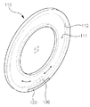
前記ベース板110は、イメージボード100の本体を形成する板状の部材として、前記回転車輪200に備えられたホイール210の外側部または内部に直立配置されてホイール210に対して独立して回転可能に装着される。
The
そして、ベース板110の一側面または両側面には、所定のイメージ(I)が配置され、回転軸線(L)を中心に円周方向に沿って延長形成された移動空間111が設けられたチャンバ112を含んで具備される。
A chamber in which a predetermined image (I) is arranged on one side surface or both side surfaces of the
ここで、前記ベース板110は、ベアリング150に締結されてホイール210の外側部や内部に直立配置された状態で、ベアリング150を介してホイール210に対して独立して回転可能に装着することができる。
Here, the
前記イメージ(I)は、ロゴ、エンブレム又は広告イメージなど様々な形態のデザインイメージとして、ベース板110の表面にイメージ(I)が図案どおりに印刷されたり、前記イメージ(I)が印刷されたシート紙がベース板110に付着されたり、別のイメージ板にイメージ(I)が印刷された状態で、イメージ版がベース板110に装着されたり、特定の形状を有する造形物が突出するように装着される形態で配置することができる。
The image (I) is a design image of various forms such as a logo, an emblem, or an advertisement image. The image (I) is printed on the surface of the
また、前記イメージ(I)は、自動車のホイール210のように駆動軸が連結される内側部は露出されず、外側が外部に露出される場合、ベース板110の外側面に配置され、自転車のホイール210のようにスポーク215を介して、両側が同時に外部に露出される場合には、ベース板110の両側面にそれぞれ配置され、イメージ表出効果を増大させることが望ましい。
In addition, the image (I) is arranged on the outer surface of the
そして、前記チャンバ112は、補償ウェイト130を位置移動させるための空間及び経路を提供する構成として、前記ベース板110の側部または中央部に配置され、ベース板110の回転軸線(L)を中心に回転する環状の移動空間111が設けられる。
The
図面には、前記ベース板110が円板状であることを例示したが、これに限定されるものではなく、楕円形、三角形、四角形、多角形などのように、全体的な形状において限定されない。ただし、前記チャンバ112は、「O」字状または「C」字状のように、全体的に円形状を有することが好ましい。
In the drawing, the
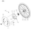
また、図3及び図4に示すように外側部のみが外部に露出されるホイール210の場合、前記イメージボード100は、ホイール210の外側部に回転可能に装着されるが、そのために締結板140、ベアリング150及び固定軸160をさらに含んで具備される。
Also, if a
より具体的に説明すると、前記締結板140は、ホイール210の側部に直立に締結され、イメージボード100がホイール210に回転可能に装着されるように支持する板材として、板状に形成され周囲にはホイール210に突出されるように配置された締結ねじ217に挿入されるための複数の締結孔141が形成され、中央には前記ベアリング150を締結させるための締結孔142が形成される。
To be more specific, the said
また、前記ベアリング150は、締結板140の中央部に締結されてホイール210の回転運動からイメージボード100を物理的に離隔させるための構成として、外側周囲は、締結板140の中央部に固定されるように締結され、内側には固定軸160が嵌合される。
Further, the
ここで、前記ベアリング150の場合、互いに異なる内径を有する複数の個別ベアリング151,152が相次いで内部に締結される構造で具備され、各個別ベアリング151,152の回転に伴う摩擦力及び慣性によってイメージボード100を回転させる回転力(F1、図11参照)を減少させることができる。
Here, in the case of the
前記固定軸160は、ベアリング150とベース板110との間に配置されるが、前記ベアリング150の中央部に嵌合されてベアリング150を介して、前記締結板140に対して回転可能に締結される軸部として、図3に示すように一端がベアリング150の内側に嵌合されて他端はベース板110の中央部に締結される。
The fixed
そして、前記固定軸160の他端には、ねじ結合のための締結孔161が形成され、図4に示すように、ベース板110上で、前記締結孔161と対応する位置に形成された締結孔113を連続貫通して回転結合される締結ねじ162によってベース板110の内側に強固に締結することができる。
A
一方、自転車、モーターサイクル、ゴルフカート、車椅子及び荷車などのようにスポーク215を介してホイール210の両側部が同時に露出される場合には、図7に示すように、イメージボード100がホイール210の外側部に装着されてもよいが、図8及び図9に示すようにホイール210の内部に回転可能に装着されてもよい。
On the other hand, the bicycle, when the motorcycle, golf cart, both sides of the
より具体的に説明すると、図7に示すようにホイール210の回転軸211にベアリング150の内側が嵌合され、ベース板110の中央にベアリング150の外側に嵌合されることにより前記ホイール210の外側部に直立配置された状態で独立して回転可能に締結されてもよい。
More specifically, as shown in FIG. 7, the inner side of the
ここで、上述した自動車のホイール210に締結される方式のようにベアリング150の内側を回転軸211に、より強固に装着させたり、ベアリング150の外側をベース板110により強固に装着させるための別の締結板(図示せず)が備えられてもよい。
Here, as in the method of being fastened to the
そして、図8及び図9に示すように、前記ベース板110は、ホイール210の内部に直立配置されて外部に突出していなくてもスポーク215によってイメージボード100を保護することができ、外観をより美しくすることができる。
8 and 9, the
このため、前記ベアリング150は、ホイール210に水平配置された回転軸211に内側の挿入孔が側方向に挿入されて嵌合され、前記ベース板110は、ベアリング150の外側に締結されて前記ホイール210の内部に直立配置された状態で、ベアリング150を介してホイール210に対して独立して回転可能に装着することができる。
For this reason, the
前記メインウェイト120は、ホイール210が回転しても、イメージボード100に配置されたイメージ(I)が常に固定された状態で表示されるように、ベース板110の下部に荷重を加えるウェイトとして、図3及び図4に示すように、外部に表示しようとするイメージ(I)が直立に配置された状態のベース板110上で偏心した下部位置に固定装着されてベース板110の下部に荷重を加える機能を果たす。
The
ここで、図面には、前記メインウェイト120が湾曲したバー形状であることを例示したが、これに限定されず、円板や球状などのように、ベース板110の下部に荷重を加えながら、外部の空気との摩擦を最小限に抑えることができれば、その形状には制限がない。
Here, the drawing illustrates that the
そして、図10〜図11に示すように、前記メインウェイト120は、移動手段1の走行により流入される走行風力により前記ホイール210と反対方向に回転するインペラ120であってもよい。
As shown in FIGS. 10 to 11, the
前記インペラ120の場合、ホイール210が高速回転しても、ベース板110に配置されたイメージ(I)が常に固定された状態で表示されうるようにホイール210の回転に応じて発生する回転力(F1)を相殺させるための反対方向の回転力(F2、図11参照)を生成する。
In the case of the
より具体的に説明すると、前記インペラ120の回転軸121端部は、ベース板110の下部に固定設置され、回転軸121の周囲には、前方から吹いてくる走行風力に摩擦されながらホイール210と反対方向に回転することができるように折り曲げたり、傾斜形態を有する多数の回転翼122が配置される。したがって、前記回転翼122は、回転軸121を中心に走行風力によって回転しながら、前記回転力(F2)を生成するようになる。
More specifically, the end of the
このように、ベース板110の下部に配置されて移動手段1の走行により流入される走行風力によってホイール210と反対方向に回転するインペラ120を装着することで、前記インペラ120の回転に伴う慣性力(F2)と回転翼122に加わる摩擦力(F2)によって移動手段1の走行によりホイール210が回転しながら発生する回転力(F1)が相殺されるので、前記ホイール210の回転とは無関係に常に固定された状態のイメージ(I)を表示することができる。ここで、前記回転翼122の回転に応じてホイール210の回転方向とは反対方向に生成される慣性力(F2)は、ジャイロ現象に起因する。
In this way, the inertial force accompanying the rotation of the
一方、前記ベース板110と比較して相対的に直径が大きい板状に形成され、ベース板110の一側面または縁に直立装着され、一側面または両側面に所定のイメージ(I)が配置された拡張板113をさらに含んで備えられてもよい。
On the other hand, it is formed in a plate shape having a relatively large diameter compared to the
より具体的に説明すると、図7に示すように、前記拡張板113は、直径が大きい円板状に形成され、ベース板110の一側面をカバーする形態で内側面の中央がベース板110に締結され、外側面には、前記イメージ(I)が配置されてもよい。
More specifically, as shown in FIG. 7, the
また、図12及び図13に示すように、前記拡張板113は、環状に形成され、内径周囲がベース板110の縁に装着され、外部面には、前記ベース板110に配置されたイメージ(I)と連携したり、独立した形状のイメージ(I)が配置されてもよい。ここで、図のように、ベース板110の縁端部には、装着された拡張板113の内径周囲の一側を支持するための段差116が形成され、前記拡張板113は、内径周囲の一側が前記段差116に支持された状態で、環状の締結環により内径周囲の他側が加圧され、ねじ結合されてベース板110上に強固に締結することができる。
As shown in FIGS. 12 and 13, the
ここで、図12に示すように、前記ベース板110に拡張板113が装着された場合、下部に荷重を加えるメインウェイト120は、拡張板113の偏心した下部位置に装着されてもよいが、これによりチャンバ112の下部位置に装着された場合と比較して、回転軸線(L)からよりも離間されることによって、ベース板110に前記回転力(F2)がより大きく作用するように備えられることが望ましい。
Here, as shown in FIG. 12, when the
また、前記拡張板113は、環状に形成され、内径周囲がベース板110の縁に装着された場合、図13に示すように、フレキシブルな材質からなり円周上の一箇所に幅方向に切開されたスリット溝115が配置されて前記スリット溝115を介してスポーク215の内部に挿入してベース板110に着脱する方式で交換することができるように備えられることが望ましい。
The
前記補償ウェイト130は、移動空間111の内部に配置され、前記メインウェイト120が前記ベース板110とともに、任意の方向に回転することにより、移動空間111内で位置移動して前記メインウェイト120が元の位置に復帰するように荷重を加える。
The
ここで、図3及び図4に示すように、前記補償ウェイト130は、移動空間111の内部に所定量注入されて前記メインウェイト120が回転することにより、荷重によって水面が平行になるように位置移動して、メインウェイト120が元の位置に復帰するようにベース板110に荷重を加える流体130であってもよい。
Here, as shown in FIG. 3 and FIG. 4, the
したがって、図14に示すように、ベース板110が回転しながら、メインウェイト120が時計方向に回転する場合、移動空間111内で流体130の右側部分は下降し、左側部分は昇降する位置移動によりベース板110の下部方向に流体130の荷重が加わりながらメインウェイト120は反時計方向に回転しながら元の位置に復帰するようになり、これによりベース板110のイメージ(I)は、元の状態を維持することができるようになる。
Therefore, as shown in FIG. 14, when the
逆に、前記メインウェイト120が反時計方向に回転する場合、移動空間111内で流体130の左側部分は下降し、右側部分は昇降する位置移動によりベース板110の下部方向に流体130の荷重が加わりながら、前記メインウェイト120は、時計方向に回転しながら元の位置に復帰するようになり、これによりベース板110のイメージ(I)は、元の状態を維持することができるようになる。
On the contrary, when the
また、前記流体130として、水のような一般的な流体と比較して相対的に氷結温度が低い不凍液(Antifreezing Liquid)を利用することにより、冬期などの極寒期やロシアのような極寒地域で流体130が氷結しない状態でイメージボード100を通常動作させることができる。
In addition, by using an antifreeze liquid (Antifreezing Liquid) having a relatively low freezing temperature as compared with a general fluid such as water, the fluid 130 can be used in an extremely cold period such as winter or an extremely cold area such as Russia. The
このように、前記補償ウェイト130としてチャンバ112の移動空間111内部に所定量注入される流体130を用いることにより、前記メインウェイト120が回転することによって瞬間的に移動空間111内で水面が平行になるように位置移動するので、前記メインウェイト120が元の位置に復帰するように荷重が加わる動作反応速度を極大化することができる。
As described above, by using the fluid 130 injected into the moving
一方、図16及び図17に示すように、前記補償ウェイト130は、円板または球状に形成され、移動空間111内部に配置されて、メインウェイト120が回転することにより、移動空間111の内部面に沿って転がりながら移動空間111の下部に位置移動して、メインウェイト120が元の位置に復帰するようにホイールカバー部140に荷重を提供するように具備されてもよい。
On the other hand, as shown in FIGS. 16 and 17, the
また、前記メインウェイト120を元の位置に復帰するのに必要な荷重の大きさに応じて、円板または球の大きさは調節されたり、複数が同時に移動空間111に配置することができる。
Also, the size of the disk or sphere can be adjusted according to the magnitude of the load required to return the
以上で説明した本発明は、前述した実施例及び添付された図面によって限定されるものではなく、本発明の技術的思想を逸脱しない範囲内で様々な置換、変形及び変更が可能であることは、本発明が属する技術分野において通常の知識を有する者に明らかであろう。 The present invention described above is not limited by the above-described embodiments and the accompanying drawings, and various substitutions, modifications and changes can be made without departing from the technical idea of the present invention. It will be apparent to those skilled in the art to which the present invention pertains.
Claims (11)
前記回転車輪のホイールの外側または内側に、前記ホイールに対して独立に回転可能に配置され、一面または両面に所定のイメージが配置され、回転軸を中心に円周方向に沿って空間が形成されたチャンバーを含むベース板と、
前記ベース板の下部に設けられ、前記ベース板の下部に荷重を加える第1ウェイトと、
前記空間の内部に配置される第2ウェイトと、
を備え、
前記第1ウェイトは、前記移動手段の走行に伴って流入する走行風力によって前記回転車輪の回転方向とは反対方向に回転するインペラを含む、
回転車輪用のイメージボード。 Moving the hand mounted on the rotational stage, an image board for rotating the wheel for displaying the images of the stop state regardless of the rotation of the rotating wheel,
Inside was outside side or the WHEEL of the rotating wheel, the rotatably disposed independently with respect to the wheel, one Menma others are arranged a predetermined images on both sides, a circle about an axis of rotation a base plate including a chamber over the space has been made form along the circumferential direction,
A first weight provided at a lower portion of the base plate and applying a load to the lower portion of the base plate ;
A second weight that will be placed inside the front Symbol space,
Equipped with a,
The first weight includes an impeller that rotates in a direction opposite to a rotation direction of the rotating wheel by a traveling wind force that flows in as the traveling unit travels.
Image board for the rotating wheel.
請求項1に記載の回転車輪用のイメージボード。 Is formed of a plate-shaped member having a larger diameter Ri by previous SL base plate is mounted to one side or the periphery of the base plate, further comprising an extension plate that will be located a predetermined images on one or both sides,
An image board for a rotating wheel according to claim 1.
前記回転車輪のホイールの外側または内側に、前記ホイールに対して独立に回転可能に配置され、一面または両面に所定のイメージが配置され、回転軸を中心に円周方向に沿って空間が形成されたチャンバーを含むベース板と、
前記ベース板より大きい直径を有する板形部材で形成され、ベース板の一側面または周縁部に装着され、一面または両面に所定のイメージが配置される拡張板と、
前記拡張板の下部に設けられ、前記ベース板の下部に荷重を加える第1ウェイトと、
前記空間の内部に配置される第2ウェイトと、
を備え、
前記第1ウェイトは、前記移動手段の走行に伴って流入する走行風力によって前記回転車輪の回転方向とは反対方向に回転するインペラを含む、
回転車輪用のイメージボード。 An image board for a rotating wheel that is mounted on a rotating wheel of a moving means and displays an image of a stopped state regardless of the rotation of the rotating wheel,
The rotating wheel is arranged outside or inside the wheel so as to be independently rotatable with respect to the wheel, a predetermined image is arranged on one or both surfaces, and a space is formed along the circumferential direction around the rotation axis. A base plate including a chamber,
An extension plate that is formed of a plate-shaped member having a diameter larger than that of the base plate, is attached to one side or a peripheral portion of the base plate, and a predetermined image is arranged on one or both sides;
A first weight that is provided at a lower portion of the extension plate and applies a load to a lower portion of the base plate;
A second weight disposed inside the space;
With
The first way bets, including the impeller La which rotates in the opposite direction to the rotation direction of the rotating wheel wheel me by the traveling wind you flows along with the traveling of the mobile hand stage,
Image board for the rotating wheel.
請求項2又は3に記載の回転車輪用のイメージボード。 The image board for rotating wheels of Claim 2 or 3.
請求項2又は3に記載の回転車輪用のイメージボード。 The image board for rotating wheels of Claim 2 or 3.
請求項5に記載の回転車輪用のイメージボード。 An image board for a rotating wheel according to claim 5.
請求項1ないし6の何れか一項に記載の回転車輪用のイメージボード。 It said second weight comprises a flow body,
The image board for rotating wheels as described in any one of Claims 1 thru | or 6 .
請求項7に記載の回転車輪用のイメージボード。 An image board for a rotating wheel according to claim 7.
請求項1ないし6の何れか一項に記載の回転車輪用のイメージボード。 The image board for rotating wheels as described in any one of Claims 1 thru | or 6.
回転車輪。 Rotating wheels.
移動手段。 transportation.
Applications Claiming Priority (5)
| Application Number | Priority Date | Filing Date | Title |
|---|---|---|---|
| KR10-2014-0044227 | 2014-04-14 | ||
| KR20140044227 | 2014-04-14 | ||
| KR10-2015-0035796 | 2015-03-16 | ||
| KR1020150035796A KR101768044B1 (en) | 2014-04-14 | 2015-03-16 | Image Board For Rotation Wheel And, Rotation Wheel Including The Same |
| PCT/KR2015/003094 WO2015160111A1 (en) | 2014-04-14 | 2015-03-30 | Image board for rotary wheel and rotary wheel comprising same |
Publications (3)
| Publication Number | Publication Date |
|---|---|
| JP2017514753A JP2017514753A (en) | 2017-06-08 |
| JP2017514753A5 JP2017514753A5 (en) | 2018-08-30 |
| JP6484701B2 true JP6484701B2 (en) | 2019-03-13 |
Family
ID=54426953
Family Applications (1)
| Application Number | Title | Priority Date | Filing Date |
|---|---|---|---|
| JP2017506236A Active JP6484701B2 (en) | 2014-04-14 | 2015-03-30 | Rotating wheel image board and rotating wheel including the same |
Country Status (6)
| Country | Link |
|---|---|
| US (1) | US10046596B2 (en) |
| EP (1) | EP3132946B1 (en) |
| JP (1) | JP6484701B2 (en) |
| KR (1) | KR101768044B1 (en) |
| CN (1) | CN106660389B (en) |
| ES (1) | ES2722426T3 (en) |
Families Citing this family (2)
| Publication number | Priority date | Publication date | Assignee | Title |
|---|---|---|---|---|
| JP7138882B2 (en) | 2018-03-14 | 2022-09-20 | 株式会社サンケミカル | Spoke wheel decoration device |
| DE102019202507B4 (en) * | 2019-02-25 | 2021-02-18 | Volkswagen Aktiengesellschaft | Rotatable decorative element |
Family Cites Families (17)
| Publication number | Priority date | Publication date | Assignee | Title |
|---|---|---|---|---|
| JPS5639683Y2 (en) * | 1978-06-27 | 1981-09-16 | ||
| US4280293A (en) * | 1979-12-26 | 1981-07-28 | Kovalenko Eugene N | Stationary display member for a rotating hub cap |
| JP3126124B1 (en) * | 1999-12-03 | 2001-01-22 | 株式会社シンセイ | Stationary plate device and rotating body device with stationary plate |
| US20020125761A1 (en) * | 1999-12-03 | 2002-09-12 | Kabushiki Kaisha Shinsei | Static plate device and static plate-equipped rotary body |
| JP2001354001A (en) * | 2000-06-12 | 2001-12-25 | Shoei Shoji Kk | Indicator mounted on car wheel |
| KR20020047469A (en) * | 2000-12-13 | 2002-06-22 | 류정열 | Inner structure of wheel for automobiles |
| JP2002370501A (en) * | 2001-04-11 | 2002-12-24 | Mitsumi Electric Co Ltd | Wheel cap |
| KR200252849Y1 (en) * | 2001-07-24 | 2001-11-23 | 류충섭 | Wheel cover |
| KR20040107907A (en) * | 2003-06-14 | 2004-12-23 | 배운호 | a tire wheel for bill board of battle neither have not |
| JP2005178493A (en) * | 2003-12-18 | 2005-07-07 | Ntn Corp | Wheel cap |
| KR100767600B1 (en) | 2007-03-29 | 2007-10-17 | 이일섭 | The non-rotation advertisement apparatus attached to the wheel of car |
| KR101167826B1 (en) | 2009-07-08 | 2012-07-26 | 류충섭 | wheel-cover structure for automobile |
| KR101147057B1 (en) * | 2010-12-23 | 2012-05-17 | 김상국 | Advertisement device for wheel cap |
| US8517474B2 (en) * | 2011-06-20 | 2013-08-27 | Mazen Yousef Falah Salah | Non-rotating wheel cap |
| KR101380303B1 (en) * | 2011-11-01 | 2014-04-01 | 이주원 | Wheel cover of vehicles |
| KR101540103B1 (en) * | 2013-12-04 | 2015-07-30 | 유충섭 | Wheel Cover Apparatus For Automobile |
| US20150170558A1 (en) * | 2013-12-12 | 2015-06-18 | Mazen Yousef Falah Salah | Non-Rotating Wheel Cap |
-
2015
- 2015-03-16 KR KR1020150035796A patent/KR101768044B1/en active IP Right Grant
- 2015-03-30 CN CN201580020018.0A patent/CN106660389B/en not_active Expired - Fee Related
- 2015-03-30 JP JP2017506236A patent/JP6484701B2/en active Active
- 2015-03-30 US US15/304,405 patent/US10046596B2/en active Active
- 2015-03-30 ES ES15780739T patent/ES2722426T3/en active Active
- 2015-03-30 EP EP15780739.7A patent/EP3132946B1/en not_active Not-in-force
Also Published As
| Publication number | Publication date |
|---|---|
| US20170043615A1 (en) | 2017-02-16 |
| EP3132946A4 (en) | 2017-12-20 |
| US10046596B2 (en) | 2018-08-14 |
| EP3132946B1 (en) | 2019-01-30 |
| CN106660389A (en) | 2017-05-10 |
| JP2017514753A (en) | 2017-06-08 |
| EP3132946A1 (en) | 2017-02-22 |
| CN106660389B (en) | 2019-01-11 |
| KR101768044B1 (en) | 2017-08-30 |
| KR20150118529A (en) | 2015-10-22 |
| ES2722426T3 (en) | 2019-08-12 |
Similar Documents
| Publication | Publication Date | Title |
|---|---|---|
| EP2537683B1 (en) | Non-rotating wheel cap | |
| JP3737971B2 (en) | Non-rotating indicator attached to a rotating body | |
| US20160243892A1 (en) | Non-Rotating Wheel Cap | |
| JP6484701B2 (en) | Rotating wheel image board and rotating wheel including the same | |
| JP6839847B2 (en) | Omni-directional moving wheels and omnidirectional moving vehicles equipped with them | |
| JP2017514753A5 (en) | ||
| US20070164600A1 (en) | Wheel rim structure | |
| KR101380303B1 (en) | Wheel cover of vehicles | |
| JP2005538892A (en) | Vehicle performance improvement device | |
| JP2005538892A5 (en) | ||
| CN102510809A (en) | Wheel cover for a vehicle | |
| JP6431927B2 (en) | Rotating wheel image board and rotating wheel including the same | |
| JP2017502878A5 (en) | ||
| KR101276411B1 (en) | advertising wheel cap assembly for automobile | |
| JP5488337B2 (en) | Vehicle power unit | |
| TW201702119A (en) | Straddled electric vehicle | |
| WO2015160111A1 (en) | Image board for rotary wheel and rotary wheel comprising same | |
| KR200307559Y1 (en) | nonrotating billboard of rotation body | |
| KR100594631B1 (en) | non-rotational emblem displayer for wheel cap | |
| US20120144954A1 (en) | Advanced steering wheel | |
| JP2007182144A (en) | Wheel | |
| JP2022181295A (en) | Bicycle wheel, bicycle, and hub | |
| KR200286416Y1 (en) | Wheel cap for automobile | |
| JP2005001617A (en) | Wheel indicator | |
| JP2019156226A (en) | Decorative device of spoke wheel |
Legal Events
| Date | Code | Title | Description |
|---|---|---|---|
| A621 | Written request for application examination |
Free format text: JAPANESE INTERMEDIATE CODE: A621 Effective date: 20180326 |
|
| A711 | Notification of change in applicant |
Free format text: JAPANESE INTERMEDIATE CODE: A711 Effective date: 20180604 |
|
| RD02 | Notification of acceptance of power of attorney |
Free format text: JAPANESE INTERMEDIATE CODE: A7422 Effective date: 20180604 |
|
| A521 | Request for written amendment filed |
Free format text: JAPANESE INTERMEDIATE CODE: A523 Effective date: 20180605 |
|
| A521 | Request for written amendment filed |
Free format text: JAPANESE INTERMEDIATE CODE: A821 Effective date: 20180604 |
|
| A521 | Request for written amendment filed |
Free format text: JAPANESE INTERMEDIATE CODE: A523 Effective date: 20180626 |
|
| A977 | Report on retrieval |
Free format text: JAPANESE INTERMEDIATE CODE: A971007 Effective date: 20190124 |
|
| TRDD | Decision of grant or rejection written | ||
| A01 | Written decision to grant a patent or to grant a registration (utility model) |
Free format text: JAPANESE INTERMEDIATE CODE: A01 Effective date: 20190129 |
|
| A61 | First payment of annual fees (during grant procedure) |
Free format text: JAPANESE INTERMEDIATE CODE: A61 Effective date: 20190218 |
|
| R150 | Certificate of patent or registration of utility model |
Ref document number: 6484701 Country of ref document: JP Free format text: JAPANESE INTERMEDIATE CODE: R150 |
|
| R250 | Receipt of annual fees |
Free format text: JAPANESE INTERMEDIATE CODE: R250 |
|
| R250 | Receipt of annual fees |
Free format text: JAPANESE INTERMEDIATE CODE: R250 |
|
| R250 | Receipt of annual fees |
Free format text: JAPANESE INTERMEDIATE CODE: R250 |