JP6483668B2 - Vapor sensor suitable for detecting residual alcohol in skin areas - Google Patents
Vapor sensor suitable for detecting residual alcohol in skin areas Download PDFInfo
- Publication number
- JP6483668B2 JP6483668B2 JP2016517364A JP2016517364A JP6483668B2 JP 6483668 B2 JP6483668 B2 JP 6483668B2 JP 2016517364 A JP2016517364 A JP 2016517364A JP 2016517364 A JP2016517364 A JP 2016517364A JP 6483668 B2 JP6483668 B2 JP 6483668B2
- Authority
- JP
- Japan
- Prior art keywords
- housing
- inlet opening
- vapor
- sensor element
- skin site
- Prior art date
- Legal status (The legal status is an assumption and is not a legal conclusion. Google has not performed a legal analysis and makes no representation as to the accuracy of the status listed.)
- Active
Links
- LFQSCWFLJHTTHZ-UHFFFAOYSA-N Ethanol Chemical compound CCO LFQSCWFLJHTTHZ-UHFFFAOYSA-N 0.000 title claims description 56
- 238000002955 isolation Methods 0.000 claims description 43
- 238000004891 communication Methods 0.000 claims description 27
- 238000000034 method Methods 0.000 claims description 24
- 239000012298 atmosphere Substances 0.000 claims description 16
- 239000003989 dielectric material Substances 0.000 claims description 15
- 239000012530 fluid Substances 0.000 claims description 11
- 230000002596 correlated effect Effects 0.000 claims description 6
- 238000001514 detection method Methods 0.000 claims description 3
- 235000019441 ethanol Nutrition 0.000 description 45
- 239000000463 material Substances 0.000 description 31
- 229920000642 polymer Polymers 0.000 description 14
- 239000000203 mixture Substances 0.000 description 10
- 238000000576 coating method Methods 0.000 description 9
- 239000011248 coating agent Substances 0.000 description 8
- OKTJSMMVPCPJKN-UHFFFAOYSA-N Carbon Chemical compound [C] OKTJSMMVPCPJKN-UHFFFAOYSA-N 0.000 description 7
- 229910052751 metal Inorganic materials 0.000 description 7
- 239000002184 metal Substances 0.000 description 7
- 230000002745 absorbent Effects 0.000 description 6
- 239000002250 absorbent Substances 0.000 description 6
- 238000001035 drying Methods 0.000 description 6
- 239000011148 porous material Substances 0.000 description 6
- KFZMGEQAYNKOFK-UHFFFAOYSA-N Isopropanol Chemical compound CC(C)O KFZMGEQAYNKOFK-UHFFFAOYSA-N 0.000 description 5
- 239000000853 adhesive Substances 0.000 description 5
- 230000001070 adhesive effect Effects 0.000 description 5
- 239000012491 analyte Substances 0.000 description 5
- 239000011159 matrix material Substances 0.000 description 5
- 239000002904 solvent Substances 0.000 description 5
- PXHVJJICTQNCMI-UHFFFAOYSA-N Nickel Chemical compound [Ni] PXHVJJICTQNCMI-UHFFFAOYSA-N 0.000 description 4
- KDLHZDBZIXYQEI-UHFFFAOYSA-N Palladium Chemical compound [Pd] KDLHZDBZIXYQEI-UHFFFAOYSA-N 0.000 description 4
- BQCADISMDOOEFD-UHFFFAOYSA-N Silver Chemical compound [Ag] BQCADISMDOOEFD-UHFFFAOYSA-N 0.000 description 4
- 239000004020 conductor Substances 0.000 description 4
- 238000009472 formulation Methods 0.000 description 4
- PCHJSUWPFVWCPO-UHFFFAOYSA-N gold Chemical compound [Au] PCHJSUWPFVWCPO-UHFFFAOYSA-N 0.000 description 4
- 229910052737 gold Inorganic materials 0.000 description 4
- 239000010931 gold Substances 0.000 description 4
- 239000002245 particle Substances 0.000 description 4
- BASFCYQUMIYNBI-UHFFFAOYSA-N platinum Chemical compound [Pt] BASFCYQUMIYNBI-UHFFFAOYSA-N 0.000 description 4
- 238000007639 printing Methods 0.000 description 4
- 229910052709 silver Inorganic materials 0.000 description 4
- 239000004332 silver Substances 0.000 description 4
- 229910021393 carbon nanotube Inorganic materials 0.000 description 3
- 239000002041 carbon nanotube Substances 0.000 description 3
- 239000002131 composite material Substances 0.000 description 3
- 239000000428 dust Substances 0.000 description 3
- 238000004519 manufacturing process Methods 0.000 description 3
- 239000003960 organic solvent Substances 0.000 description 3
- -1 polyethylene Polymers 0.000 description 3
- 230000008569 process Effects 0.000 description 3
- 239000000758 substrate Substances 0.000 description 3
- 238000007740 vapor deposition Methods 0.000 description 3
- VYZAMTAEIAYCRO-UHFFFAOYSA-N Chromium Chemical compound [Cr] VYZAMTAEIAYCRO-UHFFFAOYSA-N 0.000 description 2
- RYGMFSIKBFXOCR-UHFFFAOYSA-N Copper Chemical compound [Cu] RYGMFSIKBFXOCR-UHFFFAOYSA-N 0.000 description 2
- WYURNTSHIVDZCO-UHFFFAOYSA-N Tetrahydrofuran Chemical compound C1CCOC1 WYURNTSHIVDZCO-UHFFFAOYSA-N 0.000 description 2
- ATJFFYVFTNAWJD-UHFFFAOYSA-N Tin Chemical compound [Sn] ATJFFYVFTNAWJD-UHFFFAOYSA-N 0.000 description 2
- RTAQQCXQSZGOHL-UHFFFAOYSA-N Titanium Chemical compound [Ti] RTAQQCXQSZGOHL-UHFFFAOYSA-N 0.000 description 2
- 239000000654 additive Substances 0.000 description 2
- 239000000956 alloy Substances 0.000 description 2
- 229910045601 alloy Inorganic materials 0.000 description 2
- 229910052782 aluminium Inorganic materials 0.000 description 2
- XAGFODPZIPBFFR-UHFFFAOYSA-N aluminium Chemical compound [Al] XAGFODPZIPBFFR-UHFFFAOYSA-N 0.000 description 2
- 230000000845 anti-microbial effect Effects 0.000 description 2
- 230000008859 change Effects 0.000 description 2
- MVPPADPHJFYWMZ-UHFFFAOYSA-N chlorobenzene Chemical compound ClC1=CC=CC=C1 MVPPADPHJFYWMZ-UHFFFAOYSA-N 0.000 description 2
- 229910052804 chromium Inorganic materials 0.000 description 2
- 239000011651 chromium Substances 0.000 description 2
- 229910052802 copper Inorganic materials 0.000 description 2
- 239000010949 copper Substances 0.000 description 2
- 239000000499 gel Substances 0.000 description 2
- 238000010438 heat treatment Methods 0.000 description 2
- AMGQUBHHOARCQH-UHFFFAOYSA-N indium;oxotin Chemical compound [In].[Sn]=O AMGQUBHHOARCQH-UHFFFAOYSA-N 0.000 description 2
- 229910010272 inorganic material Inorganic materials 0.000 description 2
- 239000011147 inorganic material Substances 0.000 description 2
- 238000003780 insertion Methods 0.000 description 2
- 230000037431 insertion Effects 0.000 description 2
- 239000004816 latex Substances 0.000 description 2
- 229920000126 latex Polymers 0.000 description 2
- 239000007788 liquid Substances 0.000 description 2
- 238000005259 measurement Methods 0.000 description 2
- 229910044991 metal oxide Inorganic materials 0.000 description 2
- 150000004706 metal oxides Chemical class 0.000 description 2
- 150000002739 metals Chemical class 0.000 description 2
- 229910052759 nickel Inorganic materials 0.000 description 2
- 230000005693 optoelectronics Effects 0.000 description 2
- 239000011368 organic material Substances 0.000 description 2
- 229910052763 palladium Inorganic materials 0.000 description 2
- 238000000206 photolithography Methods 0.000 description 2
- 230000000704 physical effect Effects 0.000 description 2
- 229910052697 platinum Inorganic materials 0.000 description 2
- 230000004044 response Effects 0.000 description 2
- 239000007787 solid Substances 0.000 description 2
- 238000001179 sorption measurement Methods 0.000 description 2
- 238000004659 sterilization and disinfection Methods 0.000 description 2
- 239000000126 substance Substances 0.000 description 2
- 238000002198 surface plasmon resonance spectroscopy Methods 0.000 description 2
- 229910052718 tin Inorganic materials 0.000 description 2
- 239000011135 tin Substances 0.000 description 2
- 229910052719 titanium Inorganic materials 0.000 description 2
- 239000010936 titanium Substances 0.000 description 2
- XLYOFNOQVPJJNP-UHFFFAOYSA-N water Substances O XLYOFNOQVPJJNP-UHFFFAOYSA-N 0.000 description 2
- 239000010457 zeolite Substances 0.000 description 2
- POFMQEVZKZVAPQ-UHFFFAOYSA-N 1,1,1',1'-tetramethyl-3,3'-spirobi[2h-indene]-5,5',6,6'-tetrol Chemical compound C12=CC(O)=C(O)C=C2C(C)(C)CC11C2=CC(O)=C(O)C=C2C(C)(C)C1 POFMQEVZKZVAPQ-UHFFFAOYSA-N 0.000 description 1
- PCRSJGWFEMHHEW-UHFFFAOYSA-N 2,3,5,6-tetrafluorobenzene-1,4-dicarbonitrile Chemical compound FC1=C(F)C(C#N)=C(F)C(F)=C1C#N PCRSJGWFEMHHEW-UHFFFAOYSA-N 0.000 description 1
- 239000004698 Polyethylene Substances 0.000 description 1
- 239000004743 Polypropylene Substances 0.000 description 1
- 239000004820 Pressure-sensitive adhesive Substances 0.000 description 1
- VYPSYNLAJGMNEJ-UHFFFAOYSA-N Silicium dioxide Chemical compound O=[Si]=O VYPSYNLAJGMNEJ-UHFFFAOYSA-N 0.000 description 1
- 206010040880 Skin irritation Diseases 0.000 description 1
- DHXVGJBLRPWPCS-UHFFFAOYSA-N Tetrahydropyran Chemical compound C1CCOCC1 DHXVGJBLRPWPCS-UHFFFAOYSA-N 0.000 description 1
- 229910021536 Zeolite Inorganic materials 0.000 description 1
- 238000005299 abrasion Methods 0.000 description 1
- 238000010521 absorption reaction Methods 0.000 description 1
- 230000000996 additive effect Effects 0.000 description 1
- 239000002390 adhesive tape Substances 0.000 description 1
- 230000001476 alcoholic effect Effects 0.000 description 1
- 150000004945 aromatic hydrocarbons Chemical class 0.000 description 1
- WXNOJTUTEXAZLD-UHFFFAOYSA-L benzonitrile;dichloropalladium Chemical compound Cl[Pd]Cl.N#CC1=CC=CC=C1.N#CC1=CC=CC=C1 WXNOJTUTEXAZLD-UHFFFAOYSA-L 0.000 description 1
- 230000005540 biological transmission Effects 0.000 description 1
- 230000015572 biosynthetic process Effects 0.000 description 1
- 238000005266 casting Methods 0.000 description 1
- 239000003795 chemical substances by application Substances 0.000 description 1
- 238000009833 condensation Methods 0.000 description 1
- 230000005494 condensation Effects 0.000 description 1
- 239000011370 conductive nanoparticle Substances 0.000 description 1
- ZWAJLVLEBYIOTI-UHFFFAOYSA-N cyclohexene oxide Chemical compound C1CCCC2OC21 ZWAJLVLEBYIOTI-UHFFFAOYSA-N 0.000 description 1
- FWFSEYBSWVRWGL-UHFFFAOYSA-N cyclohexene oxide Natural products O=C1CCCC=C1 FWFSEYBSWVRWGL-UHFFFAOYSA-N 0.000 description 1
- 238000013461 design Methods 0.000 description 1
- 238000010586 diagram Methods 0.000 description 1
- HNPSIPDUKPIQMN-UHFFFAOYSA-N dioxosilane;oxo(oxoalumanyloxy)alumane Chemical compound O=[Si]=O.O=[Al]O[Al]=O HNPSIPDUKPIQMN-UHFFFAOYSA-N 0.000 description 1
- 238000003618 dip coating Methods 0.000 description 1
- 239000006185 dispersion Substances 0.000 description 1
- 238000011049 filling Methods 0.000 description 1
- 239000012456 homogeneous solution Substances 0.000 description 1
- 230000002209 hydrophobic effect Effects 0.000 description 1
- 239000013315 hypercross-linked polymer Substances 0.000 description 1
- 238000007641 inkjet printing Methods 0.000 description 1
- 239000002198 insoluble material Substances 0.000 description 1
- 238000009434 installation Methods 0.000 description 1
- 230000007794 irritation Effects 0.000 description 1
- WABPQHHGFIMREM-UHFFFAOYSA-N lead(0) Chemical compound [Pb] WABPQHHGFIMREM-UHFFFAOYSA-N 0.000 description 1
- 229920002521 macromolecule Polymers 0.000 description 1
- 238000012423 maintenance Methods 0.000 description 1
- 239000012229 microporous material Substances 0.000 description 1
- 238000012986 modification Methods 0.000 description 1
- 230000004048 modification Effects 0.000 description 1
- 230000000474 nursing effect Effects 0.000 description 1
- 230000003287 optical effect Effects 0.000 description 1
- 230000035699 permeability Effects 0.000 description 1
- 239000002985 plastic film Substances 0.000 description 1
- 229920006255 plastic film Polymers 0.000 description 1
- 229920000573 polyethylene Polymers 0.000 description 1
- 238000006116 polymerization reaction Methods 0.000 description 1
- 229920001155 polypropylene Polymers 0.000 description 1
- 239000000843 powder Substances 0.000 description 1
- 238000002360 preparation method Methods 0.000 description 1
- 230000001681 protective effect Effects 0.000 description 1
- 238000007650 screen-printing Methods 0.000 description 1
- 239000000741 silica gel Substances 0.000 description 1
- 229910002027 silica gel Inorganic materials 0.000 description 1
- 230000036556 skin irritation Effects 0.000 description 1
- 231100000475 skin irritation Toxicity 0.000 description 1
- 238000004528 spin coating Methods 0.000 description 1
- 238000005507 spraying Methods 0.000 description 1
- 238000004544 sputter deposition Methods 0.000 description 1
- 230000001954 sterilising effect Effects 0.000 description 1
- 238000010897 surface acoustic wave method Methods 0.000 description 1
- 238000001356 surgical procedure Methods 0.000 description 1
- 239000000725 suspension Substances 0.000 description 1
- YLQBMQCUIZJEEH-UHFFFAOYSA-N tetrahydrofuran Natural products C=1C=COC=1 YLQBMQCUIZJEEH-UHFFFAOYSA-N 0.000 description 1
Images


Classifications
-
- G—PHYSICS
- G01—MEASURING; TESTING
- G01N—INVESTIGATING OR ANALYSING MATERIALS BY DETERMINING THEIR CHEMICAL OR PHYSICAL PROPERTIES
- G01N33/00—Investigating or analysing materials by specific methods not covered by groups G01N1/00 - G01N31/00
- G01N33/0004—Gaseous mixtures, e.g. polluted air
- G01N33/0009—General constructional details of gas analysers, e.g. portable test equipment
- G01N33/0027—General constructional details of gas analysers, e.g. portable test equipment concerning the detector
- G01N33/0036—Specially adapted to detect a particular component
- G01N33/0047—Specially adapted to detect a particular component for organic compounds
-
- A—HUMAN NECESSITIES
- A61—MEDICAL OR VETERINARY SCIENCE; HYGIENE
- A61B—DIAGNOSIS; SURGERY; IDENTIFICATION
- A61B5/00—Measuring for diagnostic purposes; Identification of persons
- A61B5/145—Measuring characteristics of blood in vivo, e.g. gas concentration, pH value; Measuring characteristics of body fluids or tissues, e.g. interstitial fluid, cerebral tissue
- A61B5/14546—Measuring characteristics of blood in vivo, e.g. gas concentration, pH value; Measuring characteristics of body fluids or tissues, e.g. interstitial fluid, cerebral tissue for measuring analytes not otherwise provided for, e.g. ions, cytochromes
-
- A—HUMAN NECESSITIES
- A61—MEDICAL OR VETERINARY SCIENCE; HYGIENE
- A61B—DIAGNOSIS; SURGERY; IDENTIFICATION
- A61B5/00—Measuring for diagnostic purposes; Identification of persons
- A61B5/145—Measuring characteristics of blood in vivo, e.g. gas concentration, pH value; Measuring characteristics of body fluids or tissues, e.g. interstitial fluid, cerebral tissue
- A61B5/1468—Measuring characteristics of blood in vivo, e.g. gas concentration, pH value; Measuring characteristics of body fluids or tissues, e.g. interstitial fluid, cerebral tissue using chemical or electrochemical methods, e.g. by polarographic means
- A61B5/1477—Measuring characteristics of blood in vivo, e.g. gas concentration, pH value; Measuring characteristics of body fluids or tissues, e.g. interstitial fluid, cerebral tissue using chemical or electrochemical methods, e.g. by polarographic means non-invasive
-
- A—HUMAN NECESSITIES
- A61—MEDICAL OR VETERINARY SCIENCE; HYGIENE
- A61B—DIAGNOSIS; SURGERY; IDENTIFICATION
- A61B5/00—Measuring for diagnostic purposes; Identification of persons
- A61B5/48—Other medical applications
- A61B5/4845—Toxicology, e.g. by detection of alcohol, drug or toxic products
-
- G—PHYSICS
- G01—MEASURING; TESTING
- G01D—MEASURING NOT SPECIALLY ADAPTED FOR A SPECIFIC VARIABLE; ARRANGEMENTS FOR MEASURING TWO OR MORE VARIABLES NOT COVERED IN A SINGLE OTHER SUBCLASS; TARIFF METERING APPARATUS; MEASURING OR TESTING NOT OTHERWISE PROVIDED FOR
- G01D11/00—Component parts of measuring arrangements not specially adapted for a specific variable
- G01D11/24—Housings ; Casings for instruments
- G01D11/245—Housings for sensors
-
- G—PHYSICS
- G01—MEASURING; TESTING
- G01N—INVESTIGATING OR ANALYSING MATERIALS BY DETERMINING THEIR CHEMICAL OR PHYSICAL PROPERTIES
- G01N33/00—Investigating or analysing materials by specific methods not covered by groups G01N1/00 - G01N31/00
- G01N33/48—Biological material, e.g. blood, urine; Haemocytometers
- G01N33/483—Physical analysis of biological material
- G01N33/487—Physical analysis of biological material of liquid biological material
- G01N33/48707—Physical analysis of biological material of liquid biological material by electrical means
- G01N33/48714—Physical analysis of biological material of liquid biological material by electrical means for determining substances foreign to the organism, e.g. drugs or heavy metals
-
- A—HUMAN NECESSITIES
- A61—MEDICAL OR VETERINARY SCIENCE; HYGIENE
- A61B—DIAGNOSIS; SURGERY; IDENTIFICATION
- A61B10/00—Other methods or instruments for diagnosis, e.g. instruments for taking a cell sample, for biopsy, for vaccination diagnosis; Sex determination; Ovulation-period determination; Throat striking implements
- A61B10/0045—Devices for taking samples of body liquids
- A61B10/0064—Devices for taking samples of body liquids for taking sweat or sebum samples
-
- A—HUMAN NECESSITIES
- A61—MEDICAL OR VETERINARY SCIENCE; HYGIENE
- A61B—DIAGNOSIS; SURGERY; IDENTIFICATION
- A61B10/00—Other methods or instruments for diagnosis, e.g. instruments for taking a cell sample, for biopsy, for vaccination diagnosis; Sex determination; Ovulation-period determination; Throat striking implements
- A61B2010/0083—Other methods or instruments for diagnosis, e.g. instruments for taking a cell sample, for biopsy, for vaccination diagnosis; Sex determination; Ovulation-period determination; Throat striking implements for taking gas samples
-
- A—HUMAN NECESSITIES
- A61—MEDICAL OR VETERINARY SCIENCE; HYGIENE
- A61B—DIAGNOSIS; SURGERY; IDENTIFICATION
- A61B5/00—Measuring for diagnostic purposes; Identification of persons
- A61B5/44—Detecting, measuring or recording for evaluating the integumentary system, e.g. skin, hair or nails
-
- G—PHYSICS
- G01—MEASURING; TESTING
- G01N—INVESTIGATING OR ANALYSING MATERIALS BY DETERMINING THEIR CHEMICAL OR PHYSICAL PROPERTIES
- G01N33/00—Investigating or analysing materials by specific methods not covered by groups G01N1/00 - G01N31/00
- G01N33/48—Biological material, e.g. blood, urine; Haemocytometers
- G01N33/483—Physical analysis of biological material
- G01N33/497—Physical analysis of biological material of gaseous biological material, e.g. breath
- G01N33/4972—Determining alcohol content
Description
本開示は、環境中の化学蒸気を検出するためのセンサー及びその使用方法に関する。 The present disclosure relates to sensors for detecting chemical vapor in the environment and methods of use thereof.
カテーテルの設置に先立って皮膚消毒用のエチルアルコール又はイソプロピルアルコールなどの抗微生物製剤が一般的に使用されている。かかるアルコールベースの製剤からの残留蒸気は、その部位を更に準備してかつ/又はカテーテルを固定するためにその後に適用される粘着テープ及びドレッシングの効果を弱める恐れがある。更に、ドレープ及びドレッシングの適用前の皮膚の乾燥が不適切であっても患者の皮膚の刺激のリスクが高まる。 Prior to installation of the catheter, antimicrobial preparations such as ethyl alcohol or isopropyl alcohol for skin disinfection are generally used. Residual vapors from such alcohol-based formulations can weaken the effectiveness of adhesive tape and dressing that is subsequently applied to further prepare the site and / or secure the catheter. In addition, improper drying of the skin prior to application of drapes and dressings increases the risk of patient irritation.
1つの典型的なプロトコルとして、アルコールベースの抗微生物製剤を適用した後、処置した皮膚に更なる材料又は装置を適用する前に3分間の待ち時間を義務づけることがある。この時間は、看護スタッフに負担がかかることから常に守られているわけでなない。たとえこの時間が置かれたとしても、すべての条件でリスクが取り除かれることを保証するわけではない。例えば、アルコールベースの製剤が目につきにくい場所に不注意に溜まっており、蒸発するのに更に長時間を要する可能性もある。 One typical protocol may require a 3-minute wait after applying an alcohol-based antimicrobial formulation and before applying additional materials or devices to the treated skin. This time is not always protected from the burden on nursing staff. Even if this time is set, it does not guarantee that the risk is removed under all conditions. For example, alcohol-based formulations can be inadvertently stored in places where they are difficult to see and can take a longer time to evaporate.
一態様では、本開示は、皮膚部位の残留アルコールを検出するための蒸気センサーであって、
ハウジングであって、ハウジングの内部に延びる入口開口部を含むハウジングと、
ハウジング内に配置され、入口開口部と流体連通したセンサー素子であって、第1の導電性部材、第2の導電性部材、及び第1の導電性部材と第2の導電性部材との間に挟まれた吸収性誘電体材料を含むセンサー素子と、
ハウジングに隣接して配置される少なくとも1つの隔離部材であって、入口開口部と皮膚部位との間に隙間を維持するように配置された、少なくとも1つの隔離部材と、
センサー素子と電気的に導通し、センサー素子のパラメータを検出することが可能な作動回路であって、パラメータがアルコール濃度と相関したものである、作動回路と、
作動回路と通信可能に接続された少なくとも1つの出力部材であって、作動回路からの通信を受信すると、皮膚部位に隣接した周囲雰囲気中のアルコール蒸気の濃度に関して操作者に示される検知出力を生成するようになっている、少なくとも1つの出力部材と、を含む、蒸気センサーを提供する。
In one aspect, the present disclosure is a vapor sensor for detecting residual alcohol in a skin site,
A housing comprising an inlet opening extending into the housing;
A sensor element disposed within a housing and in fluid communication with an inlet opening, the first conductive member, a second conductive member, and between the first conductive member and the second conductive member A sensor element comprising an absorptive dielectric material sandwiched between,
At least one isolation member disposed adjacent to the housing, the at least one isolation member positioned to maintain a gap between the inlet opening and the skin site;
An actuation circuit that is in electrical communication with the sensor element and is capable of detecting a parameter of the sensor element, wherein the parameter is correlated with the alcohol concentration;
At least one output member communicatively connected to the actuation circuit, and upon receipt of the communication from the actuation circuit, generates a sensing output that is indicated to the operator with respect to the concentration of alcohol vapor in the ambient atmosphere adjacent to the skin site A vapor sensor comprising: at least one output member adapted to:
別の態様において、本開示は、残留アルコールを検出する方法であって、
皮膚部位の残留アルコールを検出するための蒸気センサーを用意する工程であって、蒸気センサーが、
ハウジングであって、ハウジングの内部に延びる入口開口部を含むハウジングと、
ハウジング内に配置され、入口開口部と流体連通したセンサー素子と、
ハウジングに隣接して配置される少なくとも1つの隔離部材であって、入口開口部と皮膚部位との間に隙間を維持するように配置された、少なくとも1つの隔離部材と、
センサー素子と電気的に導通し、センサー素子のパラメータを検出することが可能な作動回路であって、パラメータがアルコール濃度と相関したものである、作動回路と、
作動回路と通信可能に接続された少なくとも1つの出力部材であって、作動回路からの通信を受信すると、前記皮膚部位に隣接した周囲雰囲気中のアルコール蒸気の濃度に関して操作者に示される検知出力を生成するようになっている、少なくとも1つの出力部材と、を含むものである、工程と、
入口開口部が少なくとも1つの隔離部材によって皮膚部位から分離されるように皮膚部位に隣接して蒸気センサーを配置する工程と、
センサー素子が周囲雰囲気に曝露されるように皮膚部位に隣接した周囲雰囲気を入口開口部内に導入する工程と、
センサー素子のパラメータの値を測定する工程と、
パラメータの値に少なくとも部分的に基づいて、少なくとも1つの出力部材に検知出力を生成させる工程と、を含む、方法を提供する。
In another aspect, the present disclosure is a method for detecting residual alcohol comprising:
A step of preparing a vapor sensor for detecting residual alcohol in the skin site, wherein the vapor sensor is
A housing comprising an inlet opening extending into the housing;
A sensor element disposed in the housing and in fluid communication with the inlet opening;
At least one isolation member disposed adjacent to the housing, the at least one isolation member positioned to maintain a gap between the inlet opening and the skin site;
An actuation circuit that is in electrical communication with the sensor element and is capable of detecting a parameter of the sensor element, wherein the parameter is correlated with the alcohol concentration;
At least one output member communicatively coupled to the actuation circuit, and upon receiving communication from the actuation circuit, provides a sensing output indicated to the operator regarding the concentration of alcohol vapor in the ambient atmosphere adjacent to the skin site. At least one output member adapted to generate a process,
Positioning the vapor sensor adjacent to the skin site such that the inlet opening is separated from the skin site by at least one isolation member;
Introducing an ambient atmosphere adjacent to the skin site into the inlet opening so that the sensor element is exposed to the ambient atmosphere;
Measuring the parameter value of the sensor element;
Causing at least one output member to generate a sensing output based at least in part on the value of the parameter.
有利な点として、本開示による蒸気センサーは、比較的安価でメンテナンスフリーであり、アルコール蒸気が、皮膚の刺激及び/又は接着の問題を防止するうえで許容される閾値濃度よりも低いことを分かりやすく示すことができる携帯型の構成(例えば、手持ち式モデル)で製造することができる。 Advantageously, the vapor sensor according to the present disclosure is relatively inexpensive and maintenance free, and it is found that alcohol vapor is below a threshold concentration that is acceptable to prevent skin irritation and / or adhesion problems. It can be manufactured in a portable configuration that can be easily shown (eg, a hand-held model).
本明細書で使用するところの「吸収性」なる用語は、材料(例えば、微多孔性ポリマー)中の内部空間の側面で生じる吸収及び吸着を含む。 As used herein, the term “absorbent” includes absorption and adsorption that occurs at the sides of the interior space in a material (eg, a microporous polymer).
特に断わらないかぎり、「アルコール」(並びに「アルコール性」及び「アルコールベースの」)なる用語は、エタノール及び/又はイソプロパノールを指す。 Unless otherwise indicated, the term “alcohol” (and “alcoholic” and “alcohol-based”) refers to ethanol and / or isopropanol.
本明細書で使用するところの「皮膚部位」なる用語は、手術を行う前又は手技を行う前(例えばカテーテルを挿入する前)の部位の、又はその部位に隣接した動物の皮膚(例えば、ヒトの皮膚)を指す。 As used herein, the term “skin site” refers to the skin of an animal (eg, a human being) at or adjacent to a site prior to performing a procedure or procedure (eg, prior to inserting a catheter). Skin).
本開示の特徴及び利点は、「発明を実施するための形態」、並びに添付の「特許請求の範囲」を考慮することで、更に深い理解が得られるであろう。 The features and advantages of the present disclosure will become better understood when considering the detailed description and the appended claims.
明細書及び図面において参照符号が繰り返し使用される場合、本開示の同じ又は類似の機構又は要素を表すものとする。本開示の原理の範囲及び趣旨の範囲に含まれる多くの他の改変形態及び実施形態が当業者によれば考案され得ることは理解されるべきである。なお、図面は、縮尺どおりに描かれていない場合がある。 When the reference signs are used repeatedly in the specification and drawings, they are intended to represent the same or similar features or elements of the present disclosure. It should be understood that many other modifications and embodiments within the scope and spirit of the present disclosure may be devised by those skilled in the art. Note that the drawings may not be drawn to scale.
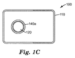
図1A〜1Cは、本開示による皮膚部位の残留アルコールを検出するための代表的な蒸気センサーを示したものである。図1A〜1Cを参照すると、蒸気センサー100は、入口開口部120を有するハウジング110を有している。センサー素子135がハウジング110内に配置され、入口開口部120と流体連通している。管状隔離部材140a(図5Aに斜視図で示される)が、入口開口部120の周囲の環状ボス111に圧力嵌めされることによってハウジング110に取り付けられているが、機械的締結要素又は接着剤などの他の取り付け方法も使用可能であることが考えられる。必要に応じて用いられる多孔質フィルター137が、蒸気センサーに入る埃を遮断するために入口開口部120を覆っている。管状隔離部材140aは、管壁に穴、スリット、又は切欠きのない管で構成されている。管状隔離部材は、圧力嵌めされた別の部材として示されているが、管状隔離部材は代わりにハウジングと一体形成されてもよい。管状隔離部材の代替的な設計が図5B〜5Dに示されている。
1A-1C illustrate an exemplary vapor sensor for detecting residual alcohol at a skin site according to the present disclosure. Referring to FIGS. 1A-1C, the
図5Bを参照すると、管状隔離部材140bは、蒸気センサーに取り付けられる際のその末端開口部147に隣接して複数の切欠き146を有している。1個の切欠きを用いることもできる。
Referring to FIG. 5B, the
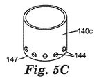
図5Cを参照すると、管状隔離部材140cは、蒸気センサーに取り付けられる際のその末端開口部147に隣接して複数の丸い穴144(すなわち、管の壁を貫通する)を有している。1個の丸い穴を用いることもできる。
Referring to FIG. 5C,
図5Dを参照すると、管状隔離部材140dは、蒸気センサーに取り付けられる際のその末端開口部147に隣接して複数のスロット148を有している。1個のスロットを用いることもできる。
Referring to FIG. 5D, the
隔離部材(管状隔離部材を含む)は、0.25インチ(0.66cm)〜30インチ(76cm)、好ましくは10インチ(25cm)〜14インチ(36cm)、より好ましくは約12インチ(30cm)の長さを有し得るが、これは必要条件ではない。 Isolation members (including tubular isolation members) are 0.25 inches (0.66 cm) to 30 inches (76 cm), preferably 10 inches (25 cm) to 14 inches (36 cm), more preferably about 12 inches (30 cm). However, this is not a requirement.
使い捨て可能又は再使用可能な部品として供給される場合、管状隔離部材は、保護袋に入った滅菌状態で便利よく提供され得る。管状隔離部材は、例えば、固い段ボール紙又はポリエチレン若しくはポリプロピレンなどの低コストのポリマーなどの容易に使い捨て可能な材料で便利よく形成され得る。同様に、蒸気センサー全体を例えば使い捨ての滅菌パッケージに入れて供給することもできる。 When supplied as a disposable or reusable part, the tubular isolation member can be conveniently provided in a sterile state in a protective bag. The tubular isolator can be conveniently formed of an easily disposable material such as, for example, stiff corrugated paper or a low cost polymer such as polyethylene or polypropylene. Similarly, the entire vapor sensor can be supplied, for example, in a disposable sterilization package.
再び図1Bを参照すると、回路基板162上に支持された作動回路160がセンサー素子135と電気的に導通しており、選択されるセンサー素子の種類に応じて、例えば静電容量、反射率、コンダクタンスなどのパラメータの値を測定することが可能である。出力部材170が、作動回路160と通信可能に接続されている。作動回路160は電池121によって電力供給される。作動回路160からの通信を受信することに応じて、出力部材170(図1A〜1Cに液量ディスプレイ(LCD)として示される)上に文字インジケーターが現れ、残留アルコールの濃度が感圧接着剤物品(例えばテープ、貼付剤、包帯、ドレッシング材、又はリード線)との良好な接着性を得るうえで許容される範囲内にあるか否かを表示する。オン/オフスイッチ125(オペレータ制御部)が蒸気センサー100を起動させる。この実施形態では回路基板が示されているが、構成要素は別々に実装されてもよく(例えばハウジングに)、例えば回路基板上の回路トレースの代わりに導線によって接続されてもよい。
Referring again to FIG. 1B, the
センサー素子135は、アルコール蒸気を測定することが可能な任意の種類の感知装置であってよい(例えば容量センサー素子、オプトエレクトロニックセンサー素子、表面プラズモン共鳴センサー素子、弾性表面波センサー素子、光イオン化センサー素子、又はコンダクタンスセンサー素子など)。特定の好ましい実施形態では、センサー素子135は、吸収性誘電材料426が間に配置された第1及び第2の導電性部材(422,424)を含む容量センサー素子435(図4を参照)である。第1の導電性部材は、誘電体基板425(例えば誘電体プラスチックフィルム)上に支持されている。第2の導電性部材424は、アルコール蒸気が容易に浸透できるように充分に多孔質のものであることが好ましい(例えば、熱蒸着された金属フィルム又はプリントされた導電性ナノ粒子インク)。容量センサー素子435は、それぞれ第1及び第2の導電性部材422及び424と接続する付属のリード線442及び444とともに示されている。第1及び第2の導電性部材はここではプレートとして示されているが、容量センサーの技術分野では既知の他の形態(例えば櫛形電気トレース)を有してもよい。
The
必要に応じて、蒸気センサーは、使用者がハウジングを開くことなくセンサー素子を容易に交換できるような構成とすることもできる。例えば、センサー素子は、ハウジングのスロットから交換できるようにしてもよい。 If necessary, the vapor sensor can be configured such that the user can easily replace the sensor element without opening the housing. For example, the sensor element may be exchanged from a slot in the housing.
第1の導電性部材は、任意の適当な導電性材料で構成することができる。充分な全体の導電率が与えられるかぎり、異なる材料(導電性及び/又は非導電性の)組み合わせを、異なる層として、又は混合物として使用することができる。典型的に、第1の導電性部材は、約107Ω/□未満のシート抵抗を有する。第1の導電性部材及び/又は第2の導電性部材を形成するために使用可能な材料の例としては、有機材料、無機材料、金属、合金、並びにこれらの材料のいずれか又はすべてを含む各種の混合物及び複合材料が挙げられる。特定の実施形態では、コーティング(例えば、熱蒸気コーティング又はスパッタコーティング)された金属、若しくは酸化金属、又はこれらの組み合わせを使用することができる。適当な導電性材料としては、例えば、アルミニウム、ニッケル、チタン、スズ、酸化インジウムスズ、金、銀、白金、パラジウム、銅、クロム、カーボンナノチューブ、及びこれらの組み合わせが挙げられる。特定の実施形態では、第1の導電性部材は、金属インク(例えば銀インク又は金インク)を印刷した後に、インクを乾燥させることによって形成することもできる。 The first conductive member can be composed of any appropriate conductive material. Different material (conductive and / or non-conductive) combinations can be used as different layers or as a mixture as long as sufficient overall conductivity is provided. Typically, the first conductive member has a sheet resistance of less than about 10 7 Ω / □. Examples of materials that can be used to form the first conductive member and / or the second conductive member include organic materials, inorganic materials, metals, alloys, and any or all of these materials Various mixtures and composite materials can be mentioned. In certain embodiments, a coated (eg, thermal vapor coated or sputter coated) metal, or metal oxide, or combinations thereof can be used. Suitable conductive materials include, for example, aluminum, nickel, titanium, tin, indium tin oxide, gold, silver, platinum, palladium, copper, chromium, carbon nanotubes, and combinations thereof. In certain embodiments, the first conductive member can also be formed by printing a metal ink (eg, silver ink or gold ink) and then drying the ink.
第2の導電性部材は、アルコール蒸気が透過するものである必要はないが、そうであることが好ましい。第2の導電性部材を形成するために使用可能な材料の例としては、有機材料、無機材料、金属、合金、並びにこれらの材料のいずれか又はすべてを含む各種の混合物及び複合材料が挙げられる。特定の実施形態では、コーティング(例えば、熱蒸気コーティング、スパッタコーティングなど)された金属、若しくは酸化金属、又はこれらの組み合わせを使用することができる。適当な導電性材料としては、例えば、アルミニウム、ニッケル、チタン、スズ、酸化インジウムスズ、金、銀、白金、パラジウム、銅、クロム、カーボンナノチューブ、及びこれらの組み合わせが挙げられる。特定の実施形態では、第2の導電性部材424は、金属インク(例えば銀インク又は金インク)を印刷した後に、インクを乾燥させることによって形成することもできる。充分な全体の導電率及び透過率が与えられるかぎり、異なる材料(導電性及び/又は非導電性の)組み合わせを、異なる層として、又は混合物として使用することができる。典型的に、第2の導電性部材424は、約107Ω/□未満のシート抵抗を有する。
The second conductive member does not need to be permeable to alcohol vapor, but is preferably. Examples of materials that can be used to form the second conductive member include organic materials, inorganic materials, metals, alloys, and various mixtures and composite materials containing any or all of these materials. . In certain embodiments, a coated metal (eg, thermal vapor coating, sputter coating, etc.), or a metal oxide, or a combination thereof can be used. Suitable conductive materials include, for example, aluminum, nickel, titanium, tin, indium tin oxide, gold, silver, platinum, palladium, copper, chromium, carbon nanotubes, and combinations thereof. In certain embodiments, the second
第1の導電性部材は、導電性であるかぎり、任意の厚さ、例えば少なくとも4ナノメートル(nm)〜400nm、又は10nm〜200nmの範囲の厚さであってよい。 The first conductive member may be any thickness as long as it is conductive, for example, a thickness in the range of at least 4 nanometers (nm) to 400 nm, or 10 nm to 200 nm.
いくつかの実施形態では、第1の導電性部材は、曲がりくねった経路を辿ってもよく、必要に応じて、例えば国際公開第2012/141958 A1号(Palazzottoら)に記載されるような加熱素子として機能してもよいが、これは必要条件ではなく、他の構成も考えられる。曲がりくねった経路は、典型的には、加熱することができる面積を大きくするか、かつ/又は加熱速度を増大させる機能を有する。 In some embodiments, the first conductive member may follow a tortuous path and optionally, for example, a heating element as described in WO 2012/141958 A1 (Palazzoto et al.). However, this is not a requirement and other configurations are possible. The tortuous path typically has the function of increasing the area that can be heated and / or increasing the heating rate.
第2の導電性部材は、典型的には、1nm〜100μmの範囲の厚さを有するが、他の厚さが用いられてもよい。 The second conductive member typically has a thickness in the range of 1 nm to 100 μm, although other thicknesses may be used.
例えば第2の導電性部材は、1nm〜100nm、又は更には4nm〜10nmの範囲の厚さを有することができる。厚さがこれよりも大きいと透過性が望ましくない程度に低くなり得るのに対して、厚さがこれよりも小さいと導電性が不充分となるか、かつ/又は第2の導電性部材との電気的接続が困難となり得る。 For example, the second conductive member can have a thickness in the range of 1 nm to 100 nm, or even 4 nm to 10 nm. If the thickness is greater than this, the permeability may be undesirably low, whereas if the thickness is less than this, the conductivity may be insufficient and / or the second conductive member Can be difficult to electrically connect.
別の実施形態では、第1及び第2の導電性部材は、誘電体基板の表面(例えば、単一平面内)上で隣り合わせて、吸収性誘電体材料により分離されるようにして配置されてもよい。この実施形態では、第2の導電性部材は分析物の蒸気に対して透過性である必要はない。このような場合には、第2の導電性部材は、第1の導電性部材としての使用に適した材料を用いて製造することができる。 In another embodiment, the first and second conductive members are arranged side by side on the surface of the dielectric substrate (eg, in a single plane) and separated by the absorbent dielectric material. Also good. In this embodiment, the second conductive member need not be permeable to analyte vapor. In such a case, the second conductive member can be manufactured using a material suitable for use as the first conductive member.
吸収性誘電体材料は、微多孔質でありかつ少なくとも1つの分析物をその内部に吸収することが可能な材料であることが好ましい。これに関連して、「微多孔質」及び「微多孔性」なる用語は、材料が、相当量の内部の相互接続された細孔体積を有し、平均孔径(例えば、吸着等温線法によって特性評価される)が約100nm未満、典型的には約10nm未満であることを意味する。このような微多孔性により、有機分析物の分子(存在する場合)が、材料の内部細孔体積に浸透して内部孔の中に定着することが可能となる。内部の細孔中のかかる分析物の存在は、材料の誘電特性を変化させ得るものであり、これにより誘電率(又は他の任意の適当な電気的特性)の変化が認められ得る。 The absorbing dielectric material is preferably a material that is microporous and capable of absorbing at least one analyte therein. In this context, the terms “microporous” and “microporous” mean that the material has a substantial amount of internal interconnected pore volume and has an average pore size (eg by adsorption isotherm). Characterized) is less than about 100 nm, typically less than about 10 nm. Such microporosity allows organic analyte molecules (if present) to penetrate into the internal pore volume of the material and settle into the internal pores. The presence of such analytes in the internal pores can change the dielectric properties of the material, which can be seen to change the dielectric constant (or any other suitable electrical property).
特定の実施形態では、吸収性誘電体材料は、いわゆる固有微多孔性ポリマー(PIM)を含む。PIMは、ポリマー鎖の非効率的な充填によるナノメートルスケールの孔を有するポリマー材料である。例えば、Chemical Communications,2004,(2),pp.230〜231,Budd et al.には、固い及び/又は歪んだモノマー構成単位間のジベンゾジオキサン結合を含有する、一連の固有微多孔性の材料が報告されている。このポリマーのファミリーの代表的なメンバーとしては、スキーム1(下記)に従って表1に示される成分A(例えば、A1、A2、又はA3)と成分B(例えば、B1、B2、又はB3)との縮合によって生成されるものが挙げられる。 In certain embodiments, the absorbing dielectric material comprises a so-called intrinsic microporous polymer (PIM). PIM is a polymeric material with nanometer scale pores due to inefficient filling of polymer chains. For example, in Chemical Communications, 2004, (2), pp. 230-231, Budd et al. Reported a series of inherently microporous materials containing dibenzodioxane linkages between hard and / or distorted monomeric building blocks. Representative members of this polymer family include component A (eg, A1, A2, or A3) and component B (eg, B1, B2, or B3) shown in Table 1 according to Scheme 1 (below). What is produced | generated by condensation is mentioned.

更に適当な成分A及びB、並びに得られる固有微多孔性のポリマーは、当該技術分野では既知のものであり、例えば、BuddらによりJournal of Materials Chemistry,2005,Vol.15,pp.1977〜1986に、McKeownらによりCHEMISTRY,A European Journal,2005,Vol.11,pp.2610〜2620に、GhanemらによりMacromolecules,2008,vol.41,pp.1640〜1646に、GhanemらによりAdvanced Materials,2008,vol.20,pp.2766〜2771に、CartaらによりOrganic Letters,2008,vol.10(13),pp.2641〜2643に、国際公開第2005/012397A2号(McKeownら)に、また、米国特許出願公開第2006/0246273号(McKeownら)に報告されている。かかるポリマーは、例えば、A1(5,5’,6,6’−テトラヒドロキシ−3,3,3’,3’−テトラメチル−1,1’−スピロビスインダン)などのビス−カテコールを、例えば、B1(テトラフルオロテレフタロニトリル)などのフッ素化アレーンと塩基性条件下で反応させる逐次重合によって合成することができる。得られるポリマーの主鎖の固さ及びねじ曲がった性質のため、これらのポリマーは、固体状態では密に充填することができず、したがって、少なくとも10パーセントの自由体積を有し、固有微多孔性である。 Further suitable components A and B and the resulting inherently microporous polymers are known in the art, see, for example, Budd et al., Journal of Materials Chemistry, 2005, Vol. 15, pp. 1977-1986, McKeown et al., CHEMISTRY, A European Journal, 2005, Vol. 11, pp. 2610-2620, Ghanem et al., Macromolecules, 2008, vol. 41, pp. 1640-1646, Ghanem et al., Advanced Materials, 2008, vol. 20, pp. 2766-2771, by Carta et al., Organic Letters, 2008, vol. 10 (13), pp. 2641-2643, International Publication No. 2005 / 012397A2 (McKeown et al.), And US Patent Application Publication No. 2006/0246273 (McKeown et al.). Such polymers include, for example, bis-catechols such as A1 (5,5 ′, 6,6′-tetrahydroxy-3,3,3 ′, 3′-tetramethyl-1,1′-spirobisindane), For example, it can be synthesized by sequential polymerization in which a fluorinated arene such as B1 (tetrafluoroterephthalonitrile) is reacted under basic conditions. Due to the stiffness and twisted nature of the resulting polymer backbone, these polymers cannot be tightly packed in the solid state and thus have at least 10 percent free volume and inherent microporosity. It is.
PIMは、他の材料と混合することができる。例えば、PIMは、それ自体が吸収性誘電体材料ではない材料と混合することができる。分析物応答には寄与しないものの、このような材料は他の理由のために有用であり得る。例えば、このような材料は、優れた機械的特性などを有するPIM含有層の形成を可能とし得る。一実施形態では、PIMは、他の材料とともに一般的な溶媒に溶解して均質な溶液を形成し、これをキャスティングして、PIM及び他のポリマーの両方を含む吸収性誘電体ブレンド層を形成することができる。PIMはまた、吸収性誘電体材料である材料(例えば、ゼオライト、活性炭、シリカゲル、超架橋ポリマーネットワークなど)とブレンドしてもよい。かかる材料は、PIM材料を含む溶液中に懸濁された不溶性材料を含み得る。かかる溶液/懸濁液をコーティング及び乾燥させることによって、PIM材料及び更なる吸収性誘電体材料の両方を含む複合吸収性誘電体層が与えられる。 PIM can be mixed with other materials. For example, the PIM can be mixed with a material that is not itself an absorptive dielectric material. While not contributing to the analyte response, such materials may be useful for other reasons. For example, such materials may allow for the formation of PIM-containing layers that have excellent mechanical properties and the like. In one embodiment, the PIM dissolves in a common solvent with other materials to form a homogeneous solution that is cast to form an absorptive dielectric blend layer that includes both the PIM and other polymers. can do. The PIM may also be blended with materials that are absorbing dielectric materials (eg, zeolites, activated carbon, silica gel, hypercrosslinked polymer networks, etc.). Such materials may include insoluble materials suspended in a solution containing PIM material. Coating and drying such a solution / suspension provides a composite absorbent dielectric layer that includes both a PIM material and a further absorbent dielectric material.
PIMは、典型的には、例えばテトラヒドロフランなどの有機溶媒に可溶性であり、このため、溶液からフィルムとしてキャスティングすることができる(例えば、スピンコーティング、ディップコーティング、又はバーコーティングによって)。しかし、これらのポリマーの溶液から形成されるフィルムの特徴(得られる厚さ、光学的透明度、及び/又は外観)は、フィルムのキャスティングに使用される溶媒又は溶媒系に応じて著しく異なり得る。例えば、本明細書に述べられる蒸気センサーで使用するのに望ましい性質を備えたフィルムを作製するためには、より分子量の大きな固有微多孔性ポリマーを、比較的一般的でない溶媒(例えば、シクロヘキセンオキシド、クロロベンゼン、又はテトラヒドロピラン)からキャスティングしなければならない場合がある。溶液コーティング法に加えて、検出層は他の任意の適当な方法によって第1の導電性部材に塗布することができる。 PIM is typically soluble in organic solvents such as, for example, tetrahydrofuran and can therefore be cast as a film from solution (eg, by spin coating, dip coating, or bar coating). However, the characteristics (thickness obtained, optical clarity, and / or appearance) of films formed from solutions of these polymers can vary significantly depending on the solvent or solvent system used for film casting. For example, to make a film with desirable properties for use in the vapor sensors described herein, a higher molecular weight intrinsic microporous polymer may be combined with a relatively uncommon solvent (eg, cyclohexene oxide). , Chlorobenzene, or tetrahydropyran) may have to be cast. In addition to the solution coating method, the detection layer can be applied to the first conductive member by any other suitable method.
PIMを吸収性誘電体層を構成するように堆積する(例えば、コーティングする)か又は他の形で形成した後、材料を、例えばビス(ベンゾニトリル)二塩化パラジウム(II)などの適当な架橋剤を使用して架橋することができる。このプロセスは、吸収性誘電体層を有機溶媒に対して不溶性とするか、かつ/又は、特定の用途において望まれる場合がある耐久性、耐摩耗性といった特定の物理的性質を向上させることができる。 After the PIM is deposited (eg, coated) or otherwise formed to constitute an absorbing dielectric layer, the material is then cross-linked, such as bis (benzonitrile) palladium (II) dichloride. It can be cross-linked using an agent. This process can make the absorptive dielectric layer insoluble in organic solvents and / or improve certain physical properties such as durability, abrasion resistance that may be desired in certain applications. it can.
PIMは、材料が大きく膨潤するか又は他の形で物理的特性の顕著な変化を示す程度に液体の水を吸収することがないよう、疎水性のものとすることができる。かかる疎水性は、水の存在に対する感度が比較的低い有機分析物センサー素子を提供するうえで有用である。しかしながら、材料は特定の目的のためには比較的極性の部分を含んでもよい。 The PIM can be hydrophobic so that the material does not swell significantly or otherwise absorbs liquid water to the extent that it exhibits significant changes in physical properties. Such hydrophobicity is useful in providing organic analyte sensor elements that are relatively insensitive to the presence of water. However, the material may include relatively polar portions for specific purposes.
一実施形態では、吸収性誘電体材料は連続的なマトリックスを含む。かかるマトリックスは、材料の固体部分が連続的に相互接続された構造体(例えば、コーティング、層など)として定義される(上記に述べたような多孔性の存在、又は下記に述べる任意の添加物の存在とは関係なく)。すなわち、連続的なマトリックスは、粒子(例えば、ゼオライト、活性炭、及びカーボンナノチューブ)の凝集体からなる構造体とは区別される。例えば、溶液から堆積される層又はコーティングは、典型的に連続的なマトリックスを構成する(コーティング自体がパターン化された形で塗布されるか、かつ/又は粒子状添加剤を含む場合であっても)。粉末の噴霧、分散液(例えばラテックス)のコーティング及び乾燥によって、又はゾルゲル混合物のコーティング及び乾燥によって堆積された粒子の集合は、連続的なネットワークを構成しない場合がある。しかしながら、かかるラテックス、ゾルゲルなどの層が、個々の粒子がもはや識別不可能であり、異なる粒子から得られた構造体の各領域を識別することも不可能であるように固化され得る場合に、かかる層はひいては連続的マトリックスと見なされ得る。 In one embodiment, the absorbing dielectric material includes a continuous matrix. Such a matrix is defined as a structure (eg, coating, layer, etc.) in which solid portions of the material are continuously interconnected (the presence of porosity as described above, or any additive described below) Regardless of the existence of). That is, a continuous matrix is distinguished from a structure composed of aggregates of particles (eg, zeolite, activated carbon, and carbon nanotubes). For example, a layer or coating deposited from a solution typically constitutes a continuous matrix (if the coating itself is applied in a patterned form and / or contains particulate additives. Also). Aggregates of particles deposited by powder spraying, dispersion (eg latex) coating and drying, or by sol-gel mixture coating and drying may not constitute a continuous network. However, when such latex, sol-gel, etc. layers can be solidified such that individual particles are no longer distinguishable and it is also impossible to identify regions of the structure obtained from different particles, Such a layer can then be regarded as a continuous matrix.
容量センサー素子は、回路製造における一般的な方法を用いて(例えば、蒸着法によって、又はフォトリソグラフィー法によって)、例えば、誘電体基板上に第1の導電性部材を配置することによって(例えば、蒸着法によって、又はフォトリソグラフィー法によって)製造可能である。 The capacitive sensor element may be formed using a common method in circuit manufacturing (for example, by vapor deposition or photolithography), for example, by disposing a first conductive member on a dielectric substrate (for example, It can be produced by vapor deposition or by photolithography.
次に、適当な有機溶媒中の微多孔性誘電体材料を、第1の導電性部材上にコーティングし、溶媒を除去する。最後に、第2の導電性部材を微多孔性誘電体材料上に配置する(例えば、蒸着法、又はデジタル印刷法(例えばインクジェット印刷法)を用いたスクリーン印刷などの印刷法によって)。 Next, a microporous dielectric material in a suitable organic solvent is coated on the first conductive member and the solvent is removed. Finally, the second conductive member is disposed on the microporous dielectric material (eg, by a printing method such as vapor deposition or screen printing using a digital printing method (eg, inkjet printing)).
図6は、センサー素子135と出力部材170の動作を連係するための代表的な作動回路600の一構成を示す。制御モジュール160は、センサー素子135と電気的に接続されている。制御モジュール160は、少なくとも1つの出力部材170及び必要に応じて用いられるオペレータ制御部125に通信可能に接続されている(例えば電気回路により、又は無線通信を介して)。作動回路は、電源121(例えば電池又は電源コード)によって電力供給される。存在する場合には、必要に応じて用いられるファン150も制御モジュール160によって便利よく制御することができる。他の作動回路の構成も可能であり、当業者の能力の範囲内にあることが認識されよう。
FIG. 6 shows a configuration of a
容量型センサー素子、その製造、較正、容量型センサー素子を含む蒸気センサー、及び有機蒸気(例えばアルコール)濃度を測定するためのその使用に関する更なる詳細については、国際公開第2012/141883 A1号(Palazzottoら)、同第2012/050686 A1号(Palazzottoら)、同第2012/141894 A1号(Kangら)、同第2013/090188 A1号(Gryskaら)、並びに米国特許出願公開第2011/0045601 A1号(Gryskaら)及び同第2010/0277740 A1号(Hulteenら)に見ることができる。 For further details regarding capacitive sensor elements, their manufacture, calibration, vapor sensors including capacitive sensor elements, and their use for measuring organic vapor (eg alcohol) concentrations, see WO 2012/141883 A1 ( Palazzotto et al.), 2012/050686 A1 (Palazzoto et al.), 2012/141894 A1 (Kang et al.), 2013/090188 A1 (Gryska et al.), And US Patent Application Publication No. 2011/0045601 A1. No. (Gryska et al.) And 2010/0277740 A1 (Hulten et al.).
他の種類のセンサー素子、その製造、他の種類のセンサー素子を含む蒸気センサー、及び有機蒸気(例えばアルコール)濃度を測定するためのその使用に関する更なる詳細については、国際公開第2012/174099 A1号(Kangら、表面プラズモン共鳴センサー素子に関するもの)及び同第2012/141883 A1号(Palazzottoら、容量及びオプトエレクトニックセンサー素子に関するもの)に見ることができる。 For further details regarding other types of sensor elements, their manufacture, vapor sensors including other types of sensor elements, and their use for measuring organic vapor (eg alcohol) concentrations, see WO 2012/174099 A1. No. (Kang et al., Relating to surface plasmon resonance sensor elements) and 2012/141883 A1 (Parazzoto et al., Relating to capacitance and optoelectronic sensor elements).
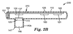
図2A〜2Cは、本開示による皮膚部位の残留アルコールを検出するための代表的な蒸気センサーの別の実施形態を示したものである。図2A〜2Cを参照すると、蒸気センサー200は、入口開口部120を有するハウジング110を含む。センサー素子135がハウジング110内に配置され、入口開口部120と流体連通している。必要に応じて用いられる多孔質フィルター137が、蒸気センサーに入る埃を遮断するために入口開口部120を覆っている。図示されていないが、出口開口部を覆う第2の多孔質フィルターが含まれてもよいが、これは必要条件ではない。この第2の多孔質フィルターは、例えば入口開口部を覆う多孔質フィルターと同じか又は同様のものであってよい。ファン150が、入口開口部120から入る空気をハウジングを通って出口開口部151に送る。管状隔離部材140b(図5Bに斜視図で示される)が、入口開口部120の周囲の環状ボス111に圧力嵌めされることによってハウジング110に取り付けられている。回路基板162上に支持された作動回路160がセンサー素子135と電気的に導通している。作動回路160は電池121によって電力供給される。出力部材270は、アルコール濃度が許容可能に低い場合に操作者に知らせるインジケーターライト272(赤)、274(緑)を含む。
2A-2C illustrate another embodiment of an exemplary vapor sensor for detecting residual alcohol at a skin site according to the present disclosure. With reference to FIGS. 2A-2C, the
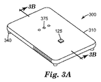
図3A〜3Cは、本開示による皮膚部位の残留アルコールを検出するための代表的な蒸気センサーの別の実施形態を示したものである。図3A〜3Cを参照すると、蒸気センサー300は、入口開口部120を有するハウジング110を含む。センサー素子135がハウジング110内に配置され、入口開口部120と流体連通している。必要に応じて用いられる多孔質フィルター137が、蒸気センサーに入る埃を遮断するために入口開口部120を覆っている。ファン150が、入口開口部120から入る空気をハウジングを通って出口開口部151に送る。管状隔離部材340がハウジングに取り付けられている(例えば接着剤により)。回路基板162上に支持された作動回路160がセンサー素子135と電気的に導通している。作動回路160は電池121によって電力供給される。出力部材370は、アルコール濃度が許容可能に低いことを操作者に知らせる可聴音を音声穴375から発する音声発声装置(例えばスピーカー、アラーム、バイブレーター、又はホーン)を含む。
3A-3C illustrate another embodiment of an exemplary vapor sensor for detecting residual alcohol at a skin site according to the present disclosure. Referring to FIGS. 3A-3C, the
本開示による蒸気センサーは、例えば手術を行う前の皮膚部位又はカテーテルを挿入する前の皮膚部位などの皮膚部位の、例えば残留アルコールの存在を検出するうえで有用である。皮膚部位のアルコールの有無を判定するには、蒸気センサーの隔離部材は、対象となる皮膚部位に隣接して患者と接触させられる。測定を容易にするため、対象となる皮膚部位はできるだけ入口開口部の近くに配置されることが好ましい。接触は皮膚に対して行われることが好ましいが、接触は、望ましい及び/又は必要な場合には患者の被覆された(例えばドレッシング材及び/又は衣類によって被覆された)領域に対して行われてもよい。典型的な使用では、本開示による蒸気センサーは、アルコール濃度の信頼できる測定値が与えられるだけの充分な時間(例えば1〜10秒間)にわたって皮膚部位と接触状態に置かれる。検出器が、接着物品を皮膚部位に適用できるだけアルコール蒸気濃度が充分に低いと判定したならば、出力モジュールが使用者に通知し、蒸気センサーを取り外して接着ドレッシング、テープ、及び/又は包帯(例えばカテーテルの挿入にともなうもの)を、アルコールの存在によって接着力が低下する恐れなく適用することができる。 A vapor sensor according to the present disclosure is useful for detecting the presence of, for example, residual alcohol in a skin site, such as a skin site prior to performing surgery or a skin site prior to insertion of a catheter. To determine the presence or absence of alcohol on the skin site, the isolation member of the vapor sensor is brought into contact with the patient adjacent to the target skin site. In order to facilitate the measurement, the target skin site is preferably located as close to the entrance opening as possible. While contact is preferably made to the skin, contact is made to the patient's covered area (eg, covered by dressing and / or clothing) if desired and / or necessary. Also good. In typical use, a vapor sensor according to the present disclosure is placed in contact with a skin site for a sufficient time (eg, 1-10 seconds) to provide a reliable measurement of alcohol concentration. If the detector determines that the alcohol vapor concentration is low enough to apply the adhesive article to the skin site, the output module notifies the user and removes the vapor sensor to provide an adhesive dressing, tape, and / or bandage (eg, (With the insertion of the catheter) can be applied without fear of the adhesive force being reduced by the presence of alcohol.
図7は、皮膚部位790のアルコールの濃度を測定するための蒸気センサー200の適用及び使用を示したものであり、管状隔離部材140bの末端147に隣接した切欠き146によって、皮膚部位790に隣接する周囲雰囲気をファン150によって入口開口部内に連続的に引き込み、センサー素子135によって測定することで周囲雰囲気中のアルコール蒸気の含有量を決定し、アルコール蒸気の濃度に応じて赤(停止)又は緑(続行)のインジケーターライトを点灯することが可能となっている。
FIG. 7 illustrates the application and use of the
それよりも低い値では、続行を促す指示が蒸気センサーから操作者に送信されるアルコール蒸気の特定の濃度は任意の濃度であってよいが、好ましくはこの濃度は約1000重量ppm未満であり、ただしこれは必要条件ではない。 At lower values, the specific concentration of alcohol vapor that prompts the operator to continue from the vapor sensor may be any concentration, but preferably this concentration is less than about 1000 ppm by weight, This is not a requirement.
有利な点として、本開示による蒸気センサーを使用してアルコール蒸気濃度を評価するのに要する時間は、当該技術分野における現状での慣例の1つにおけるように3分間が経過するのを待つよりも数分早くなり得る(典型的には早い)。 Advantageously, the time required to evaluate alcohol vapor concentration using a vapor sensor according to the present disclosure is greater than waiting for 3 minutes to pass as in one of the current practice in the art. Can be a few minutes earlier (typically faster).
本開示の選択された実施形態
第1の実施形態では、本開示は、皮膚部位の残留アルコールを検出するための蒸気センサーであって、
ハウジングであって、ハウジングの内部に延びる入口開口部を含むハウジングと、
ハウジング内に配置され、入口開口部と流体連通したセンサー素子と、
ハウジングに隣接して配置される少なくとも1つの隔離部材であって、入口開口部と皮膚部位との間に隙間を維持するように配置された、少なくとも1つの隔離部材と、
センサー素子と電気的に導通し、センサー素子のパラメータを検出することが可能な作動回路であって、パラメータがアルコール濃度と相関したものである、作動回路と、
作動回路と通信可能に接続された少なくとも1つの出力部材であって、作動回路からの通信を受信すると、皮膚部位に隣接した周囲雰囲気中のアルコール蒸気の濃度に関して操作者に示される検知出力を生成するようになっている、少なくとも1つの出力部材と、を含む、蒸気センサーを提供する。
Selected Embodiments of the Present Disclosure In a first embodiment, the present disclosure is a vapor sensor for detecting residual alcohol at a skin site, comprising:
A housing comprising an inlet opening extending into the housing;
A sensor element disposed in the housing and in fluid communication with the inlet opening;
At least one isolation member disposed adjacent to the housing, the at least one isolation member positioned to maintain a gap between the inlet opening and the skin site;
An actuation circuit that is in electrical communication with the sensor element and is capable of detecting a parameter of the sensor element, wherein the parameter is correlated with the alcohol concentration;
At least one output member communicatively connected to the actuation circuit, and upon receipt of the communication from the actuation circuit, generates a sensing output that is indicated to the operator with respect to the concentration of alcohol vapor in the ambient atmosphere adjacent to the skin site A vapor sensor comprising: at least one output member adapted to:
第2の実施形態では、本開示は、吸収性誘電体材料が、固有微多孔性のポリマーを含む、第1の実施形態に記載の蒸気センサーを提供する。 In a second embodiment, the present disclosure provides a vapor sensor as described in the first embodiment, wherein the absorbing dielectric material comprises an intrinsic microporous polymer.
第3の実施形態では、本開示は、ハウジングが、ハウジング内部において入口開口部と流体連通した出口開口部を更に含む、第1又は第2の実施形態に記載の蒸気センサーを提供する。 In a third embodiment, the present disclosure provides a vapor sensor according to the first or second embodiment, wherein the housing further includes an outlet opening in fluid communication with the inlet opening within the housing.
第4の実施形態では、本開示は、入口開口部から出口開口部に気体を移動させるための装置を更に含む、第3の実施形態に記載の蒸気センサーを提供する。 In a fourth embodiment, the present disclosure provides the vapor sensor of the third embodiment, further comprising an apparatus for moving gas from the inlet opening to the outlet opening.
第5の実施形態では、本開示は、少なくとも1つの隔離部材が圧力嵌めによってハウジングに着脱可能に取り付けられた、第1〜第4の実施形態のいずれか1つに記載の蒸気センサーを提供する。 In a fifth embodiment, the present disclosure provides the vapor sensor of any one of the first to fourth embodiments, wherein at least one isolation member is removably attached to the housing by a press fit. .
第6の実施形態では、本開示は、少なくとも1つの隔離部材がハウジングと一体形成された、第1〜第5の実施形態のいずれか1つに記載の蒸気センサーを提供する。 In a sixth embodiment, the present disclosure provides the steam sensor according to any one of the first to fifth embodiments, wherein at least one isolation member is integrally formed with the housing.
第7の実施形態では、本開示は、少なくとも1つの隔離部材が、基端開口部、壁部、及び基端開口部の反対側の末端開口部を有する管を含み、基端開口部がハウジングと接触して入口ポートを包囲し、壁部が、少なくとも1つの切欠き、少なくとも1つの穴、又はこれらの組み合わせを有する、第1〜第6の実施形態のいずれか1つに記載の蒸気センサーを提供する。 In a seventh embodiment, the present disclosure provides that the at least one isolation member includes a tube having a proximal opening, a wall, and a distal opening opposite the proximal opening, the proximal opening being a housing. The vapor sensor according to any one of the first to sixth embodiments, wherein the vapor sensor is in contact with the inlet port and the wall has at least one notch, at least one hole, or a combination thereof. I will provide a.
第8の実施形態では、本開示は、少なくとも1つの隔離部材が、少なくとも3つの隔離部材を含む、第1〜第6の実施形態のいずれか1つに記載の蒸気センサーを提供する。 In an eighth embodiment, the present disclosure provides the vapor sensor according to any one of the first to sixth embodiments, wherein the at least one isolation member includes at least three isolation members.
第9の実施形態では、本開示は、残留アルコールを検出する方法であって、
皮膚部位の残留アルコールを検出するための蒸気センサーを用意する工程であって、蒸気センサーが、
ハウジングであって、ハウジングの内部に延びる入口開口部を含むハウジングと、
ハウジング内に配置され、入口開口部と流体連通したセンサー素子と、
ハウジングに隣接して配置される少なくとも1つの隔離部材であって、入口開口部と皮膚部位との間に隙間を維持するように配置された、少なくとも1つの隔離部材と、
センサー素子と電気的に導通し、センサー素子のパラメータを検出することが可能な作動回路であって、パラメータがアルコール濃度と相関したものである、作動回路と、
作動回路と通信可能に接続された少なくとも1つの出力部材であって、作動回路からの通信を受信すると、皮膚部位に隣接した周囲雰囲気中のアルコール蒸気の濃度に関して操作者に示される検知出力を生成するようになっている、少なくとも1つの出力部材と、を含むものである、工程と、
入口開口部が少なくとも1つの隔離部材によって皮膚部位から分離されるように皮膚部位に隣接して蒸気センサーを配置する工程と、
センサー素子が周囲雰囲気に曝露されるように皮膚部位に隣接した周囲雰囲気を入口開口部内に導入する工程と、
センサー素子のパラメータの値を測定する工程と、
パラメータの値に少なくとも部分的に基づいて、少なくとも1つの出力部材に検知出力を生成させる工程と、を含む、方法を提供する。
In a ninth embodiment, the present disclosure is a method for detecting residual alcohol, comprising:
A step of preparing a vapor sensor for detecting residual alcohol in the skin site, wherein the vapor sensor is
A housing comprising an inlet opening extending into the housing;
A sensor element disposed in the housing and in fluid communication with the inlet opening;
At least one isolation member disposed adjacent to the housing, the at least one isolation member positioned to maintain a gap between the inlet opening and the skin site;
An actuation circuit that is in electrical communication with the sensor element and is capable of detecting a parameter of the sensor element, wherein the parameter is correlated with the alcohol concentration;
At least one output member communicatively connected to the actuation circuit, and upon receipt of the communication from the actuation circuit, generates a sensing output that is indicated to the operator with respect to the concentration of alcohol vapor in the ambient atmosphere adjacent to the skin site At least one output member adapted to: a process comprising:
Positioning the vapor sensor adjacent to the skin site such that the inlet opening is separated from the skin site by at least one isolation member;
Introducing an ambient atmosphere adjacent to the skin site into the inlet opening so that the sensor element is exposed to the ambient atmosphere;
Measuring the parameter value of the sensor element;
Causing at least one output member to generate a sensing output based at least in part on the value of the parameter.
第10の実施形態では、本開示は、蒸気センサーが皮膚部位に隣接して配置される少し前に皮膚部位がアルコールベースの製剤で処理される、第9の実施形態に記載の方法を提供する。 In a tenth embodiment, the present disclosure provides the method of the ninth embodiment, wherein the skin site is treated with an alcohol-based formulation shortly before the vapor sensor is placed adjacent to the skin site. .
第11の実施形態では、本開示は、センサー素子が、第1の導電性部材、第2の導電性部材、及び第1の導電性部材と第2の導電性部材との間に挟まれた吸収性誘電体材料を含む、第9又は第10の実施形態に記載の方法を提供する。 In an eleventh embodiment, the present disclosure is directed to a sensor element sandwiched between a first conductive member, a second conductive member, and a first conductive member and a second conductive member. A method according to the ninth or tenth embodiment is provided comprising an absorptive dielectric material.
第12の実施形態では、本開示は、吸収性誘電体材料が固有微多孔性のポリマーを含む、第9〜11の実施形態のいずれか1つに記載の方法を提供する。 In a twelfth embodiment, the present disclosure provides a method according to any one of the ninth to eleventh embodiments, wherein the absorbent dielectric material comprises an inherently microporous polymer.
第13の実施形態では、本開示は、ハウジングが、ハウジング内部において入口開口部と流体連通した出口開口部を更に含む、第9〜第12の実施形態のいずれか1つに記載の方法を提供する。 In the thirteenth embodiment, the present disclosure provides the method of any one of the ninth to twelfth embodiments, wherein the housing further includes an outlet opening in fluid communication with the inlet opening within the housing. To do.
第14の実施形態では、本開示は、入口開口部から出口開口部に気体を移動させるための装置を更に含む、第13の実施形態に記載の方法を提供する。 In a fourteenth embodiment, the present disclosure provides the method of the thirteenth embodiment, further comprising an apparatus for moving gas from the inlet opening to the outlet opening.
第15の実施形態では、本開示は、少なくとも1つの隔離部材が圧力嵌めによってハウジングに着脱可能に取り付けられた、第9〜第14の実施形態のいずれか1つに記載の方法を提供する。 In a fifteenth embodiment, the present disclosure provides the method of any one of the ninth to fourteenth embodiments, wherein at least one isolation member is removably attached to the housing by a press fit.
第16の実施形態では、本開示は、少なくとも1つの隔離部材がハウジングと一体形成された、第9〜第15の実施形態のいずれか1つに記載の方法を提供する。 In the sixteenth embodiment, the present disclosure provides the method of any one of the ninth to fifteenth embodiments, wherein the at least one isolation member is integrally formed with the housing.
第17の実施形態では、本開示は、少なくとも1つの隔離部材が、基端開口部、壁部、及び基端開口部の反対側の末端開口部を有する管を含み、基端開口部がハウジングと接触して入口ポートを包囲し、壁部が、少なくとも1つの切欠き、少なくとも1つの穴、又はこれらの組み合わせを有する、第9〜第16の実施形態のいずれか1つに記載の方法を提供する。 In a seventeenth embodiment, the present disclosure provides that the at least one isolation member includes a tube having a proximal opening, a wall, and a distal opening opposite the proximal opening, the proximal opening being a housing The method according to any one of the ninth to sixteenth embodiments, wherein the method further comprises enclosing the inlet port and the wall has at least one notch, at least one hole, or a combination thereof. provide.
第18の実施形態では、本開示は、少なくとも1つの隔離部材が、少なくとも3つの隔離部材を含む、第9〜第17の実施形態のいずれか1つに記載の方法を提供する。 In an eighteenth embodiment, the present disclosure provides the method of any one of the ninth to seventeenth embodiments, wherein the at least one isolation member includes at least three isolation members.
特許証のための上記の出願において引用された、引用文献、特許、又は特許出願はいずれも、一貫した形でそれらの全容を本明細書に参照により援用するものである。援用された参照文献の部分と本願の部分との間に不一致又は矛盾がある場合、先行する記述の情報が優先されるものとする。上記の説明は、特許請求される開示内容を当業者をして実施することを可能ならしめる目的で与えられるものであり、本開示の範囲を限定するものとして解釈すべきではなく、本開示の範囲は、特許請求の範囲及びその均等物によって定義されるものである。 All cited references, patents, or patent applications cited in the above applications for patents are hereby incorporated by reference in their entirety in their entirety. If there is a discrepancy or contradiction between the part of the incorporated reference and the part of the present application, the information in the preceding description shall prevail. The above description is provided to enable any person skilled in the art to implement the claimed disclosure and should not be construed as limiting the scope of the present disclosure. The scope is defined by the claims and their equivalents.
Claims (2)
ハウジングであって、該ハウジングの内部に延びる入口開口部を含むハウジングと、
前記ハウジング内に配置され、前記入口開口部と流体連通したセンサー素子であって、第1の導電性部材、第2の導電性部材、及び前記第1の導電性部材と前記第2の導電性部材との間に挟まれた吸収性誘電体材料を含むセンサー素子と、
前記ハウジングに隣接して配置され、前記入口開口部と前記皮膚部位との間に隙間を維持するように配置された少なくとも1つの隔離部材であって、基端開口部と、壁部と、前記基端開口部とは反対側の末端開口部とを有する管を含み、前記基端開口部が前記ハウジングと接触し前記入口開口部を包囲し、前記壁部が、前記皮膚部位に隣接した周囲雰囲気を前記壁部を通じて前記入口開口部に引き込ませる、前記末端開口部に近接する1つ以上の開口部を含む、少なくとも1つの隔離部材と、
前記センサー素子と電気的に導通し、前記センサー素子のパラメータを検出することが可能な作動回路であって、前記パラメータがアルコール濃度と相関したものである、作動回路と、
前記作動回路と通信可能に接続された少なくとも1つの出力部材であって、前記作動回路からの通信を受信すると、前記皮膚部位に隣接した周囲雰囲気中のアルコール蒸気の濃度に関して操作者に示される検知出力を生成するようになっている、少なくとも1つの出力部材と、を含む、蒸気センサー。 A vapor sensor for detecting residual alcohol in the skin area,
A housing comprising an inlet opening extending into the housing;
A sensor element disposed within the housing and in fluid communication with the inlet opening, the first conductive member, the second conductive member, and the first conductive member and the second conductive member. A sensor element comprising an absorptive dielectric material sandwiched between members;
At least one isolation member disposed adjacent to the housing and disposed to maintain a gap between the inlet opening and the skin site, comprising : a proximal opening; a wall; A tube having a distal opening opposite to the proximal opening, wherein the proximal opening contacts the housing and surrounds the inlet opening, and the wall is adjacent to the skin site At least one isolation member including one or more openings proximate to the end opening that causes atmosphere to be drawn through the wall into the inlet opening ;
An operating circuit that is in electrical communication with the sensor element and capable of detecting a parameter of the sensor element, wherein the parameter is correlated with alcohol concentration;
At least one output member communicatively connected to the actuation circuit, the detection being indicated to the operator with respect to the concentration of alcohol vapor in the ambient atmosphere adjacent to the skin site upon receipt of communication from the actuation circuit A vapor sensor comprising: at least one output member adapted to generate an output.
皮膚部位の残留アルコールを検出するための蒸気センサーを用意する工程であって、前記蒸気センサーが、
ハウジングであって、該ハウジングの内部に延びる入口開口部を含むハウジングと、
前記ハウジング内に配置され、前記入口開口部と流体連通したセンサー素子と、
前記ハウジングに隣接して配置され、前記入口開口部と前記皮膚部位との間に隙間を維持するように配置された少なくとも1つの隔離部材であって、基端開口部と、壁部と、前記基端開口部とは反対側の末端開口部とを有する管を含み、前記基端開口部が前記ハウジングと接触し前記入口開口部を包囲し、前記壁部が、前記皮膚部位に隣接した周囲雰囲気を前記壁部を通じて前記入口開口部に引き込ませる、前記末端開口部に近接する1つ以上の開口部を含む、少なくとも1つの隔離部材と、
前記センサー素子と電気的に導通し、前記センサー素子のパラメータを検出することが可能な作動回路であって、前記パラメータがアルコール濃度と相関したものである、作動回路と、
前記作動回路と通信可能に接続された少なくとも1つの出力部材であって、前記作動回路からの通信を受信すると、前記皮膚部位に隣接した周囲雰囲気中のアルコール蒸気の濃度に関して操作者に示される検知出力を生成するようになっている、少なくとも1つの出力部材と、を含むものである、工程と、
前記入口開口部が前記少なくとも1つの隔離部材によって前記皮膚部位から分離されるように前記皮膚部位に隣接して前記蒸気センサーを配置する工程と、
前記センサー素子が周囲雰囲気に曝露されるように、前記皮膚部位に隣接した周囲雰囲気を前記壁部の前記開口部を通じて前記入口開口部内に導入する工程と、
前記センサー素子の前記パラメータの値を測定する工程と、
前記パラメータの値に少なくとも部分的に基づいて、前記少なくとも1つの出力部材に前記検知出力を生成させる工程と、を含む、方法。 A method for detecting residual alcohol, comprising:
Providing a vapor sensor for detecting residual alcohol in the skin site, wherein the vapor sensor comprises:
A housing comprising an inlet opening extending into the housing;
A sensor element disposed in the housing and in fluid communication with the inlet opening;
At least one isolation member disposed adjacent to the housing and disposed to maintain a gap between the inlet opening and the skin site, comprising : a proximal opening; a wall; A tube having a distal opening opposite to the proximal opening, wherein the proximal opening contacts the housing and surrounds the inlet opening, and the wall is adjacent to the skin site At least one isolation member including one or more openings proximate to the end opening that causes atmosphere to be drawn through the wall into the inlet opening ;
An operating circuit that is in electrical communication with the sensor element and capable of detecting a parameter of the sensor element, wherein the parameter is correlated with alcohol concentration;
At least one output member communicatively connected to the actuation circuit, the detection being indicated to the operator with respect to the concentration of alcohol vapor in the ambient atmosphere adjacent to the skin site upon receipt of communication from the actuation circuit At least one output member adapted to generate an output; and
Positioning the vapor sensor adjacent to the skin site such that the inlet opening is separated from the skin site by the at least one isolation member;
As the sensor element is exposed to the ambient atmosphere, introducing a surrounding atmosphere adjacent to the skin site to the inlet opening through the opening of the wall,
Measuring the value of the parameter of the sensor element;
Causing the at least one output member to generate the detected output based at least in part on the value of the parameter.
Applications Claiming Priority (3)
| Application Number | Priority Date | Filing Date | Title |
|---|---|---|---|
| US201361882710P | 2013-09-26 | 2013-09-26 | |
| US61/882,710 | 2013-09-26 | ||
| PCT/US2014/055431 WO2015047750A1 (en) | 2013-09-26 | 2014-09-12 | Vapor sensor suitable for detecting alcoholic residue at a skin site |
Publications (3)
| Publication Number | Publication Date |
|---|---|
| JP2016533476A JP2016533476A (en) | 2016-10-27 |
| JP2016533476A5 JP2016533476A5 (en) | 2017-06-29 |
| JP6483668B2 true JP6483668B2 (en) | 2019-03-13 |
Family
ID=51627364
Family Applications (1)
| Application Number | Title | Priority Date | Filing Date |
|---|---|---|---|
| JP2016517364A Active JP6483668B2 (en) | 2013-09-26 | 2014-09-12 | Vapor sensor suitable for detecting residual alcohol in skin areas |
Country Status (5)
| Country | Link |
|---|---|
| US (2) | US10041920B2 (en) |
| EP (1) | EP3048983B1 (en) |
| JP (1) | JP6483668B2 (en) |
| CN (1) | CN105578969B (en) |
| WO (1) | WO2015047750A1 (en) |
Families Citing this family (7)
| Publication number | Priority date | Publication date | Assignee | Title |
|---|---|---|---|---|
| US9192334B2 (en) | 2013-01-31 | 2015-11-24 | KHN Solutions, Inc. | Method and system for monitoring intoxication |
| US9788772B2 (en) * | 2013-01-31 | 2017-10-17 | KHN Solutions, Inc. | Wearable system and method for monitoring intoxication |
| US10161896B2 (en) | 2014-02-27 | 2018-12-25 | 3M Innovative Properties Company | Sub-ambient temperature vapor sensor and method of use |
| EP3111202B1 (en) | 2014-02-27 | 2021-07-14 | 3M Innovative Properties Company | Flexible sensor patch and method of using the same |
| WO2017205331A1 (en) * | 2016-05-23 | 2017-11-30 | Zansors Llc | Sensor assemblies and methods of use |
| SG11202008686TA (en) | 2018-03-08 | 2020-10-29 | Exxonmobil Res & Eng Co | Spirocentric compounds and polymers thereof |
| EP3623808A1 (en) * | 2018-09-17 | 2020-03-18 | Seitz, Peter | Electrochemical sensor for the measurement of water content |
Family Cites Families (38)
| Publication number | Priority date | Publication date | Assignee | Title |
|---|---|---|---|---|
| JPS62214336A (en) * | 1986-03-15 | 1987-09-21 | Matsushita Electric Works Ltd | Production of gaseous ethanol sensor |
| GB9417913D0 (en) | 1994-09-06 | 1994-10-26 | Univ Leeds | Odour sensor |
| DE19710676C2 (en) * | 1997-03-16 | 1999-06-02 | Aesculap Meditec Gmbh | Arrangement for photoablation |
| US5944661A (en) * | 1997-04-16 | 1999-08-31 | Giner, Inc. | Potential and diffusion controlled solid electrolyte sensor for continuous measurement of very low levels of transdermal alcohol |
| US5952924A (en) | 1997-12-04 | 1999-09-14 | Bennie R. Evans | Method and apparatus for enforcing hygiene |
| EP1040788B1 (en) * | 1999-03-29 | 2001-12-19 | F.Hoffmann-La Roche Ag | Apparatus for quantitative determination of the local distribution of a measurement value |
| JP4477250B2 (en) * | 2001-03-08 | 2010-06-09 | 株式会社ディーエイチシー | Moisture transpiration measuring device |
| JP2003213558A (en) * | 2001-11-06 | 2003-07-30 | Asahi Kasei Corp | Composite sheet and wiping member using the same |
| US20070173710A1 (en) * | 2005-04-08 | 2007-07-26 | Petisce James R | Membranes for an analyte sensor |
| GB0317557D0 (en) | 2003-07-26 | 2003-08-27 | Univ Manchester | Microporous polymer material |
| US20060058784A1 (en) | 2004-09-14 | 2006-03-16 | Tewodros Gedebou | Oxygen sensory system that minimizes outbreak of operating room fires |
| US7700044B2 (en) * | 2005-01-12 | 2010-04-20 | Delphi Technologies, Inc. | Chemical vapor sensor |
| US7286057B2 (en) | 2005-06-20 | 2007-10-23 | Biovigil Llc | Hand cleanliness |
| US8502681B2 (en) | 2005-06-20 | 2013-08-06 | Biovigil, Llc | Hand cleanliness |
| US7936275B2 (en) | 2005-06-20 | 2011-05-03 | Biovigil, Llc | Hand cleanliness |
| US7616122B2 (en) | 2005-06-20 | 2009-11-10 | Biovigil, Llc | Hand cleanliness |
| US20080009693A1 (en) * | 2006-06-16 | 2008-01-10 | Jeffrey Scott Hawthorne | Moisture control in a transdermal blood alcohol monitor |
| CN101815936B (en) | 2007-10-05 | 2017-03-22 | 3M创新有限公司 | Organic chemical sensor comprising microporous polymer, and method of use |
| JP5266326B2 (en) * | 2007-10-05 | 2013-08-21 | スリーエム イノベイティブ プロパティズ カンパニー | Organic chemical sensors including plasma deposited microporous layers, and methods of making and using the same |
| BRPI0918200A2 (en) | 2008-12-23 | 2015-12-08 | 3M Innovative Properties Co | detection element and method of detection of organic chemical analytes |
| JP2010151659A (en) * | 2008-12-25 | 2010-07-08 | Toyota Central R&D Labs Inc | Gas sensor for ethanol |
| FI20095187A (en) | 2009-02-26 | 2010-08-27 | Valtion Teknillinen | Method and apparatus for identifying ethanol |
| CN102439422B (en) | 2009-03-30 | 2016-05-18 | 3M创新有限公司 | For detection of photoelectric method and the device of analyte |
| WO2010138722A2 (en) | 2009-05-28 | 2010-12-02 | University Of Southern California | Detection and suppression of airway / drape fires during surgical procedures |
| JP5143088B2 (en) | 2009-06-04 | 2013-02-13 | 株式会社豊田中央研究所 | Skin gas detection device |
| AU2011235309B2 (en) | 2010-04-02 | 2013-07-04 | 3M Innovative Properties Company | Alignment registration feature for analyte sensor optical reader |
| JP5932806B2 (en) * | 2010-09-30 | 2016-06-08 | スリーエム イノベイティブ プロパティズ カンパニー | SENSOR ELEMENT, MANUFACTURING METHOD THEREOF, AND SENSOR DEVICE INCLUDING THE SAME |
| US10228344B2 (en) | 2010-09-30 | 2019-03-12 | 3M Innovative Properties Company | Sensor element, method of making the same, and sensor device including the same |
| JP5724497B2 (en) * | 2011-03-18 | 2015-05-27 | セイコーエプソン株式会社 | Substance component detector |
| CN103492872B (en) | 2011-04-13 | 2016-04-06 | 3M创新有限公司 | Use the method for absorbability sensor element |
| JP5955379B2 (en) | 2011-04-13 | 2016-07-20 | スリーエム イノベイティブ プロパティズ カンパニー | Method for detecting volatile organic compounds |
| EP2697637B1 (en) | 2011-04-13 | 2021-01-13 | 3M Innovative Properties Company | Vapor sensor including sensor element with integral heating |
| US20140025326A1 (en) | 2011-04-13 | 2014-01-23 | 3M Innovative Properties Company | Electronic device including calibration information and method of using the same |
| WO2012174099A1 (en) | 2011-06-16 | 2012-12-20 | 3M Innovative Properties Company | Surface plasmon resonance sensor element and sensor including the same |
| US9480431B2 (en) * | 2011-06-28 | 2016-11-01 | Bi Incorporated | Systems and methods for alcohol consumption monitoring |
| US20130098365A1 (en) | 2011-10-24 | 2013-04-25 | Michelle C. BOHNER | Method and system for prevention of surgical fires |
| IN2014DN03255A (en) * | 2011-10-31 | 2015-05-22 | Sentec Ag | |
| CN104024848B (en) | 2011-12-13 | 2016-01-20 | 3M创新有限公司 | For identifying the method with the unknown organic compound in quantitative measurement gas medium |
-
2014
- 2014-09-12 JP JP2016517364A patent/JP6483668B2/en active Active
- 2014-09-12 WO PCT/US2014/055431 patent/WO2015047750A1/en active Application Filing
- 2014-09-12 CN CN201480052855.7A patent/CN105578969B/en active Active
- 2014-09-12 EP EP14777227.1A patent/EP3048983B1/en active Active
- 2014-09-12 US US14/915,692 patent/US10041920B2/en active Active
-
2018
- 2018-07-06 US US16/028,488 patent/US10466219B2/en active Active
Also Published As
| Publication number | Publication date |
|---|---|
| CN105578969B (en) | 2019-01-22 |
| US10041920B2 (en) | 2018-08-07 |
| US10466219B2 (en) | 2019-11-05 |
| US20160231299A1 (en) | 2016-08-11 |
| WO2015047750A1 (en) | 2015-04-02 |
| JP2016533476A (en) | 2016-10-27 |
| CN105578969A (en) | 2016-05-11 |
| EP3048983A1 (en) | 2016-08-03 |
| US20180313802A1 (en) | 2018-11-01 |
| EP3048983B1 (en) | 2020-11-25 |
Similar Documents
| Publication | Publication Date | Title |
|---|---|---|
| JP6483668B2 (en) | Vapor sensor suitable for detecting residual alcohol in skin areas | |
| JP6469124B2 (en) | Flexible sensor patch and method of using the same | |
| JP5932806B2 (en) | SENSOR ELEMENT, MANUFACTURING METHOD THEREOF, AND SENSOR DEVICE INCLUDING THE SAME | |
| AU2008307295B2 (en) | Organic chemical sensor comprising microporous polymer, and method of use | |
| EP2864770B1 (en) | Sensor element, method of making, and method of using the same | |
| EP2880431B1 (en) | Portable electronic device and vapor sensor card | |
| US9295934B2 (en) | Portable monitor for end of service life indication | |
| JP3701681B2 (en) | Exposure indicator | |
| US9291484B2 (en) | Method for correlating a monitoring device to the end of service life of a filter cartridge | |
| JP2014510933A (en) | Vapor sensor including sensor element and integrated heating mechanism | |
| JPH10507663A (en) | Exposure indicator using alarm signal | |
| JP2013504074A5 (en) | ||
| CN111735858A (en) | Self-heatable laser-induced graphene flexible NO2Preparation method of gas sensor | |
| JP2009521695A (en) | Reliable, individually configured measurement and warning method for air pollution and associated equipment | |
| JP2009521695A5 (en) | ||
| KR102221291B1 (en) | Autonomous humidity control system and autonomous humidity control method using the same | |
| JP2019126426A (en) | Gas flow measurement device and measurement method |
Legal Events
| Date | Code | Title | Description |
|---|---|---|---|
| A521 | Request for written amendment filed |
Free format text: JAPANESE INTERMEDIATE CODE: A523 Effective date: 20170515 |
|
| A621 | Written request for application examination |
Free format text: JAPANESE INTERMEDIATE CODE: A621 Effective date: 20170515 |
|
| A977 | Report on retrieval |
Free format text: JAPANESE INTERMEDIATE CODE: A971007 Effective date: 20180221 |
|
| A131 | Notification of reasons for refusal |
Free format text: JAPANESE INTERMEDIATE CODE: A131 Effective date: 20180306 |
|
| A601 | Written request for extension of time |
Free format text: JAPANESE INTERMEDIATE CODE: A601 Effective date: 20180605 |
|
| A521 | Request for written amendment filed |
Free format text: JAPANESE INTERMEDIATE CODE: A523 Effective date: 20180806 |
|
| TRDD | Decision of grant or rejection written | ||
| A01 | Written decision to grant a patent or to grant a registration (utility model) |
Free format text: JAPANESE INTERMEDIATE CODE: A01 Effective date: 20190205 |
|
| A61 | First payment of annual fees (during grant procedure) |
Free format text: JAPANESE INTERMEDIATE CODE: A61 Effective date: 20190214 |
|
| R150 | Certificate of patent or registration of utility model |
Ref document number: 6483668 Country of ref document: JP Free format text: JAPANESE INTERMEDIATE CODE: R150 |
|
| R250 | Receipt of annual fees |
Free format text: JAPANESE INTERMEDIATE CODE: R250 |
|
| R250 | Receipt of annual fees |
Free format text: JAPANESE INTERMEDIATE CODE: R250 |
|
| R250 | Receipt of annual fees |
Free format text: JAPANESE INTERMEDIATE CODE: R250 |