JP6483217B2 - A device that immobilizes and / or rolls up a marine chronometer - Google Patents
A device that immobilizes and / or rolls up a marine chronometer Download PDFInfo
- Publication number
- JP6483217B2 JP6483217B2 JP2017204997A JP2017204997A JP6483217B2 JP 6483217 B2 JP6483217 B2 JP 6483217B2 JP 2017204997 A JP2017204997 A JP 2017204997A JP 2017204997 A JP2017204997 A JP 2017204997A JP 6483217 B2 JP6483217 B2 JP 6483217B2
- Authority
- JP
- Japan
- Prior art keywords
- cradle
- winding
- timepiece
- magnetic
- stator
- Prior art date
- Legal status (The legal status is an assumption and is not a legal conclusion. Google has not performed a legal analysis and makes no representation as to the accuracy of the status listed.)
- Active
Links
- 238000004804 winding Methods 0.000 claims description 49
- 230000007246 mechanism Effects 0.000 claims description 24
- 239000000725 suspension Substances 0.000 claims description 18
- 238000009413 insulation Methods 0.000 claims description 12
- 238000010586 diagram Methods 0.000 description 6
- 230000008878 coupling Effects 0.000 description 4
- 238000010168 coupling process Methods 0.000 description 4
- 238000005859 coupling reaction Methods 0.000 description 4
- 239000011521 glass Substances 0.000 description 3
- 230000036961 partial effect Effects 0.000 description 3
- 210000003127 knee Anatomy 0.000 description 2
- 238000000034 method Methods 0.000 description 2
- 238000007789 sealing Methods 0.000 description 2
- 230000003100 immobilizing effect Effects 0.000 description 1
- 230000000670 limiting effect Effects 0.000 description 1
- 239000000463 material Substances 0.000 description 1
- 230000007935 neutral effect Effects 0.000 description 1
- 230000002829 reductive effect Effects 0.000 description 1
- 230000000284 resting effect Effects 0.000 description 1
Images


Classifications
-
- G—PHYSICS
- G04—HOROLOGY
- G04B—MECHANICALLY-DRIVEN CLOCKS OR WATCHES; MECHANICAL PARTS OF CLOCKS OR WATCHES IN GENERAL; TIME PIECES USING THE POSITION OF THE SUN, MOON OR STARS
- G04B37/00—Cases
- G04B37/14—Suspending devices, supports or stands for time-pieces insofar as they form part of the case
- G04B37/1473—Supports and feet for supporting the clockwork
-
- G—PHYSICS
- G04—HOROLOGY
- G04B—MECHANICALLY-DRIVEN CLOCKS OR WATCHES; MECHANICAL PARTS OF CLOCKS OR WATCHES IN GENERAL; TIME PIECES USING THE POSITION OF THE SUN, MOON OR STARS
- G04B37/00—Cases
- G04B37/14—Suspending devices, supports or stands for time-pieces insofar as they form part of the case
- G04B37/1406—Means for fixing the clockwork pieces on other objects (possibly on walls)
- G04B37/1426—Means whereby the clockwork piece may move with regard to its suspension device
-
- G—PHYSICS
- G04—HOROLOGY
- G04B—MECHANICALLY-DRIVEN CLOCKS OR WATCHES; MECHANICAL PARTS OF CLOCKS OR WATCHES IN GENERAL; TIME PIECES USING THE POSITION OF THE SUN, MOON OR STARS
- G04B3/00—Normal winding of clockworks by hand or mechanically; Winding up several mainsprings or driving weights simultaneously
- G04B3/006—Mechanical winding up; winding up with special equipment
-
- G—PHYSICS
- G04—HOROLOGY
- G04B—MECHANICALLY-DRIVEN CLOCKS OR WATCHES; MECHANICAL PARTS OF CLOCKS OR WATCHES IN GENERAL; TIME PIECES USING THE POSITION OF THE SUN, MOON OR STARS
- G04B3/00—Normal winding of clockworks by hand or mechanically; Winding up several mainsprings or driving weights simultaneously
- G04B3/02—Removably-mounted keys or the like
-
- G—PHYSICS
- G04—HOROLOGY
- G04B—MECHANICALLY-DRIVEN CLOCKS OR WATCHES; MECHANICAL PARTS OF CLOCKS OR WATCHES IN GENERAL; TIME PIECES USING THE POSITION OF THE SUN, MOON OR STARS
- G04B41/00—Locking or holding devices for pendulums, chimes, or the like, for use during transport
-
- G—PHYSICS
- G04—HOROLOGY
- G04B—MECHANICALLY-DRIVEN CLOCKS OR WATCHES; MECHANICAL PARTS OF CLOCKS OR WATCHES IN GENERAL; TIME PIECES USING THE POSITION OF THE SUN, MOON OR STARS
- G04B17/00—Mechanisms for stabilising frequency
- G04B17/20—Compensation of mechanisms for stabilising frequency
- G04B17/28—Compensation of mechanisms for stabilising frequency for the effect of imbalance of the weights, e.g. tourbillon
Landscapes
- Physics & Mathematics (AREA)
- General Physics & Mathematics (AREA)
- Electric Clocks (AREA)
- Electromechanical Clocks (AREA)
Description
本発明は、船舶上で時間を維持するように設計された時計、一般には大型時計を備える海洋クロノメータに関する。 The present invention relates to a timepiece designed to maintain time on a ship, generally a marine chronometer with a large timepiece.
公知の方法では、そのような時計はジンバルサスペンションを用いて支持体に固定され、それによって時計が支持体に対してどの方向にも傾斜できるようにする。そのため、ジンバルサスペンションは、時計、さらに詳細には時計の文字盤が、船舶の動きにかかわらず水平位置を保持するのを確実にする。しかしながら、ジンバルサスペンションは壊れやすく、特にジンバルサスペンションが保持している時計の重量に起因する動きおよび衝撃に対する耐性は十分ではない。 In known methods, such a timepiece is secured to the support using a gimbal suspension, thereby allowing the timepiece to tilt in any direction relative to the support. As such, the gimbal suspension ensures that the watch, and more specifically the watch dial, maintains a horizontal position regardless of the movement of the vessel. However, gimbal suspensions are fragile and are not particularly resistant to movement and impact due to the weight of the watch held by the gimbal suspension.
また、海洋クロノメータは、困難な気象条件で使用可能でなければならず、特に防水性でなければならない。公知の方法では、時計には防水ケースが備わっている。しかしながら、ケース内部の時計機構と時計ケースの外部に位置する巻き取り機構との間にある機械的接触領域の防水性は、一般にシーリングガスケットで達成されているものの、あらゆる使用条件で常に保証されるわけではなく、例えば時間が設定されているときは、シーリングガスケットの効果は低くなることがある。 In addition, the marine chronometer must be usable in difficult weather conditions and must be particularly waterproof. In the known method, the watch is provided with a waterproof case. However, the waterproof property of the mechanical contact area between the watch mechanism inside the case and the winding mechanism located outside the watch case is generally achieved with a sealing gasket, but is always guaranteed under all use conditions. However, for example, when the time is set, the effectiveness of the sealing gasket may be reduced.
本発明は、前述した公知の海洋クロノメータの欠点の少なくとも1つがない新規な海洋クロノメータを提供する。 The present invention provides a novel marine chronometer that does not have at least one of the disadvantages of the known marine chronometers described above.
そのために、本発明は、ジンバルサスペンションを用いて支持体に傾斜可能に取り付けられた時計を備える海洋クロノメータであって、支持体は受け台も備え、受け台は、時計がジンバルサスペンション上で自由に動く休止位置と、時計が受け台に載っている保持位置との間を並進運動することを特徴とする、海洋クロノメータを提供する。換言すれば、休止位置では、受け台は時計の重量を支え、それによってジンバルサスペンションを解放する。 For this purpose, the present invention is an ocean chronometer comprising a timepiece that is tiltably attached to a support using a gimbal suspension. The marine chronometer is characterized in that it translates between a rest position in which the watch is moved to a holding position on which the watch is mounted on a cradle. In other words, in the rest position, the cradle supports the weight of the watch and thereby releases the gimbal suspension.
1つの実施形態によれば、受け台は磁気手段を備え、磁気手段は、受け台が保持位置にあるときに、時計の対応する磁気手段と協働して、時計を受け台の中で不動にすることができる。 According to one embodiment, the cradle comprises magnetic means, the magnetic means being stationary in the cradle in cooperation with the corresponding magnetic means of the watch when the cradle is in the holding position. Can be.
受け台は、休止位置と保持位置との間で中間位置を取ってもよく、この中間位置では、受け台の磁気手段は、時計の対応する磁気手段と協働するように適応して、最初にジンバル上で受け台に対して自由に回転している時計を方向付けてから受け台の中で不動にする。 The cradle may take an intermediate position between the rest position and the holding position, in which the magnetic means of the cradle is adapted to cooperate with the corresponding magnetic means of the watch, Orient the watch that is freely rotating with respect to the cradle on the gimbal and then make it immobile in the cradle.
1つの実施形態によれば、本発明によるクロノメータの支持体は、
受け台を摺動可能に取り付ける対象である少なくとも1つの保持軸と、
受け台を保持位置と休止位置との間で保持軸に沿って摺動させるためのハサミ型持ち上げ機構と
を備えていてもよい。
According to one embodiment, the support of the chronometer according to the invention comprises
At least one holding shaft to which the cradle is slidably mounted;
A scissor-type lifting mechanism for sliding the cradle along the holding shaft between the holding position and the rest position may be provided.
持ち上げ機構は、例えばレバーを介して手動で作動する。 The lifting mechanism is manually operated via a lever, for example.
支持体は、磁気絶縁手段も含んでいてよく、磁気絶縁手段は、
受け台が休止位置にあり、絶縁手段が受け台の磁気手段と時計の磁気手段との間に磁気遮蔽面を形成する、絶縁位置と、
受け台が保持位置にあるときに磁気絶縁手段が作動しない、後退位置と
の間で可動式である。
The support may also include magnetic insulation means, the magnetic insulation means
An insulating position in which the cradle is in a rest position and the insulating means forms a magnetic shielding surface between the magnetic means of the cradle and the magnetic means of the watch;
The magnetic insulation means does not operate when the cradle is in the holding position, and is movable between the retracted position.
磁気絶縁手段を受け台の休止位置で使用することで、載置状態の受け台と時計との間の距離をそれほど大きくする必要なく、受け台が休止位置にあるときの連結をゼロまたは事実上ゼロにするのに十分強固な磁気装置を使用することが可能になる。これによってクロノメータの外寸法を制限することが可能になる。 Use of magnetic insulation means in the rest position of the cradle allows zero or virtually no coupling when the cradle is in the rest position without the need for a large distance between the resting cradle and the watch. It is possible to use a magnetic device that is strong enough to zero. This makes it possible to limit the outer dimensions of the chronometer.
1つの実施形態によれば、時計は、時計ムーブメントの香箱を巻き上げる機構を備えていてもよく、この機構は、詳細には説明しない従来の機械式時計ムーブメントの巻き上げ列と噛み合っている巻き上げ回転子を備えている。回転子は、回転子の外周に沿って分布した複数の磁気装置を備えて、受け台が保持位置または中間位置にあるときに受け台の磁気手段と協働するように適応した時計の磁気手段を形成する。受け台は、複数の磁気装置を含む環状固定子を備えていてもよく、磁気装置は、固定子の内周に沿って分布して受け台の磁気手段を形成する。固定子は、受け台が保持位置にあるときに、時計の外側に配置され時計から独立している巻き上げピニオンと噛み合うように適応した歯車であってもよい。そのため、保持位置では、受け台は、時計を不動にして支持するとともに時計機構を巻き上げるために使用されてよい。 According to one embodiment, the timepiece may include a mechanism for winding up the barrel of the timepiece movement, which mechanism meshes with a winding row of a conventional mechanical timepiece movement that will not be described in detail. It has. The rotor comprises a plurality of magnetic devices distributed along the outer periphery of the rotor and adapted to cooperate with the magnetic means of the cradle when the cradle is in the holding or intermediate position. Form. The cradle may include an annular stator including a plurality of magnetic devices, and the magnetic devices are distributed along the inner periphery of the stator to form the magnetic means of the cradle. The stator may be a gear adapted to mesh with a winding pinion that is located outside the watch and is independent of the watch when the cradle is in the holding position. Therefore, in the holding position, the cradle may be used to support the timepiece in a stationary manner and to wind up the timepiece mechanism.
本発明は、ジンバルサスペンションを用いて支持体に傾斜可能に取り付けられた時計を備える海洋クロノメータであって、クロノメータは、時計が、時計ムーブメントの香箱巻き上げ列と噛み合っている巻き上げ回転子を備える機械式時計ムーブメントを備えることと、支持体が巻き上げ手段を備え、巻き上げ手段は、
時計の回転子が巻き上げ手段に磁気連結する巻き上げ位置と、
時計の回転子が巻き上げ手段に対して自由に回転する休止位置と
の間で可動式であることと
を特徴とする、海洋クロノメータにも関する。
The present invention is a marine chronometer comprising a timepiece that is tiltably attached to a support using a gimbal suspension, the chronometer comprising a winding rotor in mesh with a barrel movement row of a timepiece movement Comprising a mechanical watch movement, and the support comprises a winding means,
A winding position at which the rotor of the watch is magnetically coupled to the winding means;
It also relates to a marine chronometer, characterized in that the timepiece rotor is movable between a rest position in which it rotates freely with respect to the winding means.
時計の香箱を巻き上げるために磁気連結を使用することで、時計ケースに巻真を通す通路を設ける必要性を避け、それによって完全に防水性の時計ケースを達成することが可能になる。 By using a magnetic coupling to wind up the watch barrel, it is possible to avoid the need for a passage through the watch case and thereby achieve a completely waterproof watch case.
さらに、ケースを回転させる必要なしに巻き上げを有利に達成できるため、巻き上げ動作中に時間を読み取ることが依然として可能になる。 Furthermore, it is still possible to read the time during the winding operation, since winding can be advantageously achieved without having to rotate the case.
1つの実施形態によれば、巻き上げ手段は、固定子の内周に沿って分布した複数の磁気装置を含む環状固定子を備え、固定子は、巻き上げ位置と休止位置との間で可動式であり、固定子は、固定子が巻き上げ位置にあるときに、時計の外側に配置され時計から独立している巻き上げピニオンと噛み合うように適応した歯車である。 According to one embodiment, the winding means comprises an annular stator including a plurality of magnetic devices distributed along the inner circumference of the stator, the stator being movable between a winding position and a rest position. Yes, the stator is a gear adapted to mesh with a winding pinion that is arranged outside the watch and is independent of the watch when the stator is in the winding position.
本発明によるクロノメータの例示的な実施形態についての以下の説明に照らして、本発明はよりよく理解され、本発明のその他の特徴および利点は明らかになるであろう。これらの例は、非限定的な例示として挙げたものである。説明文は添付の図面を参照して読むものである。 In light of the following description of an exemplary embodiment of a chronometer according to the present invention, the present invention will be better understood and other features and advantages of the present invention will become apparent. These examples are given as non-limiting illustrations. The description is read with reference to the accompanying drawings.
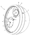
前述したように、本発明は、ジンバルサスペンションを用いて支持体30に傾斜可能に取り付けられた時計10を備える海洋クロノメータに関する。図示した例では、時計10は、球体の一部の形態であるケース11を備え、このケースの内部には時計の時計ムーブメントMが収容され、このムーブメントの駆動手段は香箱Bで形成される。ケース11は、ガラスカバーによって従来の防水性を保つ方法で閉じられ、ガラスカバーの下には、図1aに見られるように、文字盤C、針A、および時計ムーブメントが配置されている。時計10のジンバルサスペンションは、それ自体が公知のもので、単純にサスペンションリング12で表示されている。リング12と支持体30との間の機械的な接続は、図を明瞭にする目的で図示していない。
As described above, the present invention relates to an ocean chronometer including the
本発明によるクロノメータは、支持体が受け台20も備え、受け台が、時計がジンバルサスペンション上で自由に動く休止位置(図1)と、時計が受け台に載っている保持位置(図2a、図3)との間を並進運動することを特徴とする。また、図示した例では、受け台は、休止位置と保持位置との間の中間位置も有し、中間位置では、受け台の磁気手段は、時計の対応する磁気手段と協働して時計を受け台内で方向付けるように適応している。受け台は、この場合、支持体に実質的に垂直な方向に並進運動する。
In the chronometer according to the invention, the support also comprises a
受け台の可動性を確実にするために、支持体は、図示した例では、
受け台の両側に位置している2つの保持軸31であって、この両軸に受け台が孔のあいた固定突起部31aを介して摺動可能に取り付けられ、孔の直径が保持軸31の直径に合っている、2つの保持軸と、
受け台を保持軸に沿って保持位置と休止位置との間で摺動させるハサミ型持ち上げ機構32(図5)であって、このように、レバー33を介して使用者によって手動で動きを設定される、ハサミ型持ち上げ機構と
を備えている。
In order to ensure the mobility of the cradle, the support is, in the illustrated example,
The two holding
The scissor-type lifting mechanism 32 (FIG. 5) that slides the cradle between the holding position and the rest position along the holding shaft, and thus the movement is manually set by the user via the
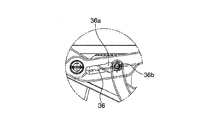
さらに詳細には、図示した例では、持ち上げ機構は、レバー33およびハサミ構成に関わる2対の接続ロッド34、35(特に図1、図2a、図2cを参照)を備え、接続ロッドの各対は、後述するように保持軸31に連結されている。1対の接続ロッドは、以下のように形成された2つの接続ロッド34、35を備えている。1つの接続ロッド34は、支持体30に対するピボットリンクによって関節連結した足部を備え、接続ロッド34の自由端は、受け台の固定突起部31aに機械的に関節連結されている。また、接続ロッド34は弾性ストリップ34bを備え、これによって固定子突起部31aをクランプでき、ケースが的確にロックされるようにすることにも注意されたい。1つの接続ロッド35は、支持体30に対するピボットリンクによって関節連結した足部を備え、接続ロッド35の自由端は、接続ロッド35の長手軸に沿って広がっている長円形開口36を有する。2つの接続ロッド34、35は、ピボット接続によって互いにつながり、ピボット接続部は、接続ロッド34の2つの端部の間、および接続ロッド35の足部と長円形開口36との間を通るピン35aを有してハサミの作用を達成する。2つの接続ロッド35の自由端は、一方の接続ロッド35が動くと、機械的にもう一方の接続ロッド35が同じ動きをするように互いにしっかりと接続されている。レバー33は、実質的にL字型または「1」の形状をした2つの側を有する。レバーの大きい側の自由端はハンドル37を形成する。レバーの小さい側38の自由端は、接続ロッド35の長円形開口36の中に摺動可能に取り付けられる。長円形開口にある2つのノッチ36a、36bは、レバーの小さい側の自由端を所定位置で不動にできる。最後に、レバー33の小さい側と大きい側との間の交差部は、ピボットリンクによって支持体30に関節連結される。休止時、接続ロッド34、35の対は閉じたハサミを形成し、レバーの小さい側38の自由端は、ハサミ軸35aの側にある長円形開口の中に位置している。レバーハンドル37を引く/回転させると、長円形開口36の中にあるレバーの小さい側38の自由端が接続ロッド35の自由端に向かって移動し、この移動によって今度はハサミ軸35aが上がり、接続ロッド34の自由端および受け台の固定突起部31aが保持軸31に沿って間接的に上がる。そのため、レバー33を引く/回転させると、受け台20が保持軸に沿って並進運動する。
More particularly, in the illustrated example, the lifting mechanism comprises two pairs of connecting
受け台20は磁気手段22を備え、この磁気手段は、時計の対応する磁気手段14と協働して、受け台が保持位置にあるときに時計を受け台の中で不動にすることができる。図示した例では、受け台は環状であり、その磁気手段は、受け台の内周に沿って分布している。
The
本発明によるクロノメータの1つの実施形態(図示せず)によれば、時計の磁気手段14は、時計ケース11の周囲に沿って、好ましくはシールされたケースの中で、時計のガラスカバーの平面に実質的に平行な平面に分布している複数の磁気装置を備えている。受け台の磁気手段と時計の磁気手段との間の磁気連結により、時計が受け台に載っているときに時計の重量の平衡を保つように時計を受け台に対して方向付けることができる。
According to one embodiment (not shown) of a chronometer according to the invention, the magnetic means 14 of the watch are arranged around the
図示した実施形態によれば、支持体30の受け台20は、時計を不動にすることに加えて、機械式時計ムーブメントの香箱を巻き上げることができる。そのために、時計10は、巻き上げ回転子13を含む機構を備え、磁気手段14は、回転子の外周に沿って分布した複数の磁気装置を備えて、受け台が保持位置または中間位置にあるときに受け台の磁気手段と協働するように適応した時計の磁気手段を形成する。時計ケースの中では、回転子13は歯車13aと結合し、歯車は、公知の方法で香箱巻き上げ列の通常の要素に連結している。
According to the illustrated embodiment, the
受け台20は環状固定子21を備え、環状固定子は、ここでは歯車(図3)の形態で、支持体に対して回転するように取り付けられる。受け台の固定子は、固定子の内周に沿って分布した複数の磁気装置22を備えて受け台の磁気手段を形成する。受け台は、固定子(歯車)の外周を保護するためのケーシング23も備えている。
The
最後に、支持体は、受け台が保持位置にあるときに固定子21と噛み合うように適応した巻き上げピニオン40によって完全となり、巻き上げピニオン40と固定子21との機械的接続が可能になるように、ケーシングには開口24が設けられる。ケースの外部に設けられ時計から独立している巻き上げピニオン40は、キー41、指回し式円形板、ハンドルなどを用いて手動で回転駆動でき、場合によっては電動補助装置で補足されてもよい。巻き上げピニオンと受け台とは共に巻き上げ手段を形成し、巻き上げ手段は、
巻き上げ手段、特に固定子21に時計回転子13が磁気によって連結し、その際に時計ケースも受け台で不動になる、(受け台の保持位置に相当する)巻き上げ位置と、
時計回転子が巻き上げ手段に対して自由に回転する(受け台の休止位置に相当する)休止位置と
の間で可動式である。
Finally, the support is complete by a winding
A winding position (corresponding to a holding position of the cradle), in which the
The timepiece rotor is movable with respect to a rest position (corresponding to a rest position of the cradle) that freely rotates with respect to the winding means.
「磁気装置」とは、本明細書を通して、永久または非永久の磁石、または磁気によって磁石に連結できる磁気部分という意味である。例えば、受け台の磁気装置22を作製するために磁石を使用でき、時計の磁気装置14を作製するために磁気部分を使用する、またはこの逆も同様であり、あるいは受け台の磁気装置および時計の磁気装置を作製するために磁石を選択する。磁気装置の選択、その寸法、磁力、数、ならびに受け台の周囲への配置および時計の周囲への配置は、時計を受け台で不動にし、かつ/または巻き上げ回転子13を回転させるのに必要な磁力に応じて決定する。
By “magnetic device” is meant throughout this specification a permanent or non-permanent magnet, or a magnetic part that can be magnetically coupled to a magnet. For example, magnets can be used to make the cradle
図示した実施形態による受け台は、以下の方法で使用される。休止位置では(図5b、図5c)、受け台は支持体に載っていて時計から離れている。受け台の磁気手段22および時計の磁気手段14は互いに離れているため、両者の間には磁気連結がない。そのため、時計はジンバルサスペンション上で自由に動く。 The cradle according to the illustrated embodiment is used in the following manner. In the rest position (FIGS. 5b, 5c), the cradle rests on the support and is away from the watch. Since the magnetic means 22 of the cradle and the magnetic means 14 of the timepiece are separated from each other, there is no magnetic connection between them. Therefore, the watch moves freely on the gimbal suspension.
使用者がレバー33のハンドル37を引くと、受け台は機構32によって(ノッチ36aに相当する)中間位置まで持ち上げられる。受け台20は、時計ケース11に近くなるが接触せず、受け台の磁気手段22は時計の磁気手段14に磁気連結される(図5d)。このように、時計はジンバルサスペンションに可動式に取り付けられるため、固定子の磁気装置22は、受け台の固定子の軸と時計の回転子の軸とが同列になるまで時計の磁気装置14を引きつける。この位置になると、時計は、磁気連結によって受け台の上で静止状態かつ(重量の観点での)平衡状態に保持される。
When the user pulls the
使用者がレバー33をもう少し下げると、受け台は機構32によって保持位置(ノッチ36b)まで持ち上げられる。受け台は時計ケース11と接触状態になるため、ストリップ34bが固定子をケース11に押しつけるのを補助して時計の重量が受け台にかかる。そのとき、受け台の磁気装置22と時計の磁気手段14との間の磁気連結は最大である。時計は受け台上で不動になるため、ジンバルサスペンションは時計の重量から解放される。この位置でも、巻き上げピニオン40は受け台の固定子21と噛み合う。そのため、キー41が回転すると巻き上げピニオンが回転させられ、巻き上げピニオンが今度は固定子21を回転させる。次に、固定子は、磁気連結によって回転子13を回転させ、この磁気連結が時計の香箱を巻き上げる。
When the user lowers the lever 33 a little, the cradle is lifted by the
本発明によるクロノメータは、磁気絶縁手段50によって有利に完全となり、磁気絶縁手段は、
受け台が休止位置にあり、絶縁手段が受け台の磁気手段と時計の磁気手段との間に磁気遮蔽面を形成する、絶縁位置と、
受け台が保持位置にあるときに磁気絶縁手段が作動しない、後退位置と
の間で可動式である。
The chronometer according to the invention is advantageously perfected by the magnetic insulation means 50, the magnetic insulation means being
An insulating position in which the cradle is in a rest position and the insulating means forms a magnetic shielding surface between the magnetic means of the cradle and the magnetic means of the watch;
The magnetic insulation means does not operate when the cradle is in the holding position, and is movable between the retracted position.
図示した例では、磁気絶縁手段は、磁気遮蔽材料で作製された複数のブレード51で形成されている。ブレードは、受け台の内側で実質的に円上に並んで取り付けられている。ブレードはそれぞれが、
ブレードが受け台の磁気装置22を覆うように展開され、それによって固定子と回転子との間の残りの磁気連結がいずれも中立になる、受け台20の休止位置に相当する絶縁位置と、
ブレードが受け台から離れるように動き、回転子の磁気装置と固定子の磁気装置との間に磁気遮蔽面を形成しなくなる、受け台の保持位置に相当する後退位置と
の間で、支持体に実質的に平行な回動軸に対して回動するように取り付けられる。
In the illustrated example, the magnetic insulation means is formed of a plurality of
An insulating position corresponding to the rest position of the
The blade moves away from the cradle and does not form a magnetic shielding surface between the magnetic device of the rotor and the magnetic device of the stator. It is attached so as to rotate with respect to a rotation axis substantially parallel to the rotation axis.
実際にここでは、ブレードは、受け台のケーシング23に載っており、受け台20が並進運動したときに回転させられる。受け台20が動いている間、ブレードをハウジング23に対して保持するために各ブレードに釣合い重り52を設けてもよい。
In fact, here, the blade rests on the
直前に記載した例では、機構は、固定子を上げ下げする動きを達成するハサミ型のものだが、変形例ではその他の種類の持ち上げ機構を検討してもよいことは明らかであり、例として、単純な膝レバー機構もしくは接続ロッドが2つある機構、または膝レバープレス機構、もしくは例えば伸縮式のスクリュージャッキがあるものまたはないものであるジャックシステムなどがある。このような機構は、特に、Decoopman発行の「Des Mecanismes Elementaires」と題する著作、ISBN97823650027の第144頁および第145頁に記載されており、本文献を参照により本願に組み入れる。 In the example just described, the mechanism is of the scissors type that achieves the movement of raising and lowering the stator, but it is clear that other types of lifting mechanisms may be considered in the variant, A knee lever mechanism or a mechanism with two connecting rods, a knee lever press mechanism, or a jack system with or without a telescopic screw jack, for example. Such mechanisms are described in particular in the book entitled “Des Machinery Elements Elementaires” published by Decoopman, pages 144 and 145 of ISBN 9783650027, which is incorporated herein by reference.
10 時計
11 ケース
12 サスペンション
13 回転子
14 磁気装置
20 受け台
21 固定子
22 磁気装置
23 ケーシング
24 開口
30 支持体
31 保持軸
31 固定突起部
31 持ち上げ機構
33 レバー
34、35 ハサミを形成する接続ロッドの対
35a 2つの接続ロッド35の間の機械リンク
36 長円形開口
36a、36b 長円形開口内のノッチ
37 レバー33のハンドル
38 レバーの小さい側
39 2つの接続ロッド34、35の接続ピン
40 巻き上げピニオン
41 キー
50 磁気絶縁手段
51 ブレード
52 釣合い重り
DESCRIPTION OF
Claims (13)
前記受け台が前記休止位置にあり、前記絶縁手段が前記受け台の前記磁気手段と前記時計の前記磁気手段との間に磁気遮蔽面を形成する、絶縁位置と、
前記受け台が前記保持位置にあるときに前記磁気絶縁手段が作動しない、後退位置と
の間で可動式である、請求項3または請求項4に記載の海洋クロノメータ。 Magnetic insulation means (50, 51) are also provided,
An insulating position in which the cradle is in the rest position and the insulating means forms a magnetic shielding surface between the magnetic means of the cradle and the magnetic means of the watch;
The marine chronometer according to claim 3 or 4, wherein said magnetic insulation means does not operate when said cradle is in said holding position and is movable between retracted positions.
前記受け台を摺動可能に取り付ける少なくとも1つの保持軸(31)と、
前記受け台を前記保持位置と前記休止位置との間で前記保持軸に沿って摺動させるためのハサミ型持ち上げ機構(32)と
を備える、請求項1から請求項9のいずれかに記載の海洋クロノメータ。 The support is
At least one holding shaft (31) for slidably attaching the cradle;
The scissor-type lifting mechanism (32) for sliding the cradle along the holding shaft between the holding position and the rest position, according to any one of claims 1 to 9. Marine chronometer.
前記時計の前記巻き上げ回転子(13)が前記巻き上げ手段に磁気連結する巻き上げ位置と、
前記時計の前記巻き上げ回転子(13)が前記巻き上げ手段に対して自由に回転する休止位置と
の間で可動式であることと
を特徴とする、海洋クロノメータ。 A marine chronometer comprising a timepiece (10) tiltably attached to a support using a gimbal suspension, the timepiece comprising a winding rotor (13) driven by a barrel and meshed with a barrel winding row. Comprising a mechanical movement; and the support comprises a winding means, the winding means,
A winding position at which the winding rotor (13) of the timepiece is magnetically coupled to the winding means;
Marine chronometer, characterized in that the winding rotator (13) of the timepiece is movable between a rest position in which it rotates freely with respect to the winding means.
Applications Claiming Priority (2)
| Application Number | Priority Date | Filing Date | Title |
|---|---|---|---|
| EP16196926.6 | 2016-11-02 | ||
| EP16196926.6A EP3318933B1 (en) | 2016-11-02 | 2016-11-02 | Device for immobilising and/or winding a marine chronometer |
Publications (2)
| Publication Number | Publication Date |
|---|---|
| JP2018072338A JP2018072338A (en) | 2018-05-10 |
| JP6483217B2 true JP6483217B2 (en) | 2019-03-13 |
Family
ID=57223575
Family Applications (1)
| Application Number | Title | Priority Date | Filing Date |
|---|---|---|---|
| JP2017204997A Active JP6483217B2 (en) | 2016-11-02 | 2017-10-24 | A device that immobilizes and / or rolls up a marine chronometer |
Country Status (6)
| Country | Link |
|---|---|
| US (1) | US10401797B2 (en) |
| EP (1) | EP3318933B1 (en) |
| JP (1) | JP6483217B2 (en) |
| CN (1) | CN108021016B (en) |
| CH (1) | CH713106A2 (en) |
| HK (1) | HK1253935A1 (en) |
Families Citing this family (2)
| Publication number | Priority date | Publication date | Assignee | Title |
|---|---|---|---|---|
| CH714171B1 (en) * | 2017-09-22 | 2019-08-30 | Montres Breguet Sa | Device for raising and / or immobilizing a marine chronometer. |
| USD881058S1 (en) * | 2018-03-05 | 2020-04-14 | Montres Breguet S.A. | Escapement wheel |
Family Cites Families (16)
| Publication number | Priority date | Publication date | Assignee | Title |
|---|---|---|---|---|
| US227972A (en) * | 1880-05-25 | oafieis | ||
| CH2960A (en) * | 1890-12-20 | 1891-04-30 | Nardin Paul D | Improvement in the construction of marine chronometers |
| US2425602A (en) * | 1945-01-13 | 1947-08-12 | Hamilton Watch Co | Cantilever support for gimbal carried instruments |
| US3191901A (en) * | 1962-11-05 | 1965-06-29 | James W Green | Ornamental watch, portrait and plaque stand |
| DE2929372C2 (en) * | 1979-07-20 | 1982-06-09 | Vdo Adolf Schindling Ag, 6000 Frankfurt | Case for a clock with a holder |
| USD388001S (en) * | 1995-02-20 | 1997-12-23 | Severin Montres AG (Severin Montres SA) (Severin Montres Ltd) | Watch |
| DE60123403T2 (en) * | 2000-08-11 | 2007-08-23 | Seiko Epson Corp. | ELECTRONIC DEVICE AND METHOD FOR CONTROLLING THEREOF |
| CH700972A2 (en) * | 2009-05-06 | 2010-11-15 | Emilia Lacote | Watch mobile movement. |
| CH705244B1 (en) * | 2011-07-07 | 2016-06-30 | Gfpi S A | Timepiece. |
| EP2560054B1 (en) * | 2011-08-17 | 2017-11-15 | ETA SA Manufacture Horlogère Suisse | Winding of a clock mechanism by pressing or pulling |
| CH706352B1 (en) * | 2012-04-13 | 2016-11-30 | Montres Breguet Sa | Timepiece including a winding mechanism with contactless torque transfer. |
| WO2014166719A2 (en) * | 2013-04-10 | 2014-10-16 | The Swatch Group Research And Development Ltd | Device for winding up a watch with self-winding mechanism |
| EP2787400B1 (en) * | 2013-04-03 | 2016-08-03 | Chopard Technologies SA | Clockwork with tourbillon and balance stop mechanism |
| EP2990885B1 (en) * | 2013-12-23 | 2017-07-26 | ETA SA Manufacture Horlogère Suisse | Mechanical clock movement with magnetic escapement |
| JP6547379B2 (en) * | 2015-04-10 | 2019-07-24 | セイコーエプソン株式会社 | Communication system, electronic watch and communication device |
| US10324487B2 (en) * | 2016-10-27 | 2019-06-18 | Fluidity Technologies, Inc. | Multi-axis gimbal mounting for controller providing tactile feedback for the null command |
-
2016
- 2016-11-02 EP EP16196926.6A patent/EP3318933B1/en active Active
- 2016-11-02 CH CH01463/16A patent/CH713106A2/en not_active Application Discontinuation
-
2017
- 2017-10-12 US US15/730,900 patent/US10401797B2/en active Active
- 2017-10-24 JP JP2017204997A patent/JP6483217B2/en active Active
- 2017-11-01 CN CN201711057817.2A patent/CN108021016B/en active Active
-
2018
- 2018-10-12 HK HK18113084.0A patent/HK1253935A1/en unknown
Also Published As
| Publication number | Publication date |
|---|---|
| CN108021016B (en) | 2021-01-01 |
| EP3318933B1 (en) | 2020-03-25 |
| CN108021016A (en) | 2018-05-11 |
| JP2018072338A (en) | 2018-05-10 |
| US10401797B2 (en) | 2019-09-03 |
| US20180120772A1 (en) | 2018-05-03 |
| EP3318933A1 (en) | 2018-05-09 |
| HK1253935A1 (en) | 2019-07-05 |
| CH713106A2 (en) | 2018-05-15 |
Similar Documents
| Publication | Publication Date | Title |
|---|---|---|
| JP6483217B2 (en) | A device that immobilizes and / or rolls up a marine chronometer | |
| JP5046326B2 (en) | A watch having a striking bell mechanism having a single barrel | |
| JP5436788B2 (en) | A watch having a power reserve display mechanism | |
| ES2593815T3 (en) | Watch movement with whirlwind and steering wheel stop mechanism | |
| JP6226988B2 (en) | Balance stop device for a watch with a tourbillon | |
| JP5030091B2 (en) | Clock with improved time setting device | |
| JP5467056B2 (en) | Watch with chronograph mechanism | |
| JP3145532U (en) | Aperture device | |
| KR20070093044A (en) | Watch control device | |
| CN109541923B (en) | Device for rewinding and/or immobilizing a nautical timepiece | |
| JP5945830B2 (en) | Watch power reserve indicator | |
| JP6960027B2 (en) | Self-winding mobile watch | |
| BRPI0704311B1 (en) | ACTUATOR WITH ROTARY CONTROL PANEL | |
| JP2018096813A (en) | Watch movement, mechanical type watch and claw lever engagement release method | |
| JP2017203686A (en) | Automaton clock | |
| RU2633798C1 (en) | Antenna deployment mechanism | |
| JP2004354366A5 (en) | ||
| WO2014069335A1 (en) | Focal-plane shutter and optical device | |
| JP5355073B2 (en) | Lens barrier device | |
| CN108400675A (en) | It is a kind of that there is unidirectional and Bidirectional locking handoff functionality motor | |
| CN212181265U (en) | Navigation timer | |
| JP5185667B2 (en) | Blade drive device | |
| KR20150125395A (en) | Focusing device for projector | |
| US10990065B2 (en) | Mechanical clock | |
| CH174388A (en) | Time indication device by light projection. |
Legal Events
| Date | Code | Title | Description |
|---|---|---|---|
| A977 | Report on retrieval |
Free format text: JAPANESE INTERMEDIATE CODE: A971007 Effective date: 20180815 |
|
| A131 | Notification of reasons for refusal |
Free format text: JAPANESE INTERMEDIATE CODE: A131 Effective date: 20180911 |
|
| TRDD | Decision of grant or rejection written | ||
| A01 | Written decision to grant a patent or to grant a registration (utility model) |
Free format text: JAPANESE INTERMEDIATE CODE: A01 Effective date: 20190205 |
|
| A61 | First payment of annual fees (during grant procedure) |
Free format text: JAPANESE INTERMEDIATE CODE: A61 Effective date: 20190213 |
|
| R150 | Certificate of patent or registration of utility model |
Ref document number: 6483217 Country of ref document: JP Free format text: JAPANESE INTERMEDIATE CODE: R150 |
|
| R250 | Receipt of annual fees |
Free format text: JAPANESE INTERMEDIATE CODE: R250 |
|
| R250 | Receipt of annual fees |
Free format text: JAPANESE INTERMEDIATE CODE: R250 |
|
| R250 | Receipt of annual fees |
Free format text: JAPANESE INTERMEDIATE CODE: R250 |