JP6482482B2 - RJ45 plug latch guard with integrated release tab - Google Patents
RJ45 plug latch guard with integrated release tab Download PDFInfo
- Publication number
- JP6482482B2 JP6482482B2 JP2016006888A JP2016006888A JP6482482B2 JP 6482482 B2 JP6482482 B2 JP 6482482B2 JP 2016006888 A JP2016006888 A JP 2016006888A JP 2016006888 A JP2016006888 A JP 2016006888A JP 6482482 B2 JP6482482 B2 JP 6482482B2
- Authority
- JP
- Japan
- Prior art keywords
- plug
- communication
- latch
- latch guard
- guard
- Prior art date
- Legal status (The legal status is an assumption and is not a legal conclusion. Google has not performed a legal analysis and makes no representation as to the accuracy of the status listed.)
- Expired - Fee Related
Links
- 238000004891 communication Methods 0.000 claims description 83
- 238000000034 method Methods 0.000 description 19
- 241000251468 Actinopterygii Species 0.000 description 6
- 238000007726 management method Methods 0.000 description 6
- 101100219344 Arabidopsis thaliana CAT7 gene Proteins 0.000 description 1
- 101150013917 CAT8 gene Proteins 0.000 description 1
- 238000010276 construction Methods 0.000 description 1
- 230000000881 depressing effect Effects 0.000 description 1
- 238000009429 electrical wiring Methods 0.000 description 1
- 239000003365 glass fiber Substances 0.000 description 1
- 230000003993 interaction Effects 0.000 description 1
- 238000012986 modification Methods 0.000 description 1
- 230000004048 modification Effects 0.000 description 1
- 230000002093 peripheral effect Effects 0.000 description 1
Images


Classifications
-
- H—ELECTRICITY
- H01—ELECTRIC ELEMENTS
- H01R—ELECTRICALLY-CONDUCTIVE CONNECTIONS; STRUCTURAL ASSOCIATIONS OF A PLURALITY OF MUTUALLY-INSULATED ELECTRICAL CONNECTING ELEMENTS; COUPLING DEVICES; CURRENT COLLECTORS
- H01R13/00—Details of coupling devices of the kinds covered by groups H01R12/70 or H01R24/00 - H01R33/00
- H01R13/62—Means for facilitating engagement or disengagement of coupling parts or for holding them in engagement
- H01R13/627—Snap or like fastening
- H01R13/6275—Latching arms not integral with the housing
-
- F—MECHANICAL ENGINEERING; LIGHTING; HEATING; WEAPONS; BLASTING
- F16—ENGINEERING ELEMENTS AND UNITS; GENERAL MEASURES FOR PRODUCING AND MAINTAINING EFFECTIVE FUNCTIONING OF MACHINES OR INSTALLATIONS; THERMAL INSULATION IN GENERAL
- F16B—DEVICES FOR FASTENING OR SECURING CONSTRUCTIONAL ELEMENTS OR MACHINE PARTS TOGETHER, e.g. NAILS, BOLTS, CIRCLIPS, CLAMPS, CLIPS OR WEDGES; JOINTS OR JOINTING
- F16B2/00—Friction-grip releasable fastenings
- F16B2/20—Clips, i.e. with gripping action effected solely by the inherent resistance to deformation of the material of the fastening
- F16B2/22—Clips, i.e. with gripping action effected solely by the inherent resistance to deformation of the material of the fastening of resilient material, e.g. rubbery material
-
- H—ELECTRICITY
- H01—ELECTRIC ELEMENTS
- H01R—ELECTRICALLY-CONDUCTIVE CONNECTIONS; STRUCTURAL ASSOCIATIONS OF A PLURALITY OF MUTUALLY-INSULATED ELECTRICAL CONNECTING ELEMENTS; COUPLING DEVICES; CURRENT COLLECTORS
- H01R13/00—Details of coupling devices of the kinds covered by groups H01R12/70 or H01R24/00 - H01R33/00
- H01R13/62—Means for facilitating engagement or disengagement of coupling parts or for holding them in engagement
- H01R13/627—Snap or like fastening
- H01R13/6271—Latching means integral with the housing
- H01R13/6272—Latching means integral with the housing comprising a single latching arm
-
- H—ELECTRICITY
- H01—ELECTRIC ELEMENTS
- H01R—ELECTRICALLY-CONDUCTIVE CONNECTIONS; STRUCTURAL ASSOCIATIONS OF A PLURALITY OF MUTUALLY-INSULATED ELECTRICAL CONNECTING ELEMENTS; COUPLING DEVICES; CURRENT COLLECTORS
- H01R13/00—Details of coupling devices of the kinds covered by groups H01R12/70 or H01R24/00 - H01R33/00
- H01R13/62—Means for facilitating engagement or disengagement of coupling parts or for holding them in engagement
- H01R13/629—Additional means for facilitating engagement or disengagement of coupling parts, e.g. aligning or guiding means, levers, gas pressure electrical locking indicators, manufacturing tolerances
- H01R13/633—Additional means for facilitating engagement or disengagement of coupling parts, e.g. aligning or guiding means, levers, gas pressure electrical locking indicators, manufacturing tolerances for disengagement only
- H01R13/6335—Additional means for facilitating engagement or disengagement of coupling parts, e.g. aligning or guiding means, levers, gas pressure electrical locking indicators, manufacturing tolerances for disengagement only comprising a handle
-
- H—ELECTRICITY
- H01—ELECTRIC ELEMENTS
- H01R—ELECTRICALLY-CONDUCTIVE CONNECTIONS; STRUCTURAL ASSOCIATIONS OF A PLURALITY OF MUTUALLY-INSULATED ELECTRICAL CONNECTING ELEMENTS; COUPLING DEVICES; CURRENT COLLECTORS
- H01R24/00—Two-part coupling devices, or either of their cooperating parts, characterised by their overall structure
- H01R24/60—Contacts spaced along planar side wall transverse to longitudinal axis of engagement
- H01R24/62—Sliding engagements with one side only, e.g. modular jack coupling devices
- H01R24/64—Sliding engagements with one side only, e.g. modular jack coupling devices for high frequency, e.g. RJ 45
-
- H—ELECTRICITY
- H01—ELECTRIC ELEMENTS
- H01R—ELECTRICALLY-CONDUCTIVE CONNECTIONS; STRUCTURAL ASSOCIATIONS OF A PLURALITY OF MUTUALLY-INSULATED ELECTRICAL CONNECTING ELEMENTS; COUPLING DEVICES; CURRENT COLLECTORS
- H01R43/00—Apparatus or processes specially adapted for manufacturing, assembling, maintaining, or repairing of line connectors or current collectors or for joining electric conductors
- H01R43/16—Apparatus or processes specially adapted for manufacturing, assembling, maintaining, or repairing of line connectors or current collectors or for joining electric conductors for manufacturing contact members, e.g. by punching and by bending
-
- H—ELECTRICITY
- H01—ELECTRIC ELEMENTS
- H01R—ELECTRICALLY-CONDUCTIVE CONNECTIONS; STRUCTURAL ASSOCIATIONS OF A PLURALITY OF MUTUALLY-INSULATED ELECTRICAL CONNECTING ELEMENTS; COUPLING DEVICES; CURRENT COLLECTORS
- H01R2107/00—Four or more poles
Description
現在の電気通信市場では、プラグの事故的な取り外しに起因してネットワークの接続性を喪失する可能性がある。事故的な取り外しは、多くの理由で起こり得る。一つのそのような理由に、データセンタ内の高密度が原因となりRJ45プラグにおけるラッチが互いに非常に近接し、時々この状況では一つのコードを取り外している間に、隣接するコードがぶつかり、または完全に接続が切られることがある。事故的なプラグの取り外しの別の理由には、ヒューマンエラーをもたらすことがある視界の欠如があり、コードが誤ってつかまれた場合に不適切なコードが取り外される。使用用途によっては、労働コストを増すようなミスを回避するために、複数人のオペレータ(プラグを抜くのに一人、正しいプラグかを確認するのに別の一人)が必要になる。 In the current telecommunications market, network connectivity can be lost due to accidental plug removal. Accidental removal can occur for a number of reasons. One such reason is due to the high density in the data center, the latches in the RJ45 plugs are very close to each other, and sometimes in this situation, while removing one cord, adjacent cords collide or are completely May be disconnected. Another reason for accidental plug removal is the lack of visibility that can lead to human error, and improper cords are removed if the cords are mishandled. Depending on the intended use, multiple operators (one person to unplug, one person to confirm correct plug) are required to avoid mistakes that increase labor costs.
通信市場では、電気配線を保護及び収容するために、配電管または他のケーブル管理機器を使用することができる。配線管の中を通して配線を引くために使用できるさまざまな方法がある。配線管の中を通してケーブルを引くためのある共通の方法に、ガラス繊維のフィッシュテープを利用する方法がある。この方法では、フィッシュテープが第一に配線管を通して提供され、そして電気テープを利用してケーブルの一端に付けられ、次に、ケーブルを配線管を通して引き込む。フィッシュテープがケーブルに固定されているときには、それはケーブルの丸い表面上にテープされており、潜在的に滑る性質を有する。このことは、送り込みプロセス全体を最初からやり直す必要があるという結果を生じることがある。 In the communications market, distribution pipes or other cable management equipment can be used to protect and accommodate electrical wiring. There are various methods that can be used to draw wiring through the conduit. One common method for drawing cables through the conduit is to use glass fiber fish tape. In this method, fish tape is first provided through the conduit and applied to one end of the cable using electrical tape, and then the cable is drawn through the conduit. When the fish tape is secured to the cable, it is taped onto the round surface of the cable and has the potential to slide. This can result in the entire delivery process having to be restarted from the beginning.
取り付け及び取り外しが容易、かつ工具を必要としないRJ45コードの事故的な解放を防ぐデバイスが必要とされている。 What is needed is a device that is easy to install and remove and that prevents accidental release of the RJ45 cord without the need for tools.
一実施形態では、本発明は、ラッチを有する通信プラグ用のラッチガードを含み、このラッチガードは、通信プラグをグリップするように構成されたプラグ端、及びプラグ端から延伸するプルタブを含む。プルタブは、プラグ端に接続されたアーム、さらに、プラグ端に対向するアームに接続されたループを含むことができる。ラッチガードのプラグ端は、ラッチガードが通信プラグに取り付けられているときに、通信プラグのラッチを少なくとも部分的にカバーするように構成されたフードを含むことができる。ラッチガードのプラグ端は、少なくとも三つの側面を有することができ、通信プラグは、少なくとも一つの凹部を持つハウジングを有することができる。この場合、ラッチガードのプラグ端の側面のうちの少なくとも一つは、プラグハウジングの少なくとも一つの凹部に係合するためのタブを含むことができる。通信プラグハウジングの少なくとも一つの凹部は、圧着ウィンドウであってもよい。一実施形態では、通信プラグは、RJ45プラグである。 In one embodiment, the present invention includes a latch guard for a communication plug having a latch, the latch guard including a plug end configured to grip the communication plug and a pull tab extending from the plug end. The pull tab can include an arm connected to the plug end and a loop connected to an arm opposite the plug end. The plug end of the latch guard can include a hood configured to at least partially cover the communication plug latch when the latch guard is attached to the communication plug. The plug end of the latch guard can have at least three sides and the communication plug can have a housing with at least one recess. In this case, at least one of the side surfaces of the plug end of the latch guard may include a tab for engaging at least one recess in the plug housing. The at least one recess of the communication plug housing may be a crimp window. In one embodiment, the communication plug is an RJ45 plug.
別の実施形態では、本発明は、通信ケーブル及び通信ケーブルに接続された通信プラグを持つ通信コードを含む。この通信プラグは、ラッチを含む。ラッチガードが、通信プラグに接続することができ、通信プラグをグリップするように構成されたプラグ端、及びプラグ端から延伸するプルタブを有する。プルタブは、プラグ端に接続されたアーム、さらに、プラグ端に対向するアームに接続されたループを含むことができる。ラッチガードのプラグ端は、ラッチガードが通信プラグに取り付けられているときに、通信プラグのラッチを少なくとも部分的にカバーするように構成されたフードを含むことができる。ラッチガードのプラグ端は、少なくとも三つの側面を有することができ、通信プラグは、少なくとも一つの凹部を持つハウジングを有することができる。ラッチガードのプラグ端の側面のうちの少なくとも一つは、プラグハウジングの少なくとも一つの凹部に係合するためのタブを含むことができる。通信プラグハウジングの少なくとも一つの凹部は、圧着ウィンドウであってもよい。一実施形態では、通信プラグは、RJ45プラグである。 In another embodiment, the present invention includes a communication cord having a communication cable and a communication plug connected to the communication cable. The communication plug includes a latch. The latch guard can be connected to the communication plug and has a plug end configured to grip the communication plug and a pull tab extending from the plug end. The pull tab can include an arm connected to the plug end and a loop connected to an arm opposite the plug end. The plug end of the latch guard can include a hood configured to at least partially cover the communication plug latch when the latch guard is attached to the communication plug. The plug end of the latch guard can have at least three sides and the communication plug can have a housing with at least one recess. At least one of the side surfaces of the plug end of the latch guard may include a tab for engaging at least one recess in the plug housing. The at least one recess of the communication plug housing may be a crimp window. In one embodiment, the communication plug is an RJ45 plug.
別の実施形態では、本発明は、通信ジャックにおける通信プラグの取り付け及び取り外し方法を含む。この方法は、ラッチガードを通信プラグに設置するステップと、通信プラグを通信ジャック内に挿入するステップと、ラッチガードのタブのプルタブを引いてラッチガードを解放するステップと、通信プラグのラッチを押し下げるステップと、通信プラグを通信ジャックから取り外すステップと、を含む。 In another embodiment, the present invention includes a method for installing and removing a communication plug in a communication jack. The method includes the steps of installing a latch guard on the communication plug, inserting the communication plug into the communication jack, pulling the pull tab on the latch guard tab to release the latch guard, and depressing the communication plug latch. And removing the communication plug from the communication jack.
別の実施形態では、本発明は、通信コードの通信機器への取り付け方法を含む。この方法は、ラッチガードを通信コードの通信プラグに設置するステップと、ラッチガードを引くことによって、配電管及び配線管のいずれかの中を通して通信コードを引き込むステップと、ラッチガードを通信プラグから取り外すステップと、通信プラグに対するラッチガードの向きを反転するステップと、ラッチガードを通信プラグに再び取り付けるステップと、通信プラグを通信機器の通信ジャック内に挿入するステップと、を含む。 In another embodiment, the present invention includes a method of attaching a communication cord to a communication device. The method includes the steps of installing a latch guard on a communication plug of a communication cord, pulling the communication cord through one of a distribution pipe and a wiring pipe by pulling the latch guard, and removing the latch guard from the communication plug. Reversing the orientation of the latch guard relative to the communication plug, reattaching the latch guard to the communication plug, and inserting the communication plug into the communication jack of the communication device.
図1〜図8は、RJ45プラグの圧着ウィンドウに係合でき、かつ解放タブへの圧力の印加を通じて容易に取り外すことができる、統合解放タブを持つRJ45プラグラッチガードの一実施形態を示す。 1-8 illustrate one embodiment of an RJ45 plug latch guard with an integrated release tab that can engage the crimp window of the RJ45 plug and can be easily removed through application of pressure to the release tab.
図1において本発明は、ラッチガード126が取り付けられたRJ45コード24(例えば、パッチ、ゾーンまたは他のコード)が加えられたスイッチ22を持つ通信システム20を含む。機器22は、図1にはスイッチとして図示されるが、受動機器であってもよいし、能動機器であってもよい。受動機器の実施例は、これらに限定されないが、モジュラーパッチパネル、パンチダウンパッチパネル、ウォールジャックなどであってもよい。能動機器の実施例は、これらに限定されないが、データセンタまたは通信ルームで見ることができるようなイーサネット(登録商標)スイッチ、ルータ、サーバ、物理層管理システム及びパワーオーバーイーサネット機器、そしてセキュリティデバイス(例えば、カメラ及び他のセンサ)及びドアアクセス機器、並びに電話機、コンピュータ、ファクス、プリンタ及びワークステーションエリアで見ることができるような他の周辺機器であってもよい。通信システム20は、キャビネット、ラック、ケーブル管理(例えば、配電管、配線管及び他のケーブル管理装置)及びオーバーヘッドルーティングシステム、並びに他のそのような機器をさらに含むことができる。
In FIG. 1, the present invention includes a
本発明は、さまざまなシールドまたは非シールドの通信ケーブルまたはシステム、CAT5E、CAT6、CAT6A、CAT7、CAT8及び他のツイストペアイーサネットケーブルのいずれか、並びに他のタイプのケーブルに応用かつ/または実施することができる。コード24は、同様の機器22内において直接的に終端処理された他端(図示せず)を有してもよいし、あるいは、RJ45または他のタイプなどのさまざまなプラグまたはジャックモジュール、ジャックモジュールカセット、及び多くの他のコネクタタイプまたはそれらを組み合わせたもので終端処理してもよい。さらに、コード24は、ケーブルの織機または束で処理してもよいし、加えて、予め定められた織機で処理してもよい。コード24は、パッチコード、ゾーンコード、バックボーンケーブル敷設及び水平ケーブル敷設を含むさまざまな構造をしたケーブル敷設応用で使用することができるが、本発明は、そのような用途のみに限定されない。概して、本発明は、軍事、工業、電気通信、コンピュータ、データ通信、海運及び他の用途にも使用することができる。
The present invention may be applied and / or implemented in various shielded or unshielded communication cables or systems, any of CAT5E, CAT6, CAT6A, CAT7, CAT8 and other twisted pair Ethernet cables, and other types of cables. it can. The
図2は、ラッチガード126が取り付けられたRJ45パッチコード24の等角図である。図3は、ラッチガード126がRJ45コード24に取り付けられるときの位置付けでの分解等角図である。図4は、ケーブル軸を中心にして180°回転したラッチガード126の等角図を示す。図4に最もよく示すように、プラグラッチガード126は解放タブ140を含む。解放タブ140の一部分は、RJ45パッチコード24のプラグ25の底面(プラグ25の底面は、ラッチ38と対向する側面である)に係合するように構成される。アーム136が、解放タブ140の前部133の対向する側面から延伸し、プラグ25の対向する側面を包み込む。ラッチガード126におけるアーム136は、ラッチ38の頂点よりも高く延伸し、ラッチ38の押し下げを防ぐ。一実施形態では、アーム136は、ラッチ38の頂点を越えて延伸した後、互いに向かって内側に曲がり、その結果として、プラグ25の上面に接触して付加的な支持を提供することができる。
FIG. 2 is an isometric view of the
図5は、図2の切断線5−5の周囲の断面図である。この図では、タブ132が圧着ウィンドウ34内に挿入されており、このようにしてラッチガード126がRJ45コード24に固定される。ラッチガード126がRJ45パッチコード24に取り付けられ、そしてラッチガード126が取り付けられた隣接するRJ45パッチコード24があると、アーム136が、取り外しを妨害及び阻止するように、ケーブル軸と垂直に外部において屈曲する。
FIG. 5 is a cross-sectional view around the section line 5-5 in FIG. In this figure, a
図6は、解放タブ140の使用を通じてラッチガードがRJ45パッチコード24から取り外された位置付けでの等角図である。ラッチガード126は、プラグラッチ38を解放するために、RJ45パッチコード24から完全には取り外さなくてもよい。
FIG. 6 is an isometric view with the latch guard removed from the
図7は、シングルポート41に焦点を合わせた、通信システム20の正面図である。アーム136における開口142を通じて、ポート41の前面にインジケータまたはLED光43の視界をもたらすことができる。
FIG. 7 is a front view of the
RJ45パッチコード24へのラッチガード126の組み立ての代替的な方法を図8に示す。この図では、パッチコード24が、解放タブ140の後部135における開口144を通して送り込まれる。解放タブ140における開口144は、RJ45パッチコード24が組み立てられた後に、コード24が開口144を通り抜けられるように十分に大きい。このタイプの取り付けの利点は、直径がより小さいケーブル48でも、アーム136間の間隔が、ラッチガード126をパッチコード24から取り除き、それを無くすのに十分な大きさであり、その結果として、図8の方法では、パッチコード24からのガード126の不慮の取り除きが回避されることにある。また、この代替的な方法で組み立てられたラッチガード126は、使用されていないときには圧力をケーブル48に印加し、ケーブルの全長に沿って摺動せず、そして位置を誤ることがない。さらに、この代替的な位置付けでは、解放タブ140間の間隔が増大するために、取り外し中に、解放タブ140の上部と下部とがより容易に区別される。しかしながら、この位置付けは、ラッチガード126のRJ45パッチコード24への組み立てに要する時間を増し、ブラウンフィールドでの用途におけるRJ45パッチコード24では、通信システム20の少なくとも一つの側面においてプラグを抜く必要がある。
An alternative method of assembling the
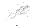
図9〜図15は、RJ45プラグの圧着ウィンドウに係合し、かつ解放タブへの圧力の印加を通じて容易に取り外すことができる、統合解放タブを持つRJ45プラグラッチガードの代替的な実施形態を示す。この実施形態は、インジケータLEDの遮るものがない眺め、並びに図1〜図8の実施形態のものと反対の位置付けの解放タブをもたらすことができる。 FIGS. 9-15 illustrate an alternative embodiment of an RJ45 plug latch guard with an integrated release tab that engages the crimp window of the RJ45 plug and can be easily removed through application of pressure to the release tab. . This embodiment can provide an unobstructed view of the indicator LED, as well as a release tab positioned opposite to that of the embodiment of FIGS.
図9は、RJ45パッチコード24が挿されたスイッチ22を持つシステム21を示し、ラッチガード226が取り付けられた第二の実施形態である。通信システム21は、キャビネット、ラック、ケーブル管理、パッチパネル、オーバーヘッドルーティングシステム、水平ケーブル敷設、及び他のそのような機器をさらに含むことができる。
FIG. 9 shows a
図10は、プラグラッチガード226が取り付けられたRJ45パッチコード24の等角図である。図11は、ラッチガード226がRJ45パッチコード24に取り付けられるときの位置付けでの分解等角図である。これは、図1〜図8のRJ45プラグラッチガードとは異なり、ラッチガード226が、前面ではなく背面に取り付けられている。図12は、ケーブル軸を中心にして180°回転し、垂直軸28を中心にして180°回転したラッチガード226の等角図を示す。図12に最もよく示すように、ラッチガード226は、プラグ25の上面に係合可能な解放タブ240を含む。解放タブ240は、解放タブ236の前部233においてそこにランプ236を成形させる。ラッチガード226におけるランプ236は、RJ45プラグラッチ38の頂点よりも高く延伸し、ラッチ38の押し下げを防ぐ。アーム237が、解放タブ240の前部233の対向する側面から延伸し、プラグ25の側面を囲む。次に、アーム237は、それぞれの端部において互いに向かって内側に曲がる。
FIG. 10 is an isometric view of the
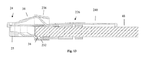
図13は、図10の切断線13−13の周囲の断面図である。一つ以上のアーム237の端部に位置付けられたタブ232が、圧着ウィンドウ34内に挿入されており、このようにしてラッチガード226がRJ45パッチコード24に固定される。ラッチガード226がRJ45パッチコード24に取り付けられ、ラッチガード226が取り付けられた隣接するRJ45パッチコード24があると、アーム237が、取り外しを妨害及び阻止するように、ケーブル軸と垂直に外部において屈曲する。
13 is a cross-sectional view around the section line 13-13 in FIG. A
図14は、シングルポート41に焦点を合わせた、通信システム21の正面図である。ランプ236が、ポート41の前面にインジケータまたはLED光43の視界をもたらすように位置する。解放タブ240が、スイッチ22の外側に向かって接近性を増大するようにスイッチ22において位置する。
FIG. 14 is a front view of the
RJ45パッチコード24へのラッチガード226の組み立ての代替的な方法を図15に示す。この図では、コード24が、解放タブ240の後部235における開口244を通して送り込まれる。解放タブ240における開口244は、RJ45コード24が組み立てられた後に、コード24が開口244を通り抜けられるように十分に大きい。このタイプの取り付けの利点は、直径がより小さいケーブル48でも、アーム237間の間隔が、ラッチガード226をコード24から取り除き、それを無くすのに十分な大きさであり、その結果として、図15の方法では、コード24からのガード226の不慮の取り除きが回避されることにある。また、この代替的な方法で組み立てられたラッチガード226は、使用されていないときには圧力をケーブル48に印加し、ケーブルの全長に沿って摺動せず、そして位置を誤ることがない。しかしながら、この位置付けは、ラッチガード226のRJ45パッチコード24への組み立てに要する時間を増し、ブラウンフィールドでの用途におけるRJ45コード24では、通信システム21の少なくとも一つの側面においてプラグを抜く必要がある。
An alternative method of assembling the
図16〜図25は、RJ45プラグの圧着ウィンドウに係合し、かつ解放タブへの圧力の印加を通じて容易に取り外すことができる、統合解放タブを持つRJ45プラグラッチガードの別の代替的な実施形態を示す。この代替的な実施形態は、引き輪として機能するような追加の機能性をもたらす、ラッチガードにおけるポケットを含む。 FIGS. 16-25 illustrate another alternative embodiment of an RJ45 plug latch guard with an integrated release tab that engages the crimp window of the RJ45 plug and can be easily removed through application of pressure to the release tab. Indicates. This alternative embodiment includes a pocket in the latch guard that provides additional functionality to function as a pull ring.
図16は、RJ45コード24が装着されたスイッチ22を持つシステム320を示し、ラッチガード326が取り付けられた第三の実施形態である。システム320は、キャビネット、ラック、ケーブル管理、パッチパネル、オーバーヘッドルーティングシステム、水平ケーブル敷設、及び他のそのような機器をさらに含むことができる。
FIG. 16 shows a
図17は、ラッチガード326が取り付けられたRJ45コード24の等角図である。図18は、ラッチガード326がRJ45コード24に取り付けられるときの位置付けでの分解等角図である。これは、図1〜図8のRJ45プラグラッチガードとは異なり、ラッチガード326が、前面ではなく背面から取り付けられている。図19は、ケーブル軸を中心にして180°回転し、垂直軸328を中心にして180°回転したラッチガード326の等角図を示す。ラッチガード326におけるランプ336は、RJ45プラグラッチ38の頂点よりも高く延伸し、ラッチ38の押し下げを防ぐ。アーム337が、解放タブ340の前部333の対向する側面から延伸し、プラグ25の側面を囲む。次に、アーム237は、それぞれの端部において互いに向かって内側に曲がる。
FIG. 17 is an isometric view of the
図20は、図17の切断線20−20の周囲の断面図である。タブ332が圧着ウィンドウ334内に挿入されており、このようにしてラッチガード326がRJ45コード24に固定される。ラッチガード326がRJ45コード24に取り付けられ、ラッチガード326が取り付けられた隣接するRJ45コード24があると、アーム337が、取り外しを妨害及び阻止するように、ケーブル軸と垂直に外部において屈曲する。
20 is a cross-sectional view around the section line 20-20 in FIG. A
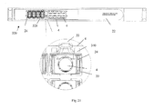
図21は、シングルポート41に焦点を合わせた、通信システム320の正面図である。ランプ336が、ポート41の前面にインジケータまたはLED光43の視界をもたらすように位置する。解放タブ340が、スイッチ22の外側に向かって接近性を増大するようにスイッチ22において位置する。
FIG. 21 is a front view of the
RJ45パッチコード24へのラッチガード326の組み立ての代替的な方法を図22に示す。この図では、コード24が、解放タブ340の後部335における開口344を通して送り込まれる。解放タブ340における開口344は、RJ45コード24が組み立てられた後に、コード24が開口344を通り抜けられるように十分に大きい。このタイプの取り付けの利点は、直径がより小さいケーブル48でも、アーム337間の間隔が、ラッチガード326をコード24から取り除き、それを無くすのに十分な大きさであり、その結果として、図22の方法では、コード24からのガード326の不慮の取り除きが回避されることにある。また、この代替的な組み立てのラッチガード326は、使用されていないときには圧力をケーブル48に印加し、ケーブルの全長に沿って摺動せず、そして位置を誤ることがない。しかしながら、この位置付けは、ラッチガード326のRJ45パッチコード24への組み立てに要する時間を増し、ブラウンフィールドでの用途におけるRJ45コード24では、通信システム320の少なくとも一つの側面においてプラグを抜く必要がある。
An alternative method of assembling the
図23は、ラッチガード326を引き輪として利用できる位置付けにおいてラッチガード326が取り付けられたRJ45コード24の上面等角図である。図24は、ラッチガード326を引き輪として利用できる位置付けにおいてラッチガード326が取り付けられたRJ45コード24の底面等角図である。図25は、図23の切断線25−25の周囲の断面図である。ポケット350が、プラグラッチストップ52を通じてラッチ38を固定し、圧力が印加されたときのラッチガード326の解放を防ぐ。開口344が、引き込み動作中にフィッシュテープを加えることができる包囲特徴として機能し、これによりフィッシュテープをケーブル48の丸い表面に固定するよりもフィッシュテープが滑るリスクがより低くなる。RJ45コード24からラッチガード326を解放するために、プラグが大体RJ45ジャックから解放されるのと同時に、ラッチ38を押し下げる必要がある。ポケット350の係合特徴の二次的な利用として、使用されていない時にパッチコードをフックに掛ける、または店舗での販売中にフックに設置することができる。
FIG. 23 is a top isometric view of the
本発明の特定の実施形態及び用途を図示及び記述したが、本発明が、本明細書に開示した正確な構造及び構成に限定されず、記述したような本発明の精神及び範囲から逸脱することなく、前述から様々な修正、変更及び変化が明らかになり得ることが理解されるはずである。 While particular embodiments and applications of the present invention have been illustrated and described, the present invention is not limited to the precise structure and construction disclosed herein, and departs from the spirit and scope of the invention as described. Rather, it should be understood that various modifications, changes and changes may become apparent from the foregoing.
34,334 圧着ウィンドウ、38 ラッチ、48 ケーブル、126,226,326 ラッチガード、132,232,332 タブ、133,233 前部、136,237,337 アーム、140,240,340 解放タブ、236,336 ランプ 34,334 Crimp window, 38 latch, 48 cable, 126,226,326 latch guard, 132,232,332 tab, 133,233 front, 136,237,337 arm, 140,240,340 release tab, 236 336 lamp
Claims (10)
前記プラグ端から延伸するプルタブと、
を備えた、ラッチを含む通信プラグ用のラッチガードであって、
前記対向するアームが、前記通信プラグの上部に向かって内側に曲がる、ラッチガード。 A plug end configured to grip a communication plug, the plug end having opposing arms extending along opposite sides of the communication plug, the arm being a latch of the communication plug. A plug end extending to a point beyond the apex, and wherein the arm is further configured to leave the latch of the communication plug uncovered ;
A pull tab extending from the plug end;
A latch guard for a communication plug including a latch, comprising :
A latch guard in which the opposing arms bend inward toward the top of the communication plug .
前記通信ケーブルに接続されており、ラッチを含む通信プラグと、
前記通信プラグに接続されたラッチガードであって、前記ラッチガードが、前記通信プラグをグリップするように構成されたプラグ端であって、前記プラグ端が、前記通信プラグの両側に沿って延在する、対向するアームを有し、前記アームが、前記通信プラグのラッチの頂点を越えるポイントまで延在し、前記アームが、前記通信プラグの前記ラッチを覆われていないままにするようにさらに構成されている、プラグ端と、前記プラグ端から延伸するプルタブと、を有し、前記対向するアームが、前記通信プラグの上部に向かって内側に曲がる、ラッチガードと、
を備えている通信コード。 A communication cable;
A communication plug connected to the communication cable and including a latch;
A connected latch guard to the communication plug, before SL latch guard, said communication plug a configured plug end to grip the plug end, extending along both sides of the communication plug Further having an opposing arm, wherein the arm extends to a point beyond the apex of the latch of the communication plug and the arm leaves the latch of the communication plug uncovered. is configured, the plug end, have a, a pull tab extending from the plug end, said opposing arms, song that inwardly toward the top of the communication plug, a latch guard,
Communication code equipped with .
Applications Claiming Priority (2)
| Application Number | Priority Date | Filing Date | Title |
|---|---|---|---|
| US14/599,603 US9450335B2 (en) | 2015-01-19 | 2015-01-19 | RJ45 plug latch guard with integrated release tab |
| US14/599,603 | 2015-01-19 |
Related Child Applications (1)
| Application Number | Title | Priority Date | Filing Date |
|---|---|---|---|
| JP2019022560A Division JP6686193B2 (en) | 2015-01-19 | 2019-02-12 | RJ45 plug latch guard with integrated release tab |
Publications (3)
| Publication Number | Publication Date |
|---|---|
| JP2016134384A JP2016134384A (en) | 2016-07-25 |
| JP2016134384A5 JP2016134384A5 (en) | 2019-01-17 |
| JP6482482B2 true JP6482482B2 (en) | 2019-03-13 |
Family
ID=56408515
Family Applications (2)
| Application Number | Title | Priority Date | Filing Date |
|---|---|---|---|
| JP2016006888A Expired - Fee Related JP6482482B2 (en) | 2015-01-19 | 2016-01-18 | RJ45 plug latch guard with integrated release tab |
| JP2019022560A Expired - Fee Related JP6686193B2 (en) | 2015-01-19 | 2019-02-12 | RJ45 plug latch guard with integrated release tab |
Family Applications After (1)
| Application Number | Title | Priority Date | Filing Date |
|---|---|---|---|
| JP2019022560A Expired - Fee Related JP6686193B2 (en) | 2015-01-19 | 2019-02-12 | RJ45 plug latch guard with integrated release tab |
Country Status (2)
| Country | Link |
|---|---|
| US (1) | US9450335B2 (en) |
| JP (2) | JP6482482B2 (en) |
Families Citing this family (7)
| Publication number | Priority date | Publication date | Assignee | Title |
|---|---|---|---|---|
| US9793664B2 (en) * | 2016-03-11 | 2017-10-17 | Panduit Corp. | Communication connectors |
| CN107575440B (en) * | 2016-07-26 | 2019-04-02 | 六安市恒伟标识有限公司 | The method for realizing quantitative adjustable positioning |
| USD815601S1 (en) * | 2016-12-02 | 2018-04-17 | You Hung International Co., Ltd. | Cable connector |
| USD962169S1 (en) * | 2019-03-29 | 2022-08-30 | Jyh Eng Technology Co., Ltd. | Network cable plug |
| CN112838437B (en) * | 2019-11-22 | 2022-11-15 | 泰连服务有限公司 | Pull strap for plug connector |
| TWI744968B (en) * | 2020-06-24 | 2021-11-01 | 新加坡商鴻運科股份有限公司 | Unlock the stand |
| CN116886600B (en) * | 2023-09-07 | 2023-11-17 | 合肥岭雁科技有限公司 | Anticreep line router |
Family Cites Families (25)
| Publication number | Priority date | Publication date | Assignee | Title |
|---|---|---|---|---|
| US4647726A (en) * | 1985-07-05 | 1987-03-03 | Blum Richard S | Telephone security clamp |
| US4870840A (en) * | 1989-02-06 | 1989-10-03 | Edward Klein | Modular communications jack lock |
| US5462457A (en) * | 1994-09-22 | 1995-10-31 | The Whitaker Corporation | Overmold strain relief and snag prevention feature |
| US5562475A (en) * | 1995-02-02 | 1996-10-08 | Aines Manufacturing Corp. | Modular telephone plug |
| JP3022022U (en) * | 1995-08-25 | 1996-03-12 | 日本製線株式会社 | Protective cover for modular plug |
| US6406325B1 (en) * | 2000-12-28 | 2002-06-18 | Surtec Industries Inc. | Connector plug for network cabling |
| US6579116B2 (en) * | 2001-03-12 | 2003-06-17 | Sentinel Holding, Inc. | High speed modular connector |
| US6409544B1 (en) * | 2001-05-23 | 2002-06-25 | Lorom Industrial Co., Ltd. | Network data transmission cable connector |
| JP3945627B2 (en) * | 2001-12-17 | 2007-07-18 | 株式会社エスケイ工機 | Modular plug cover |
| US6821024B2 (en) * | 2003-04-08 | 2004-11-23 | Itt Manufacturing Enterprises, Inc. | Connector secondary latch |
| US6851957B1 (en) * | 2003-10-16 | 2005-02-08 | International Business Machines Corporation | All-in-one network cable and security cable |
| US7425159B2 (en) * | 2004-05-26 | 2008-09-16 | Commscope, Inc. Of North Carolina | Metallized sled for communication plug |
| DE502005006242D1 (en) * | 2005-08-08 | 2009-01-22 | Reichle & De Massari Fa | FUSE DEVICE FOR A CONNECTOR (PATCH GUARD) |
| JP4439449B2 (en) * | 2005-08-25 | 2010-03-24 | タキゲン製造株式会社 | Plug removal prevention unit and transmission / reception cord |
| JP4723376B2 (en) * | 2005-12-05 | 2011-07-13 | ヘラマンタイトン株式会社 | Communication plug |
| JP4832241B2 (en) * | 2006-09-29 | 2011-12-07 | 矢崎総業株式会社 | Connector protection structure |
| US7806706B2 (en) * | 2007-07-03 | 2010-10-05 | Panduit Corp. | Plug locking assembly and system |
| US7892012B1 (en) * | 2009-08-24 | 2011-02-22 | Archtech Electronics Corporation | Connector locking device |
| CN104682075B (en) * | 2009-10-19 | 2017-09-19 | Adc电信公司 | managed electrical connectivity system |
| US8632352B2 (en) * | 2010-10-07 | 2014-01-21 | Sentinel Connector Systems, Inc. | Method and apparatus for locking a network cable in a jack |
| TWM413736U (en) * | 2011-04-21 | 2011-10-11 | Farng Yiing Entpr Co Ltd | Safety lock assembly of communication wiring |
| CN202121132U (en) * | 2011-05-23 | 2012-01-18 | 富士康(昆山)电脑接插件有限公司 | Cable connector |
| US8348686B1 (en) * | 2011-10-11 | 2013-01-08 | Li-Ping Huang | Plug security structure for electrical connector |
| US8529284B1 (en) * | 2012-04-25 | 2013-09-10 | Quality Computer Accessories Inc. | Connector locking assembly |
| JP3194922U (en) * | 2014-10-03 | 2014-12-18 | 寧波卓新通訊接插件有限公司 | Easy network connector |
-
2015
- 2015-01-19 US US14/599,603 patent/US9450335B2/en not_active Expired - Fee Related
-
2016
- 2016-01-18 JP JP2016006888A patent/JP6482482B2/en not_active Expired - Fee Related
-
2019
- 2019-02-12 JP JP2019022560A patent/JP6686193B2/en not_active Expired - Fee Related
Also Published As
| Publication number | Publication date |
|---|---|
| JP2016134384A (en) | 2016-07-25 |
| US9450335B2 (en) | 2016-09-20 |
| JP2019071298A (en) | 2019-05-09 |
| US20160211610A1 (en) | 2016-07-21 |
| JP6686193B2 (en) | 2020-04-22 |
Similar Documents
| Publication | Publication Date | Title |
|---|---|---|
| JP6686193B2 (en) | RJ45 plug latch guard with integrated release tab | |
| US20160248197A1 (en) | Patch Cord Plug Organizer | |
| US5538438A (en) | RJ connector and cover therefor | |
| US9236683B2 (en) | High bandwidth jack with RJ45 backwards compatibility | |
| US7637773B2 (en) | Patch panel with a variable angle | |
| US9337572B2 (en) | Communication connector with wire containment cap for improved cable retention | |
| JP2023502119A (en) | Field-terminable single-pair Ethernet connector with angled contacts | |
| US20140322966A1 (en) | Ganged housing for coaxial cable connectors | |
| TWI393296B (en) | Security connecting socket and security connecting device | |
| US7241170B1 (en) | Permanent terminations of network cables | |
| US8503851B1 (en) | Cable management system | |
| US20120073857A1 (en) | Cable with integrated cable-management system | |
| CA2788374A1 (en) | Dual latch electrical plug connector for electrical receptacle | |
| CN107743668B (en) | Wire and cable connector | |
| US7910830B2 (en) | Method and apparatus for high-density power distribution unit with integrated cable management | |
| US20150364859A1 (en) | Communication Connector with Wire Containment Cap for Improved Cable Retention | |
| TWM414753U (en) | Optical-fiber communication device | |
| US9972468B2 (en) | Information technology racks having integrated bus plugs and related systems and busways | |
| US9184538B1 (en) | Replacement adaptor for broken clip on cable connector | |
| CN211333191U (en) | Industrial robot base sectional type cable wiring structure | |
| WO2016114703A1 (en) | Back plate | |
| KR20200032533A (en) | Boot member and ethernet connector | |
| CN108604756B (en) | Patch connector and patch cord having the same | |
| US9431770B2 (en) | Shielded communication connectors and systems comprising shielded communication connectors | |
| CN110815176A (en) | Industrial robot base sectional type cable wiring structure |
Legal Events
| Date | Code | Title | Description |
|---|---|---|---|
| A521 | Request for written amendment filed |
Free format text: JAPANESE INTERMEDIATE CODE: A523 Effective date: 20181122 |
|
| A621 | Written request for application examination |
Free format text: JAPANESE INTERMEDIATE CODE: A621 Effective date: 20181122 |
|
| A871 | Explanation of circumstances concerning accelerated examination |
Free format text: JAPANESE INTERMEDIATE CODE: A871 Effective date: 20181122 |
|
| A975 | Report on accelerated examination |
Free format text: JAPANESE INTERMEDIATE CODE: A971005 Effective date: 20181226 |
|
| TRDD | Decision of grant or rejection written | ||
| A01 | Written decision to grant a patent or to grant a registration (utility model) |
Free format text: JAPANESE INTERMEDIATE CODE: A01 Effective date: 20190111 |
|
| A61 | First payment of annual fees (during grant procedure) |
Free format text: JAPANESE INTERMEDIATE CODE: A61 Effective date: 20190212 |
|
| R150 | Certificate of patent or registration of utility model |
Ref document number: 6482482 Country of ref document: JP Free format text: JAPANESE INTERMEDIATE CODE: R150 |
|
| LAPS | Cancellation because of no payment of annual fees |