JP6477453B2 - Object detection device and object detection method - Google Patents
Object detection device and object detection method Download PDFInfo
- Publication number
- JP6477453B2 JP6477453B2 JP2015246691A JP2015246691A JP6477453B2 JP 6477453 B2 JP6477453 B2 JP 6477453B2 JP 2015246691 A JP2015246691 A JP 2015246691A JP 2015246691 A JP2015246691 A JP 2015246691A JP 6477453 B2 JP6477453 B2 JP 6477453B2
- Authority
- JP
- Japan
- Prior art keywords
- upper limit
- speed
- angle
- lateral
- moving
- Prior art date
- Legal status (The legal status is an assumption and is not a legal conclusion. Google has not performed a legal analysis and makes no representation as to the accuracy of the status listed.)
- Active
Links
- 238000001514 detection method Methods 0.000 title claims description 69
- 230000001133 acceleration Effects 0.000 claims description 30
- 238000003384 imaging method Methods 0.000 claims description 22
- 238000005259 measurement Methods 0.000 claims description 13
- 238000013459 approach Methods 0.000 claims description 4
- 230000033001 locomotion Effects 0.000 claims description 3
- 230000004927 fusion Effects 0.000 description 6
- 238000000034 method Methods 0.000 description 6
- 230000008569 process Effects 0.000 description 4
- 230000005540 biological transmission Effects 0.000 description 3
- 230000009471 action Effects 0.000 description 2
- 230000008859 change Effects 0.000 description 2
- 230000007423 decrease Effects 0.000 description 2
- 230000000694 effects Effects 0.000 description 2
- 238000000605 extraction Methods 0.000 description 2
- 238000012986 modification Methods 0.000 description 2
- 230000004048 modification Effects 0.000 description 2
- 238000012545 processing Methods 0.000 description 2
- 238000010586 diagram Methods 0.000 description 1
- 239000000284 extract Substances 0.000 description 1
- 238000012544 monitoring process Methods 0.000 description 1
Images


Classifications
-
- G—PHYSICS
- G08—SIGNALLING
- G08G—TRAFFIC CONTROL SYSTEMS
- G08G1/00—Traffic control systems for road vehicles
- G08G1/16—Anti-collision systems
- G08G1/166—Anti-collision systems for active traffic, e.g. moving vehicles, pedestrians, bikes
-
- B—PERFORMING OPERATIONS; TRANSPORTING
- B60—VEHICLES IN GENERAL
- B60R—VEHICLES, VEHICLE FITTINGS, OR VEHICLE PARTS, NOT OTHERWISE PROVIDED FOR
- B60R21/00—Arrangements or fittings on vehicles for protecting or preventing injuries to occupants or pedestrians in case of accidents or other traffic risks
-
- B—PERFORMING OPERATIONS; TRANSPORTING
- B60—VEHICLES IN GENERAL
- B60T—VEHICLE BRAKE CONTROL SYSTEMS OR PARTS THEREOF; BRAKE CONTROL SYSTEMS OR PARTS THEREOF, IN GENERAL; ARRANGEMENT OF BRAKING ELEMENTS ON VEHICLES IN GENERAL; PORTABLE DEVICES FOR PREVENTING UNWANTED MOVEMENT OF VEHICLES; VEHICLE MODIFICATIONS TO FACILITATE COOLING OF BRAKES
- B60T7/00—Brake-action initiating means
- B60T7/12—Brake-action initiating means for automatic initiation; for initiation not subject to will of driver or passenger
- B60T7/22—Brake-action initiating means for automatic initiation; for initiation not subject to will of driver or passenger initiated by contact of vehicle, e.g. bumper, with an external object, e.g. another vehicle, or by means of contactless obstacle detectors mounted on the vehicle
-
- B—PERFORMING OPERATIONS; TRANSPORTING
- B60—VEHICLES IN GENERAL
- B60W—CONJOINT CONTROL OF VEHICLE SUB-UNITS OF DIFFERENT TYPE OR DIFFERENT FUNCTION; CONTROL SYSTEMS SPECIALLY ADAPTED FOR HYBRID VEHICLES; ROAD VEHICLE DRIVE CONTROL SYSTEMS FOR PURPOSES NOT RELATED TO THE CONTROL OF A PARTICULAR SUB-UNIT
- B60W10/00—Conjoint control of vehicle sub-units of different type or different function
- B60W10/18—Conjoint control of vehicle sub-units of different type or different function including control of braking systems
-
- B—PERFORMING OPERATIONS; TRANSPORTING
- B60—VEHICLES IN GENERAL
- B60W—CONJOINT CONTROL OF VEHICLE SUB-UNITS OF DIFFERENT TYPE OR DIFFERENT FUNCTION; CONTROL SYSTEMS SPECIALLY ADAPTED FOR HYBRID VEHICLES; ROAD VEHICLE DRIVE CONTROL SYSTEMS FOR PURPOSES NOT RELATED TO THE CONTROL OF A PARTICULAR SUB-UNIT
- B60W30/00—Purposes of road vehicle drive control systems not related to the control of a particular sub-unit, e.g. of systems using conjoint control of vehicle sub-units
- B60W30/08—Active safety systems predicting or avoiding probable or impending collision or attempting to minimise its consequences
- B60W30/09—Taking automatic action to avoid collision, e.g. braking and steering
-
- B—PERFORMING OPERATIONS; TRANSPORTING
- B60—VEHICLES IN GENERAL
- B60W—CONJOINT CONTROL OF VEHICLE SUB-UNITS OF DIFFERENT TYPE OR DIFFERENT FUNCTION; CONTROL SYSTEMS SPECIALLY ADAPTED FOR HYBRID VEHICLES; ROAD VEHICLE DRIVE CONTROL SYSTEMS FOR PURPOSES NOT RELATED TO THE CONTROL OF A PARTICULAR SUB-UNIT
- B60W30/00—Purposes of road vehicle drive control systems not related to the control of a particular sub-unit, e.g. of systems using conjoint control of vehicle sub-units
- B60W30/08—Active safety systems predicting or avoiding probable or impending collision or attempting to minimise its consequences
- B60W30/095—Predicting travel path or likelihood of collision
- B60W30/0956—Predicting travel path or likelihood of collision the prediction being responsive to traffic or environmental parameters
-
- B—PERFORMING OPERATIONS; TRANSPORTING
- B60—VEHICLES IN GENERAL
- B60W—CONJOINT CONTROL OF VEHICLE SUB-UNITS OF DIFFERENT TYPE OR DIFFERENT FUNCTION; CONTROL SYSTEMS SPECIALLY ADAPTED FOR HYBRID VEHICLES; ROAD VEHICLE DRIVE CONTROL SYSTEMS FOR PURPOSES NOT RELATED TO THE CONTROL OF A PARTICULAR SUB-UNIT
- B60W40/00—Estimation or calculation of non-directly measurable driving parameters for road vehicle drive control systems not related to the control of a particular sub unit, e.g. by using mathematical models
- B60W40/02—Estimation or calculation of non-directly measurable driving parameters for road vehicle drive control systems not related to the control of a particular sub unit, e.g. by using mathematical models related to ambient conditions
- B60W40/04—Traffic conditions
-
- B—PERFORMING OPERATIONS; TRANSPORTING
- B60—VEHICLES IN GENERAL
- B60W—CONJOINT CONTROL OF VEHICLE SUB-UNITS OF DIFFERENT TYPE OR DIFFERENT FUNCTION; CONTROL SYSTEMS SPECIALLY ADAPTED FOR HYBRID VEHICLES; ROAD VEHICLE DRIVE CONTROL SYSTEMS FOR PURPOSES NOT RELATED TO THE CONTROL OF A PARTICULAR SUB-UNIT
- B60W50/00—Details of control systems for road vehicle drive control not related to the control of a particular sub-unit, e.g. process diagnostic or vehicle driver interfaces
- B60W50/08—Interaction between the driver and the control system
- B60W50/14—Means for informing the driver, warning the driver or prompting a driver intervention
-
- G—PHYSICS
- G01—MEASURING; TESTING
- G01S—RADIO DIRECTION-FINDING; RADIO NAVIGATION; DETERMINING DISTANCE OR VELOCITY BY USE OF RADIO WAVES; LOCATING OR PRESENCE-DETECTING BY USE OF THE REFLECTION OR RERADIATION OF RADIO WAVES; ANALOGOUS ARRANGEMENTS USING OTHER WAVES
- G01S13/00—Systems using the reflection or reradiation of radio waves, e.g. radar systems; Analogous systems using reflection or reradiation of waves whose nature or wavelength is irrelevant or unspecified
- G01S13/02—Systems using reflection of radio waves, e.g. primary radar systems; Analogous systems
- G01S13/50—Systems of measurement based on relative movement of target
- G01S13/58—Velocity or trajectory determination systems; Sense-of-movement determination systems
- G01S13/589—Velocity or trajectory determination systems; Sense-of-movement determination systems measuring the velocity vector
-
- G—PHYSICS
- G01—MEASURING; TESTING
- G01S—RADIO DIRECTION-FINDING; RADIO NAVIGATION; DETERMINING DISTANCE OR VELOCITY BY USE OF RADIO WAVES; LOCATING OR PRESENCE-DETECTING BY USE OF THE REFLECTION OR RERADIATION OF RADIO WAVES; ANALOGOUS ARRANGEMENTS USING OTHER WAVES
- G01S13/00—Systems using the reflection or reradiation of radio waves, e.g. radar systems; Analogous systems using reflection or reradiation of waves whose nature or wavelength is irrelevant or unspecified
- G01S13/66—Radar-tracking systems; Analogous systems
- G01S13/72—Radar-tracking systems; Analogous systems for two-dimensional tracking, e.g. combination of angle and range tracking, track-while-scan radar
-
- G—PHYSICS
- G01—MEASURING; TESTING
- G01S—RADIO DIRECTION-FINDING; RADIO NAVIGATION; DETERMINING DISTANCE OR VELOCITY BY USE OF RADIO WAVES; LOCATING OR PRESENCE-DETECTING BY USE OF THE REFLECTION OR RERADIATION OF RADIO WAVES; ANALOGOUS ARRANGEMENTS USING OTHER WAVES
- G01S13/00—Systems using the reflection or reradiation of radio waves, e.g. radar systems; Analogous systems using reflection or reradiation of waves whose nature or wavelength is irrelevant or unspecified
- G01S13/88—Radar or analogous systems specially adapted for specific applications
- G01S13/93—Radar or analogous systems specially adapted for specific applications for anti-collision purposes
- G01S13/931—Radar or analogous systems specially adapted for specific applications for anti-collision purposes of land vehicles
-
- G—PHYSICS
- G01—MEASURING; TESTING
- G01S—RADIO DIRECTION-FINDING; RADIO NAVIGATION; DETERMINING DISTANCE OR VELOCITY BY USE OF RADIO WAVES; LOCATING OR PRESENCE-DETECTING BY USE OF THE REFLECTION OR RERADIATION OF RADIO WAVES; ANALOGOUS ARRANGEMENTS USING OTHER WAVES
- G01S7/00—Details of systems according to groups G01S13/00, G01S15/00, G01S17/00
- G01S7/02—Details of systems according to groups G01S13/00, G01S15/00, G01S17/00 of systems according to group G01S13/00
- G01S7/41—Details of systems according to groups G01S13/00, G01S15/00, G01S17/00 of systems according to group G01S13/00 using analysis of echo signal for target characterisation; Target signature; Target cross-section
- G01S7/415—Identification of targets based on measurements of movement associated with the target
-
- G—PHYSICS
- G06—COMPUTING; CALCULATING OR COUNTING
- G06V—IMAGE OR VIDEO RECOGNITION OR UNDERSTANDING
- G06V10/00—Arrangements for image or video recognition or understanding
- G06V10/70—Arrangements for image or video recognition or understanding using pattern recognition or machine learning
- G06V10/74—Image or video pattern matching; Proximity measures in feature spaces
- G06V10/75—Organisation of the matching processes, e.g. simultaneous or sequential comparisons of image or video features; Coarse-fine approaches, e.g. multi-scale approaches; using context analysis; Selection of dictionaries
- G06V10/751—Comparing pixel values or logical combinations thereof, or feature values having positional relevance, e.g. template matching
-
- G—PHYSICS
- G06—COMPUTING; CALCULATING OR COUNTING
- G06V—IMAGE OR VIDEO RECOGNITION OR UNDERSTANDING
- G06V20/00—Scenes; Scene-specific elements
- G06V20/50—Context or environment of the image
- G06V20/56—Context or environment of the image exterior to a vehicle by using sensors mounted on the vehicle
- G06V20/58—Recognition of moving objects or obstacles, e.g. vehicles or pedestrians; Recognition of traffic objects, e.g. traffic signs, traffic lights or roads
-
- B—PERFORMING OPERATIONS; TRANSPORTING
- B60—VEHICLES IN GENERAL
- B60T—VEHICLE BRAKE CONTROL SYSTEMS OR PARTS THEREOF; BRAKE CONTROL SYSTEMS OR PARTS THEREOF, IN GENERAL; ARRANGEMENT OF BRAKING ELEMENTS ON VEHICLES IN GENERAL; PORTABLE DEVICES FOR PREVENTING UNWANTED MOVEMENT OF VEHICLES; VEHICLE MODIFICATIONS TO FACILITATE COOLING OF BRAKES
- B60T2201/00—Particular use of vehicle brake systems; Special systems using also the brakes; Special software modules within the brake system controller
- B60T2201/02—Active or adaptive cruise control system; Distance control
- B60T2201/022—Collision avoidance systems
-
- B—PERFORMING OPERATIONS; TRANSPORTING
- B60—VEHICLES IN GENERAL
- B60W—CONJOINT CONTROL OF VEHICLE SUB-UNITS OF DIFFERENT TYPE OR DIFFERENT FUNCTION; CONTROL SYSTEMS SPECIALLY ADAPTED FOR HYBRID VEHICLES; ROAD VEHICLE DRIVE CONTROL SYSTEMS FOR PURPOSES NOT RELATED TO THE CONTROL OF A PARTICULAR SUB-UNIT
- B60W50/00—Details of control systems for road vehicle drive control not related to the control of a particular sub-unit, e.g. process diagnostic or vehicle driver interfaces
- B60W50/08—Interaction between the driver and the control system
- B60W50/14—Means for informing the driver, warning the driver or prompting a driver intervention
- B60W2050/143—Alarm means
-
- B—PERFORMING OPERATIONS; TRANSPORTING
- B60—VEHICLES IN GENERAL
- B60W—CONJOINT CONTROL OF VEHICLE SUB-UNITS OF DIFFERENT TYPE OR DIFFERENT FUNCTION; CONTROL SYSTEMS SPECIALLY ADAPTED FOR HYBRID VEHICLES; ROAD VEHICLE DRIVE CONTROL SYSTEMS FOR PURPOSES NOT RELATED TO THE CONTROL OF A PARTICULAR SUB-UNIT
- B60W50/00—Details of control systems for road vehicle drive control not related to the control of a particular sub-unit, e.g. process diagnostic or vehicle driver interfaces
- B60W50/08—Interaction between the driver and the control system
- B60W50/14—Means for informing the driver, warning the driver or prompting a driver intervention
- B60W2050/146—Display means
-
- B—PERFORMING OPERATIONS; TRANSPORTING
- B60—VEHICLES IN GENERAL
- B60W—CONJOINT CONTROL OF VEHICLE SUB-UNITS OF DIFFERENT TYPE OR DIFFERENT FUNCTION; CONTROL SYSTEMS SPECIALLY ADAPTED FOR HYBRID VEHICLES; ROAD VEHICLE DRIVE CONTROL SYSTEMS FOR PURPOSES NOT RELATED TO THE CONTROL OF A PARTICULAR SUB-UNIT
- B60W2554/00—Input parameters relating to objects
- B60W2554/40—Dynamic objects, e.g. animals, windblown objects
- B60W2554/402—Type
- B60W2554/4026—Cycles
-
- B—PERFORMING OPERATIONS; TRANSPORTING
- B60—VEHICLES IN GENERAL
- B60W—CONJOINT CONTROL OF VEHICLE SUB-UNITS OF DIFFERENT TYPE OR DIFFERENT FUNCTION; CONTROL SYSTEMS SPECIALLY ADAPTED FOR HYBRID VEHICLES; ROAD VEHICLE DRIVE CONTROL SYSTEMS FOR PURPOSES NOT RELATED TO THE CONTROL OF A PARTICULAR SUB-UNIT
- B60W2554/00—Input parameters relating to objects
- B60W2554/40—Dynamic objects, e.g. animals, windblown objects
- B60W2554/402—Type
- B60W2554/4029—Pedestrians
-
- B—PERFORMING OPERATIONS; TRANSPORTING
- B60—VEHICLES IN GENERAL
- B60W—CONJOINT CONTROL OF VEHICLE SUB-UNITS OF DIFFERENT TYPE OR DIFFERENT FUNCTION; CONTROL SYSTEMS SPECIALLY ADAPTED FOR HYBRID VEHICLES; ROAD VEHICLE DRIVE CONTROL SYSTEMS FOR PURPOSES NOT RELATED TO THE CONTROL OF A PARTICULAR SUB-UNIT
- B60W2554/00—Input parameters relating to objects
- B60W2554/80—Spatial relation or speed relative to objects
- B60W2554/801—Lateral distance
-
- B—PERFORMING OPERATIONS; TRANSPORTING
- B60—VEHICLES IN GENERAL
- B60W—CONJOINT CONTROL OF VEHICLE SUB-UNITS OF DIFFERENT TYPE OR DIFFERENT FUNCTION; CONTROL SYSTEMS SPECIALLY ADAPTED FOR HYBRID VEHICLES; ROAD VEHICLE DRIVE CONTROL SYSTEMS FOR PURPOSES NOT RELATED TO THE CONTROL OF A PARTICULAR SUB-UNIT
- B60W2554/00—Input parameters relating to objects
- B60W2554/80—Spatial relation or speed relative to objects
- B60W2554/802—Longitudinal distance
-
- B—PERFORMING OPERATIONS; TRANSPORTING
- B60—VEHICLES IN GENERAL
- B60W—CONJOINT CONTROL OF VEHICLE SUB-UNITS OF DIFFERENT TYPE OR DIFFERENT FUNCTION; CONTROL SYSTEMS SPECIALLY ADAPTED FOR HYBRID VEHICLES; ROAD VEHICLE DRIVE CONTROL SYSTEMS FOR PURPOSES NOT RELATED TO THE CONTROL OF A PARTICULAR SUB-UNIT
- B60W2554/00—Input parameters relating to objects
- B60W2554/80—Spatial relation or speed relative to objects
- B60W2554/803—Relative lateral speed
-
- B—PERFORMING OPERATIONS; TRANSPORTING
- B60—VEHICLES IN GENERAL
- B60W—CONJOINT CONTROL OF VEHICLE SUB-UNITS OF DIFFERENT TYPE OR DIFFERENT FUNCTION; CONTROL SYSTEMS SPECIALLY ADAPTED FOR HYBRID VEHICLES; ROAD VEHICLE DRIVE CONTROL SYSTEMS FOR PURPOSES NOT RELATED TO THE CONTROL OF A PARTICULAR SUB-UNIT
- B60W2554/00—Input parameters relating to objects
- B60W2554/80—Spatial relation or speed relative to objects
- B60W2554/804—Relative longitudinal speed
-
- G—PHYSICS
- G01—MEASURING; TESTING
- G01S—RADIO DIRECTION-FINDING; RADIO NAVIGATION; DETERMINING DISTANCE OR VELOCITY BY USE OF RADIO WAVES; LOCATING OR PRESENCE-DETECTING BY USE OF THE REFLECTION OR RERADIATION OF RADIO WAVES; ANALOGOUS ARRANGEMENTS USING OTHER WAVES
- G01S13/00—Systems using the reflection or reradiation of radio waves, e.g. radar systems; Analogous systems using reflection or reradiation of waves whose nature or wavelength is irrelevant or unspecified
- G01S13/88—Radar or analogous systems specially adapted for specific applications
- G01S13/93—Radar or analogous systems specially adapted for specific applications for anti-collision purposes
- G01S13/931—Radar or analogous systems specially adapted for specific applications for anti-collision purposes of land vehicles
- G01S2013/9315—Monitoring blind spots
Landscapes
- Engineering & Computer Science (AREA)
- Remote Sensing (AREA)
- Radar, Positioning & Navigation (AREA)
- Physics & Mathematics (AREA)
- General Physics & Mathematics (AREA)
- Mechanical Engineering (AREA)
- Transportation (AREA)
- Computer Networks & Wireless Communication (AREA)
- Automation & Control Theory (AREA)
- Theoretical Computer Science (AREA)
- Computer Vision & Pattern Recognition (AREA)
- Multimedia (AREA)
- Electromagnetism (AREA)
- Artificial Intelligence (AREA)
- Health & Medical Sciences (AREA)
- Databases & Information Systems (AREA)
- Medical Informatics (AREA)
- General Health & Medical Sciences (AREA)
- Computing Systems (AREA)
- Evolutionary Computation (AREA)
- Software Systems (AREA)
- Mathematical Physics (AREA)
- Chemical & Material Sciences (AREA)
- Combustion & Propulsion (AREA)
- Human Computer Interaction (AREA)
- Traffic Control Systems (AREA)
- Control Of Driving Devices And Active Controlling Of Vehicle (AREA)
Description
本発明は、搭載対象物の周囲に存在する物体を検知する物体検知装置、及び物体検知方法に関する。 The present invention relates to an object detection device and an object detection method for detecting an object existing around a mounting target.
従来、車両の進行方向前方に位置する他車両、歩行者、又は道路構造物等の物体の位置を検知し、その物体との衝突被害を軽減または防止する、プリクラッシュセーフティ(PCS)が実現されている。PCSでは、車両の進行方向前方に所定幅の領域を設け、その領域内に位置する物体を衝突の可能性がある物体とし、車両と物体との相対距離と、相対速度又は相対加速度とに基づいて、車両と物体との衝突までの時間である衝突予測時間(TTC:Time to Collision)を求め、衝突予測時間に基づいて、車両の運転者に対して警報装置により接近を報知したり、車両の制動装置を作動させたりしている。 Conventionally, pre-crash safety (PCS) has been realized that detects the position of an object such as another vehicle, a pedestrian, or a road structure located in front of the traveling direction of the vehicle, and reduces or prevents collision damage with the object. ing. In the PCS, an area having a predetermined width is provided in front of the traveling direction of the vehicle, and an object located in the area is set as an object having a possibility of collision, and based on a relative distance between the vehicle and the object, and a relative speed or a relative acceleration. Then, a collision prediction time (TTC: Time to Collision), which is a time until the collision between the vehicle and the object, is obtained, and based on the collision prediction time, the vehicle driver is notified of the approach by an alarm device, Or actuating a braking device.
PCSに関するものとして、特許文献1に記載の走行支援装置がある。特許文献1に記載の走行支援装置では、車両の進行方向前方を横切る物体の速度を検出し、その速度に基づいて車両の進行方向前方に設ける領域の幅を広くしている。そして、その領域に物体が進入した場合に、安全装置の作動条件を満たすと判定している。 As for the PCS, there is a driving support device described in Patent Document 1. In the driving support device described in Patent Document 1, the speed of an object that crosses the front in the traveling direction of the vehicle is detected, and the width of the region provided in front of the traveling direction of the vehicle is widened based on the speed. Then, when an object enters the area, it is determined that the operating condition of the safety device is satisfied.
PCSでは、車両の前方を車両と同方向へと移動する物体や、車両の前方を横切る物体のみならず、車両の斜め前方から車両の前方へと割込み動作を行う物体についても衝突の可能性があるため、警報装置や制動装置の作動対象とする必要がある。このような物体について、割込み動作を行うか否かを判定するうえで、物体の横速度や横加速度を取得し、横速度や横加速度が大きいほど、安全装置を作動させる領域を広くする必要がある。一方で、物体の横速度や横加速度を検出する場合、検知誤差により実際の値よりも大きい値を検知する場合がある。このとき、その横速度や横加速度に基づいて領域の幅を設定すれば、安全装置の不要作動が生ずるおそれがある。 In the PCS, there is a possibility of a collision not only on an object moving in the same direction as the vehicle in front of the vehicle or an object crossing the front of the vehicle, but also on an object that performs an interruption operation from an obliquely front of the vehicle to the front of the vehicle. For this reason, it is necessary to set an alarm device or a braking device as an operation target. When determining whether or not to perform an interrupt operation for such an object, it is necessary to acquire the lateral velocity and lateral acceleration of the object, and the greater the lateral velocity and lateral acceleration, the wider the area in which the safety device operates. is there. On the other hand, when detecting the lateral velocity or lateral acceleration of an object, a value larger than the actual value may be detected due to a detection error. At this time, if the width of the region is set based on the lateral velocity or the lateral acceleration, there is a possibility that an unnecessary operation of the safety device may occur.
本発明は、上記課題を解決するためになされたものであり、その主たる目的は、物体の速度及び加速度の少なくとも一方を適切に取得することができる物体検知装置を提供することにある。 The present invention has been made to solve the above-described problems, and a main object of the present invention is to provide an object detection apparatus that can appropriately acquire at least one of the speed and acceleration of an object.
本発明は、自己の周囲において移動する物体を検知する物体検知装置であって、自己の周囲の所定方向に対して直交する方向である横方向における、物体の速度及び加速度の少なくとも一方である物体速度値を取得する速度取得部と、所定方向に対する物体の移動方向の角度を示す関係である角度情報に基づいて、物体速度値の上限を設定する上限設定部と、を備える。 The present invention is an object detection device that detects an object that moves around itself, and is an object that is at least one of the speed and acceleration of an object in a lateral direction that is perpendicular to a predetermined direction around the object. A speed acquisition unit that acquires a speed value, and an upper limit setting unit that sets an upper limit of the object speed value based on angle information that is a relationship indicating an angle of the moving direction of the object with respect to a predetermined direction.
自己の周囲を移動する物体の速度及び加速度は、自己の周囲の所定方向への速度及び加速度と、その所定方向に直交する方向である横方向への速度及び加速度に分解することができる。したがって、物体の移動方向と所定方向との角度を示す関係を取得すれば、横方向への速度及び加速度の少なくとも一方である物体速度値として取り得る値の上限は定まる。上記構成では、所定方向に対する物体の移動方向の角度を示す関係により物体速度値の上限を設定することにより、物体速度値を取得するうえで、上限として取り得る値よりも大きな値を取得したとしても、物体速度値を上限以下の値に抑制することができる。 The speed and acceleration of an object moving around itself can be decomposed into a speed and acceleration in a predetermined direction around the self and a speed and acceleration in a lateral direction that is a direction orthogonal to the predetermined direction. Therefore, if the relationship indicating the angle between the moving direction of the object and the predetermined direction is acquired, the upper limit of the value that can be taken as the object speed value that is at least one of the speed and acceleration in the lateral direction is determined. In the above configuration, by setting the upper limit of the object speed value based on the relationship indicating the angle of the moving direction of the object with respect to the predetermined direction, when acquiring the object speed value, a value larger than the value that can be taken as the upper limit is acquired. In addition, the object speed value can be suppressed to a value equal to or lower than the upper limit.
本実施形態に係る物体検知装置は、車両に搭載され、車両の進行方向前方等の周囲に存在する物体を検知し、その物体との衝突を回避すべく、若しくは衝突被害を軽減すべく制御を行うPCSシステムとして機能する。 The object detection device according to the present embodiment is mounted on a vehicle, detects an object existing around the front of the vehicle in the traveling direction, and controls to avoid collision with the object or reduce collision damage. Functions as a PCS system to perform.
図1において、物体検知装置10は、CPU、ROM、RAM、I/O等を備えたコンピュータである。この物体検知装置10は、CPUが、ROMにインストールされているプログラムを実行することでこれら各機能を実現する。
In FIG. 1, an
物体検知装置10には、各種の検知情報を入力するセンサ装置として、計測装置21、及び撮像装置22が接続されている。
A
計測装置21は、例えば、ミリ波帯の高周波信号を送信波とする公知のミリ波レーダであり、車両の前端部に設けられ、所定の検知角に入る領域を物体を検知可能な検知範囲とし、検知範囲内の物体の位置を検出する。具体的には、所定周期で探査波を送信し、複数のアンテナにより反射波を受信する。この探査波の送信時刻と反射波の受信時刻とにより、物体との距離を算出する。また、物体に反射された反射波の、ドップラー効果により変化した周波数により、相対速度を算出する。加えて、複数のアンテナが受信した反射波の位相差により、物体の方位を算出する。なお、物体の位置及び方位が算出できれば、その物体の、車両に対する相対位置を特定することができる。なお、計測装置21は、所定周期毎に、探査波の送信、反射波の受信、反射位置及び相対速度の算出を行い、算出した反射位置と相対速度とを第1検知情報として物体検知装置10に送信する。
The
撮像装置22は、例えばCCDカメラ、CMOSイメージセンサ、近赤外線カメラ等の単眼撮像装置である。撮像装置22は、車両の車幅方向中央の所定高さに取り付けられており、車両前方へ向けて所定角度範囲で広がる領域を俯瞰視点から撮像する。撮像装置22は、撮像した画像における、物体の存在を示す特徴点を抽出する。具体的には、撮像した画像の輝度情報に基づきエッジ点を抽出し、抽出したエッジ点に対してハフ変換を行う。ハフ変換では、例えば、エッジ点が複数個連続して並ぶ直線上の点や、直線どうしが直交する点が特徴点として抽出される。なお、撮像装置22は、計測装置21と同じ若しくは異なる制御周期毎に、撮像及び特徴点の抽出を行い、特徴点の抽出結果を第2検知情報として物体検知装置10へ送信する。
The
車両は、物体検知装置10からの制御指令により駆動する安全装置として、警報装置31及びブレーキ装置32を備えている。
The vehicle includes an
警報装置31は、車両の車室内に設置されたスピーカやディスプレイである。物体検知装置10が、障害物に衝突する可能性が高まったと判定した場合には、その物体検知装置10からの制御指令により、警報音や警報メッセージ等を出力して運転者に衝突の危険を報知する。
The
ブレーキ装置32は、車両を制動する制動装置である。物体検知装置10が、障害物に衝突する可能性が高まったと判定した場合には、その物体検知装置10からの制御指令により作動する。具体的には、運転者によるブレーキ操作に対する制動力をより強くしたり(ブレーキアシスト機能)、運転者によりブレーキ操作が行われてなければ自動制動を行ったりする(自動ブレーキ機能)。
The brake device 32 is a braking device that brakes the vehicle. When the
情報取得部11は、計測装置21から第1検知情報を取得し、撮像装置22から第2検知情報を取得する。そして、第1検知情報から得られる位置である第1位置と、第2検知情報から得られる特徴点である第2位置とについて、近傍に位置するものを、同じ物体に基づくものであるとして対応付ける。第1位置の近傍に、第2位置が存在する場合、その第1位置に実際に物体が存在する可能性が高い。この、計測装置21及び撮像装置22により物体の位置が精度よく所得できている状態を、フュージョン状態と称する。フュージョン状態であると判定された物体については、検知履歴を参照し、その物体が継続してフュージョン状態であるか否かの判定がなされる。そして、継続してフュージョン状態であると判定されたならば、その位置に物体が存在していると決定される。また、フュージョン状態である物体について、未検知状態となれば、検知履歴を参照し、所定期間はその過去位置にその物体が存在するものとして扱う。
The
このフュージョン状態であると判定された物体について、第2検知情報に対して、予め用意されたパターンを用いるパターンマッチングを行う。そして、物体に対して種別を対応付ける。このとき、物体の種別としては、自動車、自動二輪車、自転車、歩行者、及び、各種の道路構造物が挙げられる。なお、自動二輪車と自転車とを纏めて二輪車としてもよい。 For the object determined to be in the fusion state, pattern matching using a pattern prepared in advance is performed on the second detection information. Then, the type is associated with the object. At this time, examples of the types of objects include automobiles, motorcycles, bicycles, pedestrians, and various road structures. A motorcycle and a bicycle may be combined into a motorcycle.
続いて、情報取得部11は、物体ごとに、車両に対する相対位置、及び、相対速度を対応付ける。この相対位置としては、車両の進行方向に直交する方向の相対距離を示す横位置と、車両の進行方向についての相対位置である縦位置が得られる。そして、その相対位置と相対速度とに基づいて、車両の進行方向に直交する方向についての相対速度である横速度と、車両の進行方向についての相対速度である縦速度とを算出する。このとき、車両の進行方向に直交する方向を第1方向と称することができ、車両の進行方向を第2方向と称することができる。横速度は、物体に関する情報を示す値であるといえるため、物体速度値と称することができ、横速度を取得するうえで、情報取得部11を速度取得部と称することができる。
Subsequently, the
衝突時間算出部12は、車両と物体との相対距離を示す物体の縦位置がゼロとなるまでの時間である衝突予測時間を算出する。具体的には、物体の縦位置を、車両と物体との相対速度である縦速度で除算し、得られた時間を衝突予測時間とする。このとき、縦速度がゼロである場合や、縦速度が負の値をとる場合(車両と物体とが遠ざかる場合)には、縦位置は縮らないため衝突予測時間は算出されない。なお、この衝突予測時間を算出するうえで相対距離及び相対速度に加えて相対加速度を用いて、物体が車両に対して等加速度運動を行うものとして衝突予測時間を算出してもよい。この場合には、車両と物体との相対速度が負の値である場合(算出時点では車両と物体とが遠ざかる場合)でも、相対加速度が正の値である場合(相対速度が正の値側へと変化する場合)には、衝突予測時間が算出されることとなる。
The collision
領域設定部13は、車両の進行方向に直交する横方向について、所定の幅を有する作動領域を設定する。この作動領域は、物体の横位置が安全装置を作動させるべき位置であるか否かを判定する領域である。すなわち、物体の横位置が作動領域内であれば、安全装置を作動させる一つの条件を満たしたと判定する。この作動領域を設定するうえで、物体の横速度が大きいほど、作動領域の幅を大きく設定する。これは、物体が車両の進路内に位置しない場合でも、物体の横速度が大きいほどその物体が車両の進路内に進入する可能性が高く、且つ、運転者がその物体を認識できる可能性が低くなるため、安全装置を作動させやすくする必要があるためである。
The
なお、作動領域の幅は、安全装置の各機能について異なるものとしてもよいし、同じものとしてもよい。例えば、警報装置31の作動領域の幅を最も大きく設定する。これは、警報装置31により運転者が衝突の危険性に気づき衝突を回避する操作を行えば、物体検知装置10がブレーキ装置32へ制御指令を行うことなく衝突を回避できるためである。
In addition, the width | variety of an action | operation area | region may be different about each function of a safety device, and is good also as the same thing. For example, the width of the operation area of the
作動タイミング設定部14は、安全装置の作動タイミングを設定する。この作動タイミングは、上述した衝突予測時間と比較される。そして、物体の位置が作動領域内であり、且つ、衝突予測時間が作動タイミング以下となった場合に、その安全装置が作動する。すなわち、作動タイミングが大きく設定されているほど、衝突予測時間が大きい場合でも安全装置が作動し、安全装置を早期に作動させる設定であるといえる。
The operation
この作動タイミングは、安全装置の機能ごとに異なる値が設定されている。具体的には、警報装置31の作動タイミングは、最も大きい値として設定されている。これは、警報装置31により運転者が衝突の危険性に気づき、ブレーキペダルを踏み込めば、物体検知装置10がブレーキ装置32へ制御指令を行うことなく衝突を回避できるためである。なお、ブレーキ装置32についての作動タイミングは、ブレーキアシスト機能と自動ブレーキ機能とについて、別に設けられている。これらの作動タイミングについては、同じ値であってもよく、異なるものであってもよい。
This operation timing is set to a different value for each function of the safety device. Specifically, the operation timing of the
これら作動領域及び作動タイミングについて、図2を用いて説明する。図2では、車両の進行方向を縦軸(y軸)とし、その縦軸に直交する方向を横軸(x軸)としている。作動領域はx軸方向に所定の幅を有し、作動領域の左右方向の幅をそれぞれ示す右方幅XR及び左方幅XLは、物体の種類ごとに予め定められている値である。作動タイミングであるTは、y軸方向に定められるものであり、作動タイミングに車両と物体との相対速度(縦速度)を乗算した値は、位置を示すこととなるため、作動領域の奥行きは、作動タイミングの値に準ずるものとなる。作動タイミングについても、物体の種類ごとに予め設定されている。なお、この作動領域は、車両が走行する道路の形状に沿って設けられる。すなわち、車両が道路の曲線区間を走行する場合には、作動領域の両端が道路形状に平行となるように設定される。 These operation regions and operation timing will be described with reference to FIG. In FIG. 2, the traveling direction of the vehicle is the vertical axis (y-axis), and the direction orthogonal to the vertical axis is the horizontal axis (x-axis). The working area has a predetermined width in the x-axis direction, and the right width XR and the left width XL that indicate the width in the left-right direction of the working area are values determined in advance for each type of object. T, which is the operation timing, is determined in the y-axis direction, and the value obtained by multiplying the operation timing by the relative speed (vertical speed) between the vehicle and the object indicates the position. In accordance with the value of the operation timing. The operation timing is also set in advance for each type of object. This operating area is provided along the shape of the road on which the vehicle travels. That is, when the vehicle travels on a curved section of the road, both ends of the operation area are set to be parallel to the road shape.
領域設定部13により設定された作動領域、及び、作動タイミング設定部14により設定された作動タイミングは、作動判定部15に入力される。作動判定部15は、物体の横位置が作動領域内であるか否かを判定し、物体の横位置が作動領域内であれば、安全装置を作動させる一つの条件を満たしたと判定する。同様に、衝突予測時間が作動タイミング以下であるかを判定し、衝突予測時間が作動タイミング以下であれば、安全装置を作動させる一つの条件を満たしたと判定する。そして、作動判定部15が安全装置を作動させる条件をいずれも満たしていると判定すれば、安全装置に対して作動指令を送信し、安全装置の対応する機能を実行させる。
The operation region set by the
このように作動領域を設定し、その作動領域に基づいて安全装置を作動させるうえで、物体の横速度を検出する際に誤差が生じ実際の横速度よりも大きな値を取得した場合、作動領域の幅が必要以上に大きく設定されることとなる。ゆえに、物体が作動領域内に位置しやすくなり、安全装置の不要作動が生ずる可能性が高くなる。 When the operating area is set in this way and the safety device is operated based on the operating area, an error occurs when the lateral speed of the object is detected and a value larger than the actual lateral speed is acquired. Will be set larger than necessary. Therefore, the object is likely to be located in the operation region, and the possibility that unnecessary operation of the safety device occurs is increased.
特に、図3に示すように、車両の進行方向斜め前方を物体である自転車が走行しており、その自転車が車両の進路に割り込む場合、自転車の横位置が車両の進路に近い位置から横方向への移動が行われる。そのため、横速度の値が実際の値よりも大きく検出され、作動領域の幅を必要以上に大きく設定した場合、物体の横位置が作動領域内に位置しやすくなり、安全装置の不要作動が生ずる可能性が高くなる。また、図3に示すような、車両の進行方向斜め前方を物体である自転車が走行している場合には、車両の運転者は自転車の存在を認識している可能性が高い。ゆえに、車両の運転者が衝突のおそれがあると判断すれば衝突を回避する操作を行うため、安全装置を作動させれば運転者はその作動を煩わしく感ずることとなる。 In particular, as shown in FIG. 3, when a bicycle, which is an object, is traveling diagonally forward in the direction of travel of the vehicle and the bicycle interrupts the course of the vehicle, the lateral position of the bicycle is lateral from the position close to the course of the vehicle. The move to is done. Therefore, if the lateral velocity value is detected to be larger than the actual value and the width of the operating area is set larger than necessary, the lateral position of the object is likely to be located in the operating area, causing unnecessary operation of the safety device. The possibility increases. In addition, when a bicycle as an object is traveling diagonally forward in the traveling direction of the vehicle as shown in FIG. 3, the driver of the vehicle is highly likely to recognize the presence of the bicycle. Therefore, if the driver of the vehicle determines that there is a possibility of a collision, an operation for avoiding the collision is performed. Therefore, if the safety device is operated, the driver feels troublesome.
このような、物体の横速度の誤検知に起因する安全速度の不要作動を抑制すべく、物体検知装置10が備える角度取得部16及び上限設定部17により物体の横速度に対する上限値を設け、検出した横速度が上限値よりも大きい場合には、横速度の値を上限値に制限する処理を行う。
In order to suppress such unnecessary operation of the safety speed due to erroneous detection of the lateral speed of the object, an upper limit value for the lateral speed of the object is provided by the
角度取得部16は、撮像装置22から取得した物体の画像に基づいて、車両の移動方向に対する物体の移動方向の相対角度を角度情報として取得する。具体的には、物体の車両に対する姿勢を表す角度(姿勢角度)について、それぞれ1又は複数のテンプレート画像を予め記憶しておく。そして、そのテンプレート画像と物体の画像とのテンプレートマッチングを行い、最も類似度の高いテンプレート画像に対応付けられた姿勢角度を、車両の移動方向と物体の移動方向との相対角度とする。なお、相対角度の値は、角度を示す関係ということができる。
The
図4(a)に示すように、車両の進行方向と物体の進行方向が同じである場合、進行方向は交わらないが、相対角度であるθを0°と定義する。この場合、撮像装置22から取得した物体の画像は、図4(b)に示すように物体を背後から撮像したものとなる。
As shown in FIG. 4A, when the traveling direction of the vehicle and the traveling direction of the object are the same, the traveling direction does not intersect, but the relative angle θ is defined as 0 °. In this case, the image of the object acquired from the
図5(a)は、物体が車両の移動方向に対して斜めに進行する例を示しており、相対角度であるθは45°である。この場合、撮像装置22から取得した物体の画像は、図5(b)に示すように物体を斜め後方から撮像したものとなる。
FIG. 5A shows an example in which the object travels obliquely with respect to the moving direction of the vehicle, and the relative angle θ is 45 °. In this case, the image of the object acquired from the
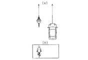
図6(a)は、物体が車両の移動方向に対して直交するように進行するに移動する例を示しており、相対角度であるθは90°である。この場合、撮像装置22から取得した物体の画像は、図6(b)に示すように物体を横から撮像したものとなる。
FIG. 6A shows an example in which the object moves so as to travel orthogonally to the moving direction of the vehicle, and the relative angle θ is 90 °. In this case, the object image acquired from the
すなわち、図4(b)、図5(b)、図6(b)に示すように、車両の進行方向と物体の進行方向との相対角度に応じて、撮像された画像は異なるものとなる。これを利用して、テンプレートマッチングにより相対角度を求めるものとしているのである。 That is, as shown in FIGS. 4B, 5B, and 6B, the captured images differ depending on the relative angle between the traveling direction of the vehicle and the traveling direction of the object. . Using this, the relative angle is obtained by template matching.
テンプレート画像は、物体が自転車であれば、自転車を運転する人に対して設けてもよいし、自転車に対して設けてもよいし、人と自転車を纏めてひとつのテンプレート画像としてもよい。また、テンプレート画像は、所定角度毎に設けられている。このとき、テンプレート画像が設けられる相対角度の間隔は、等間隔であってもよいし、等間隔でなくてもよい。このように所定角度毎にテンプレート画像を設け、テンプレート画像と相対角度とを対応付けるため、例えば実際の相対角度が35°であれば、物体の画像は30°のテンプレート画像との類似度が最も大きくなる可能性が高く、相対角度が30°であると判定される可能性が最も高くなる。 If the object is a bicycle, the template image may be provided for a person driving the bicycle, may be provided for the bicycle, or the person and the bicycle may be combined into a single template image. Moreover, the template image is provided for every predetermined angle. At this time, the relative angle intervals at which the template images are provided may be equal intervals, or may not be equal intervals. In this way, a template image is provided for each predetermined angle, and the template image and the relative angle are associated with each other. For example, if the actual relative angle is 35 °, the object image has the largest similarity to the 30 ° template image. The relative possibility that the relative angle is determined to be 30 ° is the highest.
このようにして、角度取得部16により相対角度が得られれば、その相対角度は上限設定部17へ入力される。上限設定部17では、相対角度に基づいて横速度の上限値を設定する。ここで、横速度の上限値と相対角度との関係について、図7に示す。図7において、車両の進行方向と物体の進行方向とが直交する場合の相対角度を90°と定めており、車両の進行方向と物体の進行方向とが同方向である場合の相対角度を0°と定めており、車両の進行方向と物体の進行方向とが逆方向である場合の相対角度を180°と定めている。物体の横速度は、物体の進行方向への速度が一定であれば、相対角度が90°である場合に最大となり、相対角度が0°に近づくほど、及び、180°に近づくほど小さくなり、相対角度が0°である場合、及び、相対角度が180°である場合にゼロとなる。
When the relative angle is obtained by the
図7に示す相対角度と横速度の上限値との関係は、物体の種別ごとに定められており、物体検知装置10が備えるROMに予め記憶されている。すなわち、物体の種別ごとに、道路上で取り得る速度の上限を最大速度として法令や経験則等に基づいて予め定めておき、その最大速度を相対角度が90°である場合の横速度の上限値として設定する。例えば、物体が自転車である場合には、相対角度が90である場合の最大速度は、例えば、10m/s程度の値に設定されることとなる。
The relationship between the relative angle and the upper limit value of the lateral velocity shown in FIG. 7 is determined for each object type, and is stored in advance in a ROM provided in the
なお、上述した通り、相対角度を求めるうえで、テンプレート画像は所定角度毎に設けられていることから、相対角度の値と横速度の値とを対応付けたテーブルを記憶するものとしてもよい。 As described above, since the template image is provided for each predetermined angle when the relative angle is obtained, a table in which the value of the relative angle and the value of the lateral velocity are associated with each other may be stored.
上限設定部17により物体の横速度の上限値が得られれば、その上限値を領域設定部13へと入力する。領域設定部13では、情報取得部11から取得した横速度が上限値よりも大きければ、横速度を上限値として作動領域を設定する。また、横速度が上限値以下であればそのままの横速度の値を用いて作動領域を設定する。
If the upper limit value of the lateral velocity of the object is obtained by the upper
以上のように構成される物体検知装置10が実行する一連の処理である物体検知方法を、図8のフローチャートを用いて説明する。図8で示すフローチャートは、所定の制御周期ごとに繰り返し実行される。
An object detection method, which is a series of processes executed by the
まず、計測装置21及び撮像装置22から検知情報を取得し、物体の認識処理を行い(S101)、各物体の位置の算出(S102)、及び、縦速度及び横速度の算出を行う(S103)。そして、その位置、及び縦速度に基づいて、衝突予測時間を算出する(S104)。続いて、撮像装置22から取得した画像に基づいて、車両の進行方向に対する物体の進行方向の相対角度を取得し(S105)、その相対角度により横速度の上限値を取得する(S106)。
First, detection information is acquired from the measuring
横速度の上限値が得られれば、計測装置21の計測結果から得られた横速度がその上限値よりも大きいか否かを判定する(S107)。すなわち、計測装置21の計測結果が実際に取り得る横速度から乖離した値であるか否かを判定する。横速度が上限値よりも大きければ(S107:YES)、横速度の値を上限値とする(S108)。一方、横速度が上限値以下であれば(S107:NO)、横速度は実際に取り得る値から乖離しておらず、正しく、もしくは誤差が小さい状態で検出されているといえるため、そのままの値を用いるものとする。このようにして横速度の値が得られれば、横速度に基づいて作動領域を算出し(S109)、作動タイミングを算出する(S110)。
If the upper limit value of the lateral speed is obtained, it is determined whether or not the lateral speed obtained from the measurement result of the measuring
以上のように作動領域が設定されれば、物体の位置が作動領域内であるか否かを判定する(S111)。物体の位置が作動領域内である場合(S111:YES)、安全装置を作動させるひとつの条件を満たしているため、続いて衝突予測時間が作動タイミング以下となったか否かを判定する(S112)。衝突予測時間が作動タイミング以下であれば(S112:YES)、安全装置を作動させる条件をいずれも満たしているため、安全装置を作動させて(S113)、一連の処理を終了する。一方、物体の位置が作動領域内でない場合(S111:NO)、又は、衝突予測時間が作動タイミング以下でない場合(S112:NO)、安全装置を作動させる条件の少なくともひとつを満たしていないため、安全装置を作動させることなく一連の処理を終了する。 If the operation region is set as described above, it is determined whether or not the position of the object is within the operation region (S111). When the position of the object is within the operation region (S111: YES), since one condition for operating the safety device is satisfied, it is subsequently determined whether or not the predicted collision time is less than the operation timing (S112). . If the predicted collision time is equal to or shorter than the operation timing (S112: YES), since all conditions for operating the safety device are satisfied, the safety device is operated (S113), and the series of processes is terminated. On the other hand, when the position of the object is not within the operation region (S111: NO), or when the predicted collision time is not less than the operation timing (S112: NO), at least one of the conditions for operating the safety device is not satisfied. A series of processes is terminated without operating the apparatus.
上記構成により、本実施形態に係る物体検知装置10は以下の効果を奏する。
With the above configuration, the
・探査波の送信及び反射波の受信により物体の横速度を検出する場合、位置の検出のばらつき等により、検出結果に誤差が生ずることがある。この点、本実施形態では、車両の進行方向と物体の進行方向との相対角度により横速度の最大値が定まるという点に着目し、撮像装置22により取得した画像により相対角度を求め、その相対角度により横速度に上限値を設定している。したがって、横速度の検出結果が、横速度の上限値から乖離するような誤検知が生じた場合、精度よくその検知結果を補正することができる。
When detecting the lateral velocity of an object by transmitting an exploration wave and receiving a reflected wave, an error may occur in the detection result due to variations in position detection. In this regard, in this embodiment, focusing on the fact that the maximum value of the lateral velocity is determined by the relative angle between the traveling direction of the vehicle and the traveling direction of the object, the relative angle is obtained from the image acquired by the
・計測装置21の計測結果に基づいて取得する横速度について、撮像装置22の撮像結果により上限値を設定するものとしているため、横方向についての数値の検出誤差が生じやすい計測装置21を、撮像装置22の機能により補完することができる。
Since the upper limit value is set based on the imaging result of the
・物体の種別ごとに横速度の上限値と相対角度との関係を予め設定しておくものであるため、物体の横速度のみならず進行方向への速度の検出も誤検知したとしても、横速度を上限値以下に制限することができる。したがって、より精度よく横速度の誤検知を抑制することができる。 ・ Because the relationship between the upper limit of the lateral velocity and the relative angle is set in advance for each object type, even if the detection of not only the lateral velocity of the object but also the velocity in the traveling direction is erroneously detected, The speed can be limited to an upper limit value or less. Therefore, it is possible to suppress erroneous detection of the lateral speed with higher accuracy.
・物体の横速度により作動領域の幅を変更しているため、横速度の誤検知を抑制することにより、安全装置の不要作動を抑制することができる。 -Since the width | variety of an action | operation area | region is changed with the lateral speed of the object, the unnecessary operation | movement of a safety device can be suppressed by suppressing the misdetection of a lateral speed.
<変形例>
・実施形態では、横速度の上限値を定めるうえで、相対角度が90°である場合を最大とし、相対角度が0°、180°へそれぞれ向かううえで直線的に漸減するように設定している、横速度の上限値と相対角度との関係は実施形態に示したものに限られない。例えば、横速度の上限値を段階的に変化させるものとしてもよい。また、横速度は進行方向への速度に正弦を乗算したものであるから、横速度の上限値を、相対角度が90°である場合を極大値とし、相対角度が0°と180°の場合を0をする正弦波に基づくものとしてもよい。また、他の設定方法を採用してもよい。
<Modification>
In the embodiment, when determining the upper limit value of the lateral velocity, the maximum is set when the relative angle is 90 °, and the relative angle is set so as to gradually decrease linearly toward each of 0 ° and 180 °. The relationship between the upper limit value of the lateral speed and the relative angle is not limited to that shown in the embodiment. For example, the upper limit value of the lateral speed may be changed stepwise. In addition, since the lateral speed is obtained by multiplying the speed in the traveling direction by a sine, the upper limit value of the lateral speed is the maximum when the relative angle is 90 °, and the relative angle is 0 ° and 180 °. May be based on a sine wave with zero. Other setting methods may be adopted.
・実施形態では、相対角度が0°である場合、及び180°である場合に横速度の上限値を0としたが、0よりも大きい値としてもよい。実施形態で述べたとおり、相対角度を求めるうえで、所定角度毎に設けられたテンプレート画像を用いるものとしているため、相対角度が0°であると判定されたとしても、実際の相対角度は0°又は0°近傍の値である。したがって、横速度として0よりも大きな値が検出されることが多くなる。実施形態に係る物体検知装置10は、横速度の値として実際の値から乖離したものが検出された場合にその値を排除するものであるから、実際の横速度に近い値を排除する必要性は無い。したがって、上述したとおり、相対角度が0°である場合、及び180°である場合に横速度の上限値を0よりも大きい値としてもよい。
In the embodiment, the upper limit value of the lateral speed is set to 0 when the relative angle is 0 ° and when the relative angle is 180 °, but may be a value larger than 0. As described in the embodiment, since the template image provided for each predetermined angle is used to obtain the relative angle, even if it is determined that the relative angle is 0 °, the actual relative angle is 0. It is a value in the vicinity of ° or 0 °. Therefore, a value larger than 0 is often detected as the lateral speed. The
・実施形態では、相対角度と横速度の上限値との関係について、90°の場合を最大値とし、0°に近づく場合と180°に近づく場合と等しい変化量で上限値を小さくするものとしたが、それらの変化量は等しくなくてもよい。 In the embodiment, with respect to the relationship between the relative angle and the upper limit value of the lateral velocity, the maximum value is set at 90 °, and the upper limit value is reduced by the same amount of change as when approaching 0 ° and approaching 180 °. However, the amount of change need not be equal.
・物体の横速度の誤検知が特に問題となるのは、図3で示したような、物体が車両の進路に割り込む場合であり、この場合には、車両の進行方向と物体の進行方向との相対角度は90°よりも0°に近い値となる。したがって、相対角度と横速度の上限値との関係を図9に示すものとしてもよい。すなわち、相対角度が0°に近い範囲においては実施形態のごとく設定し、横速度の誤検知が有った場合には横速度を上限値としやすくし、相対角度が90°に近い範囲においては、上限値を最大速度よりも大きく設定し、横速度が最大速度よりも大きくなる事態を抑制するものとしてもよい。また、図10に示すように、90°前後の所定範囲Δθについては、横速度の上限値を設けないものとしてもよい。なお、図9及び図10において、実施形態における相対角度と横速度の上限値との関係を、破線で示している。 -The erroneous detection of the lateral velocity of the object is particularly problematic when the object interrupts the course of the vehicle as shown in FIG. 3, and in this case, the traveling direction of the vehicle and the traveling direction of the object Is a value closer to 0 ° than 90 °. Therefore, the relationship between the relative angle and the upper limit value of the lateral speed may be as shown in FIG. That is, in the range where the relative angle is close to 0 °, it is set as in the embodiment, and when the lateral speed is erroneously detected, the lateral speed is easily set as the upper limit value, and in the range where the relative angle is close to 90 °. The upper limit value may be set larger than the maximum speed to suppress the situation where the lateral speed becomes larger than the maximum speed. Further, as shown in FIG. 10, the upper limit value of the lateral speed may not be provided for the predetermined range Δθ around 90 °. 9 and 10, the relationship between the relative angle and the upper limit value of the lateral velocity in the embodiment is indicated by a broken line.
・実施形態では、車両の移動方向と物体の移動方向とが直交する場合の相対角度を90°と定義したが、角度の値をどのように定義するかは任意である。例えば、車両の移動方向と物体の移動方向とが直交する場合の相対角度を0°と定義してもよい。 In the embodiment, the relative angle when the moving direction of the vehicle and the moving direction of the object are orthogonal is defined as 90 °. However, how to define the value of the angle is arbitrary. For example, the relative angle when the moving direction of the vehicle and the moving direction of the object are orthogonal may be defined as 0 °.
・実施形態では、物体の種別ごとに横速度の上限値と相対角度との関係を記憶部に予め記憶させておき、検出された物体の種別及び相対角度に基づいて、記憶部から相対角度の値を読み出すものとしている。この点、物体の進行方向への速度に基づいて、横速度の上限値を設定するものとしてもよい。 In the embodiment, the relationship between the upper limit value of the lateral speed and the relative angle is stored in advance in the storage unit for each type of object, and the relative angle is calculated from the storage unit based on the detected object type and relative angle. The value is to be read. In this respect, the upper limit value of the lateral speed may be set based on the speed of the object in the traveling direction.
・実施形態では、横速度を用いて作動領域の幅を設定するものとした。この点、実施形態で述べたように、物体の横速度が大きいほど物体が車両の進路に進入する可能性が高く、また、運転者が物体を認識できない可能性が高い。そのため、横速度が大きいほど安全装置の作動タイミングを大きく設定し、縦距離が大きい場合にも安全装置が作動するようにしてもよい。 In the embodiment, the width of the operation region is set using the lateral speed. In this regard, as described in the embodiment, the higher the lateral velocity of the object, the higher the possibility that the object will enter the vehicle path, and the higher the possibility that the driver cannot recognize the object. Therefore, the operation timing of the safety device may be set larger as the lateral speed is larger, and the safety device may be operated even when the vertical distance is large.
・実施形態では、車両の進行方向と物体の進行方向との相対角度を0°から180°の間で求めるものとしたが、物体の進行方向が横方向について遠ざかるものである場合にもついても相対角度を求め、遠ざかる方向への横速度についても上限値を設定するものとしてもよい。 In the embodiment, the relative angle between the traveling direction of the vehicle and the traveling direction of the object is obtained between 0 ° and 180 °. However, even in the case where the traveling direction of the object is away from the lateral direction. It is good also as what calculates | requires a relative angle and sets an upper limit also about the lateral velocity to the direction to go away.
・実施形態では、車両の進行方向と物体の進行方向との相対角度を撮像装置22により取得した画像に基づいて求めているが、他の方法により求めることもできる。例えば、物体の位置の履歴から進行方向を求めるものとしてもよい。
In the embodiment, the relative angle between the traveling direction of the vehicle and the traveling direction of the object is obtained based on the image acquired by the
・実施形態では、車両の進行方向に対する物体の進行方向の相対角度を求めるものとしているが、相対角度の取得は必須の構成ではない。すなわち、テンプレートマッチングを行う際に用いるテンプレート画像に相対角度ではなく横速度の上限値を対応付けておき、相対角度を取得することなく横速度の上限値を取得するものとしてもよい。この場合においても、車両の進行方向と物体の進行方向との関係により、横速度の上限値を取得するものであるため、角度取得部16を関係取得部と言い換えることができる。
-In embodiment, although the relative angle of the advancing direction of the object with respect to the advancing direction of a vehicle is calculated | required, acquisition of a relative angle is not an essential structure. That is, it is possible to associate the upper limit value of the lateral velocity instead of the relative angle with the template image used when performing template matching, and acquire the upper limit value of the lateral velocity without acquiring the relative angle. Also in this case, since the upper limit value of the lateral speed is acquired based on the relationship between the traveling direction of the vehicle and the traveling direction of the object, the
・実施形態では、車両の進行方向に直交する方向についての物体の速度を横速度とし、車両の進行方向と物体の進行方向とのなす角度により、横速度の上限値を定めている。この点、車両の進行方向に限らず、車両の所定方向に直交する方向についての物体の速度を横速度とし、車両の所定方向と物体の進行方向となす角度により、横速度の上限値を定めてもよい。この場合、車両は移動していてもよいし、移動していなくてもよい。 In the embodiment, the speed of the object in the direction orthogonal to the traveling direction of the vehicle is the lateral speed, and the upper limit value of the lateral speed is determined by the angle formed by the traveling direction of the vehicle and the traveling direction of the object. In this respect, the upper limit of the lateral speed is determined by the lateral speed, which is the speed of the object in a direction orthogonal to the predetermined direction of the vehicle, not limited to the traveling direction of the vehicle, and the angle between the predetermined direction of the vehicle and the traveling direction of the object May be. In this case, the vehicle may be moving or may not be moving.
・実施形態では、物体の例として自転車を挙げているが、歩行者、自動二輪車、自動車等、車両の周囲の移動体に対して同様に適用することができる。 In the embodiment, a bicycle is cited as an example of the object, but the present invention can be similarly applied to a moving body around the vehicle, such as a pedestrian, a motorcycle, and an automobile.
・実施形態では、物体の横速度を用いて安全装置の作動領域の幅を設定するものとしているが、横速度の用途はこれに限られない。例えば、車両を進行方向前方を走行する他車に追従走行させる機能を実現するうえで、実施形態に係る物体検知装置10の機能を採用するものとしてもよい。
In the embodiment, the width of the operation region of the safety device is set using the lateral speed of the object, but the use of the lateral speed is not limited to this. For example, the function of the
・実施形態及び上記各変形例では、物体の横速度を物体速度値として上限値を設定するとともに、その横速度を用いて領域の幅を設定するものとしている。この点、物体の横速度の代わりに横方向への加速度である横加速度を物体速度値として取得し、その横加速度に上限値を設定するとともに、横加速度を用いて領域の幅を設定するものとしてもよい。この場合には、相対角度が90°である場合の上限値を最大加速度とすればよい。また、物体の横速度及び横加速度を共に物体速度値として取得し、横速度及び横加速度のそれぞれに上限値を設定するものとしてもよい。 In the embodiment and each of the modifications described above, the upper limit value is set with the lateral velocity of the object as the object velocity value, and the width of the region is set using the lateral velocity. In this regard, the lateral acceleration that is the lateral acceleration instead of the lateral velocity of the object is acquired as the object velocity value, and an upper limit value is set for the lateral acceleration, and the width of the region is set using the lateral acceleration. It is good. In this case, the upper limit value when the relative angle is 90 ° may be the maximum acceleration. Alternatively, both the lateral velocity and the lateral acceleration of the object may be acquired as the object velocity values, and an upper limit value may be set for each of the lateral velocity and the lateral acceleration.
・実施形態では、物体検知装置10が車両に搭載されるものとしたが、搭載対象物は車両に限られることはなく、様々な移動体に搭載することができる。また、物体検知装置10の搭載対象物は移動体に限られず、静止物であってもよい。この場合には、搭載対象物の周囲の物体の移動方向や移動速度を監視する装置として用いることができる。
In the embodiment, the
10…物体検知装置、11…情報取得部、13…領域設定部、16…角度取得部、17…上限設定部、21…計測装置、22…撮像装置。
DESCRIPTION OF
Claims (8)
周囲に探査波を送信し前記物体により反射された反射波を受信する計測装置(21)の計測結果に基づいて、前記自己の周囲の所定方向に対して直交する方向である横方向における、前記物体の速度及び加速度の少なくとも一方である物体速度値を取得する速度取得部(11)と、
前記所定方向に対する前記物体の移動方向の角度を示す関係である角度情報に基づいて、前記物体速度値の上限を設定する上限設定部(17)と、
前記物体の前記所定方向に対する姿勢を表す姿勢角度について、それぞれ1又は複数のテンプレート画像を予め記憶しておき、周囲を撮像する撮像装置(22)から前記物体の画像を取得し、前記テンプレート画像と前記物体の画像とのテンプレートマッチングを行い、最も類似度の高い前記テンプレート画像に対応付けられた前記姿勢角度を前記角度情報とする角度取得部と、を備え、
前記上限設定部は、前記物体の種別を取得し、取得した前記種別及び前記関係に基づいて前記上限を設定し、
前記種別ごとに前記移動方向への最大速度及び最大加速度の少なくとも一方が予め定められており、
前記上限設定部は、前記関係が直交を含む所定の角度範囲内であることを示す場合、前記上限を前記最大速度及び最大加速度の少なくとも一方よりも大きい値に設定する物体検知装置。 An object detection device (10) for detecting an object moving around itself,
Based on the measurement result of the measurement device (21) that transmits the exploration wave to the surroundings and receives the reflected wave reflected by the object, in the lateral direction that is a direction orthogonal to the predetermined direction around the self, A speed acquisition unit (11) that acquires an object speed value that is at least one of the speed and acceleration of the object;
An upper limit setting unit (17) that sets an upper limit of the object speed value based on angle information that is a relationship indicating an angle of the moving direction of the object with respect to the predetermined direction;
One or a plurality of template images are stored in advance for each posture angle representing the posture of the object with respect to the predetermined direction, an image of the object is acquired from an imaging device (22) that captures the surroundings, and the template image and An angle acquisition unit that performs template matching with the image of the object and uses the posture angle associated with the template image with the highest similarity as the angle information ,
The upper limit setting unit acquires the type of the object, sets the upper limit based on the acquired type and the relationship,
For each of the types, at least one of a maximum speed and a maximum acceleration in the moving direction is predetermined,
The said upper limit setting part is an object detection apparatus which sets the said upper limit to a value larger than at least one of the said maximum speed and the maximum acceleration, when showing that the said relationship is in the predetermined angle range containing orthogonality .
前記自己の周囲の所定方向に対して直交する方向である横方向における、前記物体の速度及び加速度の少なくとも一方である物体速度値を取得する速度取得部(11)と、
前記所定方向に対する前記物体の移動方向の角度を示す関係である角度情報に基づいて、前記物体速度値の上限を設定する上限設定部(17)と、を備え、
前記上限設定部は、前記物体の種別を取得し、取得した前記種別及び前記関係に基づいて前記上限を設定し、
前記種別ごとに前記移動方向への最大速度及び最大加速度の少なくとも一方が予め定められており、
前記上限設定部は、前記関係が直交を含む所定の角度範囲内であることを示す場合、前記上限を前記最大速度及び最大加速度の少なくとも一方よりも大きい値に設定する、物体検知装置。 An object detection device (10) for detecting an object moving around itself,
A speed acquisition unit (11) that acquires an object speed value that is at least one of the speed and acceleration of the object in a lateral direction that is a direction orthogonal to a predetermined direction around the self;
An upper limit setting unit (17) that sets an upper limit of the object speed value based on angle information that is a relationship indicating an angle of the moving direction of the object with respect to the predetermined direction,
The upper limit setting unit acquires the type of the object, sets the upper limit based on the acquired type and the relationship,
For each of the types, at least one of a maximum speed and a maximum acceleration in the moving direction is predetermined,
The said upper limit setting part is an object detection apparatus which sets the said upper limit to a value larger than at least one of the said maximum speed and the maximum acceleration, when showing that the said relationship is in the predetermined angle range containing orthogonality.
前記上限設定部は、周囲を撮像する撮像装置(22)から前記物体の画像を取得し、その画像に基づいて前記角度情報を取得する、請求項2に記載の物体検知装置。 The velocity acquisition unit acquires the object velocity value based on a measurement result of a measurement device (21) that transmits an exploration wave to the surroundings and receives a reflected wave reflected by the object,
The object detection device according to claim 2 , wherein the upper limit setting unit acquires an image of the object from an imaging device (22) that captures an image of the surroundings, and acquires the angle information based on the image.
前記速度取得部は、前記移動体の移動方向に対して直交する横方向において前記移動体の側への前記物体速度値を取得し、
前記上限設定部は、前記移動体の移動方向に対する前記物体の移動方向の相対角度を示す関係である角度情報に基づいて、前記物体速度値の上限を設定する、請求項1〜5のいずれか1項に記載の物体検知装置。 The self is a moving body;
The speed acquisition unit acquires the object speed value toward the moving body in a lateral direction orthogonal to the moving direction of the moving body,
Upper limit setting unit, on the basis of the angle information is a relationship that indicates the relative angle of the direction of movement of the object relative to the moving direction of the moving body, setting an upper limit of the object speed values, one of claims 1 to 5 The object detection device according to item 1.
前記物体が前記領域内に位置する場合、前記移動体と前記物体とが衝突する可能性があると判定する判定部(15)と、をさらに備え、
前記領域設定部は、前記物体速度値が大きいほど、前記領域の幅を大きく設定する、請求項6に記載の物体検知装置。 An area setting unit (13) for setting an area having a width in front of the moving body in the moving direction;
A determination unit (15) that determines that the moving object and the object may collide when the object is located in the region;
The object detection device according to claim 6 , wherein the area setting unit sets the width of the area to be larger as the object speed value is larger.
前記自己の周囲の所定方向に対して直交する方向である横方向における、前記物体の速度及び加速度の少なくとも一方である物体速度値を取得する速度取得ステップと、
前記物体の種別を取得し、取得した前記種別、及び前記所定方向に対する前記物体の移動方向の角度を示す関係である角度情報に基づいて、前記物体速度値の上限を設定する上限設定ステップと、
前記種別ごとに前記移動方向への最大速度及び最大加速度の少なくとも一方を予め定めておくステップと、
前記上限設定ステップにおいて、前記関係が直交を含む所定の角度範囲内であることを示す場合、前記上限を前記最大速度及び最大加速度の少なくとも一方よりも大きい値に設定するステップと、を実行する物体検知方法。 An object detection method executed by an object detection device (10) for detecting an object moving around itself,
A speed acquisition step of acquiring an object speed value that is at least one of the speed and acceleration of the object in a lateral direction that is a direction orthogonal to a predetermined direction around the self;
An upper limit setting step of acquiring the type of the object, and setting an upper limit of the object speed value based on the acquired type and angle information which is a relationship indicating an angle of the moving direction of the object with respect to the predetermined direction;
Predetermining at least one of a maximum speed and a maximum acceleration in the moving direction for each type;
An object that executes the step of setting the upper limit to a value larger than at least one of the maximum speed and the maximum acceleration when the upper limit setting step indicates that the relationship is within a predetermined angular range including orthogonality; Detection method.
Priority Applications (3)
| Application Number | Priority Date | Filing Date | Title |
|---|---|---|---|
| JP2015246691A JP6477453B2 (en) | 2015-12-17 | 2015-12-17 | Object detection device and object detection method |
| US16/062,522 US10960877B2 (en) | 2015-12-17 | 2016-11-28 | Object detection device and object detection method |
| PCT/JP2016/085097 WO2017104387A1 (en) | 2015-12-17 | 2016-11-28 | Object detection device and object detection method |
Applications Claiming Priority (1)
| Application Number | Priority Date | Filing Date | Title |
|---|---|---|---|
| JP2015246691A JP6477453B2 (en) | 2015-12-17 | 2015-12-17 | Object detection device and object detection method |
Publications (3)
| Publication Number | Publication Date |
|---|---|
| JP2017111682A JP2017111682A (en) | 2017-06-22 |
| JP2017111682A5 JP2017111682A5 (en) | 2018-02-22 |
| JP6477453B2 true JP6477453B2 (en) | 2019-03-06 |
Family
ID=59056257
Family Applications (1)
| Application Number | Title | Priority Date | Filing Date |
|---|---|---|---|
| JP2015246691A Active JP6477453B2 (en) | 2015-12-17 | 2015-12-17 | Object detection device and object detection method |
Country Status (3)
| Country | Link |
|---|---|
| US (1) | US10960877B2 (en) |
| JP (1) | JP6477453B2 (en) |
| WO (1) | WO2017104387A1 (en) |
Families Citing this family (9)
| Publication number | Priority date | Publication date | Assignee | Title |
|---|---|---|---|---|
| JP6729282B2 (en) * | 2016-10-18 | 2020-07-22 | 株式会社デンソー | Vehicle control device |
| DE102017205030A1 (en) * | 2017-03-24 | 2018-09-27 | Volkswagen Aktiengesellschaft | Driver assistance system based steering assistance system, steering assistance system and vehicle |
| US11644556B2 (en) * | 2017-06-20 | 2023-05-09 | Nec Corporation | Position measurement device, position measurement method, and program recording medium |
| KR102054926B1 (en) * | 2018-02-27 | 2019-12-12 | 주식회사 만도 | System and method for detecting close cut-in vehicle based on free space signal |
| CN111497837B (en) * | 2019-01-29 | 2022-07-19 | 宇通客车股份有限公司 | Vehicle control method and system based on forward sensing |
| DE102019120022A1 (en) * | 2019-07-24 | 2021-01-28 | Jungheinrich Aktiengesellschaft | Industrial truck with object recognition |
| CN111409631B (en) * | 2020-04-10 | 2022-01-11 | 新石器慧通(北京)科技有限公司 | Vehicle running control method and device, vehicle and storage medium |
| JP2022032109A (en) * | 2020-08-11 | 2022-02-25 | 株式会社デンソー | Collision determination device, collision determination method, and collision avoidance system |
| KR20230055722A (en) * | 2021-10-19 | 2023-04-26 | 현대모비스 주식회사 | A target detection system and method of a vehicle |
Family Cites Families (9)
| Publication number | Priority date | Publication date | Assignee | Title |
|---|---|---|---|---|
| DE10235414A1 (en) * | 2002-08-02 | 2004-02-12 | Robert Bosch Gmbh | Method and device for determining the impending inevitable collision |
| WO2005037592A1 (en) | 2003-09-23 | 2005-04-28 | Daimlerchrysler Ag | Method and device for recognising lane changing operations for a motor vehicle |
| JP5111321B2 (en) * | 2008-10-06 | 2013-01-09 | 株式会社豊田中央研究所 | 瞼 Likelihood calculation device and program |
| DE102008062916A1 (en) * | 2008-12-23 | 2010-06-24 | Continental Safety Engineering International Gmbh | Method for determining a collision probability of a vehicle with a living being |
| JP5387531B2 (en) * | 2010-08-26 | 2014-01-15 | 株式会社デンソー | Driving support device |
| JP5482672B2 (en) | 2011-01-12 | 2014-05-07 | 株式会社デンソーアイティーラボラトリ | Moving object detection device |
| JP6175846B2 (en) * | 2013-03-27 | 2017-08-09 | 富士通株式会社 | Vehicle tracking program, server device, and vehicle tracking method |
| JP5905846B2 (en) * | 2013-03-29 | 2016-04-20 | 株式会社日本自動車部品総合研究所 | Crossing determination device and program |
| JP6397934B2 (en) * | 2014-12-19 | 2018-09-26 | 株式会社日立製作所 | Travel control device |
-
2015
- 2015-12-17 JP JP2015246691A patent/JP6477453B2/en active Active
-
2016
- 2016-11-28 WO PCT/JP2016/085097 patent/WO2017104387A1/en active Application Filing
- 2016-11-28 US US16/062,522 patent/US10960877B2/en active Active
Also Published As
| Publication number | Publication date |
|---|---|
| US10960877B2 (en) | 2021-03-30 |
| JP2017111682A (en) | 2017-06-22 |
| WO2017104387A1 (en) | 2017-06-22 |
| US20180370531A1 (en) | 2018-12-27 |
Similar Documents
| Publication | Publication Date | Title |
|---|---|---|
| JP6477453B2 (en) | Object detection device and object detection method | |
| JP6561584B2 (en) | Vehicle control apparatus and vehicle control method | |
| JP6536521B2 (en) | Object detection apparatus and object detection method | |
| JP6432447B2 (en) | Vehicle control apparatus and vehicle control method | |
| JP6581379B2 (en) | Vehicle control apparatus and vehicle control method | |
| JP6504042B2 (en) | Control device, control method | |
| US10661793B2 (en) | Vehicle control apparatus and vehicle control method | |
| JP6451623B2 (en) | Driving support device | |
| US9470790B2 (en) | Collision determination device and collision determination method | |
| JP6493196B2 (en) | Control device and control method | |
| JP6432482B2 (en) | Vehicle control apparatus and vehicle control method | |
| JP6855776B2 (en) | Object detection device and object detection method | |
| WO2016158970A1 (en) | Object detection device and object detection method | |
| JP6319181B2 (en) | Vehicle control apparatus and vehicle control method | |
| WO2017171082A1 (en) | Vehicle control device and vehicle control method | |
| JP2016192166A (en) | Vehicle control device and vehicle control method | |
| JP2017117344A (en) | Travel support device | |
| JP2019052920A (en) | Object detector, object detection method and vehicle control system | |
| JP6432538B2 (en) | Collision prediction device | |
| JP2016192167A (en) | Vehicle control device and vehicle control method | |
| JP2017151726A (en) | Collision predicting device | |
| JP6462610B2 (en) | Crossing judgment device | |
| JP7265971B2 (en) | Control device |
Legal Events
| Date | Code | Title | Description |
|---|---|---|---|
| A521 | Request for written amendment filed |
Free format text: JAPANESE INTERMEDIATE CODE: A523 Effective date: 20180111 |
|
| A621 | Written request for application examination |
Free format text: JAPANESE INTERMEDIATE CODE: A621 Effective date: 20180111 |
|
| A131 | Notification of reasons for refusal |
Free format text: JAPANESE INTERMEDIATE CODE: A131 Effective date: 20181023 |
|
| A521 | Request for written amendment filed |
Free format text: JAPANESE INTERMEDIATE CODE: A523 Effective date: 20181206 |
|
| TRDD | Decision of grant or rejection written | ||
| A01 | Written decision to grant a patent or to grant a registration (utility model) |
Free format text: JAPANESE INTERMEDIATE CODE: A01 Effective date: 20190108 |
|
| A61 | First payment of annual fees (during grant procedure) |
Free format text: JAPANESE INTERMEDIATE CODE: A61 Effective date: 20190121 |
|
| R151 | Written notification of patent or utility model registration |
Ref document number: 6477453 Country of ref document: JP Free format text: JAPANESE INTERMEDIATE CODE: R151 |
|
| R250 | Receipt of annual fees |
Free format text: JAPANESE INTERMEDIATE CODE: R250 |
|
| R250 | Receipt of annual fees |
Free format text: JAPANESE INTERMEDIATE CODE: R250 |
|
| R250 | Receipt of annual fees |
Free format text: JAPANESE INTERMEDIATE CODE: R250 |