JP6477340B2 - Road boundary detection device, self-position estimation device, and road boundary detection method - Google Patents
Road boundary detection device, self-position estimation device, and road boundary detection method Download PDFInfo
- Publication number
- JP6477340B2 JP6477340B2 JP2015153852A JP2015153852A JP6477340B2 JP 6477340 B2 JP6477340 B2 JP 6477340B2 JP 2015153852 A JP2015153852 A JP 2015153852A JP 2015153852 A JP2015153852 A JP 2015153852A JP 6477340 B2 JP6477340 B2 JP 6477340B2
- Authority
- JP
- Japan
- Prior art keywords
- boundary
- road
- slope
- road surface
- boundary detection
- Prior art date
- Legal status (The legal status is an assumption and is not a legal conclusion. Google has not performed a legal analysis and makes no representation as to the accuracy of the status listed.)
- Active
Links
Images


Description
本発明は、道路境界検出装置、自己位置推定装置及び道路境界検出方法に関するものである。 The present invention relates to a road boundary detection device, a self-position estimation device, and a road boundary detection method.
カメラ画像から路面の高さ情報を検出し、この高さ情報から縁石などの路側物により生じる路面の段差を検出する路側物検出装置が知られている(特許文献1参照)。 A roadside object detection device that detects road surface height information from a camera image and detects a road surface level difference caused by a roadside object such as a curb from this height information is known (see Patent Document 1).
上記した路側物検出装置は、路面の高さ変化量が閾値以上であった場合に段差として認識する。よって、車両が車道から敷地へ進入可能な場所に縁石の代わりにスロープが設けられている場合、スロープを越えて先にある段差を誤って検出してしまい、道路境界を正しく検出することができないことがある。 The roadside object detection device described above recognizes a step when the amount of change in the height of the road surface is equal to or greater than a threshold value. Therefore, when a slope is provided instead of a curb at a place where the vehicle can enter the site from the roadway, a step difference beyond the slope is erroneously detected, and the road boundary cannot be detected correctly. Sometimes.
本発明は、上記課題に鑑みて成されたものであり、その目的は、道路境界の検出精度が向上する道路境界検出装置、自己位置推定装置及び道路境界検出方法を提供することである。 The present invention has been made in view of the above problems, and an object of the present invention is to provide a road boundary detection device, a self-position estimation device, and a road boundary detection method that improve the detection accuracy of the road boundary.
本発明の一態様に係わる道路境界検出装置は、車両の周囲における路面の高さを検出する測距部を備える。そして、道路境界検出装置は、路面の高さに基づいて段差を検出し、路面の車幅方向の所定範囲において段差が検出されなかった場合、路面の車幅方向の勾配に基づいて、スロープと車道との境界を検出し、スロープと車道との境界或いは段差を道路境界と推定する。 A road boundary detection apparatus according to an aspect of the present invention includes a distance measuring unit that detects the height of a road surface around a vehicle. The road boundary detection device detects a step based on the height of the road surface, and if no step is detected in a predetermined range in the vehicle width direction of the road surface, the road boundary detection device detects the slope based on the gradient of the road surface in the vehicle width direction. The boundary with the roadway is detected, and the boundary or step between the slope and the roadway is estimated as the road boundary.
本発明の一態様によれば、段差の代わりにスロープが設けられた場所において、スロープと車道との境界を道路境界として検出することができる。よって、道路境界の検出精度が向上する。 According to one embodiment of the present invention, a boundary between a slope and a roadway can be detected as a road boundary at a place where a slope is provided instead of a step. Therefore, the road boundary detection accuracy is improved.
(第1実施形態)
次に、図面を参照して、本発明の実施の形態を詳細に説明する。
(First embodiment)
Next, embodiments of the present invention will be described in detail with reference to the drawings.
図1を参照して、第1実施形態に係わる道路境界検出装置1の全体構成を説明する。道路境界検出装置1は、車両の周囲における道路の表面(以後、「路面」という)の高さを検出し、路面の高さ変化に基づいて路面上の段差を検出する。路面の車幅方向の所定範囲において段差が検出されなかった場合、道路境界検出装置1は、段差の代わりにスロープが設けられている可能性があると判断する。そして、路面の車幅方向の勾配に基づいて、スロープと車道との境界を検出する。このように、道路境界検出装置1は、所定範囲において段差の検出を試み、検出されなかった場合に、スロープと車道との境界を検出することにより、道路境界を精度良く検出する。
With reference to FIG. 1, the whole structure of the road
具体的に、道路境界検出装置1は、車両の周囲における路面の高さを検出する測距センサ12と、測距センサ12による測定データから道路境界を検出する一連の情報処理を実行するマイクロコンピュータ13とを備える。
Specifically, the road
測距センサ12の一例は、車両の周囲にある物体を複数の異なる方向から同時に撮影することにより、車両の周囲にある物体の奥行き方向(センサ12からの距離)の情報も記録することができるステレオカメラである。ステレオカメラにより得られたステレオ画像に対して所定の画像処理を施すことにより、車両の周囲にある物体のステレオ画像に映る物体の像に対する三次元情報を取得することができる。車両の周囲にある物体には、道路や縁石が含まれる。詳細は、後述する。
An example of the
マイクロコンピュータ13は、例えば、CPU、メモリ、及び入出力部を備える汎用のマイクロコントローラからなり、予めインストールされたコンピュータプログラムを実行することにより、道路境界検出装置1が備える複数の情報処理回路を構成する。マイクロコンピュータ13は、測距センサ12による測定データから道路境界を検出する一連の情報処理サイクルを所定の時間間隔で繰り返し実行する。マイクロコンピュータ13は、車両にかかわる他の制御に用いる電子制御ユニット(ECU)と兼用してもよい。
The
マイクロコンピュータ13により構成される複数の情報処理回路には、演算回路14と、段差判定位置回路15と、段差検出回路18と、スロープ境界検出回路19と、道路境界推定回路20とが含まれる。
The plurality of information processing circuits configured by the
演算回路14は、測距センサ12と共に測距部11を構成し、ステレオカメラにより得られたステレオ画像から車両周囲の物体のステレオ画像に映る物体の像に対する三次元情報を取得する一連のステレオ画像処理を実施する。
The
例えば、演算回路14は、ステレオ画像に対してレンズの歪みを補正するレンズ歪み補正処理を行い、ステレオ画像間の上下位置を補正する平行化補正処理(平行等位処理)を行う。そして、ステレオ画像間の各画素の対応付けを推定するステレオマッチング処理を行う。これにより、ステレオカメラの撮像面における物体の二次元座標のみならず、ステレオカメラの撮像面から物体までの距離を算出することができる。よって、車両周囲にある物体までの距離及び方位を検出することができる。
For example, the
演算回路14は、更に座標変換処理を施すことにより、測距データの座標上の車両周囲にある物体の三次元情報を取得することができる。車両周囲にある物体の三次元情報には、車両の周囲における路面の三次元情報も含まれる。よって、演算回路14は、車両の周囲における路面の高さを取得することができる。
The
レンズ歪み補正処理は、例えば黒白の市松模様のパターンを表した平板を各カメラで撮影し、市松模様の格子点が矩形で構成される格子状となるようにレンズ歪みパラメータやカメラレンズ中心パラメータを推定する。ただし、本処理は、レンズ歪み補正を行う一般的な手法でよく、本実施形態では特に問わない。 In the lens distortion correction process, for example, a flat plate representing a black and white checkered pattern is photographed by each camera, and the lens distortion parameter and the camera lens center parameter are set so that the checkered grid points are formed in a rectangular grid. presume. However, this processing may be a general method for correcting lens distortion, and is not particularly limited in the present embodiment.
平行化補正処理は、例えば黒白の市松模様のパターンを表した平板をステレオカメラの両カメラで撮影し、市松模様の格子点の位置が各カメラ画像上で同じ上下位置になるようにステレオカメラ間の空間位置パラメータ及び角度パラメータを推定する。ただし、本処理は、平行化補正処理を行う一般的な手法でよく、本実施形態では特に問わない。 Parallelization correction processing is performed by taking a flat plate representing a black and white checkered pattern with both cameras of the stereo camera, for example, so that the positions of the checkered lattice points are the same vertical position on each camera image. The spatial position parameter and the angle parameter are estimated. However, this process may be a general technique for performing the parallelization correction process, and is not particularly limited in the present embodiment.
ステレオマッチング処理は、例えば、左カメラ画像を基準として左カメラ画像の各画素が右カメラ画像のどの画素に対応付けされるかを算出するものである。例えば、左カメラ画像の各画素の輝度値と右カメラ画像の各画素の輝度値の絶対値を評価値として算出して、評価値が最小となる右カメラ画像の画素を対応付けされた画素として算出する。評価値の算出方法には、例えば、差分絶対値の和(SAD:Sum of Absolute Differences)や差分二乗値の和(SSD:Sum of Squared Differences)を用いる方法や、評価値計算の範囲が各画素1点でなく各画素の周辺画素を含む方法がある。評価値の算出方法は、他の一般的な方式でもよく、本実施形態では特に問わない。 In the stereo matching process, for example, each pixel of the left camera image is associated with which pixel of the right camera image with reference to the left camera image. For example, the absolute value of the luminance value of each pixel of the left camera image and the luminance value of each pixel of the right camera image is calculated as an evaluation value, and the pixel of the right camera image having the smallest evaluation value is associated with the pixel. calculate. The evaluation value calculation method includes, for example, a method using a sum of absolute difference values (SAD: Sum of Absolute Differences) or a sum of squared difference values (SSD: Sum of Squared Differences), and a range of evaluation value calculation for each pixel. There is a method including peripheral pixels of each pixel instead of one point. The calculation method of the evaluation value may be another general method and is not particularly limited in the present embodiment.
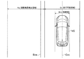
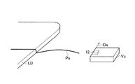
段差判定位置回路15は、測距センサ12で検出された測距データの座標上の車両の周囲の路面に車幅方向の線状の段差判定位置を設定する。例えば、図2及び図3に示すように、測距センサ12から第1の所定方向(Da)に所定距離だけ離れ、第1の所定方向(Da)に直交する方向に延びる段差判定位置(Pa)を測距データの座標上の路面に設定する。図2及び図3は、車両(Vc)の前部に測距センサ12を設置し、車両(Vc)の進行方向を第1の所定方向(Da)とした例を示す。よって、車幅方向に延びる段差判定位置(Pa)が、測距データの座標上の車両(Vc)の前方に設定される。なお、段差判定位置(Pa)は、ステレオカメラの撮像範囲内において設定される。第1の所定方向(Da)は車両(Vc)の進行方向に限定されない。
The step
図2及び図3に示す例で、車両(Vc)が走行可能な車道の車幅方向の端部である路肩には、路面の高さが非連続的に変化する段差(LD)が形成されている。そして、段差(LD)を境にして車道よりも外側には、車道よりも路面が一段高い段差部(例えば、歩道や路肩)が設けられている。このように、図2及び図3に示す例において、道路は、車道及び段差部(歩道や路肩)からなり、車道と段差部(歩道や路肩)の境界には、段差(LD)が形成されている。線状の段差判定位置(Pa)は、車道、段差(LD)、及び段差部(歩道)を横断する方向に延びている。 In the example shown in FIGS. 2 and 3, a step (LD) in which the height of the road surface changes discontinuously is formed on the shoulder of the road in the vehicle width direction of the roadway on which the vehicle (Vc) can travel. ing. A step portion (for example, a sidewalk or a road shoulder) that is one step higher than the roadway is provided outside the roadway with the step (LD) as a boundary. As described above, in the example shown in FIGS. 2 and 3, the road is composed of a roadway and a stepped portion (sidewalk or shoulder), and a step (LD) is formed at the boundary between the roadway and the stepped portion (sidewalk or shoulder). ing. The linear step determination position (Pa) extends in a direction crossing the roadway, the step (LD), and the step portion (sidewalk).
上記した測距センサ12に対する段差判定位置(Pa)の位置関係は一例にすぎない。他の例は、図11及び図12を参照して後述する。
The positional relationship of the step determination position (Pa) with respect to the
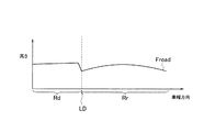
段差判定位置回路15は、演算回路14により取得された路面の高さから、段差判定位置(Pa)における路面の測定点の高さデータ分布(測距データ)を算出する。図4の縦軸は路面(Froad)の高さを示し、横軸は車幅方向に延びる段差判定位置(Pa)を示す。
The step
図4に示すように、車道(Rr)と段差部(Rd)との境界には、段差(LD)が形成されている。車道(Rr)の路面(Froad)には、その高さが中央部から両端部である路肩に向けて低くなる傾斜(カント)が設けられている。これは、車道の水捌けを良くして車道に水が溜まらない一般的な道路設計及び構造である。段差(LD)において、路面(Froad)は急激に高くなり、段差部(Rd)の路面(Froad)は、車道(Rr)よりも一段高い平坦な面を形成している。例えば、歩道などが設けられている。 As shown in FIG. 4, a step (LD) is formed at the boundary between the roadway (Rr) and the step portion (Rd). The road surface (Froad) of the roadway (Rr) is provided with a slope (cant) whose height decreases from the center toward the road shoulder at both ends. This is a general road design and structure that improves the drainage of the roadway and does not collect water on the roadway. In the level difference (LD), the road surface (Froad) increases rapidly, and the road surface (Froad) of the level difference portion (Rd) forms a flat surface that is one step higher than the roadway (Rr). For example, a sidewalk is provided.
段差検出回路18は、段差判定位置(Pa)における路面(Froad)の高さ変化に基づいて、路面上の段差(LD)を検出する。段差検出回路18は、図4に示す段差判定位置(Pa)における路面の高さ分布(測距データ)を用いて、路面(Froad)の高さ変化を判断することができる。
The level
段差(LD)の検出方法の一例を説明する。段差判定位置(Pa)上に走行可能領域を設定し、走行可能領域において、路面(Froad)の傾斜を曲線で近似する。走行可能領域とは、車両(Vc)が走行することが可能な領域であって、車道の境界、例えば、段差を含まない領域を示す。そして、段差判定位置(Pa)において、走行可能領域に隣接する道路境界検出領域(Hg)を設定する。近似曲線と道路境界検出領域(Hg)における路面(Froad)の高さとを比較する。近似曲線と路面(Froad)の高さとの差が、一般的な縁石高さである0.1m以上となる箇所に、段差があると判断する。道路境界検出領域(Hg)については、図6及び図7を参照して後述する。 An example of a method for detecting a level difference (LD) will be described. A travelable area is set on the step determination position (Pa), and the slope of the road surface (Froad) is approximated by a curve in the travelable area. The travelable region is a region where the vehicle (Vc) can travel and indicates a boundary of the roadway, for example, a region not including a step. Then, a road boundary detection area (Hg) adjacent to the travelable area is set at the step determination position (Pa). The approximate curve is compared with the height of the road surface (Froad) in the road boundary detection region (Hg). It is determined that there is a step at a location where the difference between the approximate curve and the road surface (Froad) is 0.1 m or more, which is a general curb height. The road boundary detection area (Hg) will be described later with reference to FIGS.
なお、具体的な段差(LD)の検出方法は、上記方法に限らない。既知のいずれの方法、例えば、特開2014−002608号公報に開示されている方法を用いても構わない。 A specific method for detecting the level difference (LD) is not limited to the above method. Any known method, for example, a method disclosed in Japanese Patent Application Laid-Open No. 2014-002608 may be used.
段差検出回路18は、路面(Froad)の車幅方向の段差判定位置(Pa)上の所定範囲において段差の検出を試みる。所定範囲において段差が検出されなかった場合、段差の検出を断念しても構わない。
The
図6及び図7を参照して、路面(Froad)の車幅方向の段差判定位置(Pa)上の所定範囲について説明する。図6は、所定範囲の一例として、道路境界検出領域(Hg)を示す上面図である。段差検出回路18は、先ず、段差判定位置(Pa)における車両(Vc)の進行方向の走行可能領域(G1)を推定する。走行可能領域(G1)とは、車両(Vc)が走行することが可能な領域であって、車道の境界、例えば、段差を含まない領域を示す。段差検出回路18は、図6に示すように、車両(Vc)の幅(Wvc)に対して所定の走行余裕領域を付加した領域を、車両(Vc)の進行方向の走行可能領域(G1)として推定する。例えば、走行余裕領域として、実際の道路境界を含まないように、0.1m〜0.5mに設定する。なお、Cvcは、車両(Vc)の車幅方向の中心軸を示している。
With reference to FIG.6 and FIG.7, the predetermined range on the level | step difference determination position (Pa) of the vehicle width direction of a road surface (Froad) is demonstrated. FIG. 6 is a top view showing a road boundary detection region (Hg) as an example of the predetermined range. The
道路境界検出領域(Hg)は、走行可能領域(G1)の端部から車幅方向に所定距離までの領域である。所定距離としては、例えば、測距センサ12の有効検出距離(10m)以内で道路端(BON)が含まれる領域で設定すればよい。
The road boundary detection region (Hg) is a region from the end of the travelable region (G 1 ) to a predetermined distance in the vehicle width direction. For example, the predetermined distance may be set in an area including the road edge (B ON ) within the effective detection distance (10 m) of the
図7は、所定範囲の他の例として、道路境界検出領域(Hg’)を示す上面図である。道路境界検出領域(Hg’)を、過去の処理サイクルで検出された段差の位置(PB1、PB2、・・・)に基づいて設定することもできる。例えば、前回の段差の位置(PB1)から車幅方向に一定の余裕距離(PLA)だけ延長した領域を、今回の道路境界検出領域(Hg’)とすることができる。もちろん、道路境界検出領域(Hg’)の始点は、走行可能領域(G1)の端部である。走行可能領域(G1)の定義は図6と同じである。 FIG. 7 is a top view showing a road boundary detection region (Hg ′) as another example of the predetermined range. The road boundary detection area (Hg ′) can also be set based on the step positions (P B1 , P B2 ,...) Detected in the past processing cycle. For example, the current road boundary detection region (Hg ′) may be a region extended from the previous step position (P B1 ) by a certain margin distance (P LA ) in the vehicle width direction. Of course, the starting point of the road boundary detection area (Hg ′) is the end of the travelable area (G 1 ). The definition of the travelable area (G 1 ) is the same as in FIG.
スロープ境界検出回路19は、路面(Froad)の車幅方向の段差判定位置(Pa)上の所定範囲において段差が検出されなかった場合、路面(Froad)の車幅方向の勾配に基づいて、スロープと車道との境界を検出する。車両が車道から敷地へ進入可能な場所には、図4の段差(LD)の代わりに、図5に示すように、スロープが形成されている。スロープと車道(Rr)との境界では、不連続な路面(Froad)の勾配変化が形成されている。例えば、図5に示すように、車道(Rr)の勾配の符号とスロープの勾配の符号が異なる。
When no step is detected in a predetermined range on the step determination position (Pa) in the vehicle width direction on the road surface (Froad), the slope
例えば、スロープ境界検出回路19は、道路境界検出領域(Hg)の両端(DBA、DFR)から路面(Froad)の車幅方向の勾配をそれぞれ走査し、勾配が交差する位置から、スロープと車道との境界の位置を検出することができる。具体的には、先ず、道路境界検出領域(Hg)を複数の区分(Kd1〜Kd7)に分割し、区分(Kd1〜Kd7)毎に路面の車幅方向の勾配を検出する。道路境界検出領域(Hg)の両端(DBA、DFR)から、各区分(Kd1〜Kd7)の勾配を走査する。スロープ境界検出回路19は、路面(Froad)の車幅方向の勾配が基準値よりも大きく変化する区分(Kd3)をスロープと車道との境界として検出することができる。基準値の一例は10度である。或いは、スロープ境界検出回路19は、図5に示すように、路面(Froad)の車幅方向の勾配の符号が反転する箇所をスロープと車道との境界として検出してもよい。
For example, the slope
道路境界推定回路20は、スロープと車道(Rr)との境界或いは段差(LD)を道路境界と推定する。道路境界推定回路20は、路面(Froad)の車幅方向の段差判定位置(Pa)上の所定範囲において段差が検出されれば、段差(LD)を道路境界と推定する。段差が検出されず、且つ、スロープと車道との境界が検出された場合、道路境界推定回路20は、スロープと車道との境界を道路境界と推定する。
The road
図8を参照して、図1の道路境界検出装置1を用いた道路境界検出方法の一例を説明する。
With reference to FIG. 8, an example of a road boundary detection method using the road
まず、ステップS01で、測距センサ12の一例であるステレオカメラを用いて、ステレオ画像を取得する。ステップS03に進み、演算回路14は、ステレオ画像に対してレンズの歪みを補正するレンズ歪み補正処理を行い、ステレオ画像間の上下位置を補正する平行化補正処理を行う。ステップS05に進み、演算回路14は、ステレオ画像間の各画素の対応付けを推定するステレオマッチング処理を行う。これにより、車両周囲にある物体までの距離及び方位を検出することができる。更に、演算回路14は、座標変換処理を施すことにより、測距データの座標上の車両の周囲における路面の三次元情報を取得することができる。
First, in step S01, a stereo image is acquired using a stereo camera which is an example of the
ステップS07に進み、段差判定位置回路15は、例えば図2及び図3に示すように、測距センサ12で検出された測距データの座標上の車両の周囲の路面に車幅方向の線状の段差判定位置(Pa)を設定する。そして、段差判定位置回路15は、演算回路14により取得された路面の三次元情報から、図4に示すように、段差判定位置(Pa)における路面の高さ分布(測距データ)を算出する。
Proceeding to step S07, the step determining
ステップS09に進み、段差検出回路18は、図6或いは図7に示したように、路面(Froad)の車幅方向の段差判定位置(Pa)上の道路境界検出領域(Hg、Hg’)において、段差(LD)の検出を試みる。段差(LD)が検出された場合(ステップS11でYES)、ステップS13を実施せずに、ステップS15へ進み、段差(LD)が検出されなかった場合(ステップS11でNO)、ステップS13へ進む。
Proceeding to step S09, as shown in FIG. 6 or FIG. 7, the level
ステップS13において、スロープ境界検出回路19は、路面(Froad)の車幅方向の勾配に基づいて、スロープと車道との境界を検出する。ステップS15において、道路境界推定回路20は、スロープと車道U(Rr)との境界或いは段差(LD)を道路境界と推定する。段差(LD)が検出された場合(ステップS11でYES)、段差(LD)を道路境界と推定する。一方、ステップS13でスロープと車道との境界が検出された場合、スロープと車道との境界を道路境界と推定する。
In step S13, the slope
図9を参照して、スロープ境界検出回路19が実施する図8のステップS13の詳細な手順の一例を説明する。
With reference to FIG. 9, an example of the detailed procedure of step S13 of FIG. 8 performed by the slope
先ず、路面(Froad)の車幅方向の道路境界検出領域(Hg)を複数の区分(Kd1〜Kd7)に分割する(S301)。ステップS303で、区分(Kd1〜Kd7)毎に路面の勾配を算出する。ステップS305で、路面(Froad)の車幅方向の道路境界検出領域(Hg)の両端(DBA、DFR)から、各区分(Kd1〜Kd7)の勾配を走査する。ステップS307で、路面(Froad)の車幅方向の勾配の符号が反転する箇所があるか否かを判断する。反転する箇所があれば(S307でYES)、当該箇所を、スロープと車道との境界として検出する(S309)。反転する箇所がなければ(S307でNO)、スロープと車道との境界の検出を断念する(S311)。このように、スロープ境界検出回路19は、勾配の符号変化から、スロープと車道との境界の位置を検出することができる。
First, the road boundary detection region (Hg) in the vehicle width direction of the road surface (Froad) is divided into a plurality of sections (K d1 to K d7 ) (S301). In step S303, the gradient of the road surface is calculated for each section (K d1 to K d7 ). In step S305, the gradient of each section (K d1 to K d7 ) is scanned from both ends (D BA , D FR ) of the road boundary detection region (Hg) in the vehicle width direction of the road surface (Froad). In step S307, it is determined whether or not there is a portion where the sign of the gradient in the vehicle width direction of the road surface (Froad) is reversed. If there is a part to be reversed (YES in S307), the part is detected as a boundary between the slope and the roadway (S309). If there is no portion to be reversed (NO in S307), the detection of the boundary between the slope and the roadway is abandoned (S311). As described above, the slope
図10を参照して、図8のステップS13の詳細な手順の他の例を説明する。図9と比べて、S301、S303、S309、S311は同じであるが、S307の代わりにS308を実施し、図9のS305は実施しない。 With reference to FIG. 10, another example of the detailed procedure of step S13 in FIG. 8 will be described. Compared to FIG. 9, S301, S303, S309, and S311 are the same, but S308 is performed instead of S307, and S305 of FIG. 9 is not performed.
ステップS308において、スロープ境界検出回路19は、道路境界検出領域(Hg)のいずれか一方の端(DBA、DFR)から、各区分(Kd1〜Kd7)の勾配を走査する。そして、路面(Froad)の車幅方向の勾配が基準値(例えば、10度)よりも大きく変化する区分があるか否かを判断する。基準値よりも大きく変化する区分があれば、ステップS309へ進み、基準値よりも大きく変化する区分がなければ、ステップS311へ進む。
In step S308, the slope
道路境界検出装置1は、図8に示す一連の処理サイクルを所定の周期のもとで繰り返し実施することにより、連続して道路境界を検出する。検出される道路境界の位置は、車両(Vc)を基準とする相対的な位置である。検出される道路境界の情報には、前回の検出時から今回の検出時までの車両の挙動情報が関連づけられて、メモリに記憶される。よって、道路境界検出装置1は、車両の挙動情報から車両の移動距離及び移動方向を算出することにより、繰り返し検出される道路境界の軌跡を求めることができる。なお、車両の挙動情報は、既知の方法から求めることができる。例えば、ステレオカメラによるビジュアルオドメトリ情報や、車速情報と車両のヨーレート情報との組合せ、或いはGPS(衛星測位システム)による自己位置情報を用いることができる。
The road
なお、図8のフローチャートにおいて、スロープ境界検出回路19は、車両が走行する一定区間において、路面上の段差(LD)が検出されなかった場合に、ステップ13へ進み、スロープと車道との境界を検出してもよい。実際には途切れること無く連続する段差(LD)が形成されている道路を車両が走行していても、ノイズによって段差(LD)が検出されない処理サイクルが含まれる場合がある。或いは、連続する段差(LD)の一部だけが崩れているため、段差(LD)が検出されない処理サイクルが含まれる場合もある。
In the flowchart of FIG. 8, the slope
このように、ノイズや段差の一部崩壊によってステップS13が安易に実行されてしまうと、処理遅延が生じ、また道路境界検出装置1の動作自体も不安定になってしまう。そこで、段差検出回路18は、車両が走行する一定区間において、路面上の段差(LD)が連続して検出されなかった場合に限り、段差が検出されなかったと判断する(ステップS11でNO)。段差が検出されない処理サイクルがあっても、車両が一定区間を走行するまで当該サイクルが繰り返されない限りは、段差が検出されなかったは判断しない(ステップS11でYES)。これにより、道路境界検出装置1の効率的な動作が実現される。なお、車両が走行する一定区間としては、連続して3回のサイクルで段差非検出であった場合が例示される。
As described above, if Step S13 is easily executed due to noise or partial collapse of the level difference, a processing delay occurs, and the operation of the road
以上説明したように、第1実施形態によれば、以下の作用効果が得られる。 As described above, according to the first embodiment, the following operational effects can be obtained.
路面(Froad)の車幅方向の道路境界検出領域(Hg)において段差(LD)が検出されなかった場合、路面(Froad)の車幅方向の勾配に基づいて、スロープと車道との境界を検出し、スロープと車道との境界を道路境界と推定する。これにより、段差(LD)の代わりにスロープが設けられた場所において、スロープを超えた先にある段差ではなく、スロープと車道との境界を道路境界として検出することができる。よって、道路境界を精度良く検出することができる。 When no step (LD) is detected in the road boundary detection region (Hg) in the vehicle width direction of the road surface (Froad), the boundary between the slope and the roadway is detected based on the gradient in the vehicle width direction of the road surface (Froad). Then, the boundary between the slope and the road is estimated as the road boundary. As a result, in the place where the slope is provided instead of the step (LD), the boundary between the slope and the roadway can be detected as the road boundary instead of the step beyond the slope. Therefore, the road boundary can be detected with high accuracy.
スロープ境界検出回路19は、道路境界検出領域(Hg)の両端(DBA、DFR)から路面(Froad)の車幅方向の勾配をそれぞれ走査し、勾配が交差する位置から、スロープと車道との境界の位置を検出する。これにより、路面(Froad)の車幅方向の勾配が交差する位置で、路面(Froad)の車幅方向の勾配が大きく変化するので、この交差位置から、スロープと車道との境界の位置を精度良く検出することができる。
The slope
段差検出回路18は、路面上の段差(LD)の位置を繰り返し検出する。スロープ境界検出回路19は、前回検出した路面上の段差(LD)の位置に基づいて、道路境界検出領域(Hg)を設定する。これにより、道路境界が検出される領域を予め絞り込むことができるので、道路境界の検出に要する時間を短縮し、計算負荷を軽減することができる。
The level
スロープ境界検出回路19は、車両が走行する一定区間において、路面上の段差(LD)が検出されなかった場合に、スロープと車道との境界を検出する(S13)。例えば、ノイズや段差の一部崩壊により一定区間に達しない短い区間のみ段差が非検出となっても、スロープ境界の検出処理(S13)は開始されない。スロープ境界の検出処理フローが頻発することが抑制され、システムの安定性が向上する。
The slope
スロープ境界検出回路19は、道路境界検出領域(Hg)において、路面の車幅方向の勾配が基準値よりも大きく変化する箇所をスロープと車道との境界として検出する。これにより、一般的なスロープの傾斜角度及び車道の傾斜角度を考慮して基準値を設定できるので、スロープと車道との境界を精度良く検出することができる。
In the road boundary detection area (Hg), the slope
スロープ境界検出回路19は、道路境界検出領域(Hg)において、路面の車幅方向の勾配の符号が反転する箇所をスロープと車道との境界として検出する。一般的なスロープの傾斜及び車道の傾斜は逆向きであるため、スロープと車道との境界を精度良く検出することができる。
The slope
(第1変形例)
測距センサ12としてのステレオカメラを、車両(Vc)の前部ではなく、図11に示すように、車両(Vc)の側部に設置し、ステレオカメラの撮像範囲を車両(Vc)の側方としても構わない。この場合も、車両(Vc)の進行方向を第1の所定方向(Da)とする。これにより、段差判定位置回路15は、車両の周囲(側方)の路面に、段差(LD)と交わる線状の段差判定位置(Pa)を設定することができる。具体的には、測距センサ12から第1の所定方向(Da)に所定距離だけ離れ、第1の所定方向(Da)に直交する方向に延びる段差判定位置(Pa)を設定することができる。
(First modification)
As shown in FIG. 11, the stereo camera as the
(第2変形例)
測距センサ12の他の例として、レーザレンジファインダ(LRF)がある。LRFは、車両周囲の物体に向けてレーザーを照射し、物体に反射して戻ってきたレーザーを観測する。そして、LRFは、レーザーの照射方向に基づいて物体が位置する方位を計測すると共に、レーザーの照射から反射レーザーの観測までの時間に基づいて物体までの距離を計測する。LRFは、レーザースキャナとも呼ばれる。LRFの照射範囲は任意に設定可能である。図12は、車両(Vc)のルーフ中央部にLRF(12)を設定し、周囲全体を照射範囲とする360度LRFの例を示す。段差判定位置回路15は、測距センサ12から第1の所定方向(Da)に所定距離だけ離れ、第1の所定方向(Da)に直交する方向に延びる段差判定位置(Pa)を設定する。よって、車両(Vc)の前部に測距センサ12を設置した図2の例と同様にして、車両(Vc)の進行方向を第1の所定方向(Da)とするので、車幅方向に延びる段差判定位置(Pa)が、車両(Vc)の前方に設定される。
(Second modification)
Another example of the
なお、俯角を付けてLRFを搭載することで走行中に車両進行方向を広範囲にわたって調査することが可能となる。また、複数のレーザーを同時に照射可能なマルチレイヤー型のLRFを用いることも可能である。 In addition, it becomes possible to investigate the vehicle traveling direction over a wide range during traveling by mounting the LRF with a depression angle. It is also possible to use a multi-layer LRF capable of simultaneously irradiating a plurality of lasers.
測距センサ12としてレーザレンジファインダ(LRF)を用いた場合の段差検出方法は、図8のS01〜S05の代わりに、図13に示すステップS21及びS23を実施する点が相違する。その他のステップS07〜S13は、図8と同じであり、説明を省略する。
The step detection method when a laser range finder (LRF) is used as the
ステップS21において、LRF(12)は、レーザーが照射された物体の方位と共に、物体までの距離を計測する。計測データは演算回路14に送信される。ステップS23に進み、演算回路14は、LRF(12)を原点とした極座標系の計測データを、車両(Vc)を原点とした直交座標系に変換する。これにより、演算回路14は、車両の周囲における路面の三次元情報を取得することができる。その後、ステップS07へ進む。
In step S21, the LRF (12) measures the distance to the object together with the direction of the object irradiated with the laser. The measurement data is transmitted to the
(第2実施形態)
図14を参照して、第2実施形態に係わる自己位置推定装置2の全体構成を説明する。自己位置推定装置2は、第1実施形態の道路境界検出装置1により検出された道路境界と、地図情報に含まれる道路境界を示す情報とを照合することにより、車両(Vc)の地図上の位置を推定する。
(Second Embodiment)
With reference to FIG. 14, the whole structure of the self-
具体的に、自己位置推定装置2は、測距センサ12と、測距センサ12による測定データから自己位置を推定する一連の情報処理を実行するマイクロコンピュータ13と、道路境界を示す情報を含む地図情報を記憶する地図データベース23とを備える。マイクロコンピュータ13は、予めインストールされたコンピュータプログラムを実行することにより、図1に示す情報処理回路(14、15、18、19、20)の他に、地図情報取得回路21と、自己位置推定回路22とを更に構成する。
Specifically, the self-
地図情報取得回路21は、車両周囲の地図情報を地図データベース23から取得する。自己位置推定回路22は、地図情報に含まれる道路境界を示す情報と、道路境界推定回路20により推定された道路境界とを照合することにより、車両(Vc)の地図上の位置を推定する。
The map
道路境界推定回路20は、路面の車幅方向の段差判定位置(Pa)上の所定範囲外で段差(LD)が検出され、且つスロープと車道との境界が検出されなかった場合、所定範囲外で検出された段差を、道路境界の推定に含めない。
The road
具体的に、段差検出回路18が、図6又は図7に示した道路境界検出領域(Hg、Hg’)の中で段差(LD)を検出できず、道路境界検出領域(Hg、Hg’)外で段差(LD)を検出した。そして、スロープ境界検出回路19がスロープと車道との境界を検出しなかった。この場合、道路境界推定回路20は、道路境界検出領域(Hg、Hg’)外の段差(LD)を、道路境界として推定しない。これにより、スロープを越えて先にある段差を誤って道路境界として推定することが抑制され、道路境界の検出精度が向上する。
Specifically, the level
上記のように、本発明の実施形態を記載したが、この開示の一部をなす論述及び図面はこの発明を限定するものであると理解すべきではない。この開示から当業者には様々な代替実施の形態、実施例及び運用技術が明らかとなろう。 Although the embodiments of the present invention have been described as described above, it should not be understood that the descriptions and drawings constituting a part of this disclosure limit the present invention. From this disclosure, various alternative embodiments, examples and operational techniques will be apparent to those skilled in the art.
1 道路境界検出装置
2 自己位置推定装置
11 測距部
12 測距センサ
13 マイクロコンピュータ
14 演算回路
15 段差判定位置回路
18 段差検出回路
19 スロープ境界検出回路
20 道路境界推定回路
21 地図情報取得回路
22 自己位置推定回路
23 地図データベース
G1 走行可能領域
Froad 路面
Hg 道路境界検出領域(所定範囲)
Pa 段差判定位置
LD 段差
Vc 車両
DESCRIPTION OF
Pa Step judgment position LD Step Vc Vehicle
Claims (8)
前記路面の高さ変化に基づいて、路面上の段差を検出する段差検出回路と、
前記路面の車幅方向の所定範囲において前記段差が検出されなかった場合、路面の車幅方向の勾配に基づいて、スロープと車道との境界を検出するスロープ境界検出回路と、
前記スロープと車道との境界或いは前記段差を道路境界と推定する道路境界推定回路と、
を備えることを特徴とする道路境界検出装置。 A distance measuring unit for detecting the height of the road surface around the vehicle;
A step detecting circuit for detecting a step on the road surface based on a change in the height of the road surface;
A slope boundary detection circuit for detecting a boundary between a slope and a roadway based on a gradient in the vehicle width direction of the road surface when the step is not detected in a predetermined range in the vehicle width direction of the road surface;
A road boundary estimation circuit for estimating a boundary between the slope and the roadway or the step as a road boundary;
A road boundary detection apparatus comprising:
前記スロープ境界検出回路は、前回検出した前記路面上の段差の位置に基づいて、前記所定範囲を設定する
ことを特徴とする請求項1又は2に記載の道路境界検出装置。 The step detection circuit repeatedly detects the position of the step on the road surface,
The road boundary detection device according to claim 1, wherein the slope boundary detection circuit sets the predetermined range based on a position of a step on the road surface detected last time.
車両周囲の地図情報を取得する地図情報取得回路と、
前記地図情報に含まれる前記道路境界を示す情報と、前記道路境界推定回路により推定された前記道路境界とを照合することにより、前記車両の地図上の位置を推定する自己位置推定回路と、を備え、
前記道路境界推定回路は、前記路面の車幅方向の所定範囲外で前記段差が検出され、且つ前記スロープと前記車道との境界が検出されなかった場合、前記所定範囲外で検出された前記段差を、前記道路境界の推定に含めない
ことを特徴とする自己位置推定装置。 The road boundary detection device according to any one of claims 1 to 6,
A map information acquisition circuit for acquiring map information around the vehicle;
A self-position estimation circuit that estimates the position of the vehicle on the map by comparing information indicating the road boundary included in the map information with the road boundary estimated by the road boundary estimation circuit; Prepared,
The road boundary estimation circuit detects the step detected outside the predetermined range when the step is detected outside the predetermined range in the vehicle width direction of the road surface and the boundary between the slope and the roadway is not detected. Is not included in the estimation of the road boundary.
前記路面の高さ変化に基づいて、路面上の段差を検出し、
前記路面の車幅方向上の所定範囲において前記段差が検出されなかった場合、路面の車幅方向の勾配に基づいて、スロープと車道との境界を検出し、
前記スロープと車道との境界或いは前記段差を道路境界と推定する
ことを特徴とする道路境界検出方法。 Detect the road surface height around the vehicle,
Based on the change in the height of the road surface, a step on the road surface is detected,
When the step is not detected in a predetermined range in the vehicle width direction of the road surface, based on the gradient of the road surface in the vehicle width direction, the boundary between the slope and the roadway is detected,
A road boundary detection method, wherein a boundary between the slope and a roadway or the step is estimated as a road boundary.
Priority Applications (1)
| Application Number | Priority Date | Filing Date | Title |
|---|---|---|---|
| JP2015153852A JP6477340B2 (en) | 2015-08-04 | 2015-08-04 | Road boundary detection device, self-position estimation device, and road boundary detection method |
Applications Claiming Priority (1)
| Application Number | Priority Date | Filing Date | Title |
|---|---|---|---|
| JP2015153852A JP6477340B2 (en) | 2015-08-04 | 2015-08-04 | Road boundary detection device, self-position estimation device, and road boundary detection method |
Publications (2)
| Publication Number | Publication Date |
|---|---|
| JP2017033366A JP2017033366A (en) | 2017-02-09 |
| JP6477340B2 true JP6477340B2 (en) | 2019-03-06 |
Family
ID=57986268
Family Applications (1)
| Application Number | Title | Priority Date | Filing Date |
|---|---|---|---|
| JP2015153852A Active JP6477340B2 (en) | 2015-08-04 | 2015-08-04 | Road boundary detection device, self-position estimation device, and road boundary detection method |
Country Status (1)
| Country | Link |
|---|---|
| JP (1) | JP6477340B2 (en) |
Families Citing this family (3)
| Publication number | Priority date | Publication date | Assignee | Title |
|---|---|---|---|---|
| US11151395B2 (en) | 2017-08-07 | 2021-10-19 | Hitachi Astemo, Ltd. | Roadside object detection device, roadside object detection method, and roadside object detection system |
| JP7414603B2 (en) * | 2020-03-19 | 2024-01-16 | トヨタ自動車株式会社 | Track boundary determination device and track boundary determination method |
| CN114250676A (en) * | 2021-12-28 | 2022-03-29 | 云南省公路科学技术研究院 | Device for rapidly detecting cross slope of asphalt pavement and using method thereof |
Family Cites Families (6)
| Publication number | Priority date | Publication date | Assignee | Title |
|---|---|---|---|---|
| JP3372190B2 (en) * | 1997-07-17 | 2003-01-27 | 富士重工業株式会社 | Vehicle collision prevention device |
| JP2001331787A (en) * | 2000-05-19 | 2001-11-30 | Toyota Central Res & Dev Lab Inc | Road shape estimating device |
| JP4425810B2 (en) * | 2005-02-09 | 2010-03-03 | アイシン・エィ・ダブリュ株式会社 | Step learning system |
| JP5605289B2 (en) * | 2011-04-05 | 2014-10-15 | トヨタ自動車株式会社 | Fault recognition method and fault recognition system for moving body |
| JP2013205130A (en) * | 2012-03-28 | 2013-10-07 | Zenrin Co Ltd | Method for generating road surface shape data, device for generating road surface shape data and computer program |
| JP5829980B2 (en) * | 2012-06-19 | 2015-12-09 | トヨタ自動車株式会社 | Roadside detection device |
-
2015
- 2015-08-04 JP JP2015153852A patent/JP6477340B2/en active Active
Also Published As
| Publication number | Publication date |
|---|---|
| JP2017033366A (en) | 2017-02-09 |
Similar Documents
| Publication | Publication Date | Title |
|---|---|---|
| US11763571B2 (en) | Monocular cued detection of three-dimensional structures from depth images | |
| US9771080B2 (en) | Road surface gradient detection device | |
| US10482615B2 (en) | Image processing device and image processing method | |
| US9898669B2 (en) | Traveling road surface detection device and traveling road surface detection method | |
| JP6561670B2 (en) | Step detecting device and step detecting method | |
| JP6451858B2 (en) | Step detecting device and step detecting method | |
| JP2016200557A (en) | Calibration device, distance measurement apparatus and calibration method | |
| JP2012159469A (en) | Vehicle image recognition device | |
| JP6477340B2 (en) | Road boundary detection device, self-position estimation device, and road boundary detection method | |
| US20200193184A1 (en) | Image processing device and image processing method | |
| JP6493533B2 (en) | Step detecting device and step detecting method | |
| JP6485280B2 (en) | Step detecting device and step detecting method | |
| JP6451544B2 (en) | Road boundary detection device, self-position estimation device, and road boundary detection method | |
| JP2023061621A (en) | Image processing device | |
| JP2020095625A (en) | Image processing device and image processing method |
Legal Events
| Date | Code | Title | Description |
|---|---|---|---|
| A621 | Written request for application examination |
Free format text: JAPANESE INTERMEDIATE CODE: A621 Effective date: 20180126 |
|
| A977 | Report on retrieval |
Free format text: JAPANESE INTERMEDIATE CODE: A971007 Effective date: 20181220 |
|
| TRDD | Decision of grant or rejection written | ||
| A01 | Written decision to grant a patent or to grant a registration (utility model) |
Free format text: JAPANESE INTERMEDIATE CODE: A01 Effective date: 20190108 |
|
| A61 | First payment of annual fees (during grant procedure) |
Free format text: JAPANESE INTERMEDIATE CODE: A61 Effective date: 20190121 |
|
| R151 | Written notification of patent or utility model registration |
Ref document number: 6477340 Country of ref document: JP Free format text: JAPANESE INTERMEDIATE CODE: R151 |