JP6474262B2 - Trunnion type ball valve - Google Patents
Trunnion type ball valve Download PDFInfo
- Publication number
- JP6474262B2 JP6474262B2 JP2015014295A JP2015014295A JP6474262B2 JP 6474262 B2 JP6474262 B2 JP 6474262B2 JP 2015014295 A JP2015014295 A JP 2015014295A JP 2015014295 A JP2015014295 A JP 2015014295A JP 6474262 B2 JP6474262 B2 JP 6474262B2
- Authority
- JP
- Japan
- Prior art keywords
- ball
- seat
- ball seat
- seal
- trunnion
- Prior art date
- Legal status (The legal status is an assumption and is not a legal conclusion. Google has not performed a legal analysis and makes no representation as to the accuracy of the status listed.)
- Active
Links
- 238000007789 sealing Methods 0.000 claims description 61
- 239000012530 fluid Substances 0.000 claims description 29
- 230000002093 peripheral effect Effects 0.000 claims description 22
- 238000011144 upstream manufacturing Methods 0.000 claims description 11
- 230000002159 abnormal effect Effects 0.000 description 5
- 239000000463 material Substances 0.000 description 4
- 229920001343 polytetrafluoroethylene Polymers 0.000 description 3
- 239000004810 polytetrafluoroethylene Substances 0.000 description 3
- 239000011347 resin Substances 0.000 description 3
- 229920005989 resin Polymers 0.000 description 3
- 239000010935 stainless steel Substances 0.000 description 3
- 229910001220 stainless steel Inorganic materials 0.000 description 3
- 229910000975 Carbon steel Inorganic materials 0.000 description 2
- 239000004696 Poly ether ether ketone Substances 0.000 description 2
- 239000010962 carbon steel Substances 0.000 description 2
- 230000005489 elastic deformation Effects 0.000 description 2
- 230000009191 jumping Effects 0.000 description 2
- 229920002530 polyetherether ketone Polymers 0.000 description 2
- 239000004677 Nylon Substances 0.000 description 1
- 238000013459 approach Methods 0.000 description 1
- 230000006866 deterioration Effects 0.000 description 1
- 230000007613 environmental effect Effects 0.000 description 1
- 239000007769 metal material Substances 0.000 description 1
- 229920001778 nylon Polymers 0.000 description 1
- 238000012856 packing Methods 0.000 description 1
- -1 polytetrafluoroethylene Polymers 0.000 description 1
- 230000000452 restraining effect Effects 0.000 description 1
Images


Description
本発明はトラニオン型ボールバルブに関し、特に大口径で高圧が加わる場合にも高シール性を維持できるトラニオン型ボールバルブに関する。 The present invention relates to a trunnion-type ball valve, and more particularly to a trunnion-type ball valve that can maintain high sealing performance even when high pressure is applied with a large diameter.
トラニオン型ボールバルブは、特に高圧流体に適したバルブとして知られ、通常、弁座となるボールシートがシートリテーナに保持された状態でボデーに装着され、ボールシートがコイルスプリングの弾発力によって弁体方向に弾発されてボールに押し付けられることにより、一次側(上流側)ボールシートで流体が封止される構造に設けられている。
この種のトラニオン型バルブとして、例えば、特許文献1のボール弁が開示されている。このボール弁では、ボールシートがシートリテーナに固定されてボールシートの脱落が防がれた構造に設けられている。
図5に示したボールバルブ1においては、シートリテーナ2からボールシート3の脱落が防止された状態で、かつボールシート3がシートリテーナ2に対してフリーな状態で装着された構造になっている。
A trunnion type ball valve is known as a valve particularly suitable for a high-pressure fluid, and is usually mounted on a body with a ball seat as a valve seat held by a seat retainer, and the ball seat is valved by the elasticity of a coil spring. It is provided in a structure in which fluid is sealed with a primary (upstream) ball sheet by being ejected in the body direction and pressed against the ball.
As this type of trunnion type valve, for example, a ball valve disclosed in Patent Document 1 is disclosed. This ball valve has a structure in which the ball seat is fixed to the seat retainer to prevent the ball seat from falling off.
The ball valve 1 shown in FIG. 5 has a structure in which the
上記の何れの構造のボールバルブの場合にも、高シール性を維持しながら閉止できるボールシートと弁体との接触状態であることが要求される。
特許文献1のボール弁では、ボールシートのシール面が弁体のシール面と同じ曲率に設けられ、これら同じ曲率のボールシートと弁体とのシール面同士が全周にわたって密着することでシール性を確保しようとしている。図5のボールバルブにおいても、特許文献1と同様に、ボールシート3に形成される一次側シール部4から二次側シール部5までの範囲のシール面6が、ボール弁体7外周の弁体シール面8と同じ曲率に設けられている。
すなわち、これらのボールバルブでは、図5において、ボール弁体7の球形とボールシート3のシール面6との形状が同一寸法に設けられ、低圧時から高圧時までにおいて、弁体シール面8にシール面6が一次側シール部4から二次側シール部5までの範囲において常に面接触した状態で流体圧力が封止されるようになっている。
In the case of any of the above-described ball valves, it is required that the ball seat is in contact with the valve body that can be closed while maintaining high sealing performance.
In the ball valve of Patent Document 1, the sealing surface of the ball seat is provided with the same curvature as the sealing surface of the valve body, and the sealing surfaces of the ball seat and the valve body having the same curvature adhere to each other over the entire circumference. Trying to secure. Also in the ball valve of FIG. 5, as in Patent Document 1, the
That is, in these ball valves, in FIG. 5, the spherical shape of the
一方、特許文献2においては、シート保持部にボールシートが周方向に回転可能な状態で保持され、ボールの回転に伴って周方向に回転することによりボールシートの偏摩耗を防止してシール性の低下を防止しようとするボールバルブが開示されている。
特許文献3のボールバルブにおいては、シートリングの底面と、シート保持手段のシートリング保持溝の底面との空間が外径になるほどボール側に傾斜しながら広くなるように設けられ、シートリングに押圧力が加わったときの押圧変形が空間に吸収されることにより、シール部の位置が変わることを防いでシール性を保持しようとするものである。
上述したトラニオン型ボールバルブにおいて、一般的に流体温度が常温から250℃程度までの温度では、ボールシートとして樹脂材料が使用される。この場合、流体圧力が高温になるとボールシートはその圧力に応じて弾性変形を生じながら流体をシールすることになる。
On the other hand, in
In the ball valve of
In the above-described trunnion type ball valve, a resin material is generally used as a ball sheet at a fluid temperature ranging from room temperature to about 250 ° C. In this case, when the fluid pressure becomes high, the ball seat seals the fluid while elastically deforming according to the pressure.
前述の特許文献1や図5の構造のボール弁では、組立後及び低圧時の状態で流路側から高圧が加わった場合、図6の矢印に示すように樹脂製のボールシート3がシートリテーナ2との当接部9を中心に外側に開く方向に弾性変形する。このようにボールシート3が弾性変形したときに、当接部9が一次側シール部4よりも図5において外径側にあるため、この一次側シール部4が当接部9を中心としたボールシート3の外側に開く回転作用によりボール弁体7に近づく方向に移動する。その結果、図6に示すように、ボール弁体7とボールシート3とのシールが一次側シール部4から二次側シール部5までの面接触から一次側シール部4側の線接触に変化し、この線接触のシールにより一次側シール部4のシール面圧が局部的に上昇し、ボールシート3が部分的に変形するおそれがある。この状態でバルブを回転操作すると、一次側シール部4が面圧に耐えきれずに偏摩耗を生じて流体の漏洩につながりやすくなる。
In the ball valve having the structure of Patent Document 1 and FIG. 5 described above, when a high pressure is applied from the flow path side after assembly and at a low pressure, the
さらに、図6において、ボールシート3に当接部9を基点に回転作用が生じ、封止部となる一次側シール部4が二次側シール部5よりもボール弁体7に近づいた位置関係になり、二次側シール部5によるボール弁体7のシールが困難になって一次側シール部4による局部面圧の上昇の回避が困難になる。この現象は、バルブが大口径になるにつれてより顕著となり、高圧時のシール性能が著しく低下することで低圧から高圧までのシール性の確保が困難になる。
Further, in FIG. 6, the
一方、特許文献2のボールバルブにおいては、ボールシートの周方向の回転により偏摩耗を防ごうとし、特許文献3においてはシートリングの押圧変形を吸収してシール部の位置の変化を防ごうとしているが、何れの場合にも、流体が高圧である場合には、図5のボールバルブと同様にボールシートが開く方向に弾性変形してボール弁体への接触が面接触から線接触に近づくように変化し、シール面に偏摩耗が生じてシール性能が低下する可能性がある。
On the other hand, in the ball valve of
本発明は、従来の課題を解決するために開発したものであり、その目的とするところは、高圧時においてもボールシートと弁体とのシール性を向上して漏れを防止し、ボールシートの摩耗を防いで耐久性も向上できるトラニオン型ボールバルブを提供することにある。 The present invention has been developed in order to solve the conventional problems. The object of the present invention is to improve the sealing performance between the ball seat and the valve body even at high pressure to prevent leakage. An object of the present invention is to provide a trunnion type ball valve that can prevent wear and improve durability.
上記目的を達成するため、請求項1に係る発明は、ボデー内に設けた貫通孔を有するボールの少なくとも上流側にボールシートを装着したシートリテーナを設け、ボールをステムを介して回動可能に設けたボールバルブにおいて、ボールシートをシートリテーナに形成した装着溝内にフリーな状態で装着し、ボールシートの背面シールの支点位置であるA部の内径寸法をボールシートのシール部位よりも内径寄りに設け、高圧時におけるボールシートがA部を支点として開くように弾性変形してシール部位を外径側より内径側に向けて少なくとも面接触状態にシールするようにしたトラニオン型ボールバルブである。 In order to achieve the above object, the invention according to claim 1 provides a seat retainer having a ball seat mounted on at least the upstream side of a ball having a through-hole provided in the body so that the ball can be rotated via a stem. In the provided ball valve, the ball seat is mounted in a free state in the mounting groove formed in the seat retainer, and the inner diameter dimension of the portion A, which is the fulcrum position of the back seal of the ball seat, is closer to the inner diameter than the seal portion of the ball seat. The trunnion-type ball valve is provided so that the ball seat at high pressure is elastically deformed so as to open with the A portion as a fulcrum, and the sealing portion is sealed at least in a surface contact state from the outer diameter side toward the inner diameter side.
請求項2に係る発明は、支点位置であるA部とシール部位である封止部B及び封止部Cの位置関係を、内径寸法に対してA<C<Bとしたトラニオン型ボールバルブである。
The invention according to
請求項3に係る発明は、組立初期及び流体圧力が低圧の場合、封止部Bが線接触状態を保持し、かつ封止部Cがボール面に非接触状態としたトラニオン型ボールバルブである。
The invention according to
請求項4に係る発明は、ボールシートのシール部位を球状面に形成し、この球状面は、その中心をボールの中心と同様にボデー内の流路軸芯上に配置すると共に、その内径をボールの球形よりも縮径して形成したトラニオン型バタフライバルブである。
In the invention according to
請求項5に係る発明は、装着溝の内周面とボールシートのシール面側の外周面との間に所定のクリアランスを設け、高圧時にボールシートが開くようにすると共に、開き過ぎを抑制するようにしたトラニオン型ボールバルブである。
In the invention according to
請求項6に係る発明は、装着溝に形成した係止部内周面とボールシートの外周面側との間にクリアランスを設けたトラニオン型ボールバルブである。
The invention according to
請求項1に係る発明によると、装着溝内にフリーな状態で装着されたボールシートが、流体圧力が低圧の場合にはシール部位の外径側がボールに線接触し、高圧の場合にはA部を支点として開くように弾性変形してシール部位が面接触状態でボールにシールすることにより、大口径のバルブに高圧流体が流れる場合にも、ボールシートと弁体とのシール性を向上して漏れを確実に防止できる。ボールへのシール部位の接触を最小限に抑えつつ封止できることで、低圧時にシール部内径側がボールの回動で削られることを防ぎつつ封止部分の局部面圧の発生を防止でき、これによってボールシートの摩耗を防いで耐久性も向上できる。 According to the first aspect of the present invention, when the ball seat mounted in a free state in the mounting groove has a fluid pressure of low pressure, the outer diameter side of the seal portion is in line contact with the ball, and in the case of high pressure, A Even if high-pressure fluid flows through a large-diameter valve, the seal performance between the ball seat and the valve element is improved by elastically deforming so that the part opens as a fulcrum and sealing the seal part in a surface contact state. Can be surely prevented. By being able to seal while minimizing the contact of the seal part to the ball, it is possible to prevent the occurrence of local surface pressure of the sealed part while preventing the inner diameter side of the seal part from being scraped off by the rotation of the ball at low pressure. Durability can be improved by preventing wear of the ball seat.
請求項2に係る発明によると、流体圧力が低圧の場合には、支点位置であるA部が背面シールした状態で封止部Cのボールへの接触を防ぎながら封止部Bがボールに接触し、この封止部Bによる線接触シールによりボールシートの摩耗を防ぎながら漏れを防止できる。流体圧力が高圧の場合には、支点位置のA部を中心にボールシートがボールに対して開く方向に弾性変形することで、封止部C側がボールに接触して外径側の封止部Bから内径側の封止部C付近までをシール部位とした面接触となることにより、局部面圧の発生を防止してシール部位の偏摩耗を防ぎつつ、シール性を向上して漏れを確実に防止できる。 According to the second aspect of the present invention, when the fluid pressure is low, the sealing portion B contacts the ball while preventing the sealing portion C from contacting the ball while the A portion which is the fulcrum position is sealed on the back surface. The line contact seal by the sealing portion B can prevent leakage while preventing wear of the ball sheet. When the fluid pressure is high, the ball seat is elastically deformed in the direction to open with respect to the ball around the A portion at the fulcrum position, so that the sealing portion C side contacts the ball and the outer diameter side sealing portion Surface contact from B to the inside of the sealing part C on the inner diameter side is a seal part, so that local surface pressure is prevented and uneven wear of the seal part is prevented, and the sealing property is improved and leakage is ensured. Can be prevented.
請求項3に係る発明によると、流体圧力が低圧時においては、封止部Bがボールに接触することを防いで無駄な摩耗を抑えつつ、流体の漏れを防止可能なシール性を確保することができる。
According to the invention of
請求項4に係る発明によると、流体圧力が高圧の場合には、ボールシートがボールに対して開くように弾性変形し、シール部位の球状面がボール外周に面接触状態となることにより、シール部位の偏摩耗を防ぎつつシール性を向上できる。
According to the invention of
請求項5に係る発明によると、高圧時にボールシートの変形を抑制することなくクリアランス側に弾性変形させて高い封止性を維持し、ボールシートへの装着溝の接触による余計な応力の伝達を回避することでその柔軟性を維持できる。一方、クリアランスを介してボールシートの開き過ぎを防止することにより、高圧時における面接触のシール状態を維持して漏れを防止できる。 According to the fifth aspect of the present invention, it is possible to elastically deform toward the clearance side without restraining the deformation of the ball sheet at a high pressure to maintain high sealing performance, and to transmit extra stress due to contact of the mounting groove with the ball sheet. By avoiding it, the flexibility can be maintained. On the other hand, by preventing the ball seat from opening too much through the clearance, it is possible to maintain the surface contact seal state at high pressure and prevent leakage.
請求項6に係る発明によると、係止部によりシートリテーナからの飛び出しを防いだ状態でボールシートをフリーな状態で装着して低圧時から高圧時までボールにシール可能に弾性変形させることができる。 According to the sixth aspect of the present invention, the ball seat can be mounted in a free state in a state in which the protrusion from the seat retainer is prevented by the locking portion, and the ball can be elastically deformed so as to be able to seal the ball from low pressure to high pressure. .
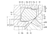
以下に、本発明におけるトラニオン型ボールバルブの実施形態並びに作用を図面に基づいて説明する。図1においては、本発明のトラニオン型ボールバルブの実施形態を示し、図2においては、図1のトラニオン型ボールバルブが弁閉したときの一次側(上流側)の要部拡大断面を示している。 Hereinafter, embodiments and operations of a trunnion type ball valve according to the present invention will be described with reference to the drawings. FIG. 1 shows an embodiment of the trunnion type ball valve of the present invention, and FIG. 2 shows an enlarged cross-sectional view of the main part (upstream side) of the primary side (upstream side) when the trunnion type ball valve of FIG. 1 is closed. Yes.
図1のトラニオン型ボールバルブ(以下、バルブ本体10という)は、ボデー11、ボール12、ステム13、シートリテーナ14、ボールシート15を有し、特に、大口径であって、クラス(呼び圧力)150〜2500程度の高圧流体用として用いる場合に適している。
1 has a body 11, a
ボデー11は、環状ボデー20と両側の環状のキャップ21、21とを有し、これらは炭素鋼やステンレス材料などにより設けられ、ボルトナット22により一体化される。
ボデー11内には、上ステム12a、下ステム13bからなるステム13を介してボール12が回動可能に設けられ、このボール12の双方、すなわち上下流側にシートリテーナ14が配設され、このシートリテーナ14にボールシート15が取付けられる。ボール12はステンレス鋼を材料として形成され、バルブ本体10内の流路23と連通可能な貫通孔12aが設けられる。本実施形態では、ボール12の上下流側にボールシート15、シートリテーナ14が取付けられているが、これらは少なくとも上流側に設けられていればよい。図1のように上下流側にボールシート15、シートリテーナ14が取付けられているボールバルブ本体10の場合、図において右側又は左側の何れの側を一次側としてもよい。
The body 11 has an
In the body 11, a
図2において、ボールシート15は、PTFE(ポリテトラフルオロエチレン)やナイロン、PEEK(ポリエーテルエーテルケトン)などの樹脂材料により弾性変形可能な環状に形成され、ボール12の当接側には環状のシール部位25が設けられる。
ボールシート15は、後述するシートリテーナ14に形成された装着溝26にフリーな状態で装着され、このボールシート15の装着溝26側には、装着溝26に当接して背面シール可能に設けられ、支点位置となるA部が環状に突出形成されている。
In FIG. 2, a
The
本発明において、「ボールシート15がシートリテーナ14に形成された装着溝26内にフリーな状態で装着される」とは、ボールシート15が、装着溝26からの飛び出しが防止され、かつ、支点位置A部を中心にボール12側が開口する方向に弾性変形可能な状態で、バルブ本体10の流路軸芯Pの方向に移動可能な状態で装着されている状態をいう。
In the present invention, “the
A部の内径寸法L1は、ボールシート15のシール部位25よりも内径寄りに設けられ、このようにA部が環状に突設形成されていることにより、ボールシート15と装着溝26の有底穴34との間には間隙Hが形成される。ボールシート15は、高圧時においてA部を支点として開くように弾性変形して、シール部位25を外径より内径側に向けてボール12に少なくとも面接触状態にシールするように設けられる。その際、間隙Hを設けていることで、この間隙Hもボールシート15の開くように弾性変形するときの回転作用に寄与している。
The inner diameter dimension L1 of the A portion is provided closer to the inner diameter than the
シール部位25は、ボール12外周に面接触可能な球状面である球面部により形成され、シール部位25の流路23方向における一次側に封止部C、二次側に封止部Bが形成され、低圧時において封止部Bがボール12に線接触可能に設けられている。
The
支点位置であるA部と、シール部位25である封止部B及び封止部Cの位置関係は、封止部Bの内径寸法をL2、封止部Cの内径寸法をL3としたときに、A部、封止部B、封止部Cの内径寸法に対してA<C<Bとなるように、内径寸法L1<内径寸法L3<内径寸法L2となるように設けられる。
The positional relationship between the A portion that is the fulcrum position and the sealing portion B and the sealing portion C that are the
さらに、図2に示すように、ボールシート15が装着溝26に装着された組立初期、及び流体圧が低圧であるときには、シール部位25の封止部Cから封止部Bまでの内径φDSがボール12の球径φDBと異なり、これらが異径寸法になるように形成される。本実施形態においては、内径φDSがボール球径φDBよりも縮径した形状、すなわち、シール部内径φDS<ボール球径φDBの関係になるように形成されている。これらの内径φDSの中心P1、ボール球径φDBの中心P2は、図3に示すように、何れもバルブ本体10の流路軸芯P上に配置されている。
Furthermore, as shown in FIG. 2, when the
これらによって、組立初期及び流体圧力が低圧の場合、封止部Bのボール12への接触が線接触状態に保持され、かつ封止部Cがボール面16に非接触状態となる。
As a result, in the initial stage of assembly and when the fluid pressure is low, the contact of the sealing portion B with the
装着溝26の内周面26aとボールシート15のシール面側の外周面15aとの間には、所定のクリアランスGが設けられ、高圧時にはこのクリアランスG側にボールシート15が開くようにすると共に、開き過ぎが抑制されるようになっている。
A predetermined clearance G is provided between the inner
ボールシート外周面15aには、装着溝26の奥側に、突起状の係合部32がボールシート15の装着方向の厚さに対して略半分程度の長さに形成される。一方、シートリテーナ14の装着溝26には、突起状の係止部33が開口側から装着溝26の長さの略半分程度まで形成される。少なくとも係止部33の内周面26aと、ボールシート15の係合部32よりもボール12側の外周面15a側との間に、上記のクリアランスGが設けられる。
On the outer
図1に示すように、シートリテーナ14は、炭素鋼或はステンレス材料などの金属材料により略円筒状に設けられ、前述したボールシート15の装着側がやや拡径するように形成され、その内部には、ボールシート15を装入可能な環状の装着溝26が設けられる。
係止部33の奥側には、係合部32の外径よりも大径の有底穴34が設けられ、この有底穴34の深さは係合部32の長さよりも大きく形成され、有底穴34の内径は係合部32の外径よりもやや大きく形成される。
As shown in FIG. 1, the
A bottomed
シートリテーナ14には、係合部32が有底穴34に収容された状態でボールシート15が装着溝26に装着される。ボールシート15の装着後には、係合部32の後端側と係止部33の後端側とが係合部32の装入方向に係止可能に対向することで、ボールシート15の装着溝26からの飛び出しが防止されつつ、ボールシート15がフリーな状態となる。シートリテーナ14のボールシート15装着側との反対側には、コイルばね40が弾発状態でキャップ21との間に装着される。これにより、ボールシート15は、コイルばね40によりシートリテーナ14を介してボール12に押圧されている。シートリテーナ14とキャップ21との間は、Oリング41やパッキン42によりシールされている。
In the
ボールシート15のシートリテーナ14への装着後には、ボールシート15の内周面15b側と外周側(係合部32側)との間にキャビティ35とボール12の上流側とを連通する連通部36が設けられる。これにより、全閉時または全開時のバルブ本体10のキャビティ35内の異常昇圧による余剰の圧力は、シートリテーナ14の自緊力でボール12とは反対方向に移動され、かつ、装着溝26内のボールシート15の裏面側に流入した流体圧でボールシート15がボール12側に押し出され、このとき連通部36を介してキャビティ35内の異常昇圧が流路23内にリリーフされる。ここで、キャビティ35内の異常昇圧とは、流体の温度が上昇したり、バルブ本体10が設置されている環境が高温となることにより、弁閉状態のバルブ本体10において、ボデー11やボール12、ボールシート15、シートリテーナ14等により囲まれた、閉じられた空間(キャビティ35)内の圧力が上昇する現象をいう。
After the
本発明のトラニオン型ボールバルブは、8インチ以上の大口径である場合に好適であり、本実施形態では、例えば、クラス600のサイズ12Bのバルブ本体1の場合、ボールシート材質:PTFE、ボール球径:φ460mm、シール部の内径φDSがボール球径φDBに対して3%から5%程度縮径し、封止部Cの内径(内径寸法L3)と支点位置であるA部の内径(内径寸法L1)との寸法差:2mm以下(半径方向において1mm以下)、封止部Bの内径(内径寸法L2)と封止部Cの内径(内径寸法L3)との寸法差:2mm以上(半径方向において1mm以上)とすればよい。この場合、高圧負荷時のボールシート15のボール12側への開口する弾性変形を1°程度拡径すると想定するものとする。
The trunnion type ball valve of the present invention is suitable for a large diameter of 8 inches or more. In this embodiment, for example, in the case of a valve body 1 of class 600 size 12B, ball seat material: PTFE, ball ball Diameter: φ460 mm, the inner diameter φDS of the seal part is reduced by about 3% to 5% with respect to the ball ball diameter φDB, and the inner diameter (inner diameter dimension L3) of the sealing part C and the inner diameter of the A part (inner diameter dimension). Dimensional difference from L1): 2 mm or less (1 mm or less in the radial direction), Dimensional difference between the inner diameter (inner diameter dimension L2) of the sealing part B and the inner diameter (inner diameter dimension L3) of the sealing part C: 2 mm or more (radial direction) 1 mm or more). In this case, it is assumed that the elastic deformation that opens to the
なお、ボールシート15のシール部位25はボール12へのシール付近に設けられ、流体圧の高さに応じてボール12に線接触ないし面接触してシール可能であれば球面部以外の形状であってもよく、例えばテーパ状や円弧面状に形成されていてもよい。
The sealing
図示しないが、ボールシート15の係合部32、シートリテーナ14の係止部33には、それぞれ、相互に螺着可能なおねじ、めねじを形成し、これらおねじとめねじとを介してボールシート15を装着溝26に装着してもよい。
係止部33にめねじを設けた場合、その内周面26aはねじ山となる。高圧時に弾性変形したボールシート15は、その外周面15aが前記のねじ山にくい込むことにより、装着溝26からの飛び出しや、高圧下におけるバルブ本体1の開閉操作時のボールシート15の浮き上がり現象を防ぎ、ボールシート15の耐久性を更に向上することができる。
Although not shown in the drawings, the engaging
When an internal thread is provided in the locking
また、図示しないが、サイズ10B以上の大口径バルブについては、ボールシート15の外周に締付治具により締付け或は取外し可能となる溝や穴が設けられていてもよく、この場合、ボールシート15の組付けが容易になる。
Although not shown, for a large-diameter valve of size 10B or more, a groove or hole that can be tightened or removed by a tightening jig may be provided on the outer periphery of the
シートリテーナ14にボールシート15を装着する場合には、係止部33に対して係合部32を押し込むようにボールシート15を装着溝26方向に開口側から装入するようにする。係合部32が有底穴34に達したときにボールシート15の装着が完了し、ボールシート15がシートリテーナ14に対して抜け止めされ、フリーな状態で装着される。このとき、前記したように有底穴34の深さが係合部32の長さよりも大きいことで、この係合部32が係止部33の領域を確実に超えて、係合部32が有底穴34に収容される。
When the
ボールシート15の装入後には、装着溝26との間にクリアランスGが形成され、このクリアランスGによりボールシート15のボール12側が支点位置となるA部を中心に開口する方向に弾性変形可能になる。
係合部32と係止部33との間の図2に示すように装入方向(図1の流路の流路軸芯Pの方向)には、空間Sが設けられる。有底穴34の内径が係合部32の外径よりもやや大きく設けられていることで、これらの間には径方向の隙間Lも設けられる。この隙間Lにより、ボールシート15がシートリテーナ14の空間Sの範囲において、摺動抵抗の少ない状態で進退可能となる。
After the
As shown in FIG. 2 between the engaging
クリアランスG、空間S、隙間Lの大きさなどの寸法設定は、組立て時の環境温度や、組立場所の違いによる寒暖差を考慮した上で設定される。本実施形態の場合、夏季で最高40℃、冬季で最低10℃の組立て温度に対応できるように設けられている。 The dimensions such as the size of the clearance G, the space S, and the gap L are set in consideration of the environmental temperature at the time of assembly and the temperature difference due to the difference in the assembly location. In the case of this embodiment, it is provided so as to be able to cope with an assembly temperature of a maximum of 40 ° C. in the summer and a minimum of 10 ° C. in the winter.
次に、本発明のトラニオン型ボールバルブの上記実施形態における作用を説明する。
図1のバルブ本体10において、流路23の上流側の流体圧が低圧である場合には、図2に示すように、ボールシート15のA部が装着溝26の底面側に当接した状態で封止部Bがボール12に線接触してシールした状態を保つ。この線接触によるシールは面接触のシールに比較してシール力は低下するが、流体が低圧であるためにボールシート材質の降伏点まで到達しないことにより、シール性能を損なう摩耗が生じることがなく、この低圧時の漏れを確実に防止する。
Next, the operation of the above-described embodiment of the trunnion type ball valve of the present invention will be described.
In the
高圧の流体圧が加わる場合には、シートリテーナ14にはコイルばね40の弾発力に加え、高圧の流体圧を利用した自緊力が加わるため、ボールシート15は更にボール12側に押され、図4に示すように流体圧の高さに応じてボールシート15がA部を中心にボール12側が開口する方向に弾性変形し、シール部位25を外径側より内径側に向けてボール12に対して少なくとも面接触状態にシールすることにより、高圧の流体を確実に封止できる。
When a high fluid pressure is applied, the
この場合、図2において、支点位置であるA部とシール部位である封止部B及び封止部Cの位置関係を、内径寸法に対してA<C<Bとしており、A部よりも外径側に封止部Bが位置していることで、図4の回転作用において封止部B側が確実にボール12から離れる方向に移動するように左回転し、この回転によりそれまでボール12から離間していた封止部C側がボール12に確実に面接触する。
In this case, in FIG. 2, the positional relationship between the A portion that is the fulcrum position and the sealing portion B and the sealing portion C that are the seal portions is A <C <B with respect to the inner diameter dimension, and is outside the A portion. Since the sealing portion B is positioned on the radial side, the sealing portion B side rotates counterclockwise so that the sealing portion B side moves in a direction away from the
装着溝26とボールシート15との間に所定のクリアランスGを設けていることにより、シール部位25側が開口方向に変形する際の動作が阻害されることが防がれ、且つ、ボールシート15の外周面15aが装着溝26の内周面26aに接触することにより、ボールシート15の開き過ぎを抑制してボール12へのシール状態を確保できる。
By providing a predetermined clearance G between the mounting
さらには、ボールシート15を装着溝26にフリーな状態で装着する構造であることを利用してボールシート15の内周面15bと装着溝26との間に連通部36を設けていることで、この連通部36を介して流路23内にキャビティ35内の異常昇圧による余剰の圧力をリリーフできる。これにより、キャビティ35内の異常昇圧をボールシート15とボール12との間からリリーフする必要がなくなり、これらボールシート15やボール12の摩耗を抑えてシール性を確保し、耐久性を向上できる。
Furthermore, by utilizing the structure in which the
以上、本発明の実施の形態について詳述したが、本発明は、前記実施の形態記載に限定されるものではなく、本発明の特許請求の範囲に記載されている発明の精神を逸脱しない範囲で、種々の変更ができるものである。 Although the embodiment of the present invention has been described in detail above, the present invention is not limited to the description of the embodiment, and the scope does not depart from the spirit of the invention described in the claims of the present invention. Thus, various changes can be made.
10 バルブ本体
11 ボデー
12 ボール
12a 貫通孔
13 ステム
14 シートリテーナ
15 ボールシート
15a 外周面
16 ボール面
25 シール部位
26 装着溝
26a 内周面
A部 支点位置
B、C 封止部
G クリアランス
L1、L2、L3 内径寸法
DESCRIPTION OF
Claims (6)
Priority Applications (8)
| Application Number | Priority Date | Filing Date | Title |
|---|---|---|---|
| JP2015014295A JP6474262B2 (en) | 2015-01-28 | 2015-01-28 | Trunnion type ball valve |
| PCT/JP2015/074234 WO2016067737A1 (en) | 2014-10-28 | 2015-08-27 | Trunnion-type ball valve |
| US15/108,685 US10018276B2 (en) | 2014-10-28 | 2015-08-27 | Trunnion-type ball valve |
| ES15855254T ES2813378T3 (en) | 2014-10-28 | 2015-08-27 | Trunnion type ball valve |
| CN201580059196.4A CN107110385B (en) | 2014-10-28 | 2015-08-27 | Fixed ball valve |
| EP15855254.7A EP3098491B1 (en) | 2014-10-28 | 2015-08-27 | Trunnion-type ball valve |
| KR1020167017726A KR101956090B1 (en) | 2014-10-28 | 2015-08-27 | Trunnion-type ball valve |
| TW105101556A TWI650501B (en) | 2015-01-28 | 2016-01-19 | Trunnion type ball valve |
Applications Claiming Priority (1)
| Application Number | Priority Date | Filing Date | Title |
|---|---|---|---|
| JP2015014295A JP6474262B2 (en) | 2015-01-28 | 2015-01-28 | Trunnion type ball valve |
Publications (3)
| Publication Number | Publication Date |
|---|---|
| JP2016138609A JP2016138609A (en) | 2016-08-04 |
| JP2016138609A5 JP2016138609A5 (en) | 2018-03-08 |
| JP6474262B2 true JP6474262B2 (en) | 2019-02-27 |
Family
ID=56559062
Family Applications (1)
| Application Number | Title | Priority Date | Filing Date |
|---|---|---|---|
| JP2015014295A Active JP6474262B2 (en) | 2014-10-28 | 2015-01-28 | Trunnion type ball valve |
Country Status (2)
| Country | Link |
|---|---|
| JP (1) | JP6474262B2 (en) |
| TW (1) | TWI650501B (en) |
Families Citing this family (4)
| Publication number | Priority date | Publication date | Assignee | Title |
|---|---|---|---|---|
| JP6426435B2 (en) * | 2014-10-28 | 2018-11-21 | 株式会社キッツ | Trunnion type ball valve |
| CN107725802A (en) * | 2017-11-02 | 2018-02-23 | 苏州丹顿机电有限公司 | A kind of anti-leakage valve |
| JP6710254B2 (en) * | 2018-10-24 | 2020-06-17 | 株式会社キッツ | Trunnion type ball valve |
| CN113864477A (en) * | 2021-10-09 | 2021-12-31 | 欧维克集团有限公司 | High-pressure duplex floating ball valve |
Family Cites Families (8)
| Publication number | Priority date | Publication date | Assignee | Title |
|---|---|---|---|---|
| US3269693A (en) * | 1965-05-24 | 1966-08-30 | Acf Ind Inc | Ball valve seat |
| GB1142441A (en) * | 1967-04-14 | 1969-02-05 | Masheder Design Studies Ltd | Improvements in ball valves |
| US4410165A (en) * | 1982-02-16 | 1983-10-18 | Whitey Co. | Ball valve and seat assembly |
| JPS58148365U (en) * | 1982-03-30 | 1983-10-05 | 日立金属株式会社 | ball valve |
| TWI230770B (en) * | 2003-12-19 | 2005-04-11 | Metal Ind Res & Dev Ct | Positive-action and anti-leak structure of a ball valve |
| JP5096285B2 (en) * | 2008-10-27 | 2012-12-12 | 株式会社キッツ | Ball valve |
| US8002237B2 (en) * | 2008-11-12 | 2011-08-23 | Velan Inc. | Seat arrangement with cavity pressure relief for a ball valve |
| TWM472782U (en) * | 2013-11-15 | 2014-02-21 | Transworld Steel Entpr Co Ltd | Ball pad pressure relief structure of ball valve |
-
2015
- 2015-01-28 JP JP2015014295A patent/JP6474262B2/en active Active
-
2016
- 2016-01-19 TW TW105101556A patent/TWI650501B/en active
Also Published As
| Publication number | Publication date |
|---|---|
| JP2016138609A (en) | 2016-08-04 |
| TWI650501B (en) | 2019-02-11 |
| TW201638509A (en) | 2016-11-01 |
Similar Documents
| Publication | Publication Date | Title |
|---|---|---|
| WO2016067737A1 (en) | Trunnion-type ball valve | |
| US10801627B2 (en) | Valve seats, valve assemblies, and related methods | |
| EP2564095B1 (en) | Sleeve seal assembly and rotary valve having sleeve seal assembly | |
| JP6474262B2 (en) | Trunnion type ball valve | |
| WO2016182066A1 (en) | Trunnion-type ball valve, sealing structure of valve, and packing for valve | |
| JP2009041776A (en) | Ball valve | |
| US9341273B2 (en) | Composite dynamic valve seal assembly for high temperature control valves | |
| US9360128B2 (en) | Graphite/metal valve seal assembly for high temperature control valves | |
| US9395019B2 (en) | Device for sealing a valve | |
| GB1561593A (en) | Valve structure | |
| JP2012013141A (en) | Trunnion type ball valve | |
| JP7191035B2 (en) | valve | |
| JP6820814B2 (en) | Eccentric rotary valve | |
| JP2017096323A (en) | Lining type butterfly valve | |
| JP6426435B2 (en) | Trunnion type ball valve | |
| CN107917228B (en) | Eccentric rotary valve | |
| JP2018013170A (en) | Lining-type butterfly valve | |
| JP2017067083A (en) | Lining type butterfly valve | |
| HU176259B (en) | Sealing ring for butterly valve |
Legal Events
| Date | Code | Title | Description |
|---|---|---|---|
| A521 | Request for written amendment filed |
Free format text: JAPANESE INTERMEDIATE CODE: A523 Effective date: 20180123 |
|
| A621 | Written request for application examination |
Free format text: JAPANESE INTERMEDIATE CODE: A621 Effective date: 20180123 |
|
| TRDD | Decision of grant or rejection written | ||
| A01 | Written decision to grant a patent or to grant a registration (utility model) |
Free format text: JAPANESE INTERMEDIATE CODE: A01 Effective date: 20190108 |
|
| A61 | First payment of annual fees (during grant procedure) |
Free format text: JAPANESE INTERMEDIATE CODE: A61 Effective date: 20190129 |
|
| R150 | Certificate of patent or registration of utility model |
Ref document number: 6474262 Country of ref document: JP Free format text: JAPANESE INTERMEDIATE CODE: R150 |
|
| R250 | Receipt of annual fees |
Free format text: JAPANESE INTERMEDIATE CODE: R250 |
|
| R250 | Receipt of annual fees |
Free format text: JAPANESE INTERMEDIATE CODE: R250 |
|
| S531 | Written request for registration of change of domicile |
Free format text: JAPANESE INTERMEDIATE CODE: R313531 |
|
| R350 | Written notification of registration of transfer |
Free format text: JAPANESE INTERMEDIATE CODE: R350 |
|
| R250 | Receipt of annual fees |
Free format text: JAPANESE INTERMEDIATE CODE: R250 |