JP6471167B2 - Toothbrush holder device - Google Patents
Toothbrush holder device Download PDFInfo
- Publication number
- JP6471167B2 JP6471167B2 JP2016543273A JP2016543273A JP6471167B2 JP 6471167 B2 JP6471167 B2 JP 6471167B2 JP 2016543273 A JP2016543273 A JP 2016543273A JP 2016543273 A JP2016543273 A JP 2016543273A JP 6471167 B2 JP6471167 B2 JP 6471167B2
- Authority
- JP
- Japan
- Prior art keywords
- toothbrush
- head
- proposed solution
- clip
- holder
- Prior art date
- Legal status (The legal status is an assumption and is not a legal conclusion. Google has not performed a legal analysis and makes no representation as to the accuracy of the status listed.)
- Active
Links
- 230000002093 peripheral effect Effects 0.000 claims description 17
- 238000003780 insertion Methods 0.000 claims description 13
- 230000037431 insertion Effects 0.000 claims description 13
- 239000013013 elastic material Substances 0.000 claims description 5
- 239000000243 solution Substances 0.000 description 112
- 238000010586 diagram Methods 0.000 description 80
- 230000005484 gravity Effects 0.000 description 8
- 239000000463 material Substances 0.000 description 5
- 229920000642 polymer Polymers 0.000 description 4
- 239000000853 adhesive Substances 0.000 description 3
- 230000001070 adhesive effect Effects 0.000 description 3
- 238000004140 cleaning Methods 0.000 description 3
- 238000011109 contamination Methods 0.000 description 3
- 238000000034 method Methods 0.000 description 3
- 238000006243 chemical reaction Methods 0.000 description 2
- 238000004519 manufacturing process Methods 0.000 description 2
- 230000013011 mating Effects 0.000 description 2
- 230000003014 reinforcing effect Effects 0.000 description 2
- 238000005452 bending Methods 0.000 description 1
- 230000009286 beneficial effect Effects 0.000 description 1
- 230000008878 coupling Effects 0.000 description 1
- 238000010168 coupling process Methods 0.000 description 1
- 238000005859 coupling reaction Methods 0.000 description 1
- 239000012530 fluid Substances 0.000 description 1
- 239000003292 glue Substances 0.000 description 1
- 238000002347 injection Methods 0.000 description 1
- 239000007924 injection Substances 0.000 description 1
- 239000002184 metal Substances 0.000 description 1
- 239000003607 modifier Substances 0.000 description 1
- 239000012858 resilient material Substances 0.000 description 1
- 239000007779 soft material Substances 0.000 description 1
- 238000003860 storage Methods 0.000 description 1
- 239000000126 substance Substances 0.000 description 1
- 230000002195 synergetic effect Effects 0.000 description 1
- 238000005406 washing Methods 0.000 description 1
- 239000002023 wood Substances 0.000 description 1
Images


Classifications
-
- A—HUMAN NECESSITIES
- A47—FURNITURE; DOMESTIC ARTICLES OR APPLIANCES; COFFEE MILLS; SPICE MILLS; SUCTION CLEANERS IN GENERAL
- A47K—SANITARY EQUIPMENT NOT OTHERWISE PROVIDED FOR; TOILET ACCESSORIES
- A47K1/00—Wash-stands; Appurtenances therefor
- A47K1/08—Accessories for toilet tables, e.g. glass plates, supports therefor
- A47K1/09—Holders for drinking glasses, tooth brushes, hair brushes, or the like
-
- A—HUMAN NECESSITIES
- A46—BRUSHWARE
- A46B—BRUSHES
- A46B17/00—Accessories for brushes
- A46B17/02—Devices for holding brushes in use
-
- A—HUMAN NECESSITIES
- A46—BRUSHWARE
- A46B—BRUSHES
- A46B17/00—Accessories for brushes
- A46B17/04—Protective covers for the bristles
-
- A—HUMAN NECESSITIES
- A47—FURNITURE; DOMESTIC ARTICLES OR APPLIANCES; COFFEE MILLS; SPICE MILLS; SUCTION CLEANERS IN GENERAL
- A47G—HOUSEHOLD OR TABLE EQUIPMENT
- A47G29/00—Supports, holders, or containers for household use, not provided for in groups A47G1/00-A47G27/00 or A47G33/00
- A47G29/08—Holders for articles of personal use in general, e.g. brushes
-
- F—MECHANICAL ENGINEERING; LIGHTING; HEATING; WEAPONS; BLASTING
- F16—ENGINEERING ELEMENTS AND UNITS; GENERAL MEASURES FOR PRODUCING AND MAINTAINING EFFECTIVE FUNCTIONING OF MACHINES OR INSTALLATIONS; THERMAL INSULATION IN GENERAL
- F16B—DEVICES FOR FASTENING OR SECURING CONSTRUCTIONAL ELEMENTS OR MACHINE PARTS TOGETHER, e.g. NAILS, BOLTS, CIRCLIPS, CLAMPS, CLIPS OR WEDGES; JOINTS OR JOINTING
- F16B2/00—Friction-grip releasable fastenings
- F16B2/20—Clips, i.e. with gripping action effected solely by the inherent resistance to deformation of the material of the fastening
- F16B2/22—Clips, i.e. with gripping action effected solely by the inherent resistance to deformation of the material of the fastening of resilient material, e.g. rubbery material
-
- F—MECHANICAL ENGINEERING; LIGHTING; HEATING; WEAPONS; BLASTING
- F16—ENGINEERING ELEMENTS AND UNITS; GENERAL MEASURES FOR PRODUCING AND MAINTAINING EFFECTIVE FUNCTIONING OF MACHINES OR INSTALLATIONS; THERMAL INSULATION IN GENERAL
- F16M—FRAMES, CASINGS OR BEDS OF ENGINES, MACHINES OR APPARATUS, NOT SPECIFIC TO ENGINES, MACHINES OR APPARATUS PROVIDED FOR ELSEWHERE; STANDS; SUPPORTS
- F16M13/00—Other supports for positioning apparatus or articles; Means for steadying hand-held apparatus or articles
- F16M13/02—Other supports for positioning apparatus or articles; Means for steadying hand-held apparatus or articles for supporting on, or attaching to, an object, e.g. tree, gate, window-frame, cycle
-
- A—HUMAN NECESSITIES
- A46—BRUSHWARE
- A46B—BRUSHES
- A46B2200/00—Brushes characterized by their functions, uses or applications
- A46B2200/10—For human or animal care
- A46B2200/1066—Toothbrush for cleaning the teeth or dentures
-
- A—HUMAN NECESSITIES
- A47—FURNITURE; DOMESTIC ARTICLES OR APPLIANCES; COFFEE MILLS; SPICE MILLS; SUCTION CLEANERS IN GENERAL
- A47B—TABLES; DESKS; OFFICE FURNITURE; CABINETS; DRAWERS; GENERAL DETAILS OF FURNITURE
- A47B81/00—Cabinets or racks specially adapted for other particular purposes, e.g. for storing guns or skis
- A47B81/02—Cabinets or racks specially adapted for other particular purposes, e.g. for storing guns or skis specially adapted for storing cleaning utensils
-
- A—HUMAN NECESSITIES
- A47—FURNITURE; DOMESTIC ARTICLES OR APPLIANCES; COFFEE MILLS; SPICE MILLS; SUCTION CLEANERS IN GENERAL
- A47L—DOMESTIC WASHING OR CLEANING; SUCTION CLEANERS IN GENERAL
- A47L13/00—Implements for cleaning floors, carpets, furniture, walls, or wall coverings
- A47L13/10—Scrubbing; Scouring; Cleaning; Polishing
- A47L13/50—Auxiliary implements
- A47L13/51—Storing of cleaning tools, e.g. containers therefor
- A47L13/512—Clamping devices for hanging the tools
Description
本発明は、歯ブラシ筐体に関し、より詳細には歯ブラシの衛生的な保管のための整然とした歯ブラシホルダー装置に関する。 The present invention relates to a toothbrush housing, and more particularly to an orderly toothbrush holder device for hygienic storage of toothbrushes.
整然とした衛生的な歯ブラシ筐体を提供する必要性が高まっている。歯ブラシ筐体の1つのタイプは、歯ブラシ筐体を壁に取り付けることにより整然とさせる。この点に関して、従来の歯ブラシを保管するために多くの試みがなされてきた。 There is a growing need to provide an orderly and hygienic toothbrush housing. One type of toothbrush housing is made orderly by attaching the toothbrush housing to a wall. In this regard, many attempts have been made to store conventional toothbrushes.
国際公開第1998/35585A1号公報は、概して3つの部分、すなわちラックを壁に取り付けるための背板、歯ブラシ頭部を側部から係合するためのホルダー、および筐体を提供するための外郭を有する、歯ブラシラックを開示している。歯ブラシは、ホルダーの指部の間で3点を保持することよりラック内に固定され、背板上に置くことにより回転を防ぐ。残念ながら、歯ブラシに接触する背板を洗浄のために容易に取り外すことができないので、このようなラックは所望するほど衛生的ではない。また軟質材料を組み込むより最近の歯ブラシの設計は、歯ブラシを取り外すために分解を必要とするラックに差し込まれる傾向がある。 WO 1998/35585 A1 generally has three parts: a back plate for mounting the rack to the wall, a holder for engaging the toothbrush head from the side, and a shell for providing a housing. A toothbrush rack is disclosed. The toothbrush is fixed in the rack by holding three points between the fingers of the holder, and prevents rotation by placing it on the back plate. Unfortunately, such racks are not as hygienic as desired because the backplate that contacts the toothbrush cannot be easily removed for cleaning. Also, more recent toothbrush designs that incorporate soft materials tend to be plugged into racks that require disassembly to remove the toothbrush.
米国特許第4,396,238号は、2つの部分の筐体を開示している。箱は、壁に装着するための背板、側部パネル、および歯ブラシの柄を挿入する底部開口を含む。楔形状の蓋は、その重心により蓋が箱の上に載るように側壁にヒンジで連結される。残念ながら、歯ブラシの柄を上部から底部開口を通って供給するためには巧妙性を高める必要がある。すべての歯ブラシの柄を単一の底部開口設計によって収納することはできない。上記のように、歯ブラシは箱に支持され、箱は洗浄のために壁から容易に取り外すことができず、したがって決して衛生的な解決をもたらさない。 U.S. Pat. No. 4,396,238 discloses a two part housing. The box includes a back plate for mounting on a wall, a side panel, and a bottom opening into which a toothbrush handle is inserted. The wedge-shaped lid is hinged to the side wall so that the lid rests on the box by its center of gravity. Unfortunately, in order to feed the toothbrush handle from the top through the bottom opening, it is necessary to increase the sophistication. Not all toothbrush handles can be accommodated by a single bottom opening design. As mentioned above, the toothbrush is supported on the box, and the box cannot be easily removed from the wall for cleaning and therefore never provides a hygienic solution.
米国特許第5,332,107号は、背壁、側壁および上壁を有するスナップキャップ筐体、底部スロットならびにヒンジドアを開示している。歯ブラシ頸部はスロット内に係合される。スナップキャップ筐体全体は壁に取り付けられた板から取り外し可能である一方で、歯ブラシ頭部は非常に頻繁にその洗浄が必要なスナップキャップ筐体の内側に自由に接触することができる。またスナップ行為の反復により部品を非常に急速に摩耗させる傾向があり、この提案を実現不可能にさせる。 U.S. Pat. No. 5,332,107 discloses a snap cap housing having a back wall, side walls and a top wall, a bottom slot and a hinge door. The toothbrush neck is engaged in the slot. While the entire snap cap housing is removable from the wall mounted plate, the toothbrush head is free to contact the inside of the snap cap housing that needs to be cleaned very often. Also, repeated snapping tends to wear parts very quickly, making this proposal unfeasible.
米国特許第3,977,743号は、壁ブラケットに埋め込まれた単一の成型品から作成された上記のスナップキャップと同様の筐体を開示している。筐体は背壁およびスロットのある底壁を備えた背部、上壁、正面壁、側壁および部分底壁を有するカバー部、ならびに背部およびカバー部を一体化するヒンジを有する。スロットは歯ブラシ頸部で歯ブラシを保持するように形状され、部分底壁はスロットに挿入された歯ブラシに当たる。筐体は充分に大きく作成されるので歯ブラシ頭部が上壁、側壁、背壁および正面壁に接触するのを防ぐことができる一方で、歯ブラシの毛は部分底壁上に置かれるので頻繁に洗浄する必要がある。その上、形状されたスロットには歯ブラシの形状との一致に限界がある。 U.S. Pat. No. 3,977,743 discloses a housing similar to the above-described snap cap made from a single molded article embedded in a wall bracket. The housing has a back with a back wall and a slotted bottom wall, a top wall, a front wall, a cover having side walls and a partial bottom wall, and a hinge that unifies the back and cover. The slot is shaped to hold the toothbrush at the toothbrush neck and the partial bottom wall abuts the toothbrush inserted into the slot. The housing is made large enough to prevent the toothbrush head from contacting the top wall, side wall, back wall and front wall, while the toothbrush bristles are often placed on the partial bottom wall Need to be cleaned. In addition, the shaped slots are limited in matching the shape of the toothbrush.
英国特許第1,061,092号および欧州特許第90103657号は、歯ブラシをその中に保持するための手段として、歯ブラシの弾性の毛に直接係合するように構成された歯ブラシ筐体を開示している。残念ながら、このような筐体は使用する毎に洗浄を必要とする。 British Patent No. 1,061,092 and European Patent No. 90103657 disclose toothbrush housings configured to directly engage the elastic bristles of the toothbrush as a means for retaining the toothbrush therein. ing. Unfortunately, such enclosures require cleaning each time they are used.
先行技術における上記の欠点は、機能部分として、背板、弾性クランプおよび正面カバーを含む3つの部分の歯ブラシホルダー装置を利用することによって対処される。背板および正面カバーはハウジングを形成する一方で、背板、クランプおよび正面カバーは歯ブラシ筐体を提供する。クランプ部は概ね逆U字形を有し、好ましくはばね特性を与える弾性材料から作成される。クランプは、クランプ全体が保持具として作用するために、2つの把持アームを互いに向かわせるように形状される。好ましくは、把持アームの先端における2つのローラは、クランプが固定位置から外れた状態に離間されると、クランプに挿入された歯ブラシ頭部を係合する。歯ブラシが挿入された状態で、ローラは歯ブラシを速やかに定位置に保持するために、歯ブラシの頸部に圧力をかける。ローラの回転係合作用により、ゴム側部に一致する頭部を有する歯ブラシを歯ブラシ筐体内に保持でき、歯ブラシホルダーに対して歯ブラシの非常に多い流体運動が可能になる。小型のタブをクランプに組み込むことができ、これを背板と組み合わせて歯ブラシが筐体の中に挿入された際に歯ブラシを単一配向に限定する。 The above disadvantages in the prior art are addressed by utilizing as a functional part a three part toothbrush holder device including a back plate, an elastic clamp and a front cover. The back plate and front cover form a housing, while the back plate, clamp and front cover provide a toothbrush housing. The clamp has a generally inverted U shape and is preferably made from an elastic material that provides spring characteristics. The clamp is shaped to point the two gripping arms towards each other so that the entire clamp acts as a retainer. Preferably, the two rollers at the tip of the gripping arm engage the toothbrush head inserted into the clamp when the clamp is separated from the fixed position. With the toothbrush inserted, the roller applies pressure to the neck of the toothbrush to quickly hold the toothbrush in place. Due to the rotational engagement of the rollers, a toothbrush having a head coincident with the rubber side can be held in the toothbrush housing, allowing a very large fluid movement of the toothbrush relative to the toothbrush holder. A small tab can be incorporated into the clamp, which in combination with the back plate limits the toothbrush to a single orientation when the toothbrush is inserted into the housing.
提案された解決の一部の実施形態によれば、頭部、頭部から延びる歯ブラシの毛、柄部、および頭部と柄部との間の頸部を有する歯ブラシのための歯ブラシホルダーが提供され、該ホルダーは、互いに向かって付勢される2つの対向する把持部材を有するクランプであって、該把持部材は、頭部の挿入によって分離されるように、対向するローラを備える端部を有し、頭部はローラが頸部を保持できるまで該ローラの上を摺動できる、クランプと、歯ブラシがクランプによって保持されるときに歯ブラシの毛を保護するように適合されたカバー本体と、を備える。 According to some embodiments of the proposed solution, a toothbrush holder for a toothbrush having a head, a toothbrush bristle extending from the head, a handle and a neck between the head and the handle is provided. The holder is a clamp having two opposing gripping members biased toward each other, the gripping member having an end with opposing rollers so that they are separated by insertion of the head. A clamp that can slide over the roller until the roller can hold the neck, and a cover body adapted to protect the toothbrush bristles when the toothbrush is held by the clamp; Is provided.
提案された解決の他の実施形態によれば、頭部、頭部から延在する歯ブラシの毛、柄部、および頭部と柄部との間の頸部を有する歯ブラシのための歯ブラシホルダーが提供され、該ホルダーは、互いに向かって付勢される2つの対向する把持部材を有するクランプであって、該把持部材は、対向する切欠きが頸部を保持するまで、頭部の挿入によって分離されるとともに、クランプ内に摺動するように頭部を誘導するように互いから広がる該切欠きを備える端部を有するクランプと、歯ブラシがクランプによって保持されるときに歯ブラシの毛を保護するように適合されたカバー本体と、を備える。 According to another embodiment of the proposed solution, there is provided a toothbrush holder for a toothbrush having a head, bristles of a toothbrush extending from the head, a handle, and a neck between the head and the handle. Provided, the holder is a clamp having two opposing gripping members biased towards each other, the gripping members being separated by insertion of the head until the opposing notches hold the neck And a clamp having ends with the notches extending from one another to guide the heads to slide into the clamp and to protect the toothbrush bristles when the toothbrush is held by the clamp A cover body adapted to the above.
提案された解決のさらなる実施形態によれば、頭部、頭部から延びる歯ブラシの毛、柄部、および頭部と柄部との間の頸部を有する歯ブラシのための歯ブラシホルダーが提供され、該ホルダーは、互いに向かって付勢される2つの対向する把持部材を有するクランプであって、該把持部分は、クランプが頸部を保持できるまで頭部の挿入によって分離されるように、互いから広がる対向する切欠きを備える端部を有する、クランプと、少なくとも1つのタブを係合することにより頭部の挿入を阻止するように、該把持部材の少なくとも1つの該端部の一部から延在する該タブであって、頭部をクランプの中から該タブの側部に挿入することができる、少なくとも1つのタブと、歯ブラシがクランプによって保持されるときに歯ブラシの毛を保護するように適合されたカバー本体と、を備える。 According to a further embodiment of the proposed solution there is provided a toothbrush holder for a toothbrush having a head, a toothbrush bristle extending from the head, a handle, and a neck between the head and the handle, The holder is a clamp having two opposing gripping members that are biased toward each other such that the gripping portions are separated from each other so that they can be separated by insertion of the head until the clamp can hold the neck. Extending from a portion of the end of at least one of the gripping members to prevent insertion of the head by engaging the clamp with at least one tab having ends with opposing notches that extend. At least one tab that allows the head to be inserted into the side of the tab from within the clamp and retains the toothbrush bristles when the toothbrush is held by the clamp. Comprising a cover body adapted to, the.
提案された解決のさらなる実施形態によれば、頭部、頭部から延びる歯ブラシの毛、柄部、および頭部と柄部との間の頸部を有する歯ブラシのための歯ブラシホルダーが提供され、該ホルダーは、互いに向かって付勢される2つの対向する把持部材を有するクランプであって、クランプが頸部を保持できるまで、頭部の挿入によって分離されるように互いに広がる対向する端部と、頭部がクランプの中から肩部の1側部に挿入されるまで、該肩部を係合することにより頭部の挿入を阻止するように、該把持部材の該端部の一部から延在する該肩部と、を含むクランプと、歯ブラシがクランプによって保持されるときに歯ブラシの毛を保護するように適合されたカバー本体と、を備える。 According to a further embodiment of the proposed solution there is provided a toothbrush holder for a toothbrush having a head, a toothbrush bristle extending from the head, a handle, and a neck between the head and the handle, The holder is a clamp having two opposing gripping members that are biased toward each other, with opposing ends that extend apart so as to be separated by insertion of the head until the clamp can hold the neck. From a portion of the end of the gripping member to prevent insertion of the head by engaging the shoulder until the head is inserted into one side of the shoulder from within the clamp. A clamp including the shoulder, and a cover body adapted to protect the bristles of the toothbrush when the toothbrush is held by the clamp.
提案された解決のなお他の実施形態によれば、頭部、頭部から延びる歯ブラシの毛、柄部、および頭部と柄部との間の頸部を有する歯ブラシのための歯ブラシホルダーが提供され、該ホルダーは、互いに向かって付勢される2つの対向する把持部材を有するクランプであって、クランプが頸部を保持できるまで頭部の挿入によって分離されるように適合された端部を有するクランプと、歯ブラシがクランプによって保持されるときに歯ブラシの毛を保護するように適合されたカバー本体とを備え、クランプは筐体のために側部を提供する一方で、カバー本体は歯ブラシ頭部および歯ブラシの毛のために該筐体の正面および背面を提供する。 According to yet another embodiment of the proposed solution, a toothbrush holder is provided for a toothbrush having a head, a toothbrush bristle extending from the head, a handle, and a neck between the head and the handle. The holder is a clamp having two opposing gripping members biased towards each other, the end adapted to be separated by insertion of the head until the clamp can hold the neck And a cover body adapted to protect the toothbrush bristles when the toothbrush is held by the clamp, the clamp providing a side for the housing, while the cover body is the toothbrush head Provide the front and back of the housing for the bristles and toothbrush bristles.
提案された解決の一態様によれば、歯ブラシホルダー・ハウジングを壁に取り付けるための背板と、背板を係合するように構成され、2つの対向するアームの間に把持力を提供するようにさらに構成されたクランプであって、該アームはそれぞれ対応する先端を有し、該クランプアームは実質的にアーム先端に装着されたローラを有し、該ローラは頭部および頸部を有する歯ブラシを該歯ブラシ頭部の側部によって回転係合するように構成され、該歯ブラシが該クランプの把持部から重力に逆らって滑らないようにさらに構成される、クランプと、実質的な防滴ハウジングを形成する該背板と嵌合するように構成されたカバーであって、該ハウジングは、それを通って該歯ブラシ頭部が挿入され、該クランプの該把持力から引き抜かれる底部歯ブラシ挿入開口を有する、カバーと、を備える歯ブラシホルダー装置が提供される。 According to one aspect of the proposed solution, a back plate for attaching the toothbrush holder housing to the wall and a back plate configured to engage the back plate so as to provide a gripping force between two opposing arms. A clamp further configured with each arm having a corresponding tip, the clamp arm having a roller mounted substantially at the tip of the arm, the roller having a head and a neck. A clamp and a substantially drip-proof housing, wherein the toothbrush is configured to be rotationally engaged by a side of the toothbrush head, and further configured to prevent the toothbrush from slipping against gravity from the grip of the clamp. A cover configured to mate with the back plate to form, the housing having a bottom portion through which the toothbrush head is inserted and withdrawn from the gripping force of the clamp Having a brush insertion aperture, toothbrush holder device comprising a cover, is provided.
提案された解決の別の態様によれば、歯ブラシ頭部の汚染を防ぐための歯ブラシクランプが提供され、該クランプは、該歯ブラシをクリップ内に重力の垂直抗力に抵抗して保持する2つの対向する把持部材の間に把持力を提供するように構成されたクリップを備え、各把持部材は、歯ブラシ頭部をその側部によりスリップ係合するように位置付けられ構成された切欠きであって、両方の切欠きは、該歯ブラシ頭部および歯ブラシ頸部の少なくとも1つがクランプ内で把持されるようにチャネル状ガイドを形成する、切欠きと、両方のタブがその間に切込みを形成するように、該チャネル状ガイドに実質的に垂直に延在するタブであって、該タブは対応するタブ面の間でクランプ内に該歯ブラシが挿入されるのを防ぐように構成された該タブ面を有する、タブと、を有する。 According to another aspect of the proposed solution, a toothbrush clamp is provided for preventing contamination of the toothbrush head, the clamp holding two toothbrushes against the vertical drag of gravity in the clip. A clip configured to provide a gripping force between the gripping members, each gripping member being a cutout positioned and configured to slip-engage the toothbrush head with its sides, Both notches form a channel-shaped guide such that at least one of the toothbrush head and toothbrush neck is gripped in the clamp, such that the notch and both tabs form a notch therebetween. A tab surface extending substantially perpendicular to the channel-shaped guide, the tab surface configured to prevent insertion of the toothbrush into a clamp between corresponding tab surfaces I have, have a, and a tab.
提案された解決のさらなる態様によれば、歯ブラシ頭部の汚染を防ぐための歯ブラシクランプが提供され、該クランプは、該歯ブラシをクリップ内に重力の垂直抗力に抵抗して保持する2つの対向する把持部材の間に把持力を提供するように構成されたクリップを備え、各把持部材は、歯ブラシ頭部をその側部によってスリップ係合するように位置付けられ構成されたローラであって、両方のローラは、該歯ブラシ頭部および歯ブラシ頸部の少なくとも1つがクリップ内で把持されるようにチャネル状ガイドを形成する、ローラと、両方のタブがその間に切込みを形成するように、該チャネル状ガイドに実質的に垂直に延在するタブであって、該タブは対応するタブ面の間でクランプ内に該歯ブラシが挿入されるのを防ぐように構成された該タブ面を有する、タブと、を有する。 According to a further aspect of the proposed solution, a toothbrush clamp is provided to prevent contamination of the toothbrush head, the clamp holding two opposing ones that hold the toothbrush in the clip against the normal drag of gravity. A clip configured to provide a gripping force between the gripping members, each gripping member being a roller positioned and configured to slip-engage the toothbrush head with its sides, both The roller forms a channel-shaped guide such that at least one of the toothbrush head and toothbrush neck is gripped in the clip, and the channel-shaped guide such that the roller and both tabs form a notch therebetween. A tab extending substantially perpendicular to the tab, the tab configured to prevent the toothbrush from being inserted into the clamp between corresponding tab surfaces. With a blanking surface, with a, and the tab.
提案された解決のさらなる態様によれば、歯ブラシ頭部の汚染を防ぐための歯ブラシクランプが提供され、該クランプは、該歯ブラシをクリップ内に重力の垂直抗力に抵抗して保持する2つの対向する把持部材の間に把持力を提供するように構成されたクリップを備え、各把持部材は、歯ブラシ頭部をその側部によってスリップ係合するように位置付けられ構成された遠位端であって、両方の遠位端は、該歯ブラシ頭部および歯ブラシ頸部の少なくとも1つがその間に把持されるように制限通路を形成する、遠位端と、その間に実質的に平行に切込みを形成して延在する肩部であって、該肩部は該肩部の間でクリップ内に該歯ブラシ頭部が挿入されるのを防ぐように構成される、肩部と、を有する。 According to a further aspect of the proposed solution, a toothbrush clamp is provided to prevent contamination of the toothbrush head, the clamp holding two opposing ones that hold the toothbrush in the clip against the normal drag of gravity. Comprising a clip configured to provide a gripping force between the gripping members, each gripping member being a distal end positioned and configured to slip-engage the toothbrush head with its sides; Both distal ends extend with a notch substantially parallel between the distal end and a distal end that forms a restricted passage so that at least one of the toothbrush head and toothbrush neck is grasped therebetween. An existing shoulder, the shoulder configured to prevent the toothbrush head from being inserted into the clip between the shoulders.
提案された解決のさらなる態様によれば、歯ブラシホルダーが提供され、該ホルダーは、実質的に垂直な面に固定して取り付けられるように構成された背板と、該背板に取り付けるように構成されたクリップと、を備え、該クリップは該歯ブラシをクリップ内に重力の垂直抗力に抵抗して保持する、少なくとも2つの把持部材の間に把持力を提供し、該クリップ把持部材は、歯ブラシ頭部をその側部によって解放可能に係合するように構成された制限要素を形成し、該制限要素は歯ブラシ頭部および歯ブラシ頸部の少なくとも1つをその中に把持するように構成され、該クリップは、該歯ブラシを予め選択された配向に限定するように構成された歯ブラシ配向ガイドを有する。 According to a further aspect of the proposed solution, a toothbrush holder is provided, the holder configured to be fixedly attached to a substantially vertical surface and configured to attach to the backplate. A clip, wherein the clip provides a gripping force between at least two gripping members that hold the toothbrush in the clip against the normal force of gravity, the clip gripping member being a toothbrush head A restricting element configured to releasably engage the portion with its side, the restricting element configured to grip at least one of the toothbrush head and the toothbrush neck therein, The clip has a toothbrush orientation guide configured to limit the toothbrush to a preselected orientation.
提案された解決のさらなる態様によれば、歯ブラシホルダー筐体が提供され、該筐体は、実質的に垂直な面に固定して取り付けられるように構成された背板と、該背板に取り付けるように構成されたクリップであって、該クリップは該歯ブラシをクリップ内に重力の垂直抗力に抵抗して保持する、少なくとも2つの把持部材の間に把持力を提供し、該クリップ把持部材は、歯ブラシ頭部をその側部によって解放可能に係合するように構成された制限要素を形成し、該制限要素は歯ブラシ頭部および歯ブラシ頸部の少なくとも1つをその中に把持するように構成され、該クリップは、該歯ブラシを予め選択された配向に限定するように構成された歯ブラシ配向ガイドを有する、クリップと、少なくとも該歯ブラシ頭部のための防滴筐体を形成する該背板と嵌合するように構成されたカバーであって、該筐体は、それを通って該歯ブラシ頭部が挿入され、該クリップの該把持力から引き抜かれる底部開口を有する、カバーと、を備える。 According to a further aspect of the proposed solution, a toothbrush holder housing is provided, the housing being attached to the back plate, the back plate being configured to be fixedly attached to a substantially vertical surface A clip configured to provide a gripping force between at least two gripping members that hold the toothbrush in the clip against the normal force of gravity, the clip gripping member comprising: Forming a restricting element configured to releasably engage the toothbrush head with its sides, the restricting element configured to grasp at least one of the toothbrush head and the toothbrush neck therein; The clip has a toothbrush orientation guide configured to limit the toothbrush to a preselected orientation and forms a clip and a drip-proof housing for at least the toothbrush head A cover configured to mate with the backplate, the housing having a bottom opening through which the toothbrush head is inserted and withdrawn from the gripping force of the clip; .
提案された解決のなお別の態様によれば、その間で2つの配向の選択された配向に歯ブラシを把持するために、二重ローラを有する把持部材を含む歯ブラシホルダークリップが提供される。 According to yet another aspect of the proposed solution, a toothbrush holder clip is provided that includes a gripping member having a double roller for gripping the toothbrush in a selected orientation of two orientations therebetween.
本発明を限定するものではないが、提案された解決の一部の実施形態によれば、歯ブラシホルダー装置内に歯ブラシを保持するための上述された係合特徴は、例えばローラを有する歯ブラシホルダークリップとゴム引きされた歯ブラシ頭部の側部を有する歯ブラシと間に改良された保持力から由来する相乗的利点を提供する。 Although not limiting to the present invention, according to some embodiments of the proposed solution, the above-described engagement features for holding a toothbrush in a toothbrush holder device include a toothbrush holder clip having a roller, for example. Providing a synergistic advantage derived from improved holding force between the toothbrush and the toothbrush having the sides of the rubberized toothbrush head.
本発明は、添付図面を参照して本発明の実施形態の以下の詳述を通してより良く理解されよう。 The invention will be better understood through the following detailed description of embodiments of the invention with reference to the accompanying drawings.
同様の特徴は図面全体を通して同様の標識を有する。これに限定されないが、本明細書における「上部」および「底部」などの位置修飾語句への言及は、本明細書に表された際の図の配向を基準になされたに過ぎず、あらゆる絶対的空間配向を示すものではない。 Like features have like labels throughout the drawings. While not limited thereto, references to positional modifiers such as “top” and “bottom” herein are made solely with respect to the orientation of the figure as expressed herein, and are not absolute. It does not indicate a spatial orientation.
歯ブラシホルダー
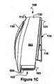
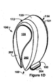
図1A、図1B、図1Cおよび図1Dは、提案された解決の第1の実施形態による歯ブラシホルダー100を示す。
Toothbrush holder FIGS. 1A, 1B, 1C and 1D show a
提案された解決の第1の実施形態によれば、歯ブラシホルダー100は概して歯ブラシホルダー筐体110、またはハウジング、および歯ブラシクランプ部材200を含む。ハウジング110は歯ブラシホルダーに挿入された歯ブラシを保護するように構成され、好ましくは、ハウジング110は防滴筐体である。歯ブラシを通過させるために筐体110の底部に開口102が提供される。
According to a first embodiment of the proposed solution, the
第1の実装形態によれば、歯ブラシホルダー筐体110は正面カバー112および背板114を含む。図1Bは筐体110の正面カバー112を示す一方で、図1A、図1Cおよび図1Dは正面カバー112および背板114の両方を示し、正面カバー112は背板114に嵌合されている。例えば図3A、図3B、図3Cおよび図3Dを参照すると、正面カバー112と背板114を一緒にスナップ嵌めするように構成することができる。しかし正面カバー112と背板114を一緒に接着することもできる。好ましくは、例えば食洗機または正面カバー112が製造された材料に適合する衛生のあらゆる他の手段で洗浄するために、正面カバー112は取外し可能である。本発明を限定するものではないが、図1Aおよび図1Dに示されたように、正面カバー112は、さらに例えば液滴を防ぐために背板114の露出をできる限り少なく構成される。正面カバー112の底部は筐体開口102を画定する部分を形成する。本発明を限定するものではないが、図1Cは垂直に対してある角度116で嵌合する正面カバー112および背板114を示し、この第1の実施形態では背板114は概ね楔形状を有する。さらにこの第1の実施形態の正面カバー112の他の詳細の説明を、図8A、図8B、図8C、図8D、図9A、図9B、図9C、図9Dおよび図9Eを参照して以下に示す。正確には、本発明は対称な歯ブラシホルダー筐体110に限定されず、対称な歯ブラシホルダー筐体110の実装形態は、本明細書の説明を簡単にするために示されたに過ぎない。
According to the first implementation, the
背板114に戻ると、図2A、図2B、図2C、図2Dおよび図2Eは、提案された解決の第1の実施形態の第1の実装形態による背板114を示す。背板114は平坦な中間部118を含む概ね平坦な形状を有する。背板114は実質的に垂直な壁に、好ましくは例えばタイル上に接着剤で半永久的に、またはネジなどの締結具(図示せず)で木材上に永久的に(図10A、図10B、図10Fおよび図10G参照)取り付けられるように構成される。使い捨て可能な歯ブラシホルダー100は吸盤締結具を利用することができる。本発明を限定するものではないが、図2Dは、接着剤または両面テープを付けることができる平坦な中間部118における楕円形の中央領域を示す。
Returning to the
第1の実施形態のこの実装形態の背板114は、正面カバー112とのスナップ嵌めを提供する際に部分的に利用される周縁部121を有し、正面カバー112は、背板114の露出を図1A、図1Cおよび図1Dに示されたよりさらに低減する(図示せず)背面カバー114の長円形の周辺縁部の周囲に延在するように構成されたスナップタブを有する。提案された解決の使い捨て可能な実装形態に対して、正面カバー112を背板114の長円形の周辺リム121の周囲で背板114に接着することができる。背板114の周辺縁部121の底部は筐体開口102を画定する部分を形成する。本発明は不連続の周辺縁部121に限定されず、図3A、図3Cおよび図3Dは全体的に卵形の周辺縁部121を示す。
背板114は、さらに歯ブラシホルダー100の歯ブラシ把持要素200を係合するように構成される。提案された解決の第1の実施形態の第1の実装形態によれば、示されたように歯ブラシホルダー筐体110に対して前方に、また背板114から離れて延在する1対の実質的に水平な支持(底部)タブ260が、歯ブラシ把持要素200をその上に置くために提供される。本発明は1対の支持タブ260または水平な支持タブ260に限定されない。厳密には説明を簡単にするために1対の対称な支持タブ260が示されているに過ぎず、歯ブラシ把持要素200を参照して以下に説明されるように単一のタブ260も充分に可能である。好ましくは、背板114は図2Cに示されたように側部から見たときに楔形状(166)を有し、これは背板114の周辺縁部121を背板114の中間部118に対してある角度116で、また背板114を取り付ける壁に対してある角度116で延在することにより配向させる。したがって支持タブ260は壁に対して実質的に垂直であるか、または背板114の周辺嵌合縁部121の平面に実質的に垂直であることが可能である。厳密には背板114の周辺嵌合縁部121は平面内にある必要はなく、支持タブ260を壁に向かって傾斜させることができる。
The
提案された解決の第1の実施形態の第2の実装形態により、図3A、図3B、図3Cおよび図3Dは、歯ブラシ把持要素を係合するためのスナップ嵌めおよび異なる構成で正面カバー112を係合するためのスナップタブ270を含む背板114を示す。
According to a second implementation of the first embodiment of the proposed solution, FIGS. 3A, 3B, 3C and 3D show the
第1の実施形態の第2の実装形態によれば、正面カバー112と背板114との間のスナップ嵌めは、背板114の周辺縁部121の概ね周囲に必ずしも連続しない、背板114から前方に延びる短壁272によって提供される。この第2の実装形態における壁272によりスナップ嵌め結合を向上させることができ、この壁は弾性材料、例えば適切な高分子から製造することができる。壁272は、壁272の非屈曲部272と短壁272内に提供された屈曲スナップタブ270との間に切欠き274(例えば図10E、図10Fおよび図10Gに示されている)を備えて不連続であることが可能である。スナップタブ270は正面カバー112を係合するためのフック要素を含むことができる。
According to a second implementation of the first embodiment, a snap fit between the
歯ブラシが把持要素200によって保持されている間、歯ブラシは筐体開口102に挿入されており、筐体開口102と把持要素200との間の位置合わせの一部の形は、すべての実施形態に必ずしも必要とされないが有益であることが可能であることに留意されたい。第1の実施形態の第2の実装形態によれば、歯ブラシ把持要素200に対して支持および位置合わせ(260)が提供される。1対の支持タブ260が提供されるが、支持タブ260は図10A及び12Aにおいて互いに向かって傾斜して示されていることに留意されたい。本発明を限定するものではないが、支持タブ260間の角度は把持要素200を把持構成に戻す方法を提供し、歯ブラシの把持を高め、把持要素200またはそのあらゆる組合せを位置合わせすることができる。
While the toothbrush is held by the
別の対の上部支持タブ280は、実質的に背板114の先端に示されており、さらに把持要素200に対する支持および位置合わせを提供するように構成される。本発明を限定するものではないが、互いから離れて傾斜する上部タブ280によって、かつ/または切込み282の中に延在する適切に構成された把持要素200、例えば切込み282の中に延在する把持要素200上の突起284のための上部タブの間の切込み282によって位置合わせを提供することができる。
Another pair of
必須ではないが、左右のスナップタブ270は短壁272を越えて延在し、底部支持タブ260の周囲に位置付けられて示されており、例えば底部支持タブ260の強度を高め、かつ/またはさらに歯ブラシ把持要素200に対して側部の位置合わせを提供する。
Although not required, the left and
正面筐体がなく背板114と歯ブラシ把持部200の組合せを使用できる、別の任意的なクラウンタブ290が示されている。歯ブラシが歯ブラシホルダー100に挿入されている間、クラウンタブ290は、単独でもまたは正面カバー112との組合せでも反力を提供する。またクラウンタブ290は、スナップタブ270を構成する際にも利用される材料偏差に対抗することもできる。クラウンタブ290が存在しないときは、歯ブラシが歯ブラシホルダー100に挿入されている間、正面カバー112または短壁272が反力を提供する。厳密には、クラウンタブ290はクラウン形状である必要はない。
Another
提案された解決の第1の実施形態の第2の実装形態により、図4A、図4B、図4C、図4Dおよび図4Eは背板114と歯ブラシ把持要素200との組合せを示す。把持要素200は、底部支持タブ260、上部支持タブ280および任意的にクラウンタブ290を介して背板114と協働する。1対の把持要素タブ210は背板114の底部支持タブ260上に着座する。示された把持要素200は、本発明をこれに限定するものではないが、上部支持タブ280間の切込み282と協働するガイド284を含む。示されたように、背板114と歯ブラシ把持要素200の組合せにより、正面カバー112なしに歯ブラシを保持できるように協働することができる。
According to a second implementation of the first embodiment of the proposed solution, FIGS. 4A, 4B, 4C, 4D and 4E show the combination of the
好ましくは、歯ブラシ把持要素200はその型締めにより歯ブラシを機械的に係合するように構成される。その組合せを使用する1つの方法によれば、上部支持タブ280およびクラウンタブ290は、把持要素200を例えばスナップフックまたは別の分離可能な係合具を介して強固に係合し、歯ブラシはクラウンタブ290(および/または存在する場合は壁272)に対して把持要素200に挿入され、支持タブ280/260に対して把持要素200から引き抜かれる。組合せを使用する別の方法によれば、上部支持タブ280は把持要素200を掛けるフックとして作動し、把持要素200は、歯ブラシを挿入している間およびそこから歯ブラシを引き抜いている間は背板114から取り外され、その後戻される。本明細書に記載された「カバー本体」への言及は、歯ブラシホルダー筐体110を全体として含むことが意図される。
Preferably, the
厳密には、歯ブラシ把持要素200は歯ブラシ、少なくとも歯ブラシ頭部を係合し、衛生のために筐体から取り外し可能であることが好ましい。厳密には、本発明は取り外し可能な歯ブラシ把持要素200の利用に限定されず、使い捨て可能な歯ブラシホルダー100においては、歯ブラシ把持要素200は取り外し可能でなくてもよい。使い捨て可能な歯ブラシホルダー100は、ホテル業界または病院環境において使用されてもよい。図4Cは、把持要素200と組み合わせた背板114の傾斜部(116)を最もよく示す。背板114の傾斜部(116)は、正面カバー112を利用しないときに把持要素200を壁に向かわせ、かつ/または歯ブラシの柄が歯ブラシ把持部200を(および歯ブラシホルダー100を全体として)壁から離さないように、挿入されたときに壁に向かって湾曲した柄を有する歯ブラシが占める働きをすることができる。
Strictly speaking, the
正面カバー112とともに使用して、背板114と把持要素200の組合せは、歯ブラシの移動経路を筐体開口102と実質的に位置合わせするように構成される。図4Bは背板114の底部周辺縁部121と位置合わせされた把持要素200の端部204を最もよく示している。
For use with the
クリップ
図5A、図5B、図5C、図5D、図5Fおよび図5Gは、提案された解決の第1の実施形態による歯ブラシ把持要素200の第1の実装形態を示す。歯ブラシ把持要素200は、クリップ(200)および例えば上に記載されたような任意的な位置合わせ要素210/284を含む。厳密には、突起284は一部の実装形態に存在するに過ぎない。上に記載されたように、突起284の存在は上部支持タブ280が任意的である際に使用することを示唆するものではない。説明を記憶に留めるために、「クリップ」への言及は歯ブラシ把持要素200を含む。
Clips FIGS. 5A, 5B, 5C, 5D, 5F and 5G show a first implementation of a
クリップ200は、互いに向かって付勢された2つの対向する把持部材202を含み、少なくとも歯ブラシ頭部を係合するために協働する。クリップ200は、歯ブラシホルダー100内に歯ブラシを保持するために歯ブラシ頭部および歯ブラシ頸部の少なくとも1つを把持するように構成される。把持部材202は互いに対して付勢されたものとすることができ、弾性材料、例えば高分子に限定されない弾力材料から製造される。また金属クリップ200も必要な弾性把持を提供することができる。製造の観点から、高分子をクリップ200の形に射出成形できる。本発明は1つの製造技法に限定されない。
一部の実施形態では、歯ブラシは重力の垂直抗力に抵抗して歯ブラシホルダー内に保持される。 In some embodiments, the toothbrush is held in a toothbrush holder against the normal force of gravity.
把持部材202は、歯ブラシ頭部の挿入、またその逆に引き抜きによって分離される。
The gripping
好ましくは、歯ブラシ全体と歯ブラシホルダー100全体との間の係合領域は最小にされる。好ましくは、係合部は把持部材202の端部204のために低減される。
Preferably, the engagement area between the entire toothbrush and the
第1のクリップ実装形態に関して、ローラ206を利用する把持部材の端部204が主に図4A、図4B、図4C、図4D、図4E、図5A、図5B、図5C、図5D、図5E、図5Fおよび図5Gに示されている。各ローラ206は、対応する枢動軸の周囲を移動するように構成され、クリップ200と歯ブラシとの間に機械的な回転係合を提供する。歯ブラシ頭部は、歯ブラシを把持部にスナップ止めするまでローラ206の上を摺動することができる。一部の実装形態では、ローラ206が歯ブラシ頸部を係合するときに歯ブラシを把持部にスナップ止めする。
Regarding the first clip mounting configuration, the
厳密には、本発明は両方の把持部材202が弾性であるものに限定されない。単一の弾性把持部材202が堅固な把持部材(202)に当たると、機能するであろう。
Strictly, the present invention is not limited to those in which both gripping
好ましくは、ローラ206は歯ブラシ頭部および/または頸部のためにチャネル状ガイド208を形成する。例えばローラ206はチャネル状ガイド208を画定する周辺切欠き212を含むことができる。
Preferably, the
周辺切欠き212は(単独であっても組合せであっても)歯ブラシホルダー100の底部における凹型の窪みを歯ブラシ頭部に提示し、把持部材202の間のチャネル状ガイド208の中に導く。
A
好ましくは、クリップ200は該端部204から歯ブラシの毛の所望の配向にクリップ端部204から概ね離れて延在する、1対のクリップタブ210を含む。図4A、図4B、図4C、図4D、図4E、図5A、図5B、図5C、図5D、図5E、図5F、図5G(および図6A、図6B、図6C、図6D、図6E、図6F、図6G)は、歯ブラシの毛が壁に向いた状態で歯ブラシを挿入するために、歯ブラシホルダー100の背面に向かって延在するクリップタブ210を示す。クリップタブ210はクリップタブの間に切込み214を形成する。切込み214によりクリップタブ210の間を歯ブラシの毛が通過することができる。
Preferably, the
提案された解決によれば、クリップタブ210は、歯ブラシ頭部をクリップ200に挿入しないように構成される一方で、歯ブラシ頭部をクリップローラ206の間に挿入することができ、歯ブラシを特定の配向に向ける。図4A、図4B、図4C、図4D、図4E、図5A、図5B、図5C、図5D、図5E、図5F、図5G(および図6A、図6B、図6C、図6D、図6E、図6F、図6G)は、クリップ200の中への歯ブラシ頭部の移動方向に概ね垂直なクリップタブ210を示すが、本発明は歯ブラシの移動の阻止に限定されない。別法として、挿入される歯ブラシ頭部に凸状の全面を提示して歯ブラシ頭部を偏向させるようにクリップタブ210を構成することができる。その上、偏向を提供するために歯ブラシ頭部の移動方向に対して、傾斜した、または歪んだ(図11A、図11B、図11Eおよび図11F)同一平面にクリップタブ210が存在することができる。
According to the proposed solution, the
厳密には、本発明は2つのローラ206の使用に限定されない。歯ブラシ頸部を係合する必要がない3つ以上のローラ206を利用することができる(図示せず)。その他の把持部材に当たる単一のローラ206も機能するはずである。ローラ206を利用することにより、頭部の側部がゴム引きされた歯ブラシを使用することができる。
Strictly speaking, the present invention is not limited to the use of two
図6A、図6B、図6C、図6D、図6E、図6Fおよび図6Gは、提案された解決の第1の実施形態による歯ブラシ把持要素200の第2の実装形態を示す。構造および要素の説明を簡潔にするために、第1の歯ブラシ把持要素200の実装形態と同様のものは繰り返さない。第2のクリップの実装形態200は本来ローラ206を利用せず、代わりに把持部材端部204はそれらの間にチャネル状ガイド208を画定する対向する切欠き212を含む。切欠き212は、機械的係合の摺動を介して少なくとも歯ブラシ頭部を係合するように構成される。さらに切欠き212は互いから広げられて、チャネル状ガイド208の中に導く凹型の窪みを歯ブラシ頭部の挿入に提示する。ローラ206、切欠き212の数の変形形態、および把持部材202の材料弾性のように、類似の変形形態を利用できる。
6A, 6B, 6C, 6D, 6E, 6F and 6G show a second implementation of the
歯ブラシの毛を背板214から離間するために切欠き212と組み合わせて歯ブラシの毛を超えて延在するタブ210の先端が、図5F、図5C、図5D、図6C、図6Dおよび図6Gに最もよく示されている。
The tips of
本発明は、タブ210の先端を介して背板114から歯ブラシの毛を離間することに限定されない。図4A、図4B、図4C、図4D、図4E、図5A、図5B、図5C、図5D、図5E、図5F、図5G、図6A、図6B、図6C、図6D、図6E、図6Fおよび図6Gは、背板114から歯ブラシの毛を離間するために背板114に向かって歯ブラシの毛の方向に偏向され延在するクリップ200本体を示す。
The present invention is not limited to separating the toothbrush bristles from the
厳密には、本発明は、クリップタブ210の使用を、歯ブラシを歯ブラシホルダー100に配向することに限定されない。図7A、図7B、図7Cおよび図7Dは、提案された解決の第1の実施形態による歯ブラシ把持要素200の第3の実装形態を示す。構造および要素の説明を簡潔にするために、第1の歯ブラシ把持要素200の実装形態と同様のものは繰り返さない。
Strictly, the present invention is not limited to the use of the
歯ブラシの配向は1対の肩部216を介して提供される。把持部材202は端部204で広がるように形状され、歯ブラシを挿入するために凹型の窪みを提示する一方で、肩部216は歯ブラシの毛のみがその間を通過できる制限通路を提供するように構成される。肩部216も半径は狭いが広げることができるか、または歯ブラシ頭部を挿入するために縁部を提示することさえもできる一方で、歯ブラシの毛がその間を通過する切込み(214)を画定し、クリップ200に対して歯ブラシの配向を促す。肩部216はチャネル状ガイド208を画定する把持部材202に実質的に平行に延在する縁部を含むことができ、かつ/または切込みを画定する把持部材に実質的に垂直に延在する別の縁部を含むことができる。歯ブラシの毛を背板114から離間するために、肩部216は歯ブラシの毛の長さより大きい背板114に向かって延在する。
Toothbrush orientation is provided through a pair of
特にこの実装形態では、突起の位置合わせ要素284は、背板114内に対応する開口(図示せず)を係合するように構成された2つの隆起284に置換される。また背板114は底部支持タブ260を必要としないであろう。
In particular, in this implementation, the
正面カバー
正面カバー112の説明に戻ると、正面カバーは必ずしも単片ではない。図8A、図8B、図8Cおよび図8Dは、接着剤を介して背板114を係合するように構成された、必ずしもそうではないが概ね不透明である第1の正面カバー要素120を示す。好ましくは、正面カバー112は図13B、図13D、図13E、および図13Fに示されるように、本明細書で上述されたようなスナップ嵌め係合270を介して背板114を係合する。
Front Cover Returning to the description of the
好ましくは、正面カバー112は図8B、図8Cおよび図8Dに最もよく示された広がった側部103を含み、歯ブラシ頭部を歯ブラシホルダー100に挿入するための誘導をさらに提供する。
Preferably, the
正面カバー112には歯ブラシホルダー筐体100の中を見る窓130を提供することができる。図9A、図9B、図9C、図9Dおよび図9Eは第2の正面カバー要素130、すなわち窓を示す。例えば正面カバー窓130は涙滴型であることが可能であり、第1の正面カバー要素120の中にスナップ嵌めを適合された形状および構成の特徴を有することができる。
The
好ましい実施形態
提案された解決の第1の実施形態の第4の実装形態により、図10A、図10B、図10C、図10D、図10E、図10Fおよび図10Gは再利用可能な衛生的な背板114を示す。図3A、図3B、図3Cおよび図3Dに示された背板114と共通する特徴は繰り返さない。
Preferred Embodiment According to a fourth implementation of the first embodiment of the proposed solution, FIGS. 10A, 10B, 10C, 10D, 10E, 10F, and 10G are reusable hygienic backs. A
背板114は遮断された周辺壁272を備えた全体が卵形状を有する。例えば高分子などの材料選択および/または自在に延びる材料厚さにより、正面カバー112を係合する際に、スナップタブ270に遮断された周辺壁272より多く屈曲を提供するように構成することができる。正面カバー112を係合する際に遮断された周辺壁272に向上した剛性を提供するように構成することができるのに対して、スナップタブ270は背板114に向かって正面カバー112を引いて閉じる作用をする。
The
図10Bに示されたように、両面テープまたは接着剤を取り付けるための長円領域118が、背板114の背面に提供され、さらに洗面所の壁との係合を確実にするために締結具または吸盤(図示せず)を受け取り係合するために、図10A、図10B、図10Fおよび図10Gに最もよく示されているように強化された開口が提供される。
As shown in FIG. 10B, an
第4の実装形態によれば、支持タブ270は強化される。底部支持タブ260は、図10A、図10Fおよび図10Gに最もよく見られるように周壁272と一体化される。図10A、図10Dおよび図10Gに最もよく示されているように、上部支持タブ280は突起を介して強化される。
According to the fourth implementation, the
図11A、図11B、図11C、図11D、図11E、図11Fおよび図11Gは再利用可能な衛生的な歯ブラシ把持要素200またはクランプ200を示す。図5A、図5B、図5C、図5D、図5E、図5Fおよび図5Gに示されたクランプ200と共通する特徴は繰り返さない。
11A, 11B, 11C, 11D, 11E, 11F, and 11G illustrate a reusable sanitary
クランプ200は、図11B、図11Eおよび図11Fに最もよく示されている対応する突起によって強化された1対の歯ブラシ把持要素タブ210を利用する。クランプタブ210は図11A、図11B、図11Eおよび図11Fに示されたように同一面にないことに留意されたい。
図12A、図12B、図12C、図12Dおよび図12Eは、組み合わされた再利用可能な衛生的な歯ブラシ把持要素200と背板114の組合せを示す。図4A、図4B、図4C、図4Dおよび図4Eに示された組合せと共通する特徴は繰り返さない。
12A, 12B, 12C, 12D and 12E show a combined reusable sanitary
図13A、図13B、図13C、図13D、図13Eおよび図13Fは、再利用可能な衛生的な正面カバー112/120を示す。図8A、図8B、図8Cおよび図8Dに示された正面カバー120と共通する特徴は繰り返さない。
13A, 13B, 13C, 13D, 13E and 13F show a reusable sanitary
正面カバー120は広がった横壁(図13A、図13Bおよび図13E)がない一方で、窓を形成する2つの側部の間に強化する橋140が提供される。また図13A、図13B、図13Cおよび図13Fに最もよく示されている架橋140は、本明細書の以下に説明されるように、窓130を固定する際に関与するように構成されることが可能である。多数の強化する突起は図13Bおよび図13Eに見られ、ハウジング110の底部開口の周囲の剛性を向上させる。背板114のスナップ嵌めタブ270を機械的に係合するためのスナップ嵌め開口は、図13B、図13D、図13Eおよび図13Fに最もよく示されている。スナップ嵌めタブ270は、図13B、図13Eおよび図13Fに最もよく示されたチャネル172によって誘導される。
The
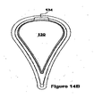
図14A、図14B、図14C、図14D、図14Eおよび図14Fは再利用可能な衛生的な正面カバー窓130を示す。図9A、図9B、図9C、図9Dおよび図9Eに示された正面カバー窓130と共通する特徴は繰り返さない。
14A, 14B, 14C, 14D, 14E, and 14F illustrate a sanitary
特に正面カバー窓130は、橋140を係合するための底部フック132および正面カバー120の上部に係合するための上部スナップ嵌めの隆起134を利用する。フック132および隆起134のどちらも、正面カバー120とスナップ嵌め係合する際に正面カバー窓130を解除可能に保持するように作用する。
In particular, the
一体型の歯ブラシホルダー
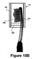
提案された解決の第2の実施形態による、一体型の歯ブラシホルダー筐体110は図15Aおよび15Bに示されている。歯ブラシホルダー100は壁に取り付けられるように構成された概ね平坦な背板114を含む。
Integrated Toothbrush Holder An integrated
正面カバー120は、概ねU字形の断面を有する背板114と一体化する、背板114に装着可能である、背板114にしっかりと接着することなどが可能である。クリップの対向する弾性の把持部材202は歯ブラシホルダー筐体110の側壁を形成する。
The
好ましくは、把持部材202は歯ブラシを歯ブラシハウジング筐体110の中に誘導するために広がった端部(103)204を有する。
Preferably, the gripping
好ましくは、吸盤締結具または適切な取り外し可能な締結具が提供され、歯ブラシホルダー筐体110は移動するように適合される。
Preferably, a suction cup fastener or suitable removable fastener is provided and the
二重ローラ
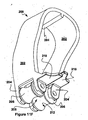
提案された解決の第3の実施形態による、別の歯ブラシホルダークリップ200が図16A、図16B、図16C、図16D、図16Eおよび図16Fに示されている。歯ブラシホルダークリップ200は、歯ブラシを歯ブラシホルダークリップに、したがって歯ブラシホルダー筐体110内の延長により2配向、すなわち、歯ブラシの毛が前方に面するか、または歯ブラシの毛が背を向けるかのいずれかの配向で挿入できるように構成される二重ローラ206を含む。図5C、図5D、図5E、図5Fおよび図5Gに示されたようなクリップタブ(210)は利用されない一方で、第2の対のローラ206は歯ブラシホルダークリップ200の外側の構造、表面、対象などと接触しようとする歯ブラシの毛を、したがって歯ブラシ頭部をいずれかの配向に離間させる。歯ブラシホルダークリップ200の対向する弾性の把持部材202は、対応する歯ブラシホルダー筐体110の側壁を形成することができる。一部の実装形態では、歯ブラシ筐体110は、歯ブラシホルダークリップ200内の歯ブラシの位置付けの遊びを低減するために、特定の形状を有する歯ブラシとより良好に協働するように構成される。示された歯ブラシホルダークリップ200は「A」字形を有するように示されており、これはその中における歯ブラシの位置付けの遊びの低減を提供することができる。例えば上に記載されたような任意的な背板(114)および任意的な正面カバー(112)の他の詳細は、簡潔にするために割愛する。
Double Roller Another
本発明はその好ましい実施形態を参照して示され説明されているが、添付の特許請求の範囲に定義されたように、本発明の精神および範囲から逸脱することなく、形および詳細の様々な変更を行うことができることが当業者には認識されよう。 Although the invention has been shown and described with reference to preferred embodiments thereof, it is understood that a variety of forms and details may be used without departing from the spirit and scope of the invention as defined in the appended claims. Those skilled in the art will recognize that changes can be made.
Claims (5)
前記歯ブラシホルダー(100)が:
互いに向かって付勢される2つの対向する把持部材(202)を有するクリップ(200)であって、前記把持部材は、前記頭部の挿入によって分離されるように、対向するローラ(206)を備える端部(204)を有し、前記頭部は、前記ローラ(206)が前記頸部を保持できるまで前記ローラ(206)の上を摺動できる、クリップ(200)と、
前記歯ブラシが前記クリップ(200)によって保持されるときに前記毛を保護するように適合されたカバー本体(110)と、
を備え、
前記ローラ(206)それぞれが、その側部により前記歯ブラシの前記頭部に回転係合するように構成されており、かつ
前記ローラ(206)それぞれが、前記歯ブラシの前記頭部を前記把持部材(202)間で導くために、前記ローラの回転軸周りに全周に亘ってくびれた形状を有することによって、前記歯ブラシの前記頭部に対する凹面状の窪みを呈する、歯ブラシホルダー(100)。 A toothbrush holder (100) for a toothbrush having a head, bristles extending from the head, a handle, and a neck between the head and the handle,
The toothbrush holder (100) is:
A clip (200) having two opposing gripping members (202) biased towards each other, the gripping members having opposing rollers (206) so that they are separated by insertion of the head. A clip (200) having an end (204) comprising, the head being slidable on the roller (206) until the roller (206) can hold the neck;
A cover body (110) adapted to protect the bristles when the toothbrush is held by the clip (200);
With
Each of the rollers (206) is configured to be rotationally engaged with the head of the toothbrush by a side portion thereof, and each of the rollers (206) holds the head of the toothbrush with the gripping member ( 202) a toothbrush holder (100) that has a constricted shape around the rotation axis of the roller over the entire circumference to guide it between the heads of the toothbrush.
両方の前記ローラ(206)は、前記歯ブラシの前記頸部が前記クリップ(200)内で解除可能に把持されるようにチャネル状ガイド(208)を形成することを特徴とする請求項1に記載の歯ブラシホルダー(100)。 At least one of the rollers is configured to rotate about a corresponding pivot that provides rotational engagement between the roller (206) and the toothbrush;
Both said rollers (206) form a channel-like guide (208) such that the neck of the toothbrush is releasably gripped within the clip (200). Toothbrush holder (100).
前記ローラ(206)の少なくとも1つは、対応する前記ローラ(206)に対して前記把持力を提供する弾性材料を含む
ことを特徴とする請求項1〜3のいずれか1項に記載の歯ブラシホルダー(100)。 At least one of the gripping members (202) comprises an elastic material that provides a gripping force against the corresponding opposing gripping member (202); or
The toothbrush according to any one of claims 1 to 3, wherein at least one of the rollers (206) comprises an elastic material that provides the gripping force to the corresponding roller (206). Holder (100).
Applications Claiming Priority (2)
| Application Number | Priority Date | Filing Date | Title |
|---|---|---|---|
| US201261729115P | 2012-11-21 | 2012-11-21 | |
| PCT/CA2013/050733 WO2014078953A1 (en) | 2012-11-21 | 2013-09-26 | Toothbrush holder apparatus |
Publications (2)
| Publication Number | Publication Date |
|---|---|
| JP2016533854A JP2016533854A (en) | 2016-11-04 |
| JP6471167B2 true JP6471167B2 (en) | 2019-02-13 |
Family
ID=50775350
Family Applications (1)
| Application Number | Title | Priority Date | Filing Date |
|---|---|---|---|
| JP2016543273A Active JP6471167B2 (en) | 2012-11-21 | 2013-09-26 | Toothbrush holder device |
Country Status (12)
| Country | Link |
|---|---|
| US (2) | US9364076B2 (en) |
| EP (1) | EP2903485B1 (en) |
| JP (1) | JP6471167B2 (en) |
| KR (1) | KR102197058B1 (en) |
| CN (1) | CN105578932B (en) |
| AU (1) | AU2013350279B2 (en) |
| BR (1) | BR112016006420B1 (en) |
| CA (2) | CA2887992C (en) |
| ES (1) | ES2641540T3 (en) |
| MX (1) | MX368080B (en) |
| RU (1) | RU2644104C2 (en) |
| WO (1) | WO2014078953A1 (en) |
Families Citing this family (8)
| Publication number | Priority date | Publication date | Assignee | Title |
|---|---|---|---|---|
| CA2887522A1 (en) * | 2015-04-11 | 2016-10-11 | Maxor Inc. | Toothbrush holder with bristle treatment liquid dispenser |
| CA2887531A1 (en) * | 2015-04-13 | 2016-10-13 | Maxor Inc. | Toothbrush holder |
| USD841337S1 (en) | 2015-05-12 | 2019-02-26 | Maxor Inc. | Toothbrush holder |
| US10058219B2 (en) * | 2016-01-07 | 2018-08-28 | Diana M. Collins | Horizontal and vertical toothbrush holder suitable for the application of toothpaste |
| US9951821B1 (en) | 2017-01-11 | 2018-04-24 | Crossford International, Llc | Drive shaft coupling |
| CN106983415B (en) * | 2017-05-27 | 2019-08-16 | 唐佳怡 | Intelligent toothbrush rack |
| USD901900S1 (en) * | 2019-01-23 | 2020-11-17 | Ranir, Llc | Cover for a portion of a toothbrush |
| KR102559236B1 (en) * | 2022-11-28 | 2023-07-24 | 정철균 | Toothbrush Sterilizer |
Family Cites Families (25)
| Publication number | Priority date | Publication date | Assignee | Title |
|---|---|---|---|---|
| US1117491A (en) * | 1913-11-07 | 1914-11-17 | Elias Hornung | Umbrella-stand. |
| US1174185A (en) * | 1915-11-08 | 1916-03-07 | Brunswick Balke Collender Co | Billiard-cue rack. |
| US1544694A (en) * | 1922-12-16 | 1925-07-07 | Immanuel G Speidel | Toothbrush holder |
| US1911781A (en) * | 1932-03-18 | 1933-05-30 | Jr Oliver P Wolfe | Support and holder for brooms, mops, and the like |
| US2162283A (en) * | 1936-03-06 | 1939-06-13 | Oshman Benjamin | Tooth brush retainer |
| US2275549A (en) * | 1940-03-11 | 1942-03-10 | Oshman Benjamin | Toothbrush retainer |
| US2309116A (en) * | 1940-08-03 | 1943-01-26 | Gunnar B Hylen | Toothbrush holder |
| US2531066A (en) * | 1945-07-26 | 1950-11-21 | John J Lynch | Spring-hinged two-part receptacle |
| US2600345A (en) * | 1950-08-08 | 1952-06-10 | Francis A Venditti | Toothbrush and article holder |
| US2937910A (en) * | 1958-06-25 | 1960-05-24 | Sam J Randa | Sanitary toothbrush holder |
| US3138414A (en) * | 1961-11-16 | 1964-06-23 | Pollo Michael A La | Sanitary rack for toothbrushes and dentifrice |
| US3977743A (en) * | 1975-09-29 | 1976-08-31 | John Madison Harris | Combination wall-mounted toothbrush holder and carrying case |
| GB1601092A (en) | 1978-05-31 | 1981-10-21 | Sanderson L W | Toothbrush holder |
| US4396238A (en) | 1980-02-07 | 1983-08-02 | Pervisa S.A. | Toothbrush holder |
| JPS6342867Y2 (en) * | 1985-04-10 | 1988-11-09 | ||
| US4884311A (en) * | 1988-05-27 | 1989-12-05 | Harbert S Gergory | Dental appliance |
| IT8921221A0 (en) * | 1989-07-18 | 1989-07-18 | Idrogas Di Edmondo Pancotti E | IMPROVED TOOTHBRUSH HOLDER. |
| US5332107A (en) | 1991-07-29 | 1994-07-26 | Camps Limited | Dental care center |
| DE4411347A1 (en) * | 1994-03-31 | 1995-10-05 | Matthias Dr Heister | Toothbrush holder with bristle alignment |
| FI970616A0 (en) * | 1997-02-14 | 1997-02-14 | Puurunen Juha Pekka | Tandbortstaell |
| CN2448252Y (en) * | 2000-11-07 | 2001-09-19 | 阳小军 | Plug-in wall hanging type toothbrush disinfecting dryer |
| US6776296B2 (en) * | 2001-11-13 | 2004-08-17 | Anthony J Herren | Toothbrush holder |
| US7185796B2 (en) * | 2003-10-08 | 2007-03-06 | Armament Systems & Procedures, Inc. | Baton scabbard with roller clamp retention |
| US20060032828A1 (en) * | 2004-05-29 | 2006-02-16 | Chiu Sai Y | Holder for organization and storage |
| CN202941986U (en) * | 2012-11-27 | 2013-05-22 | 李作贤 | Suction-hanging type dustproof sanitary tooth brush case |
-
2013
- 2013-09-26 RU RU2016110776A patent/RU2644104C2/en active
- 2013-09-26 CA CA2887992A patent/CA2887992C/en active Active
- 2013-09-26 EP EP13856600.5A patent/EP2903485B1/en active Active
- 2013-09-26 CN CN201380079839.2A patent/CN105578932B/en active Active
- 2013-09-26 KR KR1020167008075A patent/KR102197058B1/en active IP Right Grant
- 2013-09-26 AU AU2013350279A patent/AU2013350279B2/en active Active
- 2013-09-26 CA CA2921888A patent/CA2921888C/en active Active
- 2013-09-26 BR BR112016006420-8A patent/BR112016006420B1/en active IP Right Grant
- 2013-09-26 JP JP2016543273A patent/JP6471167B2/en active Active
- 2013-09-26 WO PCT/CA2013/050733 patent/WO2014078953A1/en active Application Filing
- 2013-09-26 MX MX2016003175A patent/MX368080B/en active IP Right Grant
- 2013-09-26 ES ES13856600.5T patent/ES2641540T3/en active Active
-
2015
- 2015-05-13 US US14/710,957 patent/US9364076B2/en active Active
-
2016
- 2016-05-17 US US15/156,852 patent/US9596960B2/en active Active
Also Published As
| Publication number | Publication date |
|---|---|
| CA2921888C (en) | 2020-10-27 |
| US20160256013A1 (en) | 2016-09-08 |
| EP2903485B1 (en) | 2017-06-28 |
| US20150320264A1 (en) | 2015-11-12 |
| BR112016006420A8 (en) | 2017-10-24 |
| EP2903485A1 (en) | 2015-08-12 |
| CA2921888A1 (en) | 2014-05-30 |
| CN105578932A (en) | 2016-05-11 |
| JP2016533854A (en) | 2016-11-04 |
| RU2644104C2 (en) | 2018-02-07 |
| MX368080B (en) | 2019-09-18 |
| RU2016110776A (en) | 2017-10-30 |
| KR102197058B1 (en) | 2020-12-30 |
| WO2014078953A1 (en) | 2014-05-30 |
| CN105578932B (en) | 2017-10-13 |
| EP2903485A4 (en) | 2016-03-23 |
| ES2641540T3 (en) | 2017-11-10 |
| BR112016006420B1 (en) | 2021-08-17 |
| MX2016003175A (en) | 2016-11-29 |
| US9596960B2 (en) | 2017-03-21 |
| CA2887992C (en) | 2016-06-07 |
| US9364076B2 (en) | 2016-06-14 |
| CA2887992A1 (en) | 2014-05-30 |
| AU2013350279B2 (en) | 2019-04-18 |
| KR20160052597A (en) | 2016-05-12 |
| BR112016006420A2 (en) | 2017-09-05 |
| AU2013350279A1 (en) | 2016-04-07 |
Similar Documents
| Publication | Publication Date | Title |
|---|---|---|
| JP6471167B2 (en) | Toothbrush holder device | |
| EP1938738B1 (en) | Cleaning tool | |
| JP7451692B2 (en) | Mounting part of replacement head for electric toothbrush | |
| US20060207623A1 (en) | Self-cleaning hair brush | |
| US20160296003A1 (en) | Oral Care Implement and Oral Care System | |
| JP2012090947A (en) | Handle with end cap for cleaning tool | |
| JP2010268973A (en) | Handy mop | |
| US20180084901A1 (en) | Toothbrush holder with bristle treatment liquid dispenser | |
| EP3434167A1 (en) | Cleaning tool | |
| KR102155902B1 (en) | Accessories mounting device | |
| US7537115B2 (en) | Display apparatus for implements with handles and working ends | |
| KR102386940B1 (en) | Auxiliary grip for golf putter | |
| KR200494532Y1 (en) | Multi-purpose mounting plate, handle fixing member, and multi-purpose mounting module having the same | |
| JP5249867B2 (en) | Cleaning tool | |
| JP4562181B2 (en) | Sponge sandwich | |
| EP2061565A2 (en) | A golf club cleaning device and a coupling member | |
| JP2023140469A (en) | Rotation suppression tool and cleaning jig with rotation suppression tool | |
| IE20070662U1 (en) | A golf club cleaning device and a coupling member | |
| IES85199Y1 (en) | A golf club cleaning device and a coupling member |
Legal Events
| Date | Code | Title | Description |
|---|---|---|---|
| A521 | Request for written amendment filed |
Free format text: JAPANESE INTERMEDIATE CODE: A523 Effective date: 20160810 |
|
| A621 | Written request for application examination |
Free format text: JAPANESE INTERMEDIATE CODE: A621 Effective date: 20160810 |
|
| A977 | Report on retrieval |
Free format text: JAPANESE INTERMEDIATE CODE: A971007 Effective date: 20170726 |
|
| A131 | Notification of reasons for refusal |
Free format text: JAPANESE INTERMEDIATE CODE: A131 Effective date: 20170807 |
|
| A601 | Written request for extension of time |
Free format text: JAPANESE INTERMEDIATE CODE: A601 Effective date: 20171106 |
|
| A521 | Request for written amendment filed |
Free format text: JAPANESE INTERMEDIATE CODE: A523 Effective date: 20171227 |
|
| A131 | Notification of reasons for refusal |
Free format text: JAPANESE INTERMEDIATE CODE: A131 Effective date: 20180528 |
|
| A521 | Request for written amendment filed |
Free format text: JAPANESE INTERMEDIATE CODE: A523 Effective date: 20180820 |
|
| TRDD | Decision of grant or rejection written | ||
| A01 | Written decision to grant a patent or to grant a registration (utility model) |
Free format text: JAPANESE INTERMEDIATE CODE: A01 Effective date: 20181221 |
|
| A61 | First payment of annual fees (during grant procedure) |
Free format text: JAPANESE INTERMEDIATE CODE: A61 Effective date: 20190121 |
|
| R150 | Certificate of patent or registration of utility model |
Ref document number: 6471167 Country of ref document: JP Free format text: JAPANESE INTERMEDIATE CODE: R150 |
|
| R250 | Receipt of annual fees |
Free format text: JAPANESE INTERMEDIATE CODE: R250 |
|
| R250 | Receipt of annual fees |
Free format text: JAPANESE INTERMEDIATE CODE: R250 |
|
| R250 | Receipt of annual fees |
Free format text: JAPANESE INTERMEDIATE CODE: R250 |