JP6470645B2 - Power converter and wind power generation system - Google Patents
Power converter and wind power generation system Download PDFInfo
- Publication number
- JP6470645B2 JP6470645B2 JP2015128220A JP2015128220A JP6470645B2 JP 6470645 B2 JP6470645 B2 JP 6470645B2 JP 2015128220 A JP2015128220 A JP 2015128220A JP 2015128220 A JP2015128220 A JP 2015128220A JP 6470645 B2 JP6470645 B2 JP 6470645B2
- Authority
- JP
- Japan
- Prior art keywords
- transformer
- output
- winding
- power
- conversion device
- Prior art date
- Legal status (The legal status is an assumption and is not a legal conclusion. Google has not performed a legal analysis and makes no representation as to the accuracy of the status listed.)
- Active
Links
Images


Classifications
-
- H—ELECTRICITY
- H02—GENERATION; CONVERSION OR DISTRIBUTION OF ELECTRIC POWER
- H02M—APPARATUS FOR CONVERSION BETWEEN AC AND AC, BETWEEN AC AND DC, OR BETWEEN DC AND DC, AND FOR USE WITH MAINS OR SIMILAR POWER SUPPLY SYSTEMS; CONVERSION OF DC OR AC INPUT POWER INTO SURGE OUTPUT POWER; CONTROL OR REGULATION THEREOF
- H02M7/00—Conversion of ac power input into dc power output; Conversion of dc power input into ac power output
- H02M7/003—Constructional details, e.g. physical layout, assembly, wiring or busbar connections
-
- H—ELECTRICITY
- H02—GENERATION; CONVERSION OR DISTRIBUTION OF ELECTRIC POWER
- H02J—CIRCUIT ARRANGEMENTS OR SYSTEMS FOR SUPPLYING OR DISTRIBUTING ELECTRIC POWER; SYSTEMS FOR STORING ELECTRIC ENERGY
- H02J3/00—Circuit arrangements for ac mains or ac distribution networks
- H02J3/36—Arrangements for transfer of electric power between ac networks via a high-tension dc link
-
- H—ELECTRICITY
- H02—GENERATION; CONVERSION OR DISTRIBUTION OF ELECTRIC POWER
- H02M—APPARATUS FOR CONVERSION BETWEEN AC AND AC, BETWEEN AC AND DC, OR BETWEEN DC AND DC, AND FOR USE WITH MAINS OR SIMILAR POWER SUPPLY SYSTEMS; CONVERSION OF DC OR AC INPUT POWER INTO SURGE OUTPUT POWER; CONTROL OR REGULATION THEREOF
- H02M3/00—Conversion of dc power input into dc power output
- H02M3/22—Conversion of dc power input into dc power output with intermediate conversion into ac
- H02M3/24—Conversion of dc power input into dc power output with intermediate conversion into ac by static converters
- H02M3/28—Conversion of dc power input into dc power output with intermediate conversion into ac by static converters using discharge tubes with control electrode or semiconductor devices with control electrode to produce the intermediate ac
- H02M3/285—Single converters with a plurality of output stages connected in parallel
-
- H—ELECTRICITY
- H02—GENERATION; CONVERSION OR DISTRIBUTION OF ELECTRIC POWER
- H02J—CIRCUIT ARRANGEMENTS OR SYSTEMS FOR SUPPLYING OR DISTRIBUTING ELECTRIC POWER; SYSTEMS FOR STORING ELECTRIC ENERGY
- H02J2300/00—Systems for supplying or distributing electric power characterised by decentralized, dispersed, or local generation
- H02J2300/20—The dispersed energy generation being of renewable origin
- H02J2300/28—The renewable source being wind energy
-
- H—ELECTRICITY
- H02—GENERATION; CONVERSION OR DISTRIBUTION OF ELECTRIC POWER
- H02J—CIRCUIT ARRANGEMENTS OR SYSTEMS FOR SUPPLYING OR DISTRIBUTING ELECTRIC POWER; SYSTEMS FOR STORING ELECTRIC ENERGY
- H02J3/00—Circuit arrangements for ac mains or ac distribution networks
- H02J3/38—Arrangements for parallely feeding a single network by two or more generators, converters or transformers
- H02J3/381—Dispersed generators
-
- H—ELECTRICITY
- H02—GENERATION; CONVERSION OR DISTRIBUTION OF ELECTRIC POWER
- H02M—APPARATUS FOR CONVERSION BETWEEN AC AND AC, BETWEEN AC AND DC, OR BETWEEN DC AND DC, AND FOR USE WITH MAINS OR SIMILAR POWER SUPPLY SYSTEMS; CONVERSION OF DC OR AC INPUT POWER INTO SURGE OUTPUT POWER; CONTROL OR REGULATION THEREOF
- H02M1/00—Details of apparatus for conversion
- H02M1/0067—Converter structures employing plural converter units, other than for parallel operation of the units on a single load
- H02M1/0077—Plural converter units whose outputs are connected in series
-
- Y—GENERAL TAGGING OF NEW TECHNOLOGICAL DEVELOPMENTS; GENERAL TAGGING OF CROSS-SECTIONAL TECHNOLOGIES SPANNING OVER SEVERAL SECTIONS OF THE IPC; TECHNICAL SUBJECTS COVERED BY FORMER USPC CROSS-REFERENCE ART COLLECTIONS [XRACs] AND DIGESTS
- Y02—TECHNOLOGIES OR APPLICATIONS FOR MITIGATION OR ADAPTATION AGAINST CLIMATE CHANGE
- Y02E—REDUCTION OF GREENHOUSE GAS [GHG] EMISSIONS, RELATED TO ENERGY GENERATION, TRANSMISSION OR DISTRIBUTION
- Y02E10/00—Energy generation through renewable energy sources
- Y02E10/70—Wind energy
- Y02E10/76—Power conversion electric or electronic aspects
-
- Y—GENERAL TAGGING OF NEW TECHNOLOGICAL DEVELOPMENTS; GENERAL TAGGING OF CROSS-SECTIONAL TECHNOLOGIES SPANNING OVER SEVERAL SECTIONS OF THE IPC; TECHNICAL SUBJECTS COVERED BY FORMER USPC CROSS-REFERENCE ART COLLECTIONS [XRACs] AND DIGESTS
- Y02—TECHNOLOGIES OR APPLICATIONS FOR MITIGATION OR ADAPTATION AGAINST CLIMATE CHANGE
- Y02E—REDUCTION OF GREENHOUSE GAS [GHG] EMISSIONS, RELATED TO ENERGY GENERATION, TRANSMISSION OR DISTRIBUTION
- Y02E60/00—Enabling technologies; Technologies with a potential or indirect contribution to GHG emissions mitigation
- Y02E60/60—Arrangements for transfer of electric power between AC networks or generators via a high voltage DC link [HVCD]
Landscapes
- Engineering & Computer Science (AREA)
- Power Engineering (AREA)
- Dc-Dc Converters (AREA)
- Direct Current Feeding And Distribution (AREA)
- Rectifiers (AREA)
- Inverter Devices (AREA)
- Coils Of Transformers For General Uses (AREA)
- Housings And Mounting Of Transformers (AREA)
Description
本発明は、直流電力の電圧を昇圧する機能を有する電力変換装置および風力発電システムに関するものである。 The present invention relates to a power converter and a wind power generation system having a function of boosting the voltage of DC power.
より具体的には、風力等の自然エネルギーによる発電電力を直流の形態で集電、および送電する際に用いられる電力変換装置の部品点数の削減と筐体体積の小形化、さらに変換効率の向上を実現する技術に関するものである。 More specifically, the number of parts of the power converter used to collect and transmit power generated by natural energy such as wind power in the form of direct current is reduced, the housing volume is reduced, and the conversion efficiency is improved. It relates to the technology that realizes.
風力等の自然エネルギーによる発電電力を直流に変換し、直流電圧を昇圧する電力変換装置(DC−DCコンバータ)の基本構造として、図20に示す従来例が知られている。11は風車、10はギア、9は発電機、8は発電電力を直流に変換するパワーコンディショナである。 A conventional example shown in FIG. 20 is known as a basic structure of a power converter (DC-DC converter) that converts power generated by natural energy such as wind power into direct current and boosts the direct-current voltage. 11 is a windmill, 10 is a gear, 9 is a generator, and 8 is a power conditioner that converts generated power into direct current.
DC−DCコンバータは複数個(ここではNと表記)の単位モジュール1からなり、入力側を並列接続、出力側を直列接続して構成される。各モジュール1は、入力側のDC−AC変換手段2、出力側のAC−DC変換手段3、および両者を接続する変圧器4から構成される。
The DC-DC converter includes a plurality of unit modules 1 (indicated here as N), and is configured by connecting the input side in parallel and connecting the output side in series. Each
変圧器4の巻数比は1:nであり、入力電圧Vin(一般には数kV)をn倍するとともに、入力側と出力側を電気的に絶縁する機能を持つ。変換手段2および3で電圧が変化しない場合、DC−DCコンバータの出力電圧Voutは、Vinのn×N倍に昇圧される。なお、AC−DC変換手段3より出力されるDC電圧には一般にリプルが残留するため、フィルタリアクトル5、およびフィルタコンデンサ6からなるフィルタ回路を通すことで、リプルが除去された直流電圧が得られる。
The turn ratio of the
変換手段2、および3は、IGBT等のスイッチング素子、またはダイオードで構成されるインバータ回路、または整流回路であり、変圧器4を励磁するAC電圧を商用周波数以上の高周波とすることで、変圧器を小形化する技術もよく知られている。
The conversion means 2 and 3 are switching elements such as IGBTs or inverter circuits or rectifier circuits composed of diodes, and the AC voltage for exciting the
以上説明した構造のDC−DCコンバータを組み合わせ、洋上に並べた複数の風力発電タワーで発電した電力を直流の状態で集電し、高圧直流(HVDC)電力に昇圧して陸上へ長距離送電する洋上風力発電システムとして、例えば特許文献1、および特許文献2が知られている。
Combined with the DC-DC converter having the structure described above, the power generated by a plurality of wind power generation towers arranged on the ocean is collected in a direct current state, boosted to high-voltage direct current (HVDC) power, and transmitted to land for a long distance. For example,
総発電電力が数100MWに達する大規模な洋上風力発電システムでは、DC−DCコンバータの出力電圧Voutはおおむね80kVから200kV程度となる。そのため、図20に示したDC−DCコンバータにおいて、最上段に位置するモジュール1内の出力側のAC−DC変換手段3、フィルタリアクトル5、およびフィルタコンデンサ6と接地間には同程度の電位差が発生するので、最適な絶縁対策が必要となる。また、変圧器4の入力側と出力側の巻線間にも同様の絶縁対策が必要となる。
In a large-scale offshore wind power generation system in which the total generated power reaches several hundred MW, the output voltage Vout of the DC-DC converter is about 80 kV to 200 kV. Therefore, in the DC-DC converter shown in FIG. 20, there is a similar potential difference between the output-side AC-DC converting means 3, the
また、従来のDC−DCコンバータにおいては、出力側のAC−DC変換手段3を構成する素子の耐電圧には限界があるので、変圧器4の巻数比nを大きくすることは困難である。よって所望の変圧比を得るにはモジュールの段数Nを大きくとる必要が生じ、モジュール1の中で最も大きな体積を占める変圧器4の数が増えてしまうという課題がある。
In the conventional DC-DC converter, the withstand voltage of the elements constituting the output-side AC-
また、変圧器4を励磁するAC電圧を商用周波数以上の高周波とすることで、該変圧器の小形化が可能であるが、巻線間の近接効果により、高周波における巻線の等価電気抵抗が増加するので該変圧器の損失が増加し、DC−DCコンバータの変換効率が低下するという課題がある。 In addition, by making the AC voltage for exciting the transformer 4 a high frequency that is higher than the commercial frequency, it is possible to reduce the size of the transformer. However, due to the proximity effect between the windings, the equivalent electrical resistance of the winding at a high frequency is reduced. Since it increases, the loss of this transformer increases and there exists a subject that the conversion efficiency of a DC-DC converter falls.
以上のことから本発明においては、特に風力発電用設備に適用して好適な小型化された電力変換装置および風力発電システムを提供することを目的とする。 In view of the above, an object of the present invention is to provide a downsized power converter and a wind power generation system that are particularly suitable for use in wind power generation equipment.
本発明は上記課題を解決する手段を提供するためになされたものであり、例えば特許請求の範囲に記載された構成を採用する。本願は上記課題を解決する複数の手段を含んでいるが、その一例を挙げるならば、直流を交流に変換するDC−AC変換手段と、DC−AC変換手段の交流出力を受ける変圧器と、変圧器の交流出力を直流に変換するAC−DC変換手段で構成された電力変換装置であって、DC−AC変換手段と変圧器とAC−DC変換手段を備えた単位モジュールを複数組備え、複数組の単位モジュールのDC−AC変換手段の入力側を並列接続してAC−DC変換手段の出力側を並列接続し、各単位モジュール内の変圧器を多巻線変圧器として、その二次側巻線ごとにAC−DC変換手段を備え、複数組の単位モジュール内の高圧回路部分を共通の油浸筐体内に収納することを特徴とする。 The present invention has been made to provide means for solving the above-described problems, and employs, for example, the configurations described in the claims. The present application includes a plurality of means for solving the above-mentioned problems. For example, a DC-AC conversion means for converting direct current into alternating current, a transformer for receiving an alternating current output of the DC-AC conversion means, A power conversion device configured with AC-DC conversion means for converting alternating current output of a transformer into direct current, comprising a plurality of unit modules each including a DC-AC conversion means, a transformer, and AC-DC conversion means, The input side of the DC-AC conversion means of a plurality of unit modules is connected in parallel and the output side of the AC-DC conversion means is connected in parallel, and the transformer in each unit module is a multi-winding transformer, and its secondary An AC-DC conversion means is provided for each side winding, and the high-voltage circuit portions in a plurality of sets of unit modules are housed in a common oil-immersed casing.
また入力側のDC−AC(直流−交流)変換手段と、出力側AC−DC(交流−直流)変換手段、および変圧器からなる複数個の直流昇圧・絶縁用のモジュールを、入力側を並列、出力側を直列接続し、直流昇圧機能を持たせた電力変換装置であって、複数のモジュール内の変圧器とAC−DC変換手段、およびモジュールの出力側に接続されたフィルタ用素子を単一の絶縁油タンク内に収納し、各モジュール内、モジュール間、およびモジュールとフィルタ用素子間の配線を絶縁油タンク内で接続し、絶縁油タンク外に入力用の交流用端子と出力用の直流ブッシングを備えることを特徴とする。 Also, a plurality of DC boosting / insulating modules composed of DC-AC (DC-AC) conversion means on the input side, AC-DC (AC-DC) conversion means on the output side, and a transformer are arranged in parallel on the input side. A power conversion device in which the output side is connected in series and has a DC boost function, wherein a transformer and AC-DC conversion means in a plurality of modules, and a filter element connected to the output side of the module are simply connected. It is housed in one insulating oil tank, and the wiring between each module, between modules, and between the module and filter element is connected inside the insulating oil tank, and the AC terminal for input and the output are connected outside the insulating oil tank. A direct current bushing is provided.
さらには風力発電システムとして、モジュールの入力側のDC−AC変換手段を納めた筐体と、すべてのモジュールの変圧器、および出力側のAC−DC変換手段とフィルタ用素子を納めた絶縁油タンクを、洋上に設置した風力発電タワー内に収納し、風力発電タワーからの発電電力を直流電力に変換して出力することを特徴とする。 Furthermore, as a wind power generation system, a casing containing DC-AC conversion means on the input side of the module, a transformer of all modules, and an insulating oil tank containing AC-DC conversion means and filter elements on the output side Is stored in a wind power generation tower installed on the ocean, and the generated power from the wind power generation tower is converted into DC power and output.
また風力発電システムとして、洋上に設置した複数の風力発電タワーから出力される直流電力を複数の直流遮断器を経由した後に並列接続して一箇所に集め、直流電力を陸上へ送電することを特徴とする。 In addition, as a wind power generation system, DC power output from multiple wind power generation towers installed on the ocean passes through multiple DC circuit breakers and then is connected in parallel to collect DC power to land. And
また風力発電システムとして、洋上に設置した複数の風力発電タワーから出力される直流電力を複数の直流遮断器を経由した後に洋上に設置したプラットフォームに集め、プラットフォーム上に備えた第2の電力変換装置により1系統の直流電力に変換し陸上へ送電することを特徴とする。 In addition, as a wind power generation system, a second power conversion device provided on the platform is obtained by collecting DC power output from a plurality of wind power generation towers installed on the ocean via a plurality of DC circuit breakers and then on a platform installed on the ocean. Is converted into one system of DC power and transmitted to land.
本発明によれば、DC−DCコンバータにおいて高電位となる構成要素がすべて絶縁油タンクに収納されるため、大気中で高圧配線を接続する必要がなく、部品点数、および筐体体積が低減される。 According to the present invention, since all components having a high potential in the DC-DC converter are housed in the insulating oil tank, there is no need to connect high-voltage wiring in the atmosphere, and the number of parts and the housing volume are reduced. The
さらに本発明の実施例によれば、DC−DCコンバータ内の高周波で励磁される変圧器の出力側巻線を複数に分割することで、DC−DCコンバータを構成するモジュール数が削減され、部品点数、および筐体体積が低減される。さらに、該変圧器の入力側巻線と出力側巻線を交互に巻回することにより、巻線間の近接効果が低減され、該変圧器の損失が低減し、DC−DCコンバータの変換効率が向上する効果が得られる。 Furthermore, according to the embodiment of the present invention, by dividing the output side winding of the transformer excited at high frequency in the DC-DC converter into a plurality of parts, the number of modules constituting the DC-DC converter is reduced, and the components The score and the housing volume are reduced. Furthermore, by alternately winding the input side winding and the output side winding of the transformer, the proximity effect between the windings is reduced, the loss of the transformer is reduced, and the conversion efficiency of the DC-DC converter is reduced. The effect which improves is acquired.
以下、本発明の複数の実施例を、図面を用いて詳細に説明する。 Hereinafter, a plurality of embodiments of the present invention will be described in detail with reference to the drawings.
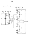
図1は、風力発電用設備に適用して好適な本発明の実施例1に係る電力変換装置を示す図であり、これらの設備は図3で後述するようにいずれも風力発電タワーに設置されている。 FIG. 1 is a diagram showing a power conversion apparatus according to a first embodiment of the present invention that is suitable for application to wind power generation facilities. These facilities are all installed in a wind power generation tower as will be described later with reference to FIG. ing.
風力発電用設備は、発電設備と電力変換設備に大別して把握することが可能であり、このうち発電設備は、同図の風車11、ギア10、発電機9、発電電力を直流に変換するパワーコンディショナ8などである。これに対し電力変換設備は、同図の残余の部分であり、いわゆるDC−DCコンバータを構成する回路部分である。本発明の実施例1に係る電力変換設備(DC−DCコンバータ)では、図1に示すようにこの部分を複数にモジュール分けして構成している。
Wind power generation equipment can be broadly classified into power generation equipment and power conversion equipment. Of these, the power generation equipment includes the
実施例1のDC−DCコンバータは、複数個(ここではNと表記)の単位モジュール1からなり、入力側を並列接続、出力側を直列接続して構成される。各単位モジュール1は、入力側のDC−AC変換手段2、出力側のAC−DC変換手段3、および両者を接続する多巻線変圧器4から構成されている。また複数のAC−DC変換手段3の出力側は直列接続されて、一方の直流出力端子はフィルタリアクトル5を介してブッシング22に接続される。複数のAC−DC変換手段3の出力側他方の直流出力端子はアースGNDに接続される。
The DC-DC converter according to the first embodiment includes a plurality of unit modules 1 (indicated here as N), and is configured by connecting the input side in parallel and connecting the output side in series. Each
本発明の実施例1においては、DC−DCコンバータを複数個(ここではNと表記)の単位モジュール1で形成するとともに、DC−DCコンバータの低圧部分と、高圧部分を別筐体に収納して、高圧部分の筐体内を油浸構造としている。図1で低圧部分筐体が50であり、高圧部分筐体が7である。低圧部分筐体2にはDC−AC変換手段2が収納され、高圧部分筐体7には、多巻線変圧器4、AC−DC変換手段3、フィルタリアクトル5、フィルタコンデンサ6などが収納される。
In the first embodiment of the present invention, the DC-DC converter is formed by a plurality of unit modules 1 (indicated here as N), and the low-voltage portion and the high-voltage portion of the DC-DC converter are housed in separate housings. In addition, the inside of the casing of the high pressure part has an oil immersion structure. In FIG. 1, the low-pressure partial housing is 50 and the high-pressure partial housing is 7. The low voltage
以下図1のDC−DCコンバータの各部機能について詳細に説明する。典型的な図1のDC−DCコンバータの設計においては、例えば7台の単位モジュール1(従ってN=7)とされ、DC−AC変換手段2とAC−DC変換手段3を接続する多巻線変圧器4の二次側数は5個(従ってk=5)である。kは単位モジュール1内のAC−DC変換手段3の個数に相当している。
Hereinafter, functions of each part of the DC-DC converter of FIG. 1 will be described in detail. In the typical DC-DC converter design of FIG. 1, for example, seven unit modules 1 (therefore, N = 7) are connected to connect the DC-AC conversion means 2 and the AC-DC conversion means 3. The number of secondary sides of the
DC−DCコンバータの主要機器である多巻線変圧器4の巻数比は1:nであり、入力側のDC−AC変換手段2の入力電圧Vin(一般には数kV)をn倍するとともに、入力側と出力側を電気的に絶縁する機能を持つ。なお、多巻線変圧器4に入力されるAC電圧は、DC−AC変換手段2により商用周波数以上の高周波(例えば1kHz)とするのがよい。
The turn ratio of the
なおDC−DCコンバータの設計にあたり、以下の点が考慮されている。出力側のAC−DC変換手段3を構成する電力用半導体素子の耐電圧には限界があるので、多巻線変圧器4の巻数比nを大きくすると、複数の電力用半導体素子を直列接続する必要が生じる。すると複数の電力用半導体素子間の特性がばらつくので、その影響を補償するスナバ回路等の手段を追加する必要があり、AC−DC変換手段3の損失が増加する。よって所望の変圧比を得るには単位モジュール1の段数Nを大きくとる構成が好適であるが、単位モジュール1の中で最も大きな体積を占める多巻線変圧器4の数が増えてしまう。そこで実施例1では、変圧器の出力側の巻線を複数個(ここではkと表記)に分割した多巻線変圧器4とし、それぞれの巻線をk個の出力側のAC−DC変換手段3に接続する。
In designing the DC-DC converter, the following points are taken into consideration. Since there is a limit to the withstand voltage of the power semiconductor elements constituting the AC-DC converting means 3 on the output side, when the turn ratio n of the
よって、DC−DCコンバータを構成する単位モジュール1は、1つの入力側のDC−AC変換手段2と、1つの多巻線変圧器4と、k個の出力側のAC−DC変換手段3を備える。k個の変換手段3の出力は、互いに直列接続される。
Therefore, the
この結果、DC−AC変換手段2およびAC−DC変換手段3で電圧が変化しない場合には、DC−DCコンバータの出力電圧Voutは、入力電圧Vinのn×k×N倍に昇圧されることになる。なお、AC−DC変換手段3より出力されるDC電圧には一般にリプルが残留するため、フィルタリアクトル5、およびフィルタコンデンサ6からなるフィルタ回路を通すことで、リプルが除去された直流電圧が得られる。
As a result, when the voltage does not change in the DC-
実施例1のDC−DCコンバータにおいて、最上段に位置するモジュール1内の出力側のAC−DC変換手段3、フィルタリアクトル5、およびフィルタコンデンサ6と接地GND間、および多巻線変圧器4の入力側と出力側の巻線間にはVout(おおむね80kV〜200kV程度)に相当する電位差が発生する。このため、各構成要素間の電気的接続を大気中で行うには、十分な絶縁距離を確保する必要があり、ブッシング等の部品点数が増え、装置の筐体体積も増えることになる。この筐体体積の問題は、風力発電用設備として狭隘な風力発電タワー内にDC−DCコンバータを設置するときに大きな障害となる。
In the DC-DC converter according to the first embodiment, the output-side AC-DC conversion means 3, the
そこで実施例1では、すべての単位モジュール1を構成する出力側のAC−DC変換手段3と多巻線変圧器4、およびフィルタリアクトル5とフィルタコンデンサ6を、単一の絶縁油タンク7に収納する。タンク7(高圧部分筐体)には複数個の低圧AC端子21と、1つの高圧直流(HVDC)を出力するブッシング22を備える。低圧AC端子21は、N個の入力側DC−AC変換手段2を収納した筐体2(低圧部分筐体)と接続される。DC−AC変換手段2には、接地電位と入力電圧Vin(一般に数kV)に相当する電位差しか発生しないので、筐体2内にN個のDC−AC変換手段2を収納し、相互の配線は大気中で接続すればよい。
Therefore, in the first embodiment, the output side AC-
図2は、本発明の実施例1に係る風力発電用DC−DCコンバータの絶縁油タンク7内の構造を示した透視斜視図(図2A)および正面断面図(図2B)である。ここでは一例として、単位モジュール1の数Nが7、出力側のAC−DC変換手段3の数kが5の場合を示しているが、それらの数を限定するものではない。また、実施例1では絶縁油タンク7の内部に隔壁71を設け、隔壁71の下部に鉄心41と巻線42から構成される多巻線変圧器4を4つ、上部に3つを備えた形態を示している。各多巻線変圧器4の手前側には、出力側AC−DC変換手段3が単位モジュール1台当り5個ずつ配設され、タンク7内には合計35個のAC−DC変換手段3が備えられる。隔壁71の上部にはフィルタリアクトル5とフィルタコンデンサ6を備える領域が設けられ、絶縁油タンク7の外部に設けた高圧DCブッシング22に接続される。また、タンク7の上部には単位モジュール1の数に相当する低圧AC端子21が設けられる。なおこれらの図において、7aは油面を示しており、以上説明した構成要素はすべて、絶縁油内に浸される。
FIG. 2 is a perspective view (FIG. 2A) and a front sectional view (FIG. 2B) showing the structure in the insulating
図3は、本発明が適用可能な風力発電タワー内の設備構成を示す縦断面図である。同図において、この左側は風力発電タワー12の全体の縦断面図を示しており、右側は風力発電タワー12の海水面近傍の拡大縦断面図を示している。
FIG. 3 is a longitudinal sectional view showing the equipment configuration in the wind power generation tower to which the present invention is applicable. In this figure, the left side shows a longitudinal sectional view of the entire wind
この図で、11は風車、11aはロータ、10はギア、9は発電機であり、ギア10、発電機9を収納したナセル11bが風力発電タワー12の上部に水平方向に回転可能な状態で備えられる。
In this figure, 11 is a windmill, 11a is a rotor, 10 is a gear, 9 is a generator, and a
風力発電タワー12の下部構造が右側に拡大表示されているように、風力発電タワー下部にはパワーコンディショナ8が設けられ、パワーコンディショナ8において風力発電タワー上部の発電機9からのAC出力電力が低圧(一般に数kV)のDC電力に変換される。さらにパワーコンディショナ8からのDC電力は、低圧DCケーブル13でDC−DCコンバータの入力側DC−AC変換手段を収納した筐体50(低圧部分筐体)に入力される。そして商用周波数以上の周波数を持つACに変換された低圧電力は、低圧ACケーブル14で絶縁油タンク7(高圧部分筐体)に入力される。低圧AC電力は、タンク7内に設けられた多巻線変圧器4と出力側AC−DC変換手段3により高圧DC(HVDC)電力に変換され、HVDCブッシング22を経由して、HVDCケーブル15により出力される。
As the lower structure of the wind
図3では、1つの風力発電タワー12における設備構成を示したが、実際の設備では複数の風力発電タワー12により直流集送電風力発電システムを構成することが多い。図4は、複数の風力発電タワー12からの出力を、直流集送電風力発電システムとして纏め、外部出力する場合の接続構成例を示している。
In FIG. 3, the equipment configuration in one wind
図4に示す直流集送電風力発電システム例では、洋上の複数の風力発電タワー12内の絶縁油タンク7(高圧部分筐体)から出力されるHVDC電力は、直流遮断器17を経由してHVDCケーブル15により並列に接続され、HVDC送電ケーブル15aに束ねられ、陸上へ長距離送電される。陸上に送電されたHVDC電力は、HVDC−商用AC変換手段18により高圧商用AC出力19に変換され、電力系統に接続される。
In the example of the direct current collection and transmission wind power generation system shown in FIG. 4, the HVDC power output from the insulating oil tanks 7 (high-pressure partial housings) in the plurality of offshore wind power generation towers 12 is connected to the HVDC via the direct
次に、本発明のDC−DCコンバータを構成する入力側のDC−AC変換手段2、および出力側AC−DC変換手段3の回路方式の例を、図7から図11を用いて説明する。これらの例は実施例1を含め、後述するすべての実施例に適用可能である。 Next, an example of the circuit system of the input side DC-AC conversion means 2 and the output side AC-DC conversion means 3 constituting the DC-DC converter of the present invention will be described with reference to FIGS. These examples are applicable to all the embodiments described later including the first embodiment.
図7は、入力側DC−AC変換手段2を2レベル型フルブリッジインバータ回路で、出力側AC−DC変換手段3を整流回路で構成した例である。入力側DC−AC変換手段2は、4組のIGBT等のスイッチング素子23と負荷転流ダイオード24と、1つの入力コンデンサ26がフルブリッジ回路を構成する。多巻線変圧器4には、振幅がVinで、商用周波数以上の周波数を持つAC電圧が入力される。該AC電圧は、IGBT等のスイッチング素子23のゲート端子に入力される信号を制御することにより、任意のデューティ比を持つ矩形波や、パルス幅変調波(PWM波)等の時間波形を持つ。多巻線変圧器4のk分割された出力側巻線より出力されるAC電圧は、4つの整流ダイオード31と、1つの出力コンデンサ32からなるk組の整流回路が直列接続された、出力側AC−DC変換手段3に入力され、Vinのn×k倍に昇圧されたDC電圧に変換される。
FIG. 7 shows an example in which the input side DC-AC conversion means 2 is constituted by a two-level full-bridge inverter circuit, and the output side AC-DC conversion means 3 is constituted by a rectifier circuit. In the input side DC-
図8は、入力側DC−AC変換手段2を3レベル型ハーフブリッジインバータ回路で、出力側AC−DC変換手段3を整流回路で構成した例である。入力側DC−AC変換手段2は、4組のIGBT等のスイッチング素子23と負荷転流ダイオード24、2つのクランプダイオード25、および2つの入力コンデンサ26がハーフブリッジ回路を構成する。多巻線変圧器4には、振幅がVinの1/2で、商用周波数以上の周波数を持つAC電圧が入力される。該AC電圧は、IGBT等のスイッチング素子23のゲート端子に入力される信号を制御することにより、任意のデューティ比を持つ矩形波や、パルス幅変調波(PWM波)等の時間波形を持つ。多巻線変圧器4のk分割された出力側巻線より出力されるAC電圧は、4つの整流ダイオード31と、1つの出力コンデンサ32からなるk組の整流回路が直列接続された、出力側AC−DC変換手段3に入力され、Vinのn×k/2倍に昇圧されたDC電圧に変換される。
FIG. 8 shows an example in which the input side DC-AC conversion means 2 is constituted by a three-level half-bridge inverter circuit and the output side AC-DC conversion means 3 is constituted by a rectifier circuit. In the input side DC-AC conversion means 2, four sets of switching
図9は、入力側DC−AC変換手段2を3レベル型フルブリッジインバータ回路で、出力側AC−DC変換手段3を整流回路で構成した例である。入力側DC−AC変換手段2は、8組のIGBT等のスイッチング素子23と負荷転流ダイオード24、4つのクランプダイオード25、および2つの入力コンデンサ26が3レベルフルブリッジ回路を構成する。多巻線変圧器4には、振幅がVinで、商用周波数以上の周波数を持つAC電圧が入力される。該AC電圧は、IGBT等のスイッチング素子23のゲート端子に入力される信号を制御することにより、任意のデューティ比を持つ矩形波や、パルス幅変調波(PWM波)等の時間波形を持つ。多巻線変圧器4のk分割された出力側巻線より出力されるAC電圧は、4つの整流ダイオード31と、1つの出力コンデンサ32からなるk組の整流回路が直列接続された、出力側AC−DC変換手段3に入力され、Vinのn×k倍に昇圧されたDC電圧に変換される。
FIG. 9 shows an example in which the input side DC-AC conversion means 2 is constituted by a three-level full-bridge inverter circuit and the output side AC-DC conversion means 3 is constituted by a rectifier circuit. In the input side DC-
図10は、入力側DC−AC変換手段2と、出力側AC−DC変換手段3が、ともに2レベル型フルブリッジインバータ回路、およびコンバータ回路で構成した例であり、それぞれ4組のIGBT等のスイッチング素子23と負荷転流ダイオード24と、1つの入力コンデンサ26、または1つの出力コンデンサ32がフルブリッジ回路を構成する。多巻線変圧器4には、振幅がVinで、商用周波数以上の周波数を持つAC電圧が入力される。該AC電圧は、入力側変換手段2のIGBT等のスイッチング素子23のゲート端子に入力される信号を制御することにより、任意のデューティ比を持つ矩形波や、パルス幅変調波(PWM波)等の時間波形を持つ。多巻線変圧器4のk分割された出力側巻線より出力されるAC電圧は、k組のフルブリッジ型コンバータ回路が直列接続された、出力側AC−DC変換手段3に入力され、Vinのn×k倍に昇圧されたDC電圧に変換される。出力側AC−DC変換手段3を構成するIGBT等のスイッチング素子23のゲート端子に入力される信号を制御することにより、k組の回路間の位相を調整し、よりリプルの少ないDC電圧に変換することも可能になる。
FIG. 10 shows an example in which the input side DC-AC conversion means 2 and the output side AC-DC conversion means 3 are both constituted by a two-level full-bridge inverter circuit and a converter circuit. The switching
図11は、入力側DC−AC変換手段2と、出力側AC−DC変換手段3が、ともに3レベル型ハーフブリッジインバータ回路、およびコンバータ回路で構成した例であり、それぞれ4組のIGBT等のスイッチング素子23と負荷転流ダイオード24、2つのクランプダイオード25、2つの入力コンデンサ26、または2つの出力コンデンサ32がハーフブリッジ回路を構成する。多巻線変圧器4には、振幅がVinの1/2で、商用周波数以上の周波数を持つAC電圧が入力される。該AC電圧は、入力側変換手段2のIGBT等のスイッチング素子23のゲート端子に入力される信号を制御することにより、任意のデューティ比を持つ矩形波や、パルス幅変調波(PWM波)等の時間波形を持つ。多巻線変圧器4のk分割された出力側巻線より出力されるAC電圧は、k組のハーフブリッジ型コンバータ回路が直列接続された、出力側AC−DC変換手段3に入力され、Vinのn×k倍に昇圧されたDC電圧に変換される。出力側AC−DC変換手段3を構成するIGBT等のスイッチング素子23のゲート端子に入力される信号を制御することにより、k組の回路間の位相を調整し、よりリプルの少ないDC電圧に変換することも可能になる。
FIG. 11 shows an example in which the input side DC-AC conversion means 2 and the output side AC-DC conversion means 3 are both constituted by a three-level half-bridge inverter circuit and a converter circuit. The switching
以上、図7から図11に示した回路の組み合わせはこれらに限定するものではない。図に示した回路の異なる組み合わせ、または本発明で示していないインバータ、コンバータ、整流回路の任意の組み合わせによっても、本発明が提供する効果は同様に得られる。 As described above, the combinations of the circuits shown in FIGS. 7 to 11 are not limited to these. The effects provided by the present invention can be similarly obtained by different combinations of the circuits shown in the drawings or any combination of inverters, converters, and rectifier circuits that are not shown in the present invention.
次に、本発明のDC−DCコンバータを構成する多巻線変圧器4の例を、図12から図16を用いて説明する。ここで説明する例は本実施例を含め、後述するすべての実施例に適用可能である。
Next, an example of the
図12は、本発明のDC−DCコンバータ内の多巻線変圧器4の構造を示す縦断面図(図12A)および上面図(図12B)である。多巻線変圧器4は、単相鉄心41と、2箇所の磁脚に2つに分けて巻回された巻線42から構成される。鉄心41は、一端が開放された薄帯状の磁性材料を複数枚積層し、巻線42を挿入した後に開放部を閉じた、ラップ接合部41aを持つ巻鉄心により構成される。薄帯状磁性材料は、商用周波数以上の高周波における磁気損失(鉄損)が小さい、鉄を主成分とするアモルファス合金等を用いるのが好適である。
FIG. 12 is a longitudinal sectional view (FIG. 12A) and a top view (FIG. 12B) showing the structure of the
鉄心41の磁脚部に巻回された巻線42は、板状の巻線材料から構成される。入力側(1次)巻線42aと、図の縦方向にk分割された、n組の出力側(2次)巻線42bが、交互に巻回される。nは入力側巻線に対する出力側巻線の巻数比であり、本図ではわかりやすくするため、n=2の場合を示している。入力側巻線の巻数をTとすると、1箇所の磁脚には上記の構造を持つ巻線群がT/2回巻回される。このように、多巻線変圧器4の入力側巻線42aと出力側巻線42bを交互に巻回することにより、巻線間の近接効果が低減され、変圧器の損失が低減し、DC−DCコンバータの変換効率が向上する。
The winding 42 wound around the magnetic leg portion of the
図13は、本発明のDC−DCコンバータ内の多巻線変圧器における、1本の磁脚に巻回された巻線の展開図、図14は、該巻線の結線図である。本図ではわかりやすくするため、k=3、n=2の場合を示している。板状の入力側巻線42aと出力側巻線42bは、巻き始めと巻き終わりの終端部に、巻線構造の上側、または下側に飛び出す形状の電極部が設けられる。図13に示した各電極に付した記号は、図14に示した各記号に対応する。同図に示した第2脚の結線は、第1脚と対称になるように施され、第1脚と第2脚に巻回した巻線の各電極は、適切な断面積を持つ導体材料により接続される。 FIG. 13 is a development view of the winding wound around one magnetic leg in the multi-winding transformer in the DC-DC converter of the present invention, and FIG. 14 is a connection diagram of the winding. In this figure, for the sake of easy understanding, the case of k = 3 and n = 2 is shown. The plate-like input-side winding 42a and output-side winding 42b are provided with electrode portions that protrude to the upper side or the lower side of the winding structure at the beginning and end of winding. Symbols attached to the electrodes shown in FIG. 13 correspond to the symbols shown in FIG. The connection of the second leg shown in the figure is made symmetrical to the first leg, and each electrode of the winding wound around the first leg and the second leg is a conductor material having an appropriate cross-sectional area. Connected by.
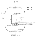
図15は、本発明のDC−DCコンバータ内の多巻線変圧器の鉄心41に巻回した巻線42の上面図であり、巻線電極の配置、および相互の接続を示している。実線で示した電極は巻線の上側に、破線で示した電極は巻線の下側に飛び出していることを示す。入力側巻線の電極P−1、およびP−2と、出力側巻線の電極群S−1、およびS−2は、互いに鉄心41をはさんだ反対側に設けられ、十分な絶縁距離が確保される。また、出力側巻線のn=1に相当する巻線の巻き終わりの電極群S11b、S12b、S13bと、n=2に相当する巻線の巻き始めの電極群S21a、S22a、S23aは、巻線の下側で、適切な断面積を持つ導体材料により接続される。
FIG. 15 is a top view of the winding 42 wound around the
図16は、図15中に示したA部における巻線構造の拡大上面図(図16A)、および巻線の断面図(図16B)である。鉄心41の直近には入力側巻線42aが配置され、その外側に、巻数比n(ここではn=2)に等しい枚数の出力側巻線42bと、入力側巻線42aが交互に巻回される。巻線42aと42bの間には、最大でDC−DCコンバータの出力電圧Vout(一般におおむね80kV〜200kV)と入力電圧Vin(一般に数kV)の差に相当する電位差が発生するため、両者を適切な絶縁距離に保つための絶縁材43が設けられる。絶縁材は断面が略矩形の棒状材とし、一定の間隔を保ちつつ巻線42aと42bの間に配設し、相互の間隙を絶縁油が循環する構造とするのが好適である。
16 is an enlarged top view (FIG. 16A) of the winding structure in the A portion shown in FIG. 15 and a cross-sectional view of the winding (FIG. 16B). An input side winding 42a is arranged in the immediate vicinity of the
また、図16Bに示したように、巻線42a、および42bは、適切な厚さの絶縁紙44で被覆を施した上で、磁脚に巻回するのが好適である。該絶縁紙が持つ耐電圧特性と、絶縁材43により確保される絶縁油中での空間距離の組み合わせにより、巻線42aと巻線42b間の絶縁耐電圧が得られる。
Further, as shown in FIG. 16B, the
本発明では、風力発電用設備に適用して好適な電力変換装置(DC−DCコンバータ)を得ることを目的としており、そのために第1段階の対策として複数個(ここではNと表記)の単位モジュール1で構成し、DC−AC変換手段2とAC−DC変換手段3間を多巻線変圧器4で接続した。これにより、図20に示した従来構成に比較して、体積を20%程度に低減が可能である。さらに第2段階の対策としてDC−DCコンバータの高圧部分を筐体内に油浸としたことで、最終的に体積を10%程度まで低減することができた。
The object of the present invention is to obtain a suitable power conversion device (DC-DC converter) that can be applied to wind power generation facilities. For this purpose, a plurality of units (indicated here as N) are used as a first-stage countermeasure. A
図4に直流集送電風力発電システムの事例を挙げて説明したが、この直流集送電風力発電システムは図5のように構成されてもよい。 Although the example of the DC power collection / transmission wind power generation system has been described with reference to FIG. 4, the DC power collection / transmission wind power generation system may be configured as illustrated in FIG. 5.
図5は、本発明の実施例2に係る直流集送電風力発電システムの系統図である。複数の風力発電タワー12の内部には図3に示した、実施例1と同一の機器要素が備えられ、HVDCケーブル15を経由してHVDC電力が出力される。各風力発電タワー12からのHVDC電力は、洋上に設けられた洋上プラットフォーム16に集められ、洋上プラットフォーム上に配設された直流遮断器17を経由して並列に接続され、HVDC送電ケーブル15aに束ねられ、陸上へ長距離送電される。陸上に送電されたHVDC電力は、HVDC−商用AC変換手段18により高圧商用AC出力19に変換され、電力系統に接続される。
FIG. 5 is a system diagram of a DC power collection / transmission wind power generation system according to
図6は、本発明の実施例3に係る直流集送電風力発電システムの系統図である。実施例3では、複数の風力発電タワー12より出力されるDC電力は中電圧(MVDC、一般におおむね10kV〜60kV程度)である。個々の風力発電タワー12内には、図3に示した構成によるDC−DCコンバータが備えられ、昇圧比を実施例1、および実施例2より小さくすることで、MVDC電力を出力する構成としてもよい。MVDC電力は、MVDCケーブル15bを経由して、洋上プラットフォーム16に集められる。そして直流遮断器17を経由し、筐体50内に備えられた個々の入力側DC−AC変換手段2に入力される。筐体50から出力されるAC電力は、複数の変圧器、複数の出力側AC−DC変換手段、およびフィルタ素子を収納した絶縁油タンク7に入力されてHVDC電力に変換され、HVDC送電ケーブル15aにより陸上へ長距離送電される。陸上に送電されたHVDC電力は、HVDC−商用AC変換手段18により高圧商用AC出力19に変換され、電力系統に接続される。
FIG. 6 is a system diagram of a DC power collection / transmission wind power generation system according to
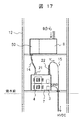
図17は、本発明の実施例4に係る風力発電タワー12の海水面近傍の構造を示す縦断面図である。風力発電タワー12に備えられた発電機9からのAC出力電力は、パワーコンディショナ8により低圧(一般に数kV)DC電力に変換される。パワーコンディショナ8からのDC電力は、DC−DCコンバータの入力側DC−AC変換手段を収納した筐体50に入力されるが、実施例4ではパワーコンディショナ8と一体型の筐体50とする。
FIG. 17: is a longitudinal cross-sectional view which shows the structure of the seawater surface vicinity of the wind
そして商用周波数以上の周波数を持つACに変換された低圧電力は、低圧ACケーブル14で絶縁油タンク7に入力される。低圧AC電力は、絶縁油タンク7内に設けられた多巻線変圧器4と出力側AC−DC変換手段3により高圧DC(HVDC)電力に変換され、HVDCブッシング22を経由して、HVDCケーブル15により出力される。本実施例に示すような構成とすることで、風力発電タワー12内の低圧系統と高圧系統は独立した筐体内に収納されるため、両筐体を異なるフロアに配置することにより、タワー内の空間をより効果的に使うことができ、機器のメンテナンス上の安全性も高まる。
The low-voltage power converted into AC having a frequency equal to or higher than the commercial frequency is input to the insulating
図18は、本発明の実施例5に係る風力発電用DC−DCコンバータの回路ブロック図である。図1に示した、実施例1における回路ブロック図と共通する記号、および機能の詳細な説明は省略する。実施例5では、パワーコンディショナ8から出力される低圧DC電圧は+Vinと−Vinであり、それぞれの電圧が複数の入力側DC−AC変換手段2を収納した筐体50に入力される。そして実施例1と同一の構成のDC−DCコンバータ1により、高圧DC(HVDC)電圧+Vout、および−Voutに変換される。DC−DC−コンバータを構成する複数の多巻線変圧器4と複数の出力側AC−DC変換手段3、およびフィルタリアクトル5とフィルタコンデンサ6は単一の絶縁油タンク7に収納される。絶縁油タンクには複数個の低圧AC端子21と、+Voutと−VoutのHVDC電力を出力するための2つのブッシング22、および22bを備える。
FIG. 18 is a circuit block diagram of a DC-DC converter for wind power generation according to
図19は、本発明の実施例6に係る風力発電用DC−DCコンバータの回路ブロック図である。図1に示した実施例1における回路ブロック図と共通する記号、および機能の詳細な説明は省略する。本実施例では、DC−DCコンバータを構成するすべての多巻線変圧器4と、上段に位置する任意の数の出力側AC−DC変換手段3、およびフィルタリアクトル5とフィルタコンデンサ6を単一の絶縁油タンク7に収納する。下段に位置する出力側AC−DC変換手段3と接地間に発生する電位はHVDCに比べて十分低いため、絶縁油タンク7内に収納せず、大気中に備えても問題なく機能する。DC−DCコンバータを構成する一部の出力側AC−DC変換手段3を大気中に備えることで、絶縁油タンク内に収納した該変換手段が故障する確率が減り、交換の手間を減ずることができる。
FIG. 19 is a circuit block diagram of a DC-DC converter for wind power generation according to
以上、本願で例示した各実施例は、単独で用いてもよいし、複数の実施例を組み合わせて適用しても、本発明が示す効果は同様に得られる。 As mentioned above, each Example illustrated by this application may be used independently, and even if it combines and applies a several Example, the effect which this invention shows is acquired similarly.
1:DC−DCコンバータの単位モジュール
2:DC−AC変換手段
3:AC−DC変換手段
4:多巻線変圧器
41:鉄心
41a:ラップ接合部
42:巻線
42a:入力側(1次)巻線
42b:出力側(2次)巻線
43:絶縁物
44:絶縁紙
5:フィルタリアクトル
6:フィルタコンデンサ
7:絶縁油タンク
71:絶縁油タンク内の隔壁
7a:絶縁油タンク内の油面
8:パワーコンディショナ
9:発電機
10:ギア
11:風車
11a:ロータ
11b:ナセル
12:風力発電タワー
13:低圧DCケーブル
14:低圧ACケーブル
15:高圧DC(HVDC)ケーブル
15a:HVDC送電ケーブル
15b:中圧DC(MVDC)ケーブル
16:洋上プラットフォーム
17:直流遮断器
18:HVDC−高圧商用AC変換手段
19:高圧商用AC出力
21:低圧AC端子
22:高圧DC(HVDC)ブッシング
22b:負極HVDCブッシング
23:スイッチング素子
24:負荷転流ダイオード
25:クランプダイオード
26:入力コンデンサ
31:整流ダイオード
32:出力コンデンサ
50:複数のDC−AC変換手段を納めた筐体
N:DC−DCコンバータのモジュール数
n:多巻線変圧器の入力側巻線に対する出力側巻線の巻数比
k:多巻線変圧器の出力側巻線の分割数
T:多巻線変圧器の入力側巻線の巻数
1: DC-DC converter unit module 2: DC-AC conversion means 3: AC-DC conversion means 4: multi-winding transformer 41: iron core 41a: lap joint 42: winding 42a: input side (primary) Winding 42b: Output side (secondary) winding 43: Insulator 44: Insulating paper 5: Filter reactor 6: Filter capacitor 7: Insulating oil tank 71: Partition wall 7a in the insulating oil tank 7: Oil surface in the insulating oil tank 8: Power conditioner 9: Generator 10: Gear 11: Windmill 11a: Rotor 11b: Nacelle 12: Wind power generation tower 13: Low voltage DC cable 14: Low voltage AC cable 15: High voltage DC (HVDC) cable 15a: HVDC power transmission cable 15b : Medium voltage DC (MVDC) cable 16: Offshore platform 17: DC circuit breaker 18: HVDC-high voltage commercial AC conversion means 19: High voltage commercial A Output 21: Low voltage AC terminal 22: High voltage DC (HVDC) bushing 22b: Negative HVDC bushing 23: Switching element 24: Load commutation diode 25: Clamp diode 26: Input capacitor 31: Rectifier diode 32: Output capacitor 50: Multiple DC -Housing containing AC conversion means N: Number of modules of DC-DC converter n: Turn ratio of output side winding to input side winding of multi-winding transformer k: Output side winding of multi-winding transformer Division number T: Number of turns of input winding of multi-winding transformer
Claims (15)
前記DC−AC変換手段と前記変圧器と前記AC−DC変換手段を備えた単位モジュールを複数組備え、複数組の単位モジュールの前記DC−AC変換手段の入力側を並列接続して前記AC−DC変換手段の出力側を直列接続し、
前記各単位モジュール内の前記変圧器を多巻線変圧器として、その二次側巻線ごとに前記AC−DC変換手段を備え、
前記複数組の単位モジュール内の少なくとも前記変圧器と前記AC−DC変換手段を共通の油浸筐体内に収納することを特徴とする電力変換装置。 DC-AC converting means for converting direct current to alternating current, a transformer for receiving the alternating current output of the DC-AC converting means, and an AC-DC converting means for converting the alternating current output of the transformer to direct current A device,
A plurality of unit modules each including the DC-AC conversion unit, the transformer, and the AC-DC conversion unit are provided, and the input side of the DC-AC conversion unit of the plurality of unit modules is connected in parallel to form the AC- The output side of the DC conversion means is connected in series ,
The transformer in each unit module is a multi-winding transformer, and the AC-DC conversion means is provided for each secondary winding of the transformer.
A power conversion device characterized in that at least the transformer and the AC-DC conversion means in the plurality of sets of unit modules are housed in a common oil immersion housing.
前記DC−AC変換手段を収納する第1の筐体と、前記多巻線変圧器及び前記AC−DC変換手段を収納する第2の筐体を備え、前記第2の筐体を共通の油浸筐体として第2の筐体内が油浸されていることを特徴とする電力変換装置。 The power conversion device according to claim 1,
A first housing that houses the DC-AC conversion means; a second housing that houses the multi-winding transformer and the AC-DC conversion means ; power conversion apparatus characterized by the second housing is immersed oil as Hitakatamitai.
前記複数のモジュール内の前記変圧器と前記AC−DC変換手段、および前記モジュールの出力側に接続されたフィルタ用素子を単一の絶縁油タンク内に収納し、各モジュール内、モジュール間、およびモジュールとフィルタ用素子間の配線を前記絶縁油タンク内で接続し、絶縁油タンク外に入力用の交流用端子と出力用の直流ブッシングを備えることを特徴とする電力変換装置。 A plurality of DC boosting / insulating modules comprising an input side DC-AC converting means , an output side AC-DC converting means , and a transformer, the input side being connected in parallel and the output side being connected in series, the DC boosting A power conversion device having a function,
The transformer in the plurality of modules, the AC-DC conversion means, and the filter element connected to the output side of the module are housed in a single insulating oil tank, in each module, between the modules, and A power converter comprising: a wiring between a module and a filter element connected in the insulating oil tank; and an AC terminal for input and a DC bushing for output provided outside the insulating oil tank.
前記複数のモジュールのうち、接地電位に近いモジュール内のAC−DC変換手段を前記絶縁油タンクの外側に設置したことを特徴とする電力変換装置。 The power conversion device according to claim 3 ,
Among the plurality of modules, an AC-DC conversion means in a module close to a ground potential is installed outside the insulating oil tank.
前記各モジュール内の前記変圧器の出力側巻線を複数に分割し、個々の出力側巻線を複数の前記AC−DC変換手段の入力側端子に接続し、すべての前記AC−DC変換手段の出力側端子を直列接続したことを特徴とする電力変換装置。 The power conversion device according to claim 3 or 4 , wherein
The output side windings of the transformer in each module are divided into a plurality of parts, and the individual output side windings are connected to the input side terminals of the plurality of AC-DC conversion units, and all the AC-DC conversion units are connected. A power converter characterized by connecting the output side terminals in series.
前記各モジュール内の前記変圧器の入力側巻線と出力側巻線は、適切な絶縁距離を保ちつつ交互に巻回したこと、を特徴とする電力変換装置。 The power conversion device according to any one of claims 3 to 5 ,
The power converter according to claim 1, wherein the input side winding and the output side winding of the transformer in each module are alternately wound while maintaining an appropriate insulation distance.
前記各モジュール内の前記変圧器の入力側巻線および出力側巻線は断面が略矩形の導体材料により構成され、絶縁性材料により被覆されていることを特徴とする電力変換装置。 The power conversion device according to any one of claims 3 to 6 ,
The power converter according to claim 1, wherein an input-side winding and an output-side winding of the transformer in each module are made of a conductor material having a substantially rectangular cross section and are covered with an insulating material .
前記各モジュール内の前記変圧器の入力側巻線と出力側巻線の終端部には、巻線構造の上側、または下側に飛び出す形状の電極が設けられ、該電極間を、適切な断面積を持つ導体材料により接続したことを特徴とする電力変換装置。 The power conversion device according to any one of claims 3 to 7 ,
An electrode having a shape protruding to the upper side or the lower side of the winding structure is provided at the terminal end of the input side winding and the output side winding of the transformer in each module, and an appropriate gap is provided between the electrodes. A power converter characterized by being connected by a conductive material having an area.
前記各モジュール内の前記変圧器は、商用周波数以上の高周波で励磁し、前記変圧器の鉄心は、薄帯状の磁性材料を複数枚巻回して構成される巻鉄心であることを特徴とする電力変換装置。 The power conversion device according to any one of claims 3 to 8 ,
The transformer in each module is excited at a high frequency higher than a commercial frequency, and the iron core of the transformer is a wound iron core formed by winding a plurality of thin strip-shaped magnetic materials. Conversion device.
前記各モジュール内の前記変圧器の鉄心は、鉄を主成分とするアモルファス構造、または微細結晶構造を有する薄帯状合金により構成されていることを特徴とする電力変換装置。 The power conversion device according to any one of claims 3 to 9 ,
The power conversion device according to claim 1, wherein an iron core of the transformer in each module is made of an amorphous structure having iron as a main component or a thin-band alloy having a fine crystal structure.
前記モジュール内の入力側の前記DC−AC変換手段は、スイッチング素子とダイオードからなる2レベルフルブリッジ型インバータ回路、または3レベルハーフブリッジ型インバータ回路、または3レベルフルブリッジ型インバータ回路、のいずれかで構成されていることを特徴とする電力変換装置。 The power conversion device according to any one of claims 3 to 10 , wherein
The DC-AC conversion means on the input side in the module is either a two-level full bridge inverter circuit comprising a switching element and a diode, a three level half bridge inverter circuit, or a three level full bridge inverter circuit. It is comprised by the power converter device characterized by the above-mentioned.
前記モジュール内の出力側のAC−DC変換手段は、スイッチング素子とダイオードからなる2レベルフルブリッジ型コンバータ回路、または3レベルハーフブリッジ型コンバータ回路、または3レベルフルブリッジ型コンバータ回路、またはダイオードからなる整流回路、のいずれかで構成されていることを特徴とする電力変換装置。 The power conversion device according to any one of claims 3 to 11 ,
The output-side AC-DC converting means in the module comprises a two-level full-bridge converter circuit comprising a switching element and a diode, a three-level half-bridge converter circuit, a three-level full-bridge converter circuit, or a diode. A power conversion device comprising any of the rectifier circuits.
前記モジュールの入力側のDC−AC変換手段を納めた筐体と、前記単一の絶縁油タンクを、洋上に設置した風力発電タワー内に収納し、該風力発電タワーからの発電電力を直流電力に変換して出力することを特徴とする風力発電システム。 A wind power generation system comprising the power conversion device according to any one of claims 3 to 12 ,
The casing containing the DC-AC conversion means on the input side of the module and the single insulating oil tank are housed in a wind power generation tower installed on the ocean, and the generated power from the wind power generation tower is converted to DC power. A wind power generation system characterized by being converted into an output.
洋上に設置した複数の風力発電タワーから出力される直流電力を複数の直流遮断器を経由した後に並列接続して一箇所に集め、該直流電力を陸上へ送電することを特徴とする風力発電システム。 A wind power generation system comprising the power conversion device according to any one of claims 3 to 12 ,
A wind power generation system characterized in that direct current power output from a plurality of wind power generation towers installed on the ocean passes through a plurality of direct current circuit breakers and is connected in parallel to be collected in one place, and the direct current power is transmitted to land .
洋上に設置した複数の風力発電タワーから出力される直流電力を複数の直流遮断器を経由した後に洋上に設置したプラットフォームに集め、該プラットフォーム上に備えた第2の電力変換装置により1系統の直流電力に変換し陸上へ送電することを特徴とする風力発電システム。 A wind power generation system comprising the power conversion device according to any one of claims 3 to 12 ,
DC power output from a plurality of wind power generation towers installed on the ocean is collected on a platform installed on the ocean after passing through a plurality of DC circuit breakers, and one system of DC power is collected by a second power conversion device provided on the platform. A wind power generation system that converts electricity into electricity and transmits it to land.
Priority Applications (2)
| Application Number | Priority Date | Filing Date | Title |
|---|---|---|---|
| JP2015128220A JP6470645B2 (en) | 2015-06-26 | 2015-06-26 | Power converter and wind power generation system |
| EP16171241.9A EP3109992B1 (en) | 2015-06-26 | 2016-05-25 | Power conversion apparatus and wind turbine generation system |
Applications Claiming Priority (1)
| Application Number | Priority Date | Filing Date | Title |
|---|---|---|---|
| JP2015128220A JP6470645B2 (en) | 2015-06-26 | 2015-06-26 | Power converter and wind power generation system |
Publications (2)
| Publication Number | Publication Date |
|---|---|
| JP2017011964A JP2017011964A (en) | 2017-01-12 |
| JP6470645B2 true JP6470645B2 (en) | 2019-02-13 |
Family
ID=56080333
Family Applications (1)
| Application Number | Title | Priority Date | Filing Date |
|---|---|---|---|
| JP2015128220A Active JP6470645B2 (en) | 2015-06-26 | 2015-06-26 | Power converter and wind power generation system |
Country Status (2)
| Country | Link |
|---|---|
| EP (1) | EP3109992B1 (en) |
| JP (1) | JP6470645B2 (en) |
Families Citing this family (27)
| Publication number | Priority date | Publication date | Assignee | Title |
|---|---|---|---|---|
| US20180187652A1 (en) * | 2017-01-05 | 2018-07-05 | General Electric Company | Power Converter for Full Conversion Wind Turbine Systems |
| JP2018119542A (en) | 2017-01-26 | 2018-08-02 | 株式会社デンソー | Ejector |
| DE102017106436A1 (en) * | 2017-03-24 | 2018-09-27 | Wobben Properties Gmbh | Wind farm with several wind turbines |
| CN108199594A (en) * | 2017-05-31 | 2018-06-22 | 北京金风科创风电设备有限公司 | High-voltage direct-current generator, wind generating set and wind farm |
| JP7079571B2 (en) * | 2017-06-09 | 2022-06-02 | 株式会社タムラ製作所 | Reactor device |
| CN107508311B (en) * | 2017-07-06 | 2019-05-24 | 上海交通大学 | The method and system of the promotion operational efficiency of parallel connection type wind electric converter |
| JP6932373B2 (en) * | 2017-08-22 | 2021-09-08 | 株式会社アイケイエス | Control device for 3-terminal static DC transformer |
| WO2019073650A1 (en) * | 2017-10-12 | 2019-04-18 | 三菱電機株式会社 | Transformer and power conversion device |
| EP3696961A4 (en) | 2017-10-12 | 2020-12-09 | Mitsubishi Electric Corporation | Power conversion device |
| JP6955988B2 (en) * | 2017-12-11 | 2021-10-27 | 株式会社日立製作所 | Power converter unit and power converter |
| CN107947222A (en) * | 2017-12-26 | 2018-04-20 | 北京金风科创风电设备有限公司 | Direct current fan power transmission system |
| CN108111035A (en) * | 2018-01-31 | 2018-06-01 | 阳光电源股份有限公司 | A kind of photovoltaic solid-state transformer, photovoltaic inverting system and bidirectional high-pressure current transformer |
| JP7205072B2 (en) * | 2018-04-04 | 2023-01-17 | 株式会社豊田中央研究所 | power converter |
| JP7087941B2 (en) * | 2018-11-16 | 2022-06-21 | 株式会社村田製作所 | Energy harvesting equipment |
| US10971934B2 (en) | 2018-12-31 | 2021-04-06 | Abb Schweiz Ag | Distribution networks with flexible direct current interconnection system |
| US11121543B2 (en) | 2018-12-31 | 2021-09-14 | Abb Schweiz Ag | Fault mitigation in medium voltage distribution networks |
| US10819112B1 (en) | 2019-03-27 | 2020-10-27 | Abb Schweiz Ag | Feeder line fault response using direct current interconnection system |
| US11031773B2 (en) | 2019-03-27 | 2021-06-08 | Abb Power Grids Switzerland Ag | Transformer isolation response using direct current link |
| CN110247560A (en) * | 2019-07-10 | 2019-09-17 | 南方电网科学研究院有限责任公司 | Flexible direct current converter station valve hall and converter valve inlet wire system |
| CN110492721B (en) * | 2019-08-23 | 2022-06-17 | 西安西电电力系统有限公司 | Multiport power electronic transformer |
| JP6833131B1 (en) * | 2020-04-20 | 2021-02-24 | 三菱電機株式会社 | Power converter |
| CA3186203A1 (en) * | 2020-07-15 | 2022-01-20 | Mahdi S. ATTEIA | Dc to dc boost converter |
| CN112086964A (en) * | 2020-09-07 | 2020-12-15 | 易事特集团(河南)有限公司 | AC power supply system |
| CN114362335A (en) * | 2020-10-13 | 2022-04-15 | 台达电子工业股份有限公司 | Power conversion framework applied to solid-state transformer and corresponding charging system |
| JP7183238B2 (en) * | 2020-10-26 | 2022-12-05 | 三菱電機株式会社 | power converter |
| KR102515718B1 (en) * | 2020-11-02 | 2023-03-29 | 명지대학교 산학협력단 | Battery charger with very side charge voltage range |
| CN114188933B (en) * | 2021-12-09 | 2023-06-02 | 南方电网电力科技股份有限公司 | Direct current collecting system of wave energy power generation device and control method and system thereof |
Family Cites Families (19)
| Publication number | Priority date | Publication date | Assignee | Title |
|---|---|---|---|---|
| JP2569432Y2 (en) * | 1991-03-28 | 1998-04-22 | 田淵電機株式会社 | Planar type coil device |
| DE19723068C1 (en) * | 1997-06-02 | 1999-05-12 | Vacuumschmelze Gmbh | Inductive component |
| US6738275B1 (en) * | 1999-11-10 | 2004-05-18 | Electromed Internationale Ltee. | High-voltage x-ray generator |
| JP2002199711A (en) * | 2000-12-25 | 2002-07-12 | Fujitsu Denso Ltd | Failure detector for dc-dc converter |
| JP4457817B2 (en) * | 2004-09-10 | 2010-04-28 | オムロン株式会社 | Power conditioner DC / DC converter |
| US7233079B1 (en) * | 2005-10-18 | 2007-06-19 | Willard Cooper | Renewable energy electric power generating system |
| JP4969927B2 (en) * | 2006-06-29 | 2012-07-04 | ニチコン株式会社 | DC high voltage generator |
| JP5335185B2 (en) * | 2006-10-16 | 2013-11-06 | 株式会社日立メディコ | High voltage generator |
| US8058962B2 (en) * | 2008-09-18 | 2011-11-15 | Silitek Electronic (Guangzhou) Co., Ltd. | Center-tapped transformer |
| KR101030632B1 (en) * | 2009-03-18 | 2011-04-20 | 서울대학교산학협력단 | power converter and power conversion system using high frequency transformer |
| US20120175962A1 (en) * | 2011-01-11 | 2012-07-12 | Converteam Technology Ltd. | Power Collection and Transmission Systems |
| US9425693B2 (en) * | 2011-10-03 | 2016-08-23 | The Boeing Company | Systems and methods for high power DC/DC conversion using voltage converter cells |
| WO2013106994A1 (en) * | 2012-01-17 | 2013-07-25 | 广东海鸿变压器有限公司 | Open type stereoscopic triangle amorphous alloy reel iron core |
| US9048694B2 (en) * | 2012-02-01 | 2015-06-02 | Abb Research Ltd | DC connection scheme for windfarm with internal MVDC collection grid |
| JP5988712B2 (en) * | 2012-06-06 | 2016-09-07 | 三菱電機株式会社 | Transformer |
| KR101792274B1 (en) * | 2012-08-08 | 2017-11-01 | 삼성전기주식회사 | Filter for Removing Noise |
| DE102012215422A1 (en) * | 2012-08-30 | 2014-03-06 | Wobben Properties Gmbh | wind farm |
| CN104425112B (en) * | 2013-09-04 | 2017-01-18 | 台达电子企业管理(上海)有限公司 | Transformer |
| CN104917394A (en) * | 2015-06-24 | 2015-09-16 | 北京科诺伟业科技股份有限公司 | Serial photovoltaic array high-voltage isolation apparatus |
-
2015
- 2015-06-26 JP JP2015128220A patent/JP6470645B2/en active Active
-
2016
- 2016-05-25 EP EP16171241.9A patent/EP3109992B1/en active Active
Also Published As
| Publication number | Publication date |
|---|---|
| EP3109992B1 (en) | 2018-09-26 |
| JP2017011964A (en) | 2017-01-12 |
| EP3109992A1 (en) | 2016-12-28 |
Similar Documents
| Publication | Publication Date | Title |
|---|---|---|
| JP6470645B2 (en) | Power converter and wind power generation system | |
| Deng et al. | Control of improved full-bridge three-level DC/DC converter for wind turbines in a DC grid | |
| KR101021776B1 (en) | Solar power plant | |
| Barker et al. | Requirements of DC-DC converters to facilitate large DC grids | |
| US9525284B2 (en) | Medium voltage DC collection system with power electronics | |
| EP2525482A1 (en) | Grid-tie inverter | |
| EP2466735A2 (en) | Power generation system, power converter system, and methods of converting power | |
| JP2007068385A (en) | Transformerless system interconnection power inverter circuit | |
| EP2637296A1 (en) | HVDC converter station with 2-phase modular multilevel converter and Scott-T 2 to 3 phase transformer | |
| JP2010273438A (en) | Grid connected inverter system | |
| US9419536B2 (en) | DC power transmission systems and method of assembling the same | |
| JP2009273355A (en) | Apparatus for transmitting electric power | |
| JP4702141B2 (en) | Power converter | |
| JP2018107980A (en) | Power converter and wind power generation system using the same | |
| CN114424304A (en) | Winding arrangement as part of an integrated structure for an intermediate frequency transformer | |
| KR101030632B1 (en) | power converter and power conversion system using high frequency transformer | |
| Kimura et al. | Application of solid-state transformer for HVDC transmission from offshore windfarm | |
| Shin et al. | 1.5 MVA grid-connected interleaved inverters using coupled inductors for wind power generation system | |
| US20160149509A1 (en) | Connecting power plants to high voltage networks | |
| JP5465023B2 (en) | Power converter | |
| Lüth et al. | A DC/DC converter suitable for HVDC applications with large step-ratios | |
| Escobar-Mejia et al. | New power electronic interface combining DC transmission, a medium-frequency bus and an AC-AC converter to integrate deep-sea facilities with the AC grid | |
| Xiang et al. | The resonant modular multilevel DC converters for high step-ratio and low step-ratio interconnection in MVDC distribution network | |
| Mala et al. | Performance analysis of three phase solid state transformers | |
| Barrenetxea et al. | Design of a novel modular energy conversion scheme for DC offshore wind farms |
Legal Events
| Date | Code | Title | Description |
|---|---|---|---|
| A621 | Written request for application examination |
Free format text: JAPANESE INTERMEDIATE CODE: A621 Effective date: 20180124 |
|
| A977 | Report on retrieval |
Free format text: JAPANESE INTERMEDIATE CODE: A971007 Effective date: 20181024 |
|
| A131 | Notification of reasons for refusal |
Free format text: JAPANESE INTERMEDIATE CODE: A131 Effective date: 20181113 |
|
| A521 | Request for written amendment filed |
Free format text: JAPANESE INTERMEDIATE CODE: A523 Effective date: 20181119 |
|
| TRDD | Decision of grant or rejection written | ||
| A01 | Written decision to grant a patent or to grant a registration (utility model) |
Free format text: JAPANESE INTERMEDIATE CODE: A01 Effective date: 20190115 |
|
| A61 | First payment of annual fees (during grant procedure) |
Free format text: JAPANESE INTERMEDIATE CODE: A61 Effective date: 20190118 |
|
| R150 | Certificate of patent or registration of utility model |
Ref document number: 6470645 Country of ref document: JP Free format text: JAPANESE INTERMEDIATE CODE: R150 |