JP6470027B2 - Vibration control device - Google Patents
Vibration control device Download PDFInfo
- Publication number
- JP6470027B2 JP6470027B2 JP2014248613A JP2014248613A JP6470027B2 JP 6470027 B2 JP6470027 B2 JP 6470027B2 JP 2014248613 A JP2014248613 A JP 2014248613A JP 2014248613 A JP2014248613 A JP 2014248613A JP 6470027 B2 JP6470027 B2 JP 6470027B2
- Authority
- JP
- Japan
- Prior art keywords
- container wall
- structural member
- main surface
- container
- resistance plate
- Prior art date
- Legal status (The legal status is an assumption and is not a legal conclusion. Google has not performed a legal analysis and makes no representation as to the accuracy of the status listed.)
- Active
Links
- 238000013016 damping Methods 0.000 claims description 35
- 238000006073 displacement reaction Methods 0.000 claims description 13
- 230000002238 attenuated effect Effects 0.000 description 9
- 238000003780 insertion Methods 0.000 description 4
- 230000037431 insertion Effects 0.000 description 4
- 229910000831 Steel Inorganic materials 0.000 description 3
- 239000010959 steel Substances 0.000 description 3
- 239000011345 viscous material Substances 0.000 description 2
- 238000007792 addition Methods 0.000 description 1
- 230000005540 biological transmission Effects 0.000 description 1
- 230000004048 modification Effects 0.000 description 1
- 238000012986 modification Methods 0.000 description 1
- 239000002861 polymer material Substances 0.000 description 1
Images


Description
本発明は、建造物等に加わる地震等の震動を抑制する制振装置に関する。 The present invention relates to a vibration damping device that suppresses vibrations such as earthquakes applied to buildings and the like.
従来より、上梁(上側構造物)と下梁(下側構造物)との間に配置され、下梁に固定され、粘性体を収容する容器と、上梁から下梁に向かって延び、容器に対して隙間を有して粘性体に浸かるように挿入された抵抗板とを備えた制振装置が提案されている。 Conventionally, it is arranged between the upper beam (upper structure) and the lower beam (lower structure), is fixed to the lower beam, and accommodates a viscous material, and extends from the upper beam toward the lower beam. There has been proposed a vibration damping device including a resistance plate inserted so as to be immersed in a viscous body with a gap with respect to the container.
そして、当該制振装置では、地震等の振動に際して、下梁に対する上梁の相対的変位に基づく容器と抵抗板との間の相対的変位において容器内に収容された粘性体に粘性せん断を生じさせて、この粘性せん断による減衰力により地震等の振動を減衰させている。 In the vibration damping device, when a vibration such as an earthquake occurs, viscous shear is generated in the viscous body accommodated in the container due to the relative displacement between the container and the resistance plate based on the relative displacement of the upper beam with respect to the lower beam. Thus, vibrations such as earthquakes are damped by the damping force due to the viscous shear.
しかし、従来の上記制振装置では、地震等による振動を減衰させるための抵抗力が、粘性体の粘性せん断のみである。このため、大きな粘性抵抗力を発生させることができず、振動を十分に減衰させることができなかった。 However, in the conventional vibration damping device, the resistance force for attenuating the vibration due to an earthquake or the like is only the viscous shear of the viscous body. For this reason, a large viscous resistance force cannot be generated, and vibrations cannot be sufficiently attenuated.
そこで、本発明の目的は、大きな粘性抵抗力を発生させることができ、振動を十分に減衰させることが可能な制振装置を提供することである。 Accordingly, an object of the present invention is to provide a vibration damping device that can generate a large viscous resistance force and can sufficiently attenuate vibrations.
本発明の一態様による制振装置は、上側構造部材と、前記上側構造部材の下側に位置する下側構造部材との間に設置される制振装置であって、前記下側構造部材に固定され、上部に開口を有し、隙間を介して互いに対向する一対の第1の容器壁および第2の容器壁を備え、粘性体を収容する容器と、前記上側構造部材に固定され、前記開口から前記容器内部に挿入された抵抗板と、を備え、前記第1の容器壁には、外方に凹み所定の方向に延びる第1の凹部が形成され、前記抵抗板は、前記第1の容器壁に近接対向する第1の主面と、前記第1の主面側に設けられ前記第1の凹部内に突出する第1の凸部と、前記第1の主面に対し反対側に位置し前記第2の容器壁に対向する第2の主面とを有する。 A vibration damping device according to one aspect of the present invention is a vibration damping device installed between an upper structural member and a lower structural member located below the upper structural member, A first container wall and a second container wall that are fixed and have an opening in the upper part and are opposed to each other with a gap between them; a container that contains a viscous material; and is fixed to the upper structural member, A resistance plate inserted into the container from the opening, and the first container wall is formed with a first recess recessed outwardly and extending in a predetermined direction. A first main surface adjacent to and opposite to the container wall, a first convex portion provided on the first main surface side and projecting into the first concave portion, and opposite to the first main surface And a second main surface facing the second container wall.
前記第1の容器壁の前記第1の凹部は、水平方向に沿って延びるように形成され、前記抵抗板の前記第1の凸部は、前記第一の主面に対し、鉛直方向に移動に設けられていても良い。 The first concave portion of the first container wall is formed to extend along a horizontal direction, and the first convex portion of the resistance plate moves in a vertical direction with respect to the first main surface. May be provided.
前記抵抗板の前記第1の凸部は、前記第一の主面に対し移動不能に設けられ、前記上側構造部材の前記下部構造部材に対する相対的な変位に応じて、軌跡が湾曲状をなすように変位し、前記第1の容器壁の前記第1の凹部は、前記抵抗板の前記第1の凸部の変位に応じて湾曲状に形成されても良い。 The first convex portion of the resistance plate is provided so as not to move with respect to the first main surface, and a locus is curved according to a relative displacement of the upper structural member with respect to the lower structural member. The first concave portion of the first container wall may be formed in a curved shape according to the displacement of the first convex portion of the resistance plate.
前記第1の容器壁の前記第1の凹部は、鉛直方向に沿って延びるように形成されても良い。前記第1の容器壁の前記第1の凹部は、その前記所定の方向の中央部の上下に外方に凹む凹部を有しても良い。 The first recess of the first container wall may be formed so as to extend along a vertical direction. The first concave portion of the first container wall may have a concave portion that is recessed outward above and below the central portion in the predetermined direction.
前記第1の容器壁の前記第1の凹部は、水平方向および鉛直方向に対して傾斜し前記第1の主面に平行な方向に沿って延びるように形成されても良い。 The first recess of the first container wall may be formed so as to extend along a direction that is inclined with respect to a horizontal direction and a vertical direction and is parallel to the first main surface.
前記抵抗板の前記第1の凸部と前記第1の容器壁の前記第1の凹部との間には隙間が形成されても良い。 A gap may be formed between the first convex portion of the resistance plate and the first concave portion of the first container wall.
前記第2の容器壁には、外方に凹み前記所定の方向に延びる第2の凹部が形成され、前記第2の主面は、前記第2の容器壁に近接対向し、前記第2の凹部内に突出する第2の凸部を有しても良い。 The second container wall is formed with a second recess recessed outward and extending in the predetermined direction, and the second main surface is in close proximity to and opposed to the second container wall, You may have the 2nd convex part which protrudes in a recessed part.
前記第1の凹部は、前記第1の容器壁に複数形成され、前記第2の凹部は、前記第2の容器壁に複数形成され、前記第1の凸部は、複数の前記第1の凹部に対応して前記抵抗板に複数設けられ、前記第2の凸部は、複数の前記第2の凹部に対応して前記抵抗板に複数設けられても良い。 A plurality of the first recesses are formed in the first container wall, a plurality of the second recesses are formed in the second container wall, and the first protrusions are a plurality of the first containers. A plurality of the resistance plates may be provided corresponding to the recesses, and a plurality of the second protrusions may be provided on the resistance plate corresponding to the plurality of the second recesses.
本発明によれば、大きな抵抗力を発生させることができ、振動を十分に減衰させることが可能な制振装置を提供することができる。 According to the present invention, it is possible to provide a vibration damping device that can generate a large resistance force and can sufficiently attenuate vibrations.
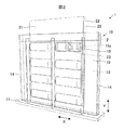
本発明の実施形態に係る制振装置について図面を参照しながら説明する。図1は、本実施形態の制振装置1を上側構造部材4および下側構造部材5に設置した状態を示し、図2は、第1の実施形態における制振装置1の斜視図であり、図3は、制振装置1の分解斜視図である。
A vibration damping device according to an embodiment of the present invention will be described with reference to the drawings. FIG. 1 shows a state in which the vibration damping device 1 of the present embodiment is installed on the upper structural member 4 and the lower
図1に示すように、制振装置1は、一対の鉛直柱3に橋架される上梁等の上側構造部材4および下梁等の下側構造部材5の間に設置される制振装置1である。一対の鉛直柱3、上側構造部材4、および下側構造部材5は、H型鋼またはI型鋼等により構成される。
As shown in FIG. 1, a vibration damping device 1 is installed between an upper structural member 4 such as an upper beam and a lower
図1−3に示すように、制振装置1は、容器10と、抵抗板20とを備える。
As illustrated in FIG. 1C, the vibration damping device 1 includes a
図2、3に示すように、容器10は、鋼材等により構成され、下側構造部材5にボルト等により固定された平板状の基部11と、基部11に立設され隙間を有して互いに対向する一対の第1の容器壁12および第2の容器壁13と、基部11に立設された一対の側壁14とを備える。容器10は、上部に開口10a(図4(a)を参照。)を有し、粘性体2が充填されている。粘性体2は、高粘度の高分子材料で構成され、その粘性抵抗力は速度依存性を有する。
As shown in FIGS. 2 and 3, the
第1の容器壁12は、平板状をなし、複数(本実施形態では8個)の第1の半円筒部15を有している(図2、図3においては、一つの第1の半円筒部15にのみ参照番号を付す。)。各第1の半円筒部15は、水平方向Xに沿って延び、水平方向Xに直交する断面が半円状をなし外方に凹む第1の凹部15a(図4も参照。)を有する。水平方向Xが所定の方向に相当する。
The
第2の容器壁13は、抵抗板20に関して第1の容器壁12と面対称の形状をなしている。すなわち、第2の容器壁13は、平板状をなし、複数(本実施形態では8個)の第2の半円筒部16を有している(図3においては、一つの第2の半円筒部16にのみ参照番号を付す。)。各第2の半円筒部16は、水平方向Xに沿って延び、水平方向Xに直交する断面が半円状をなし外方に凹む第2の凹部16a(図4(a)も参照。)を有する。
The
抵抗板20は、上側構造部材4に固定され、上側構造部材4から下側構造部材5に向かって延び、粘性体2に浸かるように開口10aを介して容器10内部に挿入されている。また、抵抗板20は、第1の容器壁12の各第1の半円筒部15の第1の凹部15aを閉じるように第1の容器壁12に近接対向する第1の主面21と、第1の主面21に対し反対側に位置し、第2の容器壁13の各第2の半円筒部16の第2の凹部16aを閉じるように第2の容器壁13に近接対向する第2の主面22とを有する。
The
抵抗板20の第1の主面21側には、複数の第1の半円筒部15に対応して、複数の第1の凸部23が設けれ、各第1の凸部23は、各第1の半円筒部15の第1の凹部15a内に突出するように設けられている(図2においては、一つの第1の凸部23にのみ参照番号を付す。)。抵抗板20の第2の主面22側には、複数の第2の半円筒部16に対応して、複数の第2の凸部24が設けれ(図4(a)を参照。)、各第2の凸部24は、各第2の半円筒部16の第2の凹部16a内に突出するように設けられている。
On the first
このような構成により、第1の容器壁12の各第1の半円筒部15の第1の凹部15aおよび抵抗板20の対応する第1の凸部23によって、簡易的なシリンダ−ピストン機構が構成され、同様に第2の容器壁13の各第2の半円筒部16の第2の凹部16aおよび抵抗板20の対応する第2の凸部24によって、簡易的なシリンダ−ピストン機構が構成される。
With such a configuration, a simple cylinder-piston mechanism is realized by the first
また、第1の凸部23および第2の凸部24は、抵抗板20に対し、鉛直方向Yに変位可能に設けられている。図4を参照して、第1の凸部23および第2の凸部24が、抵抗板20に対し、変位可能な構成について説明する。
The
図4(a)は、第1の容器壁12、第2の容器壁13、および抵抗板20を第1の凸部23及び第2の凸部24の位置で水平方向Xに直交する平面で切った断面図であり、図4(b)は、図4(a)のVB−VB線に沿った断面図である。
4A is a plane in which the
図4(a)に示すように、抵抗板20には貫通孔20aが形成されている。貫通孔20aには、挿入孔25aが形成された環状の環状部材25が配置されている。環状部材25の奥行方向Z(水平方向Xおよび鉛直方向Yに直交する方向)の長さは、抵抗板20の厚さよりも長く構成され、両端部はそれぞれ第1の主面21および第2の主面22から突出している。そして、環状部材25の第1の主面21から突出する部分が第1の凸部23に相当し、環状部材25の第2の主面22から突出する部分が第2の凸部24に相当する。
As shown in FIG. 4A, the
また、貫通孔20aの鉛直方向Yの幅は、環状部材25の鉛直方向Yの幅よりも長く構成されている。また、環状部材25の挿通孔25aには、第1の主面21に固定された支持部材26および第2の主面22に固定された支持部材27が挿入されている。支持部材26、27の挿通穴25aに挿入されている部分の鉛直方向Yの幅は、環状部材25の挿通穴25aの鉛直方向Yの幅よりも短く構成されている。よって、環状部材25は、支持部材26、27に対し鉛直方向Yに変位可能である。
Further, the width in the vertical direction Y of the through
このように、貫通孔20aの鉛直方向Yの幅は、環状部材25の鉛直方向Yの幅よりも長く構成され、環状部材25は、支持部材26、27により鉛直方向Yに変位可能に支持されている。よって、環状部材25(第1の凸部23および第2の凸部24)は、抵抗板20に対し、鉛直方向Yに変位可能に設けられている。
Thus, the width of the through
図4(a)、(b)に示すように、第1の容器壁12の第1の凹部15aと、抵抗板20の第1の凸部23との間には、隙間Gが形成されている。図4(b)に示すように、第1の半円筒部15の第1の凹部15aおよび第1の主面21により画成された略密閉空間6は、抵抗板20の第1の凸部23により2つの空間6a、6bに区画されている。同様に、第2の容器壁13の第2の凹部16aと、抵抗板20の第2の凸部24との間には、隙間Gが形成されている。図4(b)に示すように、第2の半円筒部16の第2の凹部16aおよび第2の主面22により画成された略密閉空間4は、抵抗板20の第2の凸部27により2つの空間7a、7bに区画されている。
As shown in FIGS. 4A and 4B, a gap G is formed between the first
次に、制振装置1による振動の減衰動作について、図1、2、4を参照して説明する。 Next, the vibration damping operation by the vibration damping device 1 will be described with reference to FIGS.
例えば、地震が発生すると、上側構造部材4が、下側構造部材5に対し水平方向Xに相対的に変位する。これに伴い、抵抗板20が、容器10に対し水平方向Xに相対的に変位する。
For example, when an earthquake occurs, the upper structural member 4 is displaced relative to the lower
これにより、抵抗板20の各第1の凸部23が、第1の容器壁12の対応する第1の凹部15a内を移動する。抵抗板20の各第1の凸部23の移動によって、粘性体2が2つの空間6a、6bを隙間Gを介して移動する。粘性体2が隙間Gを通過することにより、大きな粘性抵抗力が発生し、振動が減衰される。同様に、抵抗板20の各第2の凸部24が、第2の容器壁13の対応する第2の凹部16a内を移動する。抵抗板20の各第2の凸部24の移動によって、粘性体2が2つの空間7a、7bを隙間Gを介して移動する。粘性体2が隙間Gを通過することにより、大きな粘性抵抗力が発生し、振動が減衰される。
Thereby, each 1st
また、上側構造部材4および下側構造部材5が一対の支柱3に橋架されているので、上側構造部材4が、下側構造部材5に対し水平方向Xに相対的に変位するすると、上側構造部材4は、鉛直方向Yにもわずかに変位する。これにより、上側構造部材4に固定された抵抗板20も鉛直方向Yにわずかに変位する。各第1の凸部23および各第2の凸部24は、抵抗板20に対し、鉛直方向Yに変位可能に設けられているので、抵抗板20が鉛直方向Yに変位したとしても、水平方向Xに沿って延びる各第1の凹部15aおよび各第2の凹部16a内を滑らかに移動する。
In addition, since the upper structural member 4 and the lower
また、速度依存性を有する粘性体2は、抵抗板20の第1の凸部23および第2の凸部24の変位速度に応じた粘性抵抗力を発生する。すなわち、抵抗板20の第1の凸部23および第2の凸部24が、第1の容器壁12および第2の容器壁13に対し相対的に高速で変位しようとすると、粘性体2は大きな粘性抵抗力を発生する。このように、抵抗板20の第1の凸部23および第2の凸部24が、第1の容器壁12および第2の容器壁13に対し相対的に高速に変位するときは、大きな粘性抵抗力により振動を減衰させることができる。
Further, the
一方、抵抗板20の第1の凸部23および第2の凸部24が、第1の容器壁12および第2の容器壁13に対し低速で変位するときは、粘性体2は大きな粘性抵抗力を発生しない。
On the other hand, when the first
以上のように、本実施形態の制振装置1では、第1の容器壁12には、外方に凹み水平方向に延びる第1の凹部15aが形成され、抵抗板20の第1の主面21は、第1の凹部15aを閉じるように第1の容器壁12に対向し、第1の主面21から第1の凹部15a内に突出する第1の凸部23が設けられている。
As described above, in the vibration damping device 1 of the present embodiment, the
このような構成により、第1の容器壁12の第1の半円筒部15の第1の凹部15aおよび抵抗板20の第1の凸部23によって、簡易的なシリンダ−ピストン機構が構成される。
With such a configuration, a simple cylinder-piston mechanism is configured by the first
そして、地震発生時に、上側構造部材4が、下側構造部材5に対し水平方向Xに相対的に変位することに伴い、抵抗板20が、容器10に対し水平方向Xに相対的に変位する。その結果、抵抗板20の第1の凸部23が、第1の容器壁12の第1の凹部15a内を移動し、粘性体2が第1の凹部15a内を流動することにより、大きな粘性抵抗力が発生する。このように、簡易的なシリンダ−ピストン機構が構成し、当該シリンダ−ピストン機構を作動させることにより、大きな粘性抵抗力を発生させることができ、振動を減衰させることができる。
Then, when the upper structural member 4 is displaced relative to the lower
また、第1の容器壁12の第1の凹部15aと、抵抗板20の第1の凸部23との間には、隙間Gが形成されている。よって、抵抗板20の第1の凸部23の移動によって、粘性体2が2つの空間3a、3bを隙間Gを介して移動し、当該粘性体2の移動により、大きな粘性抵抗力が発生し、振動を減衰させることができる。
Further, a gap G is formed between the first
また、第1の容器壁12の第1の凹部15aは、水平方向に沿って延びるように形成され、抵抗板20の第1の凸部23は、抵抗板20に対し、鉛直方向Yに変位可能に設けられている。よって、一対の支柱3に橋架されている上側構造部材4が、下側構造部材5に対する相対的に変位により、鉛直方向Yに変位し、上側構造部材4に固定された抵抗板20が鉛直方向Yに変位したとしても、第1の凸部23は、抵抗板20に対し、鉛直方向Yに変位可能に設けられているので、水平方向Xに沿って延びる第1の凹部15a内を滑らかに移動することができる。
The first
また、第2の容器壁13には、外方に凹み水平方向に延びる第2の凹部16aが形成され、抵抗板20の第2の主面22は、第2の凹部16aを閉じるように第2の容器壁13に対向し、第2の主面22から第2の凹部16a内に突出する第2の凸部24が設けられている。
Further, the
このような構成により、第2の容器壁13の第2の半円筒部16の第2の凹部16aおよび抵抗板20の第2の凸部24によって、簡易的なシリンダ−ピストン機構が構成される。よって、上記と同様に当該シリンダ−ピストン機構を作動させることにより、抵抗板20の両面において、粘性体2に大きな粘性抵抗力を発生させることができ、振動を減衰させることができる。
With such a configuration, a simple cylinder-piston mechanism is configured by the second
また、第1の容器壁12の第1の凹部15aおよび第2の容器壁13の第2の凹部16aは、それぞれ複数形成され、抵抗板20の第1の凸部23および第2の凸部24は、複数の第1の凹部15aおよび複数の第2の凹部16aに対応して複数設けられている。よって、各第1の凸部23および第2の凸部24が対応する各第1の凹部15aおよび各第2の凹部16aに対して相対的に移動することにより、粘性体2にさらに大きな粘性抵抗力を発生させることができる。
A plurality of
なお、本発明は、上述した実施例に限定されない。当業者であれば、本発明の範囲内で、種々の追加や変更等を行うことができる。 In addition, this invention is not limited to the Example mentioned above. A person skilled in the art can make various additions and changes within the scope of the present invention.
例えば、上記の実施形態では、各第1の凸部23および各第2の凸部24は、抵抗板20に対し、鉛直方向Yに変位可能に設けられていた。しかし、図5に示すように、第1の凸部123および第2の凹部(図5には図示せず)は、抵抗板20に対し移動不能に固定されていても良い。当該構成では、上側構造部材4の下部構造部材5に対する相対的な変位により、第1の凸部123および第2の凸部は、その軌跡が湾曲状をなすように変位する。これに伴い、第1の容器壁12の第1の半円筒部115の第1の凹部115aは、第1の凹部123の湾曲状の変位の軌跡に応じて、湾曲状に形成しても良い。なお、図示しないが、第2の容器壁13の第2の半円筒部の第2の凹部も、第2の凸部の湾曲状の変位の軌跡に応じて、湾曲状に形成しても良い。
For example, in the above embodiment, each
当該構成によっても、第1の容器壁12の第1の半円筒部115の第1の凹部115aおよび抵抗板20の第1の凸部123によって、簡易的なシリンダ−ピストン機構が構成され、第2の容器壁13の第2の半円筒部の第2の凹部および抵抗板20の第2の凸部によって、簡易的なシリンダ−ピストン機構が構成される。
Also in this configuration, a simple cylinder-piston mechanism is configured by the first
そして、地震発生時に、上側構造部材4が、下側構造部材5に対し水平方向Xに相対的に変位することに伴い、抵抗板20が、容器10に対し水平方向Xに相対的に変位する。その結果、抵抗板20の第1の凸部23が、第1の容器壁12の第1の凹部15a内を移動し、粘性体2が第1の凹部15a内を流動することにより、大きな粘性抵抗力が発生する。このように、簡易的なシリンダ−ピストン機構が構成し、当該シリンダ−ピストン機構を作動させることにより、粘性体2に大きな粘性抵抗力を発生させることができ、振動を減衰させることができる。
Then, when the upper structural member 4 is displaced relative to the lower
また、上記の実施形態では、第1の容器壁12の各第1の半円筒部15の第1の凹部15aおよび第2の容器壁13の各第2の半円筒部16の第2の凹部16aは、それぞれ水平方向Xに沿って延びるように形成されていたが、鉛直方向Yに沿って延びるように形成されても良い。また、抵抗板20の第1の凸部23および第2の凸部24の形状は、鉛直方向Yに延びる第1の凹部15aおよび第2の凹部16aに対応した形状となる。なお、この場合、鉛直方向Yが所定の方向に相当する。
In the above embodiment, the first
当該構成の制振装置によれば、大型車両等の走行により建造物が鉛直方向Yに振動し、上側構造部材4および下側構造部材5が鉛直方向Yに相対的に変位した場合に、抵抗板20の第1の凹部23および第2の凹部24が、鉛直方向Yに延びる第1の凹部および第2の凹部内を移動する。これにより、粘性体2が第1の凹部および第2の凹部内を流動し、粘性抵抗力が発生するので、鉛直方向Yの揺れを減衰させることができ、建造物内にいる人に震動が伝わるのを抑制することができる。
According to the vibration damping device of the configuration, when the building vibrates in the vertical direction Y by traveling of a large vehicle or the like, the resistance is increased when the upper structural member 4 and the lower
また、上記の実施の形態の第1の容器壁12の各第1の半円筒部15の第1の凹部15aおよび第2の容器壁13の各第2の半円筒部16の第2の凹部16aは、それらの水平方向の中央部の上下に、外方に凹む凹部を有しても良い。かかる構成によれば、水平方向Xの揺れおよび鉛直方向Yの揺れを減衰させることができる。
The
また、上記の実施形態では、制振装置1を建物内の一対の鉛直柱3に橋架される上梁等の上側構造部材4および下梁等の下側構造部材5の間に設置した形態について説明したが、制振装置1を斜張橋ケーブルの振動を減衰するためのケーブルダンパとして使用しても良い。この場合において、容器10は斜張橋の橋桁に取り付けられ、抵抗板20は斜張橋ケーブルに取り付けられる。また、斜張橋ケーブルは塔と橋桁との間を斜めに張られているので、これに合わせて、第1の容器壁12の第1の半円筒部15(第1の凹部15a)および第2の容器壁13の第2の半円筒部16(第2の凹部16a)は、斜め方向(水平方向Xおよび鉛直方向Yに交差し第1の主面21に平行な方向)に延びるように形成される。また、抵抗板20の第1の凸部23および第2の凸部24の形状は、斜め方向に延びる第1の凹部15aおよび第2の凹部16aに対応した形状となる。なお、この場合、斜め方向(水平方向Xおよび鉛直方向Yに交差し第1の主面21に平行な方向)が所定の方向に相当する。
In the above embodiment, the vibration damping device 1 is installed between the upper structural member 4 such as the upper beam and the lower
当該構成の制振装置によれば、斜張橋ケーブル振動が発生した場合、抵抗板20が、容器10に対し斜め方向に相対的に変位する。その結果、抵抗板20の第1の凸部23および第2の凸部24が、第1の容器壁12の第1の凹部15a内および第2の容器壁13の第2の凹部16a内を移動し、粘性体2が第1の凹部15a内および第2の凹部16a内を流動することにより、大きな粘性抵抗力が発生する。このように、大きな粘性抵抗力を発生させることができ、斜張橋ケーブル振動を減衰させることができる。なお、抵抗板20が容器10に対し斜め方向以外の方向にも変位するため、抵抗板20の第1の凸部23および第2の凸部24を第1の容器壁12の第1の凹部15aおよび第2の容器壁13の第2の凹部16aに対して、変位に必要な隙間を有するように構成する。
According to the vibration damping device having the above configuration, when the cable stayed bridge vibration occurs, the
また、上記の実施形態では、第1の容器壁12の第1の凹部15aと、抵抗板20の第1の凸部23との間、第1の容器壁12の第1の凹部15aと、抵抗板20の第1の凸部23との間に隙間Gを形成して、当該隙間Gに粘性体2を通過させて、粘性抵抗が発生するようにした。しかし、隙間Gを形成せずに、第1の凸部23および第2の凸部24に貫通孔またはスリットを形成して、粘性体2が貫通孔またはスリットを通過することにより粘性抵抗が発生する構成にしても良い。
Moreover, in said embodiment, between the 1st recessed
また、第1の容器壁12の第1の凹部15aおよび第2の容器壁13の第2の凹部16aの断面は半円状をなし、抵抗板20の第1の凸部23および第2の凸部24は当該半円状に対応する形状をなしていた。しかし、第1の容器壁12の第1の凹部15aおよび第2の容器壁13の第2の凹部16aの断面は三角形状、四角形状(矩形、台形等)であっても良く、抵抗板20の第1の凸部23および第2の凸部24は当該三角形状、四角形状(矩形、台形等)に対応する形状であっても良い。すなわち、第1の容器壁12の第1の凹部15aおよび第2の容器壁13の第2の凹部16aと、抵抗板20の第1の凸部23および第2の凸部24とは、互いに対応する形状をなしていればよい。
Further, the first
また、上記の実施形態では、第1の凹部15、第2の凹部16、第1の凸部23、および第2の凸部24は、複数設けられていたが、それらの数はいくつであっても良く、例えば1つであっても良い。また、第1の実施形態の抵抗板20における鉛直方向Yに変位可能な第1の凸部23および第2の凸部24を、第2の実施形態の抵抗板20に対し、第1の凸部123および第2の凸部に代えて設けても良い。また、上側構造部材4が水平方向に移動するのであれば、第2の実施形態の抵抗板20における第1の凸部123および第2の凸部を、第1の実施形態の抵抗板20に対し、第1の凸部23および第2の凸部24に代えて設けても良い。
In the above embodiment, a plurality of the first
1:制振装置、2:粘性体、 4:上側構造部材 5:下側構造部材、10:容器、10a:開口、12:第1の容器壁、13:第2の容器壁、15a:第1の凹部、16a:第2の凹部、20:抵抗板、21:第1の主面、22:第2の主面、23:第1の凸部、24:第2の凸部、G:隙間
1: damping device, 2: viscous body, 4: upper structural member, 5: lower structural member, 10: container, 10a: opening, 12: first container wall, 13: second container wall, 15a: first 1 concave portion, 16a: second concave portion, 20: resistance plate, 21: first main surface, 22: second main surface, 23: first convex portion, 24: second convex portion, G: Gap
Claims (7)
前記下側構造部材に固定され、上部に開口を有し、隙間を介して互いに対向する一対の第1の容器壁および第2の容器壁を備え、粘性体を収容する容器と、
前記上側構造部材に固定され、前記開口から前記容器内部に挿入された抵抗板と、を備え、
前記第1の容器壁には、外方に凹み所定の方向に延びる第1の凹部が形成され、
前記抵抗板は、前記第1の容器壁に近接対向する第1の主面と、前記第1の主面側に設けられ前記第1の凹部内に突出する第1の凸部と、前記第1の主面に対し反対側に位置し前記第2の容器壁に対向する第2の主面とを有し、
前記第1の容器壁の前記第1の凹部は、水平方向に沿って延びるように形成され、
前記抵抗板の前記第1の凸部は、前記第1の主面に対し、鉛直方向に移動可能に設けられている制振装置。 A vibration damping device installed between the upper structural member and the lower structural member located below the upper structural member,
A container that is fixed to the lower structural member, has an opening in the upper part, and includes a pair of first container wall and second container wall that face each other via a gap, and contains a viscous body;
A resistor plate fixed to the upper structural member and inserted into the container from the opening;
The first container wall is formed with a first recess recessed outward and extending in a predetermined direction,
The resistance plate includes a first main surface that is proximately opposed to the first container wall, a first convex portion that is provided on the first main surface side and protrudes into the first concave portion, and the first located on the opposite side have a second major surface facing the second container wall with respect to the first main surface,
The first recess of the first container wall is formed to extend along a horizontal direction;
The damping device provided with the 1st convex part of the resistance board so that movement in the perpendicular direction is possible to the 1st principal surface .
前記下側構造部材に固定され、上部に開口を有し、隙間を介して互いに対向する一対の第1の容器壁および第2の容器壁を備え、粘性体を収容する容器と、 A container that is fixed to the lower structural member, has an opening in the upper part, and includes a pair of first container wall and second container wall that face each other via a gap, and contains a viscous body;
前記上側構造部材に固定され、前記開口から前記容器内部に挿入された抵抗板と、を備え、 A resistor plate fixed to the upper structural member and inserted into the container from the opening;
前記第1の容器壁には、外方に凹み所定の方向に延びる第1の凹部が形成され、 The first container wall is formed with a first recess recessed outward and extending in a predetermined direction,
前記抵抗板は、前記第1の容器壁に近接対向する第1の主面と、前記第1の主面側に設けられ前記第1の凹部内に突出する第1の凸部と、前記第1の主面に対し反対側に位置し前記第2の容器壁に対向する第2の主面とを有し、 The resistance plate includes a first main surface that is proximately opposed to the first container wall, a first convex portion that is provided on the first main surface side and protrudes into the first concave portion, and the first A second main surface located opposite to the main surface of the first surface and facing the second container wall;
前記抵抗板の前記第1の凸部は、前記第1の主面に対し移動不能に設けられ、前記上側構造部材の前記下部構造部材に対する相対的な変位に応じて、軌跡が湾曲状をなすように変位し、 The first convex portion of the resistance plate is provided so as not to move with respect to the first main surface, and a locus is curved according to a relative displacement of the upper structural member with respect to the lower structural member. Is displaced as
前記第1の容器壁の前記第1の凹部は、前記抵抗板の前記第1の凸部の変位に応じて湾曲状に形成されている制振装置。 The vibration damping device in which the first concave portion of the first container wall is formed in a curved shape according to the displacement of the first convex portion of the resistance plate.
前記下側構造部材に固定され、上部に開口を有し、隙間を介して互いに対向する一対の第1の容器壁および第2の容器壁を備え、粘性体を収容する容器と、 A container that is fixed to the lower structural member, has an opening in the upper part, and includes a pair of first container wall and second container wall that face each other via a gap, and contains a viscous body;
前記上側構造部材に固定され、前記開口から前記容器内部に挿入された抵抗板と、を備え、 A resistor plate fixed to the upper structural member and inserted into the container from the opening;
前記第1の容器壁には、外方に凹み所定の方向に延びる第1の凹部が形成され、 The first container wall is formed with a first recess recessed outward and extending in a predetermined direction,
前記抵抗板は、前記第1の容器壁に近接対向する第1の主面と、前記第1の主面側に設けられ前記第1の凹部内に突出する第1の凸部と、前記第1の主面に対し反対側に位置し前記第2の容器壁に対向する第2の主面とを有し、 The resistance plate includes a first main surface that is proximately opposed to the first container wall, a first convex portion that is provided on the first main surface side and protrudes into the first concave portion, and the first A second main surface located opposite to the main surface of the first surface and facing the second container wall;
前記第1の容器壁の前記第1の凹部は、水平方向および鉛直方向に対して傾斜し前記第1の主面に平行な方向に沿って延びるように形成されている制振装置。 The vibration damping device, wherein the first recess of the first container wall is formed so as to incline with respect to a horizontal direction and a vertical direction and extend along a direction parallel to the first main surface.
前記第2の主面は、前記第2の容器壁に近接対向し、
前記抵抗板は、前記第2の主面側に設けられ前記第2の凹部内に突出する第2の凸部を有する請求項1から請求項3のいずれか一項に記載の制振装置。 The second container wall is formed with a second recess recessed outward and extending in the predetermined direction,
The second main surface is in close proximity to the second container wall,
The said resistance board is a damping device as described in any one of Claims 1-3 which has a 2nd convex part which is provided in the said 2nd main surface side and protrudes in the said 2nd recessed part.
前記第2の凹部は、前記第2の容器壁に複数形成され、
前記第1の凸部は、複数の前記第1の凹部に対応して前記抵抗板に複数設けられ、
前記第2の凸部は、複数の前記第2の凹部に対応して前記抵抗板に複数設けられている請求項6に記載の制振装置。 A plurality of the first recesses are formed in the first container wall;
A plurality of the second recesses are formed in the second container wall;
A plurality of the first protrusions are provided on the resistance plate corresponding to the plurality of first recesses,
The vibration control device according to claim 6 , wherein a plurality of the second protrusions are provided on the resistance plate corresponding to the plurality of second recesses.
Priority Applications (1)
| Application Number | Priority Date | Filing Date | Title |
|---|---|---|---|
| JP2014248613A JP6470027B2 (en) | 2014-12-09 | 2014-12-09 | Vibration control device |
Applications Claiming Priority (1)
| Application Number | Priority Date | Filing Date | Title |
|---|---|---|---|
| JP2014248613A JP6470027B2 (en) | 2014-12-09 | 2014-12-09 | Vibration control device |
Publications (2)
| Publication Number | Publication Date |
|---|---|
| JP2016109236A JP2016109236A (en) | 2016-06-20 |
| JP6470027B2 true JP6470027B2 (en) | 2019-02-13 |
Family
ID=56122050
Family Applications (1)
| Application Number | Title | Priority Date | Filing Date |
|---|---|---|---|
| JP2014248613A Active JP6470027B2 (en) | 2014-12-09 | 2014-12-09 | Vibration control device |
Country Status (1)
| Country | Link |
|---|---|
| JP (1) | JP6470027B2 (en) |
Family Cites Families (6)
| Publication number | Priority date | Publication date | Assignee | Title |
|---|---|---|---|---|
| JPS5443263Y2 (en) * | 1976-07-02 | 1979-12-14 | ||
| JPS60126507U (en) * | 1984-02-01 | 1985-08-26 | オイレス工業株式会社 | shock absorber |
| JP2777916B2 (en) * | 1989-09-08 | 1998-07-23 | 川田工業株式会社 | Cable damper for cable stayed bridge |
| JPH11101020A (en) * | 1997-09-29 | 1999-04-13 | Oiles Ind Co Ltd | Earthquake damping device and earthquake damping wall using the same |
| JPH11241526A (en) * | 1998-02-24 | 1999-09-07 | Sumitomo Constr Co Ltd | Seismic control wall and its attaching method, and seismic control structure using its wall |
| JP2002295051A (en) * | 2001-03-28 | 2002-10-09 | Nippon Steel Corp | Viscous wall |
-
2014
- 2014-12-09 JP JP2014248613A patent/JP6470027B2/en active Active
Also Published As
| Publication number | Publication date |
|---|---|
| JP2016109236A (en) | 2016-06-20 |
Similar Documents
| Publication | Publication Date | Title |
|---|---|---|
| KR101186448B1 (en) | Lintel beam type hysteretic damper using interstory drift of rahmen frame | |
| KR20130027786A (en) | Shear wall type vibration control apparatus | |
| JP6470027B2 (en) | Vibration control device | |
| JP2014194116A (en) | Vibration control structure of building | |
| JP6794133B2 (en) | building | |
| JP5994750B2 (en) | Damping structure | |
| JP2006257688A (en) | Vibration damping type bolt connection structure | |
| JP4676797B2 (en) | Vibration control device | |
| JP5720718B2 (en) | Vibration control building | |
| JP7225511B2 (en) | Damping structure | |
| JP6303492B2 (en) | Damping structure | |
| JP6756441B2 (en) | Vibration damping device and vibration damping structure of structure | |
| JP6411297B2 (en) | Damping damper | |
| JP2016090034A (en) | Vibration control device | |
| JP6318609B2 (en) | Damping structure | |
| JP2000064655A (en) | Vibration control device for structure | |
| JP7257747B2 (en) | Damping structure | |
| JP5771650B2 (en) | Damping damper | |
| JP4705759B2 (en) | Damping walls and structures | |
| JP5447974B2 (en) | Damping floor beam | |
| JPH06136718A (en) | Cable damper | |
| JP6545533B2 (en) | Vibration control device | |
| KR102158636B1 (en) | A Rotary Horizontal Vibration Damping System Using Mass and Wire | |
| JP2020079495A (en) | Vibration control structure | |
| JP2022110464A (en) | Vibration control structure |
Legal Events
| Date | Code | Title | Description |
|---|---|---|---|
| A621 | Written request for application examination |
Free format text: JAPANESE INTERMEDIATE CODE: A621 Effective date: 20171205 |
|
| A977 | Report on retrieval |
Free format text: JAPANESE INTERMEDIATE CODE: A971007 Effective date: 20181011 |
|
| A131 | Notification of reasons for refusal |
Free format text: JAPANESE INTERMEDIATE CODE: A131 Effective date: 20181023 |
|
| A521 | Request for written amendment filed |
Free format text: JAPANESE INTERMEDIATE CODE: A523 Effective date: 20181126 |
|
| TRDD | Decision of grant or rejection written | ||
| A01 | Written decision to grant a patent or to grant a registration (utility model) |
Free format text: JAPANESE INTERMEDIATE CODE: A01 Effective date: 20181225 |
|
| A61 | First payment of annual fees (during grant procedure) |
Free format text: JAPANESE INTERMEDIATE CODE: A61 Effective date: 20190117 |
|
| R150 | Certificate of patent or registration of utility model |
Ref document number: 6470027 Country of ref document: JP Free format text: JAPANESE INTERMEDIATE CODE: R150 |
|
| R250 | Receipt of annual fees |
Free format text: JAPANESE INTERMEDIATE CODE: R250 |
|
| R250 | Receipt of annual fees |
Free format text: JAPANESE INTERMEDIATE CODE: R250 |
|
| R250 | Receipt of annual fees |
Free format text: JAPANESE INTERMEDIATE CODE: R250 |