JP6469486B2 - Bathing equipment - Google Patents
Bathing equipment Download PDFInfo
- Publication number
- JP6469486B2 JP6469486B2 JP2015052678A JP2015052678A JP6469486B2 JP 6469486 B2 JP6469486 B2 JP 6469486B2 JP 2015052678 A JP2015052678 A JP 2015052678A JP 2015052678 A JP2015052678 A JP 2015052678A JP 6469486 B2 JP6469486 B2 JP 6469486B2
- Authority
- JP
- Japan
- Prior art keywords
- stretcher
- bathtub
- frame
- nursing
- bathing
- Prior art date
- Legal status (The legal status is an assumption and is not a legal conclusion. Google has not performed a legal analysis and makes no representation as to the accuracy of the status listed.)
- Active
Links
- 238000003287 bathing Methods 0.000 title claims description 69
- 230000000474 nursing effect Effects 0.000 claims description 67
- 230000007246 mechanism Effects 0.000 claims description 27
- 239000000463 material Substances 0.000 claims description 7
- 230000008878 coupling Effects 0.000 claims description 6
- 238000010168 coupling process Methods 0.000 claims description 6
- 238000005859 coupling reaction Methods 0.000 claims description 6
- 230000003028 elevating effect Effects 0.000 claims description 4
- XLYOFNOQVPJJNP-UHFFFAOYSA-N water Substances O XLYOFNOQVPJJNP-UHFFFAOYSA-N 0.000 claims description 4
- 210000002414 leg Anatomy 0.000 description 25
- 101150114468 TUB1 gene Proteins 0.000 description 22
- 238000009434 installation Methods 0.000 description 3
- 238000003825 pressing Methods 0.000 description 3
- 238000004804 winding Methods 0.000 description 3
- 230000009471 action Effects 0.000 description 2
- 229910052782 aluminium Inorganic materials 0.000 description 2
- XAGFODPZIPBFFR-UHFFFAOYSA-N aluminium Chemical compound [Al] XAGFODPZIPBFFR-UHFFFAOYSA-N 0.000 description 2
- 239000000470 constituent Substances 0.000 description 1
- 210000003414 extremity Anatomy 0.000 description 1
- 230000006872 improvement Effects 0.000 description 1
- 210000003127 knee Anatomy 0.000 description 1
- 239000007769 metal material Substances 0.000 description 1
- 238000000034 method Methods 0.000 description 1
- 239000002990 reinforced plastic Substances 0.000 description 1
- 229910001220 stainless steel Inorganic materials 0.000 description 1
- 239000010935 stainless steel Substances 0.000 description 1
- 230000032258 transport Effects 0.000 description 1
- 238000005406 washing Methods 0.000 description 1
- 239000013585 weight reducing agent Substances 0.000 description 1
- 238000003466 welding Methods 0.000 description 1
Images


Description
本発明は、介護が必要とされる人を入浴させるための入浴装置に関する。 The present invention relates to a bathing apparatus for bathing a person who needs care.
身障者や介護を必要とする老人等の要介護者を入浴させる介護サービスが広く行われている。在宅の要介護者に対しては、介護用浴槽を要介護者の住居に運搬して要介護者を入浴させる訪問入浴サービスが行われている。また、養護老人ホーム等の介護施設の要介護者に対しては、介護施設の介護従事者による入浴サービスが行われている。 Nursing care services are widely available for bathing people requiring care, such as the disabled and elderly people who need nursing care. For home care recipients, there is a visiting bath service that transports the care tub to the home of the care recipient and bathes the care recipient. In addition, bathing services are provided to care recipients in nursing homes such as nursing homes for the elderly.
このような入浴サービスにおいて、要介護者を入浴させる際に、要介護者の入浴を円滑に行うため、また、介護従事者の作業負担を軽減するための入浴装置が提供されている。このような入浴装置としては、要介護者を乗せるための入浴用担架を備え、入浴用担架の高さを調整可能に構成された移動式の入浴用ストレッチャーが知られている(例えば、特許文献1参照)。この特許文献1の入浴用ストレッチャーは、前後左右にキャスターを備えた4つの脚部を有しており、この4つの脚部で囲まれたスペースに介護用浴槽を配置可能に構成されている。 In such a bathing service, a bathing apparatus is provided for smoothly bathing a care recipient and reducing the work burden on a caregiver when bathing a care recipient. As such a bathing apparatus, there is known a mobile bath stretcher that includes a bath stretcher for carrying a care recipient and is configured to be able to adjust the height of the bath stretcher (for example, a patent) Reference 1). The stretcher for bathing of this patent document 1 has four legs provided with casters on the front, rear, left and right, and is configured such that a nursing tub can be arranged in a space surrounded by the four legs. .
かかる入浴用ストレッチャーは、以下のようにして用いられる。まず、入浴用担架の位置を介護用浴槽よりも高くした状態で、要介護者を入浴用担架に乗せる。次に、入浴用担架が、湯をはった状態の介護用浴槽の上側に位置するように、入浴用ストレッチャーを移動させる。その後、入浴用担架の位置を下げて要介護者を入浴させる。 Such a bath stretcher is used as follows. First, in the state where the position of the stretcher for bathing is higher than that of the bathtub for nursing care, the care recipient is placed on the stretcher for bathing. Next, the stretcher for bathing is moved so that the stretcher for bathing is positioned on the upper side of the care bathtub with hot water. Then, the position of the bath stretcher is lowered and the care recipient is bathed.
しかしながら、このような入浴用ストレッチャーは、4つの脚部で囲まれたスペースに介護用浴槽を配置可能にするため、前後左右の幅(長さ)を介護用浴槽よりも大きくする必要がある。そのため、訪問入浴サービスを行う際には、要介護者の住居のドアのサイズによっては、入浴用ストレッチャーを住居内に運搬することができない。また、介護施設では、入浴用ストレッチャーを施設内のエレベータに載せづらかったり、エレベータの寸法によっては、載せられない場合もある。 However, such a bath stretcher needs to make the width (length) of the front, rear, right and left larger than that of the nursing tub so that the nursing tub can be arranged in a space surrounded by four legs. . Therefore, when performing a visit bathing service, depending on the size of the door of the residence of the care recipient, the bath stretcher cannot be carried into the residence. Moreover, in a nursing facility, it may be difficult to place a bath stretcher on an elevator in the facility, or depending on the size of the elevator.
さらに、介護施設における浴場には、複数の介護用浴槽が設置されており、また、前述したような幅広で、かつ長尺な入浴用ストレッチャーが介護用浴槽間の通路を通れるようにする必要がある。すなわち、介護施設内の浴場としては、十分なスペースを有する部屋が用いられる。しかしながら、小規模の介護施設等では、十分なスペースの浴場を施設内に持つことができない場合があるため、浴場の省スペース化を図りつつ、多くの要介護者を効率良く入浴させるための方法が求められている。 In addition, there are a plurality of nursing tubs installed in the bathing area in the nursing facility, and a wide and long bath stretcher as described above needs to be able to pass through the passage between the nursing tubs. There is. That is, a room having sufficient space is used as a bathhouse in a nursing facility. However, in small-scale care facilities, etc., there may be cases where there is not enough bath space in the facility, so a method for efficiently bathing many care recipients while saving space in the bath space. Is required.
本発明は、上記従来の問題点を鑑みたものであり、その目的は、設置スペースを抑えて省スペース化を図りつつ、利便性に優れた入浴装置を提供することにある。 The present invention has been made in view of the above-described conventional problems, and an object of the present invention is to provide a bathing apparatus excellent in convenience while reducing installation space and saving space.
このような目的は以下の特徴(1)〜(7)を有する本発明により達成される。
(1) 底部および前記底部から立設された側壁部で形成される空間に湯を貯めるように構成された平面視略長方形状の浴槽本体と、前記側壁部の長手方向両側のそれぞれの上端部から前記浴槽本体の外側に張り出したリム部と、を備えた介護用浴槽と、
前記リム部を介して前記介護用浴槽を着脱自在に支持可能な一対の浴槽受け部を有するフレームを備え、走行可能に構成されたストレッチャーと、
前記介護用浴槽上に配置されるように前記フレームに支持され、入浴者を乗せて入浴させるための担架シートとを有し、
前記リム部は、前記側壁部の前記長手方向両側の前記上端部から前記浴槽本体の外側に延出する第1の片部と、前記第1の片部の前記側壁部と反対側の端部から下側に延出する第2の片部とで構成され、前記リム部の断面形状は、略L字状をなしていることを特徴とする入浴装置。
Such an object is achieved by the present invention having the following features (1) to ( 7 ).
(1) A substantially rectangular bathtub main body configured to store hot water in a space formed by a bottom portion and a side wall portion standing from the bottom portion, and upper end portions on both sides in the longitudinal direction of the side wall portion and nursing bathtubs and a rim portion protruding to the outside of the bathtub body from
A stretcher that includes a frame having a pair of bathtub receiving portions that can removably support the nursing tub through the rim portion;
The supported by the frame so as to be disposed nursing on bath, possess a stretcher sheet for bathing put the bather,
The rim portion includes a first piece extending from the upper end on both sides in the longitudinal direction of the side wall to the outside of the bathtub body, and an end of the first piece opposite to the side wall. And a second piece portion extending downward from the rim portion, and the cross-sectional shape of the rim portion is substantially L-shaped .
(2) 前記担架シートは、その長手方向両側縁に形成された筒状部に挿通されるロープを介して前記フレームに支持されており、
前記ストレッチャーは、前記フレームに組み込まれ、前記ロープを巻き上げる巻上機構をさらに備えている上記(1)に記載の入浴装置。
(2) The stretcher sheet is supported by the frame via a rope inserted through a cylindrical portion formed on both side edges of the longitudinal direction,
The said stretcher is a bathing apparatus as described in said (1) further equipped with the winding mechanism integrated in the said frame and winding up the said rope.
(3) 前記フレームは、さらに、前記一対の浴槽受け部の一方の端部同士を連結する前方連結部と、前記一対の浴槽受け部の他方の端部同士を連結する後方連結部とを備えており、
前記担架シートは、その長手方向両側縁に形成された筒状部に挿通されるロープを介して前記前方連結部および前記後方連結部に支持されており、
前記前方連結部および前記後方連結部が、前記一対の浴槽受け部よりも高い位置に設けられることによって、前記担架シートは、前記介護用浴槽よりも高い位置に設けられ、
前記入浴者を前記担架シートに乗せた状態で、前記ロープが前記前方連結部および前記後方連結部から吊り下がることによって、前記担架シートが前記介護用浴槽内に位置する上記(1)または(2)に記載の入浴装置。
(3) The frame further includes a front connecting portion that connects one ends of the pair of bathtub receiving portions and a rear connecting portion that connects the other ends of the pair of bathtub receiving portions. And
The stretcher sheet is supported by the front connecting part and the rear connecting part via a rope inserted through a cylindrical part formed on both side edges of the longitudinal direction,
The front coupling portion and the rear coupling portion, the Rukoto which is positioned higher than the pair of bathtub receiving portion, said stretcher sheet, which is positioned higher than the nursing tub,
(1) or (2) in which the stretcher sheet is positioned in the nursing tub when the bather is placed on the stretcher sheet and the rope is suspended from the front connecting part and the rear connecting part. ) Bathing device.
(4) 前記介護用浴槽は、前記側壁部の短手方向両側の上端部から前記浴槽本体の外側に張り出した前方リム部および後方リム部を備えており、
前記介護用浴槽は、前記ストレッチャーの前記浴槽受け部に支持された状態において、前記前方リム部が前記ストレッチャーの前記前方連結部の下側に位置し、前記後方リム部が前記ストレッチャーの前記後方連結部の下側に位置する上記(3)に記載の入浴装置。
(4) The care tub includes a front rim portion and a rear rim portion projecting from the upper end portions on both sides in the short side direction of the side wall portion to the outside of the bathtub body ,
In the state where the nursing tub is supported by the bathtub receiving portion of the stretcher, the front rim portion is positioned below the front connecting portion of the stretcher, and the rear rim portion is of the stretcher. The bathing apparatus according to (3), which is located below the rear connection portion.
(5) 前記フレームは、前記前方連結部を含む第1の部分と、前記後方連結部を含む第2の部分とを備えており、
前記ストレッチャーは、前記フレームの前記第1の部分と前記第2の部分とが、前記前方連結部と前記後方連結部とが互いに近接するように、折り畳み可能に構成されている上記(3)または(4)に記載の入浴装置。
(5) The frame includes a first portion including the front connecting portion and a second portion including the rear connecting portion,
The stretcher is configured so that the first portion and the second portion of the frame can be folded so that the front connecting portion and the rear connecting portion are close to each other (3). Or the bathing apparatus as described in (4) .
(6) 前記ストレッチャーは、さらに、前記介護用浴槽の高さを調整可能に構成された昇降機構を備えている上記(1)ないし(5)のいずれかに記載の入浴装置。
(7) 前記介護用浴槽は、硬質FRP材料で形成されている上記(1)ないし(6)のいずれかに記載の入浴装置。
(6) The said stretcher is a bathing apparatus in any one of said (1) thru | or (5) provided with the raising / lowering mechanism comprised so that adjustment of the height of the said bathtub for care was further possible.
(7) The bathing apparatus according to any one of (1) to (6), wherein the nursing tub is formed of a hard FRP material.
以下、本発明の入浴装置を添付図面に示す好適な実施形態に基づいて説明する。
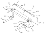
図1は、本発明の入浴装置の好適な実施形態の斜視図である。図2は、図1に示す入浴装置のストレッチャーの斜視図である。図3は、図1に示す入浴装置の側面図(介護用浴槽を2点鎖線で示す)である。
Hereinafter, the bathing apparatus of the present invention will be described based on preferred embodiments shown in the accompanying drawings.
FIG. 1 is a perspective view of a preferred embodiment of the bathing apparatus of the present invention. FIG. 2 is a perspective view of the stretcher of the bathing apparatus shown in FIG. FIG. 3 is a side view of the bathing apparatus shown in FIG. 1 (a nursing bath is indicated by a two-dot chain line).
なお、以下の説明では、図1〜図3中の上側を「上」または「上方」と言い、図1〜図3中の下側を「下」または「下方」と言う。また、図1および図2の紙面右手前側および図3の左側を「前方」または「入浴者の頭部側」と言い、図1および図2の紙面左奥側および図3の右側を「後方」または「入浴者の脚部側」と言う。 In the following description, the upper side in FIGS. 1 to 3 is referred to as “upper” or “upper”, and the lower side in FIGS. 1 to 3 is referred to as “lower” or “lower”. Also, the right front side of FIG. 1 and FIG. 2 and the left side of FIG. 3 are referred to as “front” or “the bather's head side”, and the left back side of FIG. 1 and FIG. "Or" the bather's leg side ".
図1に示すように、本実施形態の入浴装置100は、介護用浴槽1と、介護用浴槽1を着脱自在に取り付けられるストレッチャー2と、介護用浴槽1上に配置され、入浴者を入浴させるための担架シート4とを有している。担架シート4は、その長手方向両側縁のそれぞれの縁に筒状部(図示せず)が形成されている。この担架シート4の各筒状部にロープ41が挿通されており、このロープ41を介して、担架シート4がストレッチャー2に取り付けられる。
As shown in FIG. 1, the
介護用浴槽1は、前方(図1中右手前側)に入浴者(要介護者)の洗髪等を行う部分と、後方(図1中左奥側)に入浴者の胴部と脚部とを入浴させる部分とを有している。 The nursing tub 1 has a part for washing the bather (care recipient) in front (right front side in FIG. 1) and a torso and leg of the bather in the rear (left back side in FIG. 1). Part to be bathed.
かかる介護用浴槽1は、底部11と底部11から立設された側壁部12とで形成される空間に湯を貯めるように構成された平面視略長方形状の浴槽本体10と、側壁部12上端部から浴槽本体10の外側に張り出したリム部13とを備えている。なお、本実施形態では、介護用浴槽1は、強化プラスチック(FRP)材料(例えば、硬質FRP)で一体的に形成されている。このように、介護用浴槽1の構成材料として、アルミ等の金属材料を用いることなく、FRP材料のみを用いることにより、介護用浴槽1の耐久性の向上と軽量化とを両立している。また、介護用浴槽1の軽量化が図られることにより、後述するように、介護用浴槽1をストレッチャー2のフレーム20により容易に着脱することができる。
The nursing bathtub 1 includes a
リム部13は、浴槽本体10の長手方向の両方の側壁部12上端部から浴槽本体10の外側に張り出した一対の側方リム部131、131と、浴槽本体10の前方の側壁部12上端部から浴槽本体10の外側に張り出した前方リム部132と、浴槽本体10の後方の側壁部12上端部から浴槽本体10の外側に張り出した後方リム部133とを有している。
The
このような側方リム部131、前方リム部132および後方リム部133は、いずれも、側壁部12上端部から水平方向に延出する第1の片部134と、第1の片部134の側壁部12とは反対側の端部から下方に延出する第2の片部135とを有している。そのため、側方リム部131、前方リム部132および後方リム部133は、いずれもその断面形状が、略L字状をなしている。
The
また、各側方リム部131は、その前方側および後方側の一部に、第2の片部135が切り欠かれた切欠き部136を有している。
Further, each
このような介護用浴槽1は、入浴者を入浴させる際に、ストレッチャー2に取り付けられる。 Such a nursing tub 1 is attached to the stretcher 2 when bathing a bather.
図2に示すように、ストレッチャー2は、介護用浴槽1を着脱自在に支持可能なフレーム20と、フレーム20を走行可能に支持する脚部26と、ストレッチャー2を折り畳み可能にする折り畳み機構3とを有している。
As shown in FIG. 2, the stretcher 2 includes a
フレーム20は、その全体形状が、略長方形状をなしている。このフレーム20は、その長手方向の略中央で、折り畳み機構3の作用により、前方側の第1の部分21と後方側の第2の部分22とに折り畳み可能に構成されている。
The overall shape of the
このようなフレーム20は、長手方向両側の一対の浴槽受け部23、23と、一対の浴槽受け部23、23の前方側の端部同士を連結する前方連結部24と、一対の浴槽受け部23、23の後方側の端部同士を連結する後方連結部25とを有している。なお、一対の浴槽受け部23、23の前方側の部分および前方連結部24が第1の部分21を構成し、一対の浴槽受け部23、23の後方側の部分および後方連結部25が第2の部分22を構成する。
Such a
入浴装置100では、フレーム20の一対の浴槽受け部23、23上に介護用浴槽1の一対の側方リム部131、131が載置されることにより、フレーム20に介護用浴槽1が支持される。より具体的には、介護用浴槽1の各側方リム部131には、前述したように切欠き部136が設けられており、この切欠き部136を介して、各側方リム部131の第2の片部135と側壁部12との間に対応する浴槽受け部23が位置するようにする。これにより、介護用浴槽1は、一対の側方リム部131、131を介して、フレーム20(一対の浴槽受け部23、23)に支持される。
In
入浴装置100では、入浴者の入浴時に介護用浴槽1をフレーム20上に載置して使用し、入浴者の入浴後は、フレーム20から介護用浴槽1を取り外すことができる。したがって、例えば、介護施設等では、入浴者の入浴時を除いて、介護用浴槽1をストレッチャー2から取り外して、所定の場所に保管しておき、入浴者の入浴時に、介護用浴槽1をストレッチャー2に取り付けることができる。介護施設では、このような入浴装置100を導入することにより、浴場に介護用浴槽1を設置する必要がなくなる。また、入浴装置100は、介護用浴槽1がストレッチャー2に一体的に取り付けられた状態で入浴を行うため、入浴者1人当たりの入浴スペースを抑えることができる。このため、浴場の省スペース化を図ることができる。
In the
各浴槽受け部23は、棒状をなす部材で構成されている。各浴槽受け部23は、その前方側の端部に、上側に湾曲する湾曲部231が形成されている。また、各浴槽受け部23は、その後方側の端部に、後述する巻上機構5が組み込まれたケース51が固定される側面視略L字状のケース取付部232が形成されている。
Each
浴槽受け部23を構成する材料としては、特に限定されない。ただし、介護用浴槽1の側方リム部131を介して、介護用浴槽1を確実に支持することができるように、強度が高く、耐久性に優れたステンレス鋼(SUS)等で構成されているのが好ましい。
It does not specifically limit as a material which comprises the
また、各浴槽受け部23は、その横断面形状が円形をなしている。そのため、浴槽受け部23への側方リム部131の着脱を容易に行うことができる。
Each
前方連結部24は、棒状をなす部材で構成されており、その横断面形状が円形をなしている。この前方連結部24は、一対の浴槽受け部23、23の前方側の端部(湾曲部231)と、その両端部付近で溶接等により固定されている。このような前方連結部24は、図3に示すように、一対の浴槽受け部23、23よりも高い位置に設けられている。このような前方連結部24を構成する部材としては、特に限定されないが、例えば、アルミ製の棒材を用いることができる。
The front connecting
前方連結部24の両端部には、その後方側に、ロープ41の前方側の端部を、スナップ241を介して固定するための2つの連結リング242が設けられている。また、前方連結部24の両端部の下側には、後述する前方側の2つの脚部26のダンパー機構263を駆動させるための2つのロック解除レバー243、243が設けられている。
At both ends of the front connecting
後方連結部25は、ロープ41を巻き上げる巻上機構5が組み込まれたケース51を有している。このケース51は、フレーム20の一部(後方側の端部)を構成している。
The
以下、フレーム20の後方側の構成を、図4〜図6を参照しつつ、説明する。
図4は、図2に示すストレッチャーのフレームの後方側(入浴者の脚部側)を示す部分斜視図である。図5は、図4に示すフレームの後方側の構成(取っ手およびロック解除レバーを除く)の分解斜視図である。図6は、図4に示すフレームに組み込まれた巻上機構(ハンドルは図示せず)の平面視断面図である。
Hereinafter, the configuration of the rear side of the
FIG. 4 is a partial perspective view showing the rear side (the bather's leg side) of the stretcher frame shown in FIG. 2. FIG. 5 is an exploded perspective view of the configuration on the rear side of the frame shown in FIG. 4 (excluding the handle and the lock release lever). 6 is a cross-sectional view in plan view of a hoisting mechanism (a handle is not shown) incorporated in the frame shown in FIG.
図4および図5に示すように、後方連結部25は、巻上機構5が組み込まれた略直方体状のケース51を有している。ケース51には、図中紙面右手前側の端部に形成され、ハンドル取付部52を取り付けるための開口部511と、前方側の両端部に形成され、ワイヤ56が引き出される一対の開口部512、512が形成されている。このケース51は、その両端部が浴槽受け部23に形成されたケース取付部232に、ネジ止め等により固定されている。なお、ケース取付部232の上面は、浴槽受け部23よりも高い位置に設けられており、図4に示すように、ケース51は、一対の浴槽受け部23、23よりも高い位置に設けられている。また、ケース取付部232の上面には、前方側の端部に、ボルト234とナット235とにより回転可能に取り付けられたローラー233が設けられている(図5参照)。後述する巻上機構5のワイヤ56は、このローラー233上を滑るようにして、巻上機構5の作用により巻き取られる。
As shown in FIGS. 4 and 5, the
また、後方連結部25は、ケース51の後ろ側に、ストレッチャー2を牽引するための一対の取っ手251、251を備えている。また、一対の取っ手251、251の下側には、後述する後方側の2つの脚部26のダンパー機構263を駆動させるための2つのロック解除レバー252が設けられている。
The
巻上機構5は、ケース51の図6中右側に突出したハンドル取付部52と、ハンドル取付部52に着脱可能に取り付けられるハンドル53と、ハンドル53の回転と連動して回転する回転シャフト54と、回転シャフト54に連結し、回転シャフト54の軸方向(図6中左右方向)にスライドするスライドナット55とを有している。スライドナット55は、図示しないガイド機構により、回転シャフト54の回転運動を回転シャフト54の軸方向への直線運動に変換して、図6中の左右方向にスライド可能に構成されている。
The
また、スライドナット55の回転シャフト54と反対側(図6中左側)の端部には、2本のワイヤ56、56が連結されている。スライドナット55に連結された一方のワイヤ56は、図6に示すように、ケース51の図6中左側の端部付近に設けられた第1の滑車57に巻き掛けられて、ケース51の図6中左側の開口部512から引き出される。また、他方のワイヤ56は、第1の滑車57と、ケース51の図6中右側の端部付近に設けられた第2の滑車58とに巻き掛けられて、ケース51の図6中右側の開口部512から引き出される。左右のワイヤ56、56は、それぞれ、開口部512から引き出される長さが等しくなるように構成されている。
Further, two
これらのワイヤ56、56の先端には、それぞれ、担架シート4の筒状部に挿通されたロープ41の後方側の端部と固定するためのスナップ59が取り付けられる(図2参照)。
A
巻上機構5では、ハンドル53を回転させることにより、スライドナット55が図6中左右方向にスライド(移動)する。このスライドナット55の移動により、開口部512から引き出された左右のワイヤ56、56の引き出し量が調整される。そのため、図1に示すように、担架シート4の筒状部に挿通された各ロープ41の両端部を前方連結部24のスナップ241と後方連結部25のスナップ59とに固定した状態で、ハンドル53を回転させることにより、ロープ41、41を牽引または弛緩させることができる。これにより、担架シート4に入浴者を乗せた状態で、ハンドル53を回転させて、ロープ41、41を弛緩させることにより、担架シート4が介護用浴槽1内に下降して担架シート4に乗せた入浴者を入浴させることができる。
In the
このように、ストレッチャー2のフレーム20に担架シート4のロープ41の巻上機構5が一体的に設けられることにより、別途、担架シートを昇降させるための装置を設ける必要がない。そのため、入浴装置100は、利便性に優れている。
Thus, since the
また、前述したように、フレーム20は、前方連結部24および後方連結部25(ケース51)が、一対の浴槽受け部23、23よりも高い位置に設けられている(図3参照)。入浴者を担架シート4に乗せると、ロープ41が前方連結部24および後方連結部25から吊り下がる。その際に、前方連結部24および後方連結部25の高さが、一対の浴槽受け部23、23よりも高い位置にあるため、入浴者の担架シート4への移乗の際に、側方リム部131を乗り越え易くすることができる。
Moreover, as above-mentioned, as for the flame |
また、介護用浴槽1をフレーム20に載置した状態で、介護用浴槽1の前方リム部132が前方連結部24の下側に位置し、介護用浴槽1の後方リム部133が後方連結部25の下側に位置するように構成されているのが好ましい。かかる構成では、入浴者を介護用浴槽1に入浴させる際に、介護従事者から入浴者までの距離が短くなり、洗髪等の入浴サービスを行い易くなる。
In addition, with the nursing tub 1 placed on the
なお、フレーム20のサイズは、使用する介護用浴槽1のサイズに合わせて設計することができる。具体的には、フレーム20の長さ(各浴槽受け部23の長さ)を、介護用浴槽1の長さと略同じ長さとすることができる。また、フレーム20の幅(前方連結部24、後方連結部25(ケース51)の長さ)を、介護用浴槽1の幅と略同じ長さとすることができる。一例を挙げると、長さ:2000mm、幅:750mmの介護用浴槽1を、長さ:2000mm、幅:750mmのフレーム20を備えたストレッチャー2に支持することができる。このように、フレーム20のサイズを、介護用浴槽1のサイズに合わせて設計することができるため、入浴装置100全体としても、そのサイズを抑えることができる。
The size of the
このようなフレーム20は、図2に示すように、一対の浴槽受け部23、23の前方側および後方側において、4つの脚部26に支持されている。なお、前方側の左右2つの脚部26は、第1の部分21を支持し、後方側の左右2つの脚部26は、第2の部分22を支持している。本実施形態の入浴装置100は、脚部26を昇降させる昇降手段を備えている。この昇降手段により、介護用浴槽1の高さを調整可能に構成されている。
As shown in FIG. 2, the
図7は、図3に示す入浴装置において、昇降手段によりフレームを上昇させた状態を示す図である。 FIG. 7 is a view showing a state in which the frame is raised by the lifting means in the bathing apparatus shown in FIG.
各脚部26は、ピストンロッド261と、ピストンロッド261が挿入され、上端部において、浴槽受け部23を回動可能に支持するダンパーフレーム262と、ピストンロッド261を支持し、前後方向に長尺に形成されたベースフレーム264と、ベースフレーム264の前後に設けられた一対のキャスター265とを備えている。
Each
各脚部26は、ダンパーフレーム262とピストンロッド261とが、エアーダンパーやオイルダンパー等のダンパー機構263(昇降手段)を構成している。4つの脚部26のダンパー機構263は、それぞれ、前方連結部24および後方連結部25のロック解除レバー243、252と連動している。図3に示す状態において、ロック解除レバー243、252を把持して各脚部26のダンパー機構263を解除することにより、ピストンロッド261に対して、ダンパーフレーム262が上昇し、図7に示す状態となる。また、ロック解除レバー243、252を把持した状態でフレーム20を下側に押圧することにより、ピストンロッド261に対して、ダンパーフレーム262が下降し、図3に示す状態に戻る。
In each
このようにして、ストレッチャー2は、介護用浴槽1の高さを調整可能に構成されている。入浴装置100では、介護用浴槽1の高さを介護従事者が作業し易い位置にすることができるため、介護従事者の腰や膝への負担を軽減することができる。
In this way, the stretcher 2 is configured so that the height of the nursing care bathtub 1 can be adjusted. In
また、入浴装置100では、脚部26の高さ(長さ)や、昇降時のストローク幅を、適宜設計することができる。ただし、一般的には、脚部26(ダンパーフレーム262)が縮んだ状態(図3に示す状態)では、入浴装置100の各浴槽受け部23までの高さが、600〜700mm程度に設定されている。また、脚部26(ダンパーフレーム262)が伸びた状態(図7に示す状態)では、入浴装置100の各浴槽受け部23までの高さが、800〜900mm程度に設定されている。したがって、脚部26の昇降ストロークは、200mm程度とされる。
Moreover, in the
また、前方側の左右2つの脚部26のダンパーフレーム262は、各ダンパーフレーム262を平行に昇降させるためのスライドガイド266と固定されている。また、同様に、後方側の左右2つの脚部26のダンパーフレーム262も、スライドガイド266と固定されている。
The damper frames 262 of the two left and
また、ストレッチャー2は、ストレッチャー2を折り畳み可能にする折り畳み機構3を備えている。 In addition, the stretcher 2 includes a folding mechanism 3 that enables the stretcher 2 to be folded.
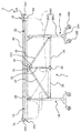
図8は、図2に示すストレッチャーを折り畳んだ状態を説明するための側面図である。
図2および図3に示すように、折り畳み機構3は、ストレッチャー2の左右両側のそれぞれの側に、第1の部分21の後方側の端部と第2の部分22の前方側の端部とを回動可能に連結する2つのセンタージョイント31、31を有している。また、各センタージョイント31には、その鉛直下方に延在するガイドバー32と、ガイドバー32をスライド可能に支持するスライドジョイント33と、ガイドバー32の下端部に設けられたエンドジョイント34とが取り付けられている。
FIG. 8 is a side view for explaining a state in which the stretcher shown in FIG. 2 is folded.
As shown in FIGS. 2 and 3, the folding mechanism 3 includes a rear end portion of the
また、ストレッチャー2の左右両側のエンドジョイント34と、前方側のスライドガイド266の両端部とを、互いに回動可能に連結する前方台35が設けられている。同様に、ストレッチャー2の左右両側のエンドジョイント34と、後方側のスライドガイド266の両端部とを、互いに回動可能に連結する後方台36が設けられている。さらに、ストレッチャー2の左右両側のスライドジョイント33と、前方側のスライドガイド266の両端部とを、互いに回動可能に連結する前方フラットバー37が設けられている。同様に、ストレッチャー2の左右両側のスライドジョイント33と、後方側のスライドガイド266の両端部とを、互いに回動可能に連結する後方フラットバー38が設けられている。
Further, a
スライドジョイント33には、ガイドバー32がスライドジョイント33に対してスライドするのを禁止するスライドピン331が設けられている。図3に示す状態の入浴装置100から、介護用浴槽1および担架シート4を取り外した状態において、スライドピン331を操作し、ガイドバー32のスライド禁止状態を解除すると、ガイドバー32が上方に向かってスライド可能となる。
The slide joint 33 is provided with a
この状態で、ストレッチャー2の第1の部分21の前方連結部24と第2の部分22の後方連結部25とを下側に押圧すると、ガイドバー32がスライドジョイント33に対して上側にスライドして、フレーム20の第1の部分21の前方側の端部および第2の部分22の後方側の端部が、押圧方向(下側)に移動する。そして、押圧を続けることにより、図8に示すように、第1の部分21と第2の部分22とが、前方連結部24と後方連結部25とが互いに近接するように折り畳まれる。
In this state, when the front connecting
このようにして折り畳まれたストレッチャー2は、折り畳まれる前の状態(図2の状態)のストレッチャー2に比べて、極めてコンパクトになる。入浴装置100は、未使用状態においては、ストレッチャー2から、介護用浴槽1および担架シート4を取り外して、図8に示すような折り畳み状態とすることにより、入浴装置100の設置スペースを圧迫することなく、省スペース化を図ることができる。
The stretcher 2 folded in this manner is extremely compact compared to the stretcher 2 in a state before being folded (the state shown in FIG. 2). In the unused state, the
このようなストレッチャー2(フレーム20)に介護用浴槽1を取り付けた状態で、担架シート4の筒状部に挿通された各ロープ41の両端部を前方連結部24のスナップ241と後方連結部25のスナップ59とに固定する。
With the nursing tub 1 attached to such a stretcher 2 (frame 20), the both ends of each
この状態で、ハンドル53を回転させることにより、ロープ41、41の牽引または弛緩させることができる。これにより、担架シート4に入浴者を乗せた状態で、ハンドル53を回転させて、ロープ41、41を弛緩させることにより、担架シート4が介護用浴槽1内に下降して担架シート4に乗せた入浴者を入浴させることができる。
By rotating the
このような入浴装置100では、ストレッチャー2(フレーム20)への介護用浴槽1の着脱が容易である。また、ストレッチャー2の長さおよび幅を、介護用浴槽1のサイズに合わせることができ、十分にそのサイズを抑えることができる。したがって、このような入浴装置100は、従来の入浴装置に比べて、設置スペースを抑えて省スペース化を図ることができる。また、介護用浴槽1と入浴者を乗せて入浴させるための担架シート4とが、ストレッチャー2に一体的に取り付けられるため、利便性も向上させることができる。
In such a
なお、このような入浴装置100は、介護用浴槽1を取り外した状態で、通常のストレッチャーとして使用することも可能である。
In addition, such a
以上、本発明の入浴装置について説明したが、本発明はこれに限定されるものではなく、各構成は、同様の機能を発揮し得る任意のものと置換することができ、あるいは、任意の構成のものを付加することができる。 As mentioned above, although the bathing apparatus of this invention was demonstrated, this invention is not limited to this, Each structure can be substituted by the arbitrary things which can exhibit the same function, or arbitrary structures Can be added.
また、上述した本実施形態の入浴装置100は、ストレッチャー2が折り畳み可能に構成されているが、折り畳まれる構成でなくてもよい。
Moreover, although the
また、上述した本実施形態では、介護用浴槽1として、一体型の浴槽であるものについて説明したが、これに限定されない。入浴装置100に用いられる介護用浴槽としては、例えば、複数に分割可能な分割浴槽や、軟質FRP等のフレキシブルな素材で構成され、折り畳み可能な浴槽を用いることもできる。
Moreover, although this embodiment mentioned above demonstrated what is an integrated bathtub as the nursing bathtub 1, it is not limited to this. As a nursing tub used for the
1…介護用浴槽 10…浴槽本体 11…底部 12…側壁部 13…リム部 131…側方リム部 132…前方リム部 133…後方リム部 134…第1の片部 135…第2の片部 136…切欠き部 2…ストレッチャー 20…フレーム 21…第1の部分 22…第2の部分 23…浴槽受け部 231…湾曲部 232…ケース取付部 233…ローラー 234…ボルト 235…ナット 24…前方連結部 241…スナップ 242…連結リング 243…ロック解除レバー 25…後方連結部 251…取っ手 252…ロック解除レバー 26…脚部 261…ピストンロッド 262…ダンパーフレーム 263…ダンパー機構 264…ベースフレーム 265…キャスター 266…スライドガイド 3…折り畳み機構 31…センタージョイント 32…ガイドバー 33…スライドジョイント 331…スライドピン 34…エンドジョイント 35…前方台 36…後方台 37…前方フラットバー 38…後方フラットバー 4…担架シート 41…ロープ 5…巻上機構 51…ケース 511、512…開口部 52…ハンドル取付部 53…ハンドル 54…回転シャフト 55…スライドナット 56…ワイヤ 57…第1の滑車 58…第2の滑車 59…スナップ 100…入浴装置
DESCRIPTION OF SYMBOLS 1 ...
Claims (7)
前記リム部を介して前記介護用浴槽を着脱自在に支持可能な一対の浴槽受け部を有するフレームを備え、走行可能に構成されたストレッチャーと、
前記介護用浴槽上に配置されるように前記フレームに支持され、入浴者を乗せて入浴させるための担架シートとを有し、
前記リム部は、前記側壁部の前記長手方向両側の前記上端部から前記浴槽本体の外側に延出する第1の片部と、前記第1の片部の前記側壁部と反対側の端部から下側に延出する第2の片部とで構成され、前記リム部の断面形状は、略L字状をなしていることを特徴とする入浴装置。 A bathtub body having a generally rectangular shape in plan view configured to store hot water in a space formed by a bottom part and a side wall part standing from the bottom part, and the bathtub from each upper end part on both sides in the longitudinal direction of the side wall part a rim portion which protrudes outside the main body, and nursing bathtubs with,
A stretcher that includes a frame having a pair of bathtub receiving portions that can removably support the nursing tub through the rim portion;
The supported by the frame so as to be disposed nursing on bath, possess a stretcher sheet for bathing put the bather,
The rim portion includes a first piece extending from the upper end on both sides in the longitudinal direction of the side wall to the outside of the bathtub body, and an end of the first piece opposite to the side wall. And a second piece portion extending downward from the rim portion, and the cross-sectional shape of the rim portion is substantially L-shaped .
前記ストレッチャーは、前記フレームに組み込まれ、前記ロープを巻き上げる巻上機構をさらに備えている請求項1に記載の入浴装置。 The stretcher sheet is supported by the frame via a rope inserted through a cylindrical portion formed on both side edges in the longitudinal direction,
The bathing apparatus according to claim 1, wherein the stretcher further includes a hoisting mechanism that is incorporated in the frame and winds up the rope.
前記担架シートは、その長手方向両側縁に形成された筒状部に挿通されるロープを介して前記前方連結部および前記後方連結部に支持されており、
前記前方連結部および前記後方連結部が、前記一対の浴槽受け部よりも高い位置に設けられることによって、前記担架シートは、前記介護用浴槽よりも高い位置に設けられ、
前記入浴者を前記担架シートに乗せた状態で、前記ロープが前記前方連結部および前記後方連結部から吊り下がることによって、前記担架シートが前記介護用浴槽内に位置する請求項1または2に記載の入浴装置。 The frame further includes a front connecting portion that connects one ends of the pair of bathtub receiving portions, and a rear connecting portion that connects the other ends of the pair of bathtub receiving portions,
The stretcher sheet is supported by the front connecting part and the rear connecting part via a rope inserted through a cylindrical part formed on both side edges of the longitudinal direction,
The front coupling portion and the rear coupling portion, the Rukoto which is positioned higher than the pair of bathtub receiving portion, said stretcher sheet, which is positioned higher than the nursing tub,
The said stretcher sheet is located in the said bathtub for care as the said rope hangs from the said front connection part and the said back connection part in the state which put the said bather on the said stretcher sheet. Bathing equipment.
前記介護用浴槽は、前記ストレッチャーの前記浴槽受け部に支持された状態において、前記前方リム部が前記ストレッチャーの前記前方連結部の下側に位置し、前記後方リム部が前記ストレッチャーの前記後方連結部の下側に位置する請求項3に記載の入浴装置。 The nursing tub includes a front rim portion and a rear rim portion projecting from the upper end portions on both sides in the short side direction of the side wall portion to the outside of the bathtub body ,
In the state where the nursing tub is supported by the bathtub receiving portion of the stretcher, the front rim portion is positioned below the front connecting portion of the stretcher, and the rear rim portion is of the stretcher. The bathing apparatus according to claim 3, wherein the bathing apparatus is located below the rear connecting portion.
前記ストレッチャーは、前記フレームの前記第1の部分と前記第2の部分とが、前記前方連結部と前記後方連結部とが互いに近接するように、折り畳み可能に構成されている請求項3または4に記載の入浴装置。 The frame includes a first part including the front connecting part and a second part including the rear connecting part,
The stretcher, said first portion of said frame and said second portion, so that said front connecting portion and the rear connecting portions are close to each other, foldable Configured claim 3 or 4. The bathing apparatus according to 4 .
Priority Applications (1)
| Application Number | Priority Date | Filing Date | Title |
|---|---|---|---|
| JP2015052678A JP6469486B2 (en) | 2015-03-16 | 2015-03-16 | Bathing equipment |
Applications Claiming Priority (1)
| Application Number | Priority Date | Filing Date | Title |
|---|---|---|---|
| JP2015052678A JP6469486B2 (en) | 2015-03-16 | 2015-03-16 | Bathing equipment |
Publications (2)
| Publication Number | Publication Date |
|---|---|
| JP2016171859A JP2016171859A (en) | 2016-09-29 |
| JP6469486B2 true JP6469486B2 (en) | 2019-02-13 |
Family
ID=57009351
Family Applications (1)
| Application Number | Title | Priority Date | Filing Date |
|---|---|---|---|
| JP2015052678A Active JP6469486B2 (en) | 2015-03-16 | 2015-03-16 | Bathing equipment |
Country Status (1)
| Country | Link |
|---|---|
| JP (1) | JP6469486B2 (en) |
Families Citing this family (2)
| Publication number | Priority date | Publication date | Assignee | Title |
|---|---|---|---|---|
| CN109771149B (en) * | 2017-11-10 | 2020-06-05 | 中山市美年健康科技有限公司 | Medical rescue stretcher convenient to fold |
| JP7473108B2 (en) * | 2018-10-09 | 2024-04-23 | 株式会社デベロ | Nursing bathtubs and bathing equipment |
Family Cites Families (6)
| Publication number | Priority date | Publication date | Assignee | Title |
|---|---|---|---|---|
| JPS5753553Y2 (en) * | 1979-08-28 | 1982-11-19 | ||
| JP2554910Y2 (en) * | 1993-01-16 | 1997-11-19 | 光陽自動車 株式会社 | Bathtub with hammock |
| JP2748969B2 (en) * | 1995-11-30 | 1998-05-13 | パラマウントベッド株式会社 | Emergency responsive cot |
| JPH1147215A (en) * | 1997-07-31 | 1999-02-23 | Toshio Yoneda | Stretcher structure of bathtub-lifting type stretcher bathing apparatus |
| JP3613391B2 (en) * | 2001-04-17 | 2005-01-26 | 株式会社テクノブレーン | Winding device |
| JP5822628B2 (en) * | 2011-10-04 | 2015-11-24 | 株式会社デベロ | Nursing bathtub |
-
2015
- 2015-03-16 JP JP2015052678A patent/JP6469486B2/en active Active
Also Published As
| Publication number | Publication date |
|---|---|
| JP2016171859A (en) | 2016-09-29 |
Similar Documents
| Publication | Publication Date | Title |
|---|---|---|
| TWI450712B (en) | Apparatus for turning over and transferring patient | |
| FI94834B (en) | Hospital Bed | |
| JP6733906B2 (en) | Bathing care device | |
| JPH04504068A (en) | patient transfer device | |
| TWI819199B (en) | How to move a caregiver | |
| JP6469486B2 (en) | Bathing equipment | |
| CN106420224A (en) | Nursing transition stretcher | |
| JPH0759247B2 (en) | Patient transfer and nursing equipment | |
| CN201692208U (en) | Assistant nursing frame for hospital bed | |
| US1903536A (en) | Stretcher | |
| US11033447B1 (en) | Rehabilitation wheelchair | |
| JP6594621B2 (en) | Nursing pillow | |
| CN106955207A (en) | Shifting machine for handicapped person | |
| CN105852900A (en) | Radiation protection device of x-ray chest radiography rack | |
| US20200069117A1 (en) | Drying method for limited mobility individuals | |
| JP3089417B1 (en) | Home care lift | |
| JP3205662U (en) | Nursing equipment with robot | |
| CN205814347U (en) | A kind of radioprotector of x-ray chest radiography frame | |
| JP2020031972A (en) | Bathing apparatus for care | |
| JP7471254B2 (en) | Mobility aids, hammocks for mobility aids | |
| CN211750574U (en) | Wheelchair with transfer function | |
| JP2016054861A (en) | Nursing wheelchair | |
| JP2020058520A (en) | Care bathtub and bath device | |
| JP2022142281A (en) | Assistive device | |
| KR20090119158A (en) | A movable bathtub apparatus |
Legal Events
| Date | Code | Title | Description |
|---|---|---|---|
| A621 | Written request for application examination |
Free format text: JAPANESE INTERMEDIATE CODE: A621 Effective date: 20171116 |
|
| A977 | Report on retrieval |
Free format text: JAPANESE INTERMEDIATE CODE: A971007 Effective date: 20180717 |
|
| A131 | Notification of reasons for refusal |
Free format text: JAPANESE INTERMEDIATE CODE: A131 Effective date: 20180814 |
|
| A521 | Request for written amendment filed |
Free format text: JAPANESE INTERMEDIATE CODE: A523 Effective date: 20181012 |
|
| TRDD | Decision of grant or rejection written | ||
| A01 | Written decision to grant a patent or to grant a registration (utility model) |
Free format text: JAPANESE INTERMEDIATE CODE: A01 Effective date: 20190108 |
|
| A61 | First payment of annual fees (during grant procedure) |
Free format text: JAPANESE INTERMEDIATE CODE: A61 Effective date: 20190116 |
|
| R150 | Certificate of patent or registration of utility model |
Ref document number: 6469486 Country of ref document: JP Free format text: JAPANESE INTERMEDIATE CODE: R150 |
|
| R250 | Receipt of annual fees |
Free format text: JAPANESE INTERMEDIATE CODE: R250 |
|
| R250 | Receipt of annual fees |
Free format text: JAPANESE INTERMEDIATE CODE: R250 |
|
| R250 | Receipt of annual fees |
Free format text: JAPANESE INTERMEDIATE CODE: R250 |