JP6469461B2 - Mounting structure of image display device - Google Patents
Mounting structure of image display device Download PDFInfo
- Publication number
- JP6469461B2 JP6469461B2 JP2015012029A JP2015012029A JP6469461B2 JP 6469461 B2 JP6469461 B2 JP 6469461B2 JP 2015012029 A JP2015012029 A JP 2015012029A JP 2015012029 A JP2015012029 A JP 2015012029A JP 6469461 B2 JP6469461 B2 JP 6469461B2
- Authority
- JP
- Japan
- Prior art keywords
- axis direction
- image display
- display device
- pedestal
- fixing member
- Prior art date
- Legal status (The legal status is an assumption and is not a legal conclusion. Google has not performed a legal analysis and makes no representation as to the accuracy of the status listed.)
- Expired - Fee Related
Links
Images


Description
この発明は、台座に取り付けられる画像表示装置の取付構造に関する。 The present invention relates to an attachment structure for an image display device attached to a pedestal.
画像表示装置は、台座に取り付けられて、正確に位置調整されることが望まれることがある。近年、公共空間における情報表示用途、アミューズメント用途、又は業務用途として、単一の画像表示装置では実現が難しい高解像度の画像を大画面で表示する要望が高まっており、マルチディスプレイ装置が用いられるようになっている。マルチディスプレイ装置では、複数の画像表示装置のそれぞれの表示画面が互いに隣接配置されて大画面が形成されるように複数の画像表示装置のそれぞれが台座に取り付ける。例えば、マルチディスプレイ装置は、マトリクス配置された複数の画像表示装置で構成される。 It may be desirable for the image display device to be mounted on a pedestal and accurately aligned. In recent years, there has been an increasing demand for displaying a high-resolution image on a large screen, which is difficult to realize with a single image display device, for information display use, amusement use, or business use in public spaces, and multi-display devices are used. It has become. In the multi-display device, each of the plurality of image display devices is attached to the pedestal so that the display screens of the plurality of image display devices are arranged adjacent to each other to form a large screen. For example, the multi-display device is composed of a plurality of image display devices arranged in a matrix.
このようなマルチディスプレイ装置では、複数の画像表示装置の表示画面の全体で一つの画像が表示される事が多い。このため、画像の表示品質の低下を防ぐために、複数の画像表示装置の間の隙間や大画面における凹凸を無くすように、台座への取り付け時には個々の画像表示装置を精度良く位置決めする必要がある。画像表示装置を台座へ取り付けるための規格として、VESA(Video Electronics Standards Association)マウント規格が知られているが、この規格に準拠した取付構造を用いた場合、位置調整してビスを締めた後で確認するといった作業を繰り返すことになるので、作業性が悪く、取り付け作業に長時間を要している。 In such a multi-display device, one image is often displayed on the entire display screen of a plurality of image display devices. For this reason, in order to prevent a decrease in image display quality, it is necessary to position each image display device with high accuracy when it is attached to a pedestal so as to eliminate gaps between a plurality of image display devices and unevenness on a large screen. . The VESA (Video Electronics Standards Association) mount standard is known as a standard for mounting the image display device to the pedestal. However, when a mounting structure conforming to this standard is used, the position is adjusted and the screw is tightened. Since work such as confirmation is repeated, workability is poor and installation work takes a long time.
そこで、台座に取り付けられた台座側支持板に雄ネジが形成されたピン部材が支持され、画像表示装置の背面に取り付けられた表示側支持板にピン部材がねじ込まれ、ピン部材を回転させることで画像表示装置の上下方向の位置調整が行われ、ピン部材は台座側支持板に横方向に設けられた長孔内を摺動することで画像表示装置が横方向に変位自在に構成された取付構造が提案されている(例えば、特許文献1参照。)。 Therefore, the pin member on which the male screw is formed is supported on the pedestal side support plate attached to the pedestal, and the pin member is screwed into the display side support plate attached to the back surface of the image display device to rotate the pin member. The position of the image display device is adjusted in the vertical direction, and the pin member slides in a long hole provided in the lateral direction on the pedestal side support plate, so that the image display device can be displaced in the lateral direction. An attachment structure has been proposed (for example, see Patent Document 1).
しかし、特許文献1に記載された従来の画像表示装置の取付構造では、画像表示装置を上下方向に変動させる機構、及び横方向に変位自在にする構成は備えられているが、表示画面に直交する方向の位置調整を行うことができず、複数の表示画面で構成される大画面における凹凸を低減させることができないという問題がある。
However, the conventional image display device mounting structure described in
また、従来の画像表示装置の取付構造では、ピン部材に画像表示装置の重量が負荷されるので、ピン部材と台座側支持板との間の摩擦力が大きくなる。このため、画像表示装置を横方向に微調整することが困難であるという問題もある。このように、従来の画像表示装置の取付構造では、画像表示装置の台座への取付位置を調整することが難しい。 Further, in the conventional image display device mounting structure, since the weight of the image display device is loaded on the pin member, the frictional force between the pin member and the pedestal side support plate is increased. For this reason, there is also a problem that it is difficult to finely adjust the image display device in the horizontal direction. Thus, with the conventional image display device mounting structure, it is difficult to adjust the mounting position of the image display device on the pedestal.
この発明の目的は、画像表示装置の台座への取付位置の調整を容易に行うことができる画像表示装置の取付構造を提供することにある。 An object of the present invention is to provide an image display device mounting structure capable of easily adjusting the mounting position of the image display device on a pedestal.
この発明の画像表示装置の取付構造では、画像表示装置は台座に取り付けられる。画像表示装置の取付構造は、1以上の第1取付部材、1以上の第2取付部材、及び1以上の第3取付部材を備える。第1取付部材は、画像表示装置を台座に取り付けた状態において、互いに直交する3方向であって画像表示装置の表示画面の横軸方向に平行なX軸方向、表示画面の縦軸方向に平行なY軸方向、及び表示画面に直交するZ軸方向のうち、Z軸方向に台座に対する画像表示装置の取付位置を変動させる第1変動機構を有し、他の2方向に台座と画像表示装置との相対位置が変位自在に構成される。第2取付部材は、画像表示装置を台座に取り付けた状態において、X軸方向又はY軸方向の何れかの方向並びにZ軸方向に台座に対する画像表示装置の取付位置を変動させる第2変動機構を有し、3方向のうち他の1方向に台座と画像表示装置との相対位置が変位自在に構成される。第3取付部材は、画像表示装置を台座に取り付けた状態において、X軸方向及びY軸方向のうち第2変動機構によって変動させられない方向を含む少なくとも1方向に台座に対する画像表示装置の取付位置を変動させる第3変動機構を有し、3方向のうち他の全方向に台座と画像表示装置との相対位置が変位自在に構成される。 In the image display device mounting structure according to the present invention, the image display device is mounted on the pedestal. The mounting structure of the image display device includes one or more first mounting members, one or more second mounting members, and one or more third mounting members. The first attachment member is in three directions orthogonal to each other in a state in which the image display device is attached to the pedestal, and is parallel to the X-axis direction parallel to the horizontal axis direction of the display screen of the image display device and to the vertical axis direction of the display screen. The first variation mechanism for varying the mounting position of the image display device with respect to the pedestal in the Z-axis direction out of the Y-axis direction and the Z-axis direction orthogonal to the display screen, and the pedestal and the image display device in the other two directions The relative position is configured to be freely displaceable. The second attachment member includes a second variation mechanism that varies the attachment position of the image display device relative to the pedestal in either the X-axis direction or the Y-axis direction and the Z-axis direction in a state where the image display device is attached to the pedestal. And the relative position of the pedestal and the image display device is configured to be displaceable in the other one of the three directions. The third mounting member is a mounting position of the image display device with respect to the pedestal in at least one direction including a direction that is not changed by the second changing mechanism in the X-axis direction and the Y-axis direction in a state where the image display device is mounted on the pedestal. And a relative position between the pedestal and the image display device is configured to be displaceable in all other directions among the three directions.
この構成では、画像表示装置は少なくとも第1変動機構及び第2変動機構によってZ軸方向に動かされ、他の取付部材が台座と画像表示装置との相対位置がZ軸方向に変位自在であるように構成されることで、Z軸方向に位置調整される。また、画像表示装置は、第2変動機構及び第3変動機構のうち少なくとも一方によってY軸方向に動かされ、他の取付部材の全てが台座と画像表示装置との相対位置がY軸方向に変位自在であるように構成されることで、Y軸方向に位置調整される。さらに、画像表示装置は、第2変動機構又は第3変動機構の何れかによってX軸方向に動かされ、他の取付部材の全てが台座と画像表示装置との相対位置がX軸方向に変位自在であるように構成されることで、X軸方向に位置調整される。このように、互いに異なる3方向の全方向に位置調整することができる。 In this configuration, the image display device is moved in the Z-axis direction by at least the first and second variation mechanisms, and the other mounting members are arranged so that the relative positions of the pedestal and the image display device can be displaced in the Z-axis direction. As a result, the position is adjusted in the Z-axis direction. Further, the image display device is moved in the Y-axis direction by at least one of the second variation mechanism and the third variation mechanism, and all the other mounting members are displaced in the Y-axis direction relative to the pedestal and the image display device. By being configured to be free, the position is adjusted in the Y-axis direction. Further, the image display device is moved in the X-axis direction by either the second variation mechanism or the third variation mechanism, and all the other mounting members are displaceable in the X-axis direction relative to the base and the image display device. As a result, the position is adjusted in the X-axis direction. Thus, the position can be adjusted in all three different directions.
また、3方向の全方向について変動機構を備えるので、Z軸方向の位置調整作業中におけるX軸方向及びY軸方向の位置ずれが抑制され、Y軸方向の位置調整作業中におけるX軸方向及びZ軸方向の位置ずれが抑制され、X軸方向の位置調整作業中におけるY軸方向及びZ軸方向の位置ずれが抑制される。 In addition, since the variation mechanism is provided for all three directions, positional deviation in the X-axis direction and the Y-axis direction during the position adjustment work in the Z-axis direction is suppressed, and the X-axis direction and the position in the Y-axis direction during the position adjustment work Misalignment in the Z-axis direction is suppressed, and misalignment in the Y-axis direction and Z-axis direction during position adjustment work in the X-axis direction is suppressed.
さらに、画像表示装置の重量が大きい場合でも、変動機構によって画像表示装置の台座への取付位置を容易に微調整できる。 Furthermore, even when the weight of the image display device is large, the attachment position of the image display device to the pedestal can be easily finely adjusted by the changing mechanism.
また、第1〜第3取付部材の画像表示装置における取付位置及び第1〜第3取付部材の組み合わせによって、X軸方向、Y軸方向、及びZ軸方向に加えて、X軸方向を中心とする回転方向、Y軸方向を中心とする回転方向、及びZ軸方向を中心とする回転方向の、6自由度の位置調整が可能となる。 In addition to the X-axis direction, the Y-axis direction, and the Z-axis direction, depending on the combination of the mounting positions of the first to third mounting members in the image display device and the first to third mounting members, the X-axis direction is the center. It is possible to adjust the position with six degrees of freedom in the rotation direction, the rotation direction about the Y-axis direction, and the rotation direction about the Z-axis direction.
この発明によれば、画像表示装置の台座への取付位置の調整を容易に行うことができる。 According to the present invention, it is possible to easily adjust the mounting position of the image display device on the pedestal.
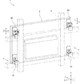
図1に示すように、この発明の第1実施形態に係る画像表示装置の取付構造1は、1以上の第1取付部材10、1以上の第2取付部材20、及び1以上の第3取付部材30を備える。取付構造1によって、画像表示装置2が台座3に取り付けられる。ここで、互いに直交する3方向であるX軸方向、Y軸方向、及びZ軸方向を、画像表示装置2の表示画面の横軸方向に平行な方向をX軸方向、表示画面の縦軸方向に平行な方向をY軸方向、及び表示画面に直交する方向をZ軸方向とする。
As shown in FIG. 1, the image display
一例として、台座3は、X軸方向及びY軸方向に交差するフレーム構造に形成されている。また、一例として、取付構造1は、2個の第1取付部材10、1個の第2取付部材20、及び1個の第3取付部材30を備えている。第1取付部材10は、画像表示装置2の背面の下側の両端部の角部に取り付けられる。第2取付部材20は、画像表示装置2の上側の一方の端部の角部に取り付けられ、第3取付部材30は、画像表示装置2の上側の他方の端部の角部に取り付けられる。
As an example, the
画像表示装置2の取付構造1は、1個の画像表示装置2の台座3への取付位置の調整を行うために用いることができるが、複数の画像表示装置2が互いに隣接配置されてマルチディスプレイ装置を構成する場合により高い有効性が奏される。一例として、複数の画像表示装置2が、マトリクス配置される場合を想定する。
The
図2(A)及び図2(B)に示すように、第1取付部材10は、第1台座固定部材11、第1装置固定部材12、第1連結部材13、及び第1調整ボルト14を含む。第1台座固定部材11は、溶接やネジ留め等によって台座3に固定される。第1装置固定部材12は、ネジ留め等によって画像表示装置2に固定される。第1連結部材13は、第1台座固定部材11と第1装置固定部材12とを、以下のようにして連結する。
As shown in FIGS. 2A and 2B, the first mounting
第1台座固定部材11は、雌ネジが形成された孔部111,112を有している。
The 1st
第1装置固定部材12は、Z軸方向に第1調整ボルト14がねじ込まれる第1ネジ孔121を有している。
The first
第1連結部材13は、X−Z面及びX−Y面を有するL字形の板部材で形成され、X−Z面にX軸方向に長い長孔131,132を有し、X−Y面にY軸方向に上方から直線状に切り込まれたスリット133を有している。Y軸方向に長孔131,132を通して孔部111,112にビスがねじ込まれることで、第1台座固定部材11と第1連結部材13とを、X軸方向に互いに異なる複数の相対位置に配置された状態で連結することができる。
The first connecting
第1調整ボルト14は、第1係止部141を有している。一例として、第1係止部141は、2枚の円板によってX−Y面に平行に挿入自在な溝状に形成されている。第1係止部141に第1連結部材13が嵌まるように第1調整ボルト14をスリット133に挿入することで、第1調整ボルト14は、第1連結部材13に対するZ軸方向の移動を規制されかつY軸方向に変位自在に第1係止部141を第1連結部材13に係止される。
The
第1係止部141が第1連結部材13に係止された状態で、第1装置固定部材12の第1ネジ孔121に対する第1調整ボルト14のねじ込み量を調整することで、第1装置固定部材12と第1台座固定部材11とのZ軸方向の相対位置が調整される。
The first device is adjusted by adjusting the screwing amount of the
このように、第1取付部材10は、画像表示装置2が台座3に取り付けられた状態において、Z軸方向に台座3に対する画像表示装置2の取付位置を変動させる第1変動機構を有し、かつX軸方向及びY軸方向に台座3と画像表示装置2との相対位置が変位自在に構成されている。第1係止部141、スリット133、及び第1装置固定部材12の第1ネジ孔121は、第1変動機構に含まれる。
Thus, the
図3(A)及び図3(B)に示すように、第2取付部材20は、第2台座固定部材21、第2装置固定部材22、第2連結部材23、第2調整ボルト24、第3調整ボルト25、及び脱落防止部材26を含む。
As shown in FIGS. 3A and 3B, the second mounting
第2台座固定部材21は、台座3に固定される。第2装置固定部材22は、画像表示装置2に固定される。第2連結部材23は、第2台座固定部材21と第2装置固定部材22とを以下のようにして連結する。
The second
第2装置固定部材22は、Z軸方向に第2調整ボルト24がねじ込まれる第2ネジ孔221を有している。
The second
第2台座固定部材21は、Y軸方向に第3調整ボルト25がねじ込まれる第3ネジ孔211を有している。
The second
第2連結部材23は、少なくともX−Z面及びX−Y面を有している。第2連結部材23は、X−Z面にZ軸方向に直線状に切り込まれたスリット231を有している。第2連結部材23は、X−Y面に、上方からY軸方向に切り込まれ、この切り込みの下端部でX軸方向に長い長孔状に形成された切り込み部232を有している。即ち、切り込み部232は、逆T字形に形成されている。
The second connecting
第2調整ボルト24は、第2係止部241を有している。第3調整ボルト25は、第3係止部251を有している。第2調整ボルト24及び第3調整ボルト25は、第1調整ボルト14と実質的に同様に構成されている。
The
第2係止部241に第2連結部材23が嵌まるように第2調整ボルト24を切り込み部232に挿入することで、第2調整ボルト24は、第2連結部材23に対するZ軸方向の移動を規制され、かつX軸方向に変位自在に第2係止部241を第2連結部材23に係止される。なお、第2調整ボルト24は、画像表示装置2の重量によって切り込み部232の下端部に配置される。
The
第3係止部251に第2連結部材23が嵌まるように第3調整ボルト25をスリット231に挿入した後、第3調整ボルト25がスリット231からZ軸方向に抜けないように脱落防止部材26を第2連結部材にネジ留め等によって取り付けることで、第3調整ボルト25は、第2連結部材23に対するX軸方向、Y軸方向及びZ軸方向の3方向の移動を規制されるように第3係止部251を第2連結部材23に係止される。
After the
第2係止部241が第2連結部材23に係止された状態で、第2装置固定部材22の第2ネジ孔221に対する第2調整ボルト24のねじ込み量を調整することで、第2装置固定部材22と第2台座固定部材21とのZ軸方向の相対位置が調整される。
By adjusting the screwing amount of the
同様に、第3係止部251が第2連結部材23に係止された状態で、第2台座固定部材21の第3ネジ孔211に対する第3調整ボルト25のねじ込み量を調整することで、第2装置固定部材22と第2台座固定部材21とのY軸方向の相対位置が調整される。
Similarly, by adjusting the screwing amount of the
このように、第2取付部材20は、画像表示装置2が台座3に取り付けられた状態において、Z軸方向及びY軸方向に台座3に対する画像表示装置2の取付位置を変動させる第2変動機構を有し、かつX軸方向に台座3と画像表示装置2との相対位置が変位自在に構成されている。第2係止部241、第3係止部251、スリット231、切り込み部232、及び第2装置固定部材22の第2ネジ孔221、第2台座固定部材21の第3ネジ孔211は、第2変動機構に含まれる。
As described above, the
図4(A)及び図4(B)に示すように、第3取付部材30は、画像表示装置2が台座3に取り付けられた状態において、X軸方向及びY軸方向のうち第2変動機構によって変動させられない方向を含み3方向のうちの少なくとも1方向に台座3に対する画像表示装置2の取付位置を変動させる第3変動機構を有し、かつ3方向のうち他の全方向に台座3と画像表示装置2との相対位置が変位自在に構成される。この第1実施形態では、第2変動機構は画像表示装置2をZ軸方向及びY軸方向に変動させるので、第3変動機構は、少なくともX軸方向を含む方向であって3方向のうちの少なくとも1方向に画像表示装置2を変動させることになる。この第1実施形態では、第3変動機構は、X軸方向、Y軸方向、及びZ軸方向に画像表示装置2を変動させるように構成される。より具体的には、第3取付部材30は、つぎのように構成される。
As shown in FIGS. 4A and 4B, the
第3取付部材30は、第3台座固定部材31、第3装置固定部材32、第3連結部材33、第4調整ボルト34、第5調整ボルト35、第6調整ボルト36、及び脱落防止部材37を含む。
The third mounting
第3台座固定部材31は、台座3に固定される。第3装置固定部材32は、画像表示装置2に固定される。第3連結部材33は、第3台座固定部材31と第3装置固定部材32とを以下のようにして連結する。
The third
第3装置固定部材32は、X−Y面及びY−Z面を有し、X−Y面にZ軸方向に第4調整ボルト34がねじ込まれる第4ネジ孔321を有し、Y−Z面にX軸方向に第5調整ボルト35がねじ込まれる第5ネジ孔322を有している。
The third
第3台座固定部材31は、X−Z面を有し、X−Z面にY軸方向に第6調整ボルト36がねじ込まれる第6ネジ孔311を有している。
The third
第3連結部材33は、X−Z面、X−Y面、及びY−Z面を有している。第3連結部材33は、X−Z面にスリット231と同様のスリット331を有し、X−Y面に切り込み部232と同様の切り込み部332を有し、Y−Z面に切り込み部333を有している。切り込み部333は、上方からY軸方向に切り込まれ、この切り込みの下端部でZ軸方向に長い長孔状に形成されている。
The third connecting
第4調整ボルト34は、第4係止部341を有している。第5調整ボルト35は、第5係止部351を有している。第6調整ボルト36は、第6係止部361を有している。第4調整ボルト34、第5調整ボルト35、及び第6調整ボルト36は、第1調整ボルト14と実質的に同様に構成されている。
The
第4係止部341に第3連結部材33が嵌まるように第4調整ボルト34を切り込み部332に挿入することで、第4調整ボルト34は、第3連結部材33に対するZ軸方向の移動を規制され、かつX軸方向に変位自在に第4係止部341を第3連結部材33に係止される。なお、第4調整ボルト34は、画像表示装置2の重量によって切り込み部332の下端部に配置される。
The
第5係止部351に第3連結部材33が嵌まるように第5調整ボルト35を切り込み部333に挿入することで、第5調整ボルト35は、第3連結部材33に対するX軸方向の移動を規制され、かつZ軸方向に変位自在に第5係止部351を第3連結部材33に係止される。なお、第5調整ボルト35は、画像表示装置2の重量によって切り込み部333の下端部に配置される。
The
第6係止部361に第3連結部材33が嵌まるように第6調整ボルト36をスリット331に挿入した後、第6調整ボルト36がスリット331からZ軸方向に抜けないように脱落防止部材37を第3連結部材33にネジ留め等によって取り付けることで、第6調整ボルト36は、第3連結部材33に対するX軸方向、Y軸方向及びZ軸方向の3方向の移動を規制されるように第6係止部361を第3連結部材33に係止される。
After the
第4係止部341が第3連結部材33に係止された状態で、第3装置固定部材32の第4ネジ孔321に対する第4調整ボルト34のねじ込み量を調整することで、第3装置固定部材32と第3台座固定部材31とのZ軸方向の相対位置が調整される。
The third device is adjusted by adjusting the screwing amount of the
第5係止部351が第3連結部材33に係止された状態で、第3装置固定部材32の第5ネジ孔322に対する第5調整ボルト35のねじ込み量を調整することで、第3装置固定部材32と第3台座固定部材31とのX軸方向の相対位置が調整される。
The third device is adjusted by adjusting the screwing amount of the
第6係止部361が第3連結部材33に係止された状態で、第3台座固定部材31の第6ネジ孔311に対する第6調整ボルト36のねじ込み量を調整することで、第3装置固定部材32と第3台座固定部材31とのY軸方向の相対位置が調整される。
By adjusting the screwing amount of the
このように、第3取付部材30は、画像表示装置2が台座3に取り付けられた状態において、X軸方向、Y軸方向、及びZ軸方向の3方向の全方向に台座3に対する画像表示装置2の取付位置を変動させる第3変動機構を有している。第4係止部341、第5係止部351、第6係止部361、スリット331、切り込み部332,333、第2装置固定部材32の第4ネジ孔321、第5ネジ孔322、第3台座固定部材31の第6ネジ孔311は、第3変動機構に含まれる。
Thus, the
つぎに、台座3に対する画像表示装置2の取付位置の調整方法について説明する。
Next, a method for adjusting the mounting position of the
2個の第1取付部材10、第2取付部材20及び第3取付部材30の連結部材13,23,33をそれぞれ対応する台座固定部材11,21,31に、調整ボルト25,36を有効ネジ長さの半分程度までねじ込んだ状態で取り付ける。
The connecting
調整ボルト14,24,34,35をそれぞれ有効ネジ長さの半分程度までねじ込んだ状態で、第1調整ボルト14をスリット部133に、第2調整ボルト24を切り込み部232に、第4調整ボルト34を切り込み部332に、第5調整ボルト35を切り込み部333に嵌めることで、画像表示装置2を台座3に取り付ける。
With the
画像表示装置2の台座3への取付位置をX軸方向に調整する場合、第3取付部材30の第5調整ボルト35を回転させる。これによって、画像表示装置2は、X軸方向に平行に変動する。
When the attachment position of the
画像表示装置2の台座3への取付位置をY軸方向に調整する場合、第2取付部材20の第3調整ボルト25及び第3取付部材30の第6調整ボルト36を、互いに同方向に回転させる。これによって、画像表示装置2は、Y軸方向に平行に変動する。
When adjusting the mounting position of the
画像表示装置2の台座3への取付位置をZ軸方向に調整する場合、2個の第1取付部材10のそれぞれの第1調整ボルト14、第2取付部材20の第2調整ボルト24、及び第3取付部材30の第4調整ボルト34を、互いに同方向に回転させる。これによって、画像表示装置2は、Z軸方向に平行に変動する。
When adjusting the mounting position of the
また、第1調整ボルト14,14、第2調整ボルト24、及び第4調整ボルト34を個別に必要量ずつ回転させることで、隣接する画像表示装置2同士の表示画面の凹凸を低減させることができる。これによって、複数の画像表示装置2の表示画面で構成される大画面における凹凸を低減させることができる。
Moreover, the unevenness | corrugation of the display screen of adjacent
さらに、第1調整ボルト14,14、第2調整ボルト24、及び第4調整ボルト34の回転方向の組み合わせ次第で、画像表示装置2を、X軸方向を中心とする回転方向、Y軸方向を中心とする回転方向に回転させることもできる。
Furthermore, depending on the combination of the rotation directions of the
また、第2取付部材20の第3調整ボルト25と第3取付部材30の第6調整ボルト36とを、互いに反対方向に回転させることで、画像表示装置2をZ軸方向を中心とする回転方向に回転させることもできる。
Further, by rotating the
このように、取付構造1によれば、画像表示装置2の台座3への取付位置について、X軸方向、Y軸方向、及びZ軸方向に加えて、X軸方向を中心とする回転方向、Y軸方向を中心とする回転方向、及びZ軸方向を中心とする回転方向の、6自由度の位置調整を行うことができる。
As described above, according to the mounting
また、画像表示装置2の重量が大きい場合でも、作業者が調整ボルト14,24,25,34,35,36を回転させることで、回転量に応じて画像表示装置2の台座3への取付位置が変動するので、画像表示装置2の台座3への取付位置を容易に微調整することができる。
Even when the weight of the
さらに、3方向の全方向について変動機構を備えるので、Z軸方向の位置調整作業中におけるX軸方向及びY軸方向の位置ずれが抑制され、Y軸方向の位置調整作業中におけるX軸方向及びZ軸方向の位置ずれが抑制され、X軸方向の位置調整作業中におけるY軸方向及びZ軸方向の位置ずれが抑制される。 Furthermore, since the variable mechanism is provided for all three directions, positional deviations in the X-axis direction and the Y-axis direction during position adjustment work in the Z-axis direction are suppressed, and the X-axis direction during position adjustment work in the Y-axis direction and Misalignment in the Z-axis direction is suppressed, and misalignment in the Y-axis direction and Z-axis direction during position adjustment work in the X-axis direction is suppressed.
したがって、画像表示装置2の台座3への取付位置の調整を容易に行うことができる。
Therefore, it is possible to easily adjust the mounting position of the
図5に示すように、第2実施形態に係る画像表示装置2の取付構造1Aは、1個の第1取付部材70、1個の第2取付部材80、及び2個の第3取付部材90を備えている。第1取付部材70は、画像表示装置2の背面の下側のX軸方向における一方の角部に取り付けられ、第2取付部材80は、画像表示装置2の下側の他方の角部に取り付けられる。第3取付部材90は、画像表示装置2の上側のX軸方向における両端部の角部に取り付けられる。
As shown in FIG. 5, the mounting
第2取付部材80は、画像表示装置2が台座3に取り付けられた状態において、Z軸方向及びX軸方向に台座3に対する画像表示装置2の取付位置を変動させる変動機構を有し、かつY軸方向に台座3と画像表示装置2との相対位置が変位自在であるように構成される。
The
図6(A)及び図6(B)に示すように、第2取付部材80は、第2台座固定部材81、第2装置固定部材82、第2連結部材83、第2調整ボルト84、第3調整ボルト85、及び脱落防止部材86を含む。
As shown in FIGS. 6A and 6B, the second mounting
第2台座固定部材81は、少なくともY−Z面を有し、溶接やネジ留め等によって台座3に固定され、X軸方向に第3調整ボルト25がねじ込まれる第3ネジ孔811をY−Z面に有する。
The second
第2連結部材83は、X−Y面及びY−Z面を有する。第2連結部材83は、Y−Z面に、Z軸方向に背面側から正面側へ直線状に切り込まれたスリット831を有している。
The second connecting
第3調整ボルト85は、第3係止部851を有している。第3調整ボルト85は、第1調整ボルト14と実質的に同様に構成されている。第3係止部851に第2連結部材83が嵌まるように第3調整ボルト85をY−Z面のスリット831に挿入した後、第3調整ボルト85がスリット831からZ軸方向に抜けないように脱落防止部材86を第2連結部材83にネジ留め等によって取り付けることで、第3調整ボルト85は、第2連結部材83に対するX軸方向、Y軸方向及びZ軸方向の3方向の移動を規制されるように第3係止部851を第2連結部材83に係止される。
The
第3調整ボルト85を回転させることで、画像表示装置2が台座3に対してX軸方向に変動する。
By rotating the
第2連結部材83は、X−Y面に、Y軸方向に上方から直線状に切り込まれたスリット832を有している。スリット832は、第1連結部材13のスリット133と実質的に同様に構成されている。
The second connecting
第2調整ボルト84は、第2係止部841を有している。第2調整ボルト84は、第1調整ボルト14と実質的に同様に構成されている。第2係止部841が第2連結部材83に係止された状態で、第2装置固定部材82の第2ネジ孔821に対する第2調整ボルト84のねじ込み量を調整することで、第2装置固定部材82と第2台座固定部材81とのZ軸方向の相対位置が調整される。
The
このように、第2取付部材80は、画像表示装置2が台座3に取り付けられた状態においてZ軸方向及びX軸方向に台座3に対する画像表示装置2の取付位置を変動させる変動機構を有し、かつY軸方向に台座3と画像表示装置2との相対位置が変位自在に構成されている。
As described above, the
この第2実施形態に係る取付構造1Aでは、第1取付部材70は、Z軸方向に台座3に対する画像表示装置2の取付位置を変動させる変動機構を有することが好ましい。即ち、第1取付部材70は、図2(A)及び図2(B)に示す第1実施形態における第1取付部材10と実質的に同様に構成されることが好ましい。また、第3取付部材90は、Y軸方向及びZ軸方向に台座3に対する画像表示装置2の取付位置を変動させる変動機構を有することが好ましい。即ち、第3取付部材90は、図3(A)及び図3(B)に示す第1実施形態における第2取付部材20と実質的に同様に構成されることが好ましい。
In the mounting structure 1A according to the second embodiment, it is preferable that the first mounting
取付構造1Aによっても、画像表示装置2の台座3への取付位置の調整を容易に行うことができる。
The mounting position of the
図7に示すように、第3実施形態に係る画像表示装置2の取付構造1Bは、2個の第1取付部材40、2個の第2取付部材50、及び1個の第3取付部材60を備えている。第1取付部材40は、画像表示装置2の背面の下側の両端部の角部に取り付けられる。第2取付部材50は、画像表示装置2の上側の両端部の角部に取り付ける。第3取付部材60は、画像表示装置2の上端部のX軸方向における中央部に取り付けられる。
As shown in FIG. 7, the mounting
図8及び図9に示すように、第1取付部材40は、台座固定部材41、装置固定部材42、調整シャフト43、調整板44、及びシャフト取付板451,452を含む。
As shown in FIGS. 8 and 9, the first mounting
調整シャフト43は、Y軸方向に配置され、シャフト部431、円板部432、及び突起部433を有している。円板部432は、シャフト部431の下端に、シャフト部431と同心に設けられている。突起部433は、円板部432のシャフト部431とは反対側の面に、シャフト部431とは異なる中心軸を有するように設けられている。
The
調整シャフト43は、シャフト部431の下端部に、ナット形状をなす操作部434をさらに有している。操作部434は、円板部432との間に間隙が設けられる位置において、シャフト部431に固定されている。
The
台座固定部材41は、台座3に固定されている。台座固定部材41は、X−Z面に、孔部411を有している。孔部411は、X軸方向に長い長孔である。
The
調整板44は、Z軸方向に長いZ軸長孔441を有している。Z軸長孔441は、孔部411よりも大きい。調整板44は、Z軸長孔441を通して孔部411を露出させるように台座固定部材41のX−Z面に固定されている。
The
調整シャフト43は、突起部433が孔部411に挿入され、円板部432がZ軸長孔441内をZ軸方向に摺動自在にZ軸長孔441に嵌まるように配置されている。
The
シャフト取付板451,452は、シャフト部431を挟み付けるようにして円板部432と操作部434との間隙に挿入され、円板部432の上に被さるようにして調整板44に取り付けられる。これによって、シャフト部431が台座固定部材41に取り付けられる。シャフト取付板451,452が調整板44に取り付けられた状態において、シャフト取付板451とシャフト板452との間には、調整シャフト43をZ軸方向に移動自在にするZ軸方向に長い長孔が形成される。
The
装置固定部材42は、画像表示装置2に固定されている。装置固定部材42は、X−Z面に、X軸方向に長いX軸長孔421を有している。X軸長孔421には、シャフト部431が挿入される。X軸長孔421は、シャフト部431のZ軸方向の移動を規制する。シャフト部431は、X軸長孔421内をX軸方向及びY軸方向に変位自在である。
The
第1取付部材40では、作業者が操作部434を操作して調整シャフト43を回転させると、調整シャフト43は突起部433を支点にして円板部432が回転し、シャフト部431がZ軸長孔441に沿ってZ軸方向に移動する。このように、第1取付部材40では、クランク方式によってシャフト部431がZ軸方向に移動する。
In the first mounting
シャフト部431がZ軸方向に移動すると、装置固定部材42もシャフト部431とともにZ軸方向に移動し、画像表示装置2も台座3に対してZ軸方向に移動する。
When the
このように、第1取付部材40では、作業者による操作部434の回転量に応じて、画像表示装置2を台座3に対してZ軸方向に移動させることができる。
Thus, in the
図10及び図11に示すように、第2取付部材50は、支持ナット435をさらに備え、シャフト部431に雄ネジが形成され、シャフト部431に支持ナット435が嵌められている点を除いて、第1取付部材40と同様に構成されている。説明の便宜上、第1取付部材40と同様の構成については同じ符号を使用する。
As shown in FIGS. 10 and 11, the second mounting
支持ナット435は、シャフト部431に嵌められ、作業者が支持ナット435を回転させることで、支持ナット435はシャフト部431に沿ってY軸方向に移動する。
The
装置固定部材42は、X軸長孔421にシャフト部431が挿入されるように配置され、支持ナット435によってY軸方向に支持される。
The
作業者が支持ナット435を回転させることで、支持ナット435がY軸方向に移動し、これにともなって装置固定部材42も台座3に対してY軸方向に移動する。
When the operator rotates the
第2取付部材50では、画像表示装置2を台座3に対してZ軸方向に移動させるための機構にクランク方式が採用されており、画像表示装置2を台座3に対してZ軸方向に変動させるために操作部434を回転させる面と、画像表示装置2を台座3に対してY軸方向に変動させるために支持ナット435を回転させる面とが平行であり、作業者の第2取付部材50に対するアプローチの方向が同じなる。このため、画像表示装置2の台座3に対する取付位置の調整のために必要な作業スペースが小さくて済む。よって、画像表示装置2及び台座3の設置場所の自由度が向上する。
The second mounting
図12及び図13に示すように、第3取付部材60は、画像表示装置2を台座3に対してZ軸方向ではなくX軸方向に変動させるように構成される点を除いて、第1取付部材40と同様に構成されている。説明の便宜上、第1取付部材40と同様の構成については同じ符号を使用する。
As shown in FIGS. 12 and 13, the third mounting
第3取付部材60では、台座固定部材61の孔部611は、Z軸方向に長い長孔である。調整板64は、Z軸長孔441に代えて、X軸方向に長いX軸長孔641を有している。X軸長孔641は、孔部611よりも大きい。
In the third mounting
調整シャフト43は、突起部433が孔部611に挿入され、円板部432がX軸長孔641内をX軸方向に摺動自在にX軸長孔641に嵌まるように配置されている。
The
シャフト取付板451,452は、シャフト取付板451とシャフト板452との間に、調整シャフト43をX軸方向に移動自在にするX軸方向に長い長孔が形成されるように、調整板64に取り付けられる。
The
装置固定部材62は、X−Z面に、X軸長孔421に代えて、Z軸方向に長いZ軸長孔621を有している。Z軸長孔621は、シャフト部431のX軸方向の移動を規制する。シャフト部431は、Z軸長孔621内をZ軸方向及びY軸方向に変位自在である。
The
第3取付部材60では、作業者が操作部434を操作して調整シャフト43を回転させると、調整シャフト43は突起部433を支点にして円板部432が回転し、シャフト部431がX軸長孔641に沿ってX軸方向に移動する。シャフト部431がX軸方向に移動すると、装置固定部材42もシャフト部431とともにX軸方向に移動し、画像表示装置2も台座3に対してX軸方向に移動する。
In the
第3実施形態に係る画像表示装置2の取付構造1Bでは、画像表示装置2の台座3への取付位置をX軸方向に調整する場合、作業者は第3取付部材60の操作部434を回転させる。これによって、画像表示装置2は、X軸方向に平行に変動する。
In the mounting
画像表示装置2の台座3への取付位置をY軸方向に調整する場合、2個の第2取付部材50の支持ナット435を互いに同方向に回転させる。これによって、画像表示装置2は、Y軸方向に平行に変動する。
When adjusting the mounting position of the
画像表示装置2の台座3への取付位置をZ軸方向に調整する場合、2個の第1取付部材40のそれぞれの操作部434、及び2個の第2取付部材50のそれぞれの操作部434を、互いに同方向に回転させる。これによって、画像表示装置2は、Z軸方向に平行に変動する。
When adjusting the mounting position of the
また、2個の第1取付部材40のそれぞれの操作部434及び2個の第2取付部材50のそれぞれの操作部434を個別に必要量ずつ回転させることで、隣接する画像表示装置2同士の表示画面の凹凸を低減させることができる。これによって、複数の画像表示装置2の表示画面で構成される大画面における凹凸を低減させることができる。
In addition, by rotating the
さらに、画像表示装置2の一方の側端部の第1取付部材40の操作部434と第2取付部材50の操作部434とを1組とし、他方の側端部の第1取付部材40の操作部434と第2取付部材50の操作部434とを1組とし、同じ組の操作部434同士は互いに同方向に回転させ、異なる組の操作部434とは反対方向に回転させることで、画像表示装置2をY軸方向を中心として回転させることができる。
Further, the operating
同様に、2個の第1取付部材40の操作部434を1組とし、2個の第2取付部材50の操作部434を1組とし、同じ組の操作部434同士は互いに同方向に回転させ、異なる組の操作部434とは反対方向に回転させることで、画像表示装置2をX軸方向を中心として回転させることができる。
Similarly, the
また、一方の第2取付部材50の支持ナット435と他方の第2取付部材50の支持ナット435とを互いに反対方向に回転させることで、画像表示装置2をZ軸方向を中心として回転させることができる。
Further, the
このように、取付構造1Bによっても、画像表示装置2の台座3への取付位置について、X軸方向、Y軸方向、及びZ軸方向に加えて、X軸方向を中心とする回転方向、Y軸方向を中心とする回転方向、及びZ軸方向を中心とする回転方向の、6自由度の位置調整を行うことができる。
As described above, even with the mounting
また、画像表示装置2の重量が大きい場合でも、取付部材40,50,60の各操作部434及び支持ナット435を回転させることで、画像表示装置2の台座3への取付位置を容易に微調整することができる。
Even when the weight of the
さらに、3方向の全方向について変動機構を備えるので、Z軸方向の位置調整作業中におけるX軸方向及びY軸方向の位置ずれが抑制され、Y軸方向の位置調整作業中におけるX軸方向及びZ軸方向の位置ずれが抑制され、X軸方向の位置調整作業中におけるY軸方向及びZ軸方向の位置ずれが抑制される。 Furthermore, since the variable mechanism is provided for all three directions, positional deviations in the X-axis direction and the Y-axis direction during position adjustment work in the Z-axis direction are suppressed, and the X-axis direction during position adjustment work in the Y-axis direction and Misalignment in the Z-axis direction is suppressed, and misalignment in the Y-axis direction and Z-axis direction during position adjustment work in the X-axis direction is suppressed.
したがって、画像表示装置2の台座3への取付位置の調整を容易に行うことができる。
Therefore, it is possible to easily adjust the mounting position of the
なお、第3取付部材60は、画像表示装置2の下端部のX軸方向における中央部に取り付けることもできる。
The
また、取付部材10,20,30、取付部材70,80,90、及び取付部材40,50,60の画像表示装置2の背面における取付位置及び取付個数は、上記各実施形態に記載された箇所及び個数に限定されない。
Further, the mounting positions and the number of mounting
さらに、取付部材10,20,30のうちの何れかを、取付部材40,50,60の中で同機能を有するもので代替して使用することができる。同様に、取付部材40,50,60のうちの何れかを、取付部材10,20,30の中で同機能を有するもので代替して使用することもできる。
Furthermore, any of the
同様に、取付部材70,80,90のうちの何れかを、取付部材40,50,60の中で同機能を有するもので代替して使用することができ、取付部材40,50,60のうちの何れかを、取付部材70,80,90の中で同機能を有するもので代替して使用することもできる。
Similarly, any of the
上述の実施形態のそれぞれの技術的特徴を互いに組み合わせることで、新たな実施形態を構成することが考えられる。 It is conceivable to construct a new embodiment by combining the technical features of the above-described embodiments.
上述の実施形態の説明は、すべての点で例示であって、制限的なものではないと考えられるべきである。本発明の範囲は、上述の実施形態ではなく、特許請求の範囲によって示される。さらに、本発明の範囲には、特許請求の範囲と均等の意味および範囲内でのすべての変更が含まれることが意図される。 The above description of the embodiment is to be considered in all respects as illustrative and not restrictive. The scope of the present invention is shown not by the above embodiments but by the claims. Furthermore, the scope of the present invention is intended to include all modifications within the meaning and scope equivalent to the scope of the claims.
1,1A,1B…取付構造
2…画像表示装置
3…台座
10,40,70…第1取付部材
20,50,80…第2取付部材
30,60,90…第3取付部材
11…第1第座固定部材
12…第1装置固定部材
13…第1連結部材
14…第1調整ボルト
21,81…第2台座固定部材
22,82…第2装置固定部材
23,83…第2連結部材
24,84…第2調整ボルト
25,85…第3調整ボルト
31…第3台座固定部材
32…第3装置固定部材
33…第3連結部材
34…第4調整ボルト
35…第5調整ボルト
36…第6調整ボルト
41,61…台座固定部材
42,62…装置固定部材
43…調整シャフト
DESCRIPTION OF
Claims (10)
前記画像表示装置を前記台座に取り付けた状態において、互いに直交する3方向であって前記画像表示装置の表示画面の横軸方向に平行なX軸方向、前記表示画面の縦軸方向に平行なY軸方向、及び前記表示画面に直交するZ軸方向のうち、前記Z軸方向に前記台座に対する前記画像表示装置の取付位置を変動させる第1変動機構を有し、他の2方向に前記台座と前記画像表示装置との相対位置が変位自在に構成される1以上の第1取付部材と、
前記画像表示装置を前記台座に取り付けた状態において、前記X軸方向又は前記Y軸方向の何れかの方向並びに前記Z軸方向に前記台座に対する前記画像表示装置の取付位置を変動させる第2変動機構を有し、前記3方向のうち他の1方向に前記台座と前記画像表示装置との相対位置が変位自在に構成される1以上の第2取付部材と、
前記画像表示装置を前記台座に取り付けた状態において、前記X軸方向及び前記Y軸方向のうち前記第2変動機構によって変動させられない方向並びに前記Z軸方向を含む少なくとも2方向に前記台座に対する前記画像表示装置の取付位置を変動させる第3変動機構を有し、前記3方向のうち他の全方向に前記台座と前記画像表示装置との相対位置が変位自在に構成される1以上の第3取付部材とを備える、画像表示装置の取付構造。 An image display device mounting structure for mounting an image display device to a pedestal,
In the state where the image display device is attached to the pedestal, the X direction is parallel to the horizontal axis direction of the display screen of the image display device, and the Y direction is parallel to the vertical direction of the display screen. Of the axial direction and the Z-axis direction orthogonal to the display screen, the first variation mechanism varies the attachment position of the image display device with respect to the pedestal in the Z-axis direction, and the pedestal in the other two directions. One or more first mounting members configured to be displaceable relative to the image display device;
In a state where the image display device is attached to the pedestal, a second variation mechanism that varies the attachment position of the image display device with respect to the pedestal in either the X-axis direction or the Y-axis direction and the Z-axis direction. One or more second mounting members configured such that the relative position between the pedestal and the image display device is freely displaceable in the other one of the three directions.
In a state where the image display device is attached to the pedestal, the direction relative to the pedestal in at least two directions including the X-axis direction and the Y-axis direction that are not changed by the second changing mechanism and the Z-axis direction. And a third changing mechanism for changing a mounting position of the image display device, wherein the relative position between the pedestal and the image display device is displaceable in all other directions among the three directions. An attachment structure for an image display device, comprising an attachment member.
前記第3取付部材は、前記画像表示装置の上側の他方の端部の角部に取り付けられる、請求項1又は2に記載の画像表示装置の取付構造。 The second attachment member is attached to a corner of one end on the upper side of the image display device,
3. The image display device mounting structure according to claim 1, wherein the third mounting member is mounted to a corner portion of the other end on the upper side of the image display device.
前記第1台座固定部材と前記第1連結部材とは、前記X軸方向に互いに異なる複数の相対位置に配置された状態で連結自在に構成され、
前記第1装置固定部材は、前記Z軸方向に前記第1調整ボルトがねじ込まれる第1ネジ孔を有し、
前記第1調整ボルトは、第1係止部を有し、前記第1連結部材に対する前記Z軸方向の移動を規制されかつ前記Y軸方向に変位自在に前記第1係止部を前記第1連結部材に係止された状態で前記第1ネジ孔にねじ込まれる、請求項1から3のいずれかに記載の画像表示装置の取付構造。 The first mounting member connects a first pedestal fixing member fixed to the pedestal, a first device fixing member fixed to the image display device, and the first pedestal fixing member and the first device fixing member. Including a first connecting member and a first adjusting bolt;
The first pedestal fixing member and the first connecting member are configured to be freely connected in a state of being arranged at a plurality of relative positions different from each other in the X-axis direction,
The first device fixing member has a first screw hole into which the first adjustment bolt is screwed in the Z-axis direction,
The first adjusting bolt has a first locking portion, the movement of the first connecting member in the Z-axis direction is restricted, and the first locking portion is displaceable in the Y-axis direction. The image display device mounting structure according to any one of claims 1 to 3, wherein the image display device is screwed into the first screw hole in a state of being locked to a connecting member.
前記第2装置固定部材は、前記Z軸方向に前記第2調整ボルトがねじ込まれる第2ネジ孔を有し、
前記第2台座固定部材は、前記Y軸方向に前記第3調整ボルトがねじ込まれる第3ネジ孔を有し、
前記第2調整ボルトは、第2係止部を有し、前記第2連結部材に対する前記Z軸方向の移動を規制されかつ前記X軸方向に変位自在に前記第2係止部を前記第2連結部材に係止された状態で前記第2ネジ孔にねじ込まれ、
前記第3調整ボルトは、第3係止部を有し、前記第2連結部材に対する前記3方向の移動を規制されるように前記第3係止部を前記第2連結部材に係止された状態で前記第3ネジ孔にねじ込まれる、請求項1から4のいずれかに記載の画像表示装置の取付構造。 The second mounting member connects a second pedestal fixing member fixed to the pedestal, a second device fixing member fixed to the image display device, and the second pedestal fixing member and the second device fixing member. Including a second connecting member, a second adjusting bolt, and a third adjusting bolt;
The second device fixing member has a second screw hole into which the second adjustment bolt is screwed in the Z-axis direction.
The second pedestal fixing member has a third screw hole into which the third adjustment bolt is screwed in the Y-axis direction,
The second adjustment bolt has a second locking portion, the movement of the second connecting member in the Z-axis direction is restricted, and the second locking portion is displaceable in the X-axis direction. Screwed into the second screw hole in a state of being locked to the connecting member,
The third adjustment bolt has a third locking portion, and the third locking portion is locked to the second connecting member so that movement in the three directions relative to the second connecting member is restricted. The image display device mounting structure according to claim 1, wherein the image display device is screwed into the third screw hole in a state.
前記第2装置固定部材は、前記Z軸方向に前記第2調整ボルトがねじ込まれる第2ネジ孔を有し、
前記第2台座固定部材は、前記X軸方向に前記第3調整ボルトがねじ込まれる第3ネジ孔を有し、
前記第2調整ボルトは、第2係止部を有し、前記第2連結部材に対する前記Z軸方向の移動を規制されかつ前記X軸方向に変位自在に前記第2係止部を前記第2連結部材に係止された状態で前記第2ネジ孔にねじ込まれ、
前記第3調整ボルトは、第3係止部を有し、前記第2連結部材に対する前記X軸方向及び前記Z軸方向の移動を規制されるように前記第3係止部を前記第2連結部材に係止された状態で前記第3ネジ孔にねじ込まれる、請求項1から4のいずれかに記載の画像表示装置の取付構造。 The second mounting member connects a second pedestal fixing member fixed to the pedestal, a second device fixing member fixed to the image display device, and the second pedestal fixing member and the second device fixing member. Including a second connecting member, a second adjusting bolt, and a third adjusting bolt;
The second device fixing member has a second screw hole into which the second adjustment bolt is screwed in the Z-axis direction.
The second pedestal fixing member has a third screw hole into which the third adjustment bolt is screwed in the X-axis direction,
The second adjustment bolt has a second locking portion, the movement of the second connecting member in the Z-axis direction is restricted, and the second locking portion is displaceable in the X-axis direction. Screwed into the second screw hole in a state of being locked to the connecting member,
The third adjusting bolt has a third locking portion, and the third locking portion is connected to the second connecting member so that movement in the X-axis direction and the Z-axis direction with respect to the second connecting member is restricted. The image display device mounting structure according to any one of claims 1 to 4, wherein the image display device is screwed into the third screw hole while being locked to a member.
前記第3装置固定部材は、前記Z軸方向に前記第4調整ボルトがねじ込まれる第4ネジ孔、及び前記X軸方向に前記第5調整ボルトがねじ込まれる第5ネジ孔を有し、
前記第3台座固定部材は、前記Y軸方向に前記第6調整ボルトがねじ込まれる第6ネジ孔を有し、
前記第4調整ボルトは、第4係止部を有し、前記第3連結部材に対する前記Z軸方向の移動を規制されかつ前記X軸方向に変位自在に前記第4係止部を前記第3連結部材に係止された状態で前記第4ネジ孔にねじ込まれ、
前記第5調整ボルトは、第5係止部を有し、前記第3連結部材に対する前記X軸方向の移動を規制されかつ前記Z軸方向に変位自在に前記第5係止部を前記第3連結部材に係止された状態で前記第5ネジ孔にねじ込まれ、
前記第6調整ボルトは、第6係止部を有し、前記第3連結部材に対する前記3方向の移動を規制されるように前記第6係止部を前記第3連結部材に係止された状態で前記第6ネジ孔にねじ込まれる、請求項1から6のいずれかに記載の画像表示装置の取付構造。 The third mounting member connects a third pedestal fixing member fixed to the pedestal, a third device fixing member fixed to the image display device, and the third pedestal fixing member and the third device fixing member. Including a third connecting member, a fourth adjusting bolt, a fifth adjusting bolt, and a sixth adjusting bolt;
The third device fixing member has a fourth screw hole into which the fourth adjustment bolt is screwed in the Z-axis direction and a fifth screw hole into which the fifth adjustment bolt is screwed in the X-axis direction.
The third pedestal fixing member has a sixth screw hole into which the sixth adjustment bolt is screwed in the Y-axis direction,
The fourth adjustment bolt includes a fourth locking portion, the movement of the third connecting member in the Z-axis direction is restricted, and the fourth locking portion is displaceable in the X-axis direction. Screwed into the fourth screw hole in a state of being locked to the connecting member,
The fifth adjustment bolt has a fifth locking portion, the movement of the third connecting member in the X-axis direction is restricted, and the fifth locking portion is displaceable in the Z-axis direction. Screwed into the fifth screw hole in a state of being locked to the connecting member,
The sixth adjustment bolt has a sixth locking portion, and the sixth locking portion is locked to the third connecting member so that movement in the three directions relative to the third connecting member is restricted. The image display device mounting structure according to claim 1, wherein the image display device is screwed into the sixth screw hole in a state.
前記第3取付部材は、前記画像表示装置の上端部又は下端部の前記X軸方向における中央部に取り付けられる、請求項1又は2に記載の画像表示装置の取付構造。 The second attachment member is attached to corners of both upper end portions of the image display device,
3. The image display device mounting structure according to claim 1, wherein the third mounting member is mounted on a central portion in the X-axis direction of an upper end portion or a lower end portion of the image display device.
前記第1調整シャフトが前記Y軸方向を軸にして回転することで前記第4台座固定部材と前記第4装置固定部材との相対位置が前記Z軸方向に移動するように構成される、請求項1、2、3又は8のいずれかに記載の画像表示装置の取付構造。 The first mounting member includes a fourth pedestal fixing member fixed to the pedestal, a fourth device fixing member fixed to the image display device, and a first adjustment shaft arranged in the Y-axis direction,
The relative position between the fourth base fixing member and the fourth device fixing member is configured to move in the Z-axis direction by rotating the first adjustment shaft about the Y-axis direction. Item 9. An image display device mounting structure according to any one of Items 1, 2, 3 and 8.
前記第2調整シャフトは、雄ネジが形成されたシャフト部、及び前記シャフト部に嵌まる支持ナットを有し、
前記第5装置固定部材は、前記支持ナットによって前記Y軸方向に支持され、
前記第2調整シャフトが前記Y軸方向を軸にして回転することで前記第5台座固定部材と前記第5装置固定部材との相対位置が前記Z軸方向に移動するように構成される、請求項1、2、3、8又は9のいずれかに記載の画像表示装置の取付構造。 The second mounting member includes a fifth pedestal fixing member fixed to the pedestal, a fifth device fixing member fixed to the image display device, and a second adjustment shaft arranged in the Y-axis direction,
The second adjustment shaft has a shaft portion in which a male screw is formed, and a support nut that fits in the shaft portion,
The fifth device fixing member is supported in the Y-axis direction by the support nut,
The second adjustment shaft is configured such that a relative position between the fifth base fixing member and the fifth device fixing member moves in the Z-axis direction by rotating about the Y-axis direction. Item 10. The structure for mounting an image display device according to any one of Items 1, 2, 3, 8, and 9.
Priority Applications (1)
| Application Number | Priority Date | Filing Date | Title |
|---|---|---|---|
| JP2015012029A JP6469461B2 (en) | 2015-01-26 | 2015-01-26 | Mounting structure of image display device |
Applications Claiming Priority (1)
| Application Number | Priority Date | Filing Date | Title |
|---|---|---|---|
| JP2015012029A JP6469461B2 (en) | 2015-01-26 | 2015-01-26 | Mounting structure of image display device |
Publications (2)
| Publication Number | Publication Date |
|---|---|
| JP2016138909A JP2016138909A (en) | 2016-08-04 |
| JP6469461B2 true JP6469461B2 (en) | 2019-02-13 |
Family
ID=56559134
Family Applications (1)
| Application Number | Title | Priority Date | Filing Date |
|---|---|---|---|
| JP2015012029A Expired - Fee Related JP6469461B2 (en) | 2015-01-26 | 2015-01-26 | Mounting structure of image display device |
Country Status (1)
| Country | Link |
|---|---|
| JP (1) | JP6469461B2 (en) |
Families Citing this family (2)
| Publication number | Priority date | Publication date | Assignee | Title |
|---|---|---|---|---|
| JP6832688B2 (en) * | 2016-12-06 | 2021-02-24 | 三菱電機株式会社 | Display device |
| WO2018131158A1 (en) * | 2017-01-16 | 2018-07-19 | 三菱電機株式会社 | Multi-display system and drawing mechanism |
Family Cites Families (7)
| Publication number | Priority date | Publication date | Assignee | Title |
|---|---|---|---|---|
| JPH03202888A (en) * | 1989-12-28 | 1991-09-04 | Toray Ind Inc | Display device |
| JP3560233B2 (en) * | 2000-12-27 | 2004-09-02 | 富士通フロンテック株式会社 | Display device position adjustment mechanism |
| JP2009265223A (en) * | 2008-04-23 | 2009-11-12 | Funai Electric Co Ltd | Thin display device |
| JP2010002541A (en) * | 2008-06-19 | 2010-01-07 | Shinoda Plasma Kk | Supporting mechanism for display device, and display arrangement |
| US8944393B2 (en) * | 2009-04-08 | 2015-02-03 | Nec Display Solutions, Ltd. | Fixing structure and fixing method of multi-screen display unit |
| JP5506312B2 (en) * | 2009-09-30 | 2014-05-28 | 三菱電機株式会社 | Wall mounting device |
| JP3193326U (en) * | 2014-07-16 | 2014-09-25 | 株式会社ファースト | Easel stand for flat panel display |
-
2015
- 2015-01-26 JP JP2015012029A patent/JP6469461B2/en not_active Expired - Fee Related
Also Published As
| Publication number | Publication date |
|---|---|
| JP2016138909A (en) | 2016-08-04 |
Similar Documents
| Publication | Publication Date | Title |
|---|---|---|
| EP3550544B1 (en) | Multi-display system and video display device | |
| RU2738104C1 (en) | Image display device and a multi-display system | |
| JP6214793B2 (en) | LED module mounting mechanism | |
| CN111336353B (en) | Display mounting apparatus and multi-display having the same | |
| US8235335B2 (en) | Multi-display device | |
| US11443663B2 (en) | Adjustable support structure for display tile | |
| WO2018207273A1 (en) | Multi-display system, video display device, and pulling mechanism | |
| US7623342B2 (en) | Support structure for two or more flat panel display devices | |
| JP4883659B2 (en) | Multi-screen display device fixing structure and fixing method | |
| US8047488B2 (en) | Support stand and flat-panel display monitor using the same | |
| US8123182B2 (en) | Mounting system for display equipment | |
| US20160010794A1 (en) | Adjustable hanging device | |
| KR101175845B1 (en) | Projector fixing device | |
| US8251514B2 (en) | Rear projection image display device with a plane reflection mirror | |
| CN111350726B (en) | Gap adjusting apparatus of multi-display and multi-display including the same | |
| JP6469461B2 (en) | Mounting structure of image display device | |
| CA2983766C (en) | Short throw projector mount with adjustable screw drive | |
| CN108806524B (en) | Box, display module assembly and display device | |
| KR100920154B1 (en) | Bracket | |
| WO2018131158A1 (en) | Multi-display system and drawing mechanism | |
| CN212900700U (en) | Projector frame and projector | |
| JP6511180B2 (en) | Display mounting jig | |
| JP2020101598A (en) | Support device | |
| KR100914407B1 (en) | Bracket | |
| US20220093016A1 (en) | System and method for mounting of a polygonal display wall |
Legal Events
| Date | Code | Title | Description |
|---|---|---|---|
| A621 | Written request for application examination |
Free format text: JAPANESE INTERMEDIATE CODE: A621 Effective date: 20170925 |
|
| A977 | Report on retrieval |
Free format text: JAPANESE INTERMEDIATE CODE: A971007 Effective date: 20180723 |
|
| A131 | Notification of reasons for refusal |
Free format text: JAPANESE INTERMEDIATE CODE: A131 Effective date: 20180731 |
|
| A521 | Request for written amendment filed |
Free format text: JAPANESE INTERMEDIATE CODE: A523 Effective date: 20181001 |
|
| TRDD | Decision of grant or rejection written | ||
| A01 | Written decision to grant a patent or to grant a registration (utility model) |
Free format text: JAPANESE INTERMEDIATE CODE: A01 Effective date: 20181218 |
|
| A61 | First payment of annual fees (during grant procedure) |
Free format text: JAPANESE INTERMEDIATE CODE: A61 Effective date: 20190116 |
|
| R150 | Certificate of patent or registration of utility model |
Ref document number: 6469461 Country of ref document: JP Free format text: JAPANESE INTERMEDIATE CODE: R150 |
|
| LAPS | Cancellation because of no payment of annual fees |