JP6468381B2 - Image processing apparatus, image processing method, program, and recording medium - Google Patents
Image processing apparatus, image processing method, program, and recording medium Download PDFInfo
- Publication number
- JP6468381B2 JP6468381B2 JP2018026860A JP2018026860A JP6468381B2 JP 6468381 B2 JP6468381 B2 JP 6468381B2 JP 2018026860 A JP2018026860 A JP 2018026860A JP 2018026860 A JP2018026860 A JP 2018026860A JP 6468381 B2 JP6468381 B2 JP 6468381B2
- Authority
- JP
- Japan
- Prior art keywords
- filter
- unit
- clip
- boundary
- image
- Prior art date
- Legal status (The legal status is an assumption and is not a legal conclusion. Google has not performed a legal analysis and makes no representation as to the accuracy of the status listed.)
- Active
Links
Images


Classifications
-
- H—ELECTRICITY
- H04—ELECTRIC COMMUNICATION TECHNIQUE
- H04N—PICTORIAL COMMUNICATION, e.g. TELEVISION
- H04N19/00—Methods or arrangements for coding, decoding, compressing or decompressing digital video signals
-
- H—ELECTRICITY
- H04—ELECTRIC COMMUNICATION TECHNIQUE
- H04N—PICTORIAL COMMUNICATION, e.g. TELEVISION
- H04N19/00—Methods or arrangements for coding, decoding, compressing or decompressing digital video signals
- H04N19/10—Methods or arrangements for coding, decoding, compressing or decompressing digital video signals using adaptive coding
- H04N19/102—Methods or arrangements for coding, decoding, compressing or decompressing digital video signals using adaptive coding characterised by the element, parameter or selection affected or controlled by the adaptive coding
- H04N19/117—Filters, e.g. for pre-processing or post-processing
-
- H—ELECTRICITY
- H04—ELECTRIC COMMUNICATION TECHNIQUE
- H04N—PICTORIAL COMMUNICATION, e.g. TELEVISION
- H04N19/00—Methods or arrangements for coding, decoding, compressing or decompressing digital video signals
- H04N19/10—Methods or arrangements for coding, decoding, compressing or decompressing digital video signals using adaptive coding
- H04N19/102—Methods or arrangements for coding, decoding, compressing or decompressing digital video signals using adaptive coding characterised by the element, parameter or selection affected or controlled by the adaptive coding
- H04N19/124—Quantisation
-
- H—ELECTRICITY
- H04—ELECTRIC COMMUNICATION TECHNIQUE
- H04N—PICTORIAL COMMUNICATION, e.g. TELEVISION
- H04N19/00—Methods or arrangements for coding, decoding, compressing or decompressing digital video signals
- H04N19/10—Methods or arrangements for coding, decoding, compressing or decompressing digital video signals using adaptive coding
- H04N19/134—Methods or arrangements for coding, decoding, compressing or decompressing digital video signals using adaptive coding characterised by the element, parameter or criterion affecting or controlling the adaptive coding
- H04N19/136—Incoming video signal characteristics or properties
-
- H—ELECTRICITY
- H04—ELECTRIC COMMUNICATION TECHNIQUE
- H04N—PICTORIAL COMMUNICATION, e.g. TELEVISION
- H04N19/00—Methods or arrangements for coding, decoding, compressing or decompressing digital video signals
- H04N19/10—Methods or arrangements for coding, decoding, compressing or decompressing digital video signals using adaptive coding
- H04N19/169—Methods or arrangements for coding, decoding, compressing or decompressing digital video signals using adaptive coding characterised by the coding unit, i.e. the structural portion or semantic portion of the video signal being the object or the subject of the adaptive coding
- H04N19/182—Methods or arrangements for coding, decoding, compressing or decompressing digital video signals using adaptive coding characterised by the coding unit, i.e. the structural portion or semantic portion of the video signal being the object or the subject of the adaptive coding the unit being a pixel
-
- H—ELECTRICITY
- H04—ELECTRIC COMMUNICATION TECHNIQUE
- H04N—PICTORIAL COMMUNICATION, e.g. TELEVISION
- H04N19/00—Methods or arrangements for coding, decoding, compressing or decompressing digital video signals
- H04N19/80—Details of filtering operations specially adapted for video compression, e.g. for pixel interpolation
- H04N19/82—Details of filtering operations specially adapted for video compression, e.g. for pixel interpolation involving filtering within a prediction loop
-
- H—ELECTRICITY
- H04—ELECTRIC COMMUNICATION TECHNIQUE
- H04N—PICTORIAL COMMUNICATION, e.g. TELEVISION
- H04N19/00—Methods or arrangements for coding, decoding, compressing or decompressing digital video signals
- H04N19/85—Methods or arrangements for coding, decoding, compressing or decompressing digital video signals using pre-processing or post-processing specially adapted for video compression
- H04N19/86—Methods or arrangements for coding, decoding, compressing or decompressing digital video signals using pre-processing or post-processing specially adapted for video compression involving reduction of coding artifacts, e.g. of blockiness
-
- H—ELECTRICITY
- H04—ELECTRIC COMMUNICATION TECHNIQUE
- H04N—PICTORIAL COMMUNICATION, e.g. TELEVISION
- H04N21/00—Selective content distribution, e.g. interactive television or video on demand [VOD]
- H04N21/40—Client devices specifically adapted for the reception of or interaction with content, e.g. set-top-box [STB]; Operations thereof
- H04N21/43—Processing of content or additional data, e.g. demultiplexing additional data from a digital video stream; Elementary client operations, e.g. monitoring of home network or synchronising decoder's clock; Client middleware
- H04N21/434—Disassembling of a multiplex stream, e.g. demultiplexing audio and video streams, extraction of additional data from a video stream; Remultiplexing of multiplex streams; Extraction or processing of SI; Disassembling of packetised elementary stream
- H04N21/4341—Demultiplexing of audio and video streams
-
- H—ELECTRICITY
- H04—ELECTRIC COMMUNICATION TECHNIQUE
- H04N—PICTORIAL COMMUNICATION, e.g. TELEVISION
- H04N21/00—Selective content distribution, e.g. interactive television or video on demand [VOD]
- H04N21/40—Client devices specifically adapted for the reception of or interaction with content, e.g. set-top-box [STB]; Operations thereof
- H04N21/47—End-user applications
-
- H—ELECTRICITY
- H04—ELECTRIC COMMUNICATION TECHNIQUE
- H04N—PICTORIAL COMMUNICATION, e.g. TELEVISION
- H04N19/00—Methods or arrangements for coding, decoding, compressing or decompressing digital video signals
- H04N19/10—Methods or arrangements for coding, decoding, compressing or decompressing digital video signals using adaptive coding
- H04N19/169—Methods or arrangements for coding, decoding, compressing or decompressing digital video signals using adaptive coding characterised by the coding unit, i.e. the structural portion or semantic portion of the video signal being the object or the subject of the adaptive coding
- H04N19/17—Methods or arrangements for coding, decoding, compressing or decompressing digital video signals using adaptive coding characterised by the coding unit, i.e. the structural portion or semantic portion of the video signal being the object or the subject of the adaptive coding the unit being an image region, e.g. an object
- H04N19/176—Methods or arrangements for coding, decoding, compressing or decompressing digital video signals using adaptive coding characterised by the coding unit, i.e. the structural portion or semantic portion of the video signal being the object or the subject of the adaptive coding the unit being an image region, e.g. an object the region being a block, e.g. a macroblock
-
- H—ELECTRICITY
- H04—ELECTRIC COMMUNICATION TECHNIQUE
- H04N—PICTORIAL COMMUNICATION, e.g. TELEVISION
- H04N19/00—Methods or arrangements for coding, decoding, compressing or decompressing digital video signals
- H04N19/42—Methods or arrangements for coding, decoding, compressing or decompressing digital video signals characterised by implementation details or hardware specially adapted for video compression or decompression, e.g. dedicated software implementation
Description
本技術は、画像処理装置、画像処理方法、プログラム、並びに記録媒体に関し、特に、デブロッキングフィルタ処理において、適切にフィルタリングをかけることができるようにした画像処理装置、画像処理方法、プログラム、並びに記録媒体に関する。 The present technology relates to an image processing device, an image processing method, a program, and a recording medium, and in particular, an image processing device, an image processing method, a program, and a recording that can be appropriately filtered in deblocking filter processing. It relates to the medium.
近年、画像情報をディジタルとして取り扱い、その際、効率の高い情報の伝送、蓄積を目的とし、画像情報特有の冗長性を利用して、離散コサイン変換等の直交変換と動き補償により圧縮するMPEG2(ISO(International Organization for Standardization)/IEC(International Electrotechnical Commission)13818-2)などの方式に準拠した装置が、放送局などの情報配信、および一般家庭における情報受信の双方において普及している。また、MPEG2等に比べ、その符号化、復号により多くの演算量が要求されるものの、より高い符号化効率が実現されることができるH.264およびMPEG4 Part10(AVC(Advanced Video Coding))と呼ばれる方式も用いられるようになった。さらに、昨今、ハイビジョン画像の4倍の、4000×2000画素程度の高解像度画像の圧縮や配信等を効率よく行うことができるように、次世代の画像符号化方式であるHEVC(High Efficiency Video Coding)の標準化作業が行われている。 In recent years, image information is handled as digital, and MPEG2 (compressed by orthogonal transform such as discrete cosine transform and motion compensation is used for the purpose of transmission and storage of information with high efficiency. An apparatus conforming to a system such as ISO (International Organization for Standardization) / IEC (International Electrotechnical Commission) 13818-2) is widely used for both information distribution in broadcasting stations and information reception in general households. Compared with MPEG2 or the like, although a large amount of calculation is required for encoding and decoding, H.D. can achieve higher encoding efficiency. H.264 and MPEG4 Part 10 (AVC (Advanced Video Coding)) have also been used. Furthermore, HEVC (High Efficiency Video Coding), which is a next-generation image coding method, can efficiently perform compression and distribution of high-resolution images of about 4000 × 2000 pixels, which is four times as high-definition images. ) Is being standardized.
次世代の画像符号化方式であるHEVC(High Efficiency Video Coding)の標準化作業では、JCTVC−A119(下記非特許文献1参照)において、8×8画素以上のサイズのブロック毎にデブロックフィルタを適用することが提案されている。JCTVC−A119において提案された手法では、デブロックフィルタを適用する最小単位のブロックサイズが拡大されることで、1つのマクロブロック内で同一方向の複数のブロック境界についてのフィルタリング処理を並列的に実行することが可能となる。
In the standardization work of HEVC (High Efficiency Video Coding) which is a next-generation image encoding method, a deblocking filter is applied to each block of 8 × 8 pixels or more in JCTVC-A119 (see Non-Patent
しかしながら、従来のデブロッキングフィルタ処理においては、適切にフィルタリングがなされていなかった。 However, the conventional deblocking filter processing has not been appropriately filtered.
そこで、この技術では、デブロッキングフィルタ処理において、適切にフィルタリングがかかるようにすることを目的とする。 Therefore, an object of this technique is to appropriately perform filtering in the deblocking filter process.
本技術の一側面の画像処理装置は、符号化処理する際にローカル復号処理されたローカル復号画像のブロック境界の近傍に位置する画素に対して第1のフィルタよりもフィルタ強度の強い第2フィルタがデブロッキングフィルタとして適用される場合に、前記第1フィルタが適用される前の画素値に対する前記第1フィルタが適用された後の画素値の変化値をクリップする際に用いる第1クリップ値よりも大きい値である第2クリップ値を用いて、前記第2フィルタが適用される前の画素値に対する前記第2フィルタが適用された後の画素値の変化値をクリップする制御部を備える。 An image processing device according to an aspect of the present technology provides a second filter having a filter strength stronger than that of the first filter with respect to a pixel located in the vicinity of a block boundary of a local decoded image subjected to local decoding processing when performing an encoding process. Is applied as a deblocking filter, the first clip value used when clipping the change value of the pixel value after the first filter is applied to the pixel value before the first filter is applied. And a controller that clips a change value of a pixel value after the second filter is applied to a pixel value before the second filter is applied using a second clip value that is a larger value.
本技術の一側面のプログラムは、符号化処理する際にローカル復号処理されたローカル復号画像のブロック境界の近傍に位置する画素に対して第1のフィルタよりもフィルタ強度の強い第2フィルタがデブロッキングフィルタとして適用される場合に、前記第1フィルタが適用される前の画素値に対する前記第1フィルタが適用された後の画素値の変化値をクリップする際に用いる第1クリップ値よりも大きい値である第2クリップ値を用いて、前記第2フィルタが適用される前の画素値に対する前記第2フィルタが適用された後の画素値の変化値をクリップする制御部として、コンピュータを機能させる。 A program according to an aspect of the present technology includes a second filter having a filter strength stronger than that of the first filter for pixels located near the block boundary of the local decoded image that has been locally decoded during the encoding process. When applied as a blocking filter, it is larger than the first clip value used when clipping the change value of the pixel value after the first filter is applied to the pixel value before the first filter is applied. Using the second clip value, which is a value, causes the computer to function as a control unit that clips the change value of the pixel value after the second filter is applied to the pixel value before the second filter is applied. .
本技術の一側面においては、符号化ストリームを復号処理することにより得られる復号画像のブロック境界の近傍に位置する画素に対して第1フィルタよりもフィルタ強度の強い第2フィルタがデブロッキングフィルタとして適用される場合に、前記第1フィルタが適用される前の画素値に対する前記第1フィルタが適用された後の画素値の変化値をクリップする際に用いる第1クリップ値よりも大きい値である第2クリップ値を用いて、前記第2フィルタが適用される前の画素値に対する前記第2フィルタが適用された後の画素値の変化値がクリップされる。 In one aspect of the present technology, a second filter having a filter strength stronger than that of the first filter is used as a deblocking filter for pixels located in the vicinity of a block boundary of a decoded image obtained by decoding an encoded stream. When applied, the value is larger than the first clip value used when clipping the change value of the pixel value after the first filter is applied to the pixel value before the first filter is applied. Using the second clip value, the change value of the pixel value after the second filter is applied to the pixel value before the second filter is applied is clipped.
この技術によれば、デブロッキングフィルタ処理において、適切にフィルタ処理をかけることができる。 According to this technique, it is possible to appropriately perform the filtering process in the deblocking filtering process.
以下、本技術を実施するための形態について説明する。なお、説明は以下の順序で行う。
1.従来の技術
2.画像符号化装置に適用した場合の構成
3.画像符号化装置の動作
4.画像復号装置に適用した場合の構成
5.画像復号装置の動作
6.デブロッキングフィルタ処理部の基本的な動作
7.デブロッキングフィルタ処理部の第1の実施の形態
8.デブロッキングフィルタ処理部の第2の実施の形態
9.デブロッキングフィルタ処理部の第3の実施の形態
10.デブロッキングフィルタ処理部の第4の実施の形態
11.デブロッキングフィルタ処理部の第5の実施の形態
12.第6乃至第8の実施の形態の説明
13.デブロッキングフィルタ処理部の第6の実施の形態
14.デブロッキングフィルタ処理部の第7の実施の形態
15.デブロッキングフィルタ処理部の第8の実施の形態
16.第9の実施の形態
17.第10の実施の形態(多視点画像符号化・多視点画像復号装置)
18.第11の実施の形態(階層画像符号化・階層画像復号装置)
19.応用例
Hereinafter, embodiments for carrying out the present technology will be described. The description will be given in the following order.
1.
18. Eleventh embodiment (hierarchical image encoding / hierarchical image decoding apparatus)
19. Application examples
<1.従来の技術>
従来のデブロッキングフィルタ処理について図1を参照して説明する。
<1. Conventional technology>
A conventional deblocking filter process will be described with reference to FIG.
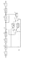
図1の(A)に示すように、例えばLCU(Largest Coding Unit)単位でラスター順にデブロッキングフィルタ処理を行う場合、上側ブロックであるLCUuにおいて、ブロック間の境界BBから所定ライン分の画像データがラインメモリに記憶されて、この画像データと、その後に得られる下側ブロックであるLCUlの画像データを用いて垂直フィルタ処理が行われる。例えば、図1の(B)に示すように、ブロック間の境界BBからそれぞれ3ライン分を垂直フィルタ処理の処理範囲として、境界BBから4ライン分の画像データを用いてフィルタ演算を行う場合、上側ブロックであるLCUuの境界BBから4ラインの画像データがラインメモリに記憶される。なお、図では、デブロッキングフィルタの対象画素を二重丸で示しており、デブロッキングフィルタのフィルタ処理範囲の上側境界を「DBU」、下側境界を「DBL」として示している。 As shown in FIG. 1A, for example, when deblocking filter processing is performed in raster order in units of LCU (Largest Coding Unit), image data for a predetermined line from the boundary BB between the blocks is stored in the LCUu that is the upper block. A vertical filter process is performed using the image data stored in the line memory and the image data of LCU1, which is the lower block obtained thereafter. For example, as shown in FIG. 1B, when performing a filter operation using image data for four lines from the boundary BB, with three lines each from the boundary BB between blocks as the processing range of the vertical filter processing, Four lines of image data from the boundary BB of LCUu, which is the upper block, are stored in the line memory. In the figure, the target pixel of the deblocking filter is indicated by a double circle, the upper boundary of the filter processing range of the deblocking filter is indicated as “DBU”, and the lower boundary is indicated as “DBL”.
このように、フィルタ演算に用いられる画像データをブロック間の境界BBから所定ラ イン分だけラインメモリに記憶しておくため、水平方向の画素数が増大するとラインメモリのメモリ容量が大きくなってしまっていた。 As described above, since the image data used for the filter calculation is stored in the line memory by a predetermined amount from the boundary BB between the blocks, the memory capacity of the line memory increases as the number of pixels in the horizontal direction increases. It was.
<2.画像符号化装置に適用した場合の構成>
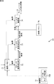
図2は、本技術の画像処理装置を画像符号化装置に適用した場合の構成を示している。画像符号化装置10は、アナログ/ディジタル変換部(A/D変換部)11、画面並び替えバッファ12、減算部13、直交変換部14、量子化部15、可逆符号化部16、蓄積バッファ17、レート制御部18を備えている。さらに、画像符号化装置10は、逆量子化部21、逆直交変換部22、加算部23、デブロッキングフィルタ処理部24、フレームメモリ25、セレクタ26、イントラ予測部31、動き予測・補償部32、予測画像・最適モード選択部33を備えている。
<2. Configuration when applied to an image encoding device>
FIG. 2 shows a configuration when the image processing apparatus of the present technology is applied to an image encoding apparatus. The
A/D変換部11は、アナログの画像信号をディジタルの画像データに変換して画面並べ替えバッファ12に出力する。
The A / D converter 11 converts an analog image signal into digital image data and outputs the digital image data to the
画面並べ替えバッファ12は、A/D変換部11から出力された画像データに対してフレームの並べ替えを行う。画面並べ替えバッファ12は、符号化処理に係るGOP(Group of Pictures)構造に応じてフレームの並べ替えを行い、並べ替え後の画像データを減算部13とイントラ予測部31と動き予測・補償部32に出力する。
The
減算部13には、画面並べ替えバッファ12から出力された画像データと、後述する予測画像・最適モード選択部33で選択された予測画像データが供給される。減算部13は、画面並べ替えバッファ12から出力された画像データと予測画像・最適モード選択部33から供給された予測画像データとの差分である予測誤差データを算出して、直交変換部14に出力する。
The
直交変換部14は、減算部13から出力された予測誤差データに対して、離散コサイン変換(DCT;Discrete Cosine Transform)、カルーネン・レーベ変換等の直交変換処理を行う。直交変換部14は、直交変換処理を行うことにより得られた変換係数データを量子化部15に出力する。
The
量子化部15には、直交変換部14から出力された変換係数データと、後述するレート制御部18からレート制御信号が供給されている。量子化部15は変換係数データの量子化を行い、量子化データを可逆符号化部16と逆量子化部21に出力する。また、量子化部15は、レート制御部18からのレート制御信号に基づき量子化パラメータ(量子化スケール)を切り替えて、量子化データのビットレートを変化させる。
The
可逆符号化部16には、量子化部15から出力された量子化データと、後述するイントラ予測部31と動き予測・補償部32および予測画像・最適モード選択部33から予測モード情報が供給される。なお、予測モード情報には、イントラ予測またはインター予測に応じて、予測ブロックサイズを識別可能とするマクロブロックタイプ、予測モード、動きベクトル情報、参照ピクチャ情報等が含まれる。可逆符号化部16は、量子化データに対して例えば可変長符号化、または算術符号化等により可逆符号化処理を行い、符号化ストリームを生成して蓄積バッファ17に出力する。また、可逆符号化部16は、予測モード情報を可逆符号化して、符号化ストリームのヘッダ情報に付加する。
The
蓄積バッファ17は、可逆符号化部16からの符号化ストリームを蓄積する。また、蓄積バッファ17は、蓄積した符号化ストリームを伝送路に応じた伝送速度で出力する。
The
レート制御部18は、蓄積バッファ17の空き容量の監視を行い、空き容量に応じてレート制御信号を生成して量子化部15に出力する。レート制御部18は、例えば蓄積バッファ17から空き容量を示す情報を取得する。レート制御部18は空き容量が少なくなっているとき、レート制御信号によって量子化データのビットレートを低下させる。また、レート制御部18は蓄積バッファ17の空き容量が十分大きいとき、レート制御信号によって量子化データのビットレートを高くする。
The
逆量子化部21は、量子化部15から供給された量子化データの逆量子化処理を行う。逆量子化部21は、逆量子化処理を行うことで得られた変換係数データを逆直交変換部2 2に出力する。
The inverse quantization unit 21 performs an inverse quantization process on the quantized data supplied from the
逆直交変換部22は、逆量子化部21から供給された変換係数データの逆直交変換処理を行うことで得られたデータを加算部23に出力する。
The inverse
加算部23は、逆直交変換部22から供給されたデータと予測画像・最適モード選択部33から供給された予測画像データを加算して復号画像データを生成して、デブロッキングフィルタ処理部24とフレームメモリ25に出力する。
The adding
デブロッキングフィルタ処理部24は、画像の符号化時に生じるブロック歪みを減少させるためのフィルタ処理を行う。デブロッキングフィルタ処理部24は、加算部23から供給された復号画像データからブロック歪みを除去するフィルタ処理を行い、フィルタ処理後の画像データをフレームメモリ25に出力する。また、デブロッキングフィルタ処理部24は、垂直方向のブロック間の境界検出によって検出された境界に応じて、境界の上側に位置するブロックにおけるフィルタ演算に用いる画像範囲を制御する。このように、フィルタ演算に用いる画像範囲を制御することで、デブロッキングフィルタ処理部24は、画像データを記憶するラインメモリのメモリ容量を削減しても、垂直フィルタ処理を行えるようにする。なお、詳細は後述する。
The deblocking
フレームメモリ25は、加算部23から供給された復号画像データとデブロッキングフィルタ処理部24から供給されたフィルタ処理後の復号画像データを参照画像の画像データとして保持する。
The
セレクタ26は、イントラ予測を行うためにフレームメモリ25から読み出されたフィルタ処理前の参照画像データをイントラ予測部31に供給する。また、セレクタ26は、インター予測を行うためフレームメモリ25から読み出されたフィルタ処理後の参照画像データを動き予測・補償部32に供給する。
The selector 26 supplies the pre-filtering reference image data read from the
イントラ予測部31は、画面並べ替えバッファ12から出力された符号化対象画像の画像データとフレームメモリ25から読み出したフィルタ処理前の参照画像データを用いて、候補となる全てのイントラ予測モードのイントラ予測処理を行う。さらに、イントラ予測部31は、各イントラ予測モードに対してコスト関数値を算出して、算出したコスト関数値が最小となるイントラ予測モード、すなわち符号化効率が最良となるイントラ予測モードを、最適イントラ予測モードとして選択する。イントラ予測部31は、最適イントラ予測モードで生成された予測画像データと最適イントラ予測モードに関する予測モード情報、および最適イントラ予測モードでのコスト関数値を予測画像・最適モード選択部33に出力する。また、イントラ予測部31は、後述するようにコスト関数値の算出で用いる発生符号量を得るため、各イントラ予測モードのイントラ予測処理において、イントラ予測モードに関する予測モード情報を可逆符号化部16に出力する。
The
動き予測・補償部32は、マクロブロックに対応する全ての予測ブロックサイズで動き予測・補償処理を行う。動き予測・補償部32は、画面並べ替えバッファ12から読み出された符号化対象画像における各予測ブロックサイズの画像毎に、フレームメモリ25から読み出されたフィルタ処理後の参照画像データを用いて動きベクトルを検出する。さらに、動き予測・補償部32は、検出した動きベクトルに基づいて復号画像に動き補償処理を施して予測画像の生成を行う。また、動き予測・補償部32は、各予測ブロックサイズに対してコスト関数値を算出して、算出したコスト関数値が最小となる予測ブロックサイズ、すなわち符号化効率が最良となる予測ブロックサイズを、最適インター予測モードとして選択する。動き予測・補償部32は、最適インター予測モードで生成された予測画像データと最適インター予測モードに関する予測モード情報、および最適インター予測モー ドでのコスト関数値を予測画像・最適モード選択部33に出力する。また、動き予測・補償部32は、コスト関数値の算出で用いる発生符号量を得るため、各予測ブロックサイズでのインター予測処理において、インター予測モードに関する予測モード情報を可逆符号化部16に出力する。なお、動き予測・補償部32は、インター予測モードとして、スキップドマクロブロックやダイレクトモードでの予測も行う。
The motion prediction /
予測画像・最適モード選択部33は、イントラ予測部31から供給されたコスト関数値と動き予測・補償部32から供給されたコスト関数値を、マクロブロック単位で比較して、コスト関数値が少ない方を、符号化効率が最良となる最適モードとして選択する。また、予測画像・最適モード選択部33は、最適モードで生成した予測画像データを減算部13と加算部23に出力する。さらに、予測画像・最適モード選択部33は、最適モードの予測モード情報を可逆符号化部16に出力する。なお、予測画像・最適モード選択部33は、スライス単位でイントラ予測またはインター予測を行うようにしてもよい。
The predicted image / optimum mode selection unit 33 compares the cost function value supplied from the
なお、請求項における符号化部は、予測画像データを生成するイントラ予測部31や動き予測・補償部32、予測画像・最適モード選択部33、減算部13、直交変換部14、量子化部15、可逆符号化部16等で構成される。
The encoding unit in the claims includes an
<3.画像符号化装置の動作>
図3は、画像符号化処理動作を示すフローチャートである。ステップST11において、A/D変換部11は入力された画像信号をA/D変換する。
<3. Operation of Image Encoding Device>
FIG. 3 is a flowchart showing the image encoding processing operation. In step ST11, the A / D converter 11 performs A / D conversion on the input image signal.
ステップST12において画面並べ替えバッファ12は、画面並べ替えを行う。画面並べ替えバッファ12は、A/D変換部11より供給された画像データを記憶し、各ピクチャの表示する順番から符号化する順番への並べ替えを行う。
In step ST12, the
ステップST13において減算部13は、予測誤差データの生成を行う。減算部13は、ステップST12で並べ替えられた画像の画像データと予測画像・最適モード選択部33で選択された予測画像データとの差分を算出して予測誤差データを生成する。予測誤差データは、元の画像データに比べてデータ量が小さい。したがって、画像をそのまま符号化する場合に比べて、データ量を圧縮することができる。なお、予測画像・最適モード選択部33でイントラ予測部31から供給された予測画像と動き予測・補償部32からの予測画像の選択がスライス単位で行われるとき、イントラ予測部31から供給された予測画像が選択されたスライスでは、イントラ予測が行われる。また、動き予測・補償部32からの予測画像が選択されたスライスでは、インター予測が行われる。
In step ST13, the
ステップST14において直交変換部14は、直交変換処理を行う。直交変換部14は、減算部13から供給された予測誤差データを直交変換する。具体的には、予測誤差データに対して離散コサイン変換、カルーネン・レーベ変換等の直交変換が行われ、変換係数データを出力する。
In step ST14, the
ステップST15において量子化部15は、量子化処理を行う。量子化部15は、変換係数データを量子化する。量子化に際しては、後述するステップST25の処理で説明されるように、レート制御が行われる。
In step ST15, the
ステップST16において逆量子化部21は、逆量子化処理を行う。逆量子化部21は、量子化部15により量子化された変換係数データを量子化部15の特性に対応する特性で逆量子化する。
In step ST16, the inverse quantization unit 21 performs an inverse quantization process. The inverse quantization unit 21 inversely quantizes the transform coefficient data quantized by the
ステップST17において逆直交変換部22は、逆直交変換処理を行う。逆直交変換部 22は、逆量子化部21により逆量子化された変換係数データを直交変換部14の特性に対応する特性で逆直交変換する。
In step ST17, the inverse
ステップST18において加算部23は、復号画像データの生成を行う。加算部23は、予測画像・最適モード選択部33から供給された予測画像データと、この予測画像と対応する位置の逆直交変換後のデータを加算して、復号画像データを生成する。
In step ST18, the adding
ステップST19においてデブロッキングフィルタ処理部24は、デブロッキングフィルタ処理を行う。デブロッキングフィルタ処理部24は、加算部23より出力された復号画像データをフィルタリングしてブロック歪みを除去する。また、デブロッキングフィルタ処理部24は、画像データを記憶するラインメモリのメモリ容量を削減しても、垂直フィルタ処理を行えるようする。具体的には、デブロッキングフィルタ処理部24は、垂直方向のブロック間の境界検出によって検出された境界に応じて、境界の上側に位置するブロックにおけるフィルタ演算に用いる画像範囲を制御する。
In step ST19, the deblocking
ステップST20においてフレームメモリ25は、復号画像データを記憶する。フレームメモリ25は、デブロッキングフィルタ処理前の復号画像データを記憶する。
In step ST20, the
ステップST21においてイントラ予測部31と動き予測・補償部32は、それぞれ予測処理を行う。すなわち、イントラ予測部31は、イントラ予測モードのイントラ予測処理を行い、動き予測・補償部32は、インター予測モードの動き予測・補償処理を行う。この処理により、候補となる全ての予測モードでの予測処理がそれぞれ行われ、候補となる全ての予測モードでのコスト関数値がそれぞれ算出される。そして、算出されたコスト関数値に基づいて、最適イントラ予測モードと最適インター予測モードが選択され、選択された予測モードで生成された予測画像とそのコスト関数および予測モード情報が予測画像・最適モード選択部33に供給される。
In step ST21, the
ステップST22において予測画像・最適モード選択部33は、予測画像データの選択を行う。予測画像・最適モード選択部33は、イントラ予測部31および動き予測・補償部32より出力された各コスト関数値に基づいて、符号化効率が最良となる最適モードに決定する。さらに、予測画像・最適モード選択部33は、決定した最適モードの予測画像データを選択して、減算部13と加算部23に供給する。この予測画像が、上述したように、ステップST13,ST18の演算に利用される。
In step ST22, the predicted image / optimum mode selection unit 33 selects predicted image data. The predicted image / optimum mode selection unit 33 determines the optimal mode with the best coding efficiency based on the cost function values output from the
ステップST23において可逆符号化部16は、可逆符号化処理を行う。可逆符号化部16は、量子化部15より出力された量子化データを可逆符号化する。すなわち、量子化データに対して可変長符号化や算術符号化等の可逆符号化が行われて、データ圧縮される。このとき、上述したステップST22において可逆符号化部16に入力された予測モード情報(例えばマクロブロックタイプや予測モード、動きベクトル情報、参照ピクチャ情報等を含む)なども可逆符号化される。さらに、量子化データを可逆符号化して生成された符号化ストリームのヘッダ情報に、予測モード情報の可逆符号化データが付加される。
In step ST23, the
ステップST24において蓄積バッファ17は、蓄積処理を行い符号化ストリームを蓄積する。この蓄積バッファ17に蓄積された符号化ストリームは適宜読み出され、伝送路を介して復号側に伝送される。
In step ST24, the
ステップST25においてレート制御部18は、レート制御を行う。レート制御部18は、蓄積バッファ17で符号化ストリームを蓄積するとき、オーバーフローまたはアンダーフローが蓄積バッファ17で発生しないように、量子化部15の量子化動作のレートを制御する。
In step ST25, the
次に、図3のステップST21における予測処理を説明する。イントラ予測部31はイントラ予測処理を行う。イントラ予測部31は処理対象のブロックの画像を、候補となる全てのイントラ予測モードでイントラ予測する。なお、イントラ予測において参照される参照画像の画像データは、デブロッキングフィルタ処理部24によりフィルタ処理が行われることなくフレームメモリ25に記憶されている参照画像データが用いられる。イントラ予測処理の詳細は後述するが、この処理により、候補となる全てのイントラ予測モードでイントラ予測が行われ、候補となる全てのイントラ予測モードに対してコスト関数値が算出される。そして、算出されたコスト関数値に基づいて、全てのイントラ予測モードの中から、符号化効率が最良となる1つのイントラ予測モードが選択される。動き予測・補償部32はインター予測処理を行う。動き予測・補償部32は、フレームメモリ25に記憶されているフィルタ処理後の参照画像データを用いて、候補となる全てのインター予測モード(全ての予測ブロックサイズ)のインター予測処理を行う。インター予測処理の詳細は後述するが、この処理により、候補となる全てのインター予測モードで予測処理が行われ、候補となる全てのインター予測モードに対してコスト関数値が算出される。そして、算出されたコスト関数値に基づいて、全てのインター予測モードの中から、符号化効率が最良となる1つのインター予測モードが選択される。
Next, the prediction process in step ST21 of FIG. 3 will be described. The
図4のフローチャートを参照してイントラ予測処理について説明する。ステップST31でイントラ予測部31は、各予測モードのイントラ予測を行う。イントラ予測部31は、フレームメモリ25に記憶されているフィルタ処理前の復号画像データを用いて、イントラ予測モード毎に予測画像データを生成する。
The intra prediction process will be described with reference to the flowchart of FIG. In step ST31, the
ステップST32でイントラ予測部31は、各予測モードに対するコスト関数値を算出する。例えば、候補となる全ての予測モードに対して、仮に可逆符号化処理までを行い、次の式(1)で表されるコスト関数値を各予測モードに対して算出する。
In step ST32, the
Cost(Mode∈Ω)=D+λ・R ・・・(1) Cost (Mode∈Ω) = D + λ · R (1)
Ωは、当該ブロック乃至マクロブロックを符号化するための候補となる予測モードの全体集合を示している。Dは、予測モードで符号化を行った場合の復号画像と入力画像との差分エネルギー(歪み)を示している。Rは、直交変換係数や予測モード情報等を含んだ発生符号量、λは、量子化パラメータQPの関数として与えられるラグランジュ乗数である。 Ω indicates the entire set of prediction modes that are candidates for encoding the block or macroblock. D indicates the differential energy (distortion) between the decoded image and the input image when encoding is performed in the prediction mode. R is a generated code amount including orthogonal transform coefficients and prediction mode information, and λ is a Lagrange multiplier given as a function of the quantization parameter QP.
また、候補となる全ての予測モードに対して、予測画像の生成、および、動きベクトル情報や予測モード情報などのヘッダビットまでを算出し、次の式(2)で表されるコスト関数値を各予測モードに対して算出する。 Further, for all prediction modes that are candidates, the generation of prediction images and the calculation of up to header bits such as motion vector information and prediction mode information are performed, and the cost function value represented by the following equation (2) is calculated. Calculate for each prediction mode.
Cost(Mode∈Ω)=D+QPtoQuant(QP)・Header_Bit ・・・(2) Cost (Mode∈Ω) = D + QPtoQuant (QP) · Header_Bit (2)
Ωは、当該ブロック乃至マクロブロックを符号化するための候補となる予測モードの全体集合を示している。Dは、予測モードで符号化を行った場合の復号画像と入力画像との差分エネルギー(歪み)を示している。Header_Bitは、予測モードに対するヘッダビット、QPtoQuantは、量子化パラメータQPの関数として与えられる関数である。 Ω indicates the entire set of prediction modes that are candidates for encoding the block or macroblock. D indicates the differential energy (distortion) between the decoded image and the input image when encoding is performed in the prediction mode. Header_Bit is a header bit for the prediction mode, and QPtoQuant is a function given as a function of the quantization parameter QP.
ステップST33でイントラ予測部31は、最適イントラ予測モードを決定する。イントラ予測部31は、ステップST32において算出されたコスト関数値に基づいて、それらの中から、コスト関数値が最小値である1つのイントラ予測モードを選択して最適イントラ予測モードに決定する。
In step ST33, the
次に、図5のフローチャートを参照して、インター予測処理について説明する。ステップST41で動き予測・補償部32は、各予測モードに対して動きベクトルと参照画像をそれぞれ決定する。すなわち、動き予測・補償部32は、各予測モードの処理対象のブロックについて、動きベクトルと参照画像をそれぞれ決定する。
Next, the inter prediction process will be described with reference to the flowchart of FIG. In step ST41, the motion prediction /
ステップST42で動き予測・補償部32は、各予測モードに対して動き補償を行う。動き予測・補償部32は、各予測モード(各予測ブロックサイズ)について、ステップST41で決定された動きベクトルに基づいて、参照画像に対する動き補償を行い、各予測モードについて予測画像データを生成する。
In step ST42, the motion prediction /
ステップST43で動き予測・補償部32は、各予測モードに対して動きベクトル情報の生成を行う。動き予測・補償部32は、各予測モードで決定された動きベクトルについて、符号化ストリームに含める動きベクトル情報を生成する。例えば、メディアン予測等を用いて予測動きベクトルを決定して、動き予測により検出した動きベクトルと予測動きベクトルの差を示す動きベクトル情報を生成する。このようにして生成された動きベクトル情報は、次のステップST44におけるコスト関数値の算出にも用いられて、最終的に予測画像・最適モード選択部33で対応する予測画像が選択された場合には、予測モード情報に含まれて可逆符号化部16へ出力される。
In step ST43, the motion prediction /
ステップST44で動き予測・補償部32は、各インター予測モードに対して、コスト関数値の算出を行う。動き予測・補償部32は、上述した式(1)または式(2)を用いてコスト関数値の算出を行う。
In step ST44, the motion prediction /
ステップST45で動き予測・補償部32は、最適インター予測モードを決定する。動き予測・補償部32は、ステップST44において算出されたコスト関数値に基づいて、それらの中から、コスト関数値が最小値である1つの予測モードを選択して最適インター予測モードに決定する。
In step ST45, the motion prediction /
<4.画像復号装置に適用した場合の構成>
入力画像を符号化して生成された符号化ストリームは、所定の伝送路や記録媒体等を介して画像復号装置に供給されて復号される。
<4. Configuration when applied to an image decoding device>
An encoded stream generated by encoding an input image is supplied to an image decoding device via a predetermined transmission path, a recording medium, and the like and decoded.
図6は、画像復号装置の構成を示している。画像復号装置50は、蓄積バッファ51、可逆復号部52、逆量子化部53、逆直交変換部54、加算部55、デブロッキングフィルタ処理部56、画面並べ替えバッファ57、D/A変換部58を備えている。さらに、画像復号装置50は、フレームメモリ61、セレクタ62,65、イントラ予測部63、動き補償部64を備えている。
FIG. 6 shows the configuration of the image decoding apparatus. The
蓄積バッファ51は、伝送されてきた符号化ストリームを蓄積する。可逆復号部52は、蓄積バッファ51より供給された符号化ストリームを、図2の可逆符号化部16の符号化方式に対応する方式で復号する。また、可逆復号部52は、符号化ストリームのヘッダ情報を復号して得られた予測モード情報をイントラ予測部63や動き補償部64に出力する。
The accumulation buffer 51 accumulates the transmitted encoded stream. The
逆量子化部53は、可逆復号部52で復号された量子化データを、図2の量子化部15の量子化方式に対応する方式で逆量子化する。逆直交変換部54は、図2の直交変換部14の直交変換方式に対応する方式で逆量子化部53の出力を逆直交変換して加算部55に出力する。
The
加算部55は、逆直交変換後のデータとセレクタ65から供給される予測画像データを加算して復号画像データを生成してデブロッキングフィルタ処理部56とフレームメモリ61に出力する。 The adding unit 55 adds the data after inverse orthogonal transformation and the predicted image data supplied from the selector 65 to generate decoded image data, and outputs the decoded image data to the deblocking filter processing unit 56 and the frame memory 61.
デブロッキングフィルタ処理部56は、加算部55から供給された復号画像データに対して、図2のデブロッキングフィルタ処理部24と同様にフィルタ処理を行い、ブロック歪みを除去して画面並べ替えバッファ57とフレームメモリ61に出力する。
The deblocking filter processing unit 56 performs a filtering process on the decoded image data supplied from the adding unit 55 in the same manner as the deblocking
画面並べ替えバッファ57は、画像の並べ替えを行う。すなわち、図2の画面並べ替えバッファ12により符号化の順番のために並べ替えられたフレームの順番が、元の表示の順番に並べ替えられて、D/A変換部58に出力される。
The
D/A変換部58は、画面並べ替えバッファ57から供給された画像データをD/A変換し、図示せぬディスプレイに出力することで画像を表示させる。
The D / A conversion unit 58 performs D / A conversion on the image data supplied from the
フレームメモリ61は、加算部55から供給されたフィルタ処理前の復号画像データとデブロッキングフィルタ処理部56から供給されたフィルタ処理後の復号画像データとを、参照画像の画像データとして保持する。 The frame memory 61 holds the decoded image data before the filtering process supplied from the adding unit 55 and the decoded image data after the filtering process supplied from the deblocking filter processing unit 56 as the image data of the reference image.
セレクタ62は、可逆復号部52から供給された予測モード情報に基づき、イントラ予測が行われた予測ブロックの復号が行われるとき、フレームメモリ61から読み出されたフィルタ処理前の参照画像データをイントラ予測部63に供給する。また、セレクタ26は、可逆復号部52から供給された予測モード情報に基づき、インター予測が行われた予測ブロックの復号が行われるとき、フレームメモリ61から読み出されたフィルタ処理後の参照画像データを動き補償部64に供給する。
Based on the prediction mode information supplied from the
イントラ予測部63は、可逆復号部52から供給された予測モード情報に基づいて予測画像の生成を行い、生成した予測画像データをセレクタ65に出力する。
The intra prediction unit 63 generates a predicted image based on the prediction mode information supplied from the
動き補償部64は、可逆復号部52から供給された予測モード情報に基づいて、動き補償を行い、予測画像データを生成してセレクタ65に出力する。すなわち、動き補償部64は、予測モード情報に含まれる動きベクトル情報と参照フレーム情報に基づいて、参照フレーム情報で示された参照画像に対して動きベクトル情報に基づく動きベクトルで動き補償を行い、予測画像データを生成する。
The
セレクタ65は、イントラ予測部63で生成された予測画像データを加算部55に供給する。また、セレクタ65は、動き補償部64で生成された予測画像データを加算部55に供給する。
The selector 65 supplies the predicted image data generated by the intra prediction unit 63 to the addition unit 55. Further, the selector 65 supplies the predicted image data generated by the
なお、請求項における復号部は、可逆復号部52、逆量子化部53、逆直交変換部54、加算部55、イントラ予測部63、動き補償部64等で構成される。
Note that the decoding unit in the claims includes a
<5.画像復号装置の動作>
次に、図7のフローチャートを参照して、画像復号装置50で行われる画像復号動作について説明する。
<5. Operation of Image Decoding Device>
Next, an image decoding operation performed by the
ステップST51で蓄積バッファ51は、伝送されてきた符号化ストリームを蓄積する。ステップST52で可逆復号部52は、可逆復号処理を行う。可逆復号部52は、蓄積バッファ51から供給される符号化ストリームを復号する。すなわち、図2の可逆符号化部16により符号化された各ピクチャの量子化データが得られる。また、可逆復号部52 、符号化ストリームのヘッダ情報に含まれている予測モード情報の可逆復号を行い、得られた予測モード情報をデブロッキングフィルタ処理部56やセレクタ62,65に供給する。さらに、可逆復号部52は、予測モード情報がイントラ予測モードに関する情報である場合、予測モード情報をイントラ予測部63に出力する。また、可逆復号部52は、予測モード情報がインター予測モードに関する情報である場合、予測モード情報を動き補償部64に出力する。
In step ST51, the accumulation buffer 51 accumulates the transmitted encoded stream. In step ST52, the
ステップST53において逆量子化部53は、逆量子化処理を行う。逆量子化部53は、可逆復号部52により復号された量子化データを、図2の量子化部15の特性に対応する特性で逆量子化する。
In step ST53, the
ステップST54において逆直交変換部54は、逆直交変換処理を行う。逆直交変換部54は、逆量子化部53により逆量子化された変換係数データを、図2の直交変換部14の特性に対応する特性で逆直交変換する。
In step ST54, the inverse
ステップST55において加算部55は、復号画像データの生成を行う。加算部55は、逆直交変換処理を行うことにより得られたデータと、後述するステップST59で選択された予測画像データを加算して復号画像データを生成する。これにより元の画像が復号される。 In step ST55, the adding unit 55 generates decoded image data. The adder 55 adds the data obtained by performing the inverse orthogonal transform process and the predicted image data selected in step ST59 described later to generate decoded image data. As a result, the original image is decoded.
ステップST56においてデブロッキングフィルタ処理部56は、デブロッキングフィルタ処理を行う。デブロッキングフィルタ処理部56は、加算部55より出力された復号画像データのフィルタ処理を行い、復号画像に含まれているブロック歪みを除去する。 In step ST56, the deblocking filter processing unit 56 performs deblocking filter processing. The deblocking filter processing unit 56 performs a filtering process on the decoded image data output from the adding unit 55 to remove block distortion included in the decoded image.
ステップST57においてフレームメモリ61は、復号画像データの記憶処理を行う。 In step ST57, the frame memory 61 performs a process of storing decoded image data.
ステップST58においてイントラ予測部63と動き補償部64は、予測処理を行う。イントラ予測部63と動き補償部64は、可逆復号部52から供給される予測モード情報に対応してそれぞれ予測処理を行う。
In step ST58, the intra prediction unit 63 and the
すなわち、可逆復号部52からイントラ予測の予測モード情報が供給された場合、イントラ予測部63は、予測モード情報に基づいてイントラ予測処理を行い、予測画像データを生成する。また、可逆復号部52からインター予測の予測モード情報が供給された場合、動き補償部64は、予測モード情報に基づき動き補償を行い、予測画像データを生成する。
That is, when prediction mode information for intra prediction is supplied from the
ステップST59において、セレクタ65は予測画像データの選択を行う。すなわち、セレクタ65は、イントラ予測部63から供給された予測画像と動き補償部64で生成された予測画像データを選択して加算部55に供給して、上述したように、ステップST55において逆直交変換部54の出力と加算させる。
In step ST59, the selector 65 selects predicted image data. That is, the selector 65 selects the prediction image supplied from the intra prediction unit 63 and the prediction image data generated by the
ステップST60において画面並べ替えバッファ57は、画面並べ替えを行う。すなわち画面並べ替えバッファ57は、図2の画像符号化装置10の画面並べ替えバッファ12により符号化のために並べ替えられたフレームの順序が、元の表示の順序に並べ替えられる。
In step ST60, the
ステップST61において、D/A変換部58は、画面並べ替えバッファ57からの画像データをD/A変換する。この画像が図示せぬディスプレイに出力され、画像が表示される。
In step ST61, the D / A converter 58 D / A converts the image data from the
<6.デブロッキングフィルタ処理部の基本的な動作>
一般的に、H.264/AVCまたはHEVCなどの画像符号化方式におけるデブロックフィルタ処理は、フィルタリング要否判定を行い、フィルタリングが必要と判別されたブロック間の境界に対してフィルタリング処理を行う。
<6. Basic Operation of Deblocking Filter Processing Unit>
In general, H.C. In the deblocking filter processing in an image encoding scheme such as H.264 / AVC or HEVC, filtering necessity determination is performed, and filtering processing is performed on a boundary between blocks determined to require filtering.
ブロック間の境界は、水平方向にブロック間の境界検出を行って検出される境界、すなわち左右に隣接するブロック間の境界(以下「垂直境界」という)含む。また、ブロック間の境界は、垂直方向にブロック間の境界検出を行って検出される境界、すなわち上下に隣接するブロック間の境界(以下「ライン境界」という)を含む。 The boundary between blocks includes a boundary detected by detecting a boundary between blocks in the horizontal direction, that is, a boundary between blocks adjacent to the left and right (hereinafter referred to as “vertical boundary”). In addition, the boundary between blocks includes a boundary detected by performing boundary detection between blocks in the vertical direction, that is, a boundary between vertically adjacent blocks (hereinafter referred to as “line boundary”).
図8は、境界を挟んで隣接する2つのブロックBKaおよびBKb内の画素の一例を示す説明図である。ここでは垂直境界を例にとって説明するが、ライン境界にも同等に適用可能である。図8の例において、ブロックBKa内の画素の画像データを、「pi,j」という記号で示されている。iは画素の列インデックス、jは画素の行のインデックスである。また、最小符号化処理単位は、8画素×8画素のブロック単位として、列インデックスiは、垂直境界に近い列から順に(右から左へ)0,1,2,3と付番されている。行インデックスjは、上から下へ0,1,2,…,7と付番されている。なお、ブロックBKaの左半分は図中で省略されている。一方、ブロックBKb内の画素の画像データは、「qk,j」という記号で示されている。kは画素の列インデックス、jは画素の行インデックスである。列インデックスkは、垂直境界に近い列から順に(左から右へ)0,1,2,3と付番されている。なお、ブロックBKbの右半分もまた図中で省略されている。 FIG. 8 is an explanatory diagram illustrating an example of pixels in two blocks BKa and BKb that are adjacent to each other across a boundary. Here, a vertical boundary will be described as an example, but the present invention can be equally applied to a line boundary. In the example of FIG. 8, the image data of the pixels in the block BKa is indicated by the symbol “pi, j”. i is the column index of the pixel, and j is the index of the row of the pixel. The minimum encoding processing unit is a block unit of 8 pixels × 8 pixels, and the column index i is numbered as 0, 1, 2, 3 in order from the column close to the vertical boundary (from right to left). . The row index j is numbered 0, 1, 2,..., 7 from top to bottom. Note that the left half of the block BKa is omitted in the figure. On the other hand, the image data of the pixels in the block BKb is indicated by the symbol “qk, j”. k is the column index of the pixel, and j is the row index of the pixel. The column index k is numbered 0, 1, 2, 3 in order from the column close to the vertical boundary (from left to right). The right half of the block BKb is also omitted in the figure.
境界がデブロックフィルタを適用すべきと判定された場合、例えば垂直境界については当該境界の左右の画素のフィルタリング処理が行われる。輝度成分については、画像データの値に応じてフィルタ強度が強(strong)フィルタと弱(weak)フィルタとの間で切り替えられる。 When it is determined that the deblocking filter should be applied to the boundary, for example, for the vertical boundary, the filtering processing of the pixels on the left and right of the boundary is performed. For the luminance component, the filter strength is switched between a strong filter and a weak filter in accordance with the value of the image data.
・輝度成分のフィルタリング
強度選択では、式(3)乃至式(5)の判別条件を満たすか否かを1ラインごと(または1列毎)判定して、式(3)乃至式(5)の判別条件を全て満たす場合には強フィルタ、何れか1つでも判定条件が満たされない場合には弱フィルタが選択される。
-Luminance component filtering In intensity selection, it is determined for each line (or for each column) whether or not the discrimination conditions of Equations (3) to (5) are satisfied, and Equations (3) to (5) A strong filter is selected when all the determination conditions are satisfied, and a weak filter is selected when any one of the determination conditions is not satisfied.

なお、式(3)における「d」は、式(6)に基づいて算出される値である。また、式(4)(5)における「β」と、式(5)における「tc」は、表1に示すように、量子化パラメータQに基づいて設定される値である。 Note that “d” in Equation (3) is a value calculated based on Equation (6). Further, “β” in the equations (4) and (5) and “tc” in the equation (5) are values set based on the quantization parameter Q as shown in Table 1.
弱フィルタリングでは、式(7)乃至式(11)の演算を行うことで、フィルタ処理範囲の各画素の輝度成分が算出される。 In weak filtering, the luminance component of each pixel in the filter processing range is calculated by performing the calculations of Expressions (7) to (11).
強フィルタリングでは、式(12)乃至式(18)の演算を行うことで、フィルタ処理範囲の各画素の輝度成分が算出される。 In strong filtering, the luminance component of each pixel in the filter processing range is calculated by performing the calculations of Expressions (12) to (18).
また、色差成分のフィルタリングでは、式(19)乃至式(21)の演算を行うことで、 フィルタ処理範囲の各画素の色差成分が算出される。 In the color difference component filtering, the color difference component of each pixel in the filter processing range is calculated by performing the calculations of Expressions (19) to (21).
なお、上述の式において「Clip1Y」「Clip1c」は、式(22),(23)の演算を示しており、式(22)(23)の「Clip3(x,y,z)」は式(24)で決定される値を示している。 In the above formula, “Clip1Y” and “Clip1c” indicate the operations of the formulas (22) and (23), and “Clip3 (x, y, z)” of the formulas (22) and (23) is the formula ( The value determined in 24) is shown.
また、ライン境界については、垂直境界において水平方向に画素を用いてライン毎に行われている演算を、垂直方向に画素を用いて列毎に行いフィルタリング処理が行われる。
For the line boundary, a filtering process is performed by performing an operation performed for each line using pixels in the horizontal direction on the vertical boundary for each column using pixels in the vertical direction.
デブロッキングフィルタ処理において、ラインメモリが必要とされる処理は垂直フィルタ処理であり、以下、垂直フィルタ処理においてラインメモリのメモリ容量の削減について詳細に説明する。なお、画像符号化装置10のデブロッキングフィルタ処理部24と画像復号装置50のデブロッキングフィルタ処理部56は、同一の構成および同一の動作とされており、デブロッキングフィルタ処理部24についてのみ説明を行う。
In the deblocking filter process, the process that requires the line memory is the vertical filter process. Hereinafter, the reduction of the memory capacity of the line memory in the vertical filter process will be described in detail. Note that the deblocking
<7.デブロッキングフィルタ処理部の第1の実施の形態>
図9は、デブロッキングフィルタ処理部の第1の実施の形態の構成を例示している。デブロッキングフィルタ処理部24は、ラインメモリ241、ライン境界検出部242、フィルタ強度判定部243、係数メモリ244、フィルタ演算部245、フィルタ制御部246を備えている。
<7. First Embodiment of Deblocking Filter Processing Unit>
FIG. 9 illustrates the configuration of the first embodiment of the deblocking filter processing unit. The deblocking
ラインメモリ241は、フィルタ制御部246からの制御信号に基づき、加算部23から供給された画像データを記憶する。また、記憶している画像データを読み出して、ライン境界検出部242、フィルタ強度判定部243、フィルタ演算部245に出力する。
The line memory 241 stores the image data supplied from the adding
ライン境界検出部242は、垂直フィルタ処理を行うライン境界を検出する。ライン境界検出部242は、加算部23から供給された画像データやラインメモリ241から読み出された画像データを用いて上述のフィルタリング要否判定処理をブロック毎に行い、垂直フィルタ処理を行うライン境界を検出する。ライン境界検出部242は、検出結果をフィルタ強度判定部243に出力する。
The line
フィルタ強度判定部243は、上述のようにフィルタ強度の判定を行う。フィルタ強度判定部243は、垂直フィルタ処理を行うライン境界を挟んで隣接する2つのブロックの画像データを用いて、強フィルタリングまたは弱フィルタリングの何れの強度で垂直フィルタ処理を行うか判定して、判定結果をフィルタ演算部245に出力する。
The filter strength determination unit 243 determines the filter strength as described above. The filter strength determination unit 243 determines whether to perform the vertical filter processing with strong filtering or weak filtering using the image data of two blocks adjacent to each other with the line boundary on which vertical filtering is performed. The result is output to the
係数メモリ244は、デブロッキングフィルタ処理のフィルタ演算に用いるフィルタ係数を記憶している。
The
フィルタ演算部245は、加算部23から供給された画像データやラインメモリ241に記憶されている画像データ、および係数メモリ244から読み出したフィルタ係数を用いて、フィルタ強度判定部243で判定されたフィルタ強度でフィルタ演算を行う。フィルタ演算部245は、垂直フィルタ処理がなされた画像データをフレームメモリ25に出力する。また、フィルタ演算部245は、フィルタ制御部246から供給されたブロック境界判定結果に基づき、ライン境界の上側に位置するブロックにおけるフィルタ演算に用いる画像範囲を制御する。
The
フィルタ制御部246は、ラインメモリ241を制御して、ブロック内の下端側の所定ライン数分の画像データを記憶させる。また、記憶されている画像データの読み出しを行う。また、フィルタ制御部246はライン境界判定部2461を備えている。ライン境界判定部2461は、ラスタースキャン方向に順次処理が行われるブロック単位例えばLCU間のライン境界であるか判定して判定結果をフィルタ演算部245に出力する。フィルタ演算部245は、ラインメモリのメモリ容量が削減されていても垂直フィルタ処理を行うことができるように制御する。
The
図10は、デブロッキングフィルタ処理部の第1の実施の形態の動作を示している。ステップST71でデブロッキングフィルタ処理部24はライン境界の検出を行う。デブロッキングフィルタ処理部24は、垂直フィルタ処理を行うライン境界を検出する。
FIG. 10 shows the operation of the first embodiment of the deblocking filter processing unit. In step ST71, the deblocking
ステップST72でデブロッキングフィルタ処理部24は、フィルタ強度の判定を行う。デブロッキングフィルタ処理部24は、垂直フィルタ処理を行うライン境界についての、強フィルタと弱フィルタの何れのフィルタ強度とするか判定する。
In step ST72, the deblocking
ステップST73でデブロッキングフィルタ処理部24は、垂直フィルタ処理を行う境界がLCU間のライン境界であるか判別する。デブロッキングフィルタ処理部24は、垂直フィルタ処理を行う境界がLCU間のライン境界である場合はステップST74に進み、境界がLCU間のライン境界でない場合はステップST75に進む。
In step ST73, the deblocking
ステップST74でデブロッキングフィルタ処理部24は、範囲削減垂直フィルタ処理を行う。デブロッキングフィルタ処理部24は、上側に隣接するLCUに対してフィルタ演算に用いる画像範囲を削減して垂直フィルタ処理を行いステップST76に進む。
In step ST74, the deblocking
ステップST75でデブロッキングフィルタ処理部24は、通常垂直フィルタ処理を行う。デブロッキングフィルタ処理部24は、フィルタ演算に用いる画像範囲を削減することなく予め設定されたタップおよび係数を用いて垂直フィルタ処理を行ってステップST76に進む。
In step ST75, the deblocking
ステップST76でデブロッキングフィルタ処理部24は、境界の垂直フィルタ処理が完了したか判別する。デブロッキングフィルタ処理部24は、境界の各列の垂直フィルタ処理が完了していない場合にはステップST76に戻り、次の列の処理を行う。また、境界の各列の垂直フィルタ処理が完了した場合は、ステップST77に進む。
In step ST76, the deblocking
ステップST77でデブロッキングフィルタ処理部24は、画面の最後まで処理が完了したか判別する。デブロッキングフィルタ処理部24は、画面の最後まで処理が行われていない場合にはステップST71に戻り、新たな境界を検出して垂直フィルタ処理を行う。また、デブロッキングフィルタ処理部24は、画面の最後まで処理が行われた場合、11画面の処理を終了する。
In step ST77, the deblocking
[フィルタ演算部の構成と動作]
図11と図12はフィルタ演算部の構成を示している。フィルタ演算部245は、タップ変更垂直フィルタ処理を行う場合、画像データを記憶するライン数を削減しても、垂直フィルタ処理を行うことができるように、タップの画像データの変更またはタップ数の変更を行う。なお、図11は、タップの画像データを変更して垂直フィルタ処理を行う場合のフィルタ演算部の構成を示している。また、図12は、タップ数を変更して垂直フィルタ処理を行う場合のフィルタ演算部の構成を示している。
[Configuration and operation of filter operation unit]
11 and 12 show the configuration of the filter calculation unit. When performing the tap change vertical filter process, the
図11において、フィルタ演算部245は、データ記憶部2451とデータ選択部2452、および演算処理部2453を備えている。
In FIG. 11, the
データ記憶部2451は、ラインメモリのメモリ容量を削減した場合に、削減されているラインの位置のタップとして用いる画像データを記憶する。データ記憶部2451は、記憶している画像データを、削減されているラインの位置のタップの画像データとしてデータ選択部2452に出力する。 When the memory capacity of the line memory is reduced, the data storage unit 2451 stores image data used as a tap of the line position that has been reduced. The data storage unit 2451 outputs the stored image data to the data selection unit 2452 as the image data of the tap at the position of the reduced line.
データ選択部2452は、データ記憶部2451に記憶されている画像データと、ラインメモリに記憶されている画像データの選択を行い、選択した画像データを演算処理部2453に出力する。
The data selection unit 2452 selects the image data stored in the data storage unit 2451 and the image data stored in the line memory, and outputs the selected image data to the
演算処理部2453は、加算部23とデータ選択部2452から供給された画像データと係数メモリ244から読み出したフィルタ係数を用いて演算を行い、垂直フィルタ処理後の画像データを生成してフレームメモリ25に出力する。
The
図12において、フィルタ演算部245は、演算処理部2455と演算処理部2456を備えている。
In FIG. 12, the
演算処理部2455は所定のタップ数で演算処理を行い、垂直フィルタ処理後の画像データをデータ選択部2457に出力する。 The arithmetic processing unit 2455 performs arithmetic processing with a predetermined number of taps, and outputs the image data after the vertical filter processing to the data selection unit 2457.
演算処理部2456は、ラインメモリの削減に応じてタップ数を削減することで、削減されているラインの画像データを用いることなく演算処理を行い、垂直フィルタ処理後の画像データをデータ選択部2457に出力する。
The
データ選択部2457は、境界がLCU間のライン境界であるか否かに応じて、画像データの選択を行う。データ選択部2457は、境界がLCU間のライン境界でない場合、演算処理部2455から出力された画像データを選択する。また、データ選択部2457は、境界がLCU間のライン境界である場合、演算処理部2456から出力された画像データを選択する。
The data selection unit 2457 selects image data depending on whether the boundary is a line boundary between LCUs. The data selection unit 2457 selects the image data output from the arithmetic processing unit 2455 when the boundary is not a line boundary between LCUs. Further, the data selection unit 2457 selects the image data output from the
図13は、フィルタ演算部245の動作を説明するための図である。隣接する2つのブロックBKu,BKlの各画素の画像データを示している。ここで、垂直フィルタ処理のフィルタ処理範囲は、境界(ライン境界)BBからそれぞれ3画素の範囲として、境界BBからそれぞれ4画素をタップとしてフィルタ演算を行う。フィルタ強度判定によって強 フィルタリングが判定された場合、上述の式(12)乃至式(18)の演算を演算処理部2453,2455で列毎に行う。また、フィルタ強度判定によって弱フィルタリングが判定された場合、上述の式(7)乃至式(10)の演算を演算処理部2453,2455で列毎に行う。
FIG. 13 is a diagram for explaining the operation of the
LCU単位でラスター順にデブロッキングフィルタ処理を行う場合、垂直フィルタ処理が強フィルタリングと判定されて上述の式(12)乃至式(18)の演算を行うためには、図13の(A)に示すように境界BBの上側のブロックBKuにおいて、境界BBから4ライン分の画像データをラインメモリに記憶しておく必要がある。 When deblocking filter processing is performed in raster order in units of LCUs, in order for the vertical filter processing to be determined as strong filtering and to perform the calculations of the above formulas (12) to (18), as shown in FIG. Thus, in the block BKu above the boundary BB, it is necessary to store image data for four lines from the boundary BB in the line memory.
ここで、フィルタ演算部245は、境界BBの上側に位置するブロックにおけるフィルタ演算に用いる画像範囲を制御することで、ラインメモリのメモリ容量を削減しても、垂直フィルタ処理を行えるようにする。例えば、図13の(B)に示すように境界BBから3ライン分の画像データを記憶して、この記憶された画像データを用いて垂直フィルタ処理を行う。すなわち、図11に示す演算処理部2453は、式(25)の演算を行う。また、図12に示す演算処理部2456は、式(26)の演算を行い、データ選択部2457は、演算処理部2456からの画像データを選択して出力する。なお、式(25),(26)において、iは画素の列インデックスを示しており、フィルタ処理を8×8画素のブロック単位で行う場合「i=0乃至7」となる。
Here, the
演算処理部2453は、上側のブロックBKuにおいて、フィルタ処理範囲の上端の画素を上方向に複写して用いる。すなわち、データ記憶部2451に記憶したフィルタ処理範囲の上端の画素の画像データp2を画像データp3として用いることで、式(25)の演算によってフィルタ処理後の画像データp2i’を算出する。
In the upper block BKu, the
演算処理部2456では、タップ数を削減して、タップ数の削減に対応して変更されている係数を用いることで、式(26)の演算によってフィルタ処理後の画像データp2i’を算出する。この場合の係数の変更は、タップ範囲の上端の画素の複写に対応させて、画像データp2の係数を「3→5」に変更する。
The
なお、境界BBがLCU間のライン境界でない場合は、ラインメモリ241の画像データを用いる必要がないことから、フィルタ演算に用いる画像範囲を狭くすることなく従来と同様なフィルタ演算を行う。すなわち、図11に示す演算処理部2453は、従来と同様なフィルタ演算を行う。また、図12に示す演算処理部2455は、従来と同様なフィルタ演算を行い、データ選択部2457は、演算処理部2455からの画像データを選択して出力する。
When the boundary BB is not a line boundary between LCUs, it is not necessary to use the image data in the line memory 241. Therefore, the same filter calculation is performed without narrowing the image range used for the filter calculation. That is, the
このように、境界がラスタースキャン方向に順次処理が行われるブロックのライン境界である場合、フィルタ演算に用いる画像範囲を制御することで、ラインメモリのメモリ容量を削減しても、削減前と同様にデブロッキングフィルタ処理を行うことができる。また、例えば4K×2Kの画像における1ラインは、2K×1Kの画像の2ライン分に相当する。また、H.264/AVC方式では、4ライン分のラインメモリを備えており、4K ×2Kの画像における1ライン分のメモリ容量は、H.264/AVC方式の50%のメモリ容量に相当する。すなわち、高解像度画像においてメモリ容量の削減効果が高くなる。 In this way, when the boundary is a line boundary of a block that is sequentially processed in the raster scan direction, even if the memory capacity of the line memory is reduced by controlling the image range used for the filter operation, the same as before the reduction The deblocking filter process can be performed. For example, one line in a 4K × 2K image corresponds to two lines in a 2K × 1K image. H. The H.264 / AVC system includes a line memory for four lines, and the memory capacity for one line in a 4K × 2K image is H.264. This corresponds to a memory capacity of 50% of the H.264 / AVC format. That is, the effect of reducing the memory capacity is increased in a high resolution image.
<8.デブロッキングフィルタ処理部の第2の実施の形態>
デブロッキングフィルタ処理部の第2の実施の形態は、第1の実施の形態に対して、演算処理部2453と演算処理部2456の動作が相違する。
<8. Second Embodiment of Deblocking Filter Processing Unit>
The second embodiment of the deblocking filter processing unit differs from the first embodiment in the operations of the
強フィルタリングにおいて境界BBがLCU間のライン境界である場合、上述の式(12)乃至式(18)の演算を行う場合には、図13の(A)に示すように境界BBの上側のブロックBKuにおいて、境界BBから4ライン分の画像データをラインメモリに記憶しておく必要がある。 When the boundary BB is a line boundary between LCUs in the strong filtering, when performing the above-described equations (12) to (18), the block above the boundary BB is shown in FIG. In BKu, it is necessary to store image data for four lines from the boundary BB in the line memory.
ここで、フィルタ演算部245は、境界BBの上側に位置するブロックにおけるフィルタ演算に用いる画像範囲を制御することで、ラインメモリのメモリ容量を削減しても、垂直フィルタ処理を行えるようにする。例えば、図13の(B)に示すように境界BBから3ライン分の画像データを記憶して、この記憶された画像データを用いて垂直フィルタ処理を行う。すなわち、図11に示す演算処理部2453は、式(27)の演算を行う。また、図12に示す演算処理部2456は、式(28)の演算を行い、データ選択部2457は、演算処理部2456からの画像データを選択して出力する。なお、式(27),(28)において、iは画素の列インデックスを示しており、フィルタ処理を8×8画素のブロック単位で行う場合「i=0乃至7」となる。
Here, the
演算処理部2453は、上側のブロックBKuにおいて、フィルタ処理範囲の上端の画素を基準としてミラー複写を行う。すなわち、データ記憶部2451に画像データp1を記憶して、この画像データp1をフィルタ処理範囲の上端の画素を基準としてミラー複写して画像データp3として用いることで、式(27)の演算によってフィルタ処理後の画像データp2i’を算出する。
The
演算処理部2456では、タップ数を削減して、タップ数の削減に対応して変更されている係数を用いることで、式(28)の演算によってフィルタ処理後の画像データp2i’を算出する。この場合の係数の変更は、フィルタ処理範囲の上端の画素を基準としたミラー複写に対応させて、画像データp1の係数を「2→3」に変更する。
The
なお、境界BBがLCU間のライン境界でない場合は、ラインメモリ241の画像データを用いる必要がないことから、フィルタ演算に用いる画像範囲を狭くすることなく従来と同様なフィルタ演算を行う。すなわち、図11に示す演算処理部2453は、従来と同様なフィルタ演算を行う。また、図12に示す演算処理部2455は、従来と同様なフィルタ演算を行い、データ選択部2457は、演算処理部2455からの画像データを選択して出力する。
When the boundary BB is not a line boundary between LCUs, it is not necessary to use the image data in the line memory 241. Therefore, the same filter calculation is performed without narrowing the image range used for the filter calculation. That is, the
このように、境界がラスタースキャン方向に順次処理が行われるブロックのライン境界 である場合、フィルタ演算に用いる画像範囲を制御することで、第1の実施の形態と同様に、メモリ容量を削減してもデブロッキングフィルタ処理を行うことができる。 As described above, when the boundary is a line boundary of a block that is sequentially processed in the raster scan direction, the memory capacity can be reduced by controlling the image range used for the filter operation, as in the first embodiment. Even deblocking filter processing can be performed.
<9.デブロッキングフィルタ処理部の第3の実施の形態>
デブロッキングフィルタ処理部の第3の実施の形態は、第1,第2の実施の形態に対して、演算処理部2453と演算処理部2456の動作が相違する。
<9. Third Embodiment of Deblocking Filter Processing Unit>
The third embodiment of the deblocking filter processing unit is different from the first and second embodiments in the operations of the
図14は、フィルタ演算部245の動作を説明するための図である。隣接する2つのブロックBKu,BKlの各画素の画像データを示している。ここで、垂直フィルタ処理のフィルタ処理範囲は、境界(ライン境界)BBからそれぞれ3画素の範囲として、境界BBからそれぞれ4画素をタップとしてフィルタ演算を行う。フィルタ強度判定によって強フィルタリングが判定された場合、上述の式(12)乃至式(18)の演算を演算処理部2453,2455で列毎に行う。また、フィルタ強度判定によって弱フィルタリングが判定された場合、上述の式(7)乃至式(10)の演算を演算処理部2453,2455で列毎に行う。
FIG. 14 is a diagram for explaining the operation of the
LCU単位でラスター順にデブロッキングフィルタ処理を行う場合、垂直フィルタ処理が強フィルタリングと判定されて上述の式(12)乃至式(18)の演算を行うためには、図14の(A)に示すように境界BBの上側のブロックBKuにおいて、境界BBから4ライン分の画像データをラインメモリに記憶しておく必要がある。 When deblocking filter processing is performed in raster order in units of LCUs, in order for the vertical filter processing to be determined as strong filtering and to perform the calculations of the above formulas (12) to (18), as shown in FIG. Thus, in the block BKu above the boundary BB, it is necessary to store image data for four lines from the boundary BB in the line memory.
ここで、フィルタ演算部245は、フィルタ処理範囲と境界BBの上側に位置するブロックにおけるフィルタ演算に用いる画像範囲を制御することで、ラインメモリのメモリ容量を削減しても、垂直フィルタ処理を行えるようにする。例えば、図14の(B)に示すように、上側のブロックBKuにおけるフィルタ処理範囲を境界BBから2画素の範囲として、境界BBから2ライン分の画像データを記憶する。さらに、この記憶された画像データを用いて、第1の実施の形態と同様に垂直フィルタ処理を行う。すなわち、図11に示す演算処理部2453は、式(29)(30)の演算を行う。また、図12に示す演算処理部2456は、式(31)(32)の演算を行い、データ選択部2457は、演算処理部2456からの画像データを選択して出力する。なお、式(29)乃至(32)において、iは画素の列インデックスを示しており、フィルタ処理を8×8画素のブロック単位で行う場合「i=0乃至7」となる。
Here, the
演算処理部2453は、上側のブロックBKuにおいて、フィルタ処理範囲の上端の画素を上方向に複写して用いる。すなわち、データ記憶部2451に記憶したフィルタ処理範囲の上端の画素の画像データp1を画像データp2として用いることで、式(29)(30)の演算によってフィルタ処理後の画像データp1i’,p0i’を算出する。
In the upper block BKu, the
演算処理部2456では、タップ数を削減して、タップ数の削減に対応して変更されている係数を用いることで、式(31)(32)の演算によってフィルタ処理後の画像データp1i’,p0i’を算出する。この場合の係数の変更は、タップ範囲の上端の画素の複 写に対応させて、式(31)における画像データp1の係数を「1→2」、式(32)における画像データp1の係数を「2→3」に変更する。
In the
なお、境界BBがLCUの境界でない場合は、ラインメモリ241の画像データを用いる必要がないことから、フィルタ演算に用いる画像範囲を狭くすることなく従来と同様なフィルタ演算を行う。すなわち、図11に示す演算処理部2453は、従来と同様なフィルタ演算を行う。また、図12に示す演算処理部2455は、従来と同様なフィルタ演算を行い、データ選択部2457は、演算処理部2455からの画像データを選択して出力する。
When the boundary BB is not the boundary of the LCU, it is not necessary to use the image data in the line memory 241. Therefore, the same filter calculation as before is performed without narrowing the image range used for the filter calculation. That is, the
このように、境界がラスタースキャン方向に順次処理が行われるブロックのライン境界である場合、フィルタ処理範囲とフィルタ演算に用いる画像範囲を制御してメモリ容量を削減しても、削減前と同様にデブロッキングフィルタ処理を行うことができる。また、メモリ容量をより多く削減することが可能となる。 In this way, when the boundary is a line boundary of a block that is sequentially processed in the raster scan direction, even if the memory capacity is reduced by controlling the filter processing range and the image range used for the filter calculation, the same as before the reduction Deblocking filtering can be performed. In addition, the memory capacity can be further reduced.
<10.デブロッキングフィルタ処理部の第4の実施の形態>
デブロッキングフィルタ処理部の第4の実施の形態は、第3の実施の形態に対して、演算処理部2453と演算処理部2456の動作が相違する。
<10. Fourth Embodiment of Deblocking Filter Processing Unit>
The fourth embodiment of the deblocking filter processing unit is different from the third embodiment in the operations of the
強フィルタリングにおいて境界BBがLCU間のライン境界である場合、上述の式(12)乃至式(18)の演算を行う場合には、図14の(A)に示すように境界BBの上側のブロックBKuにおいて、境界BBから4ライン分の画像データをラインメモリに記憶しておく必要がある。 When the boundary BB is a line boundary between LCUs in the strong filtering, when performing the above-described equations (12) to (18), the block above the boundary BB is shown in FIG. In BKu, it is necessary to store image data for four lines from the boundary BB in the line memory.
ここで、フィルタ演算部245は、フィルタ処理範囲と境界BBの上側に位置するブロックにおけるフィルタ演算に用いる画像範囲を制御することで、ラインメモリのメモリ容量を削減しても、垂直フィルタ処理を行えるようにする。例えば、図14の(B)に示すように、上側のブロックBKuにおけるフィルタ処理範囲を境界BBから2画素の範囲として、境界BBから2ライン分の画像データを記憶する。さらに、この記憶された画像データを用いて、第2の実施の形態と同様に垂直フィルタ処理を行う。すなわち、図11に示す演算処理部2453は、式(33)(34)の演算を行う。また、図12に示す演算処理部2456は、式(35)(36)の演算を行い、データ選択部2457は、演算処理部2456からの画像データを選択して出力する。なお、式(33)乃至(36)において、iは画素の列インデックスを示しており、フィルタ処理を8×8画素のブロック単位で行う場合「i=0乃至7」となる。
Here, the
演算処理部2453は、上側のブロックBKuにおいて、フィルタ処理範囲の上端の画素を基準としてミラー複写を行う。すなわち、データ記憶部2451に画像データp0を記憶して、画像データp0をフィルタ処理範囲の上端の画素を基準としてミラー複写して画像データp2として用いることで、式(33)(34)の演算によって画像データp1 i’,p0i’を算出する。
The
演算処理部2456では、タップ数を削減して、タップ数の削減に対応して変更されている係数を用いることで、式(35)(36)の演算によってフィルタ処理後の画像データp1i’,p0i’を算出する。この場合の係数の変更は、フィルタ処理範囲の上端の画素を基準としたミラー複写に対応させて、式(35)における画像データp0の係数を「1→2」、式(36)における画像データp0の係数を「2→3」に変更する。
In the
なお、境界BBがLCU間のライン境界でない場合は、ラインメモリ241の画像データを用いる必要がないことから、フィルタ演算に用いる画像範囲を狭くすることなく従来と同様なフィルタ演算を行う。すなわち、図11に示す演算処理部2453は、従来と同様なフィルタ演算を行う。また、図12に示す演算処理部2455は、従来と同様なフィルタ演算を行い、データ選択部2457は、演算処理部2455からの画像データを選択して出力する。
When the boundary BB is not a line boundary between LCUs, it is not necessary to use the image data in the line memory 241. Therefore, the same filter calculation is performed without narrowing the image range used for the filter calculation. That is, the
このように、境界がラスタースキャン方向に順次処理が行われるブロックのライン境界である場合、フィルタ処理範囲とフィルタ演算に用いる画像範囲を制御してメモリ容量を削減しても、削減前と同様にデブロッキングフィルタ処理を行うことができる。また、メモリ容量をより多く削減することが可能となる。 In this way, when the boundary is a line boundary of a block that is sequentially processed in the raster scan direction, even if the memory capacity is reduced by controlling the filter processing range and the image range used for the filter calculation, the same as before the reduction Deblocking filtering can be performed. In addition, the memory capacity can be further reduced.
<11.デブロッキングフィルタ処理部の第5の実施の形態>
上述のデブロッキングフィルタ処理部は、境界BBがLCU間のライン境界であるか否かに応じて、境界の上側に位置するブロックにおけるフィルタ演算に用いる画像範囲の制御やフィルタ処理範囲の制御を行うようにしている。次に、第5の実施の形態では、LCU間のライン境界のみ画像範囲の制御を行うモードと、境界BBがLCU間のライン境界であるか否かに係らず画像範囲の制御を行うモードを設けた場合を説明する。
<11. Fifth Embodiment of Deblocking Filter Processing Unit>
The above-described deblocking filter processing unit controls the image range and the filter processing range used for the filter calculation in the block located above the boundary depending on whether or not the boundary BB is a line boundary between LCUs. I am doing so. Next, in the fifth embodiment, a mode for controlling the image range only for the line boundary between the LCUs and a mode for controlling the image range regardless of whether the boundary BB is a line boundary between the LCUs. The case where it is provided will be described.
図15は、第5の実施の形態の動作を示すフローチャートである。ステップST81でデブロッキングフィルタ処理部24はライン境界の検出を行う。デブロッキングフィルタ処理部24は、垂直フィルタ処理を行うライン境界を検出する。
FIG. 15 is a flowchart showing the operation of the fifth embodiment. In step ST81, the deblocking
ステップST82でデブロッキングフィルタ処理部24は、フィルタ強度の判定を行う。デブロッキングフィルタ処理部24は、垂直フィルタ処理を行うライン境界についての、強フィルタリングと弱フィルタリングの何れのフィルタ強度とするか判定する。
In step ST82, the deblocking
ステップST83でデブロッキングフィルタ処理部24は、LCU間のライン境界のみ範囲削減垂直フィルタ処理、すなわち、フィルタ演算に用いる画像範囲を削減して垂直フィルタ処理を行うか判別する。デブロッキングフィルタ処理部24は、LCU間のライン境界だけでなく、LCUよりもサイズの小さいブロックのライン境界についても範囲削減垂直フィルタ処理を行う場合は、ステップST84に進む。また、デブロッキングフィルタ処理部24は、範囲削減垂直フィルタ処理をLCU間のライン境界だけ行う場合はステップST85に進む。
In step ST <b> 83, the deblocking
デブロッキングフィルタ処理部24は、例えばフレーム単位で設定された量子化パラメータに基づき、範囲削減垂直フィルタ処理をLCU間のライン境界のみに対して行うか判別する。量子化パラメータが小さい場合には、量子化パラメータが大きい場合に比べて画質が良好である。したがって、デブロッキングフィルタ処理部24は、量子化パラメータが予め設定した閾値よりも大きい場合に、LCU間のライン境界のみに範囲削減垂直フィルタ処理を行い、LCUよりもサイズの小さいブロックのライン境界については通常垂直フィルタ処理を行うことで画質を向上させるモードと判定してステップST84に進む。また、デブロッキングフィルタ処理部24は、量子化パラメータが予め設定した閾値以下である場合は、LCU間のライン境界だけでなくLCUよりもサイズの小さいブロック間のライン境界についても範囲削減垂直フィルタ処理を行うことで制御を容易とするモードと判定してステップST85に進む。
The deblocking
ステップST84でデブロッキングフィルタ処理部24は、垂直フィルタ処理を行う境界がLCU間のライン境界であるか判別する。デブロッキングフィルタ処理部24は、垂直フィルタ処理を行う境界がLCU間のライン境界である場合はステップST85に進み、境界がLCUよりもサイズの小さいブロックのライン境界の場合はステップST86に進む。
In step ST84, the deblocking
ステップST85でデブロッキングフィルタ処理部24は、範囲削減垂直フィルタ処理を行う。デブロッキングフィルタ処理部24は、隣接する上側ブロックに対してフィルタ演算に用いる画像範囲を削減して垂直フィルタ処理を行いステップST87に進む。なお、範囲削減垂直フィルタ処理ではフィルタ対象範囲を削減してもよい。
In step ST85, the deblocking
ステップST86でデブロッキングフィルタ処理部24は、通常垂直フィルタ処理を行う。デブロッキングフィルタ処理部24は、フィルタ演算に用いる画像範囲を削減することなく垂直フィルタ処理を行ってステップST87に進む。
In step ST86, the deblocking
ステップST87でデブロッキングフィルタ処理部24は、境界の垂直フィルタ処理が完了したか判別する。デブロッキングフィルタ処理部24は、境界の各列の垂直フィルタ処理が完了していない場合にはステップST87に戻り、次の列の処理を行う。また、境界の各列の垂直フィルタ処理が完了した場合は、ステップST88に進む。
In step ST87, the deblocking
ステップST88でデブロッキングフィルタ処理部24は、画面の最後まで処理が完了したか判別する。デブロッキングフィルタ処理部24は、画面の最後まで処理が行われていない場合にはステップST81に戻り、新たな境界を検出して垂直フィルタ処理を行う。また、デブロッキングフィルタ処理部24は、画面の最後まで処理が行われた場合、1画面の処理を終了する。
In step ST88, the deblocking
このような処理を行えば、ラインメモリのメモリ容量を削減できるだけでなく、範囲削減垂直フィルタ処理をLCU間のライン境界だけでなく他のライン境界にも行えば、フィルタ処理の切り替えが必要なく制御が容易となる。また、範囲削減垂直フィルタ処理をLCU間のライン境界だけ行うようにすれば、良好な画質を得ることができる。 If such processing is performed, not only the memory capacity of the line memory can be reduced, but also if range-reduced vertical filter processing is performed not only on the line boundary between LCUs but also on other line boundaries, it is possible to control without switching the filter processing. Becomes easy. Further, if the range reduction vertical filter processing is performed only on the line boundary between LCUs, good image quality can be obtained.
<12.第6乃至第8の実施の形態の説明>
[従来の説明]
なお、上記説明においては、フィルタ演算に用いる画像範囲を狭くしたことにより、画像範囲に含まれなくなったタップの画像データとして、画像範囲内のタップの画像データを複写またはミラー複写して用いる例を説明した。ここで、本明細書における複写は、Paddingと同意である。
<12. Description of Sixth to Eighth Embodiments>
[Conventional explanation]
In the above description, an example in which the image data of the tap in the image range is used by copying or mirror copying as the image data of the tap that is no longer included in the image range by narrowing the image range used for the filter calculation. explained. Here, copying in this specification is the same as Padding.
このような本技術と同様に、LCUのライン境界のみにおいてPaddingを利用してフィルタ処理を行う方法が、従来、JCTVC-F053において提案されている。 Similar to this technique, a method of performing filtering using Padding only at the line boundary of the LCU has been proposed in JCTVC-F053.
図16を参照して、HEVC方式における輝度信号の強(strong)フィルタのフィルタ処理と、Paddingを利用したフィルタ処理について説明する。 With reference to FIG. 16, the filtering process of the luminance signal strong filter and the filtering process using Padding in the HEVC method will be described.
図16は、ライン境界を挟んで上下に隣接する2つのブロックBKuおよびBKl内の画素の一例を示す説明図である。図16の例において、ブロックBKu内の画素の画像データを、「pji」という記号で示されている。jは画素の行インデックス、iは画素の列のインデックスである。また、最小符号化処理単位は、8画素×8画素のブロック単位として、行インデックスjは、ライン境界BBに近い行から順に(下から上へ)0,1,2,3と付番されている。列インデックスiは、ブロックにおける右から左へ0,1,2,…,7と付番されている。なお、ブロックBKuの上半分は図中で省略されている。一方、ブロックBKl内の画素の画像データは、「qki」という記号で示されている。kは画素の行インデックス、iは画素の列インデックスである。行インデックスkは、ライン境界BBに近い行から順に(上から下へ)0,1,2,3と付番されている。なお、ブロックBKlの下半分もまた図中で省略されている。 FIG. 16 is an explanatory diagram illustrating an example of pixels in two blocks BKu and BKl that are vertically adjacent to each other across a line boundary. In the example of FIG. 16, the image data of the pixels in the block BKu is indicated by the symbol “pj i ”. j is the row index of the pixel, and i is the index of the pixel column. The minimum encoding processing unit is a block unit of 8 pixels × 8 pixels, and the row index j is numbered 0, 1, 2, 3 in order from the row closest to the line boundary BB (from bottom to top). Yes. The column index i is numbered 0, 1, 2,..., 7 from right to left in the block. Note that the upper half of the block BKu is omitted in the figure. On the other hand, the image data of the pixels in the block BKl is indicated by the symbol “qk i ”. k is a pixel row index, and i is a pixel column index. The row index k is numbered 0, 1, 2, 3 in order from the row close to the line boundary BB (from top to bottom). Note that the lower half of the block BKl is also omitted in the figure.
HEVC方式における輝度信号の強フィルタリングでは、式(37)乃至式(42)の演算を行うことで、フィルタ処理範囲の各画素の輝度成分が算出される。なお、式(37)乃至式(42)は、式(14)、式(16)、式(13)、式(17)、式(12)、および式(18)にそれぞれ対応する式である。 In the strong filtering of the luminance signal in the HEVC method, the luminance component of each pixel in the filter processing range is calculated by performing the calculations of Expressions (37) to (42). The expressions (37) to (42) are expressions corresponding to the expressions (14), (16), (13), (17), (12), and (18), respectively. .
これに対して、上述した従来の提案においては、LCUのライン境界のみであるが、R2W2削減でPaddingを利用したフィルタ処理が行われる。ここで、R2W2とは、LCUのライン境界上の2画素を参照して、LCUのライン境界上の2画素にフィルタ処理が適用されることを表す。 On the other hand, in the above-described conventional proposal, only the line boundary of the LCU is used, but filter processing using Padding is performed with R2W2 reduction. Here, R2W2 indicates that the filtering process is applied to two pixels on the LCU line boundary with reference to two pixels on the LCU line boundary.
従来の提案における輝度信号の強フィルタリングでは、式(43)乃至式(47)の演算を行うことで、フィルタ処理範囲の各画素の輝度成分が算出される。 In the strong filtering of the luminance signal in the conventional proposal, the luminance component of each pixel in the filter processing range is calculated by performing the calculations of Expressions (43) to (47).
ここで、従来の提案における強フィルタリングの式(43)は、HEVC方式における強フィルタリングの式(37)の「p2i」が「p1i」に入れ替わっている点が異なっている。従来の提案における強フィルタリングの式(45)は、HEVC方式における強フィルタリングの式(39)の「p2i」が「p1i」に入れ替わっている点が異なっている。従来の提案における強フィルタリングにおいては、HEVC方式における強フィルタリングの式(41)に対応する式が削除されている点が異なっている。 Here, the strong filtering equation (43) in the conventional proposal is different in that “p2 i ” in the strong filtering equation (37) in the HEVC scheme is replaced with “p1 i ”. The strong filtering equation (45) in the conventional proposal is different in that “p2 i ” in the strong filtering equation (39) in the HEVC scheme is replaced with “p1 i ”. The strong filtering in the conventional proposal is different in that the expression corresponding to the strong filtering expression (41) in the HEVC method is deleted.
なお、従来の提案における強フィルタリングの式(44)、式(46)、および式(47)は、HEVC方式における強フィルタリングの式(38)、式(40)、および式(42)にそれぞれ共通している。 The strong filtering equations (44), (46), and (47) in the conventional proposal are common to the strong filtering equations (38), (40), and (42) in the HEVC scheme, respectively. doing.
すなわち、従来の提案においては、ブロックBkuのライン境界BBから上に3行目の行の画素「p2i」が参照されないので、代わりに、同じ列のすぐ下の行の画素「p1i」が複写(Padding)して用いられている。 That is, in the conventional proposal, since the pixel “p2 i ” in the third row above the line boundary BB of the block Bku is not referred to, the pixel “p1 i ” in the row immediately below the same column is instead used. It is used by copying.
また、ブロックBkuのライン境界BBから上に3行目の行の画素「p20」には、フィルタ処理が施されないので、従来の提案における強フィルタリングにおいては、HEVC方式における強フィルタリングの式(41)に対応する式が削除されている。 Further, since the pixel “p2 0 ” in the third row above the line boundary BB of the block Bku is not subjected to the filtering process, the strong filtering in the conventional proposal uses the strong filtering formula (41 The expression corresponding to) has been deleted.
以上のようにすることで、従来の提案においては、HEVC方式よりも、ラインメモリのメモリ容量が大きくなることを抑制している。 As described above, in the conventional proposal, the memory capacity of the line memory is suppressed from becoming larger than that in the HEVC method.
しかしながら、4k画像の場合には大量のラインメモリを持つ必要があるので、デブロッキング処理において、ラインメモリを削減することがさらに求められている。また、ラインメモリ削減に際しては、この従来の提案の方法よりも、デブロッキングのブロックノイズリダクションの機能を保つことが求められている。 However, since it is necessary to have a large amount of line memory in the case of a 4k image, it is further required to reduce the line memory in the deblocking process. Further, when reducing the line memory, it is required to maintain the function of deblocking block noise reduction rather than the conventional proposed method.
ここで、HEVC方式のブロック間の境界判定においては、次の式(48)に示されるように、ライン境界を挟んだ両側で、傾き一定の波形を処理対象としている。そこで、本技術においては、以下に詳しく説明するが、ブロック間の境界判定における波形の傾きを利用することで、LCUのライン境界のデブロッキング処理を行う。 Here, in the boundary determination between blocks in the HEVC method, as shown in the following equation (48), a waveform having a constant slope is processed on both sides of the line boundary. Therefore, in the present technology, as will be described in detail below, deblocking processing of the line boundary of the LCU is performed by using the slope of the waveform in the boundary determination between blocks.
[本技術の説明(線形近似)]
図17の例においては、式(48)のHEVC方式のブロック間の境界判定式が示されている。
[Description of this technology (linear approximation)]
In the example of FIG. 17, the boundary determination formula between HEVC block of Formula (48) is shown.
式(48)の左辺の第1項は、図17に示されるように、ブロックBkuの左から3列目の画素を判定する式であり、次のように、差分の差分(2次差分)、すなわち、傾きが一定の2次微分で表すことができる。
p22−2*p12+p02 = (p22−p12)−(p12−p02)
The first term on the left side of Expression (48) is an expression for determining the pixels in the third column from the left of the block Bku, as shown in FIG. 17, and the difference difference (secondary difference) is as follows: That is, it can be expressed by a second derivative with a constant slope.
p2 2 -2 * p1 2 + p0 2 = (p2 2 -p1 2) - (p1 2 -p0 2)
式(48)の左辺の第2項乃至第4項は、それぞれ、ブロックBkuの左から6列目の画素を判定する式、ブロックBklの左から3列目の画素を判定する式、ブロックBklの左から6列目の画素を判定する式である。式(48)の左辺の第2項乃至第4項についても、同様なことがいえる。 The second to fourth terms on the left side of Expression (48) are respectively an expression for determining pixels in the sixth column from the left of the block Bku, an expression for determining pixels in the third column from the left of the block Bkl, and a block Bkl. This is an expression for determining the pixels in the sixth column from the left. The same applies to the second to fourth terms on the left side of Equation (48).
このように、HEVC方式のブロック間の境界判定においては、傾き一定の波形を処理対象としていることから、LCUのライン境界のデブロッキング処理においては、ブロック間の境界判定における波形の傾きを利用する。 As described above, in the boundary determination between the blocks of the HEVC method, a waveform having a constant inclination is a processing target. Therefore, in the deblocking processing of the line boundary of the LCU, the inclination of the waveform in the boundary determination between the blocks is used. .
従来の技術においては、LCUのライン境界のデブロッキング処理においては、参照できない画素に対しては、複写(Padding)が利用されていた。これに対して、本技術においては、LCUのライン境界のデブロッキング処理においては、参照できない画素に対して波形の傾きを利用した線形近似を行う。 In the conventional technique, in the deblocking processing of the LCU line boundary, copying (Padding) is used for pixels that cannot be referred to. On the other hand, in the present technology, in the deblocking process of the LCU line boundary, linear approximation using the slope of the waveform is performed on pixels that cannot be referred to.
すなわち、本技術のLCUのライン境界のデブロッキング処理においては、次の線形近似の式(49)が用いられる。 That is, in the deblocking processing of the LCU line boundary according to the present technology, the following linear approximation formula (49) is used.
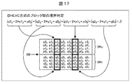
![]()
![]()
なお、図18に示されるように、p2i、p1i、p0iの画素値に傾きがある場合、従来のR2W2による複写(Padding)においては、p2iの画素値は参照できない。したがって、p2iの画素値の代わりに、ハッチングの丸に示されるように、直下のp1iの画素値が複写(Padding)して用いられるが、実際のp2iの画素値は、点線の丸の位置であるので、誤差が生じてしまう。 As shown in FIG. 18, when the pixel values of p2 i , p1 i , and p0 i are inclined, the pixel value of p2 i cannot be referred to in the conventional copying (padding) by R2W2. Therefore, instead of the pixel value of p2 i, the pixel value of p1 i immediately below is used as a padding as shown by the hatched circle, but the actual pixel value of p2 i is the dotted circle. Because of this position, an error occurs.
これに対して、本技術のR2W2による一次線形予測においては、p2iの画素値は参照できないので、p2iの画素値は、ハッチングの丸に示されるように、p1iおよびp0iの画素値に傾きから一次線形により予測された画素値(=実際と同じ画素値)が用いられる。 In contrast, in the R2W2 by the primary linear prediction of the present technology, since the pixel value of p2 i are not available, the pixel value of p2 i, as shown in circles hatching, the pixel values of p1 i and p0 i The pixel value (= the same pixel value as the actual value) predicted from the slope by the first-order linearity is used.
以上のようにすることで、画素値に傾きがある場合においては、本技術によれば、従来の複写(Padding)の方法よりも誤差が生じることがない。したがって、R2W2であっても、デブロッキングのブロックノイズリダクションの機能を保ちつつ、ラインメモリの削減を実現することができる。 As described above, in the case where the pixel value has an inclination, according to the present technology, an error does not occur as compared with the conventional copying method. Therefore, even with R2W2, it is possible to reduce the line memory while maintaining the deblocking block noise reduction function.
また、例えば4K×2Kの画像における1ラインは、2K×1Kの画像の2ライン分に相当する。また、H.264/AVC方式では、4ライン分のラインメモリを備えており、4K ×2Kの画像における1ライン分のメモリ容量は、H.264/AVC方式の50%のメモリ容量に相当する。すなわち、高解像度画像においてメモリ容量の削減効果が高くなる。 For example, one line in a 4K × 2K image corresponds to two lines in a 2K × 1K image. H. The H.264 / AVC system includes a line memory for four lines, and the memory capacity for one line in a 4K × 2K image is H.264. This corresponds to a memory capacity of 50% of the H.264 / AVC format. That is, the effect of reducing the memory capacity is increased in a high resolution image.
なお、p2i、p1i、p0iの画素値に傾きがない場合には、実質的に、直下のp1iの画素値が用いられることと同等となる。この場合も、R2W2であっても、デブロッキングのブロックノイズリダクションの機能を保ちつつ、ラインメモリの削減を実現することができる。 In addition, when there is no inclination in the pixel values of p2 i , p1 i , and p0 i , this is substantially equivalent to using the pixel value of p1 i immediately below. In this case as well, even with R2W2, it is possible to reduce the line memory while maintaining the deblocking block noise reduction function.
[R2W2の場合のフィルタ処理]
次に、R2W2の場合の輝度信号のフィルタ処理について説明する。R2は、参照される画素を示し、W2は、フィルタ処理が適用される画素を示す。すなわち、R2W2とは、図19に示されるように、LCUのライン境界上の2画素を参照して、LCUのライン境界上の2画素にフィルタ処理が適用されることを表す。
[Filter processing for R2W2]
Next, the luminance signal filter processing in the case of R2W2 will be described. R2 indicates a pixel to be referred to, and W2 indicates a pixel to which filter processing is applied. That is, as shown in FIG. 19, R2W2 refers to two pixels on the LCU line boundary being referred to and filtering processing applied to the two pixels on the LCU line boundary.
なお、図19の例においては、図16におけるブロックBKu内のライン境界BBから上に3列目と4列目の画素が参照できないことが明示されている。 In the example of FIG. 19, it is clearly indicated that the pixels in the third and fourth columns cannot be referred to above the line boundary BB in the block BKu in FIG.
比較として再度示すが、HEVC方式における輝度信号の強フィルタリングでは、式(50)乃至式(55)の演算を行うことで、フィルタ処理範囲の各画素の輝度成分が算出される。なお、式(50)乃至式(55)は、式(37)乃至式(42)にそれぞれ対応する式である。 As shown again for comparison, in the strong filtering of the luminance signal in the HEVC method, the luminance component of each pixel in the filter processing range is calculated by performing the calculations of Expressions (50) to (55). Expressions (50) to (55) are expressions corresponding to Expressions (37) to (42), respectively.
これに対して、本技術のR2W2の場合の輝度信号の強フィルタリングでは、式(56)乃至式(60)の演算を行うことで、フィルタ処理範囲の各画素の輝度成分が算出される。 On the other hand, in the strong filtering of the luminance signal in the case of R2W2 according to the present technology, the luminance component of each pixel in the filter processing range is calculated by performing the calculations of Expressions (56) to (60).
ここで、R2W2の場合の強フィルタリングの式(56)は、線形近似の式(49)により、HEVC方式における強フィルタリングの式(50)の「p2i+2*p1i+2*p0i」が「4*p1i+p0i」に入れ替わっている点が異なっている。 Here, the strong filtering equation (56) in the case of R2W2 is obtained by replacing the linear filtering equation (49) with “p2 i + 2 * p1 i + 2 * p0 i ” of the strong filtering equation (50) in the HEVC scheme. 4 * p1 i + p0 i ”is different.
R2W2の場合の強フィルタリングの式(58)は、線形近似の式(49)により、HEVC方式における強フィルタリングの式(52)の「p2i+p1i+p0i」が「3*p1i」に入れ替わっている点が異なっている。 In the strong filtering equation (58) in the case of R2W2, “p2 i + p1 i + p0 i ” in the strong filtering equation (52) in the HEVC scheme is replaced with “3 * p1 i ” by the linear approximation equation (49). Is different.
R2W2の場合の強フィルタリングにおいては、HEVC方式における強フィルタリングの式(54)に対応する式が削除されている点が異なっている。 The strong filtering in the case of R2W2 is different in that the expression corresponding to the strong filtering expression (54) in the HEVC scheme is deleted.
すなわち、本技術のR2W2の場合においては、ブロックBkuのライン境界BBから上に3行目の行の画素「p2i」が参照されないので、代わりに、線形近似の式(49)が代入して用いられる。 That is, in the case of R2W2 of the present technology, since the pixel “p2 i ” in the third row is not referred to from the line boundary BB of the block Bku, the linear approximation formula (49) is substituted instead. Used.
また、ブロックBkuのライン境界BBから上に3行目の行の画素「p20」には、フィルタ処理が施されないので、R2W2の場合の強フィルタリングにおいては、HEVC方式における強フィルタリングの式(54)に対応する式が削除される。 Also, since the pixel “p2 0 ” in the third row above the line boundary BB of the block Bku is not subjected to the filtering process, in the strong filtering in the case of R2W2, the strong filtering formula (54 ) Is deleted.
次に、ライン境界における輝度信号の弱フィルタリングの判定式と弱フィルタリングについて説明する。 Next, a determination formula for weak filtering of the luminance signal at the line boundary and weak filtering will be described.
まず、HEVC方式における輝度信号の弱フィルタリングの判定式と弱フィルタリングでは、式(61)乃至式(63)の演算を行うことで、フィルタ処理範囲の各画素の輝度成分が算出される。なお、式(61)乃至式(63)における第1式目が、弱フィルタリングの判定式である。 First, in the weak signal determination method and weak filtering of the luminance signal in the HEVC method, the luminance component of each pixel in the filter processing range is calculated by performing the operations of Equations (61) to (63). Note that the first expression in the expressions (61) to (63) is a weak filtering determination expression.
これに対して、R2W2の場合の輝度信号の弱フィルタリングの判定式と弱フィルタリングでは、式(64)乃至式(66)の演算を行うことで、フィルタ処理範囲の各画素の輝度成分が算出される。なお、式(64)乃至式(66)における第1式目が、弱フィルタリングの判定式である。 On the other hand, in the luminance signal weak filtering determination expression and weak filtering in the case of R2W2, the luminance component of each pixel in the filter processing range is calculated by performing the calculations of Expressions (64) to (66). The Note that the first expression in the expressions (64) to (66) is a weak filtering determination expression.
ここで、R2W2の場合の式(65)のうち、弱フィルタリングの式である第2式目のtc2のクリップ内は、線形近似の式(49)により、HEVC方式における式(62)のうち、第2式目のtc2のクリップ内と異なっている。すなわち、第2式目のtc2のクリップ内は、HEVC方式の第2式目のtc2のクリップ内「((((p2i+p0i+1)>>1)−p1i+delta)>>1)」が、「((((p1i+p1i+1)>>1)−p1i+delta)>>1)」に入れ替わっている。 Here, in the expression (65) in the case of R2W2, the inside of the clip of the second expression tc2 which is the weak filtering expression is expressed by the linear approximation expression (49), among the expressions (62) in the HEVC method. It differs from the clip of tc2 in the second formula. That is, the clip of tc2 in the second expression is included in the clip of tc2 in the second expression of the HEVC system “((((p2 i + p0 i +1) >> 1) −p1 i + delta) >> 1)”. Is replaced by “((((p1 i + p1 i +1) >> 1) −p1 i + delta) >> 1)”.
また、R2W2の場合の式(65)のうち、弱フィルタリングの判定式である第1式目のif文内は、HEVC方式における式(62)のうち、第1式目のif文内と異なっている。すなわち、第1式目のif文内は、HEVC方式の第1式目のif文内「abs(p22−2*p12+p02)+abs(p25−2*p15+p05)」が、「abs(0−(p12−p02))+abs(0−(p15−p05))」に入れ替わっている。 Further, in the expression (65) in the case of R2W2, the inside of the first expression if sentence, which is a weak filtering judgment expression, is different from the expression in the HEVC system (62) in the first expression if sentence. ing. That is, in the if statement of the first expression, the “ifs (p2 2 −2 * p1 2 + p0 2 ) + abs (p2 5 −2 * p1 5 + p0 5 )” in the if statement of the first expression of the HEVC method is included. , “Abs (0− (p1 2 −p0 2 )) + abs (0− (p1 5 −p0 5 ))”.
すなわち、式(65)のうち、第1式目については、線形近似ではなく、次の式(67)に示される、直下の画素での複写(padding)が行われる。換言するに、「abs(0−(p12−p02))」における0は、「0=p22−p12」を表しており、「abs(0−(p15−p05))」における0は、「0=p25−p15」を表している。 In other words, the first expression in the expression (65) is not linearly approximated, and is copied (padding) at the pixel immediately below, as shown in the following expression (67). In other words, 0 in “abs (0− (p1 2 −p0 2 ))” represents “0 = p2 2 −p1 2 ” and “abs (0− (p1 5 −p0 5 ))”. 0 in the symbol represents “0 = p2 5 −p1 5 ”.
![]()
これは、フィルタリングの判定式における傾きについての判定に関して、線形近似を用いると、実際にはスルーできないものについての判定までスルーしてしまうためである。したがって、弱フィルタリングの判定式における傾きの判定については、式(67)に示されるように、直下の画素での複写(padding)が行われるものとする。これは、次に述べる強フィルタリングの判定式やブロック間の境界判定式についても同じことがいえる。
![]()
This is because, with respect to the determination regarding the slope in the filtering determination formula, if linear approximation is used, the determination regarding what cannot be actually passed is passed. Accordingly, regarding the determination of the slope in the weak filtering determination formula, it is assumed that copying (padding) is performed at the pixel immediately below as shown in the formula (67). The same can be said for the strong filtering judgment formula and the boundary judgment formula between blocks described below.
次に、ライン境界における輝度信号のブロック間の境界判定式と強フィルタリングの判定式について説明する。 Next, a boundary determination formula between blocks of luminance signals at a line boundary and a determination formula for strong filtering will be described.
まず、HEVC方式における輝度信号のブロック間の境界判定式は、次の式(68)で表わされ、強フィルタリングの判定式は、次の式(69)で表わされる。
これに対して、本技術のR2W2の場合のブロック間の境界判定式は、次の式(70)で表わされ、強フィルタリングの判定式は、次の式(71)で表わされる。
R2W2の場合のブロック間の境界判定の式(70)のif文内の第1項目および第2項目は、複写(padding)の式(67)により、HEVC方式におけるブロック間の境界判定の式(68)のif文内の第1項目および第2項目と異なっている。すなわち、if文内の第1項目と第2項目は、HEVC方式のif文内の第1項目と第2項目「abs(p22−2*p12+p02)+abs(p25−2*p15+p05)」が、「abs(0−(p12−p02))+abs(0−(p15−p05))」に入れ替わっている。 The first item and the second item in the “if” sentence of the boundary determination formula (70) of the block in the case of R2W2 are expressed by the formula (67) of the boundary between blocks in the HEVC method (padding formula (67)). 68) is different from the first item and the second item in the if sentence. That is, the first item and the second item in the if sentence are the first item and the second item “abs (p2 2 −2 * p1 2 + p0 2 ) + abs (p2 5 −2 * p1) in the HEVC system if sentence. 5 + p0 5 ) ”is replaced with“ abs (0− (p1 2 −p0 2 )) + abs (0− (p1 5 −p0 5 )) ”.
また、R2W2の場合の強フィルタリング判定の式(71)の1行目の絶対値内が、複写(padding)の式(67)により、HEVC方式における強フィルタリング判定の式(69)の1行目の絶対値内と異なっている。すなわち、式(71)の1行目の絶対値内は、式(69)の1行目の絶対値内「abs(p22−2*p12+p02)+abs(p25−2*p15+p05)」が、「abs(0−(p12−p02))+abs(0−(p15−p05))」に入れ替わっている。 Further, the absolute value of the first row of the strong filtering determination formula (71) in the case of R2W2 is the first row of the strong filtering determination formula (69) in the HEVC method by the padding formula (67). It is different from the absolute value of. That is, the absolute value in the first row of the equation (71) is within the absolute value in the first row of the equation (69) “abs (p2 2 −2 * p1 2 + p0 2 ) + abs (p2 5 −2 * p1 5 + p0 5) "has replaced the" abs (0- (p1 2 -p0 2 )) + abs (0- (p1 5 -p0 5)) ".
さらに、R2W2の場合の強フィルタリング判定の式(71)の1つ目の「and」以降の式が、HEVC方式における強フィルタリング判定の式(69)の1つ目の「and」以降の式と異なっている。すなわち、式(71)の1つ目の「and」以降の式は、式(69)の1つ目の「and」以降の式「(|p3i−p0i<<1|+|q0i−q3i|)」<(β>>3))」が、「(|p1i−p0i<<1|+|q0i−q3i|)」<(β>>3))」に入れ替わっている。 Further, the expression after the first “and” of the strong filtering determination expression (71) in the case of R2W2 is the following expression after the first “and” of the strong filtering determination expression (69) in the HEVC scheme. Is different. That is, the expression after the first “and” in the expression (71) is the expression “(| p3 i −p0 i << 1 | + | q0 i after the first“ and ”in the expression (69). −q3 i |) ”<(β >> 3))” is replaced with “(| p1 i −p0 i << 1 | + | q0 i −q3 i |)” <(β >> 3)) ” ing.
なお、この部分の判定は、画素値の大きさの判定であるので、線形近似の式(49)および複写(padding)の式(67)が用いられている。すなわち、式(71)の1つ目の「and」以降の式は、式(69)1つ目の「and」以降の式において、まず、「p3i」が、複写により「p2i」に近似されて、その後、「p2i」が、線形により「2*p1i−p0i」に近似されて生成されている。 Since the determination of this part is the determination of the size of the pixel value, the linear approximation formula (49) and the copying formula (67) are used. That is, the first expression after “and” in the expression (71) is the same as the expression after the first “and” in the expression (69). First, “p3 i ” is changed to “p2 i ” by copying. After that, “p2 i ” is generated by being approximated to “2 * p1 i −p0 i ” linearly.
[R2W1の場合のフィルタ処理]
次に、R2W1の場合の輝度信号のフィルタ処理について説明する。R2は、参照される画素を示し、W1は、フィルタ処理が適用される画素を示す。すなわち、R2W1とは、図19に示されるように、LCUのライン境界上の2画素を参照して、LCUのライン境界上の1画素にフィルタ処理が適用されることを表す。
[Filter processing for R2W1]
Next, the luminance signal filter processing in the case of R2W1 will be described. R2 indicates a pixel to be referred to, and W1 indicates a pixel to which filter processing is applied. That is, as shown in FIG. 19, R2W1 refers to the fact that the filtering process is applied to one pixel on the LCU line boundary with reference to two pixels on the LCU line boundary.
R2W1の場合の本技術の輝度信号の強フィルタリングでは、式(72)乃至式(75)の演算を行うことで、フィルタ処理範囲の各画素の輝度成分が算出される。 In the strong filtering of the luminance signal of the present technology in the case of R2W1, the luminance component of each pixel in the filter processing range is calculated by performing the calculations of Expressions (72) to (75).
ここで、R2W1の場合の強フィルタリングの式(72)は、線形近似の式(49)により、HEVC方式における強フィルタリングの式(50)の「p2i+2*p1i+2*p0i」が「4*p1i+p0i」に入れ替わっている点が異なっている。 Here, the strong filtering equation (72) in the case of R2W1 is expressed by the linear approximation equation (49), where “p2 i + 2 * p1 i + 2 * p0 i ” of the strong filtering equation (50) in the HEVC scheme is “ 4 * p1 i + p0 i ”is different.
R2W1の場合の強フィルタリングにおいては、HEVC方式における強フィルタリングの式(52)および式(54)に対応する式が削除されている点が異なっている。 The strong filtering in the case of R2W1 is different in that the expressions corresponding to the strong filtering expressions (52) and (54) in the HEVC scheme are deleted.
すなわち、本技術においては、ブロックBkuのライン境界BBから上に3行目の行の画素「p2i」が参照されないので、代わりに、線形近似の式(49)が代入して用いられる。 That is, in the present technology, since the pixel “p2 i ” in the third row is not referred to above the line boundary BB of the block Bku, the linear approximation formula (49) is used instead.
また、ブロックBkuのライン境界BBから上に2行目の行の画素「p10」および3行目の行の画素「p20」には、フィルタ処理が施されない。したがって、R2W1の場合の強フィルタリングにおいては、HEVC方式における強フィルタリングの式(52)および式(54)に対応する式が削除される。 Further, the pixel “p1 0 ” in the second row and the pixel “p2 0 ” in the third row above the line boundary BB of the block Bku are not filtered. Therefore, in the strong filtering in the case of R2W1, the expressions corresponding to the strong filtering expressions (52) and (54) in the HEVC scheme are deleted.
次に、ライン境界における輝度信号の弱フィルタリングの判定式と弱フィルタリングについて説明する。 Next, a determination formula for weak filtering of the luminance signal at the line boundary and weak filtering will be described.
R2W1の場合の輝度信号の弱フィルタリングの判定式と弱フィルタリングでは、式(76)および式(77)の演算を行うことで、フィルタ処理範囲の各画素の輝度成分が算出される。 In the weak signal determination formula and weak filtering of the luminance signal in the case of R2W1, the luminance component of each pixel in the filter processing range is calculated by performing the calculation of Expression (76) and Expression (77).
ここで、R2W1の場合、ブロックBkuのライン境界BBから上に2行目の行の画素「p10」には、フィルタ処理が施されない。したがって、R2W1の場合の弱フィルタリングの判定式と弱フィルタリングにおいては、HEVC方式における式(62)に対応する式が削除される。 Here, in the case of R2W1, the pixel “p1 0 ” in the second row above the line boundary BB of the block Bku is not filtered. Therefore, in the weak filtering determination formula and weak filtering in the case of R2W1, the formula corresponding to formula (62) in the HEVC scheme is deleted.
次に、ライン境界における輝度信号のブロック間の境界判定式と強フィルタリングの判定式について説明する。 Next, a boundary determination formula between blocks of luminance signals at a line boundary and a determination formula for strong filtering will be described.
R2W1の場合のブロック間の境界判定式は、次の式(78)で表わされ、強フィルタリングの判定式は、次の式(79)で表わされる。
R2W1の場合のブロック間の境界判定の式(78)のif文内の第1項目および第2項目は、複写(padding)の式(67)により、HEVC方式におけるブロック間の境界判定の式(68)のif文内の第1項目および第2項目と異なっている。すなわち、if文内の第1項目と第2項目は、HEVC方式のif文内の第1項目と第2項目「abs(p22−2*p12+p02)+abs(p25−2*p15+p05)」が、「abs(0−(p12−p02))+abs(0−(p15−p05))」に入れ替わっている。 In the case of R2W1, the first item and the second item in the if statement of the boundary determination equation (78) between blocks are expressed by the equation (67) for the boundary determination between blocks in the HEVC method (padding equation (67)). 68) is different from the first item and the second item in the if sentence. That is, the first item and the second item in the if sentence are the first item and the second item “abs (p2 2 −2 * p1 2 + p0 2 ) + abs (p2 5 −2 * p1) in the HEVC system if sentence. 5 + p0 5 ) ”is replaced with“ abs (0− (p1 2 −p0 2 )) + abs (0− (p1 5 −p0 5 )) ”.
また、R2W1の場合の強フィルタリング判定の式(79)の1行目の絶対値内が、複写(padding)の式(67)により、HEVC方式における強フィルタリング判定の式(69)の1行目の絶対値内と異なっている。すなわち、式(79)の1行目の絶対値内は、式(69)の1行目の絶対値内「abs(p22−2*p12+p02)+abs(p25−2*p15+p05)」が、「abs(0−(p12−p02))+abs(0−(p15−p05))」に入れ替わっている。 Further, the absolute value of the first row of the strong filtering determination formula (79) in the case of R2W1 is the first row of the strong filtering determination formula (69) in the HEVC scheme by the padding formula (67). It is different from the absolute value of. That is, the absolute value in the first row of the formula (79) is within the absolute value of the first row of the formula (69) “abs (p2 2 −2 * p1 2 + p0 2 ) + abs (p2 5 −2 * p1 5 + p0 5) "has replaced the" abs (0- (p1 2 -p0 2 )) + abs (0- (p1 5 -p0 5)) ".
さらに、R2W1の場合の強フィルタリング判定の式(79)の1つ目の「and」以降の式が、HEVC方式における強フィルタリング判定の式(69)の1つ目の「and」以降の式と異なっている。すなわち、式(79)の1つ目の「and」以降の式は、式(69)1つ目の「and」以降の式「(|p3i−p0i<<1|+|q0i−q3i|)」<(β>>3))」が、「(|p1i−p0i<<1|+|q0i−q3i|)」<(β>>3))」に入れ替わっている。 Further, the expression after the first “and” of the strong filtering determination expression (79) in the case of R2W1 is the expression after the first “and” of the strong filtering determination expression (69) in the HEVC scheme. Is different. That is, the expression after the first “and” in the expression (79) is the expression “(| p3 i −p0 i << 1 | + | q0 i − after the first“ and ”in the expression (69). q3 i |) ”<(β >> 3))” is replaced with “(| p1 i −p0 i << 1 | + | q0 i −q3 i |)” <(β >> 3)) ” Yes.
R2W2の場合に上述したように、この部分の判定は、画素値の大きさの判定であるので、線形近似の式(49)および複写(padding)の式(67)が用いられている。すなわち、式(79)の1つ目の「and」以降の式は、式(69)1つ目の「and」以降の式にいおいて、まず、「p3i」が「p2i」に近似されて、その後、「p2i」が「2*p1i−p0i」に近似されて生成されている。 As described above in the case of R2W2, since the determination of this portion is the determination of the size of the pixel value, the linear approximation formula (49) and the copying formula (67) are used. That is, the first expression after “and” in Expression (79) is the same as that in Expression (69) after the first “and”. First, “p3 i ” is changed to “p2 i ”. Then, “p2 i ” is approximated to “2 * p1 i −p0 i ” and generated.
なお、以上の線形近似による判定処理を実現するための構成例と動作については、デブロッキングフィルタ処理部の第6および第7の実施の形態として、後述する図22乃至図24を参照して説明する。 The configuration example and the operation for realizing the determination process based on the above linear approximation will be described as sixth and seventh embodiments of the deblocking filter processing unit with reference to FIGS. 22 to 24 described later. To do.
なお、上述したように、本技術においては、ライン境界におけるブロック間の境界判定と強フィルタリング判定式を、線形近似の式(49)および複写(padding)の式(67)を用いて変更している。このため、上記判定式を誤ってスルーし、誤ってデブロッキングフィルタ処理が行われてしまった場合の対応として、強フィルタリング処理にクリップ処理を追加する。 As described above, in the present technology, the boundary determination between blocks at the line boundary and the strong filtering determination formula are changed using the linear approximation formula (49) and the copying formula (67). Yes. For this reason, a clip process is added to the strong filtering process as a response to the case where the determination formula is mistakenly passed and the deblocking filter process is erroneously performed.
[本技術の説明(強フィルタリングにおけるクリップ処理)]
次に、第8の実施の形態である強フィルタリングにおけるクリップ処理について説明する。R2W2の場合の輝度信号の強フィルタリングは、クリップ処理が追加された、次の式(80)乃至式(84)を用いることも可能である。
Next, clip processing in strong filtering according to the eighth embodiment will be described. For the strong filtering of the luminance signal in the case of R2W2, the following equations (80) to (84) to which clipping processing is added can be used.
強フィルタリングの式(80)は、フィルタリング後のp00の算出式である。強フィルタリングの式(80)においては、式(56)における0乃至255のクリップ処理内と、p00との差分に対して(-tc)乃至tcのクリップ処理が施された値が、p00に加算されたものに対して、0乃至255によるクリップ処理が行われている。 The strong filtering expression (80) is an expression for calculating p0 0 after filtering. In the strong filtering expression (80), the value obtained by performing the clipping process of (−tc) to tc on the difference between the clipping process of 0 to 255 and the difference of p0 0 in the expression (56) is p0 0. A clip process from 0 to 255 is performed on the value added to.
強フィルタリングの式(81)は、フィルタリング後のq00の算出式である。強フィルタリングの式(81)においては、式(57)における0乃至255のクリップ処理内と、q00との差分に対して(-tc)乃至tcのクリップ処理が施された値が、q00に加算されたものに対して、0乃至255によるクリップ処理が行われている。 The strong filtering expression (81) is an expression for calculating q0 0 after filtering. In the strong filtering equation (81), the value obtained by performing the clipping processing of (−tc) to tc on the difference between the clipping processing of 0 to 255 and the difference of q0 0 in the equation (57) is q0 0. A clip process from 0 to 255 is performed on the value added to.
強フィルタリングの式(82)は、フィルタリング後のp10の算出式である。強フィルタリングの式(82)においては、式(58)における0乃至255のクリップ処理内と、p10との差分に対して(-tc)乃至tcのクリップ処理が施された値が、p10に加算されたものに対して、0乃至255によるクリップ処理が行われている。 Strong filtering expression (82) is a calculation formula of p1 0 after filtering. In strong filtering of formula (82), and the clipping of 0 to 255 in formula (58), the value clipping of (-tc) to tc relative difference is applied between the p1 0 is, p1 0 A clip process from 0 to 255 is performed on the value added to.
強フィルタリングの式(83)は、フィルタリング後のq10の算出式である。強フィルタリングの式(83)においては、式(59)における0乃至255のクリップ処理内と、q10との差分に対して(-tc)乃至tcのクリップ処理が施された値が、q10に加算されたものに対して、0乃至255によるクリップ処理が行われている。 Strong filtering expression (83) is a calculation formula for q1 0 after filtering. In strong filtering of formula (83), and the clipping of 0 to 255 in formula (59), the value clipping of (-tc) to tc relative difference is applied between q1 0 is, q1 0 A clip process from 0 to 255 is performed on the value added to.
強フィルタリングの式(84)は、フィルタリング後のq20の算出式である。強フィルタリングの式(84)においては、式(60)における0乃至255のクリップ処理内と、q20との差分に対して(-tc)乃至tcのクリップ処理が施された値が、q20に加算されたものに対して、0乃至255によるクリップ処理が行われている。 Strong filtering expression (84) is a calculation formula of q2 0 after filtering. In the strong filtering expression (84), the value obtained by performing the clipping process of (−tc) to tc on the difference between the clipping process of 0 to 255 and the difference of q2 0 in the expression (60) is q2 0. A clip process from 0 to 255 is performed on the value added to.
以上のようにすることで、過度なフィルタ処理がかかるのを抑制することが可能である。 By doing as described above, it is possible to suppress an excessive filtering process.
なお、ここで、Matthias Narroschke, Tomas Wedi, Semih Esenlik, “Results for modified decisions for deblocking”, JCTVC-G590, Joint Collaborative Team on Video Coding (JCT-VC) of ITU-T SG16 WP3 and ISO/IEC JTC1/SC29/WG11 7th Meeting, Geneva, CH, 21-30 November, 2011(以下、非特許文献2と称する)が提案されている。 Here, Matthias Narroschke, Tomas Wedi, Semih Esenlik, “Results for modified decisions for deblocking”, JCTVC-G590, Joint Collaborative Team on Video Coding (JCT-VC) of ITU-T SG16 WP3 and ISO / IEC JTC1 / SC29 / WG11 7th Meeting, Geneva, CH, 21-30 November, 2011 (hereinafter referred to as Non-Patent Document 2) has been proposed.
非特許文献2においては、ブロック単位で強フィルタリング・弱フィルタリングの判定処理が記載されている。しかしながら、非特許文献2に記載の判定処理では、注目ラインとそのラインが含まれるブロック単位の判定が異なる場合(注目ラインは弱フィルタリングの判定であるのに対して,それを含むブロックは強フィルタリング判定で、注目ラインに強フィルタリングが適用される場合)、過度なフィルタ処理がかかる。
また、非特許文献2においては、強フィルタリング、弱フィルタリングの判定処理が4ライン単位で行われるため、判定とフィルタリング処理との間でミスマッチが起こる。ミスマッチの例としては、強と判定される必要があるのに、弱フィルタが行われたり、弱と判定される必要があるのに、強フィルタが行われたりする。
Further, in
なお、HEVC方式(HM-5.0)における輝度信号の強フィルタリングでは、次の式(85)乃至式(89)が採用されている。
本技術では、判定処理のミスマッチ及び判定処理の不完全さを解消するために、次の式(90)乃至式(94)で示すクリップ処理を適用することも可能である。なお、式(90)においては、フィルタ処理によって変化する部分Δ値にクリップ処理を行いたいので、p0iがクリップ処理の外に出されている。他の式(91)乃至式(94)についても同様である。
また、tcは、量子化パラメータQPに応じて変動する。よって、クリップ値におけるtcにかかる倍数もQPが大きくなると大きくなる(すなわち、QPに応じて変動する)ようにすることも可能である。このクリップ処理にかかるパラメータ(クリップ値やクリップ値におけるtcにかかる倍数の値)は、予め設定されていてもよいし、符号化ストリームに付加して、復号側へ伝送することも可能である。 Also, tc varies according to the quantization parameter QP. Therefore, the multiple of tc in the clip value can also be increased as QP increases (that is, it varies according to QP). A parameter related to the clip processing (a clip value or a multiple of tc in the clip value) may be set in advance, or may be added to the encoded stream and transmitted to the decoding side.
なお、上述した式(90)乃至式(94)は、次の式(95)乃至式(99)のようにクリップ処理を行うようにしてもよい。
ここで、上述したHEVC方式(HM-5.0)における輝度信号の強フィルタリングの式(85)乃至式(89)は、ライン境界における輝度信号の強フィルタリングの式である。すなわち、HEVC方式(HM-5.0)において、輝度信号の強フィルタリングは、実際には、次の式(100)乃至式(105)で表わされている。
これらの式(100)乃至式(105)に対応して、本技術では、判定処理のミスマッチ及び判定処理の不完全さを解消するために、輝度信号の強フィルタリングに、次の式(106)乃至式(111)で示すように、クリップ処理を適用することが可能である。なお、式(106)の第1式においては、上述した式(90)乃至(94)の例と同様に、フィルタ処理によって変化する部分Δ値にクリップ処理を行いたいので、p0iがクリップ処理の外に出されている。他の式(107)乃至式(111)の第1式についても同様である。 Corresponding to these formulas (100) to (105), in the present technology, in order to eliminate the mismatch of the determination process and the incompleteness of the determination process, the following expression (106) is used for the strong filtering of the luminance signal. As shown by the formula (111), it is possible to apply clip processing. Note that in the first expression of Expression (106), as in the examples of Expressions (90) to (94) described above, since it is desired to perform the clipping process on the partial Δ value that changes by the filter process, p0 i is the clip process. Has been put out of. The same applies to the first expressions of the other expressions (107) to (111).
p0i = p0i + Clip(-pv)-(pv)((p2i + 2*p1i - 6*p0i +2*q0i + q1i + 4)>>3); i=0,7
= Clip(p0i -pv)-(p0i +pv)((p2i + 2*p1i + 2*p0i +2*q0i + q1i + 4)>>3); ・・・(106)
q0i = q0i + Clip(-pv)-(pv)((p1i + 2*p0i - 6*q0i + 2*q1i + q2i + 4)>>3); i=0,7
= Clip(q0i -pv)-(q0i +pv)((p1i + 2*p0i + 2*q0i + 2*q1i + q2i + 4)>>3); ・・・(107)
p1i = p1i + Clip(-pv)-(pv)((p2i - 3*p1i + p0i + q0i +2)>>2); i=0,7
= Clip(p1i -pv)-(p1i +pv)((p2i + p1i + p0i + q0i +2)>>2); ・・・(108)
q1i = q1i + Clip(-pv)-(pv)((p0i + q0i - 3*q1i + q2i +2)>>2); i=0,7
= Clip(q1i -pv)-(q1i +pv)((p0i + q0i + q1i + q2i +2)>>2); ・・・(109)
p2i = p2i + Clip(-pv)-(pv)((2*p3i - 5*p2i + p1i + p0i + q0i + 4)>>3); i=0,7
= Clip(p2i -pv)-(p2i +pv)((2*p3i + 3*p2i + p1i + p0i + q0i + 4)>>3); ・・・(110)
q2i = q2i + Clip(-pv)-(pv)((p0i + q0i + q1i - 5*q2i + 2*q3i + 4)>>3); i=0,7
= Clip(q2i -pv)-(q2i +pv)((p0i + q0i + q1i + 3*q2i + 2*q3i + 4)>>3); ・・・(111)
ここで、クリップ値pvは、パラメータtcの1倍、2倍、3倍、4倍、5倍、6倍、7倍、8倍のいずれかとする。すなわち、pv=tc,2*tc,3*tc,4*tc,5*tc,6*tc,7*tc,8*tcである。なお、クリップ値pvは、パラメータtcの2倍が好適と考えられるが、1乃至8倍のいずれかでよいと想定される。また、同等の効果が得られれば、1乃至8倍には限定されない。
p0i = p0i + Clip (-pv)-(pv) ((p2i + 2 * p1i-6 * p0i + 2 * q0i + q1i + 4) >>3); i = 0,7
= Clip (p0i -pv)-(p0i + pv) ((p2i + 2 * p1i + 2 * p0i + 2 * q0i + q1i + 4) >>3); (106)
q0i = q0i + Clip (-pv)-(pv) ((p1i + 2 * p0i-6 * q0i + 2 * q1i + q2i + 4) >>3); i = 0,7
= Clip (q0i -pv)-(q0i + pv) ((p1i + 2 * p0i + 2 * q0i + 2 * q1i + q2i + 4) >>3); (107)
p1i = p1i + Clip (-pv)-(pv) ((p2i-3 * p1i + p0i + q0i +2) >>2); i = 0,7
= Clip (p1i -pv)-(p1i + pv) ((p2i + p1i + p0i + q0i +2) >>2); (108)
q1i = q1i + Clip (-pv)-(pv) ((p0i + q0i-3 * q1i + q2i +2) >>2); i = 0,7
= Clip (q1i -pv)-(q1i + pv) ((p0i + q0i + q1i + q2i +2) >>2); (109)
p2i = p2i + Clip (-pv)-(pv) ((2 * p3i-5 * p2i + p1i + p0i + q0i + 4) >>3); i = 0,7
= Clip (p2i -pv)-(p2i + pv) ((2 * p3i + 3 * p2i + p1i + p0i + q0i + 4) >>3); (110)
q2i = q2i + Clip (-pv)-(pv) ((p0i + q0i + q1i-5 * q2i + 2 * q3i + 4) >>3); i = 0,7
= Clip (q2i -pv)-(q2i + pv) ((p0i + q0i + q1i + 3 * q2i + 2 * q3i + 4) >>3); (111)
Here, the clip value pv is any one of the parameter tc of 1, 2, 3, 4, 5, 6, 6, 7, or 8. That is, pv = tc, 2 * tc, 3 * tc, 4 * tc, 5 * tc, 6 * tc, 7 * tc, 8 * tc. The clip value pv is considered to be preferably twice the parameter tc, but is assumed to be any one of 1 to 8 times. Moreover, if an equivalent effect is acquired, it will not be limited to 1 to 8 times.
また、tcは、量子化パラメータQPに応じて変動する。よって、クリップ値におけるtcにかかる倍数もQPが大きくなると大きくなる(すなわち、QPに応じて変動する)ようにすることも可能である。このクリップ処理にかかるパラメータ(クリップ値やクリップ値におけるtcにかかる倍数の値)は、予め設定されていてもよいし、符号化ストリームに付加して、復号側へ伝送することも可能である。 Also, tc varies according to the quantization parameter QP. Therefore, the multiple of tc in the clip value can also be increased as QP increases (that is, it varies according to QP). A parameter related to the clip processing (a clip value or a multiple of tc in the clip value) may be set in advance, or may be added to the encoded stream and transmitted to the decoding side.
図20は、実験による、上述した式(100)乃至式(105)のHEVC方式(HM-5.0)における輝度信号の強フィルタリングによって変化する画素値の最大値を示す図である。 FIG. 20 is a diagram illustrating the maximum value of the pixel value that is changed by strong filtering of the luminance signal in the HEVC method (HM-5.0) of the above-described formulas (100) to (105) based on the experiment.
AI_HE、RA_HE、LB_HE、およびLP_HEは、本実験のコンディションを示している。AI_HE は、実験がALL INTRA High Efficiencyで行われたことを表している。RA_HE は、実験がRandom Access High Efficiencyで行われたことを表している。LB_HEは、実験がLow Delay B High Efficiencyで行われたことを表している。LP_HEは、実験がLow Delay P High Efficiencyで行われたことを表している。 AI_HE, RA_HE, LB_HE, and LP_HE indicate the condition of this experiment. AI_HE indicates that the experiment was performed at ALL INTRA High Efficiency. RA_HE indicates that the experiment was performed with Random Access High Efficiency. LB_HE represents that the experiment was performed with Low Delay B High Efficiency. LP_HE indicates that the experiment was performed with Low Delay P High Efficiency.
AI_HE、RA_HE、LB_HE、およびLP_HEの下に示される「22、27、32、37」は、実験に用いられた量子化パラメータの値である。また、Class A乃至Class Fは、実験に用いられたテストシーケンスの種類を示している。 “22, 27, 32, 37” shown below AI_HE, RA_HE, LB_HE, and LP_HE are values of quantization parameters used in the experiment. Class A to Class F indicate the types of test sequences used in the experiment.
図20に示されるように、HEVC方式(HM-5.0)における輝度信号の強フィルタリングによって変化する画素値は、すなわち、クリップ処理がない場合に強フィルタリングによって変化する画素値は、場合によっては100以上大きく変化してしまう。 As shown in FIG. 20, the pixel value that changes due to the strong filtering of the luminance signal in the HEVC method (HM-5.0), that is, the pixel value that changes due to the strong filtering when there is no clipping processing, is 100 or more in some cases. It will change greatly.
そこで、輝度信号の強フィルタリングにクリップ処理を適用する。これにより、次の図21に示されるように、判定処理のミスマッチ及び判定処理の不完全さの影響を最小限に抑えることができる。 Therefore, clip processing is applied to strong filtering of luminance signals. As a result, as shown in FIG. 21 below, it is possible to minimize the influence of the mismatch of the determination process and the incompleteness of the determination process.
図21の例においては、実線で示されるエッジ(ブロック境界ではない)がある場合で、本来はデブロッキング処理を行いたくないが、非特許文献2の技術により、デブロッキング処理が施されてしまうと、点線に示されるように画素値が大きく変化してしまう。
In the example of FIG. 21, when there is an edge (not a block boundary) indicated by a solid line, the deblocking process is originally performed but the deblocking process is performed by the technique of
例えば、デブロッキング処理前には、実線で示されるように、画素p2i、画素p1i、および画素p0iの値は、255であり、画素q0i、画素q1i、および画素q2iの値は、0であり、画素p0iおよび画素q0iの値の差Dは、255である。 For example, before the deblocking process, as indicated by solid lines, the values of the pixel p2 i , the pixel p1 i , and the pixel p0 i are 255, and the values of the pixel q0 i , the pixel q1 i , and the pixel q2 i Is 0, and the difference D between the values of the pixels p0 i and q0 i is 255.
これに対して、点線で示されるように、デブロッキング処理後の画素p2iの値は223となり、画素p1iの値は、191となり、画素p0iの値は、159となり、画素p2i、画素p1i、および画素p0iの画素値が大きく変化してしまっていた。また、デブロッキング処理後の画素q0iの値は、96となり、画素q1iの値は、64となり、画素q2iの値は、32となり、画素q0i、画素q1i、および画素q2iの画素値が大きく変化してしまっていた。 On the other hand, as indicated by the dotted line, the value of the pixel p2 i after the deblocking process is 223, the value of the pixel p1 i is 191 and the value of the pixel p0 i is 159, and the pixel p2 i , The pixel values of the pixel p1 i and the pixel p0 i have changed greatly. In addition, the value of the pixel q0 i after the deblocking process is 96, the value of the pixel q1 i is 64, the value of the pixel q2 i is 32, and the values of the pixels q0 i , q1 i , and q2 i The pixel value has changed greatly.
このような場合に、例えば、上述した式(106)乃至式(111)の強フィルタリングにおいて、クリップ値が10のクリップ処理を行う。 In such a case, for example, clip processing with a clip value of 10 is performed in the above-described strong filtering of Expressions (106) to (111).
これにより、太線で示されるように、デブロッキング後、画素p2i、画素p1i、および画素p0iの値は、245となり、画素q0i、画素q1i、および画素q2iの値は、255となり、上述した画素値の変化を最小限に抑えることができる。 As a result, as indicated by the bold line, after deblocking, the values of the pixel p2 i , the pixel p1 i , and the pixel p0 i are 245, and the values of the pixel q0 i , the pixel q1 i , and the pixel q2 i are 255 Thus, the above-described change in pixel value can be minimized.
なお、以上の強フィルタリングにおけるクリップ処理を実現するための構成例と動作については、デブロッキングフィルタ処理部の第8の実施の形態として、後述する図25乃至図27を参照して説明する。 A configuration example and operation for realizing the clipping processing in the above strong filtering will be described as an eighth embodiment of the deblocking filter processing unit with reference to FIGS. 25 to 27 described later.
<13.デブロッキングフィルタ処理部の第6の実施の形態>
[デブロッキングフィルタ処理部の構成例]
図22は、デブロッキングフィルタ処理部の第6の実施の形態の構成を例示している。デブロッキングフィルタ処理部24は、画像メモリ71、ブロック境界判定部72−1、フィルタ強度判定部73−1、フィルタ演算部74−1、セレクタ75、係数メモリ76、および制御部77を含むように構成される。デブロッキングフィルタ処理部24は、さらに、ライン境界ブロック境界判定部72−2、ライン境界フィルタ強度判定部73−2、およびライン境界フィルタ演算部74−2を含むように構成されている。
<13. Sixth Embodiment of Deblocking Filter Processing Unit>
[Configuration Example of Deblocking Filter Processing Unit]
FIG. 22 illustrates the configuration of the sixth embodiment of the deblocking filter processing unit. The deblocking
画像メモリ71は、図9のラインメモリ241に相当する部であり、ラインメモリで構成されている。画像メモリ71は、加算部23から供給された画像データを記憶する。画像メモリ71は、記憶している画像データを読み出して、ブロック境界判定部72−1、フィルタ強度判定部73−1、およびフィルタ演算部74−1に供給する。画像メモリ71は、また、記憶している画像データを読み出して、ライン境界ブロック境界判定部72−2、ライン境界フィルタ強度判定部73−2、およびライン境界フィルタ演算部74−2にも供給する。
The
なお、ライン境界ではないところでは、画像メモリ71に画像データは記憶されず、加算部23から供給された画像データが各部に供給されて、それが処理される場合もある。しかしながら、図22の例においては、説明の便宜上、画像メモリ71を経由した画像データが処理されるとして説明する。
It should be noted that there is a case where the image data is not stored in the
ブロック境界判定部72−1は、制御部77の制御のもと、ブロック間の境界判定を行う。すなわち、ブロック境界判定部72−1は、画像メモリ71から読み出された画像データを用いて上述のブロック間の境界判定処理をブロック毎に行い、フィルタ処理を行うブロック間の境界を検出する。ブロック境界判定部72−1は、検出結果をフィルタ強度判定部73−1に出力する。
The block boundary determination unit 72-1 performs boundary determination between blocks under the control of the
フィルタ強度判定部73−1は、制御部77の制御のもと、上述のようにフィルタ強度の判定を行う。すなわち、フィルタ強度判定部73−1は、画像メモリ71からの、ブロックの境界を挟んで隣接する2つのブロックの画像データを用いて、ライン毎に、強フィルタリングまたは弱フィルタリングの何れの強度でフィルタ処理を行うか判定して、判定結果をフィルタ演算部74−1に出力する。
The filter strength determination unit 73-1 determines the filter strength as described above under the control of the
フィルタ演算部74−1は、制御部77の制御のもと、画像メモリ71に記憶されている画像データ、および係数メモリ76から読み出したフィルタ係数を用いて、ライン毎に、フィルタ強度判定部73−1で判定されたフィルタ強度でフィルタ演算を行う。フィルタ演算部74−1は、フィルタ処理がなされた画像データをセレクタ75に出力する。
The filter calculation unit 74-1 uses the image data stored in the
ライン境界ブロック境界判定部72−2は、制御部77の制御のもと、LCUのライン境界である場合に、ブロック間の境界判定を行う。すなわち、ライン境界ブロック境界判定部72−2は、画像メモリ71から読み出された画像データを用いて上述のブロック間の境界判定処理をブロック毎に行い、フィルタ処理を行うブロック間の境界を検出する。ライン境界ブロック境界判定部72−2は、検出結果をライン境界フィルタ強度判定部73−2に出力する。
The line boundary block boundary determination unit 72-2 performs boundary determination between blocks when the line boundary of the LCU is under the control of the
ライン境界フィルタ強度判定部73−2は、制御部77の制御のもと、LCUのライン境界である場合に、上述のようにフィルタ強度の判定を行う。すなわち、ライン境界フィルタ強度判定部73−2は、画像メモリ71からの、ブロックの境界を挟んで隣接する2つのブロックの画像データを用いて、ライン毎に、強フィルタリングまたは弱フィルタリングの何れの強度でフィルタ処理を行うか判定して、判定結果をライン境界フィルタ演算部74−2に出力する。
The line boundary filter strength determination unit 73-2 determines the filter strength as described above when the line boundary of the LCU is under the control of the
ライン境界フィルタ演算部74−2は、制御部77の制御のもと、画像メモリ71に記憶されている画像データ、および係数メモリ76から読み出したフィルタ係数を用いて、ライン毎に、ライン境界フィルタ強度判定部73−2で判定されたフィルタ強度でフィルタ演算を行う。ライン境界フィルタ演算部74−2は、フィルタ処理がなされた画像データをセレクタ75に出力する。
The line boundary filter calculation unit 74-2 uses the image data stored in the
セレクタ75は、制御部77の制御のもと、フィルタ演算部74−1からの画像データまたはライン境界フィルタ演算部74−2からの画像データのどちらかを選択して、選択した画像データを、フレームメモリ25に出力する。
The
係数メモリ76は、デブロッキングフィルタ処理のフィルタ演算に用いるフィルタ係数を記憶している。係数メモリ76は、記憶しているフィルタ係数を読み出し、フィルタ演算部74−1およびライン境界フィルタ演算部74−2に供給する。 The coefficient memory 76 stores filter coefficients used for the filter operation of the deblocking filter process. The coefficient memory 76 reads out the stored filter coefficients and supplies them to the filter calculation unit 74-1 and the line boundary filter calculation unit 74-2.
制御部77は、デブロッキングフィルタ処理部24の各部を制御する。制御部77は、例えば、画像メモリ71を制御して、ブロック内の下端側の所定ライン数分の画像データを記憶させ、記憶されている画像データの読み出しを行う。制御部77は、LCU内ライン判定部77Aを含むように構成されている。
The
LCU内ライン判定部77Aは、ラスタースキャン方向に順次処理が行われるブロック単位に、例えばLCU間のライン境界であるか判定して判定結果を、ブロック境界判定部72−1、フィルタ強度判定部73−1、およびフィルタ演算部74−1に供給し、ライン境界ではない場合に、処理を行わせる。また、LCU内ライン判定部77Aは、その判定結果を、ライン境界ブロック境界判定部72−2、ライン境界フィルタ強度判定部73−2、およびライン境界フィルタ演算部74−2にも供給し、ライン境界であった場合に、処理を行わせる。さらに、LCU内ライン判定部77Aは、その判定結果を、セレクタ75に供給し、ライン境界であった場合、ライン境界フィルタ演算部74−2からの画像データを選択させ、ライン境界ではない場合、フィルタ演算部74−1からの画像データを選択させる。
The intra-LCU
なお、図22のデブロッキングフィルタ処理部24においては、例えば、R2W2処理を行うことが予め設定されていてもよいし、図9の例と同様に、フィルタ処理範囲やフィルタ演算範囲を制御することができるように構成してもよい。
In the deblocking
[デブロッキングフィルタ処理部の動作]
次に、図23のフローチャートを参照して、図22のデブロッキングフィルタ処理部24のデブロッキング処理について説明する。なお、図23の例においては、R2W2の処理が行われる場合について説明する。
[Operation of Deblocking Filter Processing Unit]
Next, the deblocking process of the deblocking
ステップS91において、LCU内ライン判定部77Aは、ラスタースキャン方向に順次処理が行われるブロック単位に、かけるフィルタが、LCU境界の垂直フィルタであるか否かを判定する。すなわち、ステップS91においては、LCU間のライン境界であって、かけるフィルタが垂直フィルタであるか否かが判定される。
In step S91, the in-LCU
ステップS91において、かけるフィルタが、LCU境界の垂直フィルタであると判定された場合、処理は、ステップS92に進む。ステップS92において、ライン境界ブロック境界判定部72−2は、制御部77の制御のもと、LCUのライン境界である場合に、ライン境界のブロック間の境界判定を行う。
If it is determined in step S91 that the filter to be applied is a vertical filter at the LCU boundary, the process proceeds to step S92. In step S <b> 92, the line boundary block boundary determination unit 72-2 performs boundary determination between the blocks of the line boundary under the control of the
すなわち、ライン境界ブロック境界判定部72−2は、画像メモリ71から読み出された画像データを用いて、上述した式(70)により、ブロック間の境界判定処理をブロック毎に行い、フィルタ処理を行うブロック間の境界を検出する。ライン境界ブロック境界判定部72−2は、検出結果をライン境界フィルタ強度判定部73−2に出力する。
That is, the line boundary block boundary determination unit 72-2 uses the image data read from the
ステップS93において、ライン境界フィルタ強度判定部73−2は、制御部77の制御のもと、LCUのライン境界である場合に、上述のように、ライン境界のフィルタ強度の判定を行う。
In step S93, under the control of the
すなわち、ライン境界フィルタ強度判定部73−2は、画像メモリ71からの、ブロックの境界を挟んで隣接する2つのブロックの画像データを用いて、強フィルタリングまたは弱フィルタリングの何れの強度でフィルタ処理を行うか判定する。なお、上述した式(71)により強フィルタリングの判定が行われる。また、上述した式(64)乃至式(66)の第1式目により、弱フィルタリングの判定が行われる。ライン境界フィルタ強度判定部73−2は、判定結果をライン境界フィルタ演算部74−2に出力する。
That is, the line boundary filter strength determination unit 73-2 uses the image data of two blocks adjacent to each other across the block boundary from the
ステップS94において、ライン境界フィルタ演算部74−2は、制御部77の制御のもと、ライン境界のフィルタ処理を行う。すなわち、ライン境界フィルタ演算部74−2は、画像メモリ71に記憶されている画像データ、および係数メモリ76から読み出したフィルタ係数を用いて、ライン境界フィルタ強度判定部73−2で判定されたフィルタ強度でフィルタ演算を行う。
In step S94, the line boundary filter calculation unit 74-2 performs line boundary filtering under the control of the
強フィルタリングの場合、上述した式(56)乃至式(60)によりフィルタ演算が行われる。また、弱フィルタリングの場合、上述した式(64)乃至式(66)の第2式目および第3式目によりフィルタ演算が行われる。ライン境界フィルタ演算部74−2は、フィルタ処理がなされた画像データをセレクタ75に出力する。
In the case of strong filtering, the filter operation is performed according to the above-described equations (56) to (60). In the case of weak filtering, the filter operation is performed by the second and third expressions of the above-described expressions (64) to (66). The line boundary filter calculation unit 74-2 outputs the image data subjected to the filter process to the
LCU内ライン判定部77Aは、ステップS95において、処理対象のラインが、LCUにおける最後の8ライン目であるか否かを判定する。ステップS95において、処理対象のラインが、LCUにおける最後の8ライン目ではないと判定された場合、処理は、ステップS93に戻り、それ以降の処理が繰り返される。
In step S95, the in-LCU
また、ステップS95において、処理対象のラインが、LCUにおける最後の8ライン目であると判定された場合、処理は、ステップS100に進む。 If it is determined in step S95 that the processing target line is the last 8th line in the LCU, the process proceeds to step S100.
一方、ステップS91において、かけるフィルタが、LCU境界の垂直フィルタではないと判定された場合、処理は、ステップS96に進む。ステップS96において、ブロック境界判定部72−1は、制御部77の制御のもと、ブロック間の境界判定を行う。
On the other hand, if it is determined in step S91 that the filter to be applied is not the vertical filter at the LCU boundary, the process proceeds to step S96. In step S <b> 96, the block boundary determination unit 72-1 performs boundary determination between blocks under the control of the
すなわち、ブロック境界判定部72−1は、画像メモリ71から読み出された画像データを用いて、上述した式(68)により、ブロック間の境界判定処理をブロック毎に行い、フィルタ処理を行うブロック間の境界を検出する。ブロック境界判定部72−1は、検出結果をフィルタ強度判定部73−1に出力する。
That is, the block boundary determination unit 72-1 uses the image data read from the
フィルタ強度判定部73−1は、ステップS97において、制御部77の制御のもと、上述のようにフィルタ強度の判定を行う。すなわち、フィルタ強度判定部73−1は、画像メモリ71からの、ブロックの境界を挟んで隣接する2つのブロックの画像データを用いて、ライン毎に、強フィルタリングまたは弱フィルタリングの何れの強度でフィルタ処理を行うか判定する。なお、上述した式(69)により強フィルタリングの判定が行われる。また、上述した式(61)乃至式(63)の第1式目により、弱フィルタリングの判定が行われる。フィルタ強度判定部73−1は、判定結果をフィルタ演算部74−1に出力する。
In step S97, the filter strength determination unit 73-1 determines the filter strength as described above under the control of the
フィルタ演算部74−1は、ステップS98において、制御部77の制御のもと、ブロック境界のフィルタ演算を行う。すなわち、フィルタ演算部74−1は、画像メモリ71に記憶されている画像データ、および係数メモリ76から読み出したフィルタ係数を用いて、ライン毎に、フィルタ強度判定部73−1で判定されたフィルタ強度でフィルタ演算を行う。
In step S98, the filter calculation unit 74-1 performs a filter calculation of the block boundary under the control of the
強フィルタリングの場合、上述した式(50)乃至式(55)によりフィルタ演算が行われる。また、弱フィルタリングの場合、上述した式(61)乃至式(63)の第2式目および第3式目によりフィルタ演算が行われる。フィルタ演算部74−1は、フィルタ処理がなされた画像データをセレクタ75に出力する。
In the case of strong filtering, the filter operation is performed according to the above-described equations (50) to (55). In the case of weak filtering, the filter operation is performed by the second and third expressions of the above-described expressions (61) to (63). The filter calculation unit 74-1 outputs the image data subjected to the filter process to the
LCU内ライン判定部77Aは、ステップS99において、処理対象のラインが、LCUにおける最後の8ライン目であるか否かを判定する。ステップS99において、処理対象のラインが、LCUにおける最後の8ライン目ではないと判定された場合、処理は、ステップS97に戻り、それ以降の処理が繰り返される。
In step S99, the intra-LCU
また、ステップS99において、処理対象のラインが、LCUにおける最後の8ライン目であると判定された場合、処理は、ステップS100に進む。 If it is determined in step S99 that the processing target line is the last 8th line in the LCU, the process proceeds to step S100.
ステップS100において、LCU内ライン判定部77Aは、画像の最後のブロックであるか否かを判定する。すなわち、ステップS100においては、画面内の再度のブロックのライン境界であるかが判定される。
In step S100, the in-LCU
ステップS100において、画像の最後のブロックであると判定された場合、デブロッキング処理は終了する。ステップS100において、画像の最後のブロックではないと判定された場合、処理は、ステップS91に戻り、ラスタースキャン順に次のLCUについてそれ以降の処理が繰り返される。 If it is determined in step S100 that the block is the last block of the image, the deblocking process ends. If it is determined in step S100 that the block is not the last block of the image, the process returns to step S91, and the subsequent processes are repeated for the next LCU in the raster scan order.
なお、図22の例においては、フィルタ演算部74−1においてライン境界以外の場合の係数を用い、ライン境界フィルタ演算部74−2においてライン境界の場合の係数を用いて、どちらを用いるかが、LCU内ライン判定部77Aにおいて選択される。これにより、ライン境界におけるフィルタ処理とライン境界以外のフィルタ処理を切り替えるようにする例を説明した。
In the example of FIG. 22, the filter calculation unit 74-1 uses a coefficient other than the line boundary, and the line boundary filter calculation unit 74-2 uses the coefficient in the case of the line boundary. Are selected by the in-LCU
これに対して、用いる係数を1つにして、読み出す画素のアドレスを制御することで、ライン境界におけるフィルタ処理とライン境界以外のフィルタ処理を切り替えるようにすることも可能である。 On the other hand, it is also possible to switch between the filter processing at the line boundary and the filter processing other than the line boundary by controlling the address of the pixel to be read out by using one coefficient.
例えば、R2W2の強フィルタリングにおけるP00の算出を例に説明する。HEVC方式における強フィルタリングの式(50)において、
p(ブロックBKu)にかかる項は、「p2i+2*P1i+2*q0i」となっている。
For example, the calculation of P0 0 in R2W2 strong filtering will be described as an example. In the expression (50) of strong filtering in the HEVC method,
The term concerning p (block BKu) is “p2 i + 2 * P1 i + 2 * q0 i ”.
一方、HEVC方式における強フィルタリングの式(56)においては、
p(ブロックBKu)にかかる項は、「4*P1i+q0i」となっている。
On the other hand, in the strong filtering formula (56) in the HEVC scheme,
The term relating to p (block BKu) is “4 * P1 i + q0 i ”.
ここで、 4*P1i+q0i = q0i + 2*P1i+ 2*P1iである。 Here, 4 * P1 i + q0 i = q0 i + 2 * P1 i + 2 * P1 i .
すなわち、式(50)におけるpにかかる項も、式(56)におけるpにかかる項も、係数は、左から、1、2、2が用いられている。したがって、同じ係数を用いて、その係数の乗算対象の画素値を入れ替える(読み出すアドレスを変更する)だけで、ライン境界におけるフィルタ処理とライン境界以外のフィルタ処理を切り替えるようにすることが可能である。
That is, as for the term concerning p in the formula (50) and the term concerning p in the formula (56),
<14.デブロッキングフィルタ処理部の第7の実施の形態>
[デブロッキングフィルタ処理部の構成例]
図24は、デブロッキングフィルタ処理部の第7の実施の形態の構成を示している。
<14. Seventh Embodiment of Deblocking Filter Processing Unit>
[Configuration Example of Deblocking Filter Processing Unit]
FIG. 24 shows the configuration of the seventh embodiment of the deblocking filter processing unit.
図24の例において、デブロッキングフィルタ処理部24は、画像メモリ71、ブロック境界判定部72、フィルタ強度判定部73、フィルタ演算部74、係数メモリ76、および制御部77を含むように構成されている。
In the example of FIG. 24, the deblocking
なお、図24のデブロッキングフィルタ処理部24は、画像メモリ71、係数メモリ76、制御部77は、図22のデブロッキングフィルタ処理部24と共通している。
Note that the deblocking
図24のデブロッキングフィルタ処理部24は、ブロック境界判定部72−1とライン境界ブロック境界判定部72−2とがまとめて、ブロック境界判定部72に入れ替わった点が、図22のデブロッキングフィルタ処理部24と異なっている。図24のデブロッキングフィルタ処理部24は、フィルタ強度判定部73−1とライン境界フィルタ強度判定部73−2とがまとめて、フィルタ強度判定部73に入れ替わった点が、図22のデブロッキングフィルタ処理部24と異なっている。図24のデブロッキングフィルタ処理部24は、フィルタ演算部74−1とライン境界フィルタ演算部74−2とがまとめて、フィルタ演算部74に入れ替わった点が、図22のデブロッキングフィルタ処理部24と異なっている。
The deblocking
さらに、図24のデブロッキングフィルタ処理部24は、制御部77のLCU内ライン判定部77Aが、LCU内ライン判定部77Bと入れ替わった点が、図22のデブロッキングフィルタ処理部24と異なっている。
Further, the deblocking
すなわち、LCU内ライン判定部77Bは、R2W2の強フィルタリングにおけるP00の算出を例に、上述したように、画像メモリ71から読み出される画素のアドレスを制御する。したがって、画像メモリ71は、LCU内ライン判定部77Bによる制御に基づいて、画素を読み出し、読み出した画素を、ブロック境界判定部72、フィルタ強度判定部73、フィルタ演算部74に供給する。
That is, the in-LCU
ブロック境界判定部72は、ブロック間の境界判定を行う。すなわち、ブロック境界判定部72は、画像メモリ71から読み出された画像データを用いて上述のブロック間の境界判定処理をブロック毎に行い、フィルタ処理を行うブロック間の境界を検出する。ブロック境界判定部72は、検出結果をフィルタ強度判定部73に出力する。
The block
フィルタ強度判定部73は、上述のようにフィルタ強度の判定を行う。すなわち、フィルタ強度判定部73は、画像メモリ71からの、ブロックの境界を挟んで隣接する2つのブロックの画像データを用いて、ライン毎に、強フィルタリングまたは弱フィルタリングの何れの強度でフィルタ処理を行うか判定して、判定結果をフィルタ演算部74に出力する。
The filter
フィルタ演算部74は、画像メモリ71に記憶されている画像データ、および係数メモリ76から読み出したフィルタ係数を用いて、ライン毎に、フィルタ強度判定部73で判定されたフィルタ強度でフィルタ演算を行う。フィルタ演算部74は、フィルタ処理がなされた画像データをフレームメモリ25に出力する。
The
なお、図24のデブロッキングフィルタ処理部24によるデブロッキングフィルタ処理は、図23を参照して上述したデブロッキングフィルタ処理と基本的に同様の処理であるので、その説明は省略される。
The deblocking filter processing by the deblocking
以上のように、フィルタ演算に用いる画像範囲が狭くなったことにより参照できなくなった画素について、ブロックの境界判定における波形の傾きを用いて補間するようにした。これにより、画素値間に傾きがある場合のデブロッキング処理について、LCUのライン境界において画像範囲を狭くしても行えるようになる。 As described above, the pixels that cannot be referred to due to the narrowed image range used for the filter calculation are interpolated using the slope of the waveform in the block boundary determination. As a result, the deblocking process when there is an inclination between the pixel values can be performed even if the image range is narrowed at the line boundary of the LCU.
また、フィルタ演算に用いる画像範囲が狭くなったことにより参照できなくなった画素について、ブロックの境界判定、並びに強弱フィルタの判定においては、ブロックの境界判定における波形の傾きとPaddingを用いて補間するようにした。これにより、画素値間に傾きがある場合のデブロッキングの判定処理について、LCUのライン境界において画像範囲を狭くしても、行えるようになる。 In addition, for pixels that cannot be referenced because the image range used for the filter operation has become narrower, interpolation is performed using the slope of the waveform and padding in the block boundary determination and the determination of the strength filter. I made it. This makes it possible to perform deblocking determination processing when there is an inclination between pixel values even if the image range is narrowed at the LCU line boundary.
以上により、LCUのライン境界においては、画像範囲を狭くしても、デブロッキングの処理の機能を保ちつつ、ラインメモリの削減を実現することが可能である。 As described above, at the LCU line boundary, even if the image range is narrowed, it is possible to reduce the line memory while maintaining the function of the deblocking process.
<15.デブロッキングフィルタ処理部の第8の実施の形態>
[デブロッキングフィルタ処理部の構成例]
図25は、デブロッキングフィルタ処理部の第8の実施の形態の構成を示している。
<15. Eighth Embodiment of Deblocking Filter Processing Unit>
[Configuration Example of Deblocking Filter Processing Unit]
FIG. 25 illustrates the configuration of the eighth embodiment of the deblocking filter processing unit.
図25の例において、デブロッキングフィルタ処理部24は、画像メモリ81、ブロック境界判定部82、フィルタ強度判定部83、フィルタ演算部84、係数メモリ85、および制御部86を含むように構成されている。
In the example of FIG. 25, the deblocking
画像メモリ81は、図22の画像メモリ71に相当する部であり、ラインメモリで構成されている。画像メモリ81は、加算部23から供給された画像データを記憶する。画像メモリ81は、記憶している画像データを読み出して、ブロック境界判定部82、フィルタ強度判定部83、およびフィルタ演算部84に供給する。
The
なお、ライン境界ではないところでは、画像メモリ81に画像データは記憶されず、加算部23から供給された画像データが各部に供給されて、それが処理される場合もある。しかしながら、図25の例においては、説明の便宜上、画像メモリ81を経由した画像データが処理されるとして説明する。
It should be noted that there is a case where the image data is not stored in the
ブロック境界判定部82は、制御部86の制御のもと、8ライン毎に、境界を導出し、判定に用いるパラメータを算出したりして、4ライン毎に、ブロック間の境界判定を行う。すなわち、ブロック境界判定部82は、画像メモリ81から読み出された画像データを用いて、TUおよびPUの境界を導出し、BS値を導出する。さらに、ブロック境界判定部82は、処理対象の境界に隣接する2つの領域の量子化パラメータQPの平均を求めて、平均QP(量子化パラメータ)を算出し、算出した平均QPに基づいて、パラメータtcおよびβを算出する。
Under the control of the
そして、ブロック境界判定部82は、画像メモリ81からの、ブロックの境界を挟んで隣接する2つのブロックの画像データと、算出したパラメータを用いて、4ライン毎に、フィルタを行うかどうかを判定する。ブロック境界判定部82は、ブロック境界判定部82は、境界判定結果とともに、算出したパラメータを、フィルタ強度判定部83に供給する。
Then, the block
フィルタ強度判定部83は、制御部86の制御のもと、4ライン毎に、フィルタ強度の判定を行う。すなわち、フィルタ強度判定部83は、ブロック境界判定部82によりフィルタを行うと判定された場合、強フィルタリングまたは弱フィルタリングの何れの強度でフィルタ処理を行うか判定して、判定結果をフィルタ演算部84に出力する。
The filter
フィルタ演算部84は、制御部86の制御のもと、画像メモリ81に記憶されている画像データ、および係数メモリ85から読み出したフィルタ係数を用いて、4ライン毎に、フィルタ強度判定部83で判定されたフィルタ強度でフィルタ演算を行う。特に、フィルタ強度判定部83により強フィルタを行うと判定された場合、フィルタ演算部84は、上述した式(106)乃至式(111)を用いて、クリップ処理付きの強フィルタ処理を行う。フィルタ演算部84は、フィルタ処理がなされた画像データを後段のフレームメモリ25に出力する。
The
係数メモリ85は、デブロッキングフィルタ処理のフィルタ演算に用いるフィルタ係数を記憶している。係数メモリ85は、記憶しているフィルタ係数を読み出し、フィルタ演算部84に供給する。
The
制御部86は、図示せぬ操作部(復号側の場合、可逆復号部52)から情報(デブロッキングフィルタのON/OFF情報、パラメータβ、tcの各オフセット値、およびクリップ処理にかかるパラメータなど)を入力する。また、制御部86には、予測モード情報や量子化パラメータなどデブロッキングフィルタに必要なパラメータも供給される。
The
例えば、制御部86は、入力される情報を、対応する部に供給したり、入力されるON/OFF情報に基づいて、デブロッキングフィルタ処理部24の各部を制御する。
For example, the
制御部86は、例えば、画像メモリ81を制御して、ブロック内の下端側の所定ライン数分の画像データを記憶させ、記憶されている画像データの読み出しを行う。また、制御部86は、フィルタ演算部84を制御し、強フィルタを行う場合に、クリップ処理付き強フィルタ処理を行わせる。その際、制御部86は、このクリップ処理にかかるパラメータ(例えば、クリップ値pvやクリップ値におけるtcの倍数値)をフィルタ演算部84に供給する。
For example, the
[デブロッキングフィルタ処理部の動作]
次に、図26のフローチャートを参照して、図25のデブロッキングフィルタ処理部24のデブロッキング処理について説明する。
[Operation of Deblocking Filter Processing Unit]
Next, the deblocking process of the deblocking
例えば、図示せぬ操作部(復号側の場合、可逆復号部52)を介してON/OFF情報、βオフセットの値、およびTcオフセットの値、クリップ処理にかかるパラメータが制御部86に入力される。また、制御部86には、予測モード情報や量子化パラメータなどデブロッキングフィルタに必要なパラメータも供給される。
For example, ON / OFF information, β offset value, Tc offset value, and parameters related to clip processing are input to the
ステップS201において、制御部86は、フィルタのオフセット(βオフセットおよびTcオフセット)を設定し、設定したオフセットの情報を、フィルタ強度判定部83に供給する。
In step S <b> 201, the
ステップS202において、制御部86は、ON/OFF情報に基づいて、デブロッキングフィルタが利用不可であるか否かを判定する。ステップS202において、デブロッキングフィルタが利用不可であると判定した場合、デブロッキングフィルタ処理は終了される。
In step S202, the
ステップS202において、デブロッキングフィルタが利用不可ではないと判定された場合、制御部86は、ブロック境界判定部82、フィルタ強度判定部83、およびフィルタ演算部84に、その旨を通知し、処理は、ステップS203に進む。その際、各部に必要なパラメータなども制御部86から供給される。
When it is determined in step S202 that the deblocking filter is not usable, the
ステップS203において、ブロック境界判定部82は、8ライン単位で、TUとPUの境界を導出する。ステップS204において、ブロック境界判定部82は、ステップS203で導出したTUとPUの境界などの情報や、制御部86からの予測モード情報などを基に、BS(Boundary Strength)値の導出を行う。
In step S203, the block
ステップS205において、ブロック境界判定部82、フィルタ強度判定部83、およびフィルタ演算部84は、輝度境界のフィルタ処理を行う。この輝度境界のフィルタ処理は、次の図27を参照して後述するが、ステップS205の処理により、輝度信号に対して、輝度境界のフィルタが施される。
In step S205, the block
ステップS206において、ブロック境界判定部82、フィルタ強度判定部83、およびフィルタ演算部84は、色差境界のフィルタ処理を行う。ステップS206の処理により、色差信号に対して、色差境界のフィルタが施される。
In step S206, the block
ステップS207において、制御部86は、全部の境界を処理したか否かを判定する。ステップS207において、全部の境界を処理していないと判定された場合、処理は、ステップS205に戻り、それ以降の処理が繰り返される。ステップS207において、全部の境界を処理したと判定された場合、処理は、ステップS208に進む。
In step S207, the
ステップS208において、制御部86は、全部のCUを処理したか否かを判定する。ステップS208において、まだ全部のCUを処理していないと判定された場合、処理は、ステップS203に戻り、それ以降の処理が繰り返される。
In step S208, the
ステップS208において、全部のCUを処理したと判定された場合、デブロッキングフィルタ処理は終了される。 If it is determined in step S208 that all CUs have been processed, the deblocking filter process is terminated.
[輝度境界のフィルタ処理の例]
次に、図27のフローチャートを参照して、図26のステップS205における輝度境界のフィルタ処理について説明する。
[Example of luminance boundary filtering]
Next, the luminance boundary filtering process in step S205 in FIG. 26 will be described with reference to the flowchart in FIG.
ブロック境界判定部82は、ステップS231において、8ライン単位で、BS値が0より大きいか否かを判定する。ステップS231において、BS値が0より大きくはないと判定された場合、輝度境界のフィルタ処理は終了する。すなわち、この場合の輝度境界には、フィルタ演算部84によるフィルタ処理は施されず、フィルタ前の画素値がそのまま出力される。
In step S231, the block
ステップS231において、BS値が0より大きいと判定された場合、処理は、ステップS232に進む。ステップS232において、ブロック境界判定部82は、8ライン単位で、画像メモリ81からの画素値を用いて、処理対象の境界に隣接する2つの領域の量子化パラメータQPの平均を求めて、平均QP(量子化パラメータ)を算出する。このときの量子化パラメータQPは、制御部86から供給される。
If it is determined in step S231 that the BS value is greater than 0, the process proceeds to step S232. In step S232, the block
ステップS233において、ブロック境界判定部82は、8ライン単位で、ステップS232により算出された平均QPに基づいて、パラメータtcおよびβを算出する。
In step S233, the block
ステップS234において、ブロック境界判定部82は、4ライン単位のフィルタのon/off判定を行う。すなわち、ブロック境界判定部82は、算出したパラメータβなどを用いて、4ライン単位のフィルタのon/off判定を行う。この判定処理には、例えば、例えば、上述した式(68)が用いられる。
In step S234, the block
ステップS234におけるon/off判定結果は、境界判定結果として、算出したパラメータと一緒に、フィルタ強度判定部83に供給される。
The on / off determination result in step S234 is supplied to the filter
また、ステップS235において、フィルタ強度判定部83は、4ライン単位のフィルタ強度判定を行う。すなわち、フィルタ強度判定部83は、ブロック境界判定部82により算出されたパラメータβやパラメータtcなどを用いて、4ライン単位のフィルタ強度判定を行う。この判定処理には、例えば、上述した式(69)や式(61)乃至式(63)における第1式目が用いられる。
In step S235, the filter
ステップS234におけるon/off判定結果およびステップS235におけるフィルタ強度判定結果は、フィルタ演算部84に供給される。なお、このとき、パラメータtcもフィルタ演算部84に供給される。
The on / off determination result in step S234 and the filter strength determination result in step S235 are supplied to the
ステップS236において、フィルタ演算部84は、フィルタ強度判定部83からの判定結果に基づいて、処理対象の4ラインに対して、強フィルタを適用するか否かを判定する。ステップS236において、処理対象の4ラインに対して、強フィルタを適用すると判定された場合、処理は、ステップS237に進む。
In step S <b> 236, the
ステップS237において、フィルタ演算部84は、制御部86による制御のもと、上述した式(106)乃至式(111)を用いて、クリップ処理付き強フィルタ処理を行う。フィルタ演算部84は、フィルタ処理後の画素値を、後段に出力する。
In step S237, the
ステップS236において、強フィルタを適用しないと判定された場合、ステップS238において、フィルタ演算部84は、フィルタ強度判定部83からの判定結果に基づいて、処理対象の4ラインに対して、弱フィルタを適用するか否かを判定する。ステップS238において、弱フィルタを適用すると判定された場合、処理は、ステップ239に進む。
If it is determined in step S236 that the strong filter is not applied, in step S238, the
ステップS239において、フィルタ演算部84は、弱フィルタ処理を行う。フィルタ演算部84は、フィルタ処理後の画素値を、後段に出力する。
In step S239, the
ステップS238において、弱フィルタを適用しないと判定された場合、処理は、ステップ240に進む。ステップS240において、フィルタ演算部84は、フィルタ強度判定部83からの判定結果に基づいて、処理対象の4ラインに対して、処理を施さず、そのまま、フィルタ処理後の画素値を、後段に出力する。
If it is determined in step S238 that the weak filter is not applied, the process proceeds to step 240. In step S240, based on the determination result from the filter
ステップS240において、フィルタ演算部84は、8ラインの処理が完了したか否かを判定し、8ラインの処理が完了したと判定した場合、輝度信号のデブロッキングを終了する。ステップS240において、8ラインの処理がまだ完了していないと判定された場合、処理は、ステップS234に戻り、それ以降の処理が繰り返される。
In step S240, the
以上のように、強フィルタを適用すると判定された場合に、クリップ処理付きの強フィルタリングを行うようにしたので、判定処理のミスマッチ及び判定処理の不完全さの影響を最小限に抑えることができる。これにより、デブロッキング処理において、適切にフィルタリングがかかるようにすることができる。 As described above, when the strong filter is determined to be applied, the strong filtering with the clip process is performed, so that the influence of the mismatch of the determination process and the imperfection of the determination process can be minimized. . Thereby, filtering can be appropriately applied in the deblocking process.
なお、上記説明においては、線形近似およびクリップ処理付き強フィルタリングについて説明した。そして、線形近似の説明においては、例として、R2W2およびR2W1の場合について説明したが、R3W2、R1W1の場合も同様の方法で線形近似の処理を行うことが可能である。 In the above description, linear approximation and strong filtering with clip processing have been described. In the description of the linear approximation, the case of R2W2 and R2W1 has been described as an example, but the case of R3W2 and R1W1 can also perform the linear approximation process by the same method.
<16.第9の実施の形態>
[R3W2の例]
次に、図28を参照して、R3W2の例の場合について説明する。図28の例においては、実線上の白丸がデブロックフィルタ前の、図16に示された境界BB付近のp2i,p1i,p0i,q0i,q1i,q2iの各画素値を表している。図28に示されるように、ブロックBKuとブロックBKlの段差(ギャップ)は、D=p0i−q0iである。
<16. Ninth Embodiment>
[Example of R3W2]
Next, the case of the example of R3W2 will be described with reference to FIG. In the example of FIG. 28, the white circles on the solid line indicate the pixel values of p2 i , p1 i , p0 i , q0 i , q1 i , q2 i near the boundary BB shown in FIG. 16 before the deblocking filter. Represents. As shown in FIG. 28, the step (gap) between the block BKu and the block BKl is D = p0 i −q0 i .
また、点線上の丸は、HEVC方式における輝度信号の強フィルタリング後の各画素値を表している。すなわち、この場合、フィルタ前の画素値と強フィルタリング後の画素値の差は、q2iについて、1/8*Dであり、q1iについて、2/8*Dであり、q0iについて、3/8*Dである。同様に、フィルタ前の画素値と強フィルタリング後の画素値の差は、p0iについて、3/8*Dであり、p1iについて、p2iについて、2/8*Dであり、1/8*Dである。 The circle on the dotted line represents each pixel value after strong filtering of the luminance signal in the HEVC method. That is, in this case, the difference between the pixel value before filtering and the pixel value after strong filtering is 1/8 * D for q2 i , 2/8 * D for q1 i , and 3 for q0 i . / 8 * D. Similarly, the difference between the pixel values before the filter and strong filtering after the pixel values for p0 i, a 3/8 * D, the p1 i, for p2 i, a 2/8 * D, 1/ 8 * D.
ここで、R3W2の場合の輝度信号のフィルタ処理を考えると、p2iについてはフィルタリングが行われない。すなわち、p2iは、実線上にある点線丸の画素値となり、p1iの点線で示される画素値との差が大きくなり、実線上にある点線丸で示されるp2iの画素値と、点線で示されるp1iの画素値との間のみ、急な傾きを有することとなる。 Here, considering the luminance signal filtering in the case of R3W2, filtering is not performed for p2 i . That is, p2 i is a pixel value of a dotted circle on the solid line, and a difference from the pixel value indicated by the dotted line of p1 i is large, and the pixel value of p2 i indicated by the dotted circle on the solid line is It has a steep slope only between the pixel value of p1 i indicated by.
そこで、R3W2の場合には、この傾きが緩やかになるように、p0iのフィルタ前の画素値(白丸)と、強フィルタリング後の画素値(ハッチング丸)との差Δp1iは、次の式(112)で表わされる。
すなわち、この式(112)は、Δp1iが、p0iのフィルタ前の画素値(白丸)と、強フィルタリング後の画素値(ハッチング丸)の差Δp0iの半分の値である3/16*D)をとるように導かれていたものである。 That is, in this equation (112), Δp1 i is a value that is half the difference Δp0 i between the pixel value before filtering (white circle) of p0 i and the pixel value after strong filtering (hatching circle) 3/16 * D) was led to take.
そして、式(112)の最後の近似式における右辺の第2項目が、フィルタ前の画素値(白丸)であるので、式(112)の最後の近似式における右辺の第1項目は、ハッチング丸で示されるp1iの強フィルタリング後の画素値を表していることになる。 Since the second item on the right side in the last approximate expression of Expression (112) is the pixel value before filtering (white circle), the first item on the right side in the last approximate expression of Expression (112) is the hatching circle. This represents the pixel value after p1 i strong filtering indicated by.
すなわち、式(112)の最後の近似式における右辺の第1項目の各画素値に乗算されている係数を、R3W2の場合の強フィルタリングの係数として用いる。これにより、R3W2の場合の強フィルタリング後の結果を、図28の太線の傾きに示されるように、従来の点線の傾きと比してなだらかにすることができる。 That is, a coefficient multiplied by each pixel value of the first item on the right side in the last approximate expression of Expression (112) is used as a strong filtering coefficient in the case of R3W2. As a result, the result after strong filtering in the case of R3W2 can be made gentler than the conventional dotted line as shown by the thick line in FIG.
なお、R3W2の場合の強フィルタリングの判定式は、次の式(113)で表わされる。
したがって、式(113)の1つ目の「and」以降の式は、式(69)の1つ目の「and」以降の式「(|p3i−p0i<<1|+|q0i−q3i|)」<(β>>3))」が、「(|p2i−p0i<<1|+|q0i−q3i|)」<(β>>3))」に入れ替わっているところだけが異なっている。 Therefore, the expression after the first “and” in the expression (113) is the expression “(| p3 i −p0 i << 1 | + | q0 i after the first“ and ”in the expression (69). −q3 i |) ”<(β >> 3))” is replaced with “(| p2 i −p0 i << 1 | + | q0 i −q3 i |)” <(β >> 3)) ” Only where they are different.
また、R3W2の場合の強フィルタリングについては、上述した式(112)より、p10に係る式が、式(114)に示されるように、HEVC方式における強フィルタリングの式(52)と異なっている。
なお、R3W2の場合の強フィルタリングについては、HEVC方式における強フィルタリングのP20に係る式(54)は、必要ないので除かれている。 For strong filtering in the case of R3W2, the formula (54) related to P20 of strong filtering in the HEVC method is not necessary and is excluded.
以上により、R3W2の場合の強フィルタリングについても、精度を劣化させないように行うことができる。 As described above, the strong filtering in the case of R3W2 can be performed without degrading the accuracy.
また、本明細書において、デブロックフィルタの処理単位のサイズは、例えば、H.264/AVCのマクロブロックのサイズやHEVCにおける符号化単位の符号化ツリーブロック(Coding Tree Block)のサイズ等であってもよい。また、本明細書において、ブロック又はマクロブロックとの用語は、HEVCの文脈における符号化単位(CU:Coding Unit)、予測単位(PU:Prediction Unit)、変換単位(TU:Transform Unit)をも含むものとする。 In this specification, the size of the processing unit of the deblocking filter is, for example, H.264. It may be the size of a macro block of H.264 / AVC, the size of a coding tree block (Coding Tree Block) of a coding unit in HEVC, or the like. Further, in this specification, the term “block” or “macroblock” includes a coding unit (CU), a prediction unit (PU), and a transform unit (TU) in the context of HEVC. Shall be.
明細書中において説明した一連の処理はハードウェア、またはソフトウェア、または両者の複合構成によって実行することが可能である。ソフトウェアによる処理を実行する場合は、処理シーケンスを記録したプログラムを、専用のハードウェアに組み込まれたコンピュータ内のメモリにインストールして実行させる。または、各種処理が実行可能な汎用コンピュータにプログラムをインストールして実行させることも可能である。 The series of processes described in the specification can be executed by hardware, software, or a combined configuration of both. When processing by software is executed, a program in which a processing sequence is recorded is installed and executed in a memory in a computer incorporated in dedicated hardware. Alternatively, the program can be installed and executed on a general-purpose computer capable of executing various processes.
例えば、プログラムは記録媒体としてのハードディスクやROM(Read Only Memory) に予め記録しておくことができる。または、プログラムはフレキシブルディスク、CD−ROM(Compact Disc Read Only Memory),MO(Magneto optical)ディスク,DVD(Digital Versatile Disc)、磁気ディスク、半導体メモリなどのリムーバブル記録媒体に、一時的または永続的に格納(記録)しておくことができる。このようなリムーバブル記録媒体は、いわゆるパッケージソフトウェアとして提供することができる。 For example, the program can be recorded in advance on a hard disk or ROM (Read Only Memory) as a recording medium. Alternatively, the program is temporarily or permanently stored on a removable recording medium such as a flexible disk, a CD-ROM (Compact Disc Read Only Memory), an MO (Magneto optical) disk, a DVD (Digital Versatile Disc), a magnetic disk, or a semiconductor memory. It can be stored (recorded). Such a removable recording medium can be provided as so-called package software.
なお、プログラムは、上述したようなリムーバブル記録媒体からコンピュータにインストールする他、ダウンロードサイトから、コンピュータに無線転送したり、LAN(Local Area Network)、インターネットといったネットワークを介して、コンピュータに有線で転送する。コンピュータでは、そのようにして転送されてくるプログラムを受信し、内蔵するハードディスク等の記録媒体にインストールすることができる。 The program is installed on the computer from the removable recording medium as described above, or is wirelessly transferred from the download site to the computer, or is wired to the computer via a network such as a LAN (Local Area Network) or the Internet. . The computer can receive the program transferred in this way and install it on a recording medium such as a built-in hard disk.
<19.第10の実施の形態>
[多視画像点符号化・多視点画像復号への適用]
上述した一連の処理は、多視点画像符号化・多視点画像復号に適用することができる。図29は、多視点画像符号化方式の一例を示す。
<19. Tenth Embodiment>
[Application to multiview image point coding and multiview image decoding]
The series of processes described above can be applied to multi-view image encoding / multi-view image decoding. FIG. 29 shows an example of a multi-view image encoding method.
図29に示されるように、多視点画像は、複数の視点の画像を含み、その複数の視点のうちの所定の1つの視点の画像が、ベースビューの画像に指定されている。ベースビューの画像以外の各視点の画像は、ノンベースビューの画像として扱われる。 As illustrated in FIG. 29, the multi-viewpoint image includes images of a plurality of viewpoints, and a predetermined one viewpoint image among the plurality of viewpoints is designated as the base view image. Each viewpoint image other than the base view image is treated as a non-base view image.
図29のような多視点画像符号化を行う場合、各ビュー(同一ビュー)において、強フィルタリングのクリップ処理にかかるパラメータ(例えば、クリップ値やクリップ値におけるtcにかかる倍数など)を設定することができる。また、各ビュー(異なるビュー)において、他のビューで設定された強フィルタリングのクリップ処理にかかるパラメータを共有することもできる。 When performing multi-view image encoding as shown in FIG. 29, it is possible to set parameters for clip processing of strong filtering (for example, a clip value or a multiple of tc in the clip value) in each view (same view). it can. In addition, in each view (different view), it is also possible to share parameters related to clip processing of strong filtering set in other views.
この場合、ベースビューにおいて設定されたクリップ処理にかかるパラメータが、少なくとも1つのノンベースビューで用いられる。あるいは、例えば、ノンベースビュー(view_id=0)において設定されたクリップ処理にかかるパラメータが、ベースビューおよびノンベースビュー(view_id=1)の少なくともどちらか一方で用いられる。 In this case, the parameters for clip processing set in the base view are used in at least one non-base view. Alternatively, for example, a parameter for clip processing set in a non-base view (view_id = 0) is used in at least one of the base view and the non-base view (view_id = 1).
さらに、各ビュー(同一ビュー)において、強フィルタリングのクリップ処理にかかるパラメータを設定することもできる。また、各ビュー(異なるビュー)において、他のビューで設定された強フィルタリングのクリップ処理にかかるパラメータを共有することもできる。 Further, in each view (same view), a parameter related to strong filtering clip processing can be set. In addition, in each view (different view), it is also possible to share parameters related to clip processing for strong filtering set in other views.
この場合、ベースビューにおいて設定されたクリップ処理にかかるパラメータが、少なくとも1つのノンベースビューで用いられる。あるいは、例えば、ノンベースビュー(view_id=0)において設定されたクリップ処理にかかるパラメータが、ベースビューおよびノンベースビュー(view_id=1)の少なくともどちらか一方で用いられる。 In this case, the parameters for clip processing set in the base view are used in at least one non-base view. Alternatively, for example, a parameter for clip processing set in a non-base view (view_id = 0) is used in at least one of the base view and the non-base view (view_id = 1).
これにより、デブロッキング処理において、適切にフィルタリングがかかるようにすることができる。 Thereby, filtering can be appropriately applied in the deblocking process.
[多視点画像符号化装置]
図30は、上述した多視点画像符号化を行う多視点画像符号化装置を示す図である。図30に示されるように、多視点画像符号化装置600は、符号化部601、符号化部602、および多重化部603を有する。
[Multi-view image encoding device]
FIG. 30 is a diagram illustrating a multi-view image encoding apparatus that performs the above-described multi-view image encoding. As illustrated in FIG. 30, the multi-view
符号化部601は、ベースビュー画像を符号化し、ベースビュー画像符号化ストリームを生成する。符号化部602は、ノンベースビュー画像を符号化し、ノンベースビュー画像符号化ストリームを生成する。多重化部603は、符号化部601において生成されたベースビュー画像符号化ストリームと、符号化部602において生成されたノンベースビュー画像符号化ストリームとを多重化し、多視点画像符号化ストリームを生成する。
The
この多視点画像符号化装置600の符号化部601および符号化部602に対して、画像符号化装置10(図1)を適用することができる。この場合、多視点画像符号化装置600は、符号化部601が設定した強フィルタリングのクリップ処理にかかるパラメータと、符号化部602が設定した強フィルタリングのクリップ処理にかかるパラメータとを設定して伝送させる。
The image encoding device 10 (FIG. 1) can be applied to the
なお、上述したように符号化部601が設定した強フィルタリングのクリップ処理にかかるパラメータを、符号化部601および符号化部602で共有して用いるように設定して伝送させるようにしてもよい。逆に、符号化部602が設定した強フィルタリングのクリップ処理にかかるパラメータを、符号化部601および符号化部602で共有して用いるように設定して伝送させるようにしてもよい。
As described above, the parameters related to the clipping processing of strong filtering set by the
[多視点画像復号装置]
図31は、上述した多視点画像復号を行う多視点画像復号装置を示す図である。図31に示されるように、多視点画像復号装置610は、逆多重化部611、復号部612、および復号部613を有する。
[Multi-viewpoint image decoding device]
FIG. 31 is a diagram illustrating a multi-view image decoding apparatus that performs the above-described multi-view image decoding. As illustrated in FIG. 31, the multi-view
逆多重化部611は、ベースビュー画像符号化ストリームとノンベースビュー画像符号化ストリームとが多重化された多視点画像符号化ストリームを逆多重化し、ベースビュー画像符号化ストリームと、ノンベースビュー画像符号化ストリームとを抽出する。復号部612は、逆多重化部611により抽出されたベースビュー画像符号化ストリームを復号し、ベースビュー画像を得る。復号部613は、逆多重化部611により抽出されたノンベースビュー画像符号化ストリームを復号し、ノンベースビュー画像を得る。
The
この多視点画像復号装置610の復号部612および復号部613に対して、画像復号装置50(図6)を適用することができる。この場合、多視点画像復号装置610は、符号化部601が設定し、復号部612が復号した強フィルタリングのクリップ処理にかかるパラメータと、符号化部602が設定し、復号部613が復号した強フィルタリングのクリップ処理にかかるパラメータを用いて処理を行う。
The image decoding device 50 (FIG. 6) can be applied to the
なお、上述したように符号化部601(または、符号化部602)が設定した強フィルタリングのクリップ処理にかかるパラメータを、符号化部601および符号化部602で共有して用いるように設定して伝送されている場合がある。この場合、多視点画像復号装置610においては、符号化部601(または、符号化部602)が設定し、復号部612(または復号部613)が復号した強フィルタリングのクリップ処理にかかるパラメータを用いて処理が行われる。
Note that, as described above, the parameters related to the clipping processing of strong filtering set by the encoding unit 601 (or the encoding unit 602) are set to be shared by the
<18.第11の実施の形態>
[階層画像点符号化・階層画像復号への適用]
上述した一連の処理は、階層画像符号化・階層画像復号に適用することができる。図32は、多視点画像符号化方式の一例を示す。
<18. Eleventh embodiment>
[Application to hierarchical image point coding and hierarchical image decoding]
The series of processes described above can be applied to hierarchical image encoding / hierarchical image decoding. FIG. 32 shows an example of the multi-view image encoding method.
図32に示されるように、階層画像は、複数の階層(解像度)の画像を含み、その複数の解像度のうちの所定の1つの階層の画像が、ベースレイヤの画像に指定されている。ベースレイヤの画像以外の各階層の画像は、ノンベースレイヤの画像として扱われる。 As shown in FIG. 32, the hierarchical image includes images of a plurality of layers (resolutions), and an image of a predetermined one layer among the plurality of resolutions is designated as a base layer image. Images in each layer other than the base layer image are treated as non-base layer images.
図32のような階層画像符号化(空間スケーラビリティ)を行う場合、各レイヤ(同一レイヤ)において、強フィルタリングのクリップ処理にかかるパラメータを設定することができる。また、各レイヤ(異なるレイヤ)において、他のレイヤで設定された強フィルタリングのクリップ処理にかかるパラメータを共有することができる。 When hierarchical image coding (spatial scalability) as shown in FIG. 32 is performed, parameters related to strong filtering clip processing can be set in each layer (same layer). Further, in each layer (different layers), it is possible to share parameters related to clip processing for strong filtering set in other layers.
この場合、ベースレイヤにおいて設定された強フィルタリングのクリップ処理にかかるパラメータが、少なくとも1つのノンベースレイヤで用いられる。あるいは、例えば、ノンベースレイヤ(layer _id=0)において設定された強フィルタリングのクリップ処理にかかるパラメータが、ベースレイヤおよびノンベースレイヤ(layer_id=1)の少なくともどちらか一方で用いられる。 In this case, the parameter for the strong filtering clip processing set in the base layer is used in at least one non-base layer. Alternatively, for example, a parameter for strong filtering clip processing set in a non-base layer (layer_id = 0) is used in at least one of the base layer and the non-base layer (layer_id = 1).
さらに、各レイヤ(同一レイヤ)において、強フィルタリングのクリップ処理にかかるパラメータを設定することもできる。また、各レイヤ(異なるレイヤ)において、他のビューで設定された強フィルタリングのクリップ処理にかかるパラメータを共有することもできる。 Furthermore, in each layer (same layer), a parameter related to strong filtering clip processing can be set. In addition, in each layer (different layers), it is also possible to share parameters related to the strong filtering clip processing set in other views.
この場合、ベースレイヤにおいて設定された強フィルタリングのクリップ処理にかかるパラメータが、少なくとも1つのノンベースレイヤで用いられる。あるいは、例えば、ノンベースレイヤ(layer _id=0)において設定された強フィルタリングのクリップ処理にかかるパラメータが、ベースレイヤおよびノンベースレイヤ(layer_id=1)の少なくともどちらか一方で用いられる。 In this case, the parameter for the strong filtering clip processing set in the base layer is used in at least one non-base layer. Alternatively, for example, a parameter for strong filtering clip processing set in a non-base layer (layer_id = 0) is used in at least one of the base layer and the non-base layer (layer_id = 1).
これにより、デブロッキング処理において、適切にフィルタリングがかかるようにすることができる。 Thereby, filtering can be appropriately applied in the deblocking process.
[階層画像符号化装置]
図33は、上述した階層画像符号化を行う階層画像符号化装置を示す図である。図33に示されるように、階層画像符号化装置620は、符号化部621、符号化部622、および多重化部623を有する。
[Hierarchical image encoding device]
FIG. 33 is a diagram illustrating a hierarchical image encoding apparatus that performs the hierarchical image encoding described above. As illustrated in FIG. 33, the hierarchical
符号化部621は、ベースレイヤ画像を符号化し、ベースレイヤ画像符号化ストリームを生成する。符号化部622は、ノンベースレイヤ画像を符号化し、ノンベースレイヤ画像符号化ストリームを生成する。多重化部623は、符号化部621において生成されたベースレイヤ画像符号化ストリームと、符号化部622において生成されたノンベースレイヤ画像符号化ストリームとを多重化し、階層画像符号化ストリームを生成する。
The
この階層画像符号化装置620の符号化部621および符号化部622に対して、画像符号化装置10(図1)を適用することができる。この場合、階層画像符号化装置620は、符号化部621が設定した強フィルタリングのクリップ処理にかかるパラメータと、符号化部602が設定した強フィルタリングのクリップ処理にかかるパラメータとを設定して伝送させる。
The image encoding device 10 (FIG. 1) can be applied to the
なお、上述したように符号化部621が設定した強フィルタリングのクリップ処理にかかるパラメータを、符号化部621および符号化部622で共有して用いるように設定して伝送させるようにしてもよい。逆に、符号化部622が設定した強フィルタリングのクリップ処理にかかるパラメータを、符号化部621および符号化部622で共有して用いるように設定して伝送させるようにしてもよい。
As described above, the parameters related to the clipping processing of strong filtering set by the
[階層画像復号装置]
図34は、上述した階層画像復号を行う階層画像復号装置を示す図である。図34に示されるように、階層画像復号装置630は、逆多重化部631、復号部632、および復号部633を有する。
[Hierarchical image decoding device]
FIG. 34 is a diagram illustrating a hierarchical image decoding apparatus that performs the hierarchical image decoding described above. As illustrated in FIG. 34, the hierarchical
逆多重化部631は、ベースレイヤ画像符号化ストリームとノンベースレイヤ画像符号化ストリームとが多重化された階層画像符号化ストリームを逆多重化し、ベースレイヤ画像符号化ストリームと、ノンベースレイヤ画像符号化ストリームとを抽出する。復号部632は、逆多重化部631により抽出されたベースレイヤ画像符号化ストリームを復号し、ベースレイヤ画像を得る。復号部633は、逆多重化部631により抽出されたノンベースレイヤ画像符号化ストリームを復号し、ノンベースレイヤ画像を得る。
The
この階層画像復号装置630の復号部632および復号部633に対して、画像復号装置50(図6)を適用することができる。この場合、階層画像復号装置630は、符号化部621が設定し、復号部632が復号した強フィルタリングのクリップ処理にかかるパラメータと、符号化部622が設定し、復号部633が復号した強フィルタリングのクリップ処理にかかるパラメータを用いて処理を行う。
The image decoding device 50 (FIG. 6) can be applied to the
なお、上述したように符号化部621(または、符号化部622)が設定した強フィルタリングのクリップ処理にかかるパラメータを、符号化部621および符号化部622で共有して用いるように設定して伝送されている場合がある。この場合、階層画像復号装置630においては、符号化部621(または、符号化部622)が設定し、復号部632(または、復号部633)が復号した強フィルタリングのクリップ処理にかかるパラメータを用いて処理が行われる。
Note that, as described above, the parameters related to the clipping processing of strong filtering set by the encoding unit 621 (or the encoding unit 622) are set to be shared by the
<19.応用例>
上述した実施形態に係る画像符号化装置10および画像復号装置50は、衛星放送、ケーブルTVなどの有線放送、インターネット上での配信、およびセルラー通信による端末への配信などにおける送信機若しくは受信機、光ディスク、磁気ディスクおよびフラッシュメモリなどの媒体に画像を記録する記録装置、または、これら記憶媒体から画像を再生する再生装置などの様々な電子機器に応用され得る。以下、4つの応用例について説明する。
<19. Application example>
The
[第1の応用例]
図35は、上述した実施形態を適用したテレビジョン装置の概略的な構成の一例を示している。テレビジョン装置900は、アンテナ901、チューナ902、デマルチプレクサ903、デコーダ904、映像信号処理部905、表示部906、音声信号処理部907、スピーカ908、外部インタフェース部909を有している。さらに、テレビジョン装置900は、制御部910、ユーザインタフェース部911等を有している。
[First application example]
FIG. 35 illustrates an example of a schematic configuration of a television device to which the above-described embodiment is applied. The
チューナ902は、アンテナ901を介して受信される放送信号から所望のチャンネルの信号を抽出し、抽出した信号を復調する。そして、チューナ902は、復調により得られた符号化ビットストリームをデマルチプレクサ903へ出力する。すなわち、チューナ902は、画像が符号化されている符号化ストリームを受信する、テレビジョン装置900における伝送手段としての役割を有する。
The
デマルチプレクサ903は、符号化ビットストリームから視聴対象の番組の映像ストリームおよび音声ストリームを分離し、分離した各ストリームをデコーダ904へ出力する。また、デマルチプレクサ903は、符号化ビットストリームからEPG(Electronic Program Guide)などの補助的なデータを抽出し、抽出したデータを制御部910に供給する。なお、デマルチプレクサ903は、符号化ビットストリームがスクランブルされている場合には、デスクランブルを行ってもよい。
The demultiplexer 903 separates the video stream and audio stream of the viewing target program from the encoded bit stream, and outputs the separated streams to the
デコーダ904は、デマルチプレクサ903から入力される映像ストリームおよび音声ストリームを復号する。そして、デコーダ904は、復号処理により生成される映像データを映像信号処理部905へ出力する。また、デコーダ904は、復号処理により生成される音声データを音声信号処理部907へ出力する。
The
映像信号処理部905は、デコーダ904から入力される映像データを再生し、表示部906に映像を表示させる。また、映像信号処理部905は、ネットワークを介して供給されるアプリケーション画面を表示部906に表示させてもよい。また、映像信号処理部905は、映像データについて、設定に応じて、例えばノイズ除去などの追加的な処理を行ってもよい。さらに、映像信号処理部905は、例えばメニュー、ボタンまたはカーソルなどのGUI(Graphical User Interface)の画像を生成し、生成した画像を出力画像に重畳してもよい。
The video
表示部906は、映像信号処理部905から供給される駆動信号により駆動され、表示デバイス(例えば、液晶ディスプレイ、プラズマディスプレイまたはOLEDなど)の映像面上に映像または画像を表示する。
The
音声信号処理部907は、デコーダ904から入力される音声データについてD/A変換および増幅などの再生処理を行い、スピーカ908から音声を出力させる。また、音声信号処理部907は、音声データについてノイズ除去などの追加的な処理を行ってもよい。外部インタフェース部909は、テレビジョン装置900と外部機器またはネットワークとを接続するためのインタフェースである。例えば、外部インタフェース部909を介して受信される映像ストリームまたは音声ストリームが、デコーダ904により復号されてもよい。すなわち、外部インタフェース部909もまた、画像が符号化されている符号化ストリームを受信する、テレビジョン装置900における伝送手段としての役割を有する。
The audio
制御部910は、CPU(Central Processing Unit)などのプロセッサ、並びにRAM(Random Access Memory)およびROM(Read Only Memory)などのメモリを有する。メモリは、CPUにより実行されるプログラム、プログラムデータ、EPGデータ、およびネットワークを介して取得されるデータなどを記憶する。メモリにより記憶されるプログラムは、例えば、テレビジョン装置900の起動時にCPUにより読み込まれ、実行される。CPUは、プログラムを実行することにより、例えばユーザインタフェース部911から入力される操作信号に応じて、テレビジョン装置900の動作を制御する。
The
ユーザインタフェース部911は、制御部910と接続される。ユーザインタフェース部911は、例えば、ユーザがテレビジョン装置900を操作するためのボタンおよびスイッチ、並びに遠隔制御信号の受信部などを有する。ユーザインタフェース部911は、これら構成要素を介してユーザによる操作を検出して操作信号を生成し、生成した操作信号を制御部910へ出力する。
The
バス912は、チューナ902、デマルチプレクサ903、デコーダ904、映像信号処理部905、音声信号処理部907、外部インタフェース部909および制御部910を相互に接続する。
The
このように構成されたテレビジョン装置900において、デコーダ904は、上述した実施形態に係る画像復号装置50の機能を有する。それにより、テレビジョン装置900での画像の復号に際して、デブロッキングフィルタ処理において、適切にフィルタリングをかけることができる。
In the
[第2の応用例]
図36は、上述した実施形態を適用した携帯電話機の概略的な構成の一例を示している。携帯電話機920は、アンテナ921、通信部922、音声コーデック923、スピーカ924、マイクロホン925、カメラ部926、画像処理部927、多重分離部928、記録再生部929、表示部930、制御部931、操作部932、およびバス933を備える。
[Second application example]
FIG. 36 shows an example of a schematic configuration of a mobile phone to which the above-described embodiment is applied. A
アンテナ921は、通信部922に接続される。スピーカ924およびマイクロホン925は、音声コーデック923に接続される。操作部932は、制御部931に接続される。バス933は、通信部922、音声コーデック923、カメラ部926、画像処理部927、多重分離部928、記録再生部929、表示部930、および制御部931を相 互に接続する。
The
携帯電話機920は、音声通話モード、データ通信モード、撮影モードおよびテレビ電話モードを含む様々な動作モードで、音声信号の送受信、電子メールまたは画像データの送受信、画像の撮像、およびデータの記録などの動作を行う。
The
音声通話モードにおいて、マイクロホン925により生成されるアナログ音声信号は、音声コーデック923に供給される。音声コーデック923は、アナログ音声信号を音声データへ変換し、変換された音声データをA/D変換し圧縮する。そして、音声コーデック923は、圧縮後の音声データを通信部922へ出力する。通信部922は、音声データを符号化および変調し、送信信号を生成する。そして、通信部922は、生成した送信信号をアンテナ921を介して基地局(図示せず)へ送信する。また、通信部922は、アンテナ921を介して受信される無線信号を増幅しおよび周波数変換し、受信信号を取得する。そして、通信部922は、受信信号を復調および復号して音声データを生成し、生成した音声データを音声コーデック923へ出力する。音声コーデック923は、音声データを伸張しおよびD/A変換し、アナログ音声信号を生成する。そして、音声コーデック923は、生成した音声信号をスピーカ924に供給して音声を出力させる。
In the voice call mode, an analog voice signal generated by the
また、データ通信モードにおいて、例えば、制御部931は、操作部932を介するユーザによる操作に応じて、電子メールを構成する文字データを生成する。また、制御部931は、文字を表示部930に表示させる。また、制御部931は、操作部932を介するユーザからの送信指示に応じて電子メールデータを生成し、生成した電子メールデータを通信部922へ出力する。通信部922は、電子メールデータを符号化および変調し、送信信号を生成する。そして、通信部922は、生成した送信信号をアンテナ921を介して基地局(図示せず)へ送信する。また、通信部922は、アンテナ921を介して受信される無線信号を増幅しおよび周波数変換し、受信信号を取得する。そして、通信部922は、受信信号を復調および復号して電子メールデータを復元し、復元した電子メールデータを制御部931へ出力する。制御部931は、表示部930に電子メールの内容を表示させると共に、電子メールデータを記録再生部929の記憶媒体に記憶させる。
Further, in the data communication mode, for example, the
記録再生部929は、読み書き可能な任意の記憶媒体を有する。例えば、記憶媒体は、RAMまたはフラッシュメモリなどの内蔵型の記憶媒体であってもよく、ハードディスク、磁気ディスク、光磁気ディスク、光ディスク、USBメモリ、またはメモリカードなどの外部装着型の記憶媒体であってもよい。 The recording / reproducing unit 929 has an arbitrary readable / writable storage medium. For example, the storage medium may be a built-in storage medium such as a RAM or a flash memory, or an externally mounted storage medium such as a hard disk, a magnetic disk, a magneto-optical disk, an optical disk, a USB memory, or a memory card. May be.
また、撮影モードにおいて、例えば、カメラ部926は、被写体を撮像して画像データを生成し、生成した画像データを画像処理部927へ出力する。画像処理部927は、カメラ部926から入力される画像データを符号化し、符号化ストリームを記録再生部929の記憶媒体に記憶させる。 In the shooting mode, for example, the camera unit 926 captures an image of a subject, generates image data, and outputs the generated image data to the image processing unit 927. The image processing unit 927 encodes the image data input from the camera unit 926 and stores the encoded stream in the storage medium of the recording / playback unit 929.
また、テレビ電話モードにおいて、例えば、多重分離部928は、画像処理部927により符号化された映像ストリームと、音声コーデック923から入力される音声ストリームとを多重化し、多重化したストリームを通信部922へ出力する。通信部922は、ストリームを符号化および変調し、送信信号を生成する。そして、通信部922は、生成した送信信号をアンテナ921を介して基地局(図示せず)へ送信する。また、通信部922は、アンテナ921を介して受信される無線信号を増幅しおよび周波数変換し、受信信号を取得する。これら送信信号および受信信号には、符号化ビットストリームが含まれ得る。そして、通信部922は、受信信号を復調および復号してストリームを復元し、復元したストリームを多重分離部928へ出力する。多重分離部928は、入力されるストリームから映像ストリームおよび音声ストリームを分離し、映像ストリームを画像処理部927、音声ストリームを音声コーデック923へ出力する。画像処理部927は、映像ストリームを復号し、映像データを生成する。映像データは、表示部930に供給され、表示部930により一連の画像が表示される。音声コーデック923は、音声ストリームを伸張しおよびD/A変換し、アナログ音声信号を生成する。そして、音声コーデック923は、生成した音声信号をスピーカ924に供給して音声を出力させる。
Further, in the videophone mode, for example, the demultiplexing unit 928 multiplexes the video stream encoded by the image processing unit 927 and the audio stream input from the
このように構成された携帯電話機920において、画像処理部927は、上述した実施形態に係る画像符号化装置10および画像復号装置50の機能を有する。それにより、携帯電話機920での画像の符号化および復号に際して、デブロッキングフィルタ処理において、適切にフィルタリングをかけることができる。
In the
[第3の応用例]
図37は、上述した実施形態を適用した記録再生装置の概略的な構成の一例を示している。記録再生装置940は、例えば、受信した放送番組の音声データおよび映像データを符号化して記録媒体に記録する。また、記録再生装置940は、例えば、他の装置から取得される音声データおよび映像データを符号化して記録媒体に記録してもよい。また、記録再生装置940は、例えば、ユーザの指示に応じて、記録媒体に記録されているデータをモニタおよびスピーカ上で再生する。このとき、記録再生装置940は、音声データおよび映像データを復号する。
[Third application example]
FIG. 37 shows an example of a schematic configuration of a recording / reproducing apparatus to which the above-described embodiment is applied. For example, the recording / reproducing
記録再生装置940は、チューナ941、外部インタフェース部942、エンコーダ943、HDD(Hard Disk Drive)944、ディスクドライブ945、セレクタ946、デコーダ947、OSD(On-Screen Display)部948、制御部949、およびユーザインタフェース部950を備える。
The recording / reproducing
チューナ941は、アンテナ(図示せず)を介して受信される放送信号から所望のチャンネルの信号を抽出し、抽出した信号を復調する。そして、チューナ941は、復調により得られた符号化ビットストリームをセレクタ946へ出力する。すなわち、チューナ941は、記録再生装置940における伝送手段としての役割を有する。
The
外部インタフェース部942は、記録再生装置940と外部機器またはネットワークとを接続するためのインタフェースである。外部インタフェース部942は、例えば、IEEE1394インタフェース、ネットワークインタフェース、USBインタフェース、またはフラッシュメモリインタフェースなどであってよい。例えば、外部インタフェース部942を介して受信される映像データおよび音声データは、エンコーダ943へ入力される。すなわち、外部インタフェース部942は、記録再生装置940における伝送手段としての役割を有する。
The
エンコーダ943は、外部インタフェース部942から入力される映像データおよび音声データが符号化されていない場合に、映像データおよび音声データを符号化する。そして、エンコーダ943は、符号化ビットストリームをセレクタ946へ出力する。
The
HDD944は、映像および音声などのコンテンツデータが圧縮された符号化ビットストリーム、各種プログラムおよびその他のデータを内部のハードディスクに記録する。また、HDD944は、映像および音声の再生時に、これらデータをハードディスクから読み出す。
The
ディスクドライブ945は、装着されている記録媒体へのデータの記録および読み出しを行う。ディスクドライブ945に装着される記録媒体は、例えばDVDディスク(DVD−Video、DVD−RAM、DVD−R、DVD−RW、DVD+R、DVD+R W等)またはBlu−ray(登録商標)ディスクなどであってよい。セレクタ946は、映像および音声の記録時には、チューナ941またはエンコーダ943から入力される符号化ビットストリームを選択し、選択した符号化ビットストリームをHDD944またはディスクドライブ945へ出力する。また、セレクタ946は、映像および音声の再生時には、HDD944またはディスクドライブ945から入力される符号化ビットストリームをデコーダ947へ出力する。
The
デコーダ947は、符号化ビットストリームを復号し、映像データおよび音声データを生成する。そして、デコーダ947は、生成した映像データをOSD部948へ出力する。また、デコーダ904は、生成した音声データを外部のスピーカへ出力する。OSD部948は、デコーダ947から入力される映像データを再生し、映像を表示する。また、OSD部948は、表示する映像に、例えばメニュー、ボタンまたはカーソルなどのGUIの画像を重畳してもよい。
The
制御部949は、CPUなどのプロセッサ、並びにRAMおよびROMなどのメモリを有する。メモリは、CPUにより実行されるプログラム、およびプログラムデータなどを記憶する。メモリにより記憶されるプログラムは、例えば、記録再生装置940の起動時にCPUにより読み込まれ、実行される。CPUは、プログラムを実行することにより、例えばユーザインタフェース部950から入力される操作信号に応じて、記録再生装置940の動作を制御する。
The
ユーザインタフェース部950は、制御部949と接続される。ユーザインタフェース部950は、例えば、ユーザが記録再生装置940を操作するためのボタンおよびスイッチ、並びに遠隔制御信号の受信部などを有する。ユーザインタフェース部950は、これら構成要素を介してユーザによる操作を検出して操作信号を生成し、生成した操作信号を制御部949へ出力する。
The
このように構成された記録再生装置940において、エンコーダ943は、上述した実施形態に係る画像符号化装置10の機能を有する。また、デコーダ947は、上述した実施形態に係る画像復号装置50の機能を有する。それにより、記録再生装置940での画像の符号化および復号に際して、デブロッキングフィルタ処理において、適切にフィルタリングをかけることができる。
In the recording / reproducing
[第4の応用例]
図38は、上述した実施形態を適用した撮像装置の概略的な構成の一例を示している。撮像装置960は、被写体を撮像して画像を生成し、画像データを符号化して記録媒体に記録する。
[Fourth application example]
FIG. 38 illustrates an example of a schematic configuration of an imaging apparatus to which the above-described embodiment is applied. The
撮像装置960は、光学ブロック961、撮像部962、カメラ信号処理部963、画像処理部964、表示部965、外部インタフェース部966、メモリ967、メディアドライブ968、OSD部969、制御部970、ユーザインタフェース部971、およびバス972を備える。
The
光学ブロック961は、フォーカスレンズおよび絞り機構などを有する。光学ブロック961は、被写体の光学像を撮像部962の撮像面に結像させる。撮像部962は、CCDまたはCMOSなどのイメージセンサを有し、撮像面に結像した光学像を光電変換によって電気信号としての画像信号に変換する。そして、撮像部962は、画像信号をカメラ信号処理部963へ出力する。
The
カメラ信号処理部963は、撮像部962から入力される画像信号に対してニー補正、ガンマ補正、色補正などの種々のカメラ信号処理を行う。カメラ信号処理部963は、カメラ信号処理後の画像データを画像処理部964へ出力する。
The camera
画像処理部964は、カメラ信号処理部963から入力される画像データを符号化し、符号化データを生成する。そして、画像処理部964は、生成した符号化データを外部インタフェース部966またはメディアドライブ968へ出力する。また、画像処理部964は、外部インタフェース部966またはメディアドライブ968から入力される符号化データを復号し、画像データを生成する。そして、画像処理部964は、生成した画像データを表示部965へ出力する。また、画像処理部964は、カメラ信号処理部963から入力される画像データを表示部965へ出力して画像を表示させてもよい。また、画像処理部964は、OSD部969から取得される表示用データを、表示部965へ出力する画像に重畳してもよい。
The
OSD部969は、例えばメニュー、ボタンまたはカーソルなどのGUIの画像を生成して、生成した画像を画像処理部964へ出力する。
The
外部インタフェース部966は、例えばUSB入出力端子として構成される。外部インタフェース部966は、例えば、画像の印刷時に、撮像装置960とプリンタとを接続する。また、外部インタフェース部966には、必要に応じてドライブが接続される。ドライブには、例えば、磁気ディスクまたは光ディスクなどのリムーバブルメディアが装着され、リムーバブルメディアから読み出されるプログラムが、撮像装置960にインストールされ得る。さらに、外部インタフェース部966は、LANまたはインターネットなどのネットワークに接続されるネットワークインタフェースとして構成されてもよい。すなわち、外部インタフェース部966は、撮像装置960における伝送手段としての役割を有する。
The
メディアドライブ968に装着される記録媒体は、例えば、磁気ディスク、光磁気ディスク、光ディスク、または半導体メモリなどの、読み書き可能な任意のリムーバブルメディアであってよい。また、メディアドライブ968に記録媒体が固定的に装着され、例えば、内蔵型ハードディスクドライブまたはSSD(Solid State Drive)のような非可搬性の記憶部が構成されてもよい。 The recording medium mounted on the media drive 968 may be any readable / writable removable medium such as a magnetic disk, a magneto-optical disk, an optical disk, or a semiconductor memory. Further, a recording medium may be fixedly attached to the media drive 968, and a non-portable storage unit such as a built-in hard disk drive or an SSD (Solid State Drive) may be configured.
制御部970は、CPUなどのプロセッサ、並びにRAMおよびROMなどのメモリを有する。メモリは、CPUにより実行されるプログラム、およびプログラムデータなどを記憶する。メモリにより記憶されるプログラムは、例えば、撮像装置960の起動時にCPUにより読み込まれ、実行される。CPUは、プログラムを実行することにより、例えばユーザインタフェース部971から入力される操作信号に応じて、撮像装置960の動作を制御する。
The
ユーザインタフェース部971は、制御部970と接続される。ユーザインタフェース部971は、例えば、ユーザが撮像装置960を操作するためのボタンおよびスイッチなどを有する。ユーザインタフェース部971は、これら構成要素を介してユーザによる操作を検出して操作信号を生成し、生成した操作信号を制御部970へ出力する。
The
バス972は、画像処理部964、外部インタフェース部966、メモリ967、メディアドライブ968、OSD部969、および制御部970を相互に接続する。
The
このように構成された撮像装置960において、画像処理部964は、上述した実施形態に係る画像符号化装置10および画像復号装置50の機能を有する。それにより、撮像装置960での画像の符号化および復号に際して、デブロッキングフィルタ処理において、適切にフィルタリングをかけることができる。
In the
なお、本明細書では、強フィルタリングのクリップ処理にかかるパラメータ等の各種情報が、符号化ストリームに多重化されて、符号化側から復号側へ伝送される例について説明した。しかしながら、これら情報を伝送する手法はかかる例に限定されない。例えば、これら情報は、符号化ビットストリームに多重化されることなく、符号化ビットストリームと関連付けられた別個のデータとして伝送され又は記録されてもよい。ここで、「関連付ける」という用語は、ビットストリームに含まれる画像(スライス若しくはブロックなど、画像の一部であってもよい)と当該画像に対応する情報とを復号時にリンクさせ得るようにすることを意味する。即ち、情報は、画像(又はビットストリーム)とは別の伝送路上で伝送されてもよい。また、情報は、画像(又はビットストリーム)とは別の記録媒体(又は同一の記録媒体の別の記録エリア)に記録されてもよい。さらに、情報と画像(又はビットストリーム)とは、例えば、複数フレーム、1フレーム、又はフレーム内の一部分などの任意の単位で互いに関連付けられてよい。 In the present specification, an example has been described in which various types of information such as parameters related to strong filtering clip processing are multiplexed in an encoded stream and transmitted from the encoding side to the decoding side. However, the method for transmitting such information is not limited to such an example. For example, these pieces of information may be transmitted or recorded as separate data associated with the encoded bitstream without being multiplexed into the encoded bitstream. Here, the term “associate” means that an image (which may be a part of an image such as a slice or a block) included in the bitstream and information corresponding to the image can be linked at the time of decoding. Means. That is, information may be transmitted on a transmission path different from that of the image (or bit stream). Information may be recorded on a recording medium (or another recording area of the same recording medium) different from the image (or bit stream). Furthermore, the information and the image (or bit stream) may be associated with each other in an arbitrary unit such as a plurality of frames, one frame, or a part of the frame.
さらに、本技術は、上述した実施形態に限定して解釈されるべきではない。この実施形態は、例示という形態で本技術を開示しており、本技術の要旨を逸脱しない範囲で当業者が実施形態の修正や代用をなし得ることは自明である。すなわち、本技術の要旨を判断するためには、請求の範囲を参酌すべきである。 Further, the present technology should not be construed as limited to the above-described embodiments. This embodiment discloses the present technology in the form of exemplification, and it is obvious that those skilled in the art can make modifications and substitutions of the embodiment without departing from the gist of the present technology. In other words, the scope of the claims should be considered in order to determine the gist of the present technology.
10・・・画像符号化装置、11・・・A/D変換部、12,57・・・画面並べ替えバッファ、13・・・減算部、14・・・直交変換部、15・・・量子化部、16・・・可逆符号化部、17・・・蓄積バッファ、18・・・レート制御部、21,53・・・逆量子化部、22、54・・・逆直交変換部、23,55・・・加算部、24,56・・・デブロッキングフィルタ処理部、25,61・・・フレームメモリ、26,62,65・・・セレクタ、31,63・・・イントラ予測部、32・・・動き予測・補償部、33・・・予測画像・最適モード選択部、50・・・画像復号装置、51・・・蓄積バッファ、52・・・可逆復号部、61・・・フレームメモリ、64・・・動き補償部、71・・・画像メモリ、72,72−1・・・ブロック境界判定部、72−2・・・ライン境界ブロック境界判定部、73,73−1・・・フィルタ強度判定部、73−2・・・ライン境界フィルタ強度判定部、74,74−1・・・フィルタ演算部、74−2・・・ライン境界フィルタ演算部、75・・・セレクタ、76・・・係数メモリ、77・・・制御部、77A,77B・・・LCU内ライン判定部、241・・・ラインメモリ、242・・・ライン境界検出部、243・・・フィルタ強度判定部、244・・・係数メモリ、245・・・フィルタ演算部、246・・・フィルタ制御部、2451・・・データ記憶部、2452・・・データ選択部、2453,2455,2456・・・演算部、2457・・・データ選択部、2461・・・ライン境界判定部
DESCRIPTION OF
Claims (26)
を備える画像処理装置。 When a second filter having a filter strength stronger than that of the first filter is applied as a deblocking filter to pixels located in the vicinity of the block boundary of the local decoded image subjected to the local decoding process during the encoding process, Using a second clip value that is larger than the first clip value used when clipping the change value of the pixel value after the first filter is applied to the pixel value before the first filter is applied An image processing apparatus comprising: a control unit that clips a change value of a pixel value after the second filter is applied to a pixel value before the second filter is applied.
p0’ = p0 + Clip(-pv)-(pv)((p2 + 2*p1 - 6*p0 +2*q0 + q1 + 4)>>3);
= Clip(p0 -pv)-(p0 +pv)((p2 + 2*p1 + 2*p0 +2*q0 + q1 + 4)>>3);
= Clip3(p0-pv, p0+pv, (p2 + 2*p1 + 2*p0 +2*q0 + q1 + 4)>>3);
p1’ = p1 + Clip(-pv)-(pv)((p2 - 3*p1 + p0 + q0 +2)>>2);
= Clip(p1 -pv)-(p1 +pv)((p2 + p1 + p0 + q0 +2)>>2);
= Clip3(p1-pv, p1+pv, (p2 + p1 + p0 + q0 +2)>>2);
p2’ = p2 + Clip(-pv)-(pv)((2*p3 - 5*p2 + p1 + p0 + q0 + 4)>>3);
= Clip(p2 -pv)-(p2 +pv)((2*p3 + 3*p2 + p1 + p0 + q0 + 4)>>3);
= Clip3(p2-pv, p2+pv, (2*p3 + 3*p2 + p1 + p0 + q0 + 4)>>3);
q0’ = q0 + Clip(-pv)-(pv)((p1 + 2*p0 - 6*q0 + 2*q1 + q2 + 4)>>3);
= Clip(q0 -pv)-(q0 +pv)((p1 + 2*p0 + 2*q0 + 2*q1 + q2 + 4)>>3);
= Clip3(q0-pv, q0+pv, (p1 + 2*p0 + 2*q0 + 2*q1 + q2 + 4)>>3);
q1’ = q1 + Clip(-pv)-(pv)((p0 + q0 - 3*q1 + q2 +2)>>2);
= Clip(q1 -pv)-(q1 +pv)((p0 + q0 + q1 + q2 +2)>>2);
= Clip3(q1-pv, q1+pv, (p0 + q0 + q1 + q2 +2)>>2);
q2’ = q2 + Clip(-pv)-(pv)((p0 + q0 + q1 - 5*q2 + 2*q3 + 4)>>3);
= Clip(q2 -pv)-(q2 +pv)((p0 + q0 + q1 + 3*q2 + 2*q3 + 4)>>3);
= Clip3(q2-pv, q2+pv, (p0 + q0 + q1 + 3*q2 + 2*q3 + 4)>>3);
pvは前記第2フィルタのクリップ値である
pN’,qN’(N=0,1,2)は前記第2フィルタが適用された後の画素値である
pM,qM(M=0,1,2,3)は前記第2フィルタが適用される前の画素値である
N,Mは境界の近隣に位置する画素の位置を示すインデックスである
請求項1に記載の画像処理装置。 When the second filter is applied, the control unit, as shown in the following equation, the pixel value after the second filter is applied to the pixel value before the second filter is applied Clip change value of
p0 '= p0 + Clip (-pv)-(pv) ((p2 + 2 * p1-6 * p0 + 2 * q0 + q1 + 4) >>3);
= Clip (p0 -pv)-(p0 + pv) ((p2 + 2 * p1 + 2 * p0 + 2 * q0 + q1 + 4) >>3);
= Clip3 (p0-pv, p0 + pv, (p2 + 2 * p1 + 2 * p0 + 2 * q0 + q1 + 4) >>3);
p1 '= p1 + Clip (-pv)-(pv) ( (p2-3 * p1 + p0 + q0 +2) >>2);
= Clip (p1 -pv)-(p1 + pv) ((p2 + p1 + p0 + q0 +2) >>2);
= Clip3 (p1-pv, p1 + pv, (p2 + p1 + p0 + q0 +2) >>2);
p2 '= p2 + Clip (-pv)-(pv) ((2 * p3-5 * p2 + p1 + p0 + q0 + 4) >>3);
= Clip (p2 -pv)-(p2 + pv) ((2 * p3 + 3 * p2 + p1 + p0 + q0 + 4) >>3);
= Clip3 (p2-pv, p2 + pv, (2 * p3 + 3 * p2 + p1 + p0 + q0 + 4) >>3);
q0 '= q0 + Clip (-pv)-(pv) ((p1 + 2 * p0-6 * q0 + 2 * q1 + q2 + 4) >>3);
= Clip (q0 -pv)-(q0 + pv) ((p1 + 2 * p0 + 2 * q0 + 2 * q1 + q2 + 4) >>3);
= Clip3 (q0-pv, q0 + pv, (p1 + 2 * p0 + 2 * q0 + 2 * q1 + q2 + 4) >>3);
q1 '= q1 + Clip (-pv)-(pv) ((p0 + q0-3 * q1 + q2 +2) >>2);
= Clip (q1 -pv)-(q1 + pv) ((p0 + q0 + q1 + q2 +2) >>2);
= Clip3 (q1-pv, q1 + pv, (p0 + q0 + q1 + q2 +2) >>2);
q2 '= q2 + Clip (-pv)-(pv) ((p0 + q0 + q1-5 * q2 + 2 * q3 + 4) >>3);
= Clip (q2 -pv)-(q2 + pv) ((p0 + q0 + q1 + 3 * q2 + 2 * q3 + 4) >>3);
= Clip3 (q2-pv, q2 + pv, (p0 + q0 + q1 + 3 * q2 + 2 * q3 + 4) >>3);
pv is the clip value of the second filter
pN ′, qN ′ (N = 0,1,2) are pixel values after the second filter is applied.
pM, qM (M = 0,1,2,3) are pixel values before the second filter is applied.
The image processing apparatus according to claim 1, wherein N and M are indexes indicating positions of pixels located in the vicinity of the boundary.
請求項1に記載の画像処理装置。 The control unit sets the second clip value to a value that is an integer multiple of a parameter used when selecting the strength of the deblocking filter, and the second filter with respect to a pixel value before the second filter is applied. The image processing apparatus according to claim 1, wherein the change value of the pixel value after being applied is clipped.
請求項3に記載の画像処理装置。 The controller sets a change value of a pixel value after the second filter is applied to a pixel value before the second filter is applied, with a value that is ± 2 times the parameter as the second clip value. The image processing apparatus according to claim 3, wherein clipping is performed.
p0’ = p0 + Clip(-2*tc)-(2*tc)((p2 + 2*p1 - 6*p0 +2*q0 + q1 + 4)>>3);
= Clip(p0 -2*tc)-(p0 +2*tc)((p2 + 2*p1 + 2*p0 +2*q0 + q1 + 4)>>3);
= Clip3(p0-2*tc, p0+2*tc, (p2 + 2*p1 + 2*p0 +2*q0 + q1 + 4)>>3);
p1’ = p1 + Clip(-2*tc)-( 2*tc)((p2 - 3*p1 + p0 + q0 +2)>>2);
= Clip(p1 -2*tc)-(p1 +2*tc)((p2 + p1 + p0 + q0 +2)>>2);
= Clip3(p1-2*tc, p1+2*tc, (p2 + p1 + p0 + q0 +2)>>2);
p2’ = p2 + Clip(-2*tc)-( 2*tc)((2*p3 - 5*p2 + p1 + p0 + q0 + 4)>>3);
= Clip(p2 -2*tc)-(p2 +2*tc)((2*p3 + 3*p2 + p1 + p0 + q0 + 4)>>3);
= Clip3(p2-2*tc, p2+2*tc, (2*p3 + 3*p2 + p1 + p0 + q0 + 4)>>3);
q0’ = q0 + Clip(-2*tc)-( 2*tc)((p1 + 2*p0 - 6*q0 + 2*q1 + q2 + 4)>>3);
= Clip(q0 -2*tc)-(q0 +2*tc)((p1 + 2*p0 + 2*q0 + 2*q1 + q2 + 4)>>3);
= Clip3(q0-2*tc, q0+2*tc, (p1 + 2*p0 + 2*q0 + 2*q1 + q2 + 4)>>3);
q1’ = q1 + Clip(-2*tc)-( 2*tc)((p0 + q0 - 3*q1 + q2 +2)>>2);
= Clip(q1 -2*tc)-(q1 +2*tc)((p0 + q0 + q1 + q2 +2)>>2);
= Clip3(q1-2*tc, q1+2*tc, (p0 + q0 + q1 + q2 +2)>>2);
q2’ = q2i + Clip(-2*tc)-( 2*tc)((p0 + q0 + q1 - 5*q2 + 2*q3 + 4)>>3);
= Clip(q2 -2*tc)-(q2 +2*tc)((p0 + q0 + q1 + 3*q2 + 2*q3 + 4)>>3);
= Clip3(q2-2*tc, q2+2*tc, (p0 + q0 + q1 + 3*q2 + 2*q3 + 4)>>3);
tcは前記第1フィルタまたは前記第2フィルタの選択に用いられるパラメータである
pN’,qN’(N=0,1,2)は前記第2フィルタが適用された後の画素値である
pM,qM(M=0,1,2,3)は前記第2フィルタが適用される前の画素値である
N,Mは境界の近隣に位置する画素の位置を示すインデックスである
請求項4に記載の画像処理装置。 When the second filter is applied, the control unit, as shown in the following equation, the pixel value after the second filter is applied to the pixel value before the second filter is applied Clip change value of
p0 '= p0 + Clip (-2 * tc)-(2 * tc) ((p2 + 2 * p1-6 * p0 + 2 * q0 + q1 + 4) >>3);
= Clip (p0 -2 * tc)-(p0 + 2 * tc) ((p2 + 2 * p1 + 2 * p0 + 2 * q0 + q1 + 4) >>3);
= Clip3 (p0-2 * tc, p0 + 2 * tc, (p2 + 2 * p1 + 2 * p0 + 2 * q0 + q1 + 4) >>3);
p1 '= p1 + Clip (-2 * tc)-( 2 * tc) ((p2-3 * p1 + p0 + q0 +2) >>2);
= Clip (p1 -2 * tc)-(p1 + 2 * tc) ((p2 + p1 + p0 + q0 +2) >>2);
= Clip3 (p1-2 * tc, p1 + 2 * tc, (p2 + p1 + p0 + q0 +2) >>2);
p2 '= p2 + Clip (-2 * tc)-( 2 * tc) ((2 * p3-5 * p2 + p1 + p0 + q0 + 4) >>3);
= Clip (p2 -2 * tc)-(p2 + 2 * tc) ((2 * p3 + 3 * p2 + p1 + p0 + q0 + 4) >>3);
= Clip3 (p2-2 * tc, p2 + 2 * tc, (2 * p3 + 3 * p2 + p1 + p0 + q0 + 4) >>3);
q0 '= q0 + Clip (-2 * tc)-( 2 * tc) ((p1 + 2 * p0-6 * q0 + 2 * q1 + q2 + 4) >>3);
= Clip (q0 -2 * tc)-(q0 + 2 * tc) ((p1 + 2 * p0 + 2 * q0 + 2 * q1 + q2 + 4) >>3);
= Clip3 (q0-2 * tc, q0 + 2 * tc, (p1 + 2 * p0 + 2 * q0 + 2 * q1 + q2 + 4) >>3);
q1 '= q1 + Clip (-2 * tc)-( 2 * tc) ((p0 + q0-3 * q1 + q2 +2) >>2);
= Clip (q1 -2 * tc)-(q1 + 2 * tc) ((p0 + q0 + q1 + q2 +2) >>2);
= Clip3 (q1-2 * tc, q1 + 2 * tc, (p0 + q0 + q1 + q2 +2) >>2);
q2 '= q2 i + Clip (-2 * tc)-( 2 * tc) ((p0 + q0 + q1-5 * q2 + 2 * q3 + 4) >>3);
= Clip (q2 -2 * tc)-(q2 + 2 * tc) ((p0 + q0 + q1 + 3 * q2 + 2 * q3 + 4) >>3);
= Clip3 (q2-2 * tc, q2 + 2 * tc, (p0 + q0 + q1 + 3 * q2 + 2 * q3 + 4) >>3);
tc is a parameter used to select the first filter or the second filter
pN ′, qN ′ (N = 0,1,2) are pixel values after the second filter is applied.
pM, qM (M = 0,1,2,3) are pixel values before the second filter is applied.
The image processing apparatus according to claim 4, wherein N and M are indexes indicating positions of pixels located in the vicinity of the boundary.
請求項5に記載の画像処理装置。 The image processing apparatus according to claim 5, wherein the second filter is applied to a pixel of a luminance component of the local decoded image.
前記第2フィルタは、前記ブロック境界の近傍に位置する6画素に対してフィルタを適用する強フィルタである
請求項6に記載の画像処理装置。 The first filter is a weak filter that applies a filter to four pixels located in the vicinity of the block boundary,
The image processing apparatus according to claim 6, wherein the second filter is a strong filter that applies a filter to six pixels located in the vicinity of the block boundary.
請求項6に記載の画像処理装置。 The image processing apparatus according to claim 6, wherein the block boundary is a boundary of a transform unit, which is a unit for performing orthogonal transformation, or a boundary of a prediction unit, which is a unit for performing prediction processing.
請求項8に記載の画像処理装置。 The image processing apparatus according to claim 8, wherein the transform unit or the prediction unit is a processing unit divided from a coding unit obtained by recursively dividing a maximum coding unit.
請求項9に記載の画像処理装置。 The image processing apparatus according to claim 9, wherein the coding unit is recursively divided according to a quadtree structure.
請求項10に記載の画像処理装置。 The image processing device according to claim 10, wherein the maximum coding unit is a coding unit of a highest layer in the quadtree structure.
前記コーディングユニットは、可変サイズのブロックである
請求項11に記載の画像処理装置。 The maximum coding unit is a fixed-size block in sequence units,
The image processing apparatus according to claim 11, wherein the coding unit is a variable-size block.
制御部が、符号化処理する際にローカル復号処理されたローカル復号画像のブロック境界の近傍に位置する画素に対して第1フィルタよりもフィルタ強度の強い第2フィルタがデブロッキングフィルタとして適用される場合に、前記第1フィルタが適用される前の画素値に対する前記第1フィルタが適用された後の画素値の変化値をクリップする際に用いる第1クリップ値よりも大きい値である第2クリップ値を用いて、前記第2フィルタが適用される前の画素値に対する前記第2フィルタが適用された後の画素値の変化値をクリップする
画像処理方法。 A second filter having a filter strength stronger than that of the first filter is applied to a pixel located near the block boundary of the local decoded image subjected to local decoding processing by the control unit of the image processing device. When the first filter value is applied, the change value of the pixel value after the first filter is applied to the pixel value before the first filter is applied is larger than the first clip value used for clipping. An image processing method for clipping a change value of a pixel value after the second filter is applied to a pixel value before the second filter is applied using a certain second clip value.
p0’ = p0 + Clip(-pv)-(pv)((p2 + 2*p1 - 6*p0 +2*q0 + q1 + 4)>>3);
= Clip(p0 -pv)-(p0 +pv)((p2 + 2*p1 + 2*p0 +2*q0 + q1 + 4)>>3);
= Clip3(p0-pv, p0+pv, (p2 + 2*p1 + 2*p0 +2*q0 + q1 + 4)>>3);
p1’ = p1 + Clip(-pv)-(pv)((p2 - 3*p1 + p0 + q0 +2)>>2);
= Clip(p1 -pv)-(p1 +pv)((p2 + p1 + p0 + q0 +2)>>2);
= Clip3(p1-pv, p1+pv, (p2 + p1 + p0 + q0 +2)>>2);
p2’ = p2 + Clip(-pv)-(pv)((2*p3 - 5*p2 + p1 + p0 + q0 + 4)>>3);
= Clip(p2 -pv)-(p2 +pv)((2*p3 + 3*p2 + p1 + p0 + q0 + 4)>>3);
= Clip3(p2-pv, p2+pv, (2*p3 + 3*p2 + p1 + p0 + q0 + 4)>>3);
q0’ = q0 + Clip(-pv)-(pv)((p1 + 2*p0 - 6*q0 + 2*q1 + q2 + 4)>>3);
= Clip(q0 -pv)-(q0 +pv)((p1 + 2*p0 + 2*q0 + 2*q1 + q2 + 4)>>3);
= Clip3(q0-pv, q0+pv, (p1 + 2*p0 + 2*q0 + 2*q1 + q2 + 4)>>3);
q1’ = q1 + Clip(-pv)-(pv)((p0 + q0 - 3*q1 + q2 +2)>>2);
= Clip(q1 -pv)-(q1 +pv)((p0 + q0 + q1 + q2 +2)>>2);
= Clip3(q1-pv, q1+pv, (p0 + q0 + q1 + q2 +2)>>2);
q2’ = q2 + Clip(-pv)-(pv)((p0 + q0 + q1 - 5*q2 + 2*q3 + 4)>>3);
= Clip(q2 -pv)-(q2 +pv)((p0 + q0 + q1 + 3*q2 + 2*q3 + 4)>>3);
= Clip3(q2-pv, q2+pv, (p0 + q0 + q1 + 3*q2 + 2*q3 + 4)>>3);
pvは前記第2フィルタのクリップ値である
pN’,qN’(N=0,1,2)は前記第2フィルタが適用された後の画素値である
pM,qM(M=0,1,2,3)は前記第2フィルタが適用される前の画素値である
N,Mは境界の近隣に位置する画素の位置を示すインデックスである
請求項13に記載の画像処理方法。 When the second filter is applied, the change value of the pixel value after the second filter is applied to the pixel value before the second filter is applied is clipped as shown in the following equation. Do
p0 '= p0 + Clip (-pv)-(pv) ((p2 + 2 * p1-6 * p0 + 2 * q0 + q1 + 4) >>3);
= Clip (p0 -pv)-(p0 + pv) ((p2 + 2 * p1 + 2 * p0 + 2 * q0 + q1 + 4) >>3);
= Clip3 (p0-pv, p0 + pv, (p2 + 2 * p1 + 2 * p0 + 2 * q0 + q1 + 4) >>3);
p1 '= p1 + Clip (-pv)-(pv) ( (p2-3 * p1 + p0 + q0 +2) >>2);
= Clip (p1 -pv)-(p1 + pv) ((p2 + p1 + p0 + q0 +2) >>2);
= Clip3 (p1-pv, p1 + pv, (p2 + p1 + p0 + q0 +2) >>2);
p2 '= p2 + Clip (-pv)-(pv) ((2 * p3-5 * p2 + p1 + p0 + q0 + 4) >>3);
= Clip (p2 -pv)-(p2 + pv) ((2 * p3 + 3 * p2 + p1 + p0 + q0 + 4) >>3);
= Clip3 (p2-pv, p2 + pv, (2 * p3 + 3 * p2 + p1 + p0 + q0 + 4) >>3);
q0 '= q0 + Clip (-pv)-(pv) ((p1 + 2 * p0-6 * q0 + 2 * q1 + q2 + 4) >>3);
= Clip (q0 -pv)-(q0 + pv) ((p1 + 2 * p0 + 2 * q0 + 2 * q1 + q2 + 4) >>3);
= Clip3 (q0-pv, q0 + pv, (p1 + 2 * p0 + 2 * q0 + 2 * q1 + q2 + 4) >>3);
q1 '= q1 + Clip (-pv)-(pv) ((p0 + q0-3 * q1 + q2 +2) >>2);
= Clip (q1 -pv)-(q1 + pv) ((p0 + q0 + q1 + q2 +2) >>2);
= Clip3 (q1-pv, q1 + pv, (p0 + q0 + q1 + q2 +2) >>2);
q2 '= q2 + Clip (-pv)-(pv) ((p0 + q0 + q1-5 * q2 + 2 * q3 + 4) >>3);
= Clip (q2 -pv)-(q2 + pv) ((p0 + q0 + q1 + 3 * q2 + 2 * q3 + 4) >>3);
= Clip3 (q2-pv, q2 + pv, (p0 + q0 + q1 + 3 * q2 + 2 * q3 + 4) >>3);
pv is the clip value of the second filter
pN ′, qN ′ (N = 0,1,2) are pixel values after the second filter is applied.
pM, qM (M = 0,1,2,3) are pixel values before the second filter is applied.
The image processing method according to claim 13, wherein N and M are indexes indicating the positions of pixels located in the vicinity of the boundary.
請求項13に記載の画像処理方法。 The control unit uses the second clip value as a value that is an integer multiple of a parameter used when selecting the strength of the deblocking filter, and the second filter for the pixel value before the second filter is applied The image processing method according to claim 13, wherein the change value of the pixel value after being applied is clipped.
請求項15に記載の画像処理方法。 The control unit sets a change value of a pixel value after the second filter is applied to a pixel value before the second filter is applied, using a value that is ± 2 times the parameter as the second clip value. The image processing method according to claim 15, wherein clipping is performed.
p0’ = p0 + Clip(-2*tc)-(2*tc)((p2 + 2*p1 - 6*p0 +2*q0 + q1 + 4)>>3);
= Clip(p0 -2*tc)-(p0 +2*tc)((p2 + 2*p1 + 2*p0 +2*q0 + q1 + 4)>>3);
= Clip3(p0-2*tc, p0+2*tc, (p2 + 2*p1 + 2*p0 +2*q0 + q1 + 4)>>3);
p1’ = p1 + Clip(-2*tc)-( 2*tc)((p2 - 3*p1 + p0 + q0 +2)>>2);
= Clip(p1 -2*tc)-(p1 +2*tc)((p2 + p1 + p0 + q0 +2)>>2);
= Clip3(p1-2*tc, p1+2*tc, (p2 + p1 + p0 + q0 +2)>>2);
p2’ = p2 + Clip(-2*tc)-( 2*tc)((2*p3 - 5*p2 + p1 + p0 + q0 + 4)>>3);
= Clip(p2 -2*tc)-(p2 +2*tc)((2*p3 + 3*p2 + p1 + p0 + q0 + 4)>>3);
= Clip3(p2-2*tc, p2+2*tc, (2*p3 + 3*p2 + p1 + p0 + q0 + 4)>>3);
q0’ = q0 + Clip(-2*tc)-( 2*tc)((p1 + 2*p0 - 6*q0 + 2*q1 + q2 + 4)>>3);
= Clip(q0 -2*tc)-(q0 +2*tc)((p1 + 2*p0 + 2*q0 + 2*q1 + q2 + 4)>>3);
= Clip3(q0-2*tc, q0+2*tc, (p1 + 2*p0 + 2*q0 + 2*q1 + q2 + 4)>>3);
q1’ = q1 + Clip(-2*tc)-( 2*tc)((p0 + q0 - 3*q1 + q2 +2)>>2);
= Clip(q1 -2*tc)-(q1 +2*tc)((p0 + q0 + q1 + q2 +2)>>2);
= Clip3(q1-2*tc, q1+2*tc, (p0 + q0 + q1 + q2 +2)>>2);
q2’ = q2i + Clip(-2*tc)-( 2*tc)((p0 + q0 + q1 - 5*q2 + 2*q3 + 4)>>3);
= Clip(q2 -2*tc)-(q2 +2*tc)((p0 + q0 + q1 + 3*q2 + 2*q3 + 4)>>3);
= Clip3(q2-2*tc, q2+2*tc, (p0 + q0 + q1 + 3*q2 + 2*q3 + 4)>>3);
tcは前記第1フィルタまたは前記第2フィルタの選択に用いられるパラメータである
pN’,qN’(N=0,1,2)は前記第2フィルタが適用された後の画素値である
pM,qM(M=0,1,2,3)は前記第2フィルタが適用される前の画素値である
N,Mは境界の近隣に位置する画素の位置を示すインデックスである
請求項16に記載の画像処理方法。 When the second filter is applied to the control unit, the pixel value after the second filter is applied to the pixel value before the second filter is applied, as shown in the following equation: Clip change value of
p0 '= p0 + Clip (-2 * tc)-(2 * tc) ((p2 + 2 * p1-6 * p0 + 2 * q0 + q1 + 4) >>3);
= Clip (p0 -2 * tc)-(p0 + 2 * tc) ((p2 + 2 * p1 + 2 * p0 + 2 * q0 + q1 + 4) >>3);
= Clip3 (p0-2 * tc, p0 + 2 * tc, (p2 + 2 * p1 + 2 * p0 + 2 * q0 + q1 + 4) >>3);
p1 '= p1 + Clip (-2 * tc)-( 2 * tc) ((p2-3 * p1 + p0 + q0 +2) >>2);
= Clip (p1 -2 * tc)-(p1 + 2 * tc) ((p2 + p1 + p0 + q0 +2) >>2);
= Clip3 (p1-2 * tc, p1 + 2 * tc, (p2 + p1 + p0 + q0 +2) >>2);
p2 '= p2 + Clip (-2 * tc)-( 2 * tc) ((2 * p3-5 * p2 + p1 + p0 + q0 + 4) >>3);
= Clip (p2 -2 * tc)-(p2 + 2 * tc) ((2 * p3 + 3 * p2 + p1 + p0 + q0 + 4) >>3);
= Clip3 (p2-2 * tc, p2 + 2 * tc, (2 * p3 + 3 * p2 + p1 + p0 + q0 + 4) >>3);
q0 '= q0 + Clip (-2 * tc)-( 2 * tc) ((p1 + 2 * p0-6 * q0 + 2 * q1 + q2 + 4) >>3);
= Clip (q0 -2 * tc)-(q0 + 2 * tc) ((p1 + 2 * p0 + 2 * q0 + 2 * q1 + q2 + 4) >>3);
= Clip3 (q0-2 * tc, q0 + 2 * tc, (p1 + 2 * p0 + 2 * q0 + 2 * q1 + q2 + 4) >>3);
q1 '= q1 + Clip (-2 * tc)-( 2 * tc) ((p0 + q0-3 * q1 + q2 +2) >>2);
= Clip (q1 -2 * tc)-(q1 + 2 * tc) ((p0 + q0 + q1 + q2 +2) >>2);
= Clip3 (q1-2 * tc, q1 + 2 * tc, (p0 + q0 + q1 + q2 +2) >>2);
q2 '= q2 i + Clip (-2 * tc)-( 2 * tc) ((p0 + q0 + q1-5 * q2 + 2 * q3 + 4) >>3);
= Clip (q2 -2 * tc)-(q2 + 2 * tc) ((p0 + q0 + q1 + 3 * q2 + 2 * q3 + 4) >>3);
= Clip3 (q2-2 * tc, q2 + 2 * tc, (p0 + q0 + q1 + 3 * q2 + 2 * q3 + 4) >>3);
tc is a parameter used to select the first filter or the second filter
pN ′, qN ′ (N = 0,1,2) are pixel values after the second filter is applied.
pM, qM (M = 0,1,2,3) are pixel values before the second filter is applied.
The image processing method according to claim 16, wherein N and M are indexes indicating positions of pixels located in the vicinity of the boundary.
請求項17に記載の画像処理方法。 The image processing method according to claim 17, wherein the second filter is applied to a luminance component pixel of the local decoded image.
前記第2フィルタは、前記ブロック境界の近傍に位置する6画素に対してフィルタを適用する強フィルタである
請求項18に記載の画像処理方法。 The first filter is a weak filter that applies a filter to four pixels located in the vicinity of the block boundary,
The image processing method according to claim 18, wherein the second filter is a strong filter that applies a filter to six pixels located in the vicinity of the block boundary.
請求項18に記載の画像処理方法。 The image processing method according to claim 18, wherein the block boundary is a boundary of a transform unit, which is a unit for performing orthogonal transformation, or a boundary of a prediction unit, which is a unit for performing prediction processing.
請求項20に記載の画像処理方法。 The image processing method according to claim 20, wherein the transform unit or the prediction unit is a processing unit divided from a coding unit obtained by recursively dividing a maximum coding unit.
請求項21に記載の画像処理方法。 The image processing method according to claim 21, wherein the coding unit is recursively divided into the maximum coding unit according to a quadtree structure.
請求項22に記載の画像処理方法。 The image processing method according to claim 22, wherein the maximum coding unit is a coding unit of a highest layer in the quadtree structure.
前記コーディングユニットは、可変サイズのブロックである
請求項23に記載の画像処理方法。 The maximum coding unit is a fixed-size block in sequence units,
The image processing method according to claim 23, wherein the coding unit is a variable-size block.
して、コンピュータを機能させるプログラム。 When a second filter having a filter strength stronger than that of the first filter is applied as a deblocking filter to pixels located in the vicinity of the block boundary of the local decoded image subjected to the local decoding process during the encoding process, Using a second clip value that is larger than the first clip value used when clipping the change value of the pixel value after the first filter is applied to the pixel value before the first filter is applied A program that causes a computer to function as a control unit that clips a change value of a pixel value after the second filter is applied to a pixel value before the second filter is applied.
Applications Claiming Priority (8)
| Application Number | Priority Date | Filing Date | Title |
|---|---|---|---|
| JP2011143461 | 2011-06-28 | ||
| JP2011143461 | 2011-06-28 | ||
| JP2011240550 | 2011-11-01 | ||
| JP2011240550 | 2011-11-01 | ||
| JP2011243839 | 2011-11-07 | ||
| JP2011243839 | 2011-11-07 | ||
| JP2012009326 | 2012-01-19 | ||
| JP2012009326 | 2012-01-19 |
Related Parent Applications (1)
| Application Number | Title | Priority Date | Filing Date |
|---|---|---|---|
| JP2016256508A Division JP6459005B2 (en) | 2011-06-28 | 2016-12-28 | Image processing apparatus and image processing method |
Publications (2)
| Publication Number | Publication Date |
|---|---|
| JP2018113698A JP2018113698A (en) | 2018-07-19 |
| JP6468381B2 true JP6468381B2 (en) | 2019-02-13 |
Family
ID=47423858
Family Applications (6)
| Application Number | Title | Priority Date | Filing Date |
|---|---|---|---|
| JP2013522538A Active JP6070553B2 (en) | 2011-06-28 | 2012-05-28 | Image processing apparatus, image processing method, program, and recording medium |
| JP2015038886A Active JP6065037B2 (en) | 2011-06-28 | 2015-02-27 | Image processing apparatus, image processing method, program, and recording medium |
| JP2016256508A Active JP6459005B2 (en) | 2011-06-28 | 2016-12-28 | Image processing apparatus and image processing method |
| JP2018026860A Active JP6468381B2 (en) | 2011-06-28 | 2018-02-19 | Image processing apparatus, image processing method, program, and recording medium |
| JP2018026859A Active JP6468380B2 (en) | 2011-06-28 | 2018-02-19 | Image processing apparatus, image processing method, program, and recording medium |
| JP2018026861A Active JP6477939B2 (en) | 2011-06-28 | 2018-02-19 | Television apparatus, mobile phone, playback apparatus, camera, and image processing method |
Family Applications Before (3)
| Application Number | Title | Priority Date | Filing Date |
|---|---|---|---|
| JP2013522538A Active JP6070553B2 (en) | 2011-06-28 | 2012-05-28 | Image processing apparatus, image processing method, program, and recording medium |
| JP2015038886A Active JP6065037B2 (en) | 2011-06-28 | 2015-02-27 | Image processing apparatus, image processing method, program, and recording medium |
| JP2016256508A Active JP6459005B2 (en) | 2011-06-28 | 2016-12-28 | Image processing apparatus and image processing method |
Family Applications After (2)
| Application Number | Title | Priority Date | Filing Date |
|---|---|---|---|
| JP2018026859A Active JP6468380B2 (en) | 2011-06-28 | 2018-02-19 | Image processing apparatus, image processing method, program, and recording medium |
| JP2018026861A Active JP6477939B2 (en) | 2011-06-28 | 2018-02-19 | Television apparatus, mobile phone, playback apparatus, camera, and image processing method |
Country Status (20)
| Country | Link |
|---|---|
| US (8) | US10291937B2 (en) |
| EP (6) | EP3313074B1 (en) |
| JP (6) | JP6070553B2 (en) |
| KR (8) | KR102071201B1 (en) |
| CN (15) | CN110519592B (en) |
| AU (3) | AU2012277049B2 (en) |
| BR (2) | BR112013033183B1 (en) |
| CA (2) | CA3059756C (en) |
| CO (1) | CO6842008A2 (en) |
| DK (1) | DK3313074T3 (en) |
| ES (1) | ES2893754T3 (en) |
| HU (1) | HUE056075T2 (en) |
| MX (2) | MX356762B (en) |
| MY (1) | MY167204A (en) |
| PH (1) | PH12018501265A1 (en) |
| RU (4) | RU2607243C2 (en) |
| SG (3) | SG10201507031PA (en) |
| TW (3) | TWI571104B (en) |
| WO (1) | WO2013001957A1 (en) |
| ZA (1) | ZA201309214B (en) |
Families Citing this family (23)
| Publication number | Priority date | Publication date | Assignee | Title |
|---|---|---|---|---|
| US7295609B2 (en) | 2001-11-30 | 2007-11-13 | Sony Corporation | Method and apparatus for coding image information, method and apparatus for decoding image information, method and apparatus for coding and decoding image information, and system of coding and transmitting image information |
| JP5914962B2 (en) | 2010-04-09 | 2016-05-11 | ソニー株式会社 | Image processing apparatus and method, program, and recording medium |
| JP5741076B2 (en) | 2010-12-09 | 2015-07-01 | ソニー株式会社 | Image processing apparatus and image processing method |
| JP5966932B2 (en) | 2011-02-10 | 2016-08-10 | ソニー株式会社 | Image processing apparatus, image processing method, program, and medium |
| CN110519592B (en) * | 2011-06-28 | 2021-06-01 | 索尼公司 | Image processing apparatus, image processing method, and program |
| EP2774371B1 (en) * | 2011-11-03 | 2020-08-26 | Sun Patent Trust | Efficient rounding for deblocking |
| EP2785057B1 (en) * | 2011-11-25 | 2020-10-21 | Sun Patent Trust | Image processing method and image processing device |
| US8921511B2 (en) | 2012-07-27 | 2014-12-30 | E I Du Pont De Nemours And Company | Process for forming an aramid copolymer |
| JP6256341B2 (en) | 2012-09-20 | 2018-01-10 | ソニー株式会社 | Image processing apparatus and method, and program |
| US9445130B2 (en) * | 2013-01-09 | 2016-09-13 | Qualcomm Incorporated | Blockiness metric for large HEVC block artifacts |
| US9628822B2 (en) * | 2014-01-30 | 2017-04-18 | Qualcomm Incorporated | Low complexity sample adaptive offset encoding |
| CN106911934B (en) * | 2017-03-01 | 2020-03-03 | 北京奇艺世纪科技有限公司 | Blocking effect removing method and deblocking filter |
| WO2018225593A1 (en) * | 2017-06-05 | 2018-12-13 | パナソニック インテレクチュアル プロパティ コーポレーション オブ アメリカ | Coding device, decoding device, coding method and decoding method |
| US10645408B2 (en) * | 2017-09-17 | 2020-05-05 | Google Llc | Dual deblocking filter thresholds |
| US10448009B1 (en) * | 2017-12-14 | 2019-10-15 | Amazon Technologies, Inc. | Determining sample adaptive offset filter parameters |
| US11153607B2 (en) * | 2018-01-29 | 2021-10-19 | Mediatek Inc. | Length-adaptive deblocking filtering in video coding |
| BR112020019125A2 (en) * | 2018-03-29 | 2021-01-12 | Sony Corporation | APPARATUS AND IMAGE PROCESSING METHOD. |
| CN117640950A (en) | 2018-05-23 | 2024-03-01 | 松下电器(美国)知识产权公司 | Decoding device and encoding device |
| CA3113538A1 (en) | 2018-09-24 | 2020-04-02 | Huawei Technologies Co., Ltd. | Image processing device and method for performing quality optimized deblocking |
| WO2020073969A1 (en) * | 2018-10-10 | 2020-04-16 | Huawei Technologies Co., Ltd. | An image processing device and method for performing deblocking |
| CA3115982A1 (en) * | 2018-10-12 | 2020-04-16 | Huawei Technologies Co., Ltd. | Apparatus and method for deblocking filter in video coding |
| US11870984B2 (en) | 2018-11-14 | 2024-01-09 | Sharp Kabushiki Kaisha | Systems and methods for applying deblocking filters to reconstructed video data |
| WO2022207701A1 (en) * | 2021-03-31 | 2022-10-06 | Telefonaktiebolaget Lm Ericsson (Publ) | Extra-long tap deblocking |
Family Cites Families (50)
| Publication number | Priority date | Publication date | Assignee | Title |
|---|---|---|---|---|
| DE60230666D1 (en) * | 2001-11-29 | 2009-02-12 | Panasonic Corp | PROCESS FOR ELIMINATING CODING FORCED AND METHOD FOR VIDEO CODING AND DECODING |
| US7295609B2 (en) | 2001-11-30 | 2007-11-13 | Sony Corporation | Method and apparatus for coding image information, method and apparatus for decoding image information, method and apparatus for coding and decoding image information, and system of coding and transmitting image information |
| JP4580626B2 (en) * | 2002-07-11 | 2010-11-17 | パナソニック株式会社 | Filtering strength determination method, video encoding method, and video decoding method |
| US7391812B2 (en) * | 2002-07-14 | 2008-06-24 | Apple Inc. | Adaptively post filtering encoded video |
| US7167522B2 (en) * | 2003-02-27 | 2007-01-23 | Texas Instruments Incorporated | Video deblocking filter |
| US7995849B2 (en) | 2003-03-17 | 2011-08-09 | Qualcomm, Incorporated | Method and apparatus for improving video quality of low bit-rate video |
| JP2004328634A (en) | 2003-04-28 | 2004-11-18 | Sony Corp | Image decoding apparatus and method |
| CN101616330B (en) * | 2003-07-16 | 2012-07-04 | 三星电子株式会社 | Video encoding/decoding apparatus and method for color image |
| KR100855466B1 (en) * | 2004-01-27 | 2008-09-01 | 삼성전자주식회사 | Method for video coding and decoding, and apparatus for the same |
| US7430336B2 (en) * | 2004-05-06 | 2008-09-30 | Qualcomm Incorporated | Method and apparatus for image enhancement for low bit rate video compression |
| KR100614647B1 (en) | 2004-07-02 | 2006-08-22 | 삼성전자주식회사 | Register array structure for effective edge filtering operation of deblocking filter |
| NO322722B1 (en) * | 2004-10-13 | 2006-12-04 | Tandberg Telecom As | Video encoding method by reducing block artifacts |
| KR100722972B1 (en) * | 2004-10-26 | 2007-05-30 | 삼성전자주식회사 | Device and method for processing image signal in digital broadcasting receiver |
| KR100843196B1 (en) | 2004-12-17 | 2008-07-02 | 삼성전자주식회사 | Deblocking filter of H.264/AVC video decoder |
| RU2276355C1 (en) * | 2005-01-27 | 2006-05-10 | Олег Федорович Меньших | Device for recognizing internal inhomogeneities of object |
| JP4543971B2 (en) * | 2005-03-07 | 2010-09-15 | ソニー株式会社 | Encoding method, encoding apparatus, encoding processing program, and recording medium recording the encoding processing program |
| US7961963B2 (en) | 2005-03-18 | 2011-06-14 | Sharp Laboratories Of America, Inc. | Methods and systems for extended spatial scalability with picture-level adaptation |
| JP4825524B2 (en) | 2006-01-31 | 2011-11-30 | 株式会社東芝 | Moving picture decoding apparatus and moving picture decoding method |
| JP4605052B2 (en) * | 2006-03-03 | 2011-01-05 | 日本電気株式会社 | Moving picture encoding method, moving picture decoding method, moving picture encoding apparatus, moving picture decoding apparatus, filter apparatus, and program |
| WO2007116551A1 (en) * | 2006-03-30 | 2007-10-18 | Kabushiki Kaisha Toshiba | Image coding apparatus and image coding method, and image decoding apparatus and image decoding method |
| TWI384437B (en) * | 2006-12-18 | 2013-02-01 | Sony Corp | An image signal processing device, an image signal processing method, and a computer program product |
| WO2008084996A1 (en) * | 2007-01-11 | 2008-07-17 | Samsung Electronics Co, . Ltd. | Method and apparatus for deblocking-filtering video data |
| JP2009004920A (en) * | 2007-06-19 | 2009-01-08 | Panasonic Corp | Image encoder and image encoding method |
| US8913670B2 (en) | 2007-08-21 | 2014-12-16 | Blackberry Limited | System and method for providing dynamic deblocking filtering on a mobile device |
| WO2009051917A1 (en) * | 2007-10-15 | 2009-04-23 | Joseph Schweiray Lee | Providing error correction to unwritten pages and for identifying unwritten pages in flash memory |
| WO2009051719A2 (en) * | 2007-10-16 | 2009-04-23 | Thomson Licensing | Methods and apparatus for video encoding and decoding geometically partitioned super blocks |
| CN101472177B (en) * | 2007-12-27 | 2013-03-06 | 宝利微电子系统控股公司 | Detection method for block effect |
| JP5232175B2 (en) * | 2008-01-24 | 2013-07-10 | パナソニック株式会社 | Video compression device |
| EP2263381A1 (en) * | 2008-04-11 | 2010-12-22 | Thomson Licensing | Deblocking filtering for displaced intra prediction and template matching |
| US8761538B2 (en) * | 2008-12-10 | 2014-06-24 | Nvidia Corporation | Measurement-based and scalable deblock filtering of image data |
| JP2010288079A (en) * | 2009-06-11 | 2010-12-24 | Sony Corp | Image processing apparatus and image processing method |
| JP5359657B2 (en) | 2009-07-31 | 2013-12-04 | ソニー株式会社 | Image encoding apparatus and method, recording medium, and program |
| JP5344238B2 (en) | 2009-07-31 | 2013-11-20 | ソニー株式会社 | Image encoding apparatus and method, recording medium, and program |
| JP2011049740A (en) * | 2009-08-26 | 2011-03-10 | Sony Corp | Image processing apparatus and method |
| KR101073150B1 (en) * | 2009-08-28 | 2011-10-12 | 성균관대학교산학협력단 | Deblocking Filtering Unit with a Reconfigurable Data-Path and Method Thereof |
| JP5914962B2 (en) | 2010-04-09 | 2016-05-11 | ソニー株式会社 | Image processing apparatus and method, program, and recording medium |
| TWI600318B (en) | 2010-05-18 | 2017-09-21 | Sony Corp | Image processing apparatus and image processing method |
| MX2012013748A (en) | 2010-06-04 | 2013-01-22 | Sony Corp | Image processing device and method. |
| WO2012077608A1 (en) | 2010-12-07 | 2012-06-14 | ソニー株式会社 | Image processing device and image processing method |
| KR101879890B1 (en) | 2010-12-07 | 2018-07-18 | 소니 주식회사 | Image processing device, image processing method and recording medium |
| JP5741076B2 (en) | 2010-12-09 | 2015-07-01 | ソニー株式会社 | Image processing apparatus and image processing method |
| US9565436B2 (en) * | 2011-01-14 | 2017-02-07 | Telefonaktiebolaget Lm Ericsson (Publ) | Method for filter control and a filtering control device |
| JP5966932B2 (en) | 2011-02-10 | 2016-08-10 | ソニー株式会社 | Image processing apparatus, image processing method, program, and medium |
| KR102032940B1 (en) | 2011-03-11 | 2019-10-16 | 소니 주식회사 | Image processing device, image processing method and computer readable recording medium |
| US9338476B2 (en) * | 2011-05-12 | 2016-05-10 | Qualcomm Incorporated | Filtering blockiness artifacts for video coding |
| TWI530161B (en) | 2011-06-07 | 2016-04-11 | Sony Corp | Image processing apparatus and method |
| JP5907367B2 (en) | 2011-06-28 | 2016-04-26 | ソニー株式会社 | Image processing apparatus and method, program, and recording medium |
| CN110519592B (en) * | 2011-06-28 | 2021-06-01 | 索尼公司 | Image processing apparatus, image processing method, and program |
| BR112014032228B1 (en) | 2012-06-29 | 2023-01-17 | Velos Media International Limited | DEVICE AND CODING METHOD |
| US10820017B2 (en) * | 2017-03-15 | 2020-10-27 | Mediatek Inc. | Method and apparatus of video coding |
-
2012
- 2012-05-28 CN CN201910811013.XA patent/CN110519592B/en active Active
- 2012-05-28 KR KR1020197021650A patent/KR102071201B1/en active IP Right Grant
- 2012-05-28 KR KR1020197021962A patent/KR102067369B1/en active IP Right Grant
- 2012-05-28 RU RU2015103069A patent/RU2607243C2/en active
- 2012-05-28 CN CN201410279449.6A patent/CN104113764B/en active Active
- 2012-05-28 SG SG10201507031PA patent/SG10201507031PA/en unknown
- 2012-05-28 CA CA3059756A patent/CA3059756C/en active Active
- 2012-05-28 AU AU2012277049A patent/AU2012277049B2/en active Active
- 2012-05-28 CN CN201910861335.5A patent/CN110602492B/en active Active
- 2012-05-28 MY MYPI2013702492A patent/MY167204A/en unknown
- 2012-05-28 MX MX2014007788A patent/MX356762B/en unknown
- 2012-05-28 CN CN201710677844.3A patent/CN107426571B/en active Active
- 2012-05-28 CN CN201910889636.9A patent/CN110611811B/en active Active
- 2012-05-28 KR KR1020137033700A patent/KR102009050B1/en active Application Filing
- 2012-05-28 EP EP17205948.7A patent/EP3313074B1/en active Active
- 2012-05-28 ES ES17205948T patent/ES2893754T3/en active Active
- 2012-05-28 CN CN201710677853.2A patent/CN107454401B/en active Active
- 2012-05-28 CN CN201710544404.0A patent/CN107318018B/en active Active
- 2012-05-28 CN CN202110628303.8A patent/CN113347419A/en not_active Withdrawn
- 2012-05-28 EP EP21209483.3A patent/EP4009637A1/en active Pending
- 2012-05-28 EP EP12804900.4A patent/EP2728870A4/en not_active Ceased
- 2012-05-28 CN CN201710544419.7A patent/CN107295335B/en active Active
- 2012-05-28 KR KR1020197020753A patent/KR102067368B1/en active IP Right Grant
- 2012-05-28 KR KR1020197022468A patent/KR102105497B1/en active IP Right Grant
- 2012-05-28 SG SG10201507034QA patent/SG10201507034QA/en unknown
- 2012-05-28 CN CN201910920489.7A patent/CN110611812B/en active Active
- 2012-05-28 CN CN201710544405.5A patent/CN107318019B/en active Active
- 2012-05-28 RU RU2016150415A patent/RU2643468C1/en active
- 2012-05-28 KR KR1020177011888A patent/KR102010160B1/en active IP Right Grant
- 2012-05-28 BR BR112013033183-6A patent/BR112013033183B1/en active IP Right Grant
- 2012-05-28 KR KR1020207027807A patent/KR102477475B1/en active IP Right Grant
- 2012-05-28 DK DK17205948.7T patent/DK3313074T3/en active
- 2012-05-28 KR KR1020207005974A patent/KR102166220B1/en active Application Filing
- 2012-05-28 EP EP17205955.2A patent/EP3313075B1/en active Active
- 2012-05-28 CN CN201710544421.4A patent/CN107454400B/en active Active
- 2012-05-28 CN CN201910861337.4A patent/CN110611810B/en active Active
- 2012-05-28 HU HUE17205948A patent/HUE056075T2/en unknown
- 2012-05-28 CA CA2837055A patent/CA2837055C/en active Active
- 2012-05-28 EP EP21209484.1A patent/EP4009638A1/en active Pending
- 2012-05-28 MX MX2013015405A patent/MX352108B/en active IP Right Grant
- 2012-05-28 CN CN201280030471.6A patent/CN103609126B/en active Active
- 2012-05-28 US US14/123,375 patent/US10291937B2/en active Active
- 2012-05-28 BR BR122015001053-5A patent/BR122015001053B1/en active IP Right Grant
- 2012-05-28 SG SG10201404907QA patent/SG10201404907QA/en unknown
- 2012-05-28 WO PCT/JP2012/063606 patent/WO2013001957A1/en active Application Filing
- 2012-05-28 CN CN202110628345.1A patent/CN113347420A/en not_active Withdrawn
- 2012-05-28 JP JP2013522538A patent/JP6070553B2/en active Active
- 2012-05-28 EP EP15186463.4A patent/EP3001684A3/en not_active Withdrawn
- 2012-05-28 RU RU2013156835A patent/RU2608476C2/en active
- 2012-06-08 TW TW104132955A patent/TWI571104B/en active
- 2012-06-08 TW TW105135813A patent/TWI637626B/en active
- 2012-06-08 TW TW101120790A patent/TWI542195B/en active
-
2013
- 2013-12-06 ZA ZA2013/09214A patent/ZA201309214B/en unknown
- 2013-12-26 CO CO13300252A patent/CO6842008A2/en unknown
-
2015
- 2015-02-27 JP JP2015038886A patent/JP6065037B2/en active Active
- 2015-08-12 AU AU2015213302A patent/AU2015213302B2/en active Active
-
2016
- 2016-02-26 US US15/055,245 patent/US10298958B2/en active Active
- 2016-12-28 JP JP2016256508A patent/JP6459005B2/en active Active
-
2017
- 2017-04-21 AU AU2017202655A patent/AU2017202655B2/en active Active
-
2018
- 2018-01-11 RU RU2018100804A patent/RU2680349C1/en active
- 2018-02-19 JP JP2018026860A patent/JP6468381B2/en active Active
- 2018-02-19 JP JP2018026859A patent/JP6468380B2/en active Active
- 2018-02-19 JP JP2018026861A patent/JP6477939B2/en active Active
- 2018-06-13 PH PH12018501265A patent/PH12018501265A1/en unknown
-
2019
- 2019-02-04 US US16/266,126 patent/US11051043B2/en active Active
- 2019-02-04 US US16/266,121 patent/US11039172B2/en active Active
-
2021
- 2021-05-19 US US17/324,110 patent/US11647231B2/en active Active
-
2023
- 2023-03-09 US US18/119,316 patent/US11838556B2/en active Active
- 2023-09-29 US US18/374,675 patent/US20240031610A1/en active Pending
- 2023-10-06 US US18/377,318 patent/US20240056611A1/en active Pending
Also Published As
Similar Documents
| Publication | Publication Date | Title |
|---|---|---|
| JP6468381B2 (en) | Image processing apparatus, image processing method, program, and recording medium |
Legal Events
| Date | Code | Title | Description |
|---|---|---|---|
| A977 | Report on retrieval |
Free format text: JAPANESE INTERMEDIATE CODE: A971007 Effective date: 20181211 |
|
| TRDD | Decision of grant or rejection written | ||
| A01 | Written decision to grant a patent or to grant a registration (utility model) |
Free format text: JAPANESE INTERMEDIATE CODE: A01 Effective date: 20181218 |
|
| A61 | First payment of annual fees (during grant procedure) |
Free format text: JAPANESE INTERMEDIATE CODE: A61 Effective date: 20181231 |
|
| R151 | Written notification of patent or utility model registration |
Ref document number: 6468381 Country of ref document: JP Free format text: JAPANESE INTERMEDIATE CODE: R151 |