JP6467920B2 - Manufacturing method of cartridge type hollow fiber membrane module - Google Patents
Manufacturing method of cartridge type hollow fiber membrane module Download PDFInfo
- Publication number
- JP6467920B2 JP6467920B2 JP2014550213A JP2014550213A JP6467920B2 JP 6467920 B2 JP6467920 B2 JP 6467920B2 JP 2014550213 A JP2014550213 A JP 2014550213A JP 2014550213 A JP2014550213 A JP 2014550213A JP 6467920 B2 JP6467920 B2 JP 6467920B2
- Authority
- JP
- Japan
- Prior art keywords
- potting
- hollow fiber
- fiber membrane
- potting portion
- outer layer
- Prior art date
- Legal status (The legal status is an assumption and is not a legal conclusion. Google has not performed a legal analysis and makes no representation as to the accuracy of the status listed.)
- Active
Links
- 239000012528 membrane Substances 0.000 title claims description 351
- 239000012510 hollow fiber Substances 0.000 title claims description 324
- 238000004519 manufacturing process Methods 0.000 title claims description 45
- 238000004382 potting Methods 0.000 claims description 632
- 239000003795 chemical substances by application Substances 0.000 claims description 144
- 238000000034 method Methods 0.000 claims description 59
- 238000007789 sealing Methods 0.000 claims description 49
- 239000003822 epoxy resin Substances 0.000 claims description 42
- 229920000647 polyepoxide Polymers 0.000 claims description 42
- 239000003566 sealing material Substances 0.000 claims description 35
- 239000000945 filler Substances 0.000 claims description 15
- 229920005749 polyurethane resin Polymers 0.000 claims description 13
- 238000011049 filling Methods 0.000 claims description 5
- 239000010410 layer Substances 0.000 description 172
- 239000011550 stock solution Substances 0.000 description 55
- 239000000706 filtrate Substances 0.000 description 39
- 230000001954 sterilising effect Effects 0.000 description 36
- 238000004659 sterilization and disinfection Methods 0.000 description 35
- 239000007788 liquid Substances 0.000 description 25
- 238000000855 fermentation Methods 0.000 description 24
- 230000004151 fermentation Effects 0.000 description 24
- 238000010438 heat treatment Methods 0.000 description 22
- XLYOFNOQVPJJNP-UHFFFAOYSA-N water Substances O XLYOFNOQVPJJNP-UHFFFAOYSA-N 0.000 description 22
- LFQSCWFLJHTTHZ-UHFFFAOYSA-N Ethanol Chemical compound CCO LFQSCWFLJHTTHZ-UHFFFAOYSA-N 0.000 description 18
- -1 and for example Substances 0.000 description 18
- PXKLMJQFEQBVLD-UHFFFAOYSA-N bisphenol F Chemical compound C1=CC(O)=CC=C1CC1=CC=C(O)C=C1 PXKLMJQFEQBVLD-UHFFFAOYSA-N 0.000 description 18
- 229920005989 resin Polymers 0.000 description 18
- 239000011347 resin Substances 0.000 description 18
- 238000001914 filtration Methods 0.000 description 17
- 238000000926 separation method Methods 0.000 description 16
- 239000011148 porous material Substances 0.000 description 15
- 239000000126 substance Substances 0.000 description 15
- 230000009477 glass transition Effects 0.000 description 11
- 238000000465 moulding Methods 0.000 description 11
- 230000001681 protective effect Effects 0.000 description 11
- 238000006243 chemical reaction Methods 0.000 description 10
- 239000000463 material Substances 0.000 description 10
- 229920005862 polyol Polymers 0.000 description 9
- 150000003077 polyols Chemical class 0.000 description 9
- PEDCQBHIVMGVHV-UHFFFAOYSA-N Glycerine Chemical compound OCC(O)CO PEDCQBHIVMGVHV-UHFFFAOYSA-N 0.000 description 8
- 239000004850 liquid epoxy resins (LERs) Substances 0.000 description 8
- 229920002492 poly(sulfone) Polymers 0.000 description 8
- 239000000243 solution Substances 0.000 description 8
- WTFAGPBUAGFMQX-UHFFFAOYSA-N 1-[2-[2-(2-aminopropoxy)propoxy]propoxy]propan-2-amine Chemical compound CC(N)COCC(C)OCC(C)OCC(C)N WTFAGPBUAGFMQX-UHFFFAOYSA-N 0.000 description 7
- YCKRFDGAMUMZLT-UHFFFAOYSA-N Fluorine atom Chemical compound [F] YCKRFDGAMUMZLT-UHFFFAOYSA-N 0.000 description 7
- 230000008859 change Effects 0.000 description 7
- 229910052731 fluorine Inorganic materials 0.000 description 7
- 239000011737 fluorine Substances 0.000 description 7
- 239000000203 mixture Substances 0.000 description 7
- YEJRWHAVMIAJKC-UHFFFAOYSA-N 4-Butyrolactone Chemical compound O=C1CCCO1 YEJRWHAVMIAJKC-UHFFFAOYSA-N 0.000 description 6
- VYPSYNLAJGMNEJ-UHFFFAOYSA-N Silicium dioxide Chemical compound O=[Si]=O VYPSYNLAJGMNEJ-UHFFFAOYSA-N 0.000 description 6
- IISBACLAFKSPIT-UHFFFAOYSA-N bisphenol A Chemical compound C=1C=C(O)C=CC=1C(C)(C)C1=CC=C(O)C=C1 IISBACLAFKSPIT-UHFFFAOYSA-N 0.000 description 6
- 238000011109 contamination Methods 0.000 description 6
- 244000005700 microbiome Species 0.000 description 6
- 229920002635 polyurethane Polymers 0.000 description 6
- 239000004814 polyurethane Substances 0.000 description 6
- VILCJCGEZXAXTO-UHFFFAOYSA-N 2,2,2-tetramine Chemical compound NCCNCCNCCN VILCJCGEZXAXTO-UHFFFAOYSA-N 0.000 description 5
- UPMLOUAZCHDJJD-UHFFFAOYSA-N 4,4'-Diphenylmethane Diisocyanate Chemical compound C1=CC(N=C=O)=CC=C1CC1=CC=C(N=C=O)C=C1 UPMLOUAZCHDJJD-UHFFFAOYSA-N 0.000 description 5
- 241000894006 Bacteria Species 0.000 description 5
- 239000004743 Polypropylene Substances 0.000 description 5
- 238000004140 cleaning Methods 0.000 description 5
- 238000005259 measurement Methods 0.000 description 5
- 229920001155 polypropylene Polymers 0.000 description 5
- 239000000047 product Substances 0.000 description 5
- 238000005406 washing Methods 0.000 description 5
- VTYYLEPIZMXCLO-UHFFFAOYSA-L Calcium carbonate Chemical compound [Ca+2].[O-]C([O-])=O VTYYLEPIZMXCLO-UHFFFAOYSA-L 0.000 description 4
- UFWIBTONFRDIAS-UHFFFAOYSA-N Naphthalene Chemical compound C1=CC=CC2=CC=CC=C21 UFWIBTONFRDIAS-UHFFFAOYSA-N 0.000 description 4
- 239000000853 adhesive Substances 0.000 description 4
- 230000001070 adhesive effect Effects 0.000 description 4
- 238000005119 centrifugation Methods 0.000 description 4
- 230000000052 comparative effect Effects 0.000 description 4
- 210000004748 cultured cell Anatomy 0.000 description 4
- ZSWFCLXCOIISFI-UHFFFAOYSA-N cyclopentadiene Chemical compound C1C=CC=C1 ZSWFCLXCOIISFI-UHFFFAOYSA-N 0.000 description 4
- ZUOUZKKEUPVFJK-UHFFFAOYSA-N diphenyl Chemical compound C1=CC=CC=C1C1=CC=CC=C1 ZUOUZKKEUPVFJK-UHFFFAOYSA-N 0.000 description 4
- 235000011187 glycerol Nutrition 0.000 description 4
- 230000035699 permeability Effects 0.000 description 4
- 239000012466 permeate Substances 0.000 description 4
- 230000008569 process Effects 0.000 description 4
- 239000005062 Polybutadiene Substances 0.000 description 3
- 150000001412 amines Chemical class 0.000 description 3
- ZBCBWPMODOFKDW-UHFFFAOYSA-N diethanolamine Chemical compound OCCNCCO ZBCBWPMODOFKDW-UHFFFAOYSA-N 0.000 description 3
- 230000000694 effects Effects 0.000 description 3
- 238000011156 evaluation Methods 0.000 description 3
- 235000013305 food Nutrition 0.000 description 3
- 230000020169 heat generation Effects 0.000 description 3
- 239000012948 isocyanate Substances 0.000 description 3
- 150000002513 isocyanates Chemical class 0.000 description 3
- 229920002857 polybutadiene Polymers 0.000 description 3
- 239000000377 silicon dioxide Substances 0.000 description 3
- 239000013464 silicone adhesive Substances 0.000 description 3
- BQCIDUSAKPWEOX-UHFFFAOYSA-N 1,1-Difluoroethene Chemical compound FC(F)=C BQCIDUSAKPWEOX-UHFFFAOYSA-N 0.000 description 2
- FKTHNVSLHLHISI-UHFFFAOYSA-N 1,2-bis(isocyanatomethyl)benzene Chemical compound O=C=NCC1=CC=CC=C1CN=C=O FKTHNVSLHLHISI-UHFFFAOYSA-N 0.000 description 2
- RWLALWYNXFYRGW-UHFFFAOYSA-N 2-Ethyl-1,3-hexanediol Chemical compound CCCC(O)C(CC)CO RWLALWYNXFYRGW-UHFFFAOYSA-N 0.000 description 2
- CURLTUGMZLYLDI-UHFFFAOYSA-N Carbon dioxide Chemical compound O=C=O CURLTUGMZLYLDI-UHFFFAOYSA-N 0.000 description 2
- 229920008347 Cellulose acetate propionate Polymers 0.000 description 2
- 229920002943 EPDM rubber Polymers 0.000 description 2
- 239000004593 Epoxy Substances 0.000 description 2
- LYCAIKOWRPUZTN-UHFFFAOYSA-N Ethylene glycol Chemical compound OCCO LYCAIKOWRPUZTN-UHFFFAOYSA-N 0.000 description 2
- SECXISVLQFMRJM-UHFFFAOYSA-N N-Methylpyrrolidone Chemical compound CN1CCCC1=O SECXISVLQFMRJM-UHFFFAOYSA-N 0.000 description 2
- 239000004952 Polyamide Substances 0.000 description 2
- 239000004642 Polyimide Substances 0.000 description 2
- 238000009825 accumulation Methods 0.000 description 2
- 239000007864 aqueous solution Substances 0.000 description 2
- 238000011001 backwashing Methods 0.000 description 2
- 239000004305 biphenyl Substances 0.000 description 2
- 235000010290 biphenyl Nutrition 0.000 description 2
- 229910000019 calcium carbonate Inorganic materials 0.000 description 2
- 229920002678 cellulose Polymers 0.000 description 2
- 239000007795 chemical reaction product Substances 0.000 description 2
- 239000012141 concentrate Substances 0.000 description 2
- 229920001577 copolymer Polymers 0.000 description 2
- 238000009295 crossflow filtration Methods 0.000 description 2
- 230000007423 decrease Effects 0.000 description 2
- 235000014113 dietary fatty acids Nutrition 0.000 description 2
- 238000007599 discharging Methods 0.000 description 2
- 238000001035 drying Methods 0.000 description 2
- 150000002148 esters Chemical class 0.000 description 2
- 239000000194 fatty acid Substances 0.000 description 2
- 229930195729 fatty acid Natural products 0.000 description 2
- 239000003365 glass fiber Substances 0.000 description 2
- LNEPOXFFQSENCJ-UHFFFAOYSA-N haloperidol Chemical compound C1CC(O)(C=2C=CC(Cl)=CC=2)CCN1CCCC(=O)C1=CC=C(F)C=C1 LNEPOXFFQSENCJ-UHFFFAOYSA-N 0.000 description 2
- 230000017525 heat dissipation Effects 0.000 description 2
- NAQMVNRVTILPCV-UHFFFAOYSA-N hexane-1,6-diamine Chemical compound NCCCCCCN NAQMVNRVTILPCV-UHFFFAOYSA-N 0.000 description 2
- 229920001519 homopolymer Polymers 0.000 description 2
- 230000001771 impaired effect Effects 0.000 description 2
- PGYPOBZJRVSMDS-UHFFFAOYSA-N loperamide hydrochloride Chemical compound Cl.C=1C=CC=CC=1C(C=1C=CC=CC=1)(C(=O)N(C)C)CCN(CC1)CCC1(O)C1=CC=C(Cl)C=C1 PGYPOBZJRVSMDS-UHFFFAOYSA-N 0.000 description 2
- 238000002156 mixing Methods 0.000 description 2
- 229920003986 novolac Polymers 0.000 description 2
- 229920000620 organic polymer Polymers 0.000 description 2
- 230000002093 peripheral effect Effects 0.000 description 2
- 229920003023 plastic Polymers 0.000 description 2
- 239000004033 plastic Substances 0.000 description 2
- 229920002647 polyamide Polymers 0.000 description 2
- 229920000515 polycarbonate Polymers 0.000 description 2
- 239000004417 polycarbonate Substances 0.000 description 2
- 229920001721 polyimide Polymers 0.000 description 2
- 229920000642 polymer Polymers 0.000 description 2
- 229920001343 polytetrafluoroethylene Polymers 0.000 description 2
- 239000004810 polytetrafluoroethylene Substances 0.000 description 2
- 230000005855 radiation Effects 0.000 description 2
- 238000005201 scrubbing Methods 0.000 description 2
- 239000002356 single layer Substances 0.000 description 2
- 239000000779 smoke Substances 0.000 description 2
- 239000002904 solvent Substances 0.000 description 2
- 229910001220 stainless steel Inorganic materials 0.000 description 2
- 239000010935 stainless steel Substances 0.000 description 2
- DVKJHBMWWAPEIU-UHFFFAOYSA-N toluene 2,4-diisocyanate Chemical compound CC1=CC=C(N=C=O)C=C1N=C=O DVKJHBMWWAPEIU-UHFFFAOYSA-N 0.000 description 2
- RPNUMPOLZDHAAY-UHFFFAOYSA-N Diethylenetriamine Chemical compound NCCNCCN RPNUMPOLZDHAAY-UHFFFAOYSA-N 0.000 description 1
- VGGSQFUCUMXWEO-UHFFFAOYSA-N Ethene Chemical compound C=C VGGSQFUCUMXWEO-UHFFFAOYSA-N 0.000 description 1
- 239000005977 Ethylene Substances 0.000 description 1
- IAYPIBMASNFSPL-UHFFFAOYSA-N Ethylene oxide Chemical compound C1CO1 IAYPIBMASNFSPL-UHFFFAOYSA-N 0.000 description 1
- PYVHTIWHNXTVPF-UHFFFAOYSA-N F.F.F.F.C=C Chemical compound F.F.F.F.C=C PYVHTIWHNXTVPF-UHFFFAOYSA-N 0.000 description 1
- 241000233866 Fungi Species 0.000 description 1
- WHNWPMSKXPGLAX-UHFFFAOYSA-N N-Vinyl-2-pyrrolidone Chemical compound C=CN1CCCC1=O WHNWPMSKXPGLAX-UHFFFAOYSA-N 0.000 description 1
- 239000002033 PVDF binder Substances 0.000 description 1
- 229920001774 Perfluoroether Polymers 0.000 description 1
- 229920002845 Poly(methacrylic acid) Polymers 0.000 description 1
- 229920000538 Poly[(phenyl isocyanate)-co-formaldehyde] Polymers 0.000 description 1
- 229930182556 Polyacetal Natural products 0.000 description 1
- 239000004695 Polyether sulfone Substances 0.000 description 1
- 239000004698 Polyethylene Substances 0.000 description 1
- 239000004721 Polyphenylene oxide Substances 0.000 description 1
- 239000004734 Polyphenylene sulfide Substances 0.000 description 1
- 229920001214 Polysorbate 60 Polymers 0.000 description 1
- GOOHAUXETOMSMM-UHFFFAOYSA-N Propylene oxide Chemical compound CC1CO1 GOOHAUXETOMSMM-UHFFFAOYSA-N 0.000 description 1
- 239000006087 Silane Coupling Agent Substances 0.000 description 1
- 229920002125 Sokalan® Polymers 0.000 description 1
- FDLQZKYLHJJBHD-UHFFFAOYSA-N [3-(aminomethyl)phenyl]methanamine Chemical compound NCC1=CC=CC(CN)=C1 FDLQZKYLHJJBHD-UHFFFAOYSA-N 0.000 description 1
- XAGFODPZIPBFFR-UHFFFAOYSA-N aluminium Chemical compound [Al] XAGFODPZIPBFFR-UHFFFAOYSA-N 0.000 description 1
- 229910052782 aluminium Inorganic materials 0.000 description 1
- IMUDHTPIFIBORV-UHFFFAOYSA-N aminoethylpiperazine Chemical compound NCCN1CCNCC1 IMUDHTPIFIBORV-UHFFFAOYSA-N 0.000 description 1
- 210000004102 animal cell Anatomy 0.000 description 1
- 150000004982 aromatic amines Chemical class 0.000 description 1
- 239000012298 atmosphere Substances 0.000 description 1
- 238000007664 blowing Methods 0.000 description 1
- 238000009835 boiling Methods 0.000 description 1
- 210000001217 buttock Anatomy 0.000 description 1
- 239000001569 carbon dioxide Substances 0.000 description 1
- 229910002092 carbon dioxide Inorganic materials 0.000 description 1
- 239000004359 castor oil Substances 0.000 description 1
- 235000019438 castor oil Nutrition 0.000 description 1
- 229920002301 cellulose acetate Polymers 0.000 description 1
- 229920006217 cellulose acetate butyrate Polymers 0.000 description 1
- 239000002131 composite material Substances 0.000 description 1
- 150000001875 compounds Chemical class 0.000 description 1
- 239000000356 contaminant Substances 0.000 description 1
- 238000001816 cooling Methods 0.000 description 1
- 238000005520 cutting process Methods 0.000 description 1
- 230000003247 decreasing effect Effects 0.000 description 1
- 230000007547 defect Effects 0.000 description 1
- 230000002950 deficient Effects 0.000 description 1
- 239000000539 dimer Substances 0.000 description 1
- IUNMPGNGSSIWFP-UHFFFAOYSA-N dimethylaminopropylamine Chemical compound CN(C)CCCN IUNMPGNGSSIWFP-UHFFFAOYSA-N 0.000 description 1
- 150000002009 diols Chemical class 0.000 description 1
- 229920001971 elastomer Polymers 0.000 description 1
- 150000004665 fatty acids Chemical class 0.000 description 1
- 239000006260 foam Substances 0.000 description 1
- 238000005187 foaming Methods 0.000 description 1
- 238000004388 gamma ray sterilization Methods 0.000 description 1
- ZEMPKEQAKRGZGQ-XOQCFJPHSA-N glycerol triricinoleate Natural products CCCCCC[C@@H](O)CC=CCCCCCCCC(=O)OC[C@@H](COC(=O)CCCCCCCC=CC[C@@H](O)CCCCCC)OC(=O)CCCCCCCC=CC[C@H](O)CCCCCC ZEMPKEQAKRGZGQ-XOQCFJPHSA-N 0.000 description 1
- WGCNASOHLSPBMP-UHFFFAOYSA-N hydroxyacetaldehyde Natural products OCC=O WGCNASOHLSPBMP-UHFFFAOYSA-N 0.000 description 1
- 238000007654 immersion Methods 0.000 description 1
- 238000007373 indentation Methods 0.000 description 1
- 238000009434 installation Methods 0.000 description 1
- VNWKTOKETHGBQD-UHFFFAOYSA-N methane Chemical compound C VNWKTOKETHGBQD-UHFFFAOYSA-N 0.000 description 1
- 150000007524 organic acids Chemical class 0.000 description 1
- 238000009832 plasma treatment Methods 0.000 description 1
- 229920001643 poly(ether ketone) Polymers 0.000 description 1
- 239000004584 polyacrylic acid Substances 0.000 description 1
- 229920002239 polyacrylonitrile Polymers 0.000 description 1
- 229920005906 polyester polyol Polymers 0.000 description 1
- 229920000570 polyether Polymers 0.000 description 1
- 229920006393 polyether sulfone Polymers 0.000 description 1
- 229920000573 polyethylene Polymers 0.000 description 1
- 229920000306 polymethylpentene Polymers 0.000 description 1
- 239000011116 polymethylpentene Substances 0.000 description 1
- 229920006324 polyoxymethylene Polymers 0.000 description 1
- 229920000069 polyphenylene sulfide Polymers 0.000 description 1
- 229920002620 polyvinyl fluoride Polymers 0.000 description 1
- 229920002981 polyvinylidene fluoride Polymers 0.000 description 1
- 230000002265 prevention Effects 0.000 description 1
- 102000004169 proteins and genes Human genes 0.000 description 1
- 108090000623 proteins and genes Proteins 0.000 description 1
- 230000009257 reactivity Effects 0.000 description 1
- 238000011084 recovery Methods 0.000 description 1
- 230000001105 regulatory effect Effects 0.000 description 1
- 230000000717 retained effect Effects 0.000 description 1
- 239000005060 rubber Substances 0.000 description 1
- 229920002050 silicone resin Polymers 0.000 description 1
- 229920002379 silicone rubber Polymers 0.000 description 1
- 239000004945 silicone rubber Substances 0.000 description 1
- 239000007787 solid Substances 0.000 description 1
- 238000010025 steaming Methods 0.000 description 1
- 239000013076 target substance Substances 0.000 description 1
- FAGUFWYHJQFNRV-UHFFFAOYSA-N tetraethylenepentamine Chemical compound NCCNCCNCCNCCN FAGUFWYHJQFNRV-UHFFFAOYSA-N 0.000 description 1
- 230000007704 transition Effects 0.000 description 1
- 229920001567 vinyl ester resin Polymers 0.000 description 1
Images


Classifications
-
- B—PERFORMING OPERATIONS; TRANSPORTING
- B01—PHYSICAL OR CHEMICAL PROCESSES OR APPARATUS IN GENERAL
- B01D—SEPARATION
- B01D63/00—Apparatus in general for separation processes using semi-permeable membranes
- B01D63/02—Hollow fibre modules
- B01D63/021—Manufacturing thereof
- B01D63/0233—Manufacturing thereof forming the bundle
-
- B—PERFORMING OPERATIONS; TRANSPORTING
- B01—PHYSICAL OR CHEMICAL PROCESSES OR APPARATUS IN GENERAL
- B01D—SEPARATION
- B01D63/00—Apparatus in general for separation processes using semi-permeable membranes
- B01D63/02—Hollow fibre modules
- B01D63/021—Manufacturing thereof
- B01D63/022—Encapsulating hollow fibres
- B01D63/0222—Encapsulating hollow fibres using centrifugal forces
-
- B—PERFORMING OPERATIONS; TRANSPORTING
- B01—PHYSICAL OR CHEMICAL PROCESSES OR APPARATUS IN GENERAL
- B01D—SEPARATION
- B01D63/00—Apparatus in general for separation processes using semi-permeable membranes
- B01D63/02—Hollow fibre modules
- B01D63/04—Hollow fibre modules comprising multiple hollow fibre assemblies
- B01D63/043—Hollow fibre modules comprising multiple hollow fibre assemblies with separate tube sheets
-
- B—PERFORMING OPERATIONS; TRANSPORTING
- B01—PHYSICAL OR CHEMICAL PROCESSES OR APPARATUS IN GENERAL
- B01D—SEPARATION
- B01D65/00—Accessories or auxiliary operations, in general, for separation processes or apparatus using semi-permeable membranes
- B01D65/003—Membrane bonding or sealing
-
- B—PERFORMING OPERATIONS; TRANSPORTING
- B01—PHYSICAL OR CHEMICAL PROCESSES OR APPARATUS IN GENERAL
- B01D—SEPARATION
- B01D65/00—Accessories or auxiliary operations, in general, for separation processes or apparatus using semi-permeable membranes
- B01D65/02—Membrane cleaning or sterilisation ; Membrane regeneration
- B01D65/022—Membrane sterilisation
-
- B—PERFORMING OPERATIONS; TRANSPORTING
- B01—PHYSICAL OR CHEMICAL PROCESSES OR APPARATUS IN GENERAL
- B01D—SEPARATION
- B01D69/00—Semi-permeable membranes for separation processes or apparatus characterised by their form, structure or properties; Manufacturing processes specially adapted therefor
- B01D69/08—Hollow fibre membranes
-
- B—PERFORMING OPERATIONS; TRANSPORTING
- B01—PHYSICAL OR CHEMICAL PROCESSES OR APPARATUS IN GENERAL
- B01D—SEPARATION
- B01D71/00—Semi-permeable membranes for separation processes or apparatus characterised by the material; Manufacturing processes specially adapted therefor
- B01D71/06—Organic material
- B01D71/30—Polyalkenyl halides
- B01D71/32—Polyalkenyl halides containing fluorine atoms
-
- B—PERFORMING OPERATIONS; TRANSPORTING
- B01—PHYSICAL OR CHEMICAL PROCESSES OR APPARATUS IN GENERAL
- B01D—SEPARATION
- B01D71/00—Semi-permeable membranes for separation processes or apparatus characterised by the material; Manufacturing processes specially adapted therefor
- B01D71/06—Organic material
- B01D71/66—Polymers having sulfur in the main chain, with or without nitrogen, oxygen or carbon only
- B01D71/68—Polysulfones; Polyethersulfones
-
- B—PERFORMING OPERATIONS; TRANSPORTING
- B01—PHYSICAL OR CHEMICAL PROCESSES OR APPARATUS IN GENERAL
- B01D—SEPARATION
- B01D2313/00—Details relating to membrane modules or apparatus
- B01D2313/04—Specific sealing means
- B01D2313/041—Gaskets or O-rings
-
- B—PERFORMING OPERATIONS; TRANSPORTING
- B01—PHYSICAL OR CHEMICAL PROCESSES OR APPARATUS IN GENERAL
- B01D—SEPARATION
- B01D2313/00—Details relating to membrane modules or apparatus
- B01D2313/04—Specific sealing means
- B01D2313/042—Adhesives or glues
-
- B—PERFORMING OPERATIONS; TRANSPORTING
- B01—PHYSICAL OR CHEMICAL PROCESSES OR APPARATUS IN GENERAL
- B01D—SEPARATION
- B01D2313/00—Details relating to membrane modules or apparatus
- B01D2313/44—Cartridge types
-
- B—PERFORMING OPERATIONS; TRANSPORTING
- B01—PHYSICAL OR CHEMICAL PROCESSES OR APPARATUS IN GENERAL
- B01D—SEPARATION
- B01D2319/00—Membrane assemblies within one housing
- B01D2319/04—Elements in parallel
-
- B—PERFORMING OPERATIONS; TRANSPORTING
- B01—PHYSICAL OR CHEMICAL PROCESSES OR APPARATUS IN GENERAL
- B01D—SEPARATION
- B01D2321/00—Details relating to membrane cleaning, regeneration, sterilization or to the prevention of fouling
- B01D2321/08—Use of hot water or water vapor
-
- B—PERFORMING OPERATIONS; TRANSPORTING
- B01—PHYSICAL OR CHEMICAL PROCESSES OR APPARATUS IN GENERAL
- B01D—SEPARATION
- B01D2325/00—Details relating to properties of membranes
- B01D2325/24—Mechanical properties, e.g. strength
Landscapes
- Chemical & Material Sciences (AREA)
- Chemical Kinetics & Catalysis (AREA)
- Engineering & Computer Science (AREA)
- Manufacturing & Machinery (AREA)
- Separation Using Semi-Permeable Membranes (AREA)
Description
本発明は、水処理分野、発酵工業分野、医薬品製造分野、食品工業分野などで使用するカートリッジ式中空糸膜モジュールおよびカートリッジ式中空糸膜モジュールの製造方法に関するものである。 The present invention relates to a cartridge type hollow fiber membrane module and a method for producing the cartridge type hollow fiber membrane module used in the fields of water treatment, fermentation industry, pharmaceutical production, food industry and the like.
微生物や培養細胞の培養を伴う物質生産方法である発酵法は、大きく(1)回分発酵法(Batch発酵法)および流加発酵法(Fed−Batch発酵法)と、(2)連続発酵法とに分類することができる。 Fermentation methods, which are substance production methods involving the cultivation of microorganisms and cultured cells, are largely (1) batch fermentation methods (Batch fermentation methods) and fed-batch fermentation methods (Fed-Batch fermentation methods), and (2) continuous fermentation methods. Can be classified.
上記(2)の連続発酵法において、微生物や培養細胞を分離膜で濾過し、濾液から化学品を回収すると同時に濃縮液中の微生物や培養細胞を発酵培養液に保持または還流させることにより、発酵培養液中の微生物や培養細胞濃度を高く維持する方法が提案されている。 In the continuous fermentation method of (2) above, microorganisms and cultured cells are filtered through a separation membrane, and chemicals are recovered from the filtrate, and at the same time, the microorganisms and cultured cells in the concentrated liquid are retained or refluxed in the fermentation broth. A method for maintaining a high concentration of microorganisms and cultured cells in the culture solution has been proposed.
例えば、分離膜として有機高分子からなる平膜を用いた連続発酵装置において、連続発酵する技術が提案されている(特許文献1参照)。 For example, in a continuous fermentation apparatus using a flat membrane made of an organic polymer as a separation membrane, a technique for continuous fermentation has been proposed (see Patent Document 1).
特許文献1の課題の解決のために、連続発酵装置に用いる分離膜を有機高分子からなる中空糸膜とした、連続発酵技術が提案されている(特許文献2参照)。
In order to solve the problem of
さらに中空糸膜を用いた分離膜モジュールとしては、多数本の中空糸膜束が筒状ケースに収納され、少なくとも一方は中空糸膜の端面が開口された状態で、該中空糸膜束の両方の端部がポッティング剤によって該筒状ケースに固定されたモジュールの他に、例えば中空糸膜の一端をケース内に固定せずに1本ずつ封止し、懸濁物質の排出性を大幅に向上させた水処理用の中空糸膜モジュールの技術が開示されている(特許文献3参照)。また、懸濁物質の排出性も良好で、中空糸膜の封止作業も容易な中空糸膜モジュールの形態として、封止する側の中空糸膜束下端を複数の小束に分割してそれぞれを樹脂で接着封止する方法が開示されている(特許文献4参照)。
しかしながら、特許文献1で提案された技術は、平膜ユニットの設置容積に対する有効膜面積が小さく、目的化学品をこの技術で製造することに対するコストメリットが十分でない等、非効率的な技術であった。
However, the technique proposed in
特許文献2で提案された技術では、膜ユニットにおいて単位体積あたりの膜面積が大きくとれるため、従来の連続発酵と比べて発酵生産効率は格段に高くなった。
In the technique proposed in
連続発酵による化学品の生産では、基本的に雑菌混入(コンタミネーション)を防いだ状態で培養を行う必要がある。例えば、発酵培養液を濾過する際に分離膜モジュールから雑菌が混入すると、発酵効率が低下し、発酵槽内での発泡等により化学品の製造が効率的に行えなくなる。そこで雑菌混入を防ぐために、分離膜モジュールを滅菌することが必要となる。一般的な滅菌の方法としては、乾熱滅菌、煮沸滅菌、蒸気滅菌、紫外線滅菌、ガンマ線滅菌、ガス滅菌等の方法が挙げられる。特に大型の発酵槽や、発酵槽に連結された配管、分離膜モジュールの滅菌を行う場合は、蒸気滅菌(通常は121℃、20分間)が最も有効な方法である。 In the production of chemicals by continuous fermentation, it is basically necessary to carry out the culture in a state where contamination with contaminants is prevented. For example, when various bacteria are mixed from the separation membrane module when filtering the fermentation broth, the fermentation efficiency is lowered, and the production of chemical products cannot be performed efficiently due to foaming in the fermenter. Therefore, in order to prevent contamination with bacteria, it is necessary to sterilize the separation membrane module. Examples of general sterilization methods include dry heat sterilization, boiling sterilization, steam sterilization, ultraviolet sterilization, gamma ray sterilization, and gas sterilization. Steam sterilization (usually 121 ° C. for 20 minutes) is the most effective method for sterilizing large-scale fermenters, piping connected to the fermenters, and separation membrane modules.
しかしながら、蒸気滅菌等、熱を用いた滅菌方法を中空糸膜モジュールの滅菌に適用すると、中空糸膜モジュールに使用されるポッティング剤が熱負荷により筐体と剥離し、原液のろ過液側へのリークおよび雑菌汚染等の問題が発生することがある。特許文献3や特許文献4で提案された技術においても、この問題を解決することができなかった。
However, if a sterilization method using heat, such as steam sterilization, is applied to the sterilization of the hollow fiber membrane module, the potting agent used in the hollow fiber membrane module is peeled off from the housing by the heat load, and the stock solution is moved to the filtrate side. Problems such as leaks and contamination may occur. Even the techniques proposed in
本発明は、上記に鑑みてなされたものであって、蒸気滅菌を適用してもポッティング剤の剥離によるリークおよび雑菌汚染を防止することができるカートリッジ式中空糸膜モジュールおよびカートリッジ式中空糸膜モジュールの製造方法を提供することを課題とする。 The present invention has been made in view of the above, and a cartridge-type hollow fiber membrane module and a cartridge-type hollow fiber membrane module capable of preventing leakage and contamination by contamination of potting agents even when steam sterilization is applied. It is an object to provide a manufacturing method.
上述した課題を解決するために、本発明のカートリッジ式中空糸膜モジュールの製造方法は次の(1)または(2)のいずれかの構成を有する。すなわち、
(1)筐体と、
複数の中空糸膜を有する中空糸膜束と、
前記複数の中空糸膜束の少なくとも一方の端部において、中空糸膜が開口するように、
前記中空糸膜を接着する第1ポッティング部と、
前記第1ポッティング部を前記筐体に液密に固定するシール材と、
を備え、
前記第1ポッティング部が少なくとも内層ポッティング部と外層ポッティング部とを含み、
前記内層ポッティング部と外層ポッティング部は、いずれもポッティング剤によって形成されており、
前記シール材は、前記外層ポッティング部に接しており、
前記シール材によるシール方向において、内層ポッティング部と外層ポッティング部の両方が形成されており、
前記ポッティング剤がエポキシ樹脂またはポリウレタン樹脂からなるカートリッジ式中空糸膜モジュールの製造方法であって、
(a)前記第1ポッティング部に含まれる内層ポッティング部を形成する工程と、
(b)前記第1ポッティング部に含まれる外層ポッティング部を形成する工程と、
を含み、
前記工程(a)は、
(a−1)前記中空糸膜の間に前記内層ポッティング部を形成するポッティング剤を充填する内層ポッティング剤配置ステップと、
(a−2)前記(a−1)におけるポッティング剤を硬化させる硬化ステップと、
を備え、
前記工程(b)は、
(b−1)前記(a−2)の硬化ステップの後に、前記外層ポッティング部が前記シール材と接するように、かつ前記シール材によるシール方向において、内層ポッティング部と外層ポッティング部の両方が形成されるように、前記外層ポッティング部を形成するポッティング剤を配置する外層ポッティング剤配置ステップと、
(b−2)前記(b−1)におけるポッティング剤を硬化収縮させる硬化ステップと、
を備える、カートリッジ式中空糸膜モジュールの製造方法、
である。
In order to solve the above-described problem, the cartridge type hollow fiber membrane module manufacturing method of the present invention has the following configuration (1) or (2). That is,
(1) a housing;
A hollow fiber membrane bundle having a plurality of hollow fiber membranes;
At least one end of the plurality of hollow fiber membrane bundles so that the hollow fiber membranes are opened,
A first potting part for bonding the hollow fiber membrane;
A sealing material for liquid-tightly fixing the first potting portion to the housing;
With
The first potting portion includes at least an inner layer potting portion and an outer layer potting portion;
The inner layer potting portion and the outer layer potting portion are both formed of a potting agent,
The sealing material is in contact with the outer layer potting portion,
In the sealing direction by the sealing material, both the inner layer potting portion and the outer layer potting portion are formed,
The potting agent is a method for producing a cartridge type hollow fiber membrane module comprising an epoxy resin or a polyurethane resin,
(A) forming an inner layer potting portion included in the first potting portion;
(B) forming an outer layer potting portion included in the first potting portion;
Including
The step (a)
(A-1) an inner layer potting agent arrangement step of filling a potting agent that forms the inner layer potting portion between the hollow fiber membranes;
(A-2) a curing step of curing the potting agent in (a-1);
With
The step (b)
(B-1) After the curing step (a-2), both the inner layer potting portion and the outer layer potting portion are formed so that the outer layer potting portion is in contact with the sealing material and in the sealing direction by the sealing material. An outer layer potting agent placement step of placing a potting agent that forms the outer layer potting portion,
(B-2) a curing step for curing and shrinking the potting agent in (b-1);
A method for producing a cartridge-type hollow fiber membrane module,
It is.
または、Or
(2)筐体と、(2) a housing;
筐体内に収容される筒状ケースと、A cylindrical case housed in a housing;
複数の中空糸膜を有する中空糸膜束と、A hollow fiber membrane bundle having a plurality of hollow fiber membranes;
前記複数の中空糸膜束の少なくとも一方の端部において、中空糸膜が開口するように、At least one end of the plurality of hollow fiber membrane bundles so that the hollow fiber membranes are opened,
前記中空糸膜を接着する第1ポッティング部と、A first potting part for bonding the hollow fiber membrane;
前記第1ポッティング部を前記筒状ケースに液密に固定するシール材と、A sealing material for liquid-tightly fixing the first potting part to the cylindrical case;
を備え、With
前記第1ポッティング部が少なくとも内層ポッティング部と外層ポッティング部とを含み、The first potting portion includes at least an inner layer potting portion and an outer layer potting portion;
前記内層ポッティング部と外層ポッティング部は、いずれもポッティング剤によって形成されており、The inner layer potting portion and the outer layer potting portion are both formed of a potting agent,
前記シール材は、前記外層ポッティング部に接しており、The sealing material is in contact with the outer layer potting portion,
前記シール材によるシール方向において、内層ポッティング部と外層ポッティング部の両方が形成されており、In the sealing direction by the sealing material, both the inner layer potting portion and the outer layer potting portion are formed,
前記ポッティング剤がエポキシ樹脂またはポリウレタン樹脂からなるカートリッジ式中空糸膜モジュールの製造方法であって、The potting agent is a method for producing a cartridge type hollow fiber membrane module comprising an epoxy resin or a polyurethane resin,
(a)前記第1ポッティング部に含まれる内層ポッティング部を形成する工程と、(A) forming an inner layer potting portion included in the first potting portion;
(b)前記第1ポッティング部に含まれる外層ポッティング部を形成する工程と、(B) forming an outer layer potting portion included in the first potting portion;
を含み、Including
前記工程(a)は、The step (a)
(a−1)前記中空糸膜の間に前記内層ポッティング部を形成するポッティング剤を充填する内層ポッティング剤配置ステップと、(A-1) an inner layer potting agent arrangement step of filling a potting agent that forms the inner layer potting portion between the hollow fiber membranes;
(a−2)前記(a−1)におけるポッティング剤を硬化させる硬化ステップと、(A-2) a curing step of curing the potting agent in (a-1);
を備え、With
前記工程(b)は、The step (b)
(b−1)前記(a−2)の硬化ステップの後に、前記外層ポッティング部が前記シール材と接するように、かつ前記シール材によるシール方向において、内層ポッティング部と外層ポッティング部の両方が形成されるように、前記外層ポッティング部を形成するポッティング剤を配置する外層ポッティング剤配置ステップと、(B-1) After the curing step (a-2), both the inner layer potting portion and the outer layer potting portion are formed so that the outer layer potting portion is in contact with the sealing material and in the sealing direction by the sealing material. An outer layer potting agent placement step of placing a potting agent that forms the outer layer potting portion,
(b−2)前記(b−1)におけるポッティング剤を硬化収縮させる硬化ステップと、(B-2) a curing step for curing and shrinking the potting agent in (b-1);
を備える、カートリッジ式中空糸膜モジュールの製造方法、A method for producing a cartridge-type hollow fiber membrane module,
である。It is.
本発明の製造方法により得られるカートリッジ式中空糸膜モジュールは、前記第1ポッティング部において、シール方向の第1ポッティング部の長さに対する、シール方向で外層ポッティング部が占める長さの比率を表すP(%)が下記式(1)を満たす。 The cartridge-type hollow fiber membrane module obtained by the manufacturing method of the present invention has a ratio P of the length occupied by the outer layer potting part in the sealing direction to the length of the first potting part in the sealing direction in the first potting part. (%) is to meet the following formula (1).
P≦16・・・(1)
本発明の製造方法により得られるカートリッジ式中空糸膜モジュールは、前記外層ポッティング部のシール面の算術平均粗さRaが1.6μm以下であることが好ましい。
P ≦ 16 (1)
In the cartridge type hollow fiber membrane module obtained by the production method of the present invention, the arithmetic average roughness Ra of the seal surface of the outer layer potting part is preferably 1.6 μm or less.
本発明の製造方法により得られるカートリッジ式中空糸膜モジュールは、前記外層ポッティング部を形成するポッティング剤の125℃における圧縮降伏応力が10MPa以上であることが好ましい。 In the cartridge type hollow fiber membrane module obtained by the production method of the present invention, the compressive yield stress at 125 ° C. of the potting agent forming the outer layer potting part is preferably 10 MPa or more.
本発明の製造方法により得られるカートリッジ式中空糸膜モジュールの前記筐体は、筒状の筐体本体と、前記筐体本体の高さ方向における第1端に装着される上部キャップとを備え、前記第1ポッティング部のろ過液側の端部を、上部キャップと液密に固定する上部シール材を備え、前記上部シール材で囲まれる領域において、中空糸膜の開口部より下方に存在する袋路空間の深さが2mm以下であることが好ましい。 The housing of the cartridge type hollow fiber membrane module obtained by the manufacturing method of the present invention comprises a cylindrical housing body and an upper cap attached to a first end in the height direction of the housing body, A bag that is provided with an upper sealing material that liquid-tightly fixes an end of the first potting portion on the filtrate side in a liquid-tight manner, and that is present below the opening of the hollow fiber membrane in a region surrounded by the upper sealing material The depth of the road space is preferably 2 mm or less.
本発明の製造方法により得られるカートリッジ式中空糸膜モジュールは、前記外層ポッティング部を形成するポッティング剤の80℃における引張強度が5MPa以上であることが好ましい。 In the cartridge type hollow fiber membrane module obtained by the production method of the present invention, the potting agent forming the outer layer potting part preferably has a tensile strength at 80 ° C. of 5 MPa or more.
本発明の製造方法により得られるカートリッジ式中空糸膜モジュールは、前記外層ポッティング部を形成するポッティング剤の80℃における引張強度が5MPa以上である
ことが好ましい。
In the cartridge type hollow fiber membrane module obtained by the production method of the present invention, the potting agent forming the outer layer potting part preferably has a tensile strength at 80 ° C. of 5 MPa or more.
本発明の製造方法により得られるカートリッジ式中空糸膜モジュールは、前記第1ポッティング部の対向面に中空糸膜を封止した状態で束ねる第2ポッティング部を備え、前記第2ポッティング部が中空糸膜とポッティング剤で形成されていることが好ましい。
また、本発明のカートリッジ式中空糸膜モジュールの製造方法は、前記ポッティング剤の硬化時の線収縮率が0.2%〜1%であることが好ましい。
本発明のカートリッジ式中空糸膜モジュールの製造方法は、前記ポッティング剤中にフィラーが混合されていることが好ましい。
The cartridge-type hollow fiber membrane module obtained by the manufacturing method of the present invention includes a second potting portion that is bundled in a state where the hollow fiber membrane is sealed on the opposing surface of the first potting portion, and the second potting portion is a hollow fiber. It is preferably formed of a film and a potting agent.
Moreover, it is preferable that the linear shrinkage rate at the time of hardening of the potting agent is 0.2% to 1% in the method for producing the cartridge type hollow fiber membrane module of the present invention.
In the method for producing a cartridge type hollow fiber membrane module of the present invention, it is preferable that a filler is mixed in the potting agent.
本発明の製造方法により得られるカートリッジ式中空糸膜モジュールは、中空糸膜とポッティング剤のみで形成されたポッティング部と、筐体または筒状ケースとの間を、シール材で固定する構造としている。ポッティング剤と、筐体または筒状ケースは接着されていないため、従来のモジュールのように蒸気滅菌等の熱負荷によりポッティング剤と、筐体または筒状ケースとの接着部の剥離は発生せず、原液のリークや雑菌汚染などを防止することができる。ここでポッティング部のシール性を確保するため、ポッティング部を二層以上の複層構造とし、ポッティング剤の硬化収縮によるシール部の寸法変化を抑制している。従って、本発明の製造方法により得られるカートリッジ式中空糸膜モジュールは、蒸気滅菌や温水殺菌が必要な発酵工業分野、医薬品製造分野、食品工業分野、水処理分野などで長期間にわたり繰り返し使用することができる。また糖液やボイラー水の熱水回収などの常時高温ろ過が必要な分野でも長期間にわたり使用することができる。特に本発明の製造方法により得られるカートリッジ式中空糸膜モジュールを使用することで、長時間にわたり安定して高生産性を維持した連続発酵が可能となり、広く発酵工業において、発酵生産物である化学品を低コストで安定に生産することが可能となる。 The cartridge type hollow fiber membrane module obtained by the production method of the present invention has a structure in which a potting portion formed only of a hollow fiber membrane and a potting agent and a housing or a cylindrical case is fixed with a sealing material. . Since the potting agent is not bonded to the case or cylindrical case, the adhesive part between the potting agent and the case or cylindrical case does not peel off due to heat load such as steam sterilization unlike conventional modules. In addition, it is possible to prevent the stock solution from leaking and contaminating bacteria. Here, in order to ensure the sealing performance of the potting portion, the potting portion has a multilayer structure of two or more layers, and the dimensional change of the sealing portion due to the curing shrinkage of the potting agent is suppressed. Therefore, the cartridge type hollow fiber membrane module obtained by the production method of the present invention can be repeatedly used over a long period of time in the fermentation industry field, the pharmaceutical production field, the food industry field, the water treatment field, etc. that require steam sterilization or hot water sterilization. Can do. It can also be used for a long period of time in fields that require constant high-temperature filtration, such as sugar solution and hot water recovery of boiler water. In particular, the use of the cartridge type hollow fiber membrane module obtained by the production method of the present invention enables continuous fermentation with stable and high productivity over a long period of time, and is widely used as a fermentation product in the fermentation industry. Products can be produced stably at low cost.
以下に、本発明の実施形態にかかるカートリッジ式中空糸膜モジュールを図面に基づいて詳細に説明する。尚、本発明において、「上」、「下」は、図面に示す状態に基づいており、便宜的なものであって、原液が流入する側を「下」方向、ろ過液が流出する側を「上」方向とする。通常、中空糸膜モジュールの使用時の姿勢において、上下方向は、図面における上下方向と一致する。
(第1実施形態)
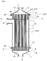
本発明の第1実施形態にかかるカートリッジ式中空糸膜モジュールの構成について、図面を参照しながら説明する。図1は、本発明の第1実施形態にかかるカートリッジ式中空糸膜モジュールの概略縦断面図である。Hereinafter, a cartridge type hollow fiber membrane module according to an embodiment of the present invention will be described in detail with reference to the drawings. In the present invention, “upper” and “lower” are based on the state shown in the drawings and are for convenience. The side in which the stock solution flows is the “down” direction and the side in which the filtrate flows out. “Up” direction. Usually, in the posture when the hollow fiber membrane module is used, the vertical direction coincides with the vertical direction in the drawing.
(First embodiment)
The configuration of the cartridge type hollow fiber membrane module according to the first embodiment of the present invention will be described with reference to the drawings. FIG. 1 is a schematic longitudinal sectional view of a cartridge type hollow fiber membrane module according to the first embodiment of the present invention.
第1実施形態にかかるカートリッジ式中空糸膜モジュールは、筐体と、前記筐体内に収容された複数の中空糸膜と、前記中空糸膜の第1端部を開口した状態で束ねる第1ポッティング部と、前記中空糸膜の第2端部を封止した状態で束ねる第2ポッティング部と、前記第1ポッティング部と前記筐体との間を液密に封止するシール部と、を備えている。 The cartridge-type hollow fiber membrane module according to the first embodiment includes a housing, a plurality of hollow fiber membranes housed in the housing, and a first potting bundled in a state where a first end of the hollow fiber membrane is opened. A second potting portion that is bundled in a state where the second end portion of the hollow fiber membrane is sealed, and a seal portion that seals the space between the first potting portion and the housing in a liquid-tight manner. ing.
<モジュール構造>
図1に示すように、カートリッジ式中空糸膜モジュール101Aは、筐体と、筐体内に収容された図2に示す中空糸膜カートリッジ100とを備える。<Module structure>
As shown in FIG. 1, the cartridge type hollow
筐体は、中空状の筐体本体3と、該筐体本体3の両端部に設けられた上部キャップ4と下部キャップ5とで構成されている。
The housing includes a
図1に示したように、筐体本体3の上部には、ろ過液出口7を有する上部キャップ4が、筐体本体3の下部には、原液流入口6を有する下部キャップ5がそれぞれ、液密かつ気密に接続されている。上部キャップ4および下部キャップ5は、例えば図1に示したようにガスケット17を使用し、クランプ等で筐体本体3に固定される。
As shown in FIG. 1, an
筐体本体3は、その上端および下端に筐体本体3の全周に亘って鍔部3A,3Bを有している。また、筐体本体3の側部には、ろ過液出口7寄りに原液出口8が設けられている。
The
上部キャップ4は筐体本体3の内径と略等しい内径を有し、その上端側が縮径してろ過液出口7を形成している。上部キャップ4の下端側には、筐体本体3と接続したときに溝を形成するための段部4Aが上部キャップ4の全周に亘って形成されている。筐体本体3と上部キャップ4を接続した際に上部キャップ4の下端部が筐体本体3の鍔部3Aと当接して溝(固定部)が形成され、この溝(固定部)により後述する第1ポッティング部11の鍔部11Dを固定する。
The
下部キャップ5は筐体本体3の内径と略等しい内径を有し、その下端側が縮径して原液流入口6を形成している。
The
図4は図1のモジュールの第1ポッティング位置におけるA−A線断面図である。 FIG. 4 is a cross-sectional view taken along line AA in the first potting position of the module of FIG.
<カートリッジ>
図2に示すように、中空糸膜カートリッジ100は、複数の中空糸膜1を含む中空糸膜束2と、中空糸膜束2の両端に設けられ、中空糸膜1間を接着するポッティング部とを備える。ポッティング部として、中空糸膜カートリッジ100は、筐体のろ過液出口7側に配置される第1ポッティング部11と、筐体の原液流入口6側に配置される第2ポッティング部12とを有する。<Cartridge>
As shown in FIG. 2, a hollow
<第1ポッティング部>
筐体のろ過液出口7側、つまり中空糸膜カートリッジ100の上端側に配置される第1ポッティング部11は、中空糸膜束2の第1端部において、中空糸膜1間を接着するポッティング剤で形成されている。<First potting part>
The
ここで、中空糸膜束2は、中空糸膜1の上方の端面が開口された状態で束ねられている。第1ポッティング部11は円柱状であり、その上端部には第1ポッティング部11の全周に亘って鍔部11Dが設けられている。また、第1ポッティング部11の側面には、全周にわたって、段部11Eが設けられている。段部11Eが設けられることで、第1ポッティング部11の上部の外径は、下部の外径よりも大きくなっている。
Here, the hollow
第1ポッティング部11の鍔部11Dは、筐体本体3に上部キャップ4が装着されることで筐体本体3と上部キャップ4との間に形成された溝(固定部)に挿入される。こうして、第1ポッティング部11は、筐体本体3の上端部に固定される。第1ポッティング部の段部11Eと筐体本体3の間にはOリング15を設置し、第1ポッティング部を液密、かつ気密に固定している。ここでOリング15を中空糸膜モジュールの径方向(図1の横方向)につぶすことで第1ポッティング部11を液密、かつ気密に固定している。シール性を確保するため、Oリングのつぶし代は8%以上30%以下とすることが好ましい。
The
このように第1ポッティング部11は筐体本体3と直接接着せず、Oリング15によって液密、かつ気密に固定されている。そのため従来の中空糸膜モジュールのように、熱処理によって筐体とポッティング剤が剥離し、原液のろ過液側へのリークおよび雑菌汚染等の問題が発生することはない。以降Oリング等のシール材で第1ポッティング部を液密、かつ気密に固定することをシールと呼び、シール材で固定する部位をシール部位と呼ぶ。
As described above, the
Oリング15で第1ポッティング部11を液密かつ気密に固定するためには段部11Eの寸法を安定化させる必要がある。ポッティング剤としてはエポキシ樹脂またはポリウレタン樹脂が使用され、これらのポッティング剤は2液を混合し硬化させるが、硬化時に体積が収縮する。収縮により段部11Eの寸法の変化や、歪みが生じるとOリング等のシール材によりシールすることができず、原液がろ過液側へリークすることがある。
In order to fix the
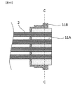
そこで本実施形態のカートリッジ式中空糸膜モジュールでは、第1ポッティング部11が、内層ポッティング部11Aと外層ポッティング部11Bとを備える。このようにポッティング部が2つ以上の層で形成されることで、ポッティング剤の硬化収縮によるポッティング部の寸法変化が抑制され、それによってシール材によるシール性を確保することができる。
Therefore, in the cartridge type hollow fiber membrane module of the present embodiment, the
より詳細には、外層ポッティング部11Bは、内層ポッティング部11Aが充分に硬化収縮した後に、内層ポッティング部11Aの外側に形成されればよい。外層ポッティング部11Bが形成されるときには、内層ポッティング部11Aは既に硬化収縮しているため、最終的な第1ポッティング部11の外形に生じる寸法のずれは、外層ポッティング部11Bの硬化収縮のみに由来する。こうして、ポッティング部が単一の層で構成される場合よりも、寸法ずれが小さく抑えられる。
More specifically, the outer
また、シール方向の寸法ずれが小さいことがシール性を向上させるので、シール方向においては内層ポッティング部と外層ポッティング部の両方が形成されている必要がある。またシール方向とはシール材で第1ポッティング部を固定する際にシール材がつぶされる方向のことである。例えば図3において、Oリング15は左右方向につぶされる。そして、Oリング15に沿った断面(図1のA−A断面)に、内層ポッティング部11Aおよび外層ポッティング部11Bの両方が含まれる(図4)。
Further, since a small dimensional deviation in the sealing direction improves the sealing performance, both the inner layer potting portion and the outer layer potting portion need to be formed in the sealing direction. The sealing direction is a direction in which the sealing material is crushed when the first potting portion is fixed with the sealing material. For example, in FIG. 3, the O-
尚、内層ポッティング部は円柱等の単純な形状でよい。本実施形態では、第1ポッティング部11の表面に設けられる鍔部11Dおよび段部11E等の構造は、外層ポッティング部11Bによって形成される。ただし、本発明はこれに限定されるものではなく、例えば、内層ポッティング部11Aも段部や鍔部等の構造を備えていてもよい。
The inner layer potting portion may be a simple shape such as a cylinder. In the present embodiment, the structures such as the
本実施形態において、外層ポッティング部11Bは、シール部材に接する。つまり、第1ポッティング部11の外表面が外層ポッティング部11Bで形成されている。
In the present embodiment, the outer
第1ポッティング部11の中で外層ポッティング部11Bが占める割合を少なくするほど全体の寸法変化を抑制することができる。第1ポッティング部の寸法変化を抑制し、シール性を確保するためには第1ポッティング部11のシール部位において、シール方向の第1ポッティング部の長さ[mm]に対する、シール方向で外層ポッティング部が占める長さ[mm]の比率を表すP(%)が下記式(1)を満たすことが必要である。
As the ratio of the outer
P≦16・・・(1)
ここでシール部位とは第1ポッティング部でOリングやガスケットなどのシール材を装着する部位のことである。図1のカートリッジ式中空糸膜モジュール101Aではポッティング部をOリング15によりモジュールの径方向でシールしており、シール方向における外層ポッティング部が占める長さは、図3のD2a+D2bであり、シール方向における第1ポッティング部の長さは図3のDである。P ≦ 16 (1)
Here, the seal part is a part where a sealing material such as an O-ring or a gasket is attached in the first potting part. In the cartridge type hollow
ポッティング剤として使用されるエポキシ樹脂やポリウレタン樹脂の硬化収縮率(線収縮率)は一般的に約0.2〜1%である。上記式(1)のPは、使用するポッティング剤の硬化収縮率によって、上述の範囲内で適宜設定すれば良い。 The cure shrinkage (linear shrinkage) of epoxy resins and polyurethane resins used as potting agents is generally about 0.2 to 1%. P in the above formula (1) may be appropriately set within the above range depending on the curing shrinkage rate of the potting agent to be used.
例えばポッティング剤の硬化収縮率が1%の場合、第1ポッティング部を単層構造とすると1%寸法が変化してしまう。硬化収縮は均一には起こらないため、第1ポッティング部のシール部は歪んだ構造となる。そのためシール材のつぶし代が十分に確保できない場所が発生し、原液がろ過液側にリークする可能性がある。 For example, when the curing shrinkage rate of the potting agent is 1%, if the first potting portion has a single layer structure, the dimension changes by 1%. Since the curing shrinkage does not occur uniformly, the seal portion of the first potting portion has a distorted structure. Therefore, a place where the crushing cost of the sealing material cannot be secured sufficiently occurs, and the stock solution may leak to the filtrate side.
これに対して、第1ポッティング部を内層ポッティング部と外層ポッティング部の二層構造とすれば、寸法変化を小さく抑えることができる。具体的には、ポッティング剤の硬化収縮率が1%の場合、上記式(1)のPを16%以下にすれば寸法変化を0.3%に抑制することができ、シール性を向上させることができる。 On the other hand, if the first potting portion has a two-layer structure of the inner layer potting portion and the outer layer potting portion, the dimensional change can be suppressed small. Specifically, when the curing shrinkage rate of the potting agent is 1%, the dimensional change can be suppressed to 0.3% by reducing P in the above formula (1) to 16% or less, and the sealing performance is improved. be able to.
また外層ポッティング部の厚みは2mm以上とすることが好ましく、4mm以上がより好ましい。外層ポッティング部の厚みが上記好ましい範囲であると、内層ポッティング部とポッティングキャップとの間の流路を十分に確保でき、ポッティング時に気泡等が残留しにくいのでシール部に欠陥が発生するのを防ぐことができる。 The thickness of the outer layer potting part is preferably 2 mm or more, and more preferably 4 mm or more. When the thickness of the outer layer potting portion is within the above-mentioned preferable range, a sufficient flow path between the inner layer potting portion and the potting cap can be secured, and bubbles and the like hardly remain at the time of potting, thereby preventing the seal portion from being defective. be able to.
本実施形態では、第1ポッティング部の全体がポッティング剤で形成されている。第1ポッティング部11の最外層が、すなわち第1ポッティング部11においてOリング15に接触する部分が、外層ポッティング部である。ここで外層ポッティング部のうち、Oリング15に接触部分をシール面と呼ぶが、シール性を確保するためにはこのシール面の算術平均粗さRaを1.6μm以下とすることが好ましい。シール面の算術平均粗さRaが上記好ましい範囲であると、シール面とシール材の間に隙間が発生しにくく、リークが発生するのを防ぐことができる。ここでシール面の算術平均粗さを1.6μm以下とするためには、ポッティングに使用するポッティングキャップのうち、シール面を形成する面の算術平均粗さRaを1.6μm以下とする方法が挙げられる。エポキシ樹脂やポリウレタン等のポッティング剤は液状の状態でポッティングキャップに充填され、その後硬化するが、ポッティングキャップの表面の算術平均粗さRaを1.6μm以下とすることで、その面に接触した状態で硬化したポッティング剤表面の算術平均粗さRaを1.6μm以下とすることができる。尚、ポッティングキャップの材質は、ポッティング剤の離型性の良い材質のものを使用することが好ましく、例えばフッ素系樹脂、ポリプロピレン、ポリアセタール、ポリエチレンなどを使用することができる。
In the present embodiment, the entire first potting portion is formed of a potting agent. The outermost layer of the
例えば図16の中空糸膜モジュール102のようにポッティング部の最外層があらかじめ形成されたケースである場合、つまり、ポッティング部が、ケースとそのケース内に充填されたポッティング剤とを備える場合、ポッティング剤の硬化収縮によって、ケースとの間に引張応力が発生し、剥離が生じやすい。
For example, in the case where the outermost layer of the potting portion is formed in advance as in the hollow
しかし、本実施形態の構成によれば、第1ポッティング部11が内層ポッティング部11Aおよび外層ポッティング部11Bのみによって形成されている。つまり、第1ポッティング部11全体が、ポッティング剤によって形成されている。このような形状では、内層ポッティング部11Aと外層ポッティング部11Bとの間に引張応力は発生せず、剥離が生じにくい。
However, according to the configuration of the present embodiment, the
カートリッジ式中空糸膜モジュールの内層ポッティング部および外層ポッティング部で使用するポッティング剤の種類は、接着対象部材との接着強度、耐熱性、化学的耐久性などを満たせば特に限定されないが、例えばエポキシ樹脂やポリウレタン樹脂などを使用することが好ましい。エポキシ樹脂やポリウレタン樹脂は中空糸膜との接着性、耐熱性、化学的耐久性に優れているものが多く、本実施形態のカートリッジ式中空糸膜モジュールのポッティング剤として好適に使用することができる。 The type of potting agent used in the inner layer potting portion and the outer layer potting portion of the cartridge type hollow fiber membrane module is not particularly limited as long as it satisfies the adhesive strength, heat resistance, chemical durability, etc. with the member to be bonded. It is preferable to use polyurethane resin or the like. Many epoxy resins and polyurethane resins are excellent in adhesion to the hollow fiber membrane, heat resistance, and chemical durability, and can be suitably used as a potting agent for the cartridge type hollow fiber membrane module of this embodiment. .
ここで外層ポッティング部を形成するポッティング剤の125℃における圧縮降伏応力は10MPa以上であることが好ましく、15MPa以上とすることがさらに好ましい。蒸気滅菌では滅菌部位を121℃以上に昇温する必要があるところ、放熱により温度が低下することから、実際には125℃から130℃程度の蒸気を供給して蒸気滅菌を行うことが多い。ここで125℃におけるポッティング剤の圧縮降伏応力が上記好ましい範囲であると、蒸気滅菌時の膨張により外層ポッティング部のシール面がシール材に押されても塑性変形しにくく、凹みが発生しにくい。塑性変形による凹みが発生しにくいので、常温に戻して収縮したときにシール面に凹みが残存しにくいため、十分にシール材のつぶし代を確保することができ、リークが発生するのを有効に防ぐことができる。 Here, the compressive yield stress at 125 ° C. of the potting agent forming the outer layer potting portion is preferably 10 MPa or more, and more preferably 15 MPa or more. In steam sterilization, it is necessary to raise the temperature of the sterilization site to 121 ° C. or higher. However, since the temperature is decreased by heat radiation, in practice, steam sterilization is often performed by supplying steam at about 125 ° C. to 130 ° C. Here, when the compressive yield stress of the potting agent at 125 ° C. is in the above preferred range, even if the sealing surface of the outer layer potting portion is pushed by the sealing material due to expansion during steam sterilization, it is difficult for plastic deformation and dents are hardly generated. Since dents due to plastic deformation are unlikely to occur, dents are unlikely to remain on the sealing surface when contracted after returning to normal temperature, so it is possible to secure a sufficient crushing margin for the sealing material and effectively prevent leakage. Can be prevented.
また外層ポッティング部を形成するポッティング剤の80℃における引張強度は5MPa以上であることが好ましく、10MPa以上とすることがさらに好ましい。また、引張強度が低下するのを有効に防止するため、ガラス転移点が80℃以上のポッティング剤を使用することが好ましい。本発明のカートリッジ式中空糸膜モジュールは高温の液体のろ過に使用することも可能である。例えば高濃度の糖液の場合、温度を60℃〜80℃とすることで粘度を低減してろ過を行うことがある。カートリッジ式中空糸膜モジュール101Aでは第1ポッティング部の鍔部11Dを、筐体本体3の鍔部3Aと上部キャップ4の段部4Aの間に挟むことで第1ポッティング部の軸方向の移動を規制しているが、ろ過または逆圧洗浄により、モジュールの原液側とろ過液側に圧力差が発生すると、第1ポッティング部の鍔部11Dを上向きまたは下向きに押す応力が発生する。ここで外層ポッティング部を形成するポッティング剤の80℃における引張強度が上記好ましい範囲であると、高温液のろ過または逆圧洗浄時に発生する応力で鍔部11Dにクラックが発生しにくく、第1ポッティング部の位置がずれにくいのでリークが発生するのを有効に防ぐことができる。カートリッジ式中空糸膜モジュール101Aでは第1ポッティング部の鍔部11Dで第1ポッティング部の軸方向の移動を規制しているが、シール材によるシール性を確保するためには第1ポッティング部に段差を設けて支持することで、第1ポッティング部の軸方向の移動を規制する必要がある。従ってカートリッジ式中空糸膜モジュール101A以外の形態の場合も、第1ポッティング部にはろ過または逆圧洗浄時に上述のような応力が発生する部位が存在する。
Further, the tensile strength at 80 ° C. of the potting agent forming the outer layer potting portion is preferably 5 MPa or more, and more preferably 10 MPa or more. In order to effectively prevent the tensile strength from being lowered, it is preferable to use a potting agent having a glass transition point of 80 ° C. or higher. The cartridge type hollow fiber membrane module of the present invention can also be used for filtration of a high-temperature liquid. For example, in the case of a high-concentration sugar solution, the temperature may be 60 ° C. to 80 ° C. to reduce the viscosity and perform filtration. In the cartridge type hollow fiber membrane module 101 </ b> A, the
本発明の中空糸膜モジュールの外層ポッティング部に使用するポッティング剤としては例えばエポキシ樹脂やポリウレタンを使用することができるが、耐熱性の観点からエポキシ樹脂を使用することが好ましい。エポキシ樹脂は主剤と硬化剤を反応させて硬化させるが、主剤としては例えばビスフェノールA型エポキシ樹脂、ビスフェノールF型エポキシ樹脂、ノボラック型エポキシ樹脂、ナフタレン型エポキシ樹脂、ビフェニル型エポキシ樹脂、シクロペンタジエン型エポキシ樹脂などが挙げられる。これらは単独で用いても良く、2種類以上併用しても良い。また硬化剤としては例えば脂肪族アミン、ポリエーテルアミン、芳香族アミン、有機酸無水物などが挙げられるが、中でも脂肪族アミンおよびその変性物を使用することが好ましい。脂肪族アミンは反応性に富み、常温雰囲気下でも反応を進行させ、高温時の圧縮降伏応力および引張強度の高いエポキシ樹脂を得ることができる。脂肪族アミンとしては例えばトリエチレンテトラミン、ジメチルアミノプロピルアミン、ジエチレントリアミン、テトラエチレンペンタミン、ジプロプレンジアミン、ヘキサメチレンジアミン、N−アミノエチルピペラジン、m−キシレンジアミン、またはこれらの変性物などが挙げられる。これらは単独で用いても良く、2種類以上併用しても良い。また反応物の耐熱性を損なわない範囲であれば、例えば、ポリエーテルアミン、ポリアミド、アミンアダクトなど、その他の種類の硬化剤を併用することもできる。 As a potting agent used for the outer layer potting portion of the hollow fiber membrane module of the present invention, for example, epoxy resin or polyurethane can be used, but it is preferable to use an epoxy resin from the viewpoint of heat resistance. The epoxy resin is cured by reacting the main agent and the curing agent. Examples of the main agent include bisphenol A type epoxy resin, bisphenol F type epoxy resin, novolac type epoxy resin, naphthalene type epoxy resin, biphenyl type epoxy resin, cyclopentadiene type epoxy. Resin etc. are mentioned. These may be used alone or in combination of two or more. Examples of the curing agent include aliphatic amines, polyether amines, aromatic amines, and organic acid anhydrides. Among them, aliphatic amines and modified products thereof are preferably used. Aliphatic amines are rich in reactivity, and the reaction proceeds even under a normal temperature atmosphere, and an epoxy resin having a high compressive yield stress and high tensile strength at high temperatures can be obtained. Examples of the aliphatic amine include triethylenetetramine, dimethylaminopropylamine, diethylenetriamine, tetraethylenepentamine, dipropylenediamine, hexamethylenediamine, N-aminoethylpiperazine, m-xylenediamine, and modified products thereof. . These may be used alone or in combination of two or more. In addition, as long as the heat resistance of the reaction product is not impaired, other types of curing agents such as polyetheramine, polyamide, and amine adduct can be used in combination.
ただし硬化剤として脂肪族アミンを使用すると、反応熱により100℃以上の高温となり、発煙する場合やポッティングキャップを溶融させてしまう場合がある。発熱を抑えるためにはシリカやガラス繊維、炭酸カルシウム等のフィラーを混合する方法が有効であり、ポッティング剤中のフィラーの割合は20重量%以上80重量%以下とすることが好ましい。フィラーの割合が上記好ましい範囲であると、発熱を抑える効果が高い一方、粘度が高過ぎることもなく、ポッティングに使用するのに適切である。またフィラーを混合すると圧縮降伏応力および引張強度を高める効果もある。尚シリカなどのフィラーを使用する場合、シランカップリング剤を添加することで、エポキシ樹脂とフィラーの接着強度を高めることができる。特に第1ポッティング部の直径が100mm以上の大型の中空糸膜モジュールでは、第1ポッティング部の比表面積が小さく、放熱が少ないため、反応時の発熱により高温になりやすく、上述の発煙などの問題が発生しやすい。ただし本発明のカートリッジ中空糸膜モジュールの外層ポッティング部は内層ポッティング部の外側のみに存在し、比表面積が大きいため、放熱が大きく、第1ポッティング部の直径が100mm以上の大型の中空糸膜モジュールでも過剰に高温になることを防ぐことができる。 However, when an aliphatic amine is used as a curing agent, the temperature of the reaction may increase to 100 ° C. or higher due to heat of reaction, which may cause smoke or melt the potting cap. In order to suppress heat generation, a method of mixing fillers such as silica, glass fiber, calcium carbonate and the like is effective, and the ratio of the filler in the potting agent is preferably 20% by weight or more and 80% by weight or less. When the ratio of the filler is within the above preferable range, the effect of suppressing heat generation is high, while the viscosity is not too high, and it is suitable for use in potting. Mixing fillers also has the effect of increasing compressive yield stress and tensile strength. In addition, when using fillers, such as a silica, the adhesive strength of an epoxy resin and a filler can be improved by adding a silane coupling agent. In particular, in the case of a large hollow fiber membrane module having a diameter of 100 mm or more in the first potting part, the specific surface area of the first potting part is small and the heat radiation is small, so that it tends to become high temperature due to heat generation during the reaction, and the above-mentioned problems such as smoke generation Is likely to occur. However, the outer layer potting portion of the cartridge hollow fiber membrane module of the present invention exists only outside the inner layer potting portion, and since the specific surface area is large, heat dissipation is large and the diameter of the first potting portion is 100 mm or more. But it can prevent excessively high temperatures.
一方内層ポッティング部については放熱が少なく高温になりやすいため、特に第1ポッティング部の直径が100mm以上の大型の中空糸膜モジュールでは、外層ポッティング部と比べて反応熱の小さいポッティング剤を使用することが好ましい。内層ポッティング部のポッティング剤は十分な耐熱性を有するものが好ましく、例えばエポキシ樹脂やポリウレタンなどを使用することができる。エポキシ樹脂を使用する場合、主剤としては例えばビスフェノールA型エポキシ樹脂、ビスフェノールF型エポキシ樹脂、ノボラック型エポキシ樹脂、ナフタレン型エポキシ樹脂、ビフェニル型エポキシ樹脂、シクロペンタジエン型エポキシ樹脂などが挙げられる。これらは単独で用いても良く、2種類以上併用しても良い。また硬化剤としてはポリエーテルアミン、ポリアミド、アミンアダクトなどが挙げられる。これらは単独で用いても良く、2種類以上併用しても良い。さらに反応熱が過剰に高くならない範囲であれば、脂肪族アミンなど、その他の種類の硬化剤を併用することもできる。またエポキシ樹脂にシリカやガラス繊維、炭酸カルシウム等のフィラーを混合しても良い。 On the other hand, since the inner layer potting part has a low heat dissipation and is likely to reach a high temperature, a potting agent having a smaller reaction heat than that of the outer layer potting part should be used particularly in a large hollow fiber membrane module having a diameter of the first potting part of 100 mm or more. Is preferred. The potting agent for the inner layer potting portion is preferably one having sufficient heat resistance, and for example, an epoxy resin or polyurethane can be used. In the case of using an epoxy resin, examples of the main agent include bisphenol A type epoxy resin, bisphenol F type epoxy resin, novolac type epoxy resin, naphthalene type epoxy resin, biphenyl type epoxy resin, cyclopentadiene type epoxy resin and the like. These may be used alone or in combination of two or more. Examples of the curing agent include polyetheramine, polyamide, and amine adduct. These may be used alone or in combination of two or more. Furthermore, other kinds of curing agents such as aliphatic amines can be used in combination as long as the heat of reaction does not become excessively high. Moreover, you may mix a filler, such as a silica, glass fiber, and calcium carbonate, with an epoxy resin.
一方ポリウレタンは、イソシアネートとポリオールを反応させて得ることができる。内層ポッティング部のポッティング剤としてポリウレタンを使用する場合、イソシアネートは、例えばトリレンジイソシアネート(TDI)、ジフェニルメタンジイソシアネート(MDI)、ポリメチレンポリフェニルイソシアネート(ポリメリックMDI)、キシリレンジイソシアネート(XDI)などが挙げられる。これらは単独で用いても良く、2種類以上併用しても良い。ポリオールは、例えばポリブタジエン系ポリオール、ダイマー酸変性ポリオール、エポキシ樹脂変性ポリオール、ポリテトラメチレングリコールなどが挙げられる。これらは単独で用いても良く、2種類以上併用しても良い。また反応物の耐湿熱性を損なわない範囲であれば、例えば、ひまし油系ポリオール、ポリカーボネートジオール、ポリエステルポリオールなど、その他の種類のポリオールを併用することもできる。 On the other hand, polyurethane can be obtained by reacting isocyanate and polyol. When polyurethane is used as a potting agent for the inner layer potting part, examples of the isocyanate include tolylene diisocyanate (TDI), diphenylmethane diisocyanate (MDI), polymethylene polyphenyl isocyanate (polymeric MDI), and xylylene diisocyanate (XDI). . These may be used alone or in combination of two or more. Examples of the polyol include a polybutadiene-based polyol, a dimer acid-modified polyol, an epoxy resin-modified polyol, and polytetramethylene glycol. These may be used alone or in combination of two or more. In addition, other types of polyols such as castor oil-based polyol, polycarbonate diol, and polyester polyol can be used in combination as long as the heat and humidity resistance of the reaction product is not impaired.
また内層ポッティング部と外層ポッティング部は線膨張係数の近いポッティング剤を使用することが好ましい。内層ポッティング部と外層ポッティング部の線膨張係数が近いと、蒸気加熱時の熱膨張の差が小さいため、内層ポッティング部と外層ポッティング部の間に発生する応力が小さくなり、剥離が発生しにくい。 Moreover, it is preferable to use a potting agent having a linear expansion coefficient close to the inner layer potting portion and the outer layer potting portion. When the linear expansion coefficients of the inner layer potting portion and the outer layer potting portion are close, the difference in thermal expansion during steam heating is small, so that the stress generated between the inner layer potting portion and the outer layer potting portion is reduced, and peeling is unlikely to occur.
尚、第1ポッティング部は三層以上の複層構造としても良い。その場合シール方向において最も外側のポッティング層が外層ポッティング部である。また内層ポッティング部を複数に分割し、複数の内層ポッティング部同士の間と、その外周全体を外層ポッティング部で形成させることもできる。 Note that the first potting portion may have a multilayer structure of three or more layers. In that case, the outermost potting layer in the sealing direction is the outer layer potting portion. Further, the inner layer potting portion may be divided into a plurality of portions, and the outer layer potting portion may be formed between the plurality of inner layer potting portions and the entire outer periphery thereof.
また、第1実施形態では図4に示すように内層ポッティング部11Aのみで中空糸膜1を接着しているが、外層ポッティング部11B部分においても中空糸膜1を接着することができる。
In the first embodiment, as shown in FIG. 4, the
<第2ポッティング部>
筐体の原液流入口6側には、中空糸膜カートリッジ100の下端側である第2ポッティング部12が配置されている。中空糸膜1の第2端部が位置する第2ポッティング部12は、多数本の中空糸膜1からなる中空糸膜束2と第2ポッティング部ケース13をポッティング剤で接着して構成されている。ここで、中空糸膜1の中空部はポッティング剤で封止されて開口しない状態となっている。第2ポッティング部ケース13は下方に底部を有する円筒状であり、その外径は筐体本体3の内径よりも小さく構成されている。また、第2ポッティング部12は貫通孔14を有しており、原液の流路の役割を担っている。<Second potting part>
A
カートリッジ式中空糸膜モジュールの第2ポッティング部で使用するポッティング剤の種類は、接着対象部材との接着強度、耐熱性、化学的耐久性などを満たせば特に限定されないが、例えばエポキシ樹脂やポリウレタン樹脂などを使用することができる。 The type of potting agent used in the second potting part of the cartridge type hollow fiber membrane module is not particularly limited as long as it satisfies the adhesive strength, heat resistance, chemical durability, etc. with the member to be bonded. For example, epoxy resin or polyurethane resin Etc. can be used.
図5は、図1のモジュールの第2ポッティング位置におけるB−B線断面図である。 FIG. 5 is a cross-sectional view taken along line BB in the second potting position of the module of FIG.
<中空糸膜>
本実施形態のカートリッジ式中空糸膜モジュールは、分離膜として、中空糸膜を備える。中空糸膜は一般的に平膜よりも比表面積が大きく、単位時間当たりにろ過できる液量が多いため有利である。中空糸膜の構造としては全体的に孔径が一様な対称膜や、膜の厚み方向で孔径が変化する非対称膜、強度を保持するための支持層と対象物質の分離を行うための分離機能層を有する複合膜などが存在する。<Hollow fiber membrane>
The cartridge type hollow fiber membrane module of this embodiment includes a hollow fiber membrane as a separation membrane. A hollow fiber membrane is advantageous because it generally has a specific surface area larger than that of a flat membrane and a larger amount of liquid can be filtered per unit time. The structure of the hollow fiber membrane is a symmetric membrane with a uniform pore size as a whole, an asymmetric membrane whose pore size changes in the thickness direction of the membrane, and a separation function for separating the support layer and the target substance to maintain strength There are composite membranes having layers.
中空糸膜の平均孔径は分離対象によって適宜選択すれば良いが、細菌類や真菌類などの微生物や、動物細胞の分離などを目的とする場合、10nm以上、220nm以下であることが好ましい。平均孔径が10nm未満だと透水性が低くなり、220nmを超えると微生物等が漏洩する可能性がある。一方低分子量のタンパク質などの分離を行う場合、平均孔径が2nm〜20nmの中空糸膜を使用することが好ましい。本発明での平均孔径とは最も孔径の小さい緻密層の孔径とする。 The average pore diameter of the hollow fiber membrane may be appropriately selected depending on the separation target, but is preferably 10 nm or more and 220 nm or less for the purpose of separation of microorganisms such as bacteria and fungi and animal cells. If the average pore size is less than 10 nm, the water permeability becomes low, and if it exceeds 220 nm, microorganisms and the like may leak. On the other hand, when separating low molecular weight proteins or the like, it is preferable to use a hollow fiber membrane having an average pore diameter of 2 nm to 20 nm. The average pore size in the present invention is the pore size of the dense layer having the smallest pore size.
分離膜の材質は特に限定されないが、分離膜は、例えばポリテトラフルオロエチレン、ポリフッ化ビニリデン、ポリフッ化ビニル、四フッ化エチレン・六フッ化プロピレン共重合体、エチレン・四フッ化エチレン共重合体などのフッ素系樹脂、セルロースアセテート、セルロースアセテートプロピオネート、セルロースアセテートブチレートなどのセルロースエステル、ポリスルホン、ポリエーテルスルホンなどのポリスルホン系樹脂、ポリアクリロニトリル、ポリイミド、ポリプロピレンなどの樹脂を含有することができる。特にフッ素系樹脂やポリスルホン系樹脂からなる分離膜は耐熱性、物理的強度、化学的耐久性が高いことから、カートリッジ式中空糸膜モジュールに好適に用いることができる。 The material of the separation membrane is not particularly limited. Examples of the separation membrane include polytetrafluoroethylene, polyvinylidene fluoride, polyvinyl fluoride, ethylene tetrafluoride / hexafluoropropylene copolymer, and ethylene / tetrafluoroethylene copolymer. Fluorine resins such as cellulose acetate, cellulose acetate propionate, cellulose esters such as cellulose acetate butyrate, polysulfone resins such as polysulfone and polyethersulfone, resins such as polyacrylonitrile, polyimide, and polypropylene can be contained. . In particular, a separation membrane made of a fluorine resin or a polysulfone resin has high heat resistance, physical strength, and chemical durability, and therefore can be suitably used for a cartridge type hollow fiber membrane module.
また、中空糸膜は、フッ素系樹脂やポリスルホン系樹脂に加えて、親水性樹脂をさらに含有してもよい。親水性樹脂によって、分離膜の親水性を高め、膜の透水性を向上させることができる。親水性樹脂は、分離膜に親水性を付与することができる樹脂であればよく、具体的な化合物に限定されるものではないが、例えば、セルロースエステル、脂肪酸ビニルエステル、ビニルピロリドン、エチレンオキサイド、プロピレンオキサイド、ポリメタクリル酸エステル系樹脂、及びポリアクリル酸エステル系樹脂などが好適に用いられる。 The hollow fiber membrane may further contain a hydrophilic resin in addition to the fluorine-based resin or the polysulfone-based resin. With the hydrophilic resin, the hydrophilicity of the separation membrane can be increased and the water permeability of the membrane can be improved. The hydrophilic resin may be any resin that can impart hydrophilicity to the separation membrane, and is not limited to a specific compound. For example, cellulose ester, fatty acid vinyl ester, vinyl pyrrolidone, ethylene oxide, Propylene oxide, polymethacrylic acid ester resin, polyacrylic acid ester resin and the like are preferably used.
中空糸膜カートリッジを作製する場合はポッティングキャップに中空糸膜を充填し、ポッティング剤で固定する。その際、ハンドリングを良好にし、接着不良を防止する観点から、予め中空糸膜を乾燥させておく。しかし中空糸膜の多くは乾燥により収縮が起こり、透水性が低下するという問題があるため、グリセリン水溶液に浸漬した後で乾燥させたものを用いる。グリセリン水溶液に浸漬した後で乾燥すると、グリセリンが細孔内に残留することで乾燥による収縮を防止することができ、その後エタノールなどの溶媒で浸漬処理を行うことで透水性を回復させることができる。 When producing a hollow fiber membrane cartridge, the potting cap is filled with the hollow fiber membrane and fixed with a potting agent. At that time, the hollow fiber membrane is dried in advance from the viewpoint of good handling and prevention of adhesion failure. However, most of the hollow fiber membranes have a problem that shrinkage occurs due to drying and water permeability is lowered. Therefore, a hollow fiber membrane is used after being dipped in an aqueous glycerin solution. When dried after immersing in an aqueous glycerin solution, glycerin remains in the pores, so that shrinkage due to drying can be prevented, and water permeability can be restored by performing immersion treatment with a solvent such as ethanol after that. .
カートリッジ式中空糸膜モジュールは、蒸気滅菌してから使用することも可能だが、中空糸膜の種類によっては蒸気滅菌により収縮が起こるものがある。そのためモジュール作製後に蒸気滅菌を行うと中空糸膜の収縮により中空糸膜が損傷したり、中空糸膜がポッティング剤から剥離したりする可能性がある。従って予め中空糸膜を蒸気処理し、収縮させてからポッティングを行ってモジュールを製作することが望ましい。一般的に蒸気滅菌は121℃以上で実施するため、121℃以上の蒸気で前処理を実施しておくことが望ましい。 The cartridge-type hollow fiber membrane module can be used after steam sterilization, but some types of hollow fiber membranes contract due to steam sterilization. Therefore, when steam sterilization is performed after the module is manufactured, the hollow fiber membrane may be damaged due to shrinkage of the hollow fiber membrane, or the hollow fiber membrane may be peeled off from the potting agent. Therefore, it is desirable to produce a module by steaming the hollow fiber membrane in advance and shrinking it before potting. Since steam sterilization is generally performed at 121 ° C. or higher, it is desirable to perform pretreatment with steam at 121 ° C. or higher.
<シール材>
カートリッジ式中空糸膜モジュールで使用するOリングやガスケットなどのシール材の材質は耐熱性、化学的耐久性などを満たせば特に限定されないが、例えばフッ素ゴム、シリコーンゴム、エチレンプロピレンジエンゴム(EPDM)などを使用することができる。<Seal material>
The material of the sealing material such as an O-ring or gasket used in the cartridge type hollow fiber membrane module is not particularly limited as long as it satisfies heat resistance and chemical durability. For example, fluorine rubber, silicone rubber, ethylene propylene diene rubber (EPDM) Etc. can be used.
<筐体、筒状ケースの材質>
カートリッジ式中空糸膜モジュールで使用する筐体の材質は耐熱性、化学的耐久性などを満たせば特に限定されないが、例えばポリスルホン系樹脂、ポリテトラフルオロエチレン、ペルフルオロアルコキシフッ素樹脂などのフッ素系樹脂、ポリカーボネート、ポリプロピレン、ポリメチルペンテン、ポリフェニレンサルファイド、ポリエーテルケトン、ステンレス、アルミニウムなどを挙げることができる。またカートリッジ式中空糸膜モジュールで使用する筒状ケースおよび第2ポッティング部ケースの材質は特に限定されないが、例えば筐体と同様の材料から選択することができる。
(第2実施形態)
本発明の第2実施形態にかかるカートリッジ式中空糸膜モジュール101Bの構成について、図面を参照しながら説明する。図6は、第2実施形態にかかるカートリッジ式中空糸膜モジュール101Bの概略縦断面図である。尚、以下で言及しないカートリッジ式中空糸膜モジュール101Bの構成については、第1実施形態のカートリッジ式中空糸膜モジュール101Aと同様の構造を適用可能である。第1実施形態で説明した部材と同様の機能を有する部材については、同じ符号を付して、その説明を省略する。<Material of casing and cylindrical case>
The material of the housing used in the cartridge type hollow fiber membrane module is not particularly limited as long as it satisfies heat resistance, chemical durability, etc., for example, fluorine resin such as polysulfone resin, polytetrafluoroethylene, perfluoroalkoxy fluorine resin, Examples thereof include polycarbonate, polypropylene, polymethylpentene, polyphenylene sulfide, polyether ketone, stainless steel, and aluminum. The material of the cylindrical case and the second potting part case used in the cartridge type hollow fiber membrane module is not particularly limited, but can be selected from, for example, the same material as that of the housing.
(Second Embodiment)
The configuration of the cartridge type hollow
第2実施形態にかかるカートリッジ式中空糸膜モジュール101Bでは、第1ポッティング部112は、保護ポッティング部11Cをさらに備える以外は、第1実施形態のカートリッジ式中空糸膜モジュール101Aと同様の構造である。保護ポッティング部11Cは、第1ポッティング部112の下面(第1ポッティング部112における第2ポッティング部12との対向面:第1ポッティング部112において中空糸膜が延在する面)に設けられる。
In the cartridge type hollow
一般に、モジュール内では、原液の流れにより、ポッティング部の端面において、ポッティング部との接触によって中空糸膜に大きな負担がかかるので、この部分で中空糸膜の破断が発生しやすい。 Generally, in the module, due to the flow of the stock solution, a large burden is imposed on the hollow fiber membrane due to contact with the potting portion at the end face of the potting portion, and the hollow fiber membrane is easily broken at this portion.
これに対して、本実施形態では、第1ポッティング部112が、伸度の大きいポッティング剤で形成された保護ポッティング部11Cを備える。液の流れやエアスクラビングにより中空糸膜1が揺動した際、保護ポッティング部11Cが伸張して中空糸膜1の動きに追随することで中空糸膜1にかかる負担を軽減することができる。こうして、保護ポッティング部11Cは、第1ポッティング部112の下面における中空糸膜1と第1ポッティング部112との接触による中空糸膜1への負担を軽減し、中空糸膜1の破断を抑制することができる。
On the other hand, in this embodiment, the
保護ポッティング部11Cを形成するポッティング剤としては、十分な耐熱性を有するもので、伸度が30%以上のものを使用することが好ましく、伸度が50%以上のものを使用することがさらに好ましい。保護ポッティング部11Cとしては、例えばエポキシ樹脂、ポリウレタン樹脂、シリコーン樹脂を使用することができる。また、保護ポッティング部11Cの伸度は、内層ポッティング部および外層ポッティング部の伸度よりも大きいことが好ましい。
As a potting agent for forming the
またカートリッジ式中空糸膜モジュール101Bの第2ポッティング部12は、図6のように中空糸膜束2とポッティング剤のみで形成させることもできる。第2ポッティング部については中空糸膜の中空部もポッティング剤で封止するため、第1実施形態(図1)の第2ポッティング部ケース13とポッティング剤が剥離しても原液がろ過液側にリークすることはない。ただし第2ポッティング部ケース13とポッティング剤が剥離すると、第2ポッティング部ケース13が脱落する場合や、剥離により生じた隙間に濁質が堆積する場合がある。第2ポッティング部12を中空糸膜束2とポッティング剤のみで形成すればこのような問題の発生を防止することができる。
Further, the
ここで第2ポッティング部12は図6のように中空糸膜束2で吊り下げた状態にしても良いし、ピン等で保持してモジュール軸方向の移動を規制しても良い。ピン等で第2ポッティング部12の軸方向の移動を規制すると、第2ポッティング部12の下方向への移動による中空糸膜の破断や、第2ポッティング部12の上方向への移動による中空糸膜の折れ曲がりなどを防止することができる。この場合、第2ポッティング部12でピンが当接する部分に荷重がかかるため、十分な強度を有するポッティング剤を使用することが好ましい。
(第3実施形態)
本発明の第3実施形態にかかるカートリッジ式中空糸膜モジュール101Cの構成について、図面を参照しながら説明する。Here, the
(Third embodiment)
A configuration of a cartridge type hollow
図7は、第3実施形態にかかるカートリッジ式中空糸膜モジュール101Cの第1ポッティング部付近の概略縦断面図である。以下で言及しないカートリッジ式中空糸膜モジュール101Cの構成については、第1実施形態のカートリッジ式中空糸膜モジュール101Aと同様の構造を適用可能である。第1実施形態で説明した部材と同様の機能を有する部材については、同じ符号を付して、その説明を省略する。第3実施形態にかかるカートリッジ式中空糸膜モジュール101Cは、筒状ケース9を備える以外は、第1実施形態のカートリッジ式中空糸膜モジュール101Aとほぼ同一の構成である。
FIG. 7 is a schematic longitudinal sectional view of the vicinity of the first potting portion of the cartridge type hollow
筒状ケース9は、略円筒形状の部材であり、その円筒形状の高さ方向が筐体本体3の高さ方向に沿うように、筐体本体3内に収容される。筒状ケース9の外面には、鍔部9Aおよび段部9Bが設けられている。鍔部9Aは、筒状ケース9の上端において、筒状ケース9の外周面を一周するように設けられた、径方向外側に突出する部分である。また、段部9Bも、筒状ケース9の外周面を一周するように設けられている。段部9Bが設けられることで、筒状ケース9の上部の外径は、下部の外径よりも大きくなっている。
The
ろ過運転時の原液の偏流を防ぐ目的で、筒状ケース9において、筐体本体3の原液出口8付近には、整流孔10が設けられている。クロスフローろ過を行う場合、原液は原液流入口6からモジュール内に流入し、原液出口8から流出する。整流孔10を設けることでモジュール内での原液の流れが原液出口8側に偏るのを防止することができる。
A rectifying
上部キャップ4は、段部4Aの下に設けられた段部4Bをさらに備える。段部4Bは、段部4Aと同様に、上部キャップ4の全周にわたって形成されている。上部キャップ4が筐体本体3に装着されると、筐体本体の鍔部3Aの上面と段部4Bとの間に溝が形成される。筒状ケース9の鍔部9Aはこの溝に嵌まる。つまり、筒状ケース9は、その鍔部9Aが上部キャップ4と筐体本体3との間に挟まれることで、筐体本体3に固定される。
The
筒状ケース9の内径は上部キャップ4の段部4Aの径よりも小さい。これにより、筒状ケース9が筐体本体3に固定された状態で、筒状ケース9の上面と上部キャップ4の段部4Aとの間には溝が形成される。
The inner diameter of the
第1ポッティング部113は、筒状ケース9の中に収容される。第1ポッティング部の鍔部11Dは、筒状ケース9の上面と上部キャップ4の段部4Aとの間に形成された溝に嵌まる。さらに第1ポッティング部の上部(ろ過液側)にはガスケット18が配置されている。つまり、第1ポッティング部113は、その鍔部11Dがガスケット18を介して、上部キャップ4と筒状ケース9との間に挟まれることで、筒状ケースおよび筐体に対して固定される。
The
ここでガスケット18は第1ポッティング部、上部キャップ4、筒状ケース9、Oリング15の間で形成される袋路空間とろ過液側の空間を隔離する役割を担う。このような袋路空間はろ過液や、蒸気滅菌時のスチームドレンが滞留しやすいため、洗浄性が悪く、滅菌不良が起こりやすい。そこでモジュールの洗浄性や滅菌性を確保するために、ガスケット18によりこのような袋路空間を隔離することが好ましい。
Here, the
第1ポッティング部の段部11Eと筒状ケース9の内面との間には、Oリング15が設置される。Oリング15により、第1ポッティング部113は、筒状ケース9に、液密、かつ気密に固定される。ここでOリング15は、筒状ケース9と第1ポッティング部113との間でモジュールの径方向につぶされることで第1ポッティング部を液密、かつ気密に固定している。
An O-
筒状ケースの段部9Bと筐体本体3の間には、Oリング16が設置される。Oリング16により、筒状ケース9は、筐体本体3に液密、かつ気密に固定される。
An O-
カートリッジ式中空糸膜モジュール101Cを蒸気滅菌する場合、筒状ケースの下部と筐体本体3が当接していると、スチームドレンが滞留して十分に昇温せず、滅菌不良が発生する可能性がある。そこでスチームドレンの滞留を防止するため、筒状ケースの下部と筐体本体3との間にはスチームドレン排出のためのクリアランスを設けることが好ましく、クリアランスの大きさは1mm以上とすることが好ましい。
(第4実施形態)
本発明の第4実施形態にかかるカートリッジ式中空糸膜モジュール101Dの構成について、図面を参照しながら説明する。When the cartridge-type hollow
(Fourth embodiment)
A configuration of a cartridge type hollow
図8は、第4実施形態にかかるカートリッジ式中空糸膜モジュール101Dの第1ポッティング部付近の概略縦断面図である。以下で言及しないカートリッジ式中空糸膜モジュール101Dの構成については、第1実施形態のカートリッジ式中空糸膜モジュール101Aおよび第3実施形態のカートリッジ式中空糸膜モジュール101Cと同様の構造を適用することが可能である。第1実施形態および第3実施形態で説明した部材と同様の機能を有する部材については、同じ符号を付して、その説明を省略する。第4実施形態にかかるカートリッジ式中空糸膜モジュール101Dは、溝部11Fおよび支持板24を備える以外は、第3実施形態のカートリッジ式中空糸膜モジュール101Cとほぼ同一の構成である。
FIG. 8 is a schematic longitudinal sectional view of the vicinity of the first potting portion of the cartridge type hollow
第1ポッティング部114は、第1ポッティング部の高さ方向中程において、内側に凹んだ溝部11Fを有する。この溝部11Fに支持板24を挿入し、支持板24を筐体本体3に固定することで第1ポッティング部114を支持し、軸方向の動きを規制することができる。
The
第1ポッティング部114と筒状ケース91の間にはOリング15が設置され、Oリング15により、第1ポッティング部114は筒状ケース91に液密、かつ気密に固定される。筒状ケース91と筐体本体3の間にはOリング16が設置され、Oリング16により、筒状ケース91は筐体本体3に液密、かつ気密に固定される。また第1ポッティング部114のろ過液側の端面(上面)には、その面の外周近傍に、周方向に連続する溝部11Gが設けられている。溝部11Gには、ガスケット18が収容される。ガスケット18は、上部キャップの段部4Aと当接することで、第1ポッティング部114を、上部キャップ4に液密、かつ気密に固定している。具体的には、ガスケット18は、モジュールの軸方向につぶれることで、第1ポッティング部を液密、かつ気密に固定している。尚、溝部11Gは、外層ポッティング部11Bによって形成されている。
(第5実施形態)
本発明の第5実施形態にかかるカートリッジ式中空糸膜モジュール101Eの構成について、図面を参照しながら説明する。図9は、第5実施形態にかかるカートリッジ式中空糸膜モジュール101Eの第1ポッティング部付近の概略縦断面図であり、図10は図9のカートリッジ式中空糸膜モジュール101Eの第1ポッティング部115の拡大図である。An O-
(Fifth embodiment)
A configuration of a cartridge type hollow
以下で言及しないカートリッジ式中空糸膜モジュール101Eの構成については、第1実施形態のカートリッジ式中空糸膜モジュール101Aおよび第3実施形態のカートリッジ式中空糸膜モジュール101Cと同様の構造を適用可能である。第1実施形態および第3実施形態で説明した部材と同様の機能を有する部材については、同じ符号を付して、その説明を省略する。
For the configuration of the cartridge type hollow
第5実施形態にかかるカートリッジ式中空糸膜モジュール101Eは、第1ポッティング部113とは異なる形状を有する第1ポッティング部115を備える以外は、第3実施形態のカートリッジ式中空糸膜モジュール101Cとほぼ同様の構成を有する。
The cartridge-type hollow
筒状ケース92は、内側段部9Cを備える以外は上述の筒状ケース9と略同様の構成を有する。内側段部9Cは、筒状ケース92の高さ方向中程において、筒状ケース92の内面に、径方向に突出する部分である。内側段部9Cは、筒状ケース92の内面に、一周するように設けられる。
The
Oリング16の配置およびシール方向については、上述の第3実施形態と同様である。
The arrangement and the sealing direction of the O-
第1ポッティング部115のろ過液側の端面(上面)には、その面の外周近傍に、周方向に連続する溝部11Gが設けられている。溝部11Gには、ガスケット18が収容される。ガスケット18は、上部キャップの段部4Aと当接することで、第1ポッティング部115を、上部キャップ4に液密、かつ気密に固定している。具体的には、ガスケット18は、モジュールの軸方向につぶれることで、第1ポッティング部を液密、かつ気密に固定している。尚、溝部11Gは、外層ポッティング部11Bによって形成されている。
The end surface (upper surface) on the filtrate side of the
このような構造によって、第1ポッティング部115、筒状ケース92、およびOリング15で囲まれた下向きの袋路空間が、ろ液から隔離されるので、ろ過液が下向きの袋路空間に入って液溜まりができるのを防ぐことができる。このような構造は、洗浄性に優れている。
With such a structure, the downward path space surrounded by the
またモジュールのろ過液側についても蒸気滅菌が必要な場合、下向きの袋路空間にスチームドレンが滞留して温度が低下し滅菌不良となることがあるため、ガスケット18により下向きの袋路空間を隔離することが好ましい。例えば図17に示すカートリッジ式中空糸膜モジュール101Fでは溝部11Gにガスケット18が存在しない空間が存在し、下向きの袋路空間となっている。この袋路空間は中空糸膜束2の端面よりも下側にあるため、スチームドレンが排出されず滞留する。蒸気滅菌では滅菌箇所を121℃以上に昇温することが望ましく、スチームドレンの滞留をできるだけ少なくすることが好ましい。蒸気滅菌時の昇温性を確保するためには、この下向きの袋路空間の深さXを2mm以下とすることが好ましく、このような下向きの袋路空間をなくすこと(X≦0mm)がさらに好ましい。
Also, if steam sterilization is required on the filtrate side of the module, steam drain may accumulate in the downward passage space and the temperature may drop, resulting in poor sterilization. Therefore, the downward passage space is isolated by the
図9のカートリッジ式中空糸膜モジュール101Eでは第1ポッティング部115をOリング15によりモジュールの径方向および軸方向でシールしている。さらに、本形態では、外層ポッティング部11Bが、内層ポッティング部11Aの側面および下面を覆うように配置されることで、2つのシール方向(つまり径方向および軸方向)において、内層ポッティング部11Aと外層ポッティング部11Bの両方が形成されている。シール方向のうち、径方向において外層ポッティング部が占める長さは図10のD2a+D2bであり、径方向の第1ポッティング部の長さはDである。またシール方向のうち軸方向において外層ポッティング部が占める長さはL2a+L2bであり、シール部の軸方向の第1ポッティング部の長さはLである。
In the cartridge type hollow
<中空糸膜カートリッジの製造方法>
以下に、カートリッジ式中空糸膜モジュールにおける中空糸膜カートリッジの製造方法について説明する。<Method for producing hollow fiber membrane cartridge>
Below, the manufacturing method of the hollow fiber membrane cartridge in a cartridge type hollow fiber membrane module is demonstrated.
ポッティング方法としては、遠心力を利用して液状のポッティング剤を中空糸膜間に浸透させてから硬化させる遠心ポッティング法と、液状のポッティング剤を定量ポンプやヘッドにより送液し自然に流動させることにより中空糸膜1間に浸透させてから硬化させる静置ポッティング法のいずれを用いてもよい。
As the potting method, centrifugal potting method in which liquid potting agent is infiltrated between hollow fiber membranes using centrifugal force and then hardened, and liquid potting agent is fed by a metering pump or head and allowed to flow naturally. Any of the stationary potting methods in which the
遠心ポッティング法は遠心力によりポッティング剤が中空糸膜間に浸透しやすく、高粘度のポッティング剤も使用することができる。また中空糸膜1を接着するポッティング剤にポリウレタン樹脂を使用する場合、中空糸膜1に含まれる水分とイソシアネートが反応して二酸化炭素が発生し発泡するため、静置ポッティング法でポリウレタン樹脂を使用することは難しい。遠心ポッティング法ならば遠心力によりモジュールの端部方向に圧力が生じ、気泡が内側方向に抜けるため、中空糸膜1を接着するポッティング剤としてポリウレタン樹脂を使用することができる。一方で、静置ポッティングでは遠心成形機などの大型設備は不要である。
In the centrifugal potting method, the potting agent easily penetrates between the hollow fiber membranes by centrifugal force, and a highly viscous potting agent can also be used. When using a polyurethane resin as a potting agent for adhering the
ポッティングが終了しポッティング剤が硬化したら、端側のポッティング部をカットすることで中空糸膜1の端面を開口させる。ポッティングを行う前には中空糸膜1の端部の中空部をシリコーン接着剤などで封止する目止め処理を実施しておくことが望ましい。目止め処理を行うと、それ以上中空部にポッティング剤が進入することを防ぎ、中空部がポッティング剤で満たされてろ過液が出なくなる不通糸の発生を防止することができる。
When the potting is finished and the potting agent is hardened, the end surface of the
またポッティングを行う際は、接着性を向上させるため第2ポッティング部ケース13の内側の表面や、内層ポッティング部11A表面についてヤスリがけ、プラズマ処理、プライマー処理などを実施しても良い。
In addition, when potting is performed, the inner surface of the second
次に、第1実施形態にかかる中空糸膜カートリッジ100の製造方法について図11のフローチャートを参照して説明する。ただし、以下に説明する製造方法は、上述のいずれの実施形態のモジュールにおけるカートリッジにも適用可能である。
Next, the manufacturing method of the hollow
まず、中空糸膜束2を図12に示す遠心ポッティング装置に設置して遠心ポッティングを行い、図13のように内層ポッティング部11Aを形成する(ステップS1)。
First, the hollow
ここで、中空糸膜束2の中央部は塩ビ製筒状ケース20に収められ、中空糸膜1の第1端部は第1ポッティングキャップ21Aに、中空糸膜1の第2端部は第2ポッティング部ケース13に、それぞれ挿入されている。ここで第2ポッティング部ケース13底部の貫通孔にピン23が挿入されており、第2ポッティングキャップ22の内部に第2ポッティング部ケース13とピン23が収められている。尚、中空糸膜1の第1端部は予めシリコーン接着剤で目止め処理されている。塩ビ製筒状ケース20にはポッティング剤投入器19が接続されており、この装置全体を遠心成形機内で回転させることで遠心力によりポッティング剤をポッティングキャップ21Aおよび第2ポッティング部ケース13に供給することができる。尚、ポッティング剤はポッティングキャップ21Aと第2ポッティング部ケース13に同時に供給することもできるし、別々に供給することもできる。
Here, the central portion of the hollow
内層ポッティング部11Aを形成した後、ポッティングキャップ21Aを取り外し、内層ポッティング部11Aを硬化収縮させる(ステップS2)。硬化収縮させる際は反応を促進するため熱処理を行っても良い。遠心ポッティング時にも硬化収縮は起こっているが、ここでさらに硬化収縮を進行させることで、第1ポッティング部の寸法を安定化することができる。
After the inner
つまり、内層ポッティング部を形成する工程は、中空糸膜の間にポッティング剤を充填する内層ポッティング剤配置ステップと、そのポッティング剤を硬化させる硬化ステップとを含む。本形態においては、内層ポッティング剤配置ステップはステップS1の遠心ポッティングによって行われる。そして、硬化ステップの一部も、ステップS1において進行する。さらに、ステップS2でも硬化ステップが行われ、内層ポッティング部の硬化収縮が完了する。 That is, the process of forming the inner layer potting part includes an inner layer potting agent arrangement step for filling the potting agent between the hollow fiber membranes, and a curing step for curing the potting agent. In this embodiment, the inner layer potting agent placement step is performed by centrifugal potting in step S1. A part of the curing step also proceeds in step S1. Furthermore, a curing step is also performed in step S2, and the curing shrinkage of the inner layer potting portion is completed.
ここで、ステップS2において、硬化反応による寸法変化がなくなるまで硬化処理を行うことが好ましい。 Here, in step S2, it is preferable to perform the curing process until there is no dimensional change due to the curing reaction.
硬化を促進するための熱処理条件は使用するポッティング剤の種類によって異なるため、ポッティング剤の種類に応じて適宜設定すれば良い。 The heat treatment conditions for accelerating the curing vary depending on the type of potting agent used, and therefore may be set as appropriate according to the type of potting agent.
続いて内層ポッティング部11Aを、ポッティングキャップ21B、21Cに装着し、遠心ポッティング装置に設置して遠心ポッティングを行い、図14のように外層ポッティング部11Bを形成する(ステップS3)。ここでポッティングキャップ21B、21Cと内層ポッティング部11Aの間のクリアランスが十分に確保されていると、液状のポッティング剤が進入しやすくなり、外層ポッティング部11Bに気泡等の欠陥が発生するのを有効に防ぐことができる。従ってポッティングキャップ21B、21Cと内層ポッティング部11Aの間には2mm以上のクリアランスを設けることが好ましく、4mm以上がさらに好ましい。またポッティングキャップ内の空気は遠心力によりポッティングキャップの内側方向(中空糸膜が延在する方向)に排出される。従って、気泡の排出性を良くして、ポッティング剤の中に気泡が滞留するのを防ぐため、ポッティング剤はポッティングキャップの外側(中空糸膜の端部側)から投入することが好ましい。
Subsequently, the inner
また、ステップS3において、内層ポッティング部11Aと外層ポッティング部11Bの両方が、カートリッジがモジュールに組み込まれたときのシール方向において存在するように、外層ポッティング部が配置される。また、外層ポッティング部11Bは、第1ポッティング部においてOリング15と接するように、配置される。
In step S3, the outer layer potting portion is arranged so that both the inner
遠心ポッティングで外層ポッティング部11Bを形成後、ポッティングキャップ21B、21Cを取り外し、外層ポッティング部11Bを硬化収縮させる(ステップS4)。ここで反応を促進するため熱処理を行っても良い。
After forming the outer
上述のとおり、ポッティングの間にも(ステップS3の間にも)、硬化は進行する。よって、内層ポッティング部11Aの外側に、外層ポッティング部11Bを形成するポッティング剤を配置するステップはステップS3で行われ、それを硬化させるステップの一部もステップS3にて進行する。ステップS4は、さらに硬化を進行させて、硬化を完了させる。
As described above, curing proceeds during potting (also during step S3). Therefore, the step of disposing the potting agent that forms the outer
中空糸膜1の第2端部は第2ポッティング部ケース13に挿入されている。ここで第2ポッティング部ケース13底部の貫通孔にピン23が挿入されており、第2ポッティングキャップ22の内部に第2ポッティング部ケース13とピン23が収められている。この状態で遠心ポッティングを行い、第2ポッティング部12を形成させる(ステップS5)。このとき中空糸膜1の第2端部の中空部はポッティング剤で封止される。その後第2ポッティングキャップ22を取り外し、ピン23を引き抜いて貫通孔14を形成させ、第2ポッティング部12を硬化収縮させる(ステップS6)。ここで反応を促進するため熱処理を行っても良い。
The second end of the
最後にチップソー式回転刃で図15のC−C線部分を切断し、中空糸膜1の第1端部を開口させる(ステップS7)ことで中空糸膜カートリッジ100を製造することができる。
Finally, the C-C line portion of FIG. 15 is cut with a tip saw type rotary blade, and the first end of the
また、ステップS4の後に、保護ポッティング部11Cを設ける工程を行ってもよい。保護ポッティング部を設ける工程は、硬化後の伸度が30%以上である液状のポッティング剤を、第1ポッティング部において中空糸膜が延在する面に配置するステップと、それを硬化させるステップと、を含む。
Moreover, you may perform the process of providing the
<中空糸膜モジュールの製造>
上記方法で製造された中空糸膜カートリッジ100を筐体本体3に挿入してOリング15で固定し、上部キャップ4と下部キャップ5を取り付けることにより、第1実施形態にかかるカートリッジ式中空糸膜モジュール101Aを製造することができる。<Manufacture of hollow fiber membrane module>
The cartridge type hollow fiber membrane according to the first embodiment is obtained by inserting the hollow
<カートリッジ式中空糸膜モジュールのろ過運転方法>
カートリッジ式中空糸膜モジュールのろ過運転方法について述べる。原液は下部キャップ5の原液流入口6よりカートリッジ式中空糸膜モジュール101A内に流入し、中空糸膜1を透過しなかった原液は、原液出口8よりカートリッジ式中空糸膜モジュール101Aの外部に排出される。中空糸膜1の外側から内側に透過したろ過液は、中空糸膜1の中空部を通過して、上部キャップ4のろ過液出口7よりカートリッジ式中空糸膜モジュール101Aの外部に排出される。<Filtering operation method of cartridge type hollow fiber membrane module>
The filtration operation method of the cartridge type hollow fiber membrane module will be described. The stock solution flows into the cartridge type hollow
このように膜面に対して原液を平行に流しながらろ過する方式をクロスフローろ過と呼び、原液中の懸濁物質等が膜面に堆積するのを抑制する効果がある。また、原液出口8を閉止すれば、原液を全てろ過する全量ろ過を行うこともできる。また原液流入口6からエアを供給することでエアスクラビングを行い、中空糸膜の洗浄を行うこともできる。流入したエアは原液出口8から排出される。またろ過液出口7から逆圧洗浄液を供給し、中空糸膜の内側から外側に液を透過させることで、中空糸膜の逆圧洗浄を行うこともできる。
Such a method of filtering while flowing the stock solution in parallel with the membrane surface is called cross-flow filtration, and has an effect of suppressing accumulation of suspended substances in the stock solution on the membrane surface. Further, if the
<カートリッジ式中空糸膜モジュールの蒸気滅菌方法>
カートリッジ式中空糸膜モジュールを発酵等の用途に使用する場合、蒸気滅菌が必要となる。蒸気滅菌では発生するスチームドレンの排出のため、通常配管の上方向から下方向に向かって蒸気を供給する。カートリッジ式中空糸膜モジュール101Aの原液側の領域を蒸気滅菌する場合、原液出口8から蒸気を供給し、原液流入口6からスチームドレンを排出すれば良い。またカートリッジ式中空糸膜モジュール101Aのろ過液側の領域を蒸気滅菌する場合、ろ過液出口7から蒸気を供給しても良いし、原液出口8から蒸気を供給して中空糸膜1を透過させ、モジュールのろ過液側に蒸気を供給しても良い。発生したスチームドレンは原液流入口6から排出される。このとき第2ポッティング部に設けられた貫通孔14はスチームドレンの排出口の役割も果たす。<Steam sterilization method for cartridge type hollow fiber membrane module>
When the cartridge-type hollow fiber membrane module is used for applications such as fermentation, steam sterilization is required. In steam sterilization, steam is usually supplied from the upper side to the lower side of the pipe in order to discharge steam drain. When the stock solution side region of the cartridge type hollow
本発明は、上述した実施形態に限定されるものではなく、適宜、変形、改良等が自在である。その他、上述した実施形態における各構成要素の材質、形状、寸法、数値、形態、数、配置場所、等は本発明を達成できるものであれば任意であり、限定されない。 The present invention is not limited to the above-described embodiments, and can be appropriately modified and improved. In addition, the material, shape, dimension, numerical value, form, number, arrangement location, and the like of each component in the above-described embodiment are arbitrary and are not limited as long as the present invention can be achieved.
<ポッティング剤の圧縮降伏応力測定>
実施例におけるポッティング剤の125℃における圧縮降伏応力はナノインデンテーション法で測定した。ポッティング剤の試験片の形状は幅5mm、奥行き5mm、高さ1mmの平板状とし、HYSITRON社製のTI 950 TriboIndenterを用いて、先端形状がR:300nmの球形圧子を用いて単一押し込み測定により評価した。<Measurement of compressive yield stress of potting agent>
The compressive yield stress at 125 ° C. of the potting agent in the examples was measured by the nanoindentation method. The shape of the potting agent test piece was 5 mm wide, 5 mm deep, and 1 mm high, and TI 950 TriboIndenter manufactured by HYSITRON was used to measure the tip shape using a single indentation measurement using a spherical indenter with an R of 300 nm. evaluated.
<ポッティング剤の引張強度測定>
実施例におけるポッティング剤の80℃における引張強度は島津製作所社製のオートグラフAGS−500NXを用いて測定した。試験片の形状はISO 37のダンベル状4号形とし、厚みは2mmとした。試験速度は2mm/minとした。<Measurement of tensile strength of potting agent>
The tensile strength at 80 ° C. of the potting agent in the examples was measured using an autograph AGS-500NX manufactured by Shimadzu Corporation. The shape of the test piece was ISO 37 dumbbell shape No. 4, and the thickness was 2 mm. The test speed was 2 mm / min.
<ポッティング剤のガラス転移点測定>
実施例におけるポッティング剤のガラス転移点はISO 3146に従ってDSCにより測定した。装置はセイコーインスツル社製のEXSTAR6000を使用した。<Measurement of glass transition point of potting agent>
The glass transition point of the potting agent in the examples was measured by DSC according to ISO 3146. The apparatus used was EXSTAR6000 manufactured by Seiko Instruments Inc.
<シール面の算術平均粗さRa測定>
外層ポッティング部のシール面の算術平均粗さRaはMitutoyo製Surftest−SV−2000N2を用い、中空糸膜モジュールの軸方向に沿って検出器を走査させて測定した。<Arithmetic mean roughness Ra measurement of sealing surface>
The arithmetic average roughness Ra of the sealing surface of the outer layer potting portion was measured by using a Surftest-SV-2000N2 manufactured by Mitutoyo and scanning the detector along the axial direction of the hollow fiber membrane module.
<中空糸膜モジュールの蒸気加熱>
実施例における中空糸膜モジュールの蒸気加熱は以下の方法で実施した。原液出口8より125℃の蒸気を供給し、原液流入口6およびろ過液出口7を開放して3分間蒸気ブローを行った。その後ろ過液出口7を閉止し、原液流入口6より下方にはスチームトラップを設置して、発生したスチームドレンを排出した。その後125℃で60分間蒸気加熱を継続した。<Steam heating of hollow fiber membrane module>
Steam heating of the hollow fiber membrane module in the examples was performed by the following method. Steam at 125 ° C. was supplied from the
<蒸気加熱後のエアリークテスト>
上述の蒸気加熱を50回実施した後に、中空糸膜モジュールのシール性を評価するためエアリークテストを実施した。原液流入口6を密閉し、ろ過液出口7を開放した状態で原液出口8より100kPaの圧空を供給した。モジュールの原液側に存在する水が全てろ過されたら原液出口8を密閉し、モジュール原液側の5分間の圧力推移を測定した。第1ポッティング部のシール性が不十分な場合、ろ過液側に空気が漏れるため、モジュール原液側の圧力が低下する。なお中空糸膜はバブルポイントが200kPa以上の中空糸膜を使用し、細孔内が水で満たされた状態のため、中空糸膜の細孔を空気が透過することはない。ここでバブルポイントとは、圧空でバブルポイント以上の圧力をかけたときに、膜の細孔内の溶媒が押し出されて、空気が透過する圧力のことである。<Air leak test after steam heating>
After performing the above-described steam heating 50 times, an air leak test was performed to evaluate the sealing performance of the hollow fiber membrane module. 100 kPa of compressed air was supplied from the
<蒸気加熱時の第1ポッティング部上部の温度>
蒸気加熱時の第1ポッティング部上部の温度は以下の方法で測定した。熱電対を第1ポッティング部のうち、最も高さが低い位置(下向きの袋路空間が存在する場合は袋路空間の底)に接触させ、ポリイミドテープで固定した。熱電対はRSコンポーネンツ社製のKタイプ熱電対を使用した。熱電対のケーブルについては、配管接続部のガスケットに切り込みを入れて、外部に取り出した。中空糸膜モジュールの蒸気加熱については上述の方法で実施した。<Temperature at the top of the first potting unit during steam heating>
The temperature of the upper part of the first potting part during steam heating was measured by the following method. The thermocouple was brought into contact with the lowest position in the first potting part (the bottom of the narrow path space when a downward facing narrow path space exists) and fixed with polyimide tape. The thermocouple used was a K-type thermocouple manufactured by RS Components. The thermocouple cable was cut out in the gasket at the pipe connection and taken out to the outside. The steam heating of the hollow fiber membrane module was performed by the method described above.
<第1ポッティング部の鍔部の強度評価>
第1ポッティング部の鍔部11Dの強度評価を以下の方法で実施した。80℃の温水を原液流入口6から供給し、モジュールの原液側が温水で満たされたら、ろ過液出口7を開放し、原液出口8を閉止してろ過を行った。モジュールの原液側とろ過液側の圧力差は300kPaとし、4分間ろ過を行った。その後ろ過液出口7から80℃の温水を供給し、原液出口8を開放し、原液流入口6を閉止して逆圧洗浄を行った。モジュールのろ過液側と原液側の圧力差は300kPaとし、1分間逆圧洗浄を行った。このろ過と逆圧洗浄の組み合わせを1サイクルとし、10000サイクル運転を繰り返した。この際、1000サイクル毎に中空糸膜カートリッジを取り出し、鍔部11周辺のクラックの有無を調べた。鍔部11Dは第1ポッティング部のモジュール軸方向の動きを規制する働きがある。ろ過時、逆圧洗浄時のモジュールの原液側とろ過液側の圧力差により、鍔部11Dには上向き、または下向きに押す応力が発生する。第1ポッティング部の強度が不十分な場合、鍔部11Dにクラックが発生する。鍔部11Dにクラックが発生し、最終的に破損すると、第1ポッティング部の位置がずれることでリークが発生することがある。
(実施例1)
[膜の製造]
重量平均分子量41.7万のフッ化ビニリデンホモポリマー38質量部とγ−ブチロラクトン62質量部を混合し、160℃で溶解した。この高分子溶液を85質量%γ−ブチロラクトン水溶液を中空部形成液体として随伴させながら二重管の口金から吐出し、口金の30mm下方に設置した温度20℃のγ−ブチロラクトン85質量%水溶液からなる冷却浴中で凝固させて球状構造からなる中空糸膜を作製した。次いで、重量平均分子量28.4万のフッ化ビニリデンホモポリマー14質量部、セルロースアセテートプロピオネート(イーストマンケミカル社製、CAP482−0.5)1質量部、N−メチル−2−ピロリドン77質量部、ポリオキシエチレンソルビタン脂肪酸エステル(三洋化成工業(株)製、 “イオネット”(登録商標)T−20C)5質量部、水3質量部を混合し、95℃で溶解して高分子溶液を作製した。この製膜原液を、球状構造からなる中空糸膜の表面に均一に塗布し、すぐに水浴中で凝固させて球状構造層の上に三次元編目構造を形成させた中空糸膜を作製した。得られた中空糸膜は、外径1350μm、内径800μmで、膜表面平均孔径は40nmであった。
[中空糸膜カートリッジ作製]
中空糸膜を長さ1800mmにカットし、30質量%グリセリン水溶液に1時間浸漬後、風乾した。この中空糸膜を125℃の水蒸気で1時間加熱処理して風乾させ、長さ1200mmにカットした。こうして得られた中空糸膜5400本を1束に束ねた。シリコーン接着剤(東レ・ダウコーニング(株)製、SH850A/B、2剤を質量比が50:50となるように混合したもの)で中空糸膜束の第1端部側を封止した。<Strength evaluation of the buttocks of the first potting part>
The strength evaluation of the
Example 1
[Membrane production]
38 parts by mass of vinylidene fluoride homopolymer having a weight average molecular weight of 41,000 and 62 parts by mass of γ-butyrolactone were mixed and dissolved at 160 ° C. The polymer solution was discharged from a double-tube base while an 85% by mass γ-butyrolactone aqueous solution was accompanied as a hollow portion forming liquid, and consisted of an 85% by mass aqueous γ-butyrolactone solution at a temperature of 20 ° C. placed 30 mm below the base. A hollow fiber membrane having a spherical structure was produced by solidifying in a cooling bath. Subsequently, 14 parts by mass of vinylidene fluoride homopolymer having a weight average molecular weight of 284,000, 1 part by mass of cellulose acetate propionate (manufactured by Eastman Chemical Co., CAP482-0.5), 77 parts by mass of N-methyl-2-
[Production of hollow fiber membrane cartridge]
The hollow fiber membrane was cut to a length of 1800 mm, immersed in a 30% by mass glycerin aqueous solution for 1 hour, and then air-dried. This hollow fiber membrane was heat-treated with steam at 125 ° C. for 1 hour, air-dried, and cut into a length of 1200 mm. 5400 hollow fiber membranes thus obtained were bundled into one bundle. The first end side of the hollow fiber membrane bundle was sealed with a silicone adhesive (manufactured by Toray Dow Corning Co., Ltd., SH850A / B, two components mixed so that the mass ratio was 50:50).
第1端部側を封止した中空糸膜を図12のように遠心ポッティング装置に組み込んだ。ここで封止した第1端部側の中空糸膜をポリプロピレン製の第1ポッティングキャップ21A(内径139.3mm、内側長さ92mm)に挿入し、中空糸膜の第2端部側はポリスルホン製の第2ポッティング部ケース13(内径149mm、外径155mm、内側長さ40mm)に挿入した。ポリスルホン製の第2ポッティング部ケース13の内面は予めサンドペーパー(#80)でヤスリがけを行い、エタノールで脱脂した。第2ポッティング部ケース13の外側には第2ポッティングキャップ22を装着した。ここで第2ポッティング部ケース13の底の穴に貫通孔形成用のピン36本を差し込んで固定した。ピンはそれぞれ、直径8mm、長さ100mmの円柱状であった。こうして中空糸膜の両端にポッティングキャップが装着された装置を遠心成型機内に設置した。
The hollow fiber membrane with the first end side sealed was incorporated into a centrifugal potting apparatus as shown in FIG. The hollow fiber membrane on the first end side sealed here is inserted into a
ビスフェノールF型液状エポキシ樹脂(Huntsman社製、LST868−R14、フィラー含有量47質量%)とポリエーテルアミン(Huntsman社製、“JEFFAMINE”(登録商標)T−403)を質量比が100:32となるように混合した。得られた混合物(エポキシ樹脂液)をポッティング剤投入器19に入れ、遠心成型機を回転させ、遠心力によりポッティング剤投入器19内のエポキシ樹脂液を第1ポッティングキャップ21A内に投入した。第1ポッティングキャップ21Aには1020gのエポキシ樹脂液を投入した。遠心成型機内の温度は40℃、回転数は350rpm、遠心時間は5時間とした。遠心後、エポキシ樹脂が硬化したら第1ポッティングキャップ21Aを取り外し、さらに100℃で2時間キュアを行った。これにより第1ポッティング部11の内層ポッティング部11Aが形成された。その後サンドペーパー(#80)で内層ポッティング部11Aの表面のヤスリがけを行い、エタノールで脱脂した。
Bisphenol F type liquid epoxy resin (manufactured by Huntsman, LST868-R14, filler content 47% by mass) and polyetheramine (manufactured by Huntsman, “JEFFAMINE” (registered trademark) T-403) with a mass ratio of 100: 32 It mixed so that it might become. The obtained mixture (epoxy resin liquid) was put into the
続いて第1ポッティング部の内層ポッティング部11Aを図14のようにポリプロピレン製の第1ポッティングキャップ21B、21Cに挿入し、内層ポッティング部11Aのときと同様に組み立てた遠心ポッティング装置を遠心成型機内に設置した。ここで図14に示す第1ポッティングキャップ21Bの最小内径部は149.3mm、最大内径部は157.3mmであり、第1ポッティングキャップ21Cの最小内径部は138.8mm、最大内径部は167mmである。第1ポッティングキャップ21Bの最小内径部はOリングシール面形成部であり、その算術平均粗さRaは1.4μmだった。また第1ポッティングキャップ21Cの最大外径部は外層ポッティング部の鍔部11Dの形成部である。
Subsequently, the inner
ビスフェノールA型液状エポキシ樹脂(三菱化学(株)製、“jER”(登録商標)828)と変性脂肪族アミン(ナガセケムテックス(株)製、HY956)とポリエーテルアミン(Huntsman社製、“JEFFAMINE”(登録商標)T−403)を質量比が100:18.5:11となるように混合した。得られた混合物(エポキシ樹脂液)をポッティング剤投入器19に入れ、遠心成型機を回転させ、遠心力によりポッティング剤投入器19内のエポキシ樹脂液を第1ポッティングキャップ21B、21C内に投入した。第1ポッティングキャップ21B、21Cには870gのエポキシ樹脂液を投入した。遠心成型機内の温度は40℃、回転数は350rpm、遠心時間は8時間とした。
Bisphenol A type liquid epoxy resin (manufactured by Mitsubishi Chemical Corporation, “jER” (registered trademark) 828), modified aliphatic amine (manufactured by Nagase ChemteX Corporation, HY956) and polyetheramine (manufactured by Huntsman, “JEFFAMINE” (Registered trademark) T-403) was mixed so that the mass ratio was 100: 18.5: 11. The obtained mixture (epoxy resin liquid) was put into the
遠心後、エポキシ樹脂が硬化したら第1ポッティングキャップ21B、21Cを取り外し、さらに100℃で2時間キュアを行った。これにより第1ポッティング部11の外層ポッティング部11Bが形成された。
After centrifuging, when the epoxy resin was cured, the first potting caps 21B and 21C were removed and further cured at 100 ° C. for 2 hours. Thereby, the outer
その後再び第1ポッティング部11に第1ポッティングキャップ21Cを取り付けてポッティング装置を組み立て、ビスフェノールF型液状エポキシ樹脂(Huntsman社製、LST868−R14、フィラー含有量47質量%)とポリエーテルアミン(Huntsman社製、“JEFFAMINE”(登録商標)T−403)を質量比が100:32となるように混合した。得られた混合物(エポキシ樹脂液)をポッティング剤投入器19に入れ、遠心成型機を回転させ、遠心力によりポッティング剤投入器19内のエポキシ樹脂液を第2ポッティング部ケース13に投入した。第2ポッティング部ケース13には750gのエポキシ樹脂液を投入した。遠心成型機内の温度は40℃、回転数は350rpm、遠心時間は5時間とした。遠心後、エポキシ樹脂が硬化したら第1ポッティングキャップ21C、第2ポッティングキャップ22、ピン23を取り外し、さらに100℃で2時間キュアを行った。これにより貫通孔14を有する第2ポッティング部12が形成された。
Then, the
その後図15のC−C線に沿って第1ポッティング部をチープソー式回転刃で切断し、中空糸膜の第1端部を開口させて、中空糸膜カートリッジとした。この中空糸膜カートリッジの外層ポッティング部の125℃での圧縮降伏応力は10MPaでガラス転移点は81℃だった。また外層ポッティング部のシール面の算術平均粗さRaは1.6μmで、式(1)のPは6.7だった。
[カートリッジ式中空糸膜モジュールのシール性評価]
続いて第1ポッティング部にOリングを取り付け、作製した中空糸膜カートリッジを図1のようにステンレス製の筐体本体3(内径159.2mm)に装着し、上部キャップ4、下部キャップ5を取り付けてカートリッジ式中空糸膜モジュール101Aとした。このカートリッジ式中空糸膜モジュール101Aにエタノールを送液してろ過を行い、中空糸膜の細孔内をエタノールで満たした。続いてRO水を送液してろ過を行い、エタノールをRO水に置換した。Thereafter, the first potting portion was cut with a cheap saw rotary blade along the line CC in FIG. 15, and the first end portion of the hollow fiber membrane was opened to obtain a hollow fiber membrane cartridge. The compressive yield stress at 125 ° C. of the outer layer potting portion of this hollow fiber membrane cartridge was 10 MPa, and the glass transition point was 81 ° C. The arithmetic average roughness Ra of the seal surface of the outer layer potting portion was 1.6 μm, and P in the formula (1) was 6.7.
[Sealability evaluation of cartridge type hollow fiber membrane module]
Subsequently, an O-ring is attached to the first potting portion, and the produced hollow fiber membrane cartridge is attached to the stainless steel casing body 3 (inner diameter 159.2 mm) as shown in FIG. 1, and the
このカートリッジ式中空糸膜モジュール101Aについて前述の方法で蒸気加熱(125℃、60分)を50回行い、その後前述の方法でエアリークテストを行った。その結果圧力の低下は5分間で0kPaであり、シール性が確保できていることを確認した。
(実施例2)
第1ポッティング部の内層ポッティング部と外層ポッティング部のポッティング剤と、内層ポッティング部のサイズを変更した以外は実施例1と同様の方法でカートリッジ式中空糸膜モジュール101Aを作製した。第1ポッティング部の内層ポッティング部はポリメリックMDI(Huntsman社製、“Suprasec”(登録商標)5025)とポリブタジエン系ポリオール(Cray Valley社製、Krasol LBH 3000)と2−エチル−1,3−ヘキサンジオールを質量比が57:100:26となるように混合したもの(ポリウレタン液)を使用した。一方第1ポッティング部の外層ポッティング部はビスフェノールF型液状エポキシ樹脂(Huntsman社製、LST868−R14)とトリエチレンテトラミンとポリエーテルアミン(Huntsman社製、“JEFFAMINE”(登録商標)T−403)を質量比が100:7:8.7となるように混合したものを使用した。また内層ポッティング部を形成する第1ポッティングキャップ21Aは内径126mmのものを使用した。この中空糸膜カートリッジの外層ポッティング部の125℃での圧縮降伏応力は30MPaでガラス転移点は90℃だった。また外層ポッティング部のシール面の算術平均粗さRaは0.8μmで、式(1)のPは15.6だった。This cartridge-type hollow
(Example 2)
A cartridge-type hollow
このカートリッジ式中空糸膜モジュール101Aについて前述の方法で蒸気加熱(125℃、60分)を50回行い、その後前述の方法でエアリークテストを行った。その結果圧力の低下は5分間で0kPaであり、シール性が確保できていることを確認した。
(実施例3)
第1ポッティング部の外層ポッティング部を変更した以外は実施例1と同様の方法でカートリッジ式中空糸膜モジュール101Aを作製した。第1ポッティング部の外層ポッティング部はポリメリックMDI(Huntsman社製、“Suprasec”(登録商標)5025)とポリブタジエン系ポリオール(Cray Valley社製、Krasol LBH 3000)と2−エチル−1,3−ヘキサンジオールを質量比が57:100:26となるように混合したものを使用した。この中空糸膜カートリッジの外層ポッティング部の125℃での圧縮降伏応力は0.3MPaでガラス転移点は55℃だった。また外層ポッティング部のシール面の算術平均粗さRaは1μmで、式(1)のPは6.7だった。This cartridge-type hollow
(Example 3)
A cartridge type hollow
このカートリッジ式中空糸膜モジュール101Aについて前述の方法で蒸気加熱(125℃、60分)を50回行い、その後前述の方法でエアリークテストを行った結果、圧力の低下は5分間で3kPaだった。
(実施例4)
第1ポッティング部の外層ポッティング部のOリングシール面の算術平均粗さRaが64μmである以外は実施例1と同様の方法でカートリッジ式中空糸膜モジュール101Aを作製した。This cartridge-type hollow
Example 4
A cartridge-type hollow
このカートリッジ式中空糸膜モジュール101Aについて前述の方法で蒸気加熱(125℃、60分)を50回行い、その後前述の方法でエアリークテストを行った結果、圧力の低下は5分間で2kPaだった。
(比較例1)
実施例1と同じ中空糸膜を使用し、図16に示す構造の一体型の中空糸膜モジュール102を作製した。内径159.2mmのポリスルホン製の筐体に中空糸膜6300本を挿入し、両端を遠心ポッティングした。ポッティング剤はビスフェノールF型液状エポキシ樹脂(Huntsman社製、LST868−R14、フィラー含有量47質量%)とトリエチレンテトラミンとポリエーテルアミン(Huntsman社製、“JEFFAMINE”(登録商標)T−403)を質量比が100:2.5:23.7となるように混合したものを使用した。投入量は片端当たり1500gとした。The cartridge-type hollow
(Comparative Example 1)
Using the same hollow fiber membrane as in Example 1, an integral hollow
遠心成型機内の温度は40℃、回転数は350rpm、遠心時間は5時間とした。遠心後、エポキシ樹脂が硬化したら両端のポッティングキャップを取り外し、さらに100℃で2時間キュアを行った。その後両端のポッティング部をチープソー式回転刃で切断し、中空糸膜の第1端部および第2端部を開口させて、上部キャップと下部キャップを取り付け、中空糸膜モジュールとした。この中空糸膜モジュール102のポッティング部の125℃での圧縮降伏応力は12MPaでガラス転移点は80℃だった。
The temperature in the centrifugal molding machine was 40 ° C., the rotation speed was 350 rpm, and the centrifugation time was 5 hours. After centrifuging, when the epoxy resin was cured, the potting caps at both ends were removed, and further cured at 100 ° C. for 2 hours. Thereafter, the potting portions at both ends were cut with a cheap saw type rotary blade, the first end and the second end of the hollow fiber membrane were opened, and the upper cap and the lower cap were attached to obtain a hollow fiber membrane module. The compressive yield stress at 125 ° C. of the potting portion of the hollow
この中空糸膜モジュール102にエタノールを送液してろ過を行い、中空糸膜の細孔内をエタノールで満たした。続いてRO水を送液してろ過を行い、エタノールをRO水に置換した。
The hollow
この一体型の中空糸膜モジュール102について前述の方法で蒸気加熱(125℃、60分)を50回行い、その後前述の方法でエアリークテストを行った結果、圧力の低下は5分間で100kPaだった。ポッティング部と筐体の間で剥離が発生しており、剥離部分からリークが発生した。
(比較例2)
第1ポッティング部を内層ポッティング部と外層ポッティング部の二層ではなく、一層のみでポッティングした以外は実施例1と同様の方法でカートリッジ式中空糸膜モジュールを作製した。具体的には中空糸膜5400本の第1端部側を第1ポッティングキャップ21B、21Cに挿入し、ビスフェノールF型液状エポキシ樹脂(Huntsman社製、LST868−R14、フィラー含有量47質量%)とトリエチレンテトラミンとポリエーテルアミン(Huntsman社製、“JEFFAMINE”(登録商標)T−403)を質量比が100:2.5:23.7となるように混合したものを1890g投入して遠心ポッティングを行い、実施例1と同様にカートリッジ式中空糸膜モジュールを作製した。この中空糸膜カートリッジの外層ポッティング部の125℃での圧縮降伏応力は12MPaでガラス転移点は80℃だった。また外層ポッティング部のシール面の算術平均粗さRaは0.8μmだった。This integral hollow
(Comparative Example 2)
A cartridge type hollow fiber membrane module was produced in the same manner as in Example 1 except that the first potting part was potted with only one layer instead of two layers of the inner layer potting part and the outer layer potting part. Specifically, the first end portion side of 5400 hollow fiber membranes is inserted into the first potting caps 21B and 21C, and bisphenol F type liquid epoxy resin (manufactured by Huntsman, LST868-R14, filler content 47% by mass) 1890 g of a mixture of triethylenetetramine and polyetheramine (manufactured by Huntsman, “JEFFAMINE” (registered trademark) T-403) so that the mass ratio is 100: 2.5: 23.7 is added and centrifugal potting is performed. A cartridge type hollow fiber membrane module was produced in the same manner as in Example 1. The compressive yield stress at 125 ° C. of the outer layer potting portion of this hollow fiber membrane cartridge was 12 MPa, and the glass transition point was 80 ° C. The arithmetic average roughness Ra of the seal surface of the outer layer potting portion was 0.8 μm.
このポッティング層が一層のみのカートリッジ式中空糸膜モジュールについて前述の方法で蒸気加熱(125℃、60分)を50回行い、その後前述の方法でエアリークテストを行った結果、圧力の低下は5分間で100kPaだった。ポッティング層が一層のみであるためポッティング剤の硬化収縮によりポッティング部のOリングシール部の寸法が小さくなっており、Oリングのつぶし代が十分に確保できずにリークが発生した。
(実施例5)
第1ポッティング部と筒状ケース9、上部キャップ4、筐体本体3の形状が図9の形状となっている以外は、実施例1と略同様の方法でカートリッジ式中空糸膜モジュール101Eを作製した。ここで第1ポッティング部と上部キャップ4の間はガスケット18でシールされており、ガスケット18の内側には中空糸膜の開口部が存在する第1ポッティング部の第1端部よりも低い位置に袋路空間は存在しない。This cartridge-type hollow fiber membrane module having only one potting layer was subjected to steam heating (125 ° C., 60 minutes) 50 times by the above-mentioned method, and then an air leak test was performed by the above-mentioned method. It was 100 kPa. Since the potting layer is only one layer, the size of the O-ring seal portion of the potting portion is reduced due to the curing shrinkage of the potting agent, and a sufficient amount of crushing for the O-ring cannot be secured to cause a leak.
(Example 5)
A cartridge-type hollow
このカートリッジ式中空糸膜モジュール101Eについて前述の方法で蒸気加熱(125℃、60分)を行い、蒸気加熱時の第1ポッティング部上部の温度を測定した。その結果第1ポッティング部上部の温度は125℃となっており、蒸気滅菌の標準条件である121℃以上に到達していることを確認できた。
(実施例6)
第1ポッティング部の形状が図17の形状となっている以外は、実施例3と同様の方法でカートリッジ式中空糸膜モジュール101Fを作製した。ここで第1ポッティング部と上部キャップ4の間はガスケット18でシールされており、ガスケット18の内側には中空糸膜の開口部が存在する第1ポッティング部の第1端部よりも低い位置に袋路空間が存在し、その深さは2mmだった(図17のXの長さ)。This cartridge-type hollow
(Example 6)
A cartridge type hollow
このカートリッジ式中空糸膜モジュール101Fについて前述の方法で蒸気加熱(125℃、60分)を行い、蒸気加熱時の第1ポッティング部上部の温度を測定した。その結果第1ポッティング部上部の温度は123℃となっており、蒸気滅菌の標準条件である121℃以上に到達していることを確認できた。
(実施例7)
実施例2と同様の方法でカートリッジ式中空糸膜モジュール101Aを作製した。この中空糸膜カートリッジの外層ポッティング部の80℃での引張強度は5MPaでガラス転移点は90℃だった。The cartridge-type hollow
(Example 7)
A cartridge-type hollow
このカートリッジ式中空糸膜モジュール101Aについて前述の方法で80℃でのろ過と逆圧洗浄を繰り返した。中空糸膜カートリッジを取り出し、鍔部11周辺のクラックの有無を調べた結果、10000サイクル後もクラックは認められなかった。
(実施例8)
第1ポッティング部の外層ポッティング部のポッティング剤を変更した以外は、実施例1と同様の方法でカートリッジ式中空糸膜モジュール101Aを作製した。外層ポッティング部のポッティング剤は、ビスフェノールF型液状エポキシ樹脂(Huntsman社製、LST868−R14、フィラー含有量47質量%)とトリエチレンテトラミンを質量比が100:9.6となるように混合したものを使用した。この中空糸膜カートリッジの外層ポッティング部の80℃での引張強度は45MPaでガラス転移点は103℃だった。This cartridge type hollow
(Example 8)
A cartridge type hollow
このカートリッジ式中空糸膜モジュール101Aについて前述の方法で80℃でのろ過と逆圧洗浄を繰り返した。中空糸膜カートリッジを取り出し、鍔部11周辺のクラックの有無を調べた結果、10000サイクル後もクラックは認められなかった。
(実施例9)
第1ポッティング部の外層ポッティング部のポッティング剤を変更した以外は、実施例1と同様の方法でカートリッジ式中空糸膜モジュール101Aを作製した。外層ポッティング部のポッティング剤は、ビスフェノールF型液状エポキシ樹脂(Huntsman社製、LST868−R14、フィラー含有量47質量%)とポリエーテルアミン(Huntsman社製、“JEFFAMINE”(登録商標)T−403)を質量比が100:32となるように混合したものを使用した。この中空糸膜カートリッジの外層ポッティング部の80℃での引張強度は3MPaでガラス転移点は62℃だった。This cartridge type hollow
Example 9
A cartridge type hollow
このカートリッジ式中空糸膜モジュール101Aについて前述の方法で80℃でのろ過と逆圧洗浄を繰り返した。中空糸膜カートリッジを取り出し、鍔部11周辺のクラックの有無を調べた結果、7000サイクル後にクラックが認められた。
This cartridge type hollow

本発明のカートリッジ式中空糸膜モジュールは発酵工業分野、医薬品製造分野、食品工業分野、水処理分野などで使用することができる。 The cartridge type hollow fiber membrane module of the present invention can be used in the fields of fermentation industry, pharmaceutical production, food industry, water treatment and the like.
100 中空糸膜カートリッジ
101A カートリッジ式中空糸膜モジュール
101B カートリッジ式中空糸膜モジュール
101C カートリッジ式中空糸膜モジュール
101D カートリッジ式中空糸膜モジュール
101E カートリッジ式中空糸膜モジュール
101F カートリッジ式中空糸膜モジュール
102 中空糸膜モジュール
1 中空糸膜
2 中空糸膜束
3 筐体本体
3A 鍔部
3B 鍔部
3C 段部
4 上部キャップ
4A 段部
4B 段部
5 下部キャップ
6 原液流入口
7 ろ過液出口
8 原液出口
9 筒状ケース
91 筒状ケース
92 筒状ケース
9A 鍔部
9B 段部
9C 内側段部
10 整流孔
11 第1ポッティング部
11A 内層ポッティング部
11B 外層ポッティング部
11C 保護ポッティング部
11D 鍔部
11E 段部
11F 溝部
11G 溝部
12 第2ポッティング部
13 第2ポッティング部ケース
14 貫通孔
15 Oリング
16 Oリング
17 ガスケット
18 ガスケット
19 ポッティング剤投入器
20 塩ビ製筒状ケース
21A 第1ポッティングキャップ
21B 第1ポッティングキャップ
21C 第1ポッティングキャップ
22 第2ポッティングキャップ
23 ピン
24 支持板
112 第1ポッティング部
113 第1ポッティング部
114 第1ポッティング部
115 第1ポッティング部
116 第1ポッティング部
117 第1ポッティング部100 hollow
Claims (4)
複数の中空糸膜を有する中空糸膜束と、
前記複数の中空糸膜束の少なくとも一方の端部において、中空糸膜が開口するように、
前記中空糸膜を接着する第1ポッティング部と、
前記第1ポッティング部を前記筐体に液密に固定するシール材と、
を備え、
前記第1ポッティング部が少なくとも内層ポッティング部と外層ポッティング部とを含み、
前記内層ポッティング部と外層ポッティング部は、いずれもポッティング剤によって形成されており、
前記シール材は、前記外層ポッティング部に接しており、
前記シール材によるシール方向において、内層ポッティング部と外層ポッティング部の両方が形成されており、
前記ポッティング剤がエポキシ樹脂またはポリウレタン樹脂からなるカートリッジ式中空糸膜モジュールの製造方法であって、
(a)前記第1ポッティング部に含まれる内層ポッティング部を形成する工程と、
(b)前記第1ポッティング部に含まれる外層ポッティング部を形成する工程と、
を含み、
前記工程(a)は、
(a−1)前記中空糸膜の間に前記内層ポッティング部を形成するポッティング剤を充填する内層ポッティング剤配置ステップと、
(a−2)前記(a−1)におけるポッティング剤を硬化させる硬化ステップと、
を備え、
前記工程(b)は、
(b−1)前記(a−2)の硬化ステップの後に、前記外層ポッティング部が前記シール材と接するように、かつ前記シール材によるシール方向において、内層ポッティング部と外層ポッティング部の両方が形成されるように、前記外層ポッティング部を形成するポッティング剤を配置する外層ポッティング剤配置ステップと、
(b−2)前記(b−1)におけるポッティング剤を硬化収縮させる硬化ステップと、
を備える、カートリッジ式中空糸膜モジュールの製造方法。 A housing,
A hollow fiber membrane bundle having a plurality of hollow fiber membranes;
At least one end of the plurality of hollow fiber membrane bundles so that the hollow fiber membranes are opened,
A first potting part for bonding the hollow fiber membrane;
A sealing material for liquid-tightly fixing the first potting portion to the housing;
With
The first potting portion includes at least an inner layer potting portion and an outer layer potting portion;
The inner layer potting portion and the outer layer potting portion are both formed of a potting agent,
The sealing material is in contact with the outer layer potting portion,
In the sealing direction by the sealing material, both the inner layer potting portion and the outer layer potting portion are formed,
The potting agent is a method for producing a cartridge type hollow fiber membrane module comprising an epoxy resin or a polyurethane resin,
(A) forming an inner layer potting portion included in the first potting portion;
(B) forming an outer layer potting portion included in the first potting portion;
Including
The step (a)
(A-1) an inner layer potting agent arrangement step of filling a potting agent that forms the inner layer potting portion between the hollow fiber membranes;
(A-2) a curing step of curing the potting agent in (a-1);
With
The step (b)
(B-1) After the curing step (a-2), both the inner layer potting portion and the outer layer potting portion are formed so that the outer layer potting portion is in contact with the sealing material and in the sealing direction by the sealing material. An outer layer potting agent placement step of placing a potting agent that forms the outer layer potting portion,
(B-2) a curing step for curing and shrinking the potting agent in (b-1);
A method for manufacturing a cartridge-type hollow fiber membrane module.
筐体内に収容される筒状ケースと、
複数の中空糸膜を有する中空糸膜束と、
前記複数の中空糸膜束の少なくとも一方の端部において、中空糸膜が開口するように、
前記中空糸膜を接着する第1ポッティング部と、
前記第1ポッティング部を前記筒状ケースに液密に固定するシール材と、
を備え、
前記第1ポッティング部が少なくとも内層ポッティング部と外層ポッティング部とを含み、
前記内層ポッティング部と外層ポッティング部は、いずれもポッティング剤によって形成されており、
前記シール材は、前記外層ポッティング部に接しており、
前記シール材によるシール方向において、内層ポッティング部と外層ポッティング部の両方が形成されており、
前記ポッティング剤がエポキシ樹脂またはポリウレタン樹脂からなるカートリッジ式中空糸膜モジュールの製造方法であって、
(a)前記第1ポッティング部に含まれる内層ポッティング部を形成する工程と、
(b)前記第1ポッティング部に含まれる外層ポッティング部を形成する工程と、
を含み、
前記工程(a)は、
(a−1)前記中空糸膜の間に前記内層ポッティング部を形成するポッティング剤を充填する内層ポッティング剤配置ステップと、
(a−2)前記(a−1)におけるポッティング剤を硬化させる硬化ステップと、
を備え、
前記工程(b)は、
(b−1)前記(a−2)の硬化ステップの後に、前記外層ポッティング部が前記シール材と接するように、かつ前記シール材によるシール方向において、内層ポッティング部と外層ポッティング部の両方が形成されるように、前記外層ポッティング部を形成するポッティング剤を配置する外層ポッティング剤配置ステップと、
(b−2)前記(b−1)におけるポッティング剤を硬化収縮させる硬化ステップと、
を備える、カートリッジ式中空糸膜モジュールの製造方法。 A housing,
A cylindrical case housed in a housing;
A hollow fiber membrane bundle having a plurality of hollow fiber membranes;
At least one end of the plurality of hollow fiber membrane bundles so that the hollow fiber membranes are opened,
A first potting part for bonding the hollow fiber membrane;
A sealing material for liquid-tightly fixing the first potting part to the cylindrical case;
With
The first potting portion includes at least an inner layer potting portion and an outer layer potting portion;
The inner layer potting portion and the outer layer potting portion are both formed of a potting agent,
The sealing material is in contact with the outer layer potting portion,
In the sealing direction by the sealing material, both the inner layer potting portion and the outer layer potting portion are formed,
The potting agent is a method for producing a cartridge type hollow fiber membrane module comprising an epoxy resin or a polyurethane resin,
(A) forming an inner layer potting portion included in the first potting portion;
(B) forming an outer layer potting portion included in the first potting portion;
Including
The step (a)
(A-1) an inner layer potting agent arrangement step of filling a potting agent that forms the inner layer potting portion between the hollow fiber membranes;
(A-2) a curing step of curing the potting agent in (a-1);
With
The step (b)
(B-1) After the curing step (a-2), both the inner layer potting portion and the outer layer potting portion are formed so that the outer layer potting portion is in contact with the sealing material and in the sealing direction by the sealing material. An outer layer potting agent placement step of placing a potting agent that forms the outer layer potting portion,
(B-2) a curing step for curing and shrinking the potting agent in (b-1);
A method for manufacturing a cartridge-type hollow fiber membrane module.
Applications Claiming Priority (3)
| Application Number | Priority Date | Filing Date | Title |
|---|---|---|---|
| JP2013203120 | 2013-09-30 | ||
| JP2013203120 | 2013-09-30 | ||
| PCT/JP2014/075637 WO2015046430A1 (en) | 2013-09-30 | 2014-09-26 | Cartridge-type hollow fiber membrane module and method for manufacturing cartridge-type hollow fiber membrane module |
Publications (2)
| Publication Number | Publication Date |
|---|---|
| JPWO2015046430A1 JPWO2015046430A1 (en) | 2017-03-09 |
| JP6467920B2 true JP6467920B2 (en) | 2019-02-13 |
Family
ID=52743556
Family Applications (1)
| Application Number | Title | Priority Date | Filing Date |
|---|---|---|---|
| JP2014550213A Active JP6467920B2 (en) | 2013-09-30 | 2014-09-26 | Manufacturing method of cartridge type hollow fiber membrane module |
Country Status (11)
| Country | Link |
|---|---|
| US (1) | US10207226B2 (en) |
| EP (1) | EP3053639B1 (en) |
| JP (1) | JP6467920B2 (en) |
| KR (1) | KR102228842B1 (en) |
| CN (1) | CN105473211B (en) |
| AU (1) | AU2014325100B2 (en) |
| BR (1) | BR112016004440B1 (en) |
| CA (1) | CA2922083A1 (en) |
| MY (1) | MY181402A (en) |
| SG (1) | SG11201601799VA (en) |
| WO (1) | WO2015046430A1 (en) |
Families Citing this family (25)
| Publication number | Priority date | Publication date | Assignee | Title |
|---|---|---|---|---|
| DE102014114544B4 (en) * | 2014-10-07 | 2016-06-02 | Sartorius Stedim Biotech Gmbh | filtration device |
| JP6751862B2 (en) * | 2016-02-03 | 2020-09-09 | 積水フーラー株式会社 | Potting agent for hollow fiber membrane modules |
| CN105879687B (en) * | 2016-04-26 | 2018-05-11 | 南京工业大学 | A kind of ceramic hollow fibrous membrane filter core element and its component |
| EP3412357A1 (en) * | 2017-05-29 | 2018-12-12 | Asahi Kasei Kabushiki Kaisha | Hollow fiber membrane module |
| KR102236177B1 (en) * | 2017-08-31 | 2021-04-05 | 주식회사 하이필 | Hollow Fiber Membrane Module and Method for Manufacturing The Same |
| CN109925553A (en) * | 2017-12-18 | 2019-06-25 | 光宝电子(广州)有限公司 | Haemodialyser and its manufacturing method |
| WO2019132141A1 (en) * | 2017-12-29 | 2019-07-04 | 코오롱인더스트리 주식회사 | Membrane humidifier for fuel cell |
| JP7244310B2 (en) * | 2018-03-14 | 2023-03-22 | 旭化成株式会社 | Hollow fiber membrane module leak test method, pure water production method, and pure water production apparatus |
| KR102265021B1 (en) * | 2018-06-05 | 2021-06-14 | 코오롱인더스트리 주식회사 | A membrane humidifier for fuel cell |
| WO2020022506A1 (en) | 2018-07-27 | 2020-01-30 | 東レ株式会社 | Hollow fibre membrane module and method for manufacturing hollow fibre membrane module |
| JP7456116B2 (en) | 2018-10-31 | 2024-03-27 | 東レ株式会社 | Manufacturing method of hollow fiber membrane module |
| EP3958361B1 (en) * | 2019-04-17 | 2024-02-28 | Kolon Industries, Inc. | Fuel cell humidifier and packing member for same |
| KR20200122211A (en) * | 2019-04-17 | 2020-10-27 | 코오롱인더스트리 주식회사 | Humidifier for Fuel Cell and Packing Member Therefor |
| US20220255092A1 (en) * | 2019-06-25 | 2022-08-11 | Kolon Industries, Inc. | Humidifier for fuel cell and method for manufacturing same |
| KR102423872B1 (en) * | 2019-06-25 | 2022-07-21 | 코오롱인더스트리 주식회사 | Humidifier for Fuel Cell and Method for Manufacturing The Same |
| CN110170251A (en) * | 2019-06-27 | 2019-08-27 | 埃姆媞(无锡)分离技术有限公司 | A kind of installation equipment of reinforced film element surface shell |
| WO2021046182A1 (en) * | 2019-09-06 | 2021-03-11 | Repligen Corporation | Scale-down tangential flow depth filtration systems and methods of filtration using same |
| US20220387935A1 (en) * | 2019-10-31 | 2022-12-08 | Unitika Ltd. | Filter module case |
| CN111110940A (en) * | 2019-12-24 | 2020-05-08 | 东莞科威医疗器械有限公司 | Oxygenator, centrifugal glue-pouring sealing enhanced bonding structure and forming process thereof |
| WO2021230112A1 (en) * | 2020-05-15 | 2021-11-18 | 東レ株式会社 | Method for manufacturing cartridge-type hollow fiber membrane module |
| KR20220109053A (en) * | 2021-01-28 | 2022-08-04 | 코오롱인더스트리 주식회사 | Humidifier for Fuel |
| KR20220168893A (en) * | 2021-06-17 | 2022-12-26 | 코오롱인더스트리 주식회사 | Humidifier for Fuel |
| KR102554745B1 (en) | 2021-07-23 | 2023-07-13 | 엔브이에이치코리아(주) | Membrane humidifier for fuel cell |
| KR102521818B1 (en) * | 2021-11-19 | 2023-04-17 | 주식회사 케이퓨얼셀 | Hollow fiber cartridge, membrane humidifier for fuel cell and manufacturing process of the same |
| US11691108B1 (en) * | 2021-12-31 | 2023-07-04 | L'Air Liquide, Société Anonyme pour l'Etude et l'Exploitation des Procédés Georges Claude | Gas separation membrane module with hollow fiber carbon molecular sieve membranes |
Family Cites Families (15)
| Publication number | Priority date | Publication date | Assignee | Title |
|---|---|---|---|---|
| JPS6430605A (en) * | 1987-07-28 | 1989-02-01 | Daicel Chem | Hollow yarn-type ultrafilter membrane cartridge filter |
| SE454847B (en) * | 1987-08-31 | 1988-06-06 | Gambro Dialysatoren | DEVICE FOR DIFFUSION AND / OR FILTERING AND PROCEDURE FOR MANUFACTURING THIS DEVICE |
| JPH0760074A (en) | 1993-08-27 | 1995-03-07 | Kuraray Co Ltd | Hollow fiber membrane module |
| AU2001269498B2 (en) * | 2000-07-10 | 2004-04-22 | Asahi Kasei Kabushiki Kaisha | Hollow thread film cartridge, hollow thread film module using the cartridge, and tank type filter |
| JP4100209B2 (en) * | 2002-11-08 | 2008-06-11 | Nok株式会社 | Membrane module |
| CA2532143A1 (en) * | 2003-08-25 | 2005-03-03 | Pall Corporation | Filtering device and replaceable filter cartridge |
| JP2005230813A (en) | 2004-01-20 | 2005-09-02 | Toray Ind Inc | Hollow fiber membrane module |
| CA2486677A1 (en) * | 2004-10-26 | 2006-04-26 | Zenon Environmental Inc. | Header for module of hollow fiber membranes and method of potting hollow fibers |
| DE102005008900B4 (en) * | 2005-02-26 | 2008-02-14 | Fraunhofer-Gesellschaft zur Förderung der angewandten Forschung e.V. | Process for producing gastight and temperature-resistant modules with ceramic hollow fiber or capillary membranes |
| WO2007077833A1 (en) * | 2005-12-28 | 2007-07-12 | Kureha Corporation | Potting material, hollow-fiber module, and process for producing the same |
| JP5082496B2 (en) | 2006-02-24 | 2012-11-28 | 東レ株式会社 | Process for producing chemicals by continuous fermentation and continuous fermentation apparatus |
| EP2012908B1 (en) * | 2006-04-25 | 2017-08-09 | Zenon Technology Partnership | Method of potting hollow fibers |
| WO2008039080A1 (en) * | 2006-09-29 | 2008-04-03 | Sinvent As | Leak-proof membrane element and method of manufacturing such an element |
| JP4889109B2 (en) * | 2006-10-13 | 2012-03-07 | 旭化成クラレメディカル株式会社 | Hollow fiber membrane blood purification device |
| JP5092487B2 (en) | 2007-03-27 | 2012-12-05 | 東レ株式会社 | Production method of chemicals by continuous fermentation |
-
2014
- 2014-09-26 CN CN201480046962.9A patent/CN105473211B/en active Active
- 2014-09-26 JP JP2014550213A patent/JP6467920B2/en active Active
- 2014-09-26 MY MYPI2016700403A patent/MY181402A/en unknown
- 2014-09-26 US US14/911,503 patent/US10207226B2/en active Active
- 2014-09-26 WO PCT/JP2014/075637 patent/WO2015046430A1/en active Application Filing
- 2014-09-26 AU AU2014325100A patent/AU2014325100B2/en active Active
- 2014-09-26 KR KR1020167006124A patent/KR102228842B1/en active IP Right Grant
- 2014-09-26 EP EP14848882.8A patent/EP3053639B1/en active Active
- 2014-09-26 BR BR112016004440-1A patent/BR112016004440B1/en active IP Right Grant
- 2014-09-26 SG SG11201601799VA patent/SG11201601799VA/en unknown
- 2014-09-26 CA CA2922083A patent/CA2922083A1/en not_active Abandoned
Also Published As
| Publication number | Publication date |
|---|---|
| JPWO2015046430A1 (en) | 2017-03-09 |
| SG11201601799VA (en) | 2016-04-28 |
| BR112016004440B1 (en) | 2022-03-22 |
| CN105473211B (en) | 2019-04-05 |
| CA2922083A1 (en) | 2015-04-02 |
| US20160193570A1 (en) | 2016-07-07 |
| MY181402A (en) | 2020-12-21 |
| BR112016004440A2 (en) | 2017-08-01 |
| AU2014325100B2 (en) | 2018-07-12 |
| EP3053639B1 (en) | 2022-07-27 |
| KR20160061988A (en) | 2016-06-01 |
| AU2014325100A1 (en) | 2016-02-25 |
| CN105473211A (en) | 2016-04-06 |
| EP3053639A4 (en) | 2017-06-14 |
| US10207226B2 (en) | 2019-02-19 |
| KR102228842B1 (en) | 2021-03-17 |
| WO2015046430A1 (en) | 2015-04-02 |
| EP3053639A1 (en) | 2016-08-10 |
Similar Documents
| Publication | Publication Date | Title |
|---|---|---|
| JP6467920B2 (en) | Manufacturing method of cartridge type hollow fiber membrane module | |
| EP2990098B1 (en) | Cartridge type hollow fiber membrane module | |
| WO2013146080A1 (en) | Hollow fiber membrane module and production method therefor | |
| KR102551102B1 (en) | Hollow fiber membrane module and manufacturing method of the hollow fiber membrane module | |
| TWI457169B (en) | Separation film element, separation film module and method for manufacturing separation film element | |
| JP6607038B2 (en) | Hollow fiber membrane module and method for producing hollow fiber membrane module | |
| US10159938B2 (en) | Hollow fiber membrane module and method for producing the same | |
| JP2015142886A (en) | Cartridge type hollow fiber membrane module, molding tool for potting part of hollow fiber membrane cartridge, and method for producing cartridge type hollow fiber membrane module | |
| JP2014180589A (en) | Hollow fiber membrane module | |
| CN115605284B (en) | Method for manufacturing cartridge type hollow fiber membrane module | |
| JP2023081371A (en) | Cartridge type hollow fiber membrane module | |
| JP2019025420A (en) | Hollow fiber membrane module and production method of hollow fiber membrane module |
Legal Events
| Date | Code | Title | Description |
|---|---|---|---|
| A621 | Written request for application examination |
Free format text: JAPANESE INTERMEDIATE CODE: A621 Effective date: 20170619 |
|
| A131 | Notification of reasons for refusal |
Free format text: JAPANESE INTERMEDIATE CODE: A131 Effective date: 20180410 |
|
| A521 | Request for written amendment filed |
Free format text: JAPANESE INTERMEDIATE CODE: A523 Effective date: 20180511 |
|
| A131 | Notification of reasons for refusal |
Free format text: JAPANESE INTERMEDIATE CODE: A131 Effective date: 20181030 |
|
| A521 | Request for written amendment filed |
Free format text: JAPANESE INTERMEDIATE CODE: A523 Effective date: 20181128 |
|
| TRDD | Decision of grant or rejection written | ||
| A01 | Written decision to grant a patent or to grant a registration (utility model) |
Free format text: JAPANESE INTERMEDIATE CODE: A01 Effective date: 20181218 |
|
| A61 | First payment of annual fees (during grant procedure) |
Free format text: JAPANESE INTERMEDIATE CODE: A61 Effective date: 20181231 |
|
| R151 | Written notification of patent or utility model registration |
Ref document number: 6467920 Country of ref document: JP Free format text: JAPANESE INTERMEDIATE CODE: R151 |