JP6466491B2 - Information outlet and information outlet - Google Patents

Information outlet and information outlet Download PDF

Info

Publication number
JP6466491B2
JP6466491B2 JP2017041584A JP2017041584A JP6466491B2 JP 6466491 B2 JP6466491 B2 JP 6466491B2 JP 2017041584 A JP2017041584 A JP 2017041584A JP 2017041584 A JP2017041584 A JP 2017041584A JP 6466491 B2 JP6466491 B2 JP 6466491B2
Authority
JP
Japan
Prior art keywords
hook
modular
cover
hooks
relay connector
Prior art date
Legal status (The legal status is an assumption and is not a legal conclusion. Google has not performed a legal analysis and makes no representation as to the accuracy of the status listed.)
Active
Application number
JP2017041584A
Other languages
Japanese (ja)
Other versions
JP2018147720A (en
Inventor
元輝 吉井
元輝 吉井
Current Assignee (The listed assignees may be inaccurate. Google has not performed a legal analysis and makes no representation or warranty as to the accuracy of the list.)
Sugatsune Kogyo Co Ltd
Original Assignee
Sugatsune Kogyo Co Ltd
Priority date (The priority date is an assumption and is not a legal conclusion. Google has not performed a legal analysis and makes no representation as to the accuracy of the date listed.)
Filing date
Publication date
Application filed by Sugatsune Kogyo Co Ltd filed Critical Sugatsune Kogyo Co Ltd
Priority to JP2017041584A priority Critical patent/JP6466491B2/en
Publication of JP2018147720A publication Critical patent/JP2018147720A/en
Application granted granted Critical
Publication of JP6466491B2 publication Critical patent/JP6466491B2/en
Active legal-status Critical Current
Anticipated expiration legal-status Critical

Links

Images

Description

本発明は、LANケーブル、電話用ケーブル等の信号線のモジュラープラグが着脱可能に差し込まれる情報コンセントに関する。   The present invention relates to an information outlet into which a modular plug of a signal line such as a LAN cable or a telephone cable is detachably inserted.

LANケーブル、電話用ケーブル等の信号線のモジュラープラグが着脱可能に差し込まれる情報コンセントが知られている(例えば特許文献1参照)。情報コンセントは、埋込形配線器具用に規格化された取付け枠を用いて、机等の家具の上面又は建築物の壁面(造営面)に埋め込まれる。特許文献1に記載の情報コンセントは、その前面にモジュラープラグを差込み接続可能な接続口を備え、家具又は建築物の造営面に埋め込まれるその後部に、造営面の裏側に配線された信号線が接続される端子を備える。情報コンセントの後部の端子に信号線を接続する際には、建築現場で信号線を適当な長さに切断し、信号線を端子に圧接接続する作業が必要になる。   There is known an information outlet in which a modular plug of a signal line such as a LAN cable or a telephone cable is detachably inserted (see, for example, Patent Document 1). The information outlet is embedded in an upper surface of furniture such as a desk or a wall surface (construction surface) of a building using a mounting frame standardized for an embedded wiring apparatus. The information outlet described in Patent Document 1 has a connection port that can be connected by inserting a modular plug on the front surface, and a signal line wired on the back side of the building surface is embedded in the rear part embedded in the building surface of furniture or a building. A terminal to be connected is provided. When connecting the signal line to the terminal at the rear of the information outlet, it is necessary to cut the signal line to an appropriate length at the construction site and press-connect the signal line to the terminal.

建築現場での面倒な圧接接続の作業を無くすために、特許文献2には、壁面の裏側に配線される信号線にモジュラープラグを成端し、このモジュラープラグを情報コンセントの後部の接続口に差し込むようにした情報コンセントが開示されている。すなわち、特許文献2に記載の情報コンセントは、中継コネクタであり、その前面に第1信号線に成端された第1モジュラープラグを差込み可能な第1接続口を有すると共に、その後部に壁面の裏側に配線される第2信号線に成端された第2モジュラープラグを差込み可能な第2接続口を有する。   In order to eliminate the troublesome work of pressure welding at the construction site, Patent Document 2 discloses that a modular plug is terminated on the signal line wired on the back side of the wall surface, and this modular plug is used as a connection port at the rear of the information outlet. An information outlet that is designed to be plugged in is disclosed. That is, the information outlet described in Patent Document 2 is a relay connector, and has a first connection port into which a first modular plug terminated with a first signal line can be inserted, and a rear wall portion with a first connection port. A second connection port into which a second modular plug terminated on a second signal line wired on the back side can be inserted is provided.

特開平10−223328号公報JP-A-10-223328 特開2004−171883号公報JP 2004-171883 A

ところで、LANケーブルには通信速度及び適合するイーサネット(登録商標)規格に応じてCAT5e、CAT6、CAT6a等の規格があり、情報コンセントにもCAT5e、CAT6、CAT6a等の規格がある。従来の情報コンセントにあっては、規格が異なると別々の情報コンセントになり、部品を共通化できないという課題がある。   By the way, LAN cables have standards such as CAT5e, CAT6, and CAT6a according to the communication speed and compatible Ethernet (registered trademark) standards, and information outlets also have standards such as CAT5e, CAT6, and CAT6a. In the conventional information outlet, if the standards are different, they become different information outlets, and there is a problem that the parts cannot be shared.

そこで本発明は、規格が異なっても部品を共通化することができる情報コンセント用器体及び情報コンセントを提供することを目的とする。   Therefore, an object of the present invention is to provide an information outlet receptacle and an information outlet that can share parts even if the standards are different.

上記課題を解決するために、本発明は、モジュラープラグが通過可能な開口が形成されるカバーと、前記カバーに設けられ、可撓性を持つ第1フックと、前記カバーに設けられ、可撓性を持つ第2フックと、を備え、前記第1フックを用いて、モジュラープラグを差込み可能な接続口を有する第1モジュラーを前記カバーに取り付けることが可能であり、前記第2フックを用いて、前記第1モジュラーと大きさが異なり、モジュラープラグを差込み可能な接続口を有する第2モジュラーを前記カバーに取り付けることが可能である情報コンセント用器体である。   In order to solve the above problems, the present invention provides a cover in which an opening through which a modular plug can pass is formed, a first hook that is provided on the cover and has flexibility, and is provided on the cover and is flexible. A first hook having a connection port into which a modular plug can be inserted using the first hook, and using the second hook. The information outlet receptacle body can be attached to the cover with a second modular that is different in size from the first modular and has a connection port into which a modular plug can be inserted.

本発明によれば、1つの器体に互いに大きさが異なる2種類のモジュラーを取り付けることが可能である。規格が異なっても器体を共通化することができるので、情報コンセントの組立て又は交換が容易である。   According to the present invention, it is possible to attach two types of modulars having different sizes to one container. Since the body can be made common even if the standards are different, the information outlet can be easily assembled or replaced.

本発明の一実施形態の情報コンセントを机の天板に埋め込んだ例を示す斜視図である。It is a perspective view which shows the example which embedded the information socket of one Embodiment of this invention in the top plate of the desk. 机の天板に取り付けられる取付け具の断面図である。It is sectional drawing of the fixture attached to the top plate of a desk. 本実施形態の情報コンセントの外観斜視図(図3(a)は上面側斜視図、図3(b)は下面側斜視図)である。FIG. 3A is an external perspective view of an information outlet according to the present embodiment (FIG. 3A is a top perspective view, and FIG. 3B is a bottom perspective view). 本実施形態の情報コンセントの分解斜視図である。It is a disassembled perspective view of the information outlet of this embodiment. カバーの斜視図(図5(a)は上面側斜視図、図5(b)は下面側斜視図)である。FIG. 5A is a perspective view of a cover (FIG. 5A is a top perspective view, and FIG. 5B is a bottom perspective view). ケースの斜視図(図6(a)は上面側斜視図、図6(b)は下面側斜視図)である。FIG. 6A is a perspective view of the case (FIG. 6A is a top perspective view, and FIG. 6B is a bottom perspective view). 中継コネクタを組み込んでいない器体の詳細図(図7(a)は平面図、図7(b)は図7(a)のA−A断面図、図7(c)は図7(a)のB−B断面図)である。7A is a plan view, FIG. 7B is a cross-sectional view taken along line AA of FIG. 7A, and FIG. 7C is FIG. 7A. BB sectional view of FIG. 短い中継コネクタを組み込んだ器体の詳細図(図8(a)は平面図、図8(b)は図8(a)のD−D断面図、図8(c)は図8(a)のE−E断面図)である。Detailed view of the body incorporating a short relay connector (FIG. 8 (a) is a plan view, FIG. 8 (b) is a sectional view taken on line DD of FIG. 8 (a), and FIG. 8 (c) is FIG. 8 (a). EE cross-sectional view). 長い中継コネクタを組み込んだ器体の詳細図(図9(a)は平面図、図9(b)は図9(a)のG−G断面図、図9(c)は図9(a)のH−H断面図)である。Detailed view of the body incorporating a long relay connector (FIG. 9 (a) is a plan view, FIG. 9 (b) is a GG sectional view of FIG. 9 (a), and FIG. 9 (c) is FIG. 9 (a). HH sectional view). 短い中継コネクタを器体に組み込むときの工程図である。It is process drawing when incorporating a short relay connector in a container. 長い中継コネクタを器体に組み込むときの工程図である。It is process drawing when incorporating a long relay connector in a container. USBケーブルのプラグを器体に組み込むときの工程図である。FIG. 5 is a process diagram when a USB cable plug is incorporated into a container. 分割ホルダの正面図である。It is a front view of a division | segmentation holder.

以下、添付図面に基づいて、本発明の一実施形態の情報コンセント用器体及び情報コンセントを説明する。ただし、本発明の情報コンセント用器体及び情報コンセントは種々の形態で具体化することができ、本明細書に記載される実施形態に限定されるものではない。本実施形態は、明細書の開示を十分にすることによって、当業者が発明の範囲を十分に理解できるようにする意図をもって提供されるものである。   Hereinafter, based on an accompanying drawing, a container for information outlets and an information outlet of one embodiment of the present invention are explained. However, the information receptacle device and the information outlet of the present invention can be embodied in various forms, and are not limited to the embodiments described in the present specification. This embodiment is provided with the intention of enabling those skilled in the art to fully understand the scope of the invention by fully disclosing the specification.

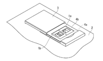
図1は、本実施形態の情報コンセント1a,1bを机の天板2に埋め込んだ例を示す。机の天板2には、化粧プレート4bで覆われた取付け具4aが取り付けられる。情報コンセント1a,1bは、取付け具4aに並べて取り付けられる。一方の情報コンセント1aは、LANケーブルのモジュラープラグが差込み可能なLAN用の情報コンセントである。他方の情報コンセント1bは、USBケーブルの端子が差込み可能なUSB用の情報コンセントである。情報コンセントの個数は1、2、3等適宜設定することができ、情報コンセント1a,1bの用途はLAN用、USB用、電話用、映像用等適宜設定することができる。   FIG. 1 shows an example in which the information outlets 1a and 1b of the present embodiment are embedded in a table top 2 of a desk. A fixture 4a covered with a decorative plate 4b is attached to the top 2 of the desk. The information outlets 1a and 1b are mounted side by side on the fixture 4a. One information outlet 1a is an information outlet for LAN into which a modular plug of a LAN cable can be inserted. The other information outlet 1b is a USB information outlet into which a USB cable terminal can be inserted. The number of information outlets can be set as appropriate, such as 1, 2, 3, etc., and the usage of the information outlets 1a, 1b can be set as appropriate for LAN, USB, telephone, video, and the like.

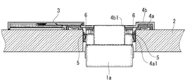
図2は、机の天板2に取り付けられる取付け具4aの断面図を示す。取付け具4aは、情報コンセント1a,1bを取り付けるための取付け枠4a1を備える。この取付け枠4a1は、埋込形配線器具用の取付け枠(例えばJIS C 8375で規格化された大角形連用配線器具の取付け枠)であり、天板2に開けた孔内に配置される。取付け枠4a1に情報コンセント1aを取り付ける際は、取付け枠4a1の下方から情報コンセント1aを挿入し、情報コンセント1aの左右の突起6(図3も参照)を取付け枠4a1の左右の係合孔5に係合させる。取付け枠4a1は、樹脂製であり、突起6を挿入できるように可撓性を持つ。情報コンセント1aを取り外すときは、天板2の上方から挿入した工具で取付け枠4a1を撓ませ、情報コンセント1aの突起6と取付け枠4a1の係合孔5との係合を外す。   FIG. 2 shows a cross-sectional view of the fixture 4a attached to the table top 2 of the desk. The attachment 4a includes an attachment frame 4a1 for attaching the information outlets 1a and 1b. The mounting frame 4a1 is a mounting frame for an embedded wiring device (for example, a mounting frame for a large-angle continuous wiring device standardized by JIS C 8375), and is disposed in a hole formed in the top plate 2. When the information outlet 1a is attached to the attachment frame 4a1, the information outlet 1a is inserted from below the attachment frame 4a1, and the left and right protrusions 6 (see also FIG. 3) of the information outlet 1a are inserted into the left and right engagement holes 5 of the attachment frame 4a1. Engage with. The attachment frame 4a1 is made of resin and has flexibility so that the protrusion 6 can be inserted. When removing the information outlet 1a, the mounting frame 4a1 is bent with a tool inserted from above the top plate 2, and the projection 6 of the information outlet 1a and the engagement hole 5 of the mounting frame 4a1 are disengaged.

取付け具4aは、化粧プレート4bで覆われる。化粧プレート4bには、情報コンセント1a,1bの上面の接続口を露出させる開口4b1が開けられる。化粧プレート4bには、化粧プレート4bの開口4b1を開閉する蓋3がスライド可能に設けられる。   The attachment 4a is covered with a decorative plate 4b. The decorative plate 4b is provided with an opening 4b1 that exposes the connection port on the upper surface of the information outlets 1a and 1b. The decorative plate 4b is slidably provided with a lid 3 that opens and closes the opening 4b1 of the decorative plate 4b.

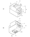
図3は、本実施形態の情報コンセント1aの外観斜視図(図3(a)は上面側斜視図、図3(b)は下面側斜視図)を示す。図4は、本実施形態の情報コンセント1aの分解斜視図を示す。11はカバー、13はケース、12はモジュラーとしての中継コネクタである。カバー11は取付け枠4a1に着脱可能に取り付けられる。ケース13はカバー11に着脱可能に取り付けられる。カバー11とケース13とが情報コンセント用器体10(以下、単に器体10という)を構成する。器体10と中継コネクタ12とが、情報コンセント1aを構成する。   FIG. 3 is an external perspective view of the information outlet 1a of this embodiment (FIG. 3A is a top perspective view, and FIG. 3B is a bottom perspective view). FIG. 4 shows an exploded perspective view of the information outlet 1a of the present embodiment. 11 is a cover, 13 is a case, and 12 is a relay connector as a modular. The cover 11 is detachably attached to the attachment frame 4a1. The case 13 is detachably attached to the cover 11. The cover 11 and the case 13 constitute an information outlet container 10 (hereinafter simply referred to as the container 10). The container 10 and the relay connector 12 constitute an information outlet 1a.

なお、以下において、説明の便宜上、図4の上下、左右、前後の各方向を用いて情報コンセント1aの構成を説明する。もちろん、情報コンセント1aの配置は、このような配置に限られるもではない。   In the following, for the convenience of explanation, the configuration of the information outlet 1a will be described using the up / down, left / right, and front / rear directions of FIG. Of course, the arrangement of the information outlet 1a is not limited to such an arrangement.

図3(a)(b)に示すように、器体10は、横長直方体状の箱体であり、その上面及び下面に略四角形の開口20c1,13c1を有する。器体10の上面の開口20c1には、中継コネクタ12の第1接続口12aが露出する。器体10の下面の開口13c1には、中継コネクタ12の第2接続口12bが露出する。中継コネクタ12の第1接続口12aには、机の上面(造営面)よりも上側に配線される第1信号線(例えば4対8芯の信号線)の第1モジュラープラグが差し込まれる。第2接続口12bには、造営面よりも下側に配線される第2信号線(例えば4対8芯の信号線)の第2モジュラープラグが差し込まれる。   As shown in FIGS. 3 (a) and 3 (b), the container body 10 is a horizontally long rectangular box, and has substantially rectangular openings 20c1 and 13c1 on the upper and lower surfaces thereof. The first connection port 12 a of the relay connector 12 is exposed in the opening 20 c 1 on the upper surface of the container body 10. The second connection port 12b of the relay connector 12 is exposed in the opening 13c1 on the lower surface of the vessel body 10. A first modular plug of a first signal line (for example, a signal line of 4 to 8 cores) wired above the upper surface (construction surface) of the desk is inserted into the first connection port 12a of the relay connector 12. A second modular plug of a second signal line (for example, a 4-to-8-core signal line) wired below the construction surface is inserted into the second connection port 12b.

図4に示すように、カバー11は、横長直方体状で左右の肩部を有する蓋体20と、蓋体20の前後方向に対向する一対の側面パネル20aそれぞれに一体に形成される第1フック21a,21b及び第2フック22a,22b(図5(b)参照)と、蓋体20の一対の肩部20bそれぞれに一体に形成されるケースフック23と、を備える。第1フック21a,21b、第2フック22a,22b及びケースフック23は可撓性を持つ。   As shown in FIG. 4, the cover 11 is a horizontally long rectangular parallelepiped lid 20 having left and right shoulders, and a first hook formed integrally with each of the pair of side panels 20 a facing the front-rear direction of the lid 20. 21a, 21b and second hooks 22a, 22b (see FIG. 5B) and a case hook 23 formed integrally with each of the pair of shoulder portions 20b of the lid body 20. The first hooks 21a and 21b, the second hooks 22a and 22b, and the case hook 23 are flexible.

第1フック21a,21bと第2フック22a,22bは、CAT5e、CAT6等の規格が異なって上下方向(器体10の奥行き方向)の長さが変わる2種類の中継コネクタ12,14(図10、図11参照)をカバー11に取り付けるために用いられる。第2フック22a,22bの上下方向の長さは、第1フック21a,21bの上下方向の長さよりも長い。ここで、第1フック21a,21b及び第2フック22a,22bの上下方向の長さとは、第1フック21a,21b及び第2フック22a,22bの、側面パネル20aから突出する部分の長さである。第1フック21a,21bは、上下方向の長さが短い中継コネクタ12(図10参照)をカバー11に取り付けるために用いられる。第2フック22a,22bは、上下方向の長さが長い中継コネクタ14(図11参照)をカバー11に取り付けるために用いられる。   The first hooks 21a, 21b and the second hooks 22a, 22b have two types of relay connectors 12, 14 (FIG. 10) having different standards such as CAT5e, CAT6, etc. and changing the length in the vertical direction (depth direction of the body 10). , See FIG. 11). The vertical lengths of the second hooks 22a and 22b are longer than the vertical lengths of the first hooks 21a and 21b. Here, the vertical lengths of the first hooks 21a and 21b and the second hooks 22a and 22b are the lengths of the portions of the first hooks 21a and 21b and the second hooks 22a and 22b that protrude from the side panel 20a. is there. The first hooks 21 a and 21 b are used for attaching the relay connector 12 (see FIG. 10) having a short vertical length to the cover 11. The second hooks 22 a and 22 b are used for attaching the relay connector 14 (see FIG. 11) having a long vertical length to the cover 11.

中継コネクタ12は、縦長正方形筒状である。中継コネクタ12は、その上面に第1接続口12aを有し、その下面に第2接続口12b(図3(b)参照)を有する。第1接続口12aには、第1モジュラープラグの例えば8極の接触子に接触する例えば8極の接触子が設けられる。第2接続口12bには、第2モジュラープラグの例えば8極の接触子に接触する例えば8極の接触子が設けられる。第1接続口12aの接触子と第2接続口12bの接触子とは、図示しない導電部材によって電気的に接続される。中継コネクタ14(図11参照)は、中継コネクタ12よりも上下方向に長い他、中継コネクタ12と略同様の構成である。中継コネクタ12,14は公知のものであるので、これ以上の詳しい説明を省略する。   The relay connector 12 has a vertically long square cylindrical shape. The relay connector 12 has a first connection port 12a on its upper surface and a second connection port 12b (see FIG. 3B) on its lower surface. The first connection port 12a is provided with, for example, an 8-pole contact that contacts the 8-pole contact of the first modular plug. The second connection port 12b is provided with, for example, an 8-pole contact that contacts the 8-pole contact of the second modular plug. The contact of the first connection port 12a and the contact of the second connection port 12b are electrically connected by a conductive member (not shown). The relay connector 14 (see FIG. 11) is substantially the same as the relay connector 12 except that it is longer in the vertical direction than the relay connector 12. Since the relay connectors 12 and 14 are publicly known, further detailed description is omitted.

ケース13は、横長直方体状の箱体である。ケース13の側面パネル13bには、左右方向に突出する突起27が設けられる。カバー11の下面にケース13の上面を突き合わせると、ケース13の突起27がカバー11のケースフック23の係合孔23aに係合して、ケース13がカバー11に取り付けられる。ケース13を取り外すときは、ケースフック23を撓ませ、ケースフック23の係合孔23aとケース13の突起27との係合を外す。   The case 13 is a horizontally long rectangular box. The side panel 13b of the case 13 is provided with a protrusion 27 protruding in the left-right direction. When the upper surface of the case 13 is abutted against the lower surface of the cover 11, the protrusion 27 of the case 13 engages with the engagement hole 23 a of the case hook 23 of the cover 11, and the case 13 is attached to the cover 11. When removing the case 13, the case hook 23 is bent to disengage the engagement hole 23 a of the case hook 23 from the protrusion 27 of the case 13.

カバー11の詳細な構造は、以下のとおりである。図5(a)はカバー11の上面側斜視図を示し、図5(b)はカバー11の下面側端図を示す。カバー11の蓋体20の上面パネル20cは、肩部20bよりも上方に突出する。上面パネル20cには、第1信号線の第1モジュラープラグが通過可能な開口20c1が形成される。肩部20bには、左右方向に突出する一対の突起6が設けられる。また、肩部20bには、左右方向に向かって開口する溝状の穴8が設けられる。突起6は、合成樹脂製の取付け枠4a1にカバー11を取り付けるのに用いられる。溝状の穴8は、金属製の取付け枠(図示せず)にカバー11を取り付けるのに用いられる。   The detailed structure of the cover 11 is as follows. 5A is a perspective view of the upper surface side of the cover 11, and FIG. 5B is an end view of the lower surface side of the cover 11. The top panel 20c of the lid 20 of the cover 11 projects upward from the shoulder 20b. The top panel 20c is formed with an opening 20c1 through which the first modular plug of the first signal line can pass. The shoulder portion 20b is provided with a pair of protrusions 6 protruding in the left-right direction. The shoulder 20b is provided with a groove-shaped hole 8 that opens in the left-right direction. The protrusion 6 is used to attach the cover 11 to the synthetic resin attachment frame 4a1. The groove-shaped hole 8 is used to attach the cover 11 to a metal attachment frame (not shown).

蓋体20の一方の側面パネル20aの内面には、第1フック21a及び第2フック22aが一体に形成される。第1フック21a及び第2フック22aは、上面パネル20cから下方に向かって延び、側面パネル20aに一体に形成される部分と、側面パネル20aから下方に突出する部分と、を有する。第1フック21aの内面及び第2フック22aの内面は、第1フック21a及び第2フック22aの厚さ分、側面パネル20aの内面よりも内方に突出する。上記のように、第2フック22aの、側面パネル20aから突出する部分の長さは、第1フック21aの、側面パネル20aから突出する部分の長さよりも長い。   A first hook 21 a and a second hook 22 a are integrally formed on the inner surface of one side panel 20 a of the lid 20. The first hook 21a and the second hook 22a have a portion that extends downward from the top panel 20c and is formed integrally with the side panel 20a, and a portion that projects downward from the side panel 20a. The inner surface of the first hook 21a and the inner surface of the second hook 22a protrude inward from the inner surface of the side panel 20a by the thickness of the first hook 21a and the second hook 22a. As described above, the length of the portion of the second hook 22a protruding from the side panel 20a is longer than the length of the portion of the first hook 21a protruding from the side panel 20a.

第1フック21aの先端部には、内方に向かって突出する断面三角形状の突起からなる爪31が一体に形成される。上下方向の長さが短い中継コネクタ12(以下、第1中継コネクタ12という)は、第1フック21aの爪31と上面パネル20cとの間に挟まれて固定される。第2フック22aの先端部にも、内方に向かって突出する断面三角形状の突起からなる爪32が一体に形成される。上下方向の長さが長い中継コネクタ14(以下、第2中継コネクタ14という)は、第2フック22aの爪32と上面パネル20cとの間に挟まれて固定される。第1中継コネクタ12と第2中継コネクタ14とは規格が異なる。例えば第1中継コネクタ12はCAT5e対応の中継コネクタであり、第2中継コネクタ14はCAT6a対応の中継コネクタである。   At the tip of the first hook 21a, a claw 31 made of a protrusion having a triangular cross section protruding inward is integrally formed. The relay connector 12 having a short vertical length (hereinafter referred to as the first relay connector 12) is fixed by being sandwiched between the claw 31 of the first hook 21a and the upper panel 20c. A claw 32 made of a protrusion having a triangular cross-section projecting inward is also integrally formed at the tip of the second hook 22a. The relay connector 14 having a long length in the vertical direction (hereinafter referred to as the second relay connector 14) is sandwiched and fixed between the claw 32 of the second hook 22a and the top panel 20c. The first relay connector 12 and the second relay connector 14 have different standards. For example, the first relay connector 12 is a relay connector compatible with CAT5e, and the second relay connector 14 is a relay connector compatible with CAT6a.

蓋体20の他方の側面パネル20aの内面にも、第1フック21bと第2フック22bとが一体に形成される。第1フック21bの形状は、第1フック21aと同一である。第2フック22bの形状は、第2フック22aと同一である。合計4つの第1フック21a,21bと第2フック22a,22bとは、互い違いに配置される。すなわち、開口20c1を挟んだ一方側(一方の側面パネル20a側)の第1フック21aと開口20c1を挟んだ他方側(他方の側面パネル20a側)の第2フック22bとが向かい合い、一方の側面パネル20a側の第2フック22aと他方の側面パネル20a側の第1フック21bとが向かい合う。   A first hook 21b and a second hook 22b are also integrally formed on the inner surface of the other side panel 20a of the lid 20. The shape of the first hook 21b is the same as that of the first hook 21a. The shape of the second hook 22b is the same as that of the second hook 22a. A total of four first hooks 21a, 21b and second hooks 22a, 22b are alternately arranged. That is, the first hook 21a on the one side (one side panel 20a side) sandwiching the opening 20c1 and the second hook 22b on the other side (the other side panel 20a side) sandwiching the opening 20c1 face each other. The second hook 22a on the panel 20a side faces the first hook 21b on the other side panel 20a side.

蓋体20の側面パネル20aそれぞれの内面には、リブ状の一対の突起34が一体に形成される。突起34、第1フック21a,21b及び第2フック22a,22bによって、中継コネクタ12,14を収容する収容部が画定される。第1フック21a,21bと第2フック22a,22bとを互い違いに配置することで、収容部に収容される中継コネクタ12,14を安定して保持することができる。   A pair of rib-shaped protrusions 34 are integrally formed on the inner surface of each side panel 20a of the lid 20. The projection 34, the first hooks 21a and 21b, and the second hooks 22a and 22b define an accommodation portion that accommodates the relay connectors 12 and 14. By arranging the first hooks 21a and 21b and the second hooks 22a and 22b alternately, the relay connectors 12 and 14 accommodated in the accommodating portion can be stably held.

ケース13の詳細な構造は、以下のとおりである。図6(a)はケース13の上面側斜視図を示し、図6(b)はケース13の下面側端図を示す。ケース13の下面パネル13cには、第2信号線の第2モジュラープラグが通過可能な開口13c1が形成される。ケース13の上端の4つの角部には、断面L字状の嵌合突起33が一体に形成される。嵌合突起33が蓋体20の内面に嵌まることで、ケース13がカバー11に位置決めされる。   The detailed structure of the case 13 is as follows. 6A shows a top perspective view of the case 13, and FIG. 6B shows a bottom end view of the case 13. As shown in FIG. The lower panel 13c of the case 13 is formed with an opening 13c1 through which the second modular plug of the second signal line can pass. At the four corners at the upper end of the case 13, fitting projections 33 having an L-shaped cross section are integrally formed. The case 13 is positioned on the cover 11 by fitting the fitting protrusion 33 on the inner surface of the lid 20.

ケース13の側面パネル13bの外面には、ケースフック23の係合孔23aに係合する突起27が形成される。ケース13の側面パネル13aそれぞれの内面には、リブ状の一対の突起35が一体に形成される。突起35、側面パネル13aによって、中継コネクタ12,14の下半分を収容する収容部が画定される。ケース13の側面パネル13aの内面のうち、第2フック22a,22bに対向する部分には、凸部として、下面パネル13cに近づくにしたがって高さが高くなる傾斜面36が形成される。   On the outer surface of the side panel 13 b of the case 13, a protrusion 27 that engages with the engagement hole 23 a of the case hook 23 is formed. A pair of rib-shaped projections 35 are integrally formed on the inner surface of each of the side panels 13a of the case 13. The projection 35 and the side panel 13a define a housing portion that houses the lower half of the relay connectors 12 and 14. Of the inner surface of the side panel 13 a of the case 13, an inclined surface 36 is formed on the portion facing the second hooks 22 a, 22 b as a convex portion that increases in height as it approaches the lower panel 13 c.

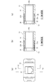
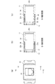
傾斜面36について詳述する。図7は、中継コネクタ12,14を組み込んでいない器体10の詳細図を示す。図7(b)(c)に示すように、ケース13の側面パネル13aの内面のうち、第2フック22a,22bに対向する部分は傾斜面36に形成される。このため、第2フック22a,22bの先端部と傾斜面36との間には殆ど隙間が無く、第2フック22a,22bは傾斜面36側に撓むのが防止される。一方、ケース13の側面パネル13aの内面のうち、第1フック21a,21bに対向する部分37(図6(a)参照)は、第1フック21a,21bと平行な平面に形成される。この部分37と第1フック21a,21bとの間には、第1フック21a,21bの長さ方向に略一定の隙間δ(図7(c)参照)が空く。   The inclined surface 36 will be described in detail. FIG. 7 shows a detailed view of the container 10 in which the relay connectors 12 and 14 are not incorporated. As shown in FIGS. 7B and 7C, a portion of the inner surface of the side panel 13 a of the case 13 that faces the second hooks 22 a and 22 b is formed on the inclined surface 36. For this reason, there is almost no gap between the tip portions of the second hooks 22a and 22b and the inclined surface 36, and the second hooks 22a and 22b are prevented from being bent toward the inclined surface 36 side. On the other hand, of the inner surface of the side panel 13a of the case 13, a portion 37 (see FIG. 6A) facing the first hooks 21a and 21b is formed in a plane parallel to the first hooks 21a and 21b. Between this portion 37 and the first hooks 21a and 21b, there is a substantially constant gap δ (see FIG. 7C) in the length direction of the first hooks 21a and 21b.

図8は、第1中継コネクタ12を組み込んだ器体10の詳細図を示す。第1中継コネクタ12を器体10に組み込んだとき、第1中継コネクタ12は、第1フック21a,21bの爪31とカバー11の上面パネル20cとの間に挟まれて固定される。このとき、第1フック21a,21bと第2フック22a,22bとはいずれも閉じている(言い換えれば、撓んでいないか、略撓んでいない)。第1中継コネクタ12に無理な力がかかり、第1フック21a,21bが開いて第1フック21a,21bの爪31と第1中継コネクタ12との係合が外れたとき、第2フック22a,22bの爪32と第1中継コネクタ12とが係合するようになる。第2フック22a,22bは傾斜面36によって開くのが防止されているので、第1中継コネクタ12が第2フック22a,22bから抜けるのを防止できる。   FIG. 8 shows a detailed view of the vessel body 10 incorporating the first relay connector 12. When the first relay connector 12 is incorporated into the container body 10, the first relay connector 12 is sandwiched and fixed between the claws 31 of the first hooks 21 a and 21 b and the upper panel 20 c of the cover 11. At this time, the first hooks 21a and 21b and the second hooks 22a and 22b are all closed (in other words, they are not bent or not substantially bent). When an excessive force is applied to the first relay connector 12, the first hooks 21a and 21b are opened, and the claws 31 of the first hooks 21a and 21b are disengaged from the first relay connector 12, the second hooks 22a and The claw 32 of 22b and the 1st relay connector 12 come to engage. Since the second hooks 22a and 22b are prevented from opening by the inclined surface 36, the first relay connector 12 can be prevented from coming off from the second hooks 22a and 22b.

図9は、第2中継コネクタ14を組み込んだ器体10の詳細図を示す。第2中継コネクタ14を器体10に組み込んだとき、第2中継コネクタ14は第2フック22a,22bの爪32とカバー11の上面パネル20cとの間に挟まれて固定される。このとき、第2フック22a,22bは閉じているが、第1フック21a,21bは、その爪31が第2中継コネクタ14の側面に当たるので開いている。第1フック21a,21bとケース13の側面パネル13aの内面37との間には、隙間δ(図7(c)参照)が空いていて、第1フック21a,21bの開きを許容するので、第1フック21a,21bが開いていても、ケース13をカバー11に取り付けることができる。第2中継コネクタ14に無理な力がかかり、第2フック22a,22bが開こうとしても、傾斜面36によって第2フック22a,22bの開きが防止されているので、第2中継コネクタ14が第2フック22a,22bから抜けるのを防止できる。   FIG. 9 shows a detailed view of the container 10 incorporating the second relay connector 14. When the second relay connector 14 is incorporated into the container body 10, the second relay connector 14 is sandwiched and fixed between the claws 32 of the second hooks 22 a and 22 b and the top panel 20 c of the cover 11. At this time, the second hooks 22 a and 22 b are closed, but the first hooks 21 a and 21 b are open because their claws 31 come into contact with the side surface of the second relay connector 14. Between the first hooks 21a, 21b and the inner surface 37 of the side panel 13a of the case 13, there is a gap δ (see FIG. 7C), and the first hooks 21a, 21b are allowed to open. Even when the first hooks 21 a and 21 b are open, the case 13 can be attached to the cover 11. Even if an excessive force is applied to the second relay connector 14 to open the second hooks 22a and 22b, the inclined surfaces 36 prevent the second hooks 22a and 22b from being opened. It is possible to prevent the hooks 22a and 22b from coming off.

図10は、第1中継コネクタ12を器体10に組み込むときの工程図を示す。第1フック21aと第2フック22bとの間及び第1フック21bと第2フック22aとの間に第1中継コネクタ12を差し込むと、第1フック21a,21b及び第2フック22a,22bが外側に開く。図10のS2,S3に示すように、第1中継コネクタ12をカバー11の上面パネル20cに当たるまで差し込むと、第1フック21a,21b及び第2フック22a,22bが閉じ、第1中継コネクタ12が第1フック21a,21bの爪31と上面パネル20cとの間に挟まれてカバー11に固定される。図10のS4に示すように、ケース13をカバー11に取り付ければ、第1中継コネクタ12が組み込まれたLANケーブル用の情報コンセント1aが完成する。   FIG. 10 is a process diagram when the first relay connector 12 is incorporated into the container 10. When the first relay connector 12 is inserted between the first hook 21a and the second hook 22b and between the first hook 21b and the second hook 22a, the first hooks 21a and 21b and the second hooks 22a and 22b are outside. Open to. As shown in S2 and S3 in FIG. 10, when the first relay connector 12 is inserted until it contacts the top panel 20c of the cover 11, the first hooks 21a and 21b and the second hooks 22a and 22b are closed, and the first relay connector 12 is It is sandwiched between the claws 31 of the first hooks 21 a and 21 b and the upper panel 20 c and is fixed to the cover 11. As shown in S4 of FIG. 10, when the case 13 is attached to the cover 11, the information outlet 1a for the LAN cable incorporating the first relay connector 12 is completed.

図11は、第2中継コネクタ14を器体10に組み込むときの工程図を示す。第1フック21aと第2フック22bとの間及び第1フック21bと第2フック22aとの間に第2中継コネクタ14を差し込むと、第1フック21a,21b及び第2フック22a,22bが外側に開く。図11のS2,S3に示すように、第2中継コネクタ14をカバー11の上面パネル20cに当たるまで差し込むと、第1フック21a,21bは外側に開いたままであるが、第2フック22a,22bは閉じる。第2中継コネクタ14は、第2フック22a,22bの爪32と上面パネル20cとの間に挟まれてカバー11に固定される。第1フック21a,21bとケース13の側面パネル13aの内面37との間には、第1フック21a,21bの開きを許容する隙間δが設けられるので、図11のS4に示すように、第1フック21a,21bが開いていても、ケース13をカバー11に取り付けることができる。   FIG. 11 is a process diagram when the second relay connector 14 is incorporated into the container 10. When the second relay connector 14 is inserted between the first hook 21a and the second hook 22b and between the first hook 21b and the second hook 22a, the first hook 21a, 21b and the second hook 22a, 22b are outside. Open to. As shown in S2 and S3 of FIG. 11, when the second relay connector 14 is inserted until it contacts the top panel 20c of the cover 11, the first hooks 21a and 21b remain open outward, but the second hooks 22a and 22b close up. The second relay connector 14 is fixed to the cover 11 by being sandwiched between the claws 32 of the second hooks 22a and 22b and the top panel 20c. A gap δ is provided between the first hooks 21a and 21b and the inner surface 37 of the side panel 13a of the case 13 to allow the opening of the first hooks 21a and 21b. As shown in S4 of FIG. The case 13 can be attached to the cover 11 even when the one hooks 21a and 21b are open.

図12は、USBケーブルのプラグを器体10に組み込むときの工程図を示す。器体10には、USBケーブルのプラグ41を組み込むことも可能である。この場合、図12のS1、S2に示すように、器体10とプラグ41との間にこれらの間の隙間を埋めてプラグ41を保持するホルダ42を介在させる。ホルダ42は、2分割された分割ホルダ42a,42bを組み合わせてなる。分割ホルダ42aと分割ホルダ42bとは、同一の形状である。一方の分割ホルダ42aのフック43を他方の分割ホルダ42bの係合孔44に係合させて、分割ホルダ42aと分割ホルダ42bとを結合させる。   FIG. 12 shows a process diagram when the plug of the USB cable is incorporated into the container 10. It is also possible to incorporate a USB cable plug 41 into the body 10. In this case, as shown in S <b> 1 and S <b> 2 of FIG. 12, a holder 42 that holds the plug 41 by interposing a gap between the container 10 and the plug 41 is interposed. The holder 42 is formed by combining two divided holders 42a and 42b. The split holder 42a and the split holder 42b have the same shape. The hook 43 of one split holder 42a is engaged with the engagement hole 44 of the other split holder 42b, and the split holder 42a and the split holder 42b are coupled.

図13は、分割ホルダ42aの正面図を示す。分割ホルダ42aには、プラグ41の形状に合わせた収容凹部45が形成される。また、分割ホルダ42aには、収容凹部45の壁面を構成するS字状の板ばね部46が設けられる。板ばね部46を設けることによって、プラグ41の寸法の変化に対応することができ、プラグ41をホルダ42内に安定して保持できる。   FIG. 13 shows a front view of the split holder 42a. The split holder 42 a is formed with an accommodation recess 45 that matches the shape of the plug 41. The split holder 42 a is provided with an S-shaped leaf spring portion 46 that constitutes the wall surface of the housing recess 45. By providing the leaf spring portion 46, it is possible to cope with a change in the dimension of the plug 41, and the plug 41 can be stably held in the holder.

図12のS1、S2に示すように、分割ホルダ42a,42b間にプラグ41を挟み、分割ホルダ42a,42bを互いに結合させた後、図12のS3に示すように、ホルダ42をカバー11に差し込む。このとき、カバー11の第1フック21a,21bの爪31がホルダ42の横長突起47に係合する。ホルダ42は、第1フック21a,21bの爪31とカバー11の上面パネル20cとの間に挟まれてカバー11に固定される。図12のS3に示すように、ケース13をカバー11に取り付ければ、USBケーブル用の情報コンセント1bが完成する。   As shown in S1 and S2 of FIG. 12, after the plug 41 is sandwiched between the divided holders 42a and 42b and the divided holders 42a and 42b are coupled to each other, the holder 42 is attached to the cover 11 as shown in S3 of FIG. Plug in. At this time, the claws 31 of the first hooks 21 a and 21 b of the cover 11 are engaged with the horizontally long protrusions 47 of the holder 42. The holder 42 is sandwiched between the claws 31 of the first hooks 21 a and 21 b and the top panel 20 c of the cover 11 and is fixed to the cover 11. As shown in S3 of FIG. 12, when the case 13 is attached to the cover 11, the information outlet 1b for the USB cable is completed.

なお、本発明は上記実施形態に具現化されるのに限られることはなく、本発明の要旨を変更しない範囲で様々な実施形態に変更できる。   Note that the present invention is not limited to the embodiment described above, and can be modified to various embodiments without departing from the gist of the present invention.

上記実施形態では、情報コンセントを机の天板に埋め込んでいるが、情報コンセントを建築物の壁面に埋め込むこともできる。この場合、取付け枠は、建築物の壁面に埋め込まれたスイッチボックスに取り付けられる。   In the above embodiment, the information outlet is embedded in the top of the desk, but the information outlet can also be embedded in the wall surface of the building. In this case, the attachment frame is attached to a switch box embedded in the wall surface of the building.

上記実施形態では、モジュラーの接続口を開閉する蓋を机の天板の化粧プレートに設けているが、モジュラーの接続口を開閉する扉をカバーに設けることもできる。   In the above embodiment, the cover for opening and closing the modular connection port is provided on the decorative plate of the desk top plate, but a door for opening and closing the modular connection port may be provided on the cover.

上記実施形態では、モジュラーが中継コネクタである例を説明したが、モジュラーにはその後部に信号線が圧接接続される端子を有するものを用いることもできる。   In the above-described embodiment, an example in which the modular is a relay connector has been described. However, a modular having a terminal to which a signal line is press-connected can be used.

上記実施形態では、第1中継コネクタ(第1モジュラー)と第2中継コネクタ(第2モジュラー)との上下方向(器体の奥行き方向)の長さが異なっているが、第1中継コネクタ(第1モジュラー)と第2中継コネクタ(第2モジュラー)との大きさ、すなわち左右方向の幅、前後方向の高さ、上下方向の長さの少なくとも一つが異なっていればよい。   In the above embodiment, the lengths of the first relay connector (first modular) and the second relay connector (second modular) in the vertical direction (depth direction of the container) are different. 1 modular) and the second relay connector (second modular) may have different sizes, that is, at least one of the width in the left-right direction, the height in the front-rear direction, and the length in the vertical direction.

1a,1b…情報コンセント
10…情報コンセント用器体
11…カバー
12…第1中継コネクタ(第1モジュラー)
12a…第1接続口(接続口)
12b…第2接続口(接続口)
13…ケース
14…第2中継コネクタ(第2モジュラー)
20c1…開口
21a,21b…第1フック
22a,22b…第2フック
36…傾斜面(凸部)
37…ケースの内面
δ…隙間
1a, 1b ... information outlet 10 ... information outlet body 11 ... cover 12 ... first relay connector (first modular)
12a ... 1st connection port (connection port)
12b ... 2nd connection port (connection port)
13 ... Case 14 ... Second relay connector (second modular)
20c1 ... Openings 21a, 21b ... First hooks 22a, 22b ... Second hook 36 ... Inclined surface (convex portion)
37 ... Inner surface of the case δ ... Gap

Claims (7)

モジュラープラグが通過可能な開口が形成されるカバーと、
前記カバーに設けられ、可撓性を持つ第1フックと、
前記カバーに設けられ、可撓性を持つ第2フックと、を備え、
前記第1フックを用いて、モジュラープラグを差込み可能な接続口を有する第1モジュラーを前記カバーに取り付けることが可能であり、
前記第2フックを用いて、前記第1モジュラーと大きさが異なり、モジュラープラグを差込み可能な接続口を有する第2モジュラーを前記カバーに取り付けることが可能である情報コンセント用器体。
A cover in which an opening through which the modular plug can pass is formed;
A first hook that is provided on the cover and has flexibility;
A second hook provided on the cover and having flexibility,
Using the first hook, a first modular having a connection port into which a modular plug can be inserted can be attached to the cover;
An information receptacle device that can be attached to the cover by using the second hook, the second modular having a different size from the first modular and having a connection port into which a modular plug can be inserted.
前記情報コンセント用器体の奥行き方向における前記第2フックの長さが、前記奥行き方向における前記第1フックの長さよりも長く、
前記奥行き方向における前記第2モジュラーの長さが、前記奥行き方向における前記第1モジュラーの長さよりも長いことを特徴とする請求項1に記載の情報コンセント用器体。
The length of the second hook in the depth direction of the information socket body is longer than the length of the first hook in the depth direction,
2. The information receptacle device according to claim 1, wherein a length of the second modular in the depth direction is longer than a length of the first modular in the depth direction.
前記情報コンセント用器体は、前記カバーに取り付けられ、前記第1モジュラー又は前記第2モジュラーの少なくとも一部が収容されるケースを備え、
前記ケースの内面と前記第1フックとの間には、前記カバーに前記第2モジュラーを取り付けたとき、前記第1フックが前記ケースの前記内面側に撓むのを許容する隙間が設けられることを特徴とする請求項1又は2に記載の情報コンセント用器体。
The information receptacle device includes a case attached to the cover and accommodating at least a part of the first modular or the second modular,
A gap is provided between the inner surface of the case and the first hook to allow the first hook to bend toward the inner surface side of the case when the second modular is attached to the cover. The information receptacle device according to claim 1 or 2, characterized by the above.
前記ケースの前記内面には、前記第2フックが前記ケースの前記内面側に撓むのを防止する凸部が設けられることを特徴とする請求項3に記載の情報コンセント用器体。   The information receptacle device according to claim 3, wherein the inner surface of the case is provided with a convex portion that prevents the second hook from being bent toward the inner surface side of the case. 前記カバーの前記開口を挟んだ一方側と他方側に前記第1フックと前記第2フックとが設けられ、
前記一方側の前記第1フックが前記他方側の前記第2フックに向かい合い、
前記一方側の前記第2フックが前記他方側の前記第1フックに向かい合うことを特徴とする請求項1ないし4のいずれか1項に記載の情報コンセント用器体。
The first hook and the second hook are provided on one side and the other side across the opening of the cover,
The first hook on the one side faces the second hook on the other side;
5. The information receptacle device according to claim 1, wherein the second hook on the one side faces the first hook on the other side. 6.
前記第1モジュラー及び前記第2モジュラーは、第1中継コネクタ及び第2中継コネクタであることを特徴とする請求項1ないし4のいずれか1項に記載の情報コンセント用器体。   5. The information receptacle device according to claim 1, wherein the first modular and the second modular are a first relay connector and a second relay connector. 6. 請求項1ないし6のいずれか1項に記載の情報コンセント用器体と、
前記第1モジュラー又は前記第2モジュラーと、を備える情報コンセント。
An information socket device body according to any one of claims 1 to 6,
An information outlet comprising the first modular or the second modular.
JP2017041584A 2017-03-06 2017-03-06 Information outlet and information outlet Active JP6466491B2 (en)

Priority Applications (1)

Application Number Priority Date Filing Date Title
JP2017041584A JP6466491B2 (en) 2017-03-06 2017-03-06 Information outlet and information outlet

Applications Claiming Priority (1)

Application Number Priority Date Filing Date Title
JP2017041584A JP6466491B2 (en) 2017-03-06 2017-03-06 Information outlet and information outlet

Publications (2)

Publication Number Publication Date
JP2018147720A JP2018147720A (en) 2018-09-20
JP6466491B2 true JP6466491B2 (en) 2019-02-06

Family

ID=63591529

Family Applications (1)

Application Number Title Priority Date Filing Date
JP2017041584A Active JP6466491B2 (en) 2017-03-06 2017-03-06 Information outlet and information outlet

Country Status (1)

Country Link
JP (1) JP6466491B2 (en)

Families Citing this family (2)

* Cited by examiner, † Cited by third party
Publication number Priority date Publication date Assignee Title
DE102018124821A1 (en) * 2018-10-09 2020-04-09 Phoenix Contact E-Mobility Gmbh Connector part with an inlet part to be connected to a housing part
CN209448107U (en) 2018-12-21 2019-09-27 泰科电子(上海)有限公司 Supporting mechanism and electrical connector

Family Cites Families (5)

* Cited by examiner, † Cited by third party
Publication number Priority date Publication date Assignee Title
JPH10294144A (en) * 1997-04-17 1998-11-04 Murata Mach Ltd Modular jack and plug therefor
JP3473428B2 (en) * 1998-08-26 2003-12-02 松下電工株式会社 Information outlet
JP2000148296A (en) * 1998-11-12 2000-05-26 Funai Electric Co Ltd Electronic equipment casing containing modular jack
JP2004171883A (en) * 2002-11-19 2004-06-17 Kansai Tsushin Densen Co Ltd Modular junction receptacle
JP2006031988A (en) * 2004-07-13 2006-02-02 Matsushita Electric Ind Co Ltd Protective cover for modular connector

Also Published As

Publication number Publication date
JP2018147720A (en) 2018-09-20

Similar Documents

Publication Publication Date Title
JP6230471B2 (en) connector
US10085355B2 (en) Housing mountable on a mounting rail for receiving an electronics module
JP6368504B2 (en) Electrical connector
JP6878125B2 (en) Patch panel
US9509079B2 (en) Assembling structure of electronic component, electrical junction box, and electronic component
CN112470348B (en) Connector and connector device
JP6466491B2 (en) Information outlet and information outlet
JP2011222157A (en) Electric connector
JP2015084277A (en) Connector structure and wire harness
JP6315339B2 (en) connector
JP2014207150A (en) Assembling structure of electronic component, and electronic component
JP6804107B2 (en) Anti-rattle structure, electronic component module, electrical junction box, and wire harness
JP4079155B2 (en) Multimedia outlet
EP3002830B1 (en) Multi-position mechanism for socket-outlets
US10186789B1 (en) Keyed cable and connector system
JP6884631B2 (en) Patch panel
JP5678335B2 (en) Modular jack outlet
JP5363952B2 (en) Electrical equipment with incorrect connection prevention mechanism
JP2015062191A (en) Connector
JP5650913B2 (en) Retaining plug
JP7240307B2 (en) Cover structure in electronic equipment
JP2000223189A (en) Electrical connector
JP4151535B2 (en) Exposed modular jack
JP6034276B2 (en) Connector structure
JP2013070464A (en) Wiring device for information

Legal Events

Date Code Title Description
TRDD Decision of grant or rejection written
A977 Report on retrieval

Free format text: JAPANESE INTERMEDIATE CODE: A971007

Effective date: 20181227

A01 Written decision to grant a patent or to grant a registration (utility model)

Free format text: JAPANESE INTERMEDIATE CODE: A01

Effective date: 20190108

A61 First payment of annual fees (during grant procedure)

Free format text: JAPANESE INTERMEDIATE CODE: A61

Effective date: 20190109

R150 Certificate of patent or registration of utility model

Ref document number: 6466491

Country of ref document: JP

Free format text: JAPANESE INTERMEDIATE CODE: R150