JP6465893B2 - Shaving blade cartridge, method for manufacturing such a shaving blade cartridge, and razor having such a shaving blade cartridge - Google Patents
Shaving blade cartridge, method for manufacturing such a shaving blade cartridge, and razor having such a shaving blade cartridge Download PDFInfo
- Publication number
- JP6465893B2 JP6465893B2 JP2016541133A JP2016541133A JP6465893B2 JP 6465893 B2 JP6465893 B2 JP 6465893B2 JP 2016541133 A JP2016541133 A JP 2016541133A JP 2016541133 A JP2016541133 A JP 2016541133A JP 6465893 B2 JP6465893 B2 JP 6465893B2
- Authority
- JP
- Japan
- Prior art keywords
- housing
- holder
- rivet
- blade cartridge
- shaving blade
- Prior art date
- Legal status (The legal status is an assumption and is not a legal conclusion. Google has not performed a legal analysis and makes no representation as to the accuracy of the status listed.)
- Active
Links
Images


Classifications
-
- B—PERFORMING OPERATIONS; TRANSPORTING
- B26—HAND CUTTING TOOLS; CUTTING; SEVERING
- B26B—HAND-HELD CUTTING TOOLS NOT OTHERWISE PROVIDED FOR
- B26B21/00—Razors of the open or knife type; Safety razors or other shaving implements of the planing type; Hair-trimming devices involving a razor-blade; Equipment therefor
- B26B21/40—Details or accessories
- B26B21/4012—Housing details, e.g. for cartridges
-
- B—PERFORMING OPERATIONS; TRANSPORTING
- B26—HAND CUTTING TOOLS; CUTTING; SEVERING
- B26B—HAND-HELD CUTTING TOOLS NOT OTHERWISE PROVIDED FOR
- B26B21/00—Razors of the open or knife type; Safety razors or other shaving implements of the planing type; Hair-trimming devices involving a razor-blade; Equipment therefor
- B26B21/08—Razors of the open or knife type; Safety razors or other shaving implements of the planing type; Hair-trimming devices involving a razor-blade; Equipment therefor involving changeable blades
- B26B21/14—Safety razors with one or more blades arranged transversely to the handle
- B26B21/22—Safety razors with one or more blades arranged transversely to the handle involving several blades to be used simultaneously
- B26B21/222—Safety razors with one or more blades arranged transversely to the handle involving several blades to be used simultaneously with the blades moulded into, or attached to, a changeable unit
- B26B21/227—Safety razors with one or more blades arranged transversely to the handle involving several blades to be used simultaneously with the blades moulded into, or attached to, a changeable unit with blades being resiliently mounted in the changeable unit
-
- B—PERFORMING OPERATIONS; TRANSPORTING
- B26—HAND CUTTING TOOLS; CUTTING; SEVERING
- B26B—HAND-HELD CUTTING TOOLS NOT OTHERWISE PROVIDED FOR
- B26B21/00—Razors of the open or knife type; Safety razors or other shaving implements of the planing type; Hair-trimming devices involving a razor-blade; Equipment therefor
- B26B21/40—Details or accessories
- B26B21/4068—Mounting devices; Manufacture of razors or cartridges
-
- B—PERFORMING OPERATIONS; TRANSPORTING
- B26—HAND CUTTING TOOLS; CUTTING; SEVERING
- B26B—HAND-HELD CUTTING TOOLS NOT OTHERWISE PROVIDED FOR
- B26B21/00—Razors of the open or knife type; Safety razors or other shaving implements of the planing type; Hair-trimming devices involving a razor-blade; Equipment therefor
- B26B21/40—Details or accessories
- B26B21/44—Means integral with, or attached to, the razor for storing shaving-cream, styptic, or the like
- B26B21/443—Lubricating strips attached to the razor head
Description
本発明の実施形態は、シェービング刃カートリッジと、かかるシェービング刃カートリッジを有するシェーバとに関する。 Embodiments of the present invention relate to a shaving blade cartridge and a shaver having such a shaving blade cartridge.
特に、本発明は、
- 長手方向軸に沿って延在し、上側部、上側部の反対側の底側部、および上側部と底側部との間を長手方向軸に沿って長手方向に延在する2つの長手方向側部を有するハウジングと、
- 長手方向側部間においてハウジング内に取り付けられた切り刃であって、長手方向軸に沿って延在する刃先を有する切り刃と、
- ハウジング内に切り刃を保持する保持具と
を備えるシェービング刃カートリッジに関する。
In particular, the present invention
-Two longitudinals extending along the longitudinal axis and extending longitudinally along the longitudinal axis between the upper part, the bottom part opposite the upper part, and between the upper part and the bottom part A housing having directional sides;
A cutting blade mounted in the housing between the longitudinal sides, the cutting blade having a cutting edge extending along the longitudinal axis;
-The present invention relates to a shaving blade cartridge comprising a holder for holding a cutting blade in a housing.
米国特許第4443940号は、ハウジングおよび切り刃を備えるシェービング刃カートリッジを開示している。米国特許第4443940号の第1の実施形態では、ハウジングの一部分が、切り刃を部分的に覆う。この部分により、切り刃は、ハウジング上に維持され得る。別の実施形態では、切り刃は、保持具を形成するブリッジにより維持される。保持具は、キャップ部材および部分ガード部材と共に一体的に形成され、次いでハウジング内にスナップ嵌めされる。かかる保持具は、安定的ではなく、カートリッジが組み立てられた後の刃の安全性を低下させ得る。さらに、かかる保持具の製造は、長時間にわたる恐れがあり、この組立ては、厳格な公差の適用を必要とする。 U.S. Pat. No. 4,443,940 discloses a shaving blade cartridge comprising a housing and a cutting blade. In a first embodiment of U.S. Pat. No. 4,443,940, a portion of the housing partially covers the cutting blade. This part allows the cutting edge to be maintained on the housing. In another embodiment, the cutting blade is maintained by a bridge that forms a retainer. The retainer is integrally formed with the cap member and the partial guard member and then snapped into the housing. Such a holder is not stable and may reduce the safety of the blade after the cartridge is assembled. In addition, the manufacture of such retainers can be lengthy and this assembly requires the application of strict tolerances.
また、文献EP2123409は、ハウジングおよび切り刃を有するシェービング刃カートリッジを開示している。スナップ嵌めされた保持具が、ハウジング上に切り刃を保持するために設けられる。十分な保持力を与えるために、保持具は、ハウジングの多数のエリアにてスナップ嵌めされ、特にハウジングの上側部の中間部において固定が得られる。しかし、かかる保持具は、シェービング中の作動表面を縮小させる。 Document EP2123409 also discloses a shaving blade cartridge having a housing and a cutting blade. A snap fit holder is provided to hold the cutting blade on the housing. In order to provide a sufficient holding force, the holding device is snap-fit in a number of areas of the housing, and in particular a fixation is obtained in the middle part of the upper part of the housing. However, such a holder reduces the working surface during shaving.
本発明の実施形態は、上記に論じた欠点を緩和することを目的とする。 Embodiments of the present invention aim to alleviate the drawbacks discussed above.
この目的のために、本発明の一実施形態によれば、かかるシェービング刃カートリッジは、保持具がリベットによりハウジング上に保持される点を特徴とする。 For this purpose, according to one embodiment of the invention, such a shaving blade cartridge is characterized in that the holder is held on the housing by a rivet.
これらの特徴により、ハウジングおよび保持具は、共に頑丈に接合される。実際に、リベットは、耐疲労性を有し、特にリベット組立が、例えば溶接組立よりも高い耐疲労性を有する。リベットは、低い製造コストによる設定が容易である。リベットは、目立たず好ましい外見の固定部を形成し、これはハウジングから大げさに突出しない。 Due to these features, the housing and retainer are firmly joined together. In fact, rivets have fatigue resistance, and in particular rivet assemblies have higher fatigue resistance than, for example, weld assemblies. Rivets are easy to set at low manufacturing costs. The rivet forms an inconspicuous and preferred appearance of the fixed part, which does not protrude excessively from the housing.
いくつかの実施形態では、当業者は以下の特徴のうちの1つまたは複数をさらに用い得る。
- 保持具は、ハウジングの上側部上で延在する保持具本体を備え、保持具およびハウジングは、ハウジングの上側部上で共に接合され、製造は、シェービング刃カートリッジのハウジングがハウジング上に保持具を固定するために回転される必要がないため容易である。
- ハウジングは、リベットピンを備え、保持具は、貫通穴を備え、貫通穴は、リベットピンと協働する。貫通穴とリベットピンとの協働により、保持具用の位置インジケータが形成される。
- ハウジングは、2つのリベットピンを備え、保持具は、2つの貫通穴を備え、各貫通穴は、2つのリベットピンの一方と協働し、2つのリベットピンは、刃先の前方または後方に位置する。貫通穴と協働するリベットピンにより、保持具の容易な位置決めが可能となる。
- リベットピンは、プラスチック材料を含む。プラスチック材料は、リベット固定により容易に変形する。
- ハウジングには、ガードバーが設けられており、ガードバーは、刃先の前方に位置する。
- リベットピンは、ガードに隣接して設けられる。リベットピンのこの位置により、シェービング表面(シェービング中には作動表面となる)を下げることを伴わないおよびシェービング性能を低下させることを伴わない保持が可能となる。
- ハウジングは、シェービング補助部材を備え、シェービング補助部材は、刃先の後方に位置する。
- リベットピンは、シェービング補助部材に隣接して設けられる。リベットピンの位置は、シェービング性能を低下させない。
- リベットピンおよびハウジングは一体的に形成される。製造がより容易であり、これにより耐久性が向上する。
- 保持具は、横軸に沿って延在する保持具本体を備え、横軸は、2つの自由端部を有するとともに長手方向軸を横断し、貫通穴は、2つの自由端部の一方の付近に位置し、この特徴により美的側面を与えることが可能となり、保持具に使用される材料の量を減少させることが可能となる。
- リベットピンおよびハウジングは同一材料からなり、この特徴により保持具の容易な製造が可能となる。
- 保持具は平坦である。曲げなどの保持具の形成のためのさらなるステップは不要となる。公差が向上し得る。
- ハウジングは、2つの凹部を備え、保持具は、2つのレッグと、レッグ間に延在する保持具本体とを備え、保持具本体は、横軸に沿って延在し、横軸は、長手方向軸を横切り、レッグは、2つの凹部の一方の中にそれぞれ受けられる。保持具の自由端部は、ハウジングの内部に隠される。
- 2つの凹部は、横軸および長手方向軸と交差する側軸に沿って延在し、2つの凹部は、止まり穴であり、2つの凹部は、切り刃の各側に位置する。
- シェービング刃カートリッジは、ハウジング内に刃を保持する2つの保持具を備え、2つの保持具のそれぞれおよびハウジングは、ハウジングの上側部上のリベットにより共に接合され、ホールド機能が強化される。
- 保持具本体は、溝を備え、刃先は、溝内に延在する。この特徴により、2つの切り刃間の距離の制御が改善され、ハウジングに対する切り刃の位置および配置が確保され、切り刃の横移動が軽減され得る。
- 複数の切り刃が設けられ、複数の溝が設けられ、各切り刃が、保持具の内部表面上に設けられた1つの溝と協働する。
In some embodiments, one of ordinary skill in the art may further use one or more of the following features.
The retainer comprises a retainer body extending on the upper part of the housing, the retainer and the housing are joined together on the upper part of the housing, the manufacture of the shaving blade cartridge housing being retained on the housing; It is easy because it does not need to be rotated to fix.
The housing comprises a rivet pin, the retainer comprises a through hole, which cooperates with the rivet pin; The position indicator for the holder is formed by the cooperation of the through hole and the rivet pin.
-The housing has two rivet pins, the retainer has two through holes, each through hole cooperates with one of the two rivet pins, the two rivet pins in front or behind the cutting edge To position. The rivet pin cooperating with the through hole allows easy positioning of the holder.
-Rivet pins include plastic material. Plastic materials are easily deformed by rivet fixation.
-The housing is provided with a guard bar, which is located in front of the cutting edge.
-Rivet pins are provided adjacent to the guard. This position of the rivet pin allows holding without lowering the shaving surface (which becomes the working surface during shaving) and without reducing the shaving performance.
The housing comprises a shaving aid, which is located behind the cutting edge;
-The rivet pin is provided adjacent to the shaving aid member. The position of the rivet pin does not degrade the shaving performance.
-The rivet pin and the housing are integrally formed. It is easier to manufacture and this improves durability.
The retainer comprises a retainer body extending along a transverse axis, the transverse axis having two free ends and transverse to the longitudinal axis, the through hole being one of the two free ends; Located in the vicinity, this feature makes it possible to give an aesthetic aspect and reduce the amount of material used in the holder.
-The rivet pin and the housing are made of the same material, and this feature allows easy manufacture of the retainer.
-The retainer is flat. No further steps for forming the holder, such as bending, are necessary. Tolerance can be improved.
The housing comprises two recesses, the retainer comprises two legs and a retainer body extending between the legs, the retainer body extending along the horizontal axis, Crossing the longitudinal axis, the legs are each received in one of the two recesses. The free end of the retainer is hidden inside the housing.
The two recesses extend along a lateral axis intersecting the transverse axis and the longitudinal axis, the two recesses are blind holes and the two recesses are located on each side of the cutting edge.
-The shaving blade cartridge comprises two holders holding the blade in the housing, each of the two holders and the housing being joined together by a rivet on the upper part of the housing, enhancing the holding function.
-The holder body is provided with a groove and the cutting edge extends into the groove. This feature improves the control of the distance between the two cutting edges, ensures the position and placement of the cutting edge relative to the housing, and can reduce lateral movement of the cutting edge.
-A plurality of cutting edges are provided, a plurality of grooves are provided, and each cutting edge cooperates with one groove provided on the inner surface of the holder.
また、本発明の実施形態は、シェービング刃カートリッジの製造方法に関し、この方法は、
- 長手方向軸に沿って延在し、上側部、上側部の反対側の底側部、および上側部と底側部との間で長手方向軸に沿って長手方向に延在する2つの長手方向側部を有するハウジングを用意するステップであって、切り刃が、長手方向側部間においてリベットピンを備えるハウジング内に取り付けられ、長手方向軸に沿って延在する刃先を有する、ステップと、
- 貫通穴を有する保持具を用意するステップと、
- 保持具の貫通穴内にリベットピンを配置することによりハウジングに保持具を組み付けるステップであって、リベットピンは、保持具の貫通穴から突出する自由端部を有する、ステップと、
- 保持具がハウジング内に切り刃を保持するように、リベット固定によりハウジング上に保持具を固定するステップと
を含む。
An embodiment of the present invention also relates to a method for manufacturing a shaving blade cartridge, which includes:
-Two longitudinals extending along the longitudinal axis and extending longitudinally along the longitudinal axis between the upper part, the bottom part opposite the upper part and between the upper part and the bottom part Providing a housing having directional sides, the cutting blade being mounted in a housing with rivet pins between the longitudinal sides and having a cutting edge extending along the longitudinal axis;
-Preparing a holder having a through hole;
Assembling the holder with the housing by placing a rivet pin in the through hole of the holder, the rivet pin having a free end protruding from the through hole of the holder;
Fixing the retainer on the housing by rivet fixation so that the retainer retains the cutting blade in the housing.
かかる方法は、シェービング刃カートリッジの製造を簡易化する。 Such a method simplifies the manufacture of the shaving blade cartridge.
一実施形態によれば、リベット固定によりハウジング上に保持具を固定するステップは、叩打によるリベットピンの自由端部の塑性変形によって実現される。また、リベット固定によりハウジング上に保持具を固定するステップは、リベットピンに超音波ビームを印加してリベットピンの自由端部を変形させることによっても実現され得る。この超音波溶接方法は、例えばソノトロードなどを用いて容易に実行される。 According to one embodiment, the step of fixing the holder on the housing by rivet fixing is realized by plastic deformation of the free end of the rivet pin by tapping. Further, the step of fixing the holding tool on the housing by fixing the rivet may be realized by applying an ultrasonic beam to the rivet pin to deform the free end portion of the rivet pin. This ultrasonic welding method is easily executed using, for example, sonotrode.
また、本発明の実施形態は、ハンドルおよび上述のようなシェービング刃カートリッジを備えるシェーバに関し、このシェービング刃カートリッジは、ハンドルに連結される。 Embodiments of the present invention also relate to a shaver comprising a handle and a shaving blade cartridge as described above, the shaving blade cartridge being coupled to the handle.
本発明の実施形態の他の特徴および利点は、非限定的な例として提示され添付の図面に示されるその実施形態のうちの1つの以下の説明から容易に明らかになろう。 Other features and advantages of embodiments of the present invention will be readily apparent from the following description of one of its embodiments, presented as a non-limiting example and shown in the accompanying drawings.
種々の図において、同一の参照符号は同様または類似の要素を指す。 In the various figures, the same reference signs refer to the same or analogous elements.
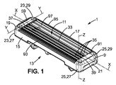
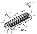
図1、図2、図4、図5A、および図5Bは、刃5がシェービング刃カートリッジ1に対してモータにより駆動されない、湿式剃刀3のシェービング刃カートリッジを示す。
1, FIG. 2, FIG. 4, FIG. 5A and FIG. 5B show a shaving blade cartridge of a wet razor 3 in which the
図11に示すように、シェービング刃カートリッジ1は、近位部分Ppと遠位部分Dpとの間においてハンドル方向に延在するハンドル7に装着され得る。ハンドル7は、シェービング刃カートリッジ1に対して枢動可能である。他の実施形態では、ハンドル7は、シェービング刃カートリッジ1に対して固定されてもよい。ハンドル方向は、曲線であっても、または1つまたは複数の直線部分を備えてもよい。シェービング刃カートリッジ1は、例えばロックアンドリリース機構によりシェーバハンドル7に解除可能に連結され得る。
As shown in FIG. 11, the
図1、図2、図4、図5A、および図5Bに示すように、シェービング刃カートリッジ1は、ハウジング9を備える。ハウジング9は、長手方向軸X-Xに沿って延在する。上面から見た場合に、ハウジング9は、矩形の全体形状を有する。しかし、いくつかの実施形態では、ハウジング9の全体形状は異なるものでもよく、例えばハウジング9は、楕円形状、正方形形状、または円形状を有することが可能である。ハウジング9は、上側部11、上側部11の反対側の底側部13、ならびに第1の長手方向側部15および第2の長手方向側部17を備える。例えば、底側部13は、ハンドル7の正面に配置されるように構成されるが、上側部11は、底側部13の反対側に配置される。上側部11および底側部13は、相互に対して平行であることが可能である。
As shown in FIGS. 1, 2, 4, 5A, and 5B, the
第1の長手方向側部15は、長手方向軸X-Xに沿って延在する。第2の長手方向側部17および第1の長手方向側部15は、相互に対面している。第2の長手方向側部17は、特に第1の長手方向側部15および第2の長手方向側部17が平坦である場合に、第1の長手方向側部15に対してほぼ平行となり得る。しかし、第1の長手方向側部15および第2の長手方向側部17は、わずかなまたは認知できる程度の逆傾斜を互いに有することも可能である。第1の長手方向側部15および第2の長手方向側部17は、湾曲表面を有することも可能である。また、第2の長手方向側部17も、長手方向軸X-Xに沿って延在する。第1の長手方向側部15および第2の長手方向側部17はそれぞれ、ハウジングの上側部11と底側部13との間を側軸Z-Zに沿って側方方向Zに延在する。第1の側部15は、この実施形態による刃先の前方または後方に位置し得る。側軸Z-Zは、長手方向軸X-Xと交差する。例えば、長手方向軸X-Xおよび側軸Z-Zは、相互に直交してもよい。
The first
また、図1、図2、および図4に最も良く示すように、ハウジング9は、横軸Y-Yに沿って、第1の長手方向側部15と第2の長手方向側部17との間で延在する第1の側方側部19および第2の側方側部21を備え得る。横軸Y-Yは、長手方向軸X-Xを横切る。例えば、横軸Y-Yは、長手方向軸X-Xに対しておよび側軸Z-Zに対して直交することが可能である。第1の側方側部19および第2の側方側部21は、上側部11と底側部13との間で側方方向Zに配置される。第1の長手方向側部15、第2の長手方向側部17、第1の側方側部19、および第2の側方側部21は、ハウジング9の外部表面を共に形成する。
In addition, as best shown in FIGS. 1, 2, and 4, the
第1の側方側部19および第2の側方側部21は共に、第1の長手方向側部15および第2の長手方向側部17の長手方向端部23、25を接合する。同様に、第1の長手方向側部15および第2の長手方向側部17は共に、第1の側方側部19および第2の側方側部21の自由端部27、29を接合する。ハウジング9は、プラスチック材料を含むことが可能である。しかし、他の材料を使用することも可能である。例えば、ハウジングは、金属材料を含むことが可能である。さらに、ハウジングは、2つ以上の異なる材料の組合せを用いて作製することが可能である。例えば、ハウジングの一部が、第1の材料で作製され得る一方で、ハウジングの他の部分が、第2の材料で作製される。
Both the first
ハウジング9は、例えばハンドル7を連結するように構成された連結機構31を底側部13に備えることが可能である。したがって、連結機構31により、ハンドル7に対するシェービング刃カートリッジ1の解除および/または装着が可能となる。
The
また、ハウジング9は、図2に示すように刃受容セクション33を備える。刃受容セクション33または刃受容エリアは、ほぼ矩形の形状を有し得る。刃受容セクション33は、ハウジング9の上側部11上に配置される。刃受容セクション33は、凹部を画成し、少なくとも1つの切り刃35を受容するように構成される。換言すれば、シェービング刃カートリッジ1は、少なくとも1つの切り刃35(以下の説明では刃とも呼ばれる)を備える。図1、図2、図4、図5A、図8、および図11に示すように、シェービング刃カートリッジは、3つの切り刃を備える。しかし、他の実施形態では、シェービング刃カートリッジ1は、4つ以上または2つ以下の切り刃35を備えることが可能である。例えば、シェービング刃カートリッジ1は、5つの切り刃を備えることが可能である。
The
切り刃35は、ハウジング9の第1の長手方向側部15と第2の長手方向側部17との間およびハウジング9の第1の側方側部19と第2の側方側部21との間の刃受容セクション33内においてハウジング9内に取り付けられる。図1、図2、および図4に示すように、各刃35は、長手方向軸X-Xに沿って長手方向に延在する。各切り刃35は、長手方向軸X-Xに沿って第1の端部37および第2の端部39を備え、第1の長手方向側部15に向かって配向される。切り刃35の第1の端部37は、ハウジング9の第1の側方側部19に向かって配向されるが、切り刃35の第2の端部39は、ハウジング9の第2の側方側部21に向かって配向される。各切り刃35は、刃先41を備える。刃先41は、長手方向軸X-Xに沿って延在する。切り刃35の刃先41は、シェービング中に毛を切断するためにハウジング9の上側部11にてアクセス可能である。
The
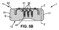
例えば、切り刃35は、図3、図5A、および図5Bに示されるものなどのL字形状である。したがって、切り刃35は、刃先部分43と、被ガイド部分45と、刃先部分43および被ガイド部分45の中間に位置する屈曲部分47とを有する。刃先部分43は、刃先部分軸に沿って延在する。有利には、全ての切り刃35の刃先部分軸が、相互に平行に位置決めされる。
For example, the
一実施形態では、各切り刃35は、図3、図5A、および図5Bに最も良く示すようにハウジング9内に自由に取り付けられる。より正確には、切り刃35は、刃受容セクション33内に可動的に取り付けられる。各切り刃35は、例えば2つの弾性フィンガにより支持される。弾性フィンガは、ハウジング9と共に単片として成形され、相互に向かっておよびハウジング9の両側方側部19、21から上方へと刃受容セクション33内に延在することが可能である。図3、図5A、および図5Bに示すように、切り刃35の被ガイド部分45は、ハウジング9に設けられたスロット53内で摺動的に案内される。例えば、切り刃35は、被ガイド部分45および屈曲部分47を備える刃支持部57上に固定された刃先41を備えることが可能である。この場合に、刃支持部57は、弾性フィンガにより担持される。
In one embodiment, each cutting
しかし、いくつかの他の実施形態では(図示せず)、刃は、例えば特許出願WO2013/050606などに記載されるような屈曲刃か、または湾曲刃であることが可能である。 However, in some other embodiments (not shown), the blades can be bent blades or curved blades as described, for example, in patent application WO2013 / 050606.
各切り刃35は、保持具59によりハウジング9内に保持される。保持具59は、リベット61によりハウジング上に保持される。リベット61は、図3で断面図にて最も良く示される。リベット61は、ハウジング9上に保持具の永続型(取外し不能型)機械固定具を形成する。
Each
図6および図7においてより具体的に示されるように、保持具61は、第1の方向D1に沿って延在する保持具本体63を備える。保持具本体63は、長さ「L」、幅「l」、および厚さ「ep」を有する。保持具の幅「l」は、好ましくはその長さ「L」に沿って殆ど一定である。他の実施形態では、保持具の幅「l」および厚さ「ep」は、可変的であることが可能である。
As shown more specifically in FIGS. 6 and 7, the
保持具本体63は、その長さに沿って第1の端部65および第2の端部67を備える。
The holder
保持具本体63は、その第1の端部65の付近に配置された第1の貫通穴69を備える。貫通穴69は、保持具本体63の第1の端部65の非ゼロ距離に位置する。貫通穴69は、例えば円形形状を有する。しかし、他の形状を与えることが可能である。例えば、貫通穴は、矩形形状、正方形形状、L字形状、または楕円形状を有してもよい。貫通穴69は、例えば保持具本体63に切削される。また、貫通穴は例えば穿孔され得る。別の実施形態では、保持具59は、貫通穴69を有して直接的に形成される。
The holder
図6および図7に示す実施形態では、保持具本体63は、その第2の端部67の付近に配置された第2の貫通穴71を備える。第2の貫通穴71は、第1の貫通穴69と同様である。しかし、いくつかの実施形態では、第2の貫通穴71は、第1の貫通穴69とは異なる形状および/または寸法を有し得る。
In the embodiment shown in FIGS. 6 and 7, the holder
図6に示すように、第1の実施形態では、保持具は、例えば保持具本体63を備えるストリップなどである。保持具59は、好ましくは平坦である。保持具59は、第1の直径D1に沿って延在する。したがって、保持具本体63の第1の端部65および第2の端部67は、保持具の第1の自由端部73および第2の自由端部75に対応する。
As shown in FIG. 6, in the first embodiment, the holder is, for example, a strip including a
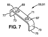
図7ならびに図4、図5A、および図5Bに開示されるものなどの別の実施形態では、保持具59は、第1のレッグ77を有する。保持具本体63は、好ましくは平坦である。また、保持具59は、第2のレッグ79を有することも可能であり、保持具本体63は、第1のレッグ77と第2のレッグ79との間で延在する。より具体的には、第1のレッグ77は、保持具本体63の第1の端部65から延在し、第2の端部79は、保持具本体63の第2の端部67から延在する。レッグ77、79は、保持具本体63に対して屈曲しており、第1の方向D1に対して著しく直交する方向に沿って延在する。例えば、保持具は一体的に形成される。保持具59のレッグは、ハウジングに設けられた対応する凹部に挿入されるように構成される。
In another embodiment, such as that disclosed in FIG. 7 and FIGS. 4, 5A, and 5B, the
例えば、図6および図7に示すものなどの保持具は、一体的に形成される。保持具は、例えば適切な金属シートなどの形成可能材料から作製され得る。しかし、他の材料が考えられ得る。別の実施形態では、保持具は、射出成形により製造することも可能である。ポリマー材料(例えば強化ポリマー材料)が、保持具を形成するために成形することが可能である。保持具は、被覆またはめっきされ得る。 For example, holders such as those shown in FIGS. 6 and 7 are integrally formed. The retainer can be made from a formable material such as a suitable metal sheet. However, other materials can be considered. In another embodiment, the retainer can be manufactured by injection molding. A polymeric material (eg, a reinforced polymeric material) can be shaped to form the retainer. The retainer can be coated or plated.
図7に示す実施形態では、保持具のレッグ77、79は、屈曲され得る。ポリマー材料(例えば強化ポリマー材料)が保持具を形成するために成形される場合には、保持具59は、その最終形状に達するまで加圧成形され得る。
In the embodiment shown in FIG. 7, the
保持具59は、ハウジング9上に取り付けられ、リベット61によりハウジングに固定されるように構成される。
The
ハウジング上における保持具の取付け位置において、保持機本体は、横軸Y-Yに沿って延在する。保持機本体63は、ハウジング9の上側部11上で延在する。より具体的には、保持具59は、切り刃35の刃先41に面して配置される。保持機本体63の第1の端部65は、第1の長手方向側部15に向かって配向されるが、保持機本体63の第2の端部67は、第2の長手方向側部17に向かって配向される。
In the attachment position of the holder on the housing, the holder body extends along the horizontal axis Y-Y. The holder
ハウジング9の上側部11は、ハウジング9の上側部11から突出するリベットピン81を備える。リベットピン81は、底側の方向とは逆の方向に、例えば側軸Z-Zに沿ってなどハウジング9の上側部11から突出する。リベットピン81は、例えばハウジング9と同一の材料を用いて作製される。例えば、ハウジング9およびリベットピン81は、一体的に形成される(単体としてまたは一体鋳造で)。しかし、いくつかの実施形態では、リベットピン81は、ハウジング9の材料とは異なる材料から作製され得る。また、リベットピン81は、例えば溶接(レーザ溶接等)または他の組立て方法などによりハウジングに組み付けられ得る。リベットピン81は、円錐形状を有し得る。この円錐形状により、射出成形からの離型が容易になる。しかし、リベットピン81は、例えば円筒形状または球形状などの他の形状を有してもよい。リベットピン81は、中空または中実であることが可能である。例えば、リベットピンは、円筒状および中空であることが可能である(ならびに加締めピンとも呼び得る)。
The
リベットピン81は、刃受容セクション33の外周部とハウジング9の長手方向側部15、17および/または側方側部19、21との間に位置する。より正確には、長手方向側部15、17は、それぞれ第1の端部23および第2の端部25を有し、側方側部19、21は、それぞれ第1の端部27および第2の端部29を有する。第1の側方側部19、21は共に、第1の長手方向側部15および第2の長手方向側部17の第1の端部23および第2の端部25を接合する。同様に、第1の長手方向側部15および第2の長手方向側部17は共に、第1の側方側部19および第2の側方側部21の第1の端部27および第2の端部29を接合する。リベットピン81は、第1の長手方向側部15および/または第2の長手方向側部17の第1の端部23および/または第2の端部25の付近に、および/または第1の側方側部19および第2の側方側部21の端部27、29の付近に位置する。
The
図1および図2に示すように、ハウジング9は、好ましくは第2のリベットピン83を備える。例えば、第1のリベットピン81は、第1の長手方向側部15の第1の端部23の付近に位置するが、第2のピン83は、第2の長手方向側部17の第1の端部23の付近に位置する。例えば、第1のリベットピン81および第2のリベットピン83は、切り刃35の各側に位置する。第2のリベットピン83は、第1のリベットピン81と同様である。しかし、いくつかの実施形態では、第2のリベットピン83は異なり得る。例えば、第2のリベットピン83は、第1のリベットピン81とは別の形状または異なる寸法を有することが可能である。第2のリベットピン83の材料は、第1のリベットピン81の材料とは異なることが可能である。
As shown in FIGS. 1 and 2, the
ハウジング9上における保持具59の取付け位置において、リベットピン81、83は、保持具59の貫通穴69、71と協働する。保持具59の貫通穴69、71の形状は、リベットピン81、83の形状と相補的である。図6および図7に示すように、貫通穴69、71は、円形断面を有する。貫通穴69、71の直径は、リベットピン81、83の直径と殆ど同一である。
The rivet pins 81 and 83 cooperate with the through
例えば図2に示されるように、取付け位置では、保持具59が2つの貫通穴69、71を備え、ハウジング9が2つのリベットピン81、83を備える(リベットピンは例えば刃先の両側に位置する)場合には、保持具63の各貫通穴69、71は、1つのリベットピン81、83と協働する。第1の貫通穴69は、保持具59の第1の自由端部73の付近に位置し、第2の貫通穴71は、保持具59の第2の自由端部75の付近に位置する。第1の貫通穴69および第2の貫通穴71は、第1のリベットピン81および第2のリベットピン83と協働して第1のリベットおよび第2のリベット61を形成するように構成される。
For example, as shown in FIG. 2, in the mounting position, the
図5Aおよび図5Bに開示する実施形態では、保持具59の取付け位置において、各レッグ77、79は、ハウジング9上に設けられた凹部85内に受けられる。凹部85は、ハウジング9の上側部11から延在する。凹部85は、側軸Z-Zに沿って延在する。凹部85は、例えば止まり穴である。しかし、他の実施形態では、凹部85は、貫通穴(すなわち、ハウジングの上側からハウジングの底側までハウジングを貫通し、上側からまたは断面から見た場合に材料により完全に囲まれる穴)であることが可能である。
In the embodiment disclosed in FIGS. 5A and 5B, each
凹部85は、種々の形状を有することが可能である。例えば、凹部85は、正方形、矩形、円形、楕円形、U字形、またはL字形であることが可能である。
The
好ましくは、凹部85の形状は、保持具59のレッグ77、79の形状と相補的である。横断面で見た場合に、保持具59のレッグ77、79の形状は矩形であることが可能である。したがって、この形状は、矩形形状凹部85と協働する。また、保持具59のレッグ77、79の形状は、横断面で見た場合に楕円形であることが可能である、この場合にはレッグは、楕円形状凹部81と協働し得る。横断面で見た場合のレッグ77、79は、2つの側方パーツ間に延在するベースを有するU字形状であることが可能である。この場合に、レッグ77、79は、やはりU字形状である凹部85に挿入され得る。
Preferably, the shape of the
図5Aおよび図5Bに示すように、ハウジング9は、2つの凹部85を備え、各凹部85は、刃先の各側に位置する。しかし、いくつかの実施形態では、保持具59は、1つのみのレッグ77、79を備え、ハウジング9は、1つのみの凹部85を備えることが可能である。
As shown in FIGS. 5A and 5B, the
また、ハウジング9は、第3のリベットピン87および第4のリベットピン89を備え得る。4つのリベットピン81、83、87、89は、ハウジングが例えば矩形形状を有する場合には、好ましくは図2に示すようにハウジング9の4つの角にて上側部11上に配置される。4つのリベットピン81、83、87、89は、同様のものである。4つのリベットピン81、83、87、89は、同一配向を有し、側軸Z-Zに沿って突出する。4つのリベットピン81、83、87、89は、同一形状すなわち円錐形状を有する。しかし、いくつかの実施形態では、4つのリベットピン81、83、87、89は異なり得る。例えば、各リベットピン81、83、87、89は、異なる配向もしくは異なる形状を有してもよく、または異なる材料からなることが可能である。
The
図8に示すものなどの代替的な実施形態では、リベットピン81は、ハウジング9の第1の長手方向側部15上に位置する。第2のリベットピン83は、第2の長手方向側部17上に設けられ得る。リベットピン81、83は、長手方向軸X-Xに対して直交する方向に沿って第1の長手方向側部15/第2の長手方向側部17から突出し得る。例えば、リベットピン81、83は、横軸Y-Yに沿って突出し得る。長手方向側部15、17は、側軸Z-Zに沿って幅「ls」を有し得る。リベットピンは、ハウジング9の上側部11とハウジング9の底側部13との間の中間に位置し得る。
In an alternative embodiment, such as that shown in FIG. 8, the
図8に示す実施形態では、保持具59は、第1のレッグ77、第2のレッグ79、および第1のレッグ77と第2のレッグ79との間で延在する保持具本体63を備える。図8の実施形態における保持具59は、図5A、図5B、および図7に示す保持具59の形状と同様の形状を有する。しかし、貫通穴69、71の位置が異なる。実際に、長手方向側部15、17上に設けられたリベットピン81、83と協働するために、図8の実施形態における保持具59の第1の貫通穴69および第2の貫通穴71は、保持具59の第1のレッグ77上および第2のレッグ79上に設けられる。第1の貫通穴69および/または第2の貫通穴71は、第1のレッグ77および/または第2のレッグ79の殆ど中間に位置する。
In the embodiment shown in FIG. 8, the
図10は、図8に示す保持具59の貫通穴69、71の一実施形態を示す。保持具59のレッグ77、79の貫通穴69、71は、レッグ77、79の自由端部から非ゼロ距離に位置する。貫通穴69、71は、ハウジング上への保持具59の取付けおよび貫通穴69、71へのリベットピンの挿入を容易にするように、保持具59のレッグ77、79の自由端部に向かって開く。換言すれば、チャネル105が、保持具のレッグの自由端部から貫通穴まで設けられる。
FIG. 10 shows an embodiment of the through
チャネル105は、貫通穴69、71と連通し、保持具59のレッグ77、79の自由端部まで延在する。チャネルは、保持具のレッグの自由端部付近に拡張開口および貫通穴の付近に小開口を有する三角形状を有し得る。実際に、保持具59を取り付けることにより、保持具59のレッグ77、79は、ハウジング9を囲み、より正確には、保持具59の第1のレッグ77が第1の長手方向側部15を囲むが、保持具の第2のレッグ79が第2の長手方向側部17を囲むように、ハウジングの長手方向側部15、17を囲む。
The channel 105 communicates with the through
図1または図2に最も良く示すように、切り刃は、2つの保持具59、91によりハウジング内に保持され得る。好ましくは、保持具59、91は、図2にまたは図4、図5A、および図5Bに示すように、同一である。しかし、いくつかの実施形態では、保持具59、91は異なるものであってもよい。例えば、保持具59、91の形状、寸法、および/または材料が異なることが可能である。2つの保持具59、91は、ハウジング9上に設けられたリベットピン81、83とそれぞれ協働する2つの貫通穴69、71をそれぞれ有してもよい。例えば、第1の保持具59の2つの貫通穴69、71は、第1のリベットピン81および第2のリベットピン83と協働するが、第2の保持具91の2つの貫通穴69、71は、第3のリベットピン87および第4のリベットピン89と協働する。したがって、2つの保持具59、91は、切り刃35の第1の端部37および第2の端部39の付近に設けられる。保持具59、91は、ハウジング9内に切り刃35を保持し、シェービング面積の著しい縮小を回避させ得る位置を有するように、刃先41の上方に位置する。さらに、一実施形態では、第1の保持具59は、図6に示すように平坦であることが可能であるが、第2の保持具91は、2つのレッグ間に延在する2つのレッグ77、79および保持具本体63を備え、2つのレッグは、ハウジング9の凹部85内に受けられる。
As best shown in FIG. 1 or FIG. 2, the cutting blade can be held in the housing by two
シェービング刃カートリッジ1は、ハウジング9上に設けられたガードバー93を備えることが可能である。ガードバー93は、刃先41の前方に位置する。リベットピン81、83は、ガードバー93に隣接して位置し得る。
The
また、ハウジング9は、シェービング補助部材97を備え得る後方キャップ95を備えることも可能である。シェービング補助部材97は、刃先41の後方に位置する。リベットピン81、83は、シェービング補助部材97に隣接して設けられ得る。
The
例えば、4つのリベットピン81、83、87、89および2つの保持具59、91を有する図1、図2、図4、図5A、図5Bに示す実施形態では、2つのリベットピンが、シェービング補助部材97に隣接して位置することが可能であるが、2つのリベットピンが、ガードバー93に隣接して位置する。2つのリベットピン81、83を備えるハウジング9を有する別の実施形態では、第1のリベットピンは、ガードバー93に隣接して配置され得るが、第2のリベットピンは、シェービング補助部材97に隣接して配置される。
For example, in the embodiment shown in FIGS. 1, 2, 4, 5A and 5B having four rivet pins 81, 83, 87, 89 and two
一実施形態では、リベットピンが、第1の長手方向側部15と第2の長手方向側部17との間の中間に位置し得る。この場合には、リベットピンは、保持具本体63の中間に設けられた貫通穴と協働するように構成され得る。
In one embodiment, the rivet pin may be located midway between the first
図8の実施形態では、ハウジングは、4つのリベットピンを備えることが可能である。例えば、2つのリベットピン81、87が、第1の長手方向側部15上に位置し、2つのリベットピン83、89が、第2の長手方向側部17上に位置する。第1の長手方向側部15上の第1のリベットピン81および第2の長手方向側部17上の第2のリベットピン83は、第1の側方側部19の付近に位置し得るが、第1の長手方向側部15上の第3のリベットピン87および第2の長手方向側部17上の第4のリベットピン89は、第2の側方側部21の付近に位置する。
In the embodiment of FIG. 8, the housing can comprise four rivet pins. For example, two rivet pins 81, 87 are located on the first
ハウジング9に保持具59、91を組み付け、ハウジング9上に保持具59、91を固定する(解除を伴わずに装着する)ために、保持具59、91は、第1のステップでハウジング9の上側部11の前方に配置される。
In order to assemble the
図8の実施形態では、保持具59、91を取り付けることにより、オペレータ(または組立機)は、底側部13の方向へと側軸Z-Zに沿って保持具59、91を並進移動させる。保持具59、91のレッグ77、79の自由端部は、長手方向側部15、17に沿ってリベットピン81、83、87、89まで並進移動する。次いで、保持具59、91は、リベットピン81、83、87、89が、レッグ77、79の自由端部から貫通穴69、71までチャネル105内を移動されるようにさらに並進移動される。リベットピン81、83、87、89が、貫通穴69、71内に受けられると、リベットピン81、83、87、89は、その取付け位置に位置する。ハウジング9上に保持具を固定するために、リベットピンは変形されて、図9で見られるものなどのリベットを形成する。
In the embodiment of FIG. 8, by attaching the
次いで、保持具59、91は、リベットピン81、83、87、89が保持具59、91の貫通穴69、71と協働することによりハウジング9上に取り付けられる。この場合には、保持具本体63の内部表面99が、ハウジング9の上側部11の正面に位置する。保持具本体63の外部表面101は、内部表面99の反対側に位置する。例えば、保持具59、91が、ハウジング9の上側部11から突出しないように、スロットが、保持具59、91を受けるためにハウジング上に設けられてもよい。保持具59、91が、ハウジング9上に取り付けられると、リベットピン81、83、87、89は、保持具59、91から突出する。より正確には、図1、図2、図4、図5A、および図5Bに示す実施形態の場合における側軸Z-Zに沿った、または図8に示す実施形態における横軸Y-Yに沿ったリベットピン81、83、87、89の長さは、保持具59、91の厚さ「ep」よりも大きい。
Next, the
次いで、保持具59、91は、リベットピン81、83、87、89の端部の寸法が貫通穴69、71の寸法よりも大きくなり、保持具59、91がハウジング9から離れるように移動不能となるように、リベットピン81、83、87、89の端部を変形させることによってハウジング9に固定される。換言すれば、リベットピン81、83、87、89の自由端部103は、リベットピン81、83、87、89が保持具59、91の外部表面101上においてその元の形状に対して変形するように、塑性変形される(または据え込み加工される、またはバックリングされる)。リベットピン81、83、87、89の変形により、保持具59、91は定位置に保持され得る。保持具59、91は、リベットピン81、83、87、89の変形された部分とハウジング9との間に挟まれる。例えば、リベットピンは中空であることが可能である。この場合に、リベット固定は、加締めと類似したものとなり得る。
Next, the
この変形は、リベットピン81、83、87、89の自由端部を叩打することにより実現される。リベットピン81、83、87、89の自由端部の叩打により、リベット端部の塑性変形がもたらされる。 This deformation is realized by hitting the free ends of the rivet pins 81, 83, 87, 89. By tapping the free ends of the rivet pins 81, 83, 87, 89, plastic deformation of the rivet ends is brought about.
例えば、この変形は、リベットピン81、83、87、89に対しておよびより具体的にはリベットピン81、83、87、89の自由端部103に対して超音波ビームを印加することによっても実現され得る。例えば、ソノトロード(図示せず)は、超音波ビームを伝達する役割を果たす。超音波ビームを印加することにより、リベットピン81、83、87、89の自由端部103のリベット固定溶融変形が生じる。リベット61は、超音波リベット固定とは異なる方法によって得られ得る。この場合に、リベット61は固定的に止められる。同一のソノトロードは、複数の同時リベット固定を実行し得る。例えば、保持具59、91ごとに2つの保持具59、91および2つのリベットピン81、83、87、89を有する図1、図2、図4、図5A、図5Bに示す実施形態では、同一のソノトロードが、4つのリベット61のリベット固定を同時に実行し得る。
For example, this deformation can also be achieved by applying an ultrasonic beam to the rivet pins 81, 83, 87, 89 and more specifically to the free ends 103 of the rivet pins 81, 83, 87, 89. Can be realized. For example, a sonotrode (not shown) serves to transmit an ultrasonic beam. By applying the ultrasonic beam, rivet fixed melting deformation of the free ends 103 of the rivet pins 81, 83, 87, 89 occurs. The
リベットピン81、83、87、89の塑性変形後に、リベット61が形成され、保持具59、91は、図3および図9に示されるものなど、リベット61によって定位置に保持される。例えば、ハウジング9は、リベット61がハウジング9から突出しないように、リベット61を受けるための凹部を備える。リベット61は、ハウジング9の側部15、17、11と同一平面内に位置し得る。図1、図2、図3、図4、図5A、図5Bの実施形態では、リベット61は、ハウジング9の上側部11と同一平面内に位置し得る。図8の実施形態では、リベット61は、ハウジングの長手方向側部15、17と同一平面内に位置し得る。また、ハウジング9のおよびより正確にはリベット61を受けるエリアの設計は、リベット61がハウジング9の側部15、17、11の下方に位置するようなものであることが可能である。
After plastic deformation of the rivet pins 81, 83, 87, 89, a
切り刃の正面の保持具59、91の部分は、切り刃35を保持する。切り刃35の正面の保持具59、91の部分は、刃が休止位置にある場合には(すなわち外力がシェービング刃カートリッジに印加されると)切り刃35に接触することが可能である。例えば、保持具59、91は、アルミニウム合金材料を含むことが可能である。刃35は、鋼合金材料を含むことが可能である。刃と保持具との材料が異なることにより、カソード防食および刃の寿命が向上する。
The
さらに、保持具59、91は、アルミニウム合金材料を含むことが可能である。切り刃35は、鋼合金材料を含むことが可能である。刃と保持具との材料が異なることにより、カソード防食および切り刃の寿命が向上する。
Furthermore, the
1 シェービング刃カートリッジ
3 湿式剃刀
7 ハンドル
9 ハウジング
11 上側部
13 底側部
15 第1の長手方向側部
17 第2の長手方向側部
19 第1の側方側部
21 第2の側方側部
23 長手方向端部
25 長手方向端部
27 自由端部
29 自由端部
31 連結機構
33 刃受容セクション
35 切り刃
37 第1の端部
39 第2の端部
41 刃先
43 刃先部分
45 被ガイド部分
47 屈曲部分
53 スロット
59 保持具
61 リベット
63 保持具本体
65 第1の端部
67 第2の端部
69 第1の貫通穴
71 第2の貫通穴
73 保持具
75 保持具
77 第1のレッグ
79 第2のレッグ
81 リベットピン
83 第2のリベットピン
85 凹部
87 第3のリベットピン
89 第4のリベットピン
91 保持具
93 ガードバー
95 後方キャップ
97 シェービング補助部材
103 自由端部
105 チャネル
Pp 近位部分
Dp 遠位部分
1 Shaving blade cartridge
3 Wet razor
7 Handle
9 Housing
11 Upper part
13 Bottom side
15 First longitudinal side
17 Second longitudinal side
19 First lateral side
21 Second lateral side
23 Longitudinal edge
25 Longitudinal edge
27 Free end
29 Free end
31 Coupling mechanism
33 Blade receiving section
35 cutting blade
37 First end
39 Second end
41 cutting edge
43 Cutting edge
45 Guided part
47 Bent part
53 slots
59 Holder
61 Rivet
63 Holder body
65 First end
67 Second end
69 First through hole
71 Second through hole
73 Holder
75 Holder
77 First leg
79 Second leg
81 Rivet pins
83 Second rivet pin
85 recess
87 Third rivet pin
89 4th rivet pin
91 Holder
93 Guard bar
95 Rear cap
97 Shaving aid
103 Free end
105 channels
Pp proximal part
Dp distal part
Claims (15)
前記長手方向側部(15、17)間において前記ハウジング(9)内に取り付けられた切り刃(35)であって、前記長手方向軸(X−X)に沿って延在する刃先(41)を有し、前記切り刃(35)の前記刃先(41)が前記ハウジング(9)の前記上側部(11)でアクセス可能である、切り刃(35)と、
前記ハウジング(9)内に前記切り刃(35)を保持する保持具(59、91)と
を備えるシェービング刃カートリッジ(1)であって、
前記保持具は、前記ハウジングの前記リベットピン(81、83)と協働する貫通穴(69、71)を備え、
前記保持具(59、91)および前記ハウジング(9)は、前記ハウジング(9)の前記上側部(11)上で共に接合され、
前記保持具(59、91)はリベット(61)により前記ハウジング(9)上に保持されていることを特徴とする、シェービング刃カートリッジ(1)。 Extending along the longitudinal axis (XX), the upper side (11), the bottom side (13) opposite the upper side, and the upper side (11) and the bottom side (13) Housing (9) having two longitudinal sides (15, 17) extending longitudinally along said longitudinal axis (XX) between said rivet pins (81 83) further comprising a housing (9);
Cutting edge (35) mounted in the housing (9) between the longitudinal sides (15, 17), the cutting edge (41) extending along the longitudinal axis (XX) A cutting blade (35), wherein the cutting edge (41) of the cutting blade (35) is accessible at the upper part (11) of the housing (9);
A shaving blade cartridge (1) comprising a holder (59, 91) for holding the cutting blade (35) in the housing (9),
The holder includes through holes (69, 71) that cooperate with the rivet pins (81, 83) of the housing,
The holder (59, 91) and the housing (9) are joined together on the upper part (11) of the housing (9),
The shaving blade cartridge (1), wherein the holder (59, 91) is held on the housing (9) by a rivet (61).
長手方向軸(X−X)に沿って延在し、上側部(11)、前記上側部の反対側の底側部(13)、および前記上側部(11)と前記底側部(13)との間で前記長手方向軸(X−X)に沿って長手方向に延在する2つの長手方向側部(15、17)を有するハウジング(9)を用意するステップであって、切り刃(35)が、前記長手方向側部(15、17)間において前記ハウジング(9)内に取り付けられ、前記ハウジング(9)は、リベットピン(81、83、87、89)を備え、前記切り刃(35)は、前記長手方向軸(X−X)に沿って延在する刃先(41)を有し、前記切り刃(35)の前記刃先(41)が前記ハウジング(9)の前記上側部(11)でアクセス可能である、ステップと、
貫通穴(69、71)を有する保持具(59、91)を用意するステップと、
前記保持具(59、91)の前記貫通穴(69、71)内に前記リベットピン(81、83、87、89)を配置することにより前記ハウジング(9)に前記保持具(59、91)を組み付けるステップであって、前記リベットピン(81、83、87、89)は、前記保持具(59、91)の前記貫通穴から突出する自由端部(103)を有する、ステップと、
前記保持具(59、91)が前記ハウジング(9)内に前記切り刃(35)を保持し、かつ前記保持具(59、91)および前記ハウジング(9)は、前記ハウジング(9)の前記上側部(11)上で共に接合されるように、リベット(61)により前記ハウジング(9)上に前記保持具(59、91)を固定するステップと
を含む、方法。 A method for manufacturing an assembly comprising:
Extending along the longitudinal axis (XX), the upper side (11), the bottom side (13) opposite the upper side, and the upper side (11) and the bottom side (13) A housing (9) having two longitudinal sides (15, 17) extending longitudinally along said longitudinal axis (XX) between the cutting edge ( 35) is mounted in the housing (9) between the longitudinal sides (15, 17), the housing (9) comprising rivet pins (81, 83, 87, 89), the cutting blade (35) has a cutting edge (41) extending along the longitudinal axis (XX), and the cutting edge (41) of the cutting edge (35) is the upper portion of the housing (9). Accessible in (11), steps;
Providing a holder (59, 91) having through holes (69, 71);
By arranging the rivet pins (81, 83, 87, 89) in the through holes (69, 71) of the holder (59, 91), the holder (59, 91) is provided in the housing (9). The rivet pin (81, 83, 87, 89) has a free end (103) protruding from the through hole of the holder (59, 91);
The holding tool (59, 91) holds the cutting blade (35) in the housing (9), and the holding tool (59, 91) and the housing (9) are the same of the housing (9). Securing the retainers (59, 91) on the housing (9) by rivets (61) so that they are joined together on the upper part (11).
Applications Claiming Priority (1)
| Application Number | Priority Date | Filing Date | Title |
|---|---|---|---|
| PCT/EP2013/077172 WO2015090385A1 (en) | 2013-12-18 | 2013-12-18 | A shaving blade cartridge |
Publications (2)
| Publication Number | Publication Date |
|---|---|
| JP2016540607A JP2016540607A (en) | 2016-12-28 |
| JP6465893B2 true JP6465893B2 (en) | 2019-02-06 |
Family
ID=49911508
Family Applications (1)
| Application Number | Title | Priority Date | Filing Date |
|---|---|---|---|
| JP2016541133A Active JP6465893B2 (en) | 2013-12-18 | 2013-12-18 | Shaving blade cartridge, method for manufacturing such a shaving blade cartridge, and razor having such a shaving blade cartridge |
Country Status (10)
| Country | Link |
|---|---|
| US (2) | US10414057B2 (en) |
| EP (1) | EP3083163B1 (en) |
| JP (1) | JP6465893B2 (en) |
| KR (1) | KR102138291B1 (en) |
| CN (1) | CN106029311B (en) |
| BR (1) | BR112016012980B1 (en) |
| CA (1) | CA2932764C (en) |
| MX (1) | MX2016008151A (en) |
| PL (1) | PL3083163T3 (en) |
| WO (1) | WO2015090385A1 (en) |
Families Citing this family (25)
| Publication number | Priority date | Publication date | Assignee | Title |
|---|---|---|---|---|
| EP2900436B1 (en) * | 2012-09-26 | 2019-05-22 | BIC-Violex S.A. | Method and system for the manufacture of a razor cartridge |
| MX2016008151A (en) * | 2013-12-18 | 2016-09-22 | Bic Violex Sa | A shaving blade cartridge. |
| USD850721S1 (en) * | 2014-03-05 | 2019-06-04 | Mack-Ray, Inc. | Razor cartridge |
| US9630332B2 (en) * | 2014-09-29 | 2017-04-25 | Alon Leon Coresh | Shaving razor with one or more reciprocating blades |
| JP6803911B2 (en) | 2015-12-01 | 2020-12-23 | ビック・バイオレクス・エス・エー | Shaving laser and shaving cartridge |
| CN108367446B (en) * | 2015-12-17 | 2020-07-28 | 比克沃莱克斯公司 | Razor head |
| CN108367448B (en) * | 2015-12-17 | 2021-01-22 | 比克沃莱克斯公司 | Razor head |
| PL3389961T3 (en) * | 2015-12-17 | 2021-11-22 | Bic Violex S.A. | Shaving head |
| USD816906S1 (en) * | 2016-03-18 | 2018-05-01 | Personal Care Marketing and Research International | Razor cartridge |
| WO2017161341A1 (en) | 2016-03-18 | 2017-09-21 | Personal Care Marketing And Research, Inc. | Razor cartridge |
| USD816905S1 (en) * | 2016-03-18 | 2018-05-01 | Personal Care Marketing and Research International | Razor cartridge |
| EP3292965B1 (en) | 2016-09-09 | 2021-05-26 | The Gillette Company LLC | Shaving razor cartridge and method of assembling |
| USD877983S1 (en) | 2016-09-09 | 2020-03-10 | The Gillette Company Llc | Shaving razor cartridge |
| US9993931B1 (en) | 2016-11-23 | 2018-06-12 | Personal Care Marketing And Research, Inc. | Razor docking and pivot |
| US11117278B2 (en) | 2017-06-06 | 2021-09-14 | The Gillette Company Llc | Shaving razor cartridge |
| EP3513918B1 (en) * | 2018-01-17 | 2021-05-05 | BIC Violex S.A. | Shaving blade assembly |
| KR102081878B1 (en) * | 2018-05-21 | 2020-02-26 | 주식회사 도루코 | Razor cartridge |
| USD913591S1 (en) * | 2018-06-04 | 2021-03-16 | The Gillette Company Llc | Shaving razor cartridge |
| USD884969S1 (en) | 2019-02-27 | 2020-05-19 | Pcmr International Ltd | Combined razor cartridge guard and docking |
| USD884971S1 (en) | 2019-02-27 | 2020-05-19 | Pcmr International Ltd | Razor cartridge |
| USD884970S1 (en) | 2019-02-27 | 2020-05-19 | PCMR International Ltd. | Razor cartridge guard |
| USD921984S1 (en) | 2019-03-19 | 2021-06-08 | The Gillette Company Llc | Shaving razor cartridge |
| KR102399495B1 (en) * | 2019-11-27 | 2022-05-18 | 주식회사 도루코 | Razor Cartridge and Manufacturing Method thereof |
| KR102370825B1 (en) * | 2019-11-27 | 2022-03-07 | 주식회사 도루코 | Razor Cartridge |
| US11000960B1 (en) | 2020-11-16 | 2021-05-11 | Personal Care Marketing And Research, Inc. | Razor exposure |
Family Cites Families (97)
| Publication number | Priority date | Publication date | Assignee | Title |
|---|---|---|---|---|
| US3412464A (en) * | 1967-01-16 | 1968-11-26 | Karl M. Keck | Razor having a rotative blade holder |
| GB1460732A (en) * | 1973-03-01 | 1977-01-06 | Gillette Co | Safety razor |
| GB1531003A (en) * | 1975-05-29 | 1978-11-01 | Gillette Co | Shaving units |
| US4069580A (en) * | 1976-08-18 | 1978-01-24 | Warner-Lambert Company | Safety razor with flexible blade cartridge |
| US4094063A (en) * | 1976-12-15 | 1978-06-13 | The Gillette Company | Razor assembly with pivotally mounted cartridge |
| CA1140321A (en) | 1979-05-25 | 1983-02-01 | John F. Francis | Safety razor heads |
| US4288920A (en) * | 1979-11-13 | 1981-09-15 | The Gillette Company | Shaving system with pivotally mounted razor cartridge |
| US4270268A (en) * | 1979-12-07 | 1981-06-02 | The Gillette Company | Razor blade assembly |
| US4403412A (en) * | 1980-08-07 | 1983-09-13 | The Gillette Company | Razor blade assembly |
| US4337575A (en) * | 1980-08-07 | 1982-07-06 | The Gillette Company | Razor blade assembly |
| JPS57142286A (en) * | 1981-02-25 | 1982-09-02 | Kai Cutlery Center Co | Portable razor |
| US4443939A (en) * | 1982-04-30 | 1984-04-24 | Warner-Lambert Company | Flexible razor blade cartridge |
| US4587729A (en) * | 1982-09-17 | 1986-05-13 | The Gillette Company | Safety razor |
| US4574476A (en) * | 1982-09-27 | 1986-03-11 | Warner-Lambert Company | Razor blade assembly |
| US4516320A (en) * | 1983-04-28 | 1985-05-14 | Warner-Lambert Company | Dynamic razor |
| US4901437A (en) * | 1984-05-25 | 1990-02-20 | American Safety Razor Company | Razor head and method of manufacture |
| US4754548A (en) * | 1985-09-09 | 1988-07-05 | Solow Terry S | Flexible, sectionalized contour razor |
| US5003694A (en) * | 1987-10-30 | 1991-04-02 | Warner-Lambert Company | Flexible razor head |
| US4854043A (en) * | 1987-10-30 | 1989-08-08 | Warner-Lambert Company | Flexible razor head |
| US4932122A (en) * | 1987-12-21 | 1990-06-12 | The Gillette Company | Safety razor blade assembly |
| US4980974A (en) * | 1989-05-11 | 1991-01-01 | Radcliffe Allan F | Contoured shaving blades |
| US5416974A (en) * | 1990-03-27 | 1995-05-23 | The Gillette Company | Safety razors and blade units therefor |
| DE69120900T2 (en) * | 1990-06-11 | 1997-02-13 | Gillette Co | SHAVER |
| GB9013047D0 (en) * | 1990-06-12 | 1990-08-01 | Gillette Co | Safety razors |
| US5092042A (en) * | 1990-09-28 | 1992-03-03 | The Gillette Company | Shaving system |
| ATE165545T1 (en) * | 1991-07-18 | 1998-05-15 | Warner Lambert Co | SHAVING HEAD WITH A VARIABLE SHAVING GEOMETRY |
| US5199173A (en) * | 1991-10-17 | 1993-04-06 | Hegemann Research Corporation | Concave, convex safety razor |
| US5377409A (en) * | 1992-10-08 | 1995-01-03 | Warner-Lambert Company | One-push cleaning mechanism for flexible wet-shaving razor unit |
| US5331740A (en) * | 1992-10-08 | 1994-07-26 | The Gillette Company | Shaving system |
| US5347714A (en) * | 1993-02-18 | 1994-09-20 | American Safety Razor Company | Movable blade shaving cartridge |
| US5590468A (en) * | 1993-04-16 | 1997-01-07 | American Safety Razor Company | Movable blade shaving cartridge with conditioning bar |
| US5341571A (en) * | 1993-04-16 | 1994-08-30 | American Safety Razor Company | Movable blade shaving cartridge or the like |
| JP2978388B2 (en) * | 1993-11-29 | 1999-11-15 | フェザー安全剃刀株式会社 | Razor unit |
| ZA951655B (en) * | 1994-04-28 | 1995-12-08 | Warner Lambert Co | Dynamic flexible razor head |
| US6944952B1 (en) * | 1994-07-01 | 2005-09-20 | The Gillette Company | Shaving system |
| US5501014A (en) * | 1994-08-22 | 1996-03-26 | Hegemann; Kenneth J. | Safety razor cartridge with pass-through apertures and process of making |
| DE69513302T2 (en) * | 1994-10-03 | 2000-06-08 | Gillette Co | WET SHAVE CONSTRUCTION |
| GB9523040D0 (en) | 1995-11-10 | 1996-01-10 | Gillette Co | Safety razors |
| AU2129597A (en) * | 1996-03-27 | 1997-10-17 | Warner-Lambert Company | Shaving system with uniform shaving forces |
| US5787586A (en) * | 1996-04-10 | 1998-08-04 | The Gillette Company | Shaving system and method |
| US5715606A (en) * | 1996-08-28 | 1998-02-10 | De Wolf; Arnold | Razor blade |
| US5822862A (en) * | 1997-01-17 | 1998-10-20 | Warner-Lambert Co. | Suspended blade shaving system |
| US5956848A (en) * | 1997-02-27 | 1999-09-28 | The Gillette Company | Shaving system |
| US5794343A (en) * | 1997-05-12 | 1998-08-18 | The Gillette Company | Razor blade assembly |
| US6035537A (en) * | 1997-09-30 | 2000-03-14 | The Gillette Company | Razor cartridge with metal clip retaining blades |
| US20040118250A1 (en) * | 1999-04-23 | 2004-06-24 | The Gillette Company, A Delaware Corporation | Safety razor |
| GB2354474B8 (en) * | 1999-09-27 | 2008-01-29 | Gillette Co | Safety razors |
| US7370419B2 (en) * | 2000-02-16 | 2008-05-13 | Eveready Battery Company, Inc. | Replacement cartridge for a razor assembly |
| US6880253B1 (en) * | 2000-06-23 | 2005-04-19 | Bic Violex S.A. | Razor with a movable shaving head |
| DE60218487T2 (en) * | 2001-07-17 | 2007-10-31 | Kai R & D Center Co., Ltd. | SAFETY SHAVER |
| JP4422374B2 (en) * | 2001-11-20 | 2010-02-24 | 株式会社貝印刃物開発センター | Safety razor |
| US6839968B2 (en) * | 2002-05-09 | 2005-01-11 | The Gillette Company | Shaving systems |
| USD500888S1 (en) * | 2003-01-31 | 2005-01-11 | The Gillette Company | Razor |
| GB2408010B (en) * | 2003-11-17 | 2007-03-28 | Knowledge & Merchandising Inc | Shaving product |
| US7272991B2 (en) * | 2004-02-09 | 2007-09-25 | The Gillette Company | Shaving razors, and blade subassemblies therefor and methods of manufacture |
| US7621203B2 (en) * | 2004-02-09 | 2009-11-24 | The Gillette Company | Shaving razors, and blade subassemblies therefor and methods of manufacture |
| US7669335B2 (en) | 2004-03-11 | 2010-03-02 | The Gillette Company | Shaving razors and shaving cartridges |
| US7197825B2 (en) | 2004-03-11 | 2007-04-03 | The Gillette Company | Razors and shaving cartridges with guard |
| US7690122B2 (en) * | 2004-03-11 | 2010-04-06 | The Gillette Company | Shaving razor with button |
| US20050235495A1 (en) * | 2004-04-22 | 2005-10-27 | Aviza Gregory D | Shaving systems with exfoliation |
| BRPI0418795B1 (en) * | 2004-05-06 | 2015-07-21 | Bic Violex Sa | Shaver head having an adapter cap element and shaver |
| MXPA06012845A (en) * | 2004-05-06 | 2007-02-15 | Bic Violex Sa | Razor head having laser welded parts and method of producing thereof. |
| ES2316983T3 (en) * | 2004-05-06 | 2009-04-16 | Bic Violex S.A. | HEAD OF SHAVING MACHINE THAT HAS SEPARATELY SUBJECT PARTS AND MANUFACTURING METHOD OF THE SAME. |
| JP2008514280A (en) * | 2004-09-24 | 2008-05-08 | エバレディ バッテリー カンパニー インコーポレーテッド | Shaving equipment using discrete cartridge segments |
| JP4950507B2 (en) * | 2006-02-14 | 2012-06-13 | 株式会社貝印刃物開発センター | razor |
| JP4950506B2 (en) * | 2006-02-14 | 2012-06-13 | 株式会社貝印刃物開発センター | razor |
| US20080196251A1 (en) * | 2007-02-15 | 2008-08-21 | The Gillette Company | Support structure for a flexible razor blade assembly |
| US9630330B2 (en) * | 2008-07-18 | 2017-04-25 | Bic Violex S.A. | Safety razor, cartridge, and process for manufacturing the cartridge |
| GB2462086A (en) * | 2008-07-22 | 2010-01-27 | Alon Coresh | Articulated Shaving Set |
| US8209867B2 (en) * | 2008-10-02 | 2012-07-03 | The Gillette Company | Shaving razors and cartridges |
| US8061039B2 (en) * | 2009-05-19 | 2011-11-22 | The Gillette Company | Shaving cartridges having elongated skin contacting members |
| CN201446542U (en) * | 2009-08-06 | 2010-05-05 | 任向荣 | Razor head and outer frame body |
| US8931176B2 (en) * | 2010-06-09 | 2015-01-13 | The Gillette Company | Blade cartridge guard comprising an array of flexible fins extending in multiple directions |
| US8359752B2 (en) * | 2010-06-17 | 2013-01-29 | The Gillette Company | Shaving razor cartridge |
| USD648075S1 (en) * | 2010-07-07 | 2011-11-01 | American Safety Razor | Razor cartridge |
| US8448339B2 (en) * | 2010-08-03 | 2013-05-28 | The Gillette Company | Shaving cartridge with supressed blade geometry |
| WO2012028171A1 (en) * | 2010-08-30 | 2012-03-08 | Bic-Violex Sa | Protective cover for razor cartridge |
| PL3222395T3 (en) * | 2011-05-13 | 2019-12-31 | Edgewell Personal Care Brands, Llc | Shaving razor cartridge |
| EP2537648B1 (en) * | 2011-06-20 | 2016-04-20 | The Gillette Company | Razor cartridge with skin contact element |
| US9144914B2 (en) * | 2011-06-30 | 2015-09-29 | Rolling Razor, Inc. | Razor cartridge with reduced part count and expanded range of motion |
| CN202318375U (en) * | 2011-10-10 | 2012-07-11 | 浙江海顺电工有限公司 | Arched movable blade for reciprocating shavers |
| DE102012207950A1 (en) | 2012-05-11 | 2013-11-14 | Airbus Operations Gmbh | Method for producing a fiber composite component, support core and fiber composite component |
| PL2853362T3 (en) * | 2013-09-25 | 2017-01-31 | Bic Violex S.A. | A shaving blade cartridge |
| KR102143170B1 (en) * | 2013-12-05 | 2020-08-11 | 빅-비올렉스 에스아 | A shaving blade cartridge |
| MX2016008151A (en) * | 2013-12-18 | 2016-09-22 | Bic Violex Sa | A shaving blade cartridge. |
| MX2016011188A (en) * | 2014-02-27 | 2016-12-16 | Bic Violex Sa | A shaving blade cartridge, a shaver comprising such shaving blade cartridge and a method of manufacturing such a shaving blade cartridge. |
| CN206510078U (en) * | 2014-04-24 | 2017-09-22 | 沙夫罗吉克公司 | razor cartridge |
| USD731708S1 (en) * | 2014-04-25 | 2015-06-09 | Shavelogic, Inc. | Set of curvilinear fins for a shaving cartridge |
| US10960558B2 (en) * | 2014-07-11 | 2021-03-30 | Shavelogic, Inc. | Razor cartridges |
| US9630332B2 (en) * | 2014-09-29 | 2017-04-25 | Alon Leon Coresh | Shaving razor with one or more reciprocating blades |
| US10773404B2 (en) * | 2015-05-13 | 2020-09-15 | The Gillette Company Llc | Shaving razor cartridge |
| US11491668B2 (en) * | 2015-07-16 | 2022-11-08 | Bic-Violex Sa | Protector for a razor cartridge, a shaving assembly, a wet shaving razor, and a method of using such a wet shaving razor |
| US9902078B2 (en) * | 2015-10-23 | 2018-02-27 | Juan Lopez | Adjustable shaving device |
| JP6803911B2 (en) * | 2015-12-01 | 2020-12-23 | ビック・バイオレクス・エス・エー | Shaving laser and shaving cartridge |
| CN105538355B (en) * | 2015-12-22 | 2017-08-15 | 任向荣 | Razor head with clipping function |
| US10538005B2 (en) * | 2016-10-25 | 2020-01-21 | OneBlade, Inc. | Single-blade razor apparatus |
| EP3466619A1 (en) * | 2017-10-05 | 2019-04-10 | Koninklijke Philips N.V. | Blade set and manufacturing method |
-
2013
- 2013-12-18 MX MX2016008151A patent/MX2016008151A/en active IP Right Grant
- 2013-12-18 US US15/106,369 patent/US10414057B2/en active Active
- 2013-12-18 JP JP2016541133A patent/JP6465893B2/en active Active
- 2013-12-18 WO PCT/EP2013/077172 patent/WO2015090385A1/en active Application Filing
- 2013-12-18 EP EP13815471.1A patent/EP3083163B1/en active Active
- 2013-12-18 CN CN201380081626.3A patent/CN106029311B/en active Active
- 2013-12-18 CA CA2932764A patent/CA2932764C/en active Active
- 2013-12-18 KR KR1020167019319A patent/KR102138291B1/en active IP Right Grant
- 2013-12-18 BR BR112016012980-6A patent/BR112016012980B1/en active IP Right Grant
- 2013-12-18 PL PL13815471T patent/PL3083163T3/en unknown
-
2019
- 2019-08-19 US US16/544,773 patent/US10919166B2/en active Active
Also Published As
| Publication number | Publication date |
|---|---|
| BR112016012980A2 (en) | 2017-08-08 |
| KR102138291B1 (en) | 2020-07-28 |
| EP3083163B1 (en) | 2020-02-05 |
| PL3083163T3 (en) | 2020-06-01 |
| CN106029311A (en) | 2016-10-12 |
| JP2016540607A (en) | 2016-12-28 |
| US20190366571A1 (en) | 2019-12-05 |
| BR112016012980B1 (en) | 2021-03-30 |
| KR20160098477A (en) | 2016-08-18 |
| US20170028577A1 (en) | 2017-02-02 |
| MX2016008151A (en) | 2016-09-22 |
| US10414057B2 (en) | 2019-09-17 |
| US10919166B2 (en) | 2021-02-16 |
| CN106029311B (en) | 2019-07-16 |
| EP3083163A1 (en) | 2016-10-26 |
| CA2932764A1 (en) | 2015-06-25 |
| CA2932764C (en) | 2020-01-14 |
| WO2015090385A1 (en) | 2015-06-25 |
Similar Documents
| Publication | Publication Date | Title |
|---|---|---|
| JP6465893B2 (en) | Shaving blade cartridge, method for manufacturing such a shaving blade cartridge, and razor having such a shaving blade cartridge | |
| JP6956148B2 (en) | Shaving blade cartridge | |
| JP6419185B2 (en) | Shaving blade cartridge | |
| EP3759359B1 (en) | Dual component u-base fastener | |
| EP3299134B1 (en) | A shaving blade cartridge and shaver comprising such shaving blade cartridge | |
| JP6133395B2 (en) | Wheel balance weight and manufacturing method thereof | |
| CN216781922U (en) | Stationary blade of hair cutter and hair cutter | |
| CN216399717U (en) | Hair trimmer | |
| KR102473133B1 (en) | Razor Cartridge | |
| EP2228548A1 (en) | Square for joining two profiles |
Legal Events
| Date | Code | Title | Description |
|---|---|---|---|
| A621 | Written request for application examination |
Free format text: JAPANESE INTERMEDIATE CODE: A621 Effective date: 20160816 |
|
| A977 | Report on retrieval |
Free format text: JAPANESE INTERMEDIATE CODE: A971007 Effective date: 20170726 |
|
| A131 | Notification of reasons for refusal |
Free format text: JAPANESE INTERMEDIATE CODE: A131 Effective date: 20170814 |
|
| A601 | Written request for extension of time |
Free format text: JAPANESE INTERMEDIATE CODE: A601 Effective date: 20171114 |
|
| A521 | Request for written amendment filed |
Free format text: JAPANESE INTERMEDIATE CODE: A523 Effective date: 20180112 |
|
| A131 | Notification of reasons for refusal |
Free format text: JAPANESE INTERMEDIATE CODE: A131 Effective date: 20180521 |
|
| A601 | Written request for extension of time |
Free format text: JAPANESE INTERMEDIATE CODE: A601 Effective date: 20180815 |
|
| A521 | Request for written amendment filed |
Free format text: JAPANESE INTERMEDIATE CODE: A523 Effective date: 20181022 |
|
| TRDD | Decision of grant or rejection written | ||
| A01 | Written decision to grant a patent or to grant a registration (utility model) |
Free format text: JAPANESE INTERMEDIATE CODE: A01 Effective date: 20181210 |
|
| A61 | First payment of annual fees (during grant procedure) |
Free format text: JAPANESE INTERMEDIATE CODE: A61 Effective date: 20190108 |
|
| R150 | Certificate of patent or registration of utility model |
Ref document number: 6465893 Country of ref document: JP Free format text: JAPANESE INTERMEDIATE CODE: R150 |
|
| R250 | Receipt of annual fees |
Free format text: JAPANESE INTERMEDIATE CODE: R250 |
|
| R250 | Receipt of annual fees |
Free format text: JAPANESE INTERMEDIATE CODE: R250 |