JP6465600B2 - Video processing apparatus and video processing method - Google Patents
Video processing apparatus and video processing method Download PDFInfo
- Publication number
- JP6465600B2 JP6465600B2 JP2014191416A JP2014191416A JP6465600B2 JP 6465600 B2 JP6465600 B2 JP 6465600B2 JP 2014191416 A JP2014191416 A JP 2014191416A JP 2014191416 A JP2014191416 A JP 2014191416A JP 6465600 B2 JP6465600 B2 JP 6465600B2
- Authority
- JP
- Japan
- Prior art keywords
- imaging
- unit
- video
- moving body
- camera
- Prior art date
- Legal status (The legal status is an assumption and is not a legal conclusion. Google has not performed a legal analysis and makes no representation as to the accuracy of the status listed.)
- Active
Links
Images


Classifications
-
- G—PHYSICS
- G01—MEASURING; TESTING
- G01S—RADIO DIRECTION-FINDING; RADIO NAVIGATION; DETERMINING DISTANCE OR VELOCITY BY USE OF RADIO WAVES; LOCATING OR PRESENCE-DETECTING BY USE OF THE REFLECTION OR RERADIATION OF RADIO WAVES; ANALOGOUS ARRANGEMENTS USING OTHER WAVES
- G01S3/00—Direction-finders for determining the direction from which infrasonic, sonic, ultrasonic, or electromagnetic waves, or particle emission, not having a directional significance, are being received
- G01S3/78—Direction-finders for determining the direction from which infrasonic, sonic, ultrasonic, or electromagnetic waves, or particle emission, not having a directional significance, are being received using electromagnetic waves other than radio waves
- G01S3/782—Systems for determining direction or deviation from predetermined direction
- G01S3/785—Systems for determining direction or deviation from predetermined direction using adjustment of orientation of directivity characteristics of a detector or detector system to give a desired condition of signal derived from that detector or detector system
- G01S3/786—Systems for determining direction or deviation from predetermined direction using adjustment of orientation of directivity characteristics of a detector or detector system to give a desired condition of signal derived from that detector or detector system the desired condition being maintained automatically
- G01S3/7864—T.V. type tracking systems
-
- G—PHYSICS
- G08—SIGNALLING
- G08B—SIGNALLING OR CALLING SYSTEMS; ORDER TELEGRAPHS; ALARM SYSTEMS
- G08B13/00—Burglar, theft or intruder alarms
- G08B13/18—Actuation by interference with heat, light, or radiation of shorter wavelength; Actuation by intruding sources of heat, light, or radiation of shorter wavelength
- G08B13/189—Actuation by interference with heat, light, or radiation of shorter wavelength; Actuation by intruding sources of heat, light, or radiation of shorter wavelength using passive radiation detection systems
- G08B13/194—Actuation by interference with heat, light, or radiation of shorter wavelength; Actuation by intruding sources of heat, light, or radiation of shorter wavelength using passive radiation detection systems using image scanning and comparing systems
- G08B13/196—Actuation by interference with heat, light, or radiation of shorter wavelength; Actuation by intruding sources of heat, light, or radiation of shorter wavelength using passive radiation detection systems using image scanning and comparing systems using television cameras
- G08B13/19602—Image analysis to detect motion of the intruder, e.g. by frame subtraction
- G08B13/19608—Tracking movement of a target, e.g. by detecting an object predefined as a target, using target direction and or velocity to predict its new position
-
- G—PHYSICS
- G06—COMPUTING; CALCULATING OR COUNTING
- G06V—IMAGE OR VIDEO RECOGNITION OR UNDERSTANDING
- G06V20/00—Scenes; Scene-specific elements
- G06V20/50—Context or environment of the image
- G06V20/52—Surveillance or monitoring of activities, e.g. for recognising suspicious objects
-
- H—ELECTRICITY
- H04—ELECTRIC COMMUNICATION TECHNIQUE
- H04N—PICTORIAL COMMUNICATION, e.g. TELEVISION
- H04N23/00—Cameras or camera modules comprising electronic image sensors; Control thereof
- H04N23/60—Control of cameras or camera modules
- H04N23/61—Control of cameras or camera modules based on recognised objects
-
- H—ELECTRICITY
- H04—ELECTRIC COMMUNICATION TECHNIQUE
- H04N—PICTORIAL COMMUNICATION, e.g. TELEVISION
- H04N23/00—Cameras or camera modules comprising electronic image sensors; Control thereof
- H04N23/60—Control of cameras or camera modules
- H04N23/63—Control of cameras or camera modules by using electronic viewfinders
- H04N23/633—Control of cameras or camera modules by using electronic viewfinders for displaying additional information relating to control or operation of the camera
-
- H—ELECTRICITY
- H04—ELECTRIC COMMUNICATION TECHNIQUE
- H04N—PICTORIAL COMMUNICATION, e.g. TELEVISION
- H04N23/00—Cameras or camera modules comprising electronic image sensors; Control thereof
- H04N23/60—Control of cameras or camera modules
- H04N23/69—Control of means for changing angle of the field of view, e.g. optical zoom objectives or electronic zooming
-
- H—ELECTRICITY
- H04—ELECTRIC COMMUNICATION TECHNIQUE
- H04N—PICTORIAL COMMUNICATION, e.g. TELEVISION
- H04N7/00—Television systems
- H04N7/18—Closed-circuit television [CCTV] systems, i.e. systems in which the video signal is not broadcast
- H04N7/181—Closed-circuit television [CCTV] systems, i.e. systems in which the video signal is not broadcast for receiving images from a plurality of remote sources
-
- H—ELECTRICITY
- H04—ELECTRIC COMMUNICATION TECHNIQUE
- H04N—PICTORIAL COMMUNICATION, e.g. TELEVISION
- H04N23/00—Cameras or camera modules comprising electronic image sensors; Control thereof
- H04N23/60—Control of cameras or camera modules
- H04N23/695—Control of camera direction for changing a field of view, e.g. pan, tilt or based on tracking of objects
Description
本発明は、複数の撮像部で撮像された映像を処理する映像処理装置および映像処理方法に関する。 The present invention relates to a video processing apparatus and a video processing method for processing videos captured by a plurality of imaging units.
監視カメラシステムの分野では、映像解析技術を利用して映像中の被写体を検出する技術がある。さらに、検出した被写体のうち移動体に対してラベルを付加し、常に移動体を捉えるように認識する技術が移動体追尾技術として知られている。
また、近年、複数台の監視カメラを用いて、広域にわたって監視対象を追尾する技術も考えられている。
In the field of surveillance camera systems, there is a technique for detecting a subject in a video using video analysis technology. Furthermore, a technique for adding a label to a moving object among the detected subjects and recognizing the moving object to be always captured is known as a moving object tracking technique.
In recent years, a technique for tracking a monitoring target over a wide area using a plurality of monitoring cameras has been considered.
一般に、複数台の監視カメラからの映像を利用して特定の監視対象者の動きを監視する場合、複数台の監視カメラの映像を警備室などのモニタに表示させ、監視員が監視対象者を映像で追尾する。複数台の監視カメラの映像を表示する方法としては、複数台のモニタに各映像を表示する方法や、1画面を分割して複数の映像を表示する方法などがある。監視員は、これらの方法により表示された映像の中から、注目すべき表示画面を目視により選択し、監視対象者を監視することになる。
しかしながら、監視対象範囲が広域にわたる場合、監視カメラの設置台数が多くなり、監視員が一度に確認できる映像が限られる。そのため、監視対象者が撮影されている映像を画面で追尾し続けることが困難になる。
In general, when monitoring the movement of a specific monitoring subject using video from multiple surveillance cameras, the video of multiple surveillance cameras is displayed on a monitor such as a security room, and the supervisor selects the surveillance subject. Track with video. As a method for displaying images from a plurality of surveillance cameras, there are a method for displaying each image on a plurality of monitors, a method for displaying a plurality of images by dividing one screen, and the like. The monitoring person visually selects a display screen to be noticed from the images displayed by these methods, and monitors the person to be monitored.
However, when the monitoring target range covers a wide area, the number of installed surveillance cameras increases, and the images that can be confirmed by the surveillance staff at a time are limited. This makes it difficult to keep track of the video image of the person being monitored on the screen.
そこで、監視対象者の追尾ロスを減らすための監視システムとして、特許文献1に記載の技術がある。この技術は、監視対象範囲に複数の監視カメラが配置されている環境において、監視対象者が進入したことを検知したら、当該監視対象者を撮影しているカメラに隣接する1以上のカメラ(隣接カメラ)の映像を表示するものである。ここでは、隣接カメラ毎に監視対象者が到達すると推定される時刻を算出し、隣接カメラの映像と共に算出した推定到達時刻を表示している。
Therefore, there is a technique described in
上記特許文献1に記載の技術にあっては、単に、現時点で監視対象者を撮影しているカメラに隣接するカメラの映像を、推定到達時刻と共に表示するだけであり、次に監視対象者を撮影するカメラがどのカメラであるのかは、表示された推定到達時刻をもとに監視員が予測しなければならない。そのため、上記隣接カメラの台数が多くなるほど監視員による予測に時間がかかり、監視対象者の監視が困難になる。
そこで、本発明は、複数の撮像部が設置されている監視対象空間を監視する監視者が、監視対象である特定移動体を効率よく監視することができる映像処理装置および映像処理方法を提供することを課題としている。
In the technique described in
Therefore, the present invention provides a video processing apparatus and a video processing method that enable a monitor who monitors a monitoring target space in which a plurality of imaging units are installed to efficiently monitor a specific moving body that is a monitoring target. It is an issue.
上記課題を解決するために、本発明に係る映像処理装置の一態様は、監視対象空間に設置され、それぞれ他の撮像部とは少なくとも一部が異なる撮影範囲を有する複数の撮像部で撮像された各画像から、監視対象である特定移動体を検出する特定移動体検出手段を備える。また、前記特定移動体検出手段で検出した特定移動体が移動しようとしている方向を少なくとも特定するための移動情報を検出する移動情報検出手段と、前記移動情報検出部で検出した移動情報と、前記複数の撮像部のそれぞれの撮像範囲を示す情報とに基づいて、当該特定移動体を撮像している第一の撮像部の次に当該特定移動体を撮像する第二の撮像部を予測する予測手段と、を備える。さらに、前記予測手段で予測した結果を特定するための表示を、前記第二の撮像部で前記特定移動体を撮像する前に行わせる表示制御手段を備える。前記表示制御手段は、前記複数の撮像部で撮像された複数の画像を1つの画面で分割表示可能な複数画面表示部に、前記複数の画像を表示させ、前記第二の撮像部で撮像された画像を、前記複数画面表示部で分割表示される前記複数の画像よりも大きく表示させるための表示制御を、前記第二の撮像部で前記特定移動体を撮像する前に実行する。 In order to solve the above-described problems, an aspect of a video processing device according to the present invention is installed in a monitoring target space and is captured by a plurality of imaging units each having an imaging range that is at least partially different from other imaging units. Specific moving body detection means for detecting a specific moving body to be monitored from each image. Also, movement information detection means for detecting movement information for specifying at least the direction in which the specific moving body detected by the specific moving body detection means moves, movement information detected by the movement information detection unit, Prediction that predicts a second imaging unit that captures the specific moving body after the first imaging unit that captures the specific moving body based on information indicating the imaging ranges of the plurality of imaging units Means. Furthermore, the display control means which performs the display for pinpointing the result predicted by the said prediction means before imaging the said specific mobile body by a said 2nd imaging part is provided. The display control unit displays the plurality of images on a multi-screen display unit that can divide and display a plurality of images captured by the plurality of imaging units on a single screen, and is captured by the second imaging unit. Display control for displaying a larger image than the plurality of images divided and displayed by the multi-screen display unit is performed before the specific moving body is imaged by the second imaging unit .
本発明によれば、複数の撮像部が設置されている監視対象空間を監視する監視者が、監視対象である特定移動体を効率よく監視することができる。 ADVANTAGE OF THE INVENTION According to this invention, the monitoring person who monitors the monitoring object space where the several imaging part is installed can monitor the specific mobile body which is a monitoring object efficiently.
以下、添付図面を参照して、本発明を実施するための好適な形態について詳細に説明する。
なお、以下に説明する実施の形態は、本発明の実現手段としての一例であり、本発明が適用される装置の構成や各種条件によって適宜修正又は変更されるべきものであり、本発明は以下の実施の形態に限定されるものではない。
DESCRIPTION OF EMBODIMENTS Hereinafter, preferred embodiments for carrying out the present invention will be described in detail with reference to the accompanying drawings.
The embodiment described below is an example as means for realizing the present invention, and should be appropriately modified or changed depending on the configuration and various conditions of the apparatus to which the present invention is applied. It is not limited to the embodiment.
(第一の実施形態)
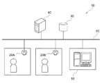
図1は、本実施形態における映像処理システムの動作環境の一例を示したネットワーク接続構成図である。本実施形態では、映像処理システムをネットワークカメラシステムに適用する。
ネットワークカメラシステム10は、複数台のネットワークカメラ(以下、単に「カメラ」ともいう)20A及び20Bと、ストレージ装置30と、管理サーバ装置40と、及び映像表示装置50とを備える。カメラ20A及び20B、ストレージ装置30、管理サーバ装置40及び映像表示装置50は、ネットワーク回線であるLAN(Local Area Network)60によって接続されている。なお、ネットワーク回線はLANに限定されるものではなく、インターネットやWAN (Wide Area Network)などであってもよい。
(First embodiment)
FIG. 1 is a network connection configuration diagram showing an example of the operating environment of the video processing system in the present embodiment. In this embodiment, the video processing system is applied to a network camera system.
The
カメラ20A及び20Bは撮像装置であり、所定の監視対象範囲(監視対象空間)に分散して配置されている。カメラ20Aの撮像範囲とカメラ20Bの撮像範囲とは、少なくとも一部が異なるものとする。すなわち、カメラ20A及び20Bはそれぞれ異なる撮像範囲を有していてもよいし、両者の撮像範囲の一部が重複していてもよい。
カメラ20A及び20Bは、被写体を撮影すると同時に、撮影した映像と管理サーバ装置40が管理している人物照合データとを照合して特定人物(監視対象者)を検出し、当該監視対象者の追尾処理を行う機能を有する。カメラ20A及び20Bは、撮影した映像データや映像解析処理後の映像解析データを含む映像データファイルを、LAN60を介してストレージ装置30に送信する。
The
The cameras 20 </ b> A and 20 </ b> B detect a specific person (monitoring person) by comparing the captured video and the person verification data managed by the
ストレージ装置30は記録装置であり、カメラ20A及び20Bから送信される映像データファイルが書き込まれる書込領域を備える。
管理サーバ装置40は、ストレージ装置30に記録された映像データファイルを収集する。そして、管理サーバ装置40は、収集されたデータ(現在の映像データ及び映像解析データ、並びに過去の映像データ及び映像解析データ)を利用し、監視対象範囲全体に亘る映像情報の管理を行う。
The
The
さらに、管理サーバ装置40は、上記の人物照合データを管理する。ここで、人物照合データとは、監視対象者を識別するための人物IDと、顔、服装、歩容など、監視対象者を特定するための情報(画像や特徴量)とを対応付けたデータである。管理サーバ装置40は、カメラ20A,20Bからのデータ送信要求に応じて、LAN60を介して人物照合データをカメラ20A,20Bに送信する。
映像表示装置50は、例えばパーソナルコンピューター(PC)により構成されており、カメラ20A及び20Bからの映像の表示制御を行う。映像表示装置50は、各カメラで撮像された複数の映像を一画面で分割表示する複数画面表示(マルチ画面表示)機能を有する。また、映像表示装置50は、監視対象者の追尾映像を表示する機能、及び次に監視対象者を撮像すると予測されるカメラの映像(出現予測映像)を、当該カメラで監視対象者を撮像する前に強調表示(明示的に表示)する機能を有する。
Furthermore, the
The
さらに、映像表示装置50は、イベントシーンなどの映像検索の操作を行うための入力手段の機能も有する。
なお、映像表示装置50のLAN60への物理的な接続形態は、有線に限定されるものではなく、例えばタブレット端末のように無線であってもよい。すなわち、プロトコル的に接続されていれば、物理的な形態にこだわるものではない。
また、図1に示すシステムにおいて、撮像装置であるカメラは2台以上で構成されていればよく、2台以上であれば何台でもよい。さらに、ストレージ装置30、管理サーバ装置40及び映像表示装置50がLAN60に接続される数は、図1に示す数に限定されるものではなく、アドレスなどで識別できれば多数存在してもよい。
また、監視対象である移動体は人物に限定されるものではなく、例えば車両等の任意の移動体オブジェクトであってもよい。
Further, the
Note that the physical connection form of the
In the system shown in FIG. 1, it is sufficient that the number of cameras that are imaging devices is two or more, and any number of cameras that are two or more is acceptable. Furthermore, the number of
In addition, the moving object to be monitored is not limited to a person, and may be an arbitrary moving object such as a vehicle.
次に、カメラ20A,20B及び映像表示装置50の具体的構成について説明する。
図2は、カメラ20A,20Bのハードウェア構成の一例を示す図である。なお、カメラ20Aとカメラ20Bとは同一のハードウェア構成を有するため、ここではカメラ20Aについてのみ説明する。
カメラ20Aは、CPU21と、ROM22と、RAM23と、外部メモリ24と、撮像部25と、入力部26と、通信I/F27と、システムバス28とを備える。
Next, specific configurations of the
FIG. 2 is a diagram illustrating an example of a hardware configuration of the
The
CPU21は、カメラ20Aにおける動作を統括的に制御するものであり、システムバス28を介して、各構成部(22〜27)を制御する。
ROM22は、CPU21が処理を実行するために必要な制御プログラム等を記憶する不揮発性メモリである。なお、当該プログラムは、外部メモリ24や着脱可能な記憶媒体(不図示)に記憶されていてもよい。
RAM23は、CPU21の主メモリ、ワークエリア等として機能する。すなわち、CPU21は、処理の実行に際してROM22から必要なプログラム等をRAM23にロードし、当該プログラム等を実行することで各種の機能動作を実現する。
The
The
The
外部メモリ24は、例えば、CPU21がプログラムを用いた処理を行う際に必要な各種データや各種情報等を記憶している。また、外部メモリ24には、例えば、CPU21がプログラム等を用いた処理を行うことにより得られた各種データや各種情報等が記憶される。
撮像部25は、被写体の撮像を行うためのものであり、CMOS(Complementary Metal Oxide Semiconductor)、CCD(Charge Coupled Device)等の撮像素子を含んで構成される。
The
The
入力部26は電源ボタンなどから構成され、カメラ20Aのユーザは、入力部26を介して当該カメラ20Aに指示を与えることができるようになっている。
通信I/F27は、外部装置(ここでは、ストレージ装置30及び管理サーバ装置40)と通信するためのインターフェースである。通信I/F27は、例えばLANインターフェースである。
システムバス28は、CPU21、ROM22、RAM23、外部メモリ24、撮像部25、入力部26及び通信I/F27を通信可能に接続する。
すなわち、CPU21は、ROM22に記憶されたプログラムを実行することで、上述した撮影処理及び追尾処理を実現する。
The
The communication I /
The system bus 28 connects the
That is, the
図3は、映像表示装置50のハードウェア構成の一例を示す図である。
映像表示装置50は、CPU51と、ROM52と、RAM53と、外部メモリ54と、入力部55と、表示部56と、通信I/F57と、システムバス58とを備える。
CPU51は、映像表示装置50における動作を統括的に制御するものであり、システムバス58を介して、各構成部(52〜57)を制御する。
ROM52は、CPU51が処理を実行するために必要な制御プログラム等を記憶する不揮発性メモリである。なお、当該プログラムは、外部メモリ54や着脱可能な記憶媒体(不図示)に記憶されていてもよい。
FIG. 3 is a diagram illustrating an example of a hardware configuration of the
The
The
The
RAM53は、CPU51の主メモリ、ワークエリア等として機能する。すなわち、CPU51は、処理の実行に際してROM52から必要なプログラム等をRAM53にロードし、当該プログラム等を実行することで各種の機能動作を実現する。
外部メモリ54は、例えば、CPU51がプログラムを用いた処理を行う際に必要な各種データや各種情報等を記憶している。また、外部メモリ54には、例えば、CPU51がプログラム等を用いた処理を行うことにより得られた各種データや各種情報等が記憶される。
The
The
入力部55は、キーボードやマウス等のポインティングデバイスで構成され、映像表示装置50のユーザは、入力部55を介して当該映像表示装置50に指示を与えることができるようになっている。
表示部56は、液晶ディスプレイ(LCD)等のモニタで構成される。
通信I/F57は、外部装置(ここでは、ストレージ装置30及び管理サーバ装置40)と通信するためのインターフェースである。通信I/F27は、例えばLANインターフェースである。
システムバス58は、CPU51、ROM52、RAM53、外部メモリ54、入力部55、表示部56及び通信I/F57を通信可能に接続する。
すなわち、CPU51は、ROM52に記憶されたプログラムを実行することで、上述した追尾映像及び出現予測映像の表示制御処理を実現する。
The
The
The communication I /
The
That is, the
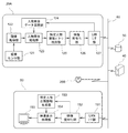
図4は、カメラ20A,20B及び映像表示装置50の機能ブロック図である。なお、カメラ20Aとカメラ20Bとは同一機能を有するため、図4ではカメラ20Aについてのみブロック図を図示している。
カメラ20Aは、撮像センサ部121と、現像処理部122と、人物照合処理部123と、人物照合データ蓄積部124と、特定人物移動パターン検出部125と、映像符号化部126と、LANI/F部127と、を備える。
FIG. 4 is a functional block diagram of the
The
撮像センサ部121は、撮像部25の撮像面に結像された光像を光電変換によりデジタル電気信号に変換し、これを現像処理部122に出力する。
現像処理部122は、撮像センサ部121により光電変換されて得られたデジタル電気信号に対して、所定の画素補間や色変換処理を行ない、RGBあるいはYUVなどのデジタル映像を生成する。また、現像処理部122は、現像を施した後のデジタル映像を用いて所定の演算処理を行ない、得られた演算結果に基づいてホワイトバランス、シャープネス、コントラスト、色変換などの映像処理を行う。
The
The
人物照合処理部123は、現像処理部122から出力される映像データから、特定人物(監視対象者)を検出する処理を行う。具体的には、人物照合処理部123は、上記映像データに対して、動体検知、人体検知、物体検知などの映像解析処理を行い、被写体を検出する。そして、検出した被写体と、後述する人物照合データ蓄積部124から取得した人物照合データとを照合する照合処理を行う。人物照合処理部123は、このとき照合された被写体を監視対象者として検出する。
The person
また、人物照合処理部123は、照合された人物のうち、フレーム間での位置関係から同定したものに固有のIDを付与し、当該人物の追尾処理も行う。人物照合処理部123は、これらの処理結果を、映像解析データとして特定人物移動パターン検出部125に出力する。
人物照合データ蓄積部124は、不揮発性のメモリなどに対する人物照合データの書き込み、読み出し及び消去が可能となっている。人物照合データ蓄積部124で書き込まれる人物照合データは、管理サーバ装置40で管理されている人物照合データである。つまり、人物照合データ蓄積部124は、管理サーバ装置40から送信される人物照合データを、後述するLANI/F部127によって取得し、上記メモリ等に書き込む。
In addition, the person
The person verification
特定人物移動パターン検出部125は、人物照合処理部123で照合され追尾された監視対象者の移動パターンを検出する。移動パターンとは、少なくとも監視対象者が進もうとしている方向を特定するための移動情報であり、ある一定期間のフレームでの監視対象者の移動方向、移動軌跡及び移動速度の組み合わせによって検出する。
例えば、予めカメラの撮影画角に応じて映像画面上のどの位置からどの位置への移動がどの方向の移動に対応付けられるかを設定しておくことが可能である。この場合、監視対象者が進んでいる方向を方位角、監視対象者の移動する軌跡を軌跡座標、監視対象者の移動する速度をフレーム間で移動した距離として、これらを組み合わせて移動パターンデータを生成する。なお、本実施形態において、監視対象者の移動方向は、第1の期間における監視対象者の移動方向によって特定される情報であり、監視対象者の移動軌跡は、第1の期間よりも長い第2の期間における監視対象者の移動方向によって特定される情報である。特定人物移動パターン検出部125は、検出した移動パターンデータを映像符号化部126へ出力する。
The specific person movement
For example, it is possible to set in advance which movement from which position on the video screen is associated with which movement in accordance with the shooting angle of view of the camera. In this case, the direction in which the monitoring subject is traveling is defined as the azimuth, the trajectory of the movement of the monitoring subject as the trajectory coordinates, and the moving speed of the monitoring subject as the distance moved between frames. Generate. In the present embodiment, the movement direction of the monitoring target person is information specified by the movement direction of the monitoring target person in the first period, and the movement trajectory of the monitoring target person is longer than the first period. This is information specified by the moving direction of the monitoring subject in the period 2. The specific person movement
なお、この特定人物移動パターン検出部125では、少なくとも監視対象者が進もうとしている方向がわかればよいため、監視対象者の移動方向及び移動軌跡の少なくとも一方により移動パターンを検出するようにしてもよい。
映像符号化部126は、現像処理部122、人物照合処理部123、特定人物移動パターン検出部125を通じて入力されるデジタル映像信号(映像データ、映像解析データ)に対して、配信用に圧縮、フレームレート設定などを施し、符号化する。ここでの配信用の圧縮方式は、所定の例えば、MPEG4(Moving Picture Experts Group phase4)、H.264、MJPEG(Motion-JPEG)またはJPEG(Joint Photographic Experts Group)などの規格に基づく。
The specific person movement
The
また、映像符号化部126は、特定人物移動パターン検出部125より入力された監視対象者の移動パターンデータをメタデータとして映像符号化データと重畳し、さらにmp4やmov形式などの映像データのファイル化をも行う。
LANI/F部127は、通信I/F27を制御して、管理サーバ装置40との通信制御を行う。このLANI/F部127は、管理サーバ装置40から送信される人物照合データを受信し、人物照合データ蓄積部124へ送信する。
In addition, the
The LAN I /
また、LANI/F部127は、ストレージ装置30のLANI/F部(不図示)と連携することにより、例えば、NFS(Network File System)やCIFS(Common Internet File System)などのファイルシステムを構築して、映像符号化部126で符号化した映像データファイルの記録を行う。
映像表示装置50は、LANI/F部151と、映像復号化部152と、特定人物出現情報生成部153と、映像表示処理部154と、ディスプレイ155と、を備える。
LANI/F部151は、カメラ20AのLANI/F部127と同等の機能を有する。このLANI/F部151は、管理サーバ装置40から送信される各種管理情報を受信したり、ストレージ装置30に記憶された各カメラからの映像データファイルを受信したりする。
The LAN I /
The
The LAN I /
映像復号化部152は、LANI/F部151で受信した映像データファイルを、伸張し復号化して、デジタル映像信号とメタデータとして重畳された監視対象者の移動パターンデータとに分離する。映像復号化部152は、復号されたデジタル映像信号を映像表示処理部154に、分離された監視対象者の移動パターンデータを特定人物出現情報生成部153に出力する。
特定人物出現情報生成部153は、映像復号化部152から入力した監視対象者の移動パターンデータをもとに、特定人物出現情報を生成する。特定人物出現情報には、監視対象者がどのカメラの撮像範囲に向かって進んでいるのかを示す情報(監視対象者を次に撮像するカメラの情報)と、監視対象者を次に撮像するカメラの映像画面上において、当該監視対象者がどのあたりに出現されるかの範囲を示す情報とを含む。
The
The specific person appearance
具体的には、特定人物出現情報生成部153は、予め記憶された監視対象範囲のマップ情報(以下、カメラマップともいう)と、予め記憶された各カメラの設置位置(設置座標)及び各カメラの撮影方向・撮影範囲・画角等のカメラ情報とを参照し、監視対象者の移動パターンデータをもとに特定人物出現情報を生成する。すなわち、特定人物出現情報生成部153は、上記カメラマップと上記カメラ情報とに基づいて、各カメラで撮影されている映像画面に対して隣接して設置されているカメラの方向を設定しておく。そして、その設定情報と監視対象者の移動パターンデータとに基づいて、監視対象者がどのカメラの方向に進んでいるのかと、監視対象者が次に撮像される映像画面上のどのあたりに出現されるかの範囲とを求める。
Specifically, the specific person appearance
映像表示処理部154は、映像復号化部152から入力したデジタル映像信号と、特定人物出現情報生成部153から入力した特定人物出現情報とを用いて、表示部56を構成するディスプレイ155の画面表示を制御する。この映像表示処理部154は、上述したマルチ画面表示、追尾映像の表示、出現予測映像の強調表示などを行う。
このように、本実施形態では、1つのカメラの映像から監視対象者の移動パターンを検出し、当該移動パターンに応じて、次に監視対象者が映るはずのカメラを予測する。そして、本実施形態の映像表示装置50は、当該予測された結果を特定するための表示を、次に監視対象者が移るはずのカメラが監視対象者を撮像する前におこなわせる。予測された結果を特定するための表示とは、例えば、予測されたカメラにより撮像された映像(出現予測映像)の強調表示である。強調表示の方法は、例えば、出現予測映像を拡大表示したり、出現予測映像の枠をフラッシュないし点滅(ブリンク)させたり、ハイライト表示したり、矢印などによって明示させたりといった方法がある。ただし、強調表示の方法は、上記の方法に限らない。また、予測された結果を特定するための表示は、強調表示に限らない。例えば、予測されたカメラの撮像画像がディスプレイ上に表示されていない場合に、当該カメラの撮像画像を、予測結果に応じてディスプレイ上に表示させることも、予測された結果を特定するための表示に含まれる。
The video
As described above, in the present embodiment, the movement pattern of the monitoring target person is detected from the video of one camera, and the camera that the monitoring target person is supposed to appear next is predicted according to the movement pattern. Then, the
さらに、映像表示処理部154は、出現予測映像の表示に際し、当該出現予測映像に監視対象者が出現予測される範囲(出現予測範囲)を重畳表示する。ここで、出現予測範囲の形状は任意であって、例えば矩形状であっても円形状であってもよい。また、出現予測範囲の表示方法は、当該出現予測範囲が視認可能な方法であればいずれの方法でも採用可能である。例えば、出現予測範囲の枠を表示したり、出現予測範囲の色調を変更したりしてもよい。
Furthermore, when displaying the appearance prediction video, the video
なお、ここでは、次に監視対象者を撮像するはずのカメラからの映像を強調表示することで、監視対象者の出現予測結果に応じて、特定の撮像画像を強調表示する場合について説明したが、映像表示以外の方法を用いてもよい。例えば、音声により次にどのカメラで監視対象者を撮像するのかを知らせたり、次に監視対象者を撮像すると予測されるカメラを特定するためのランプを点灯させたりしてもよい。 Note that, here, a case has been described in which a specific captured image is highlighted according to the appearance prediction result of the monitoring target person by highlighting the video from the camera that is to capture the next monitoring target person. A method other than video display may be used. For example, it may be notified by voice which camera is to be used to capture the monitoring subject next, or a lamp for identifying a camera that is predicted to capture the monitoring subject next may be lit.
図5は、カメラ20Aで実行する撮像処理手順を示すフローチャートである。図5に示される処理は、図2で示すCPU21が、図5のフローチャートに対応する処理の実行のために必要なプログラムを実行することにより、実現される。また本実施形態において、図5の処理は、ユーザからカメラ20Aに対する撮影開始指示が入力されたタイミングで開始される。ただし、図5の処理の開始のタイミングは上記のタイミングに限らない。なお、カメラ20Bにおいても、図5に示す撮像処理と同一の処理を実行するものとする。
FIG. 5 is a flowchart showing an imaging processing procedure executed by the
先ず、ステップS1で、カメラ20Aは、管理サーバ装置40が管理している人物照会データを取得する。すなわち、カメラ20Aは、管理サーバ装置40に対して人物照会データ送信要求を送信し、それを受けて管理サーバ装置40が送信した人物照会データを受信する。
次にステップS2では、カメラ20Aは、ステップS1で取得した人物照会データを所定の記憶領域(メモリ等)に蓄積し、ステップS3に移行する。
ステップS3では、カメラ20Aは、撮像部25による撮像を開始し、ステップS4に移行する。このステップS3では、カメラ20Aは、撮像センサ部121から得られたデジタル電気信号に対して所定の現像処理を施し、映像データを生成する処理を開始する。
First, in step S1, the
Next, in step S2, the
In step S3, the
ステップS4では、カメラ20Aは、撮像部により撮像され、現像処理が施された映像から人物映像を検出し、ステップS5に移行する。
ステップS5では、カメラ20Aは、ステップS4で検出した人物映像を人物照会データ蓄積部125に蓄積された人物照会データと照合する。照合の結果、撮像された人物映像と人物照会データの人物とが一致しない場合には、監視対象者は撮影されていないと判断してステップS4に移行する。すなわち、照合に用いた映像データと照合処理後の監視対象者が非検出であることを示す映像解析データとを符号化し、符号化した映像データファイルをストレージ装置30に対して送信する。
ステップS5の照合の結果、撮像された人物映像と人物照会データの人物とが一致した場合には、監視対象者が撮影されていると判断してステップS6に移行する。
ステップS6では、カメラ20Aは、監視対象者の追尾処理を行う。すなわち、監視対象者に識別子となるIDを付与して当該監視対象者の追尾を行う。
In step S4, the
In step S5, the
If the captured person image matches the person in the person inquiry data as a result of the collation in step S5, it is determined that the monitoring subject has been photographed, and the process proceeds to step S6.
In step S6, the
次にステップS7では、カメラ20Aは、監視対象者を追尾可能となってから予め設定した一定時間が経過したか否かを判定する。ここで、上記一定時間は、監視対象者の移動パターンが検出可能な程度の時間に設定する。そして、一定時間が経過していない場合には、ステップS6に移行し、当該一定時間が経過するまで監視対象者の追尾を継続する。その間、映像データと追尾処理後の映像解析データとを符号化し、符号化した映像データファイルをストレージ装置30に対して送信する。
そして、ステップS7で一定時間が経過したと判断すると、カメラ20Aは、ステップS8に移行して、監視対象者の移動パターンを検出し、移動パターンデータを生成する。
Next, in step S7, the
If it is determined in step S7 that the fixed time has elapsed, the
次にステップS9で、カメラ20Aは、ステップS8で生成した移動パターンデータをストレージ装置30に対して送信する。すなわち、このステップS9では、カメラ20Aは、映像データと追尾処理後の映像解析データとを符号化した映像符号化データに対して、移動パターンデータをメタデータとして重畳した映像データファイルをストレージ装置30に送信する。
ステップS10では、カメラ20Aは、監視対象者の追尾を終了するか否かを判定する。ここでは、映像から監視対象者が消失したと判断したとき、監視対象者の追尾を終了すると判断する。監視対象者が映像から消失しておらず、監視対象者の追尾を継続する場合にはステップS6に移行し、監視対象者の追尾を終了する場合にはステップS11に移行する。
Next, in step S <b> 9, the camera 20 </ b> A transmits the movement pattern data generated in step S <b> 8 to the
In step S <b> 10, the camera 20 </ b> A determines whether or not tracking of the monitoring subject is to be ended. Here, when it is determined that the monitoring subject disappears from the video, it is determined that the tracking of the monitoring subject is finished. If the monitoring subject has not disappeared from the video and the tracking of the monitoring subject continues, the process proceeds to step S6, and if the tracking of the monitoring subject is terminated, the process proceeds to step S11.
ステップS11では、カメラ20Aは、撮像部による撮像を終了するか否かを判定する。例えば、管理サーバ装置40から撮影映像送信停止の要求を受信した場合などには、撮像終了と判断して撮像処理を終了する。一方、このステップS11で、撮像継続と判断した場合にはステップS4に移行する。
図6は、映像表示装置50で実行する映像表示処理手順を示すフローチャートである。図6に示される処理は、図3で示すCPU51が、図6のフローチャートに対応する処理の実行のために必要なプログラムを読み出して実行することにより、実現される。本実施形態において、図6の処理は、ユーザからカメラ20Aに対する撮影開始指示が行われてから所定時間ごとに繰り返し実行される。ただし、図6の処理の実行タイミングは上記のタイミングに限らない。
In step S <b> 11, the camera 20 </ b> A determines whether or not to finish imaging by the imaging unit. For example, when a request for stopping the transmission of captured video is received from the
FIG. 6 is a flowchart showing a video display processing procedure executed by the
先ずステップS21で、映像表示装置50は、監視対象範囲内に設置されているすべてのカメラからの映像データファイルをストレージ装置30から取得し、ステップS22に移行する。
ステップS22では、映像表示装置50は、ステップS21で取得した各映像データファイルを復号化し、当該映像データファイルに含まれる各カメラの映像データをもとに、各カメラ映像をマルチ画面表示する。
First, in step S21, the
In step S22, the
次にステップS23では、映像表示装置50は、各映像データファイルに含まれる映像解析データをもとに、各カメラからの映像のうち、監視対象者が撮像されている映像(追尾映像)を選択し、ステップS24に移行する。
ステップS24では、映像表示装置50は、ステップS23で選択した追尾映像を強調表示する。例えば、映像表示装置50は、監視対象者が撮像された映像データと当該映像データの映像解析データとを重畳し、ディスプレイ上で拡大表示する。
Next, in step S23, the
In step S24, the
次にステップS25で、映像表示装置50は、各映像データファイルに含まれる移動パターンデータを解析し、各カメラからの映像のうち、監視対象者を次に撮像するカメラの映像(出現予測映像)を選択する。
次にステップS26で、映像表示装置50は、各映像データファイルに含まれる移動パターンデータを解析し、ステップS25で選択した出現予測映像の表示画面上において、監視対象者が出現すると予測される範囲(出現予測範囲)を特定し、ステップS27に移行する。
ステップS27では、映像表示装置50は、ステップS25で選択した出現予測映像をディスプレイ上で強調表示(例えば、拡大表示)し、映像表示処理を終了する。このとき、映像表示装置50は、出現予測映像の表示に際し、ステップS26で特定した出現予測範囲を当該出現予測映像に重畳して表示する。
Next, in step S25, the
Next, in step S26, the
In step S27, the
なお、図5において、ステップS1の処理がLANI/F部127の処理に対応し、ステップS2が人物照合データ蓄積部124の処理に対応し、ステップS3が撮像センサ部121及び現像処理部122の処理に対応している。また、ステップS4〜S6の処理が人物照合処理部123の処理に対応し、ステップS7及びS8の処理が特定人物移動パターン検出部125の処理に対応している。さらに、ステップS9の処理が映像符号化部126の処理に対応している。
In FIG. 5, the process of step S <b> 1 corresponds to the process of the LAN I /
また、図6において、ステップS21の処理がLANI/F部151及び映像復号化部152の処理に対応し、ステップS22〜S24の処理が映像表示処理部154の処理に対応している。さらに、ステップS25及びS26の処理が特定人物出現情報生成部153の処理に対応し、ステップS27の処理が映像表示処理部154の処理に対応している。
In FIG. 6, the process of step S21 corresponds to the process of the LAN I /
さらに、上記において、人物照合処理部123が特定移動体検出手段に対応し、特定人物移動パターン検出部125が移動情報検出手段に対応している。また、特定人物出現情報生成部153が予測手段に対応し、映像表示処理部154が表示制御手段に対応している。さらにまた、図6のステップS22が複数画面表示部に対応し、ステップS26が出現予測範囲特定手段に対応している。
Furthermore, in the above, the person
(第一の実施形態の動作)
次に、第一の実施形態の動作について説明する。
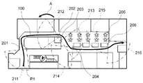
ここでは、図7に示すように、監視対象範囲に6台のカメラ201〜206が分散して配置されている環境での動作について説明する。ここで、カメラ201〜206は、上述したカメラ20A及び20Bと同一構成を有する。図7において、カメラ201は撮影範囲211内の被写体を撮像し、カメラ202は撮像範囲212内の被写体を撮像する。カメラ203〜206についても同様である。
(Operation of the first embodiment)
Next, the operation of the first embodiment will be described.
Here, as shown in FIG. 7, an operation in an environment in which six
先ず、ネットワークカメラシステム10が運用開始となると、カメラ201〜206は、それぞれ図5に示す撮像処理を開始する。そして、カメラ201〜206は、それぞれ管理サーバ装置40から監視対象者である人物P1の照合データを含む人物照合データを取得し(ステップS1)、これをメモリ等に記憶する(ステップS2)。その後、カメラ201〜206は、各々の撮像範囲211〜216の撮像を開始し(ステップS3)、撮像した映像データを解析して監視対象者が撮像されているか否かを判断する(ステップS4,S5)。
First, when the
図7に示す監視対象範囲内を、監視対象者である人物P1が矢印100に示す移動軌跡で通過する場合、先ずカメラ201で監視対象者P1を撮像する。すなわち、カメラ201は、人物照合処理の結果、自身が撮影した人物が人物照合データと一致する監視対象者P1であると判断し(ステップS5でYes)、当該監視対象者P1の追尾を行う(ステップS6)。また、カメラ201は、映像データと共に追尾処理後の映像解析データをストレージ装置30へ送信する(ステップS7でNo)。
When the person P1 who is the person to be monitored passes along the movement locus indicated by the
このとき、映像表示装置50は、ストレージ装置30に記憶された映像データファイルを取得し(ステップS21)、カメラ201〜206が撮影した映像をマルチ画面表示する共に(ステップS22)、カメラ201からの監視対象者P1の追尾映像を画面上に大きく表示する(ステップS24)。このときの映像表示装置50のディスプレイ155における出力画面の例を図8に示す。
図8において、出力画面500中の領域501,501,…,506は、それぞれカメラ201(camera1),202(camera2),…,206(camera6)が撮影した映像を表示する領域である。また、領域511は、監視対象者の追尾映像を表示する領域である。この時点では、領域511には、カメラ201の映像が表示される。
At this time, the
8,
さらに、領域512は、監視対象者の出現予測映像を表示する領域である。カメラ201で監視対象者P1を追尾可能な状態となった時点から一定時間が経過するまでの間は、カメラ201で監視対象者P1の移動パターンが検出できない(ステップS7でNo)。そのため、この期間は出力画面500の領域512には何も表示されない。
その後、カメラ201で監視対象者P1を追尾可能な状態となった時点から一定時間が経過すると、カメラ201は監視対象者P1の移動パターンを検出する(ステップS8)。そして、カメラ201は、検出した移動パターンを示す移動パターンデータを映像データと共にストレージ装置30へ送信する(ステップS9)。
Further, the
Thereafter, when a certain period of time has elapsed since the
このとき、映像表示装置50は、ストレージ装置30に記憶された映像データファイルを取得することで、カメラ201が送信した移動パターンデータを取得する。そして、取得したカメラ201からの移動パターンデータをもとに、監視対象者P1の移動方向に設置されているカメラの映像を選択する。監視対象者P1は、図7に示すようにカメラ202の方向に進んでいるため、この場合にはカメラ202の映像が出現予測映像として選択される(ステップS25)。
At this time, the
また、映像表示装置50は、監視対象者P1がカメラ202で撮影されたとき、当該監視対象者P1がカメラ202の撮影画面上のどの範囲に出現するかを予測する(ステップS26)。
図7に示すように、監視対象者P1がカメラ201の撮影範囲211からカメラ202の撮影範囲212の方向へ移動した場合、カメラ201の撮影画面上では、監視対象者P1は図9の矢印の方向へ移動する。そして、監視対象者P1がカメラ202の撮影範囲212内に入り、カメラ202で監視対象者P1を撮像すると、カメラ202の撮影画面上では、監視対象者P1は図10の破線で示す位置に出現する。
Further, when the monitoring subject P1 is photographed by the
As shown in FIG. 7, when the monitoring subject P1 moves in the direction from the
映像表示装置50は、カメラ201が送信した監視対象者P1の移動パターンデータをもとに、カメラ202が監視対象者P1を撮像した際にカメラ202の撮影画面上で図10の破線で示す位置に出現することを予測する。そして、映像表示装置50は、監視対象者P1の出現予測映像、即ちカメラ202で撮像した映像を、監視対象者P1の出現予測範囲と共に表示する(ステップS27)。このときの映像表示装置50のディスプレイ155における出力画面の例を図11に示す。
このように、映像表示装置50は、出力画面500の領域512に、カメラ202が撮像した映像を表示する。すなわち、映像表示装置50は、監視対象者P1の出現予測映像を拡大表示することで、当該出現予測映像を強調表示する。また、映像表示装置50は、監視対象者P1の出現予測範囲521も強調表示する。
Based on the movement pattern data of the monitoring subject P1 transmitted by the
Thus, the
なお、図11に示すように予めすべてのカメラ201〜206からの映像が表示されている場合には、出現予測映像を表示している部分の枠をフラッシュさせる、あるいは矢印などによって明示させるなどの方法を用いて出現予測映像を強調表示してもよい。これにより、監視員は、どのカメラからの映像が出現予測映像として拡大表示されているかを容易に認識することができる。また、上記のようにマルチ画面表示中で出現予測映像を強調表示する方法を採用した場合には、出現予測映像の拡大表示を行わなくてもよい。
In addition, as shown in FIG. 11, when the images from all the
その後、監視対象者P1がカメラ201の撮影範囲211を通過し、カメラ202の撮影範囲212に入ると、カメラ202で監視対象者P1を撮像する。そのため、この場合には、カメラ202で監視対象者P1の追尾及び監視対象者P1の移動パターンの検出を行う。また、カメラ202の次に監視対象者P1を撮像するカメラはカメラ203となる。
Thereafter, when the monitoring subject P1 passes through the
この場合、映像表示装置50は、カメラ202の映像を監視対象者P1の追尾映像として選択し、カメラ202が送信した監視対象者P1の移動パターンデータをもとに、カメラ203で撮像した映像を出現予測映像として選択する。そのため、映像表示装置50は、図11に示す領域511の追尾映像の表示をカメラ202で撮像した映像の表示に切り替えると共に、領域512の出現予測映像の表示をカメラ203で撮像した映像の表示に切り替える。
以降、監視対象者P1がカメラ206の撮影範囲216を通過するまで同様の動作を繰り返す。
In this case, the
Thereafter, the same operation is repeated until the monitoring subject P1 passes through the
なお、監視対象者の移動パターンによっては、確率的に複数のカメラの映像が出現予測映像として選択される場合がある。この場合は、候補となる複数の出現予測映像を選択して拡大表示するようにしてもよい。
また、上記の例では、監視対象者が1人である場合について説明したが、監視対象者が複数人の場合にも適用可能である。この場合、監視対象者毎に、それぞれ追尾映像と出現予測映像とを表示すればよい。
Depending on the movement pattern of the person to be monitored, videos from a plurality of cameras may be selected as appearance prediction videos. In this case, a plurality of candidate appearance prediction videos may be selected and displayed in an enlarged manner.
In the above example, the case where there is one person to be monitored has been described. However, the present invention can also be applied to cases where there are a plurality of persons to be monitored. In this case, a tracking image and an appearance prediction image may be displayed for each person to be monitored.
(第一の実施形態の効果)
以上のように、本実施形態では、監視対象空間に複数のカメラが設置されている環境で、監視対象者を撮像している1つのカメラ(第一のカメラ)の映像データをもとに、第一のカメラの次に当該監視対象者を撮像する第二のカメラを予測し、その予測された第二のカメラによる撮像画像を強調表示する。第二のカメラの予測に際し、先ず、複数のカメラで撮像された各画像から、監視対象者を検出する。次に、当該監視対象者が移動しようとしている方向を特定するための移動情報を検出する。そして、検出した移動情報と、複数のカメラの撮像範囲を示す情報とに基づいて、上記第二のカメラを予測し、予測されたカメラの撮像画像を強調表示する。
(Effect of the first embodiment)
As described above, in the present embodiment, in an environment in which a plurality of cameras are installed in a monitoring target space, based on video data of one camera (first camera) that captures a monitoring target person, Next to the first camera, a second camera that captures the person to be monitored is predicted, and an image captured by the predicted second camera is highlighted. When predicting the second camera, first, a monitoring target person is detected from each image captured by a plurality of cameras. Next, movement information for specifying the direction in which the monitoring subject is about to move is detected. Then, based on the detected movement information and information indicating the imaging ranges of a plurality of cameras, the second camera is predicted, and the captured images of the predicted cameras are highlighted.
そのため、複数のカメラの映像を警備室などのモニタで監視員が監視する際、当該監視員は、次に監視対象者が映るはずのカメラを容易に認識することができ、監視対象者を容易に映像で追尾することができる。
また、監視対象者の出現予測をするので、単に監視対象者の現在位置近傍に配置されているカメラ(監視対象者を撮像しているカメラに隣接配置するカメラ)の映像を表示する場合と比較して、容易且つ適切に監視対象者を映像で追尾することができる。
このとき、監視対象者の移動方向、移動軌跡、移動速度を示す情報の組み合わせから当該監視対象者が移動しようとしている方向を特定するため、次に監視対象者を撮像するカメラを精度よく予測することができる。
For this reason, when the monitor monitors the images of multiple cameras using a monitor such as a security room, the monitor can easily recognize the next camera that the monitoring target should appear, and the monitoring target can be easily identified. Can be tracked with video.
In addition, since the appearance of the monitoring subject is predicted, it is compared with the case where the image of the camera (camera arranged adjacent to the camera capturing the monitoring subject) is simply displayed near the current position of the monitoring subject. Thus, the person to be monitored can be tracked easily and appropriately with the video.
At this time, in order to identify the direction in which the monitoring target person is about to move from the combination of information indicating the movement direction, movement trajectory, and movement speed of the monitoring target person, the next camera for imaging the monitoring target person is accurately predicted. be able to.
また、上記予測した結果を表示する方法としては、第二のカメラの映像を強調表示する方法を採用することができる。これにより、監視員は、次に監視対象者が映るはずのカメラの映像を当該監視対象者が映る前に確認することができる。このとき、第二のカメラの映像をマルチ画面表示している画像よりも大きく表示(拡大表示)すれば、監視対象者の出現予測映像を容易に確認することができる。
また、マルチ画面表示において、第二のカメラの映像を他の映像とは異なる視覚的効果(画面枠フラッシュ、矢印表示など)を付与して表示すれば、監視員は、どのカメラからの映像が出現予測映像として選択されているかを容易に認識することができる。
Moreover, as a method for displaying the predicted result, a method for highlighting the video of the second camera can be employed. Thereby, the monitoring person can confirm the image | video of the camera which the monitoring subject should appear next before the said monitoring subject shows. At this time, if the video of the second camera is displayed larger (enlarged display) than the image displayed on the multi-screen, the appearance prediction video of the monitoring subject can be easily confirmed.
Also, in multi-screen display, if the video from the second camera is displayed with a visual effect (screen frame flash, arrow display, etc.) different from the other video, the observer can view the video from which camera. It can be easily recognized whether it is selected as an appearance prediction image.
さらに、監視対象者が移動しようとしている方向を示す情報と、第二のカメラの撮像範囲を示す情報とに基づいて、第二のカメラで監視対象者を撮像したときの、第二のカメラの撮影画像内における監視対象者の出現予測範囲を特定することもできる。この場合、出現予測映像の表示に際し、当該出現予測映像における監視対象者の出現予測範囲を示す情報を重畳して表示してもよい。これにより、監視員は、監視対象者が出現予測映像内のどのあたりに出現するかを事前に把握することができ、出現予測映像内に監視対象者が出現したときに当該監視対象者を容易に認識することができる。 Furthermore, based on the information indicating the direction in which the monitoring target person is about to move and the information indicating the imaging range of the second camera, the second camera is configured to capture the monitoring target person. It is also possible to specify the predicted range of appearance of the monitoring subject in the captured image. In this case, when the appearance prediction video is displayed, information indicating the appearance prediction range of the monitoring target person in the appearance prediction video may be superimposed and displayed. As a result, the monitoring staff can grasp in advance where the monitoring target person appears in the appearance prediction video, and can easily identify the monitoring target person when the monitoring target appears in the appearance prediction video. Can be recognized.
(第二の実施形態)
次に、本発明における第二の実施形態について説明する。
この第二の実施形態は、パン・チルト・ズーム制御機能が搭載されたカメラを用いたものである。
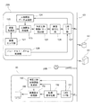
すなわち、図1におけるカメラ20A及び20Bは、図12に示すように、パン・チルト・ズーム制御部128を備える。なお、この図12においては、図4と同一構成を有する部分には同一符号を付し、以下、図4と構成の異なる部分を中心に説明する。
パン・チルト・ズーム制御部128は、カメラ20Aのパン機構、チルト機構及びズーム機構をそれぞれ制御するための制御指令を各機構の駆動部に対して出力し、カメラ20Aの撮影方向・範囲・画角を制御する。
(Second embodiment)
Next, a second embodiment of the present invention will be described.
The second embodiment uses a camera equipped with a pan / tilt / zoom control function.
That is, the
The pan / tilt /
また、パン・チルト・ズーム制御部128は、変更した撮影方位角データをLANI/F部127を介して管理サーバ装置40へ送信する。
映像表示装置50は、LANI/F部151を介して各カメラから送信された撮影方位角データを管理サーバ装置40から取得する。取得した撮影方位角データは、特定人物出現情報生成部153に送られ、特定人物出現情報の生成に用いられる。
特定人物出現情報は、上述したように、予め記憶されたカメラマップと、各カメラの設置位置(設置座標)及びカメラ情報とを参照し、監視対象者の移動パターンデータをもとに生成する。そこで、特定人物出現情報生成部153は、取得した撮影方位角データに基づいて記憶されている各カメラの撮影方向・範囲・画角を更新し、特定人物出現情報を生成する。
なお、上記において、パン・チルト・ズーム制御部128が駆動制御手段に対応している。
Further, the pan / tilt /
The
As described above, the specific person appearance information is generated based on the movement pattern data of the monitoring target person with reference to the camera map stored in advance, the installation position (installation coordinates) and camera information of each camera. Accordingly, the specific person appearance
In the above description, the pan / tilt /
(第二の実施形態の動作)
次に、第二の実施形態の動作について説明する。
ここでは、図13に示す監視対象範囲内を、監視対象者P1が矢印100に示す移動軌跡で通過する場合について説明する。なお、図13において、カメラ201〜206は、上述したカメラ20A及び20Bと同一構成を有する。また、図13において、カメラ201は撮影範囲211内の被写体を撮像し、カメラ202は撮像範囲212内の被写体を撮像する。カメラ203〜206についても同様である。
(Operation of Second Embodiment)
Next, the operation of the second embodiment will be described.
Here, a case where the monitoring subject P1 passes through the monitoring target range shown in FIG. In FIG. 13, the
カメラ201〜206は、それぞれパン・チルト・ズーム制御機能を有し、監視対象者P1がカメラ201の撮影範囲211からカメラ202の撮影範囲212の方向へ移動したときに、カメラ202の撮影範囲が図13の矢印Aに示すように変化したものとする。
この場合、映像表示装置50は、カメラ202から送信された撮影方位角データを取得し、取得した撮影方位角データをもとに当該カメラ202の変更後の撮影範囲212を求める。そして、映像表示装置50は、変更後の撮影範囲212を示す情報をもとに監視対象者P1の出現予測範囲を特定し、これを出現予測映像に重畳して表示する。このときの出力画面を図14に示す。
Each of the
In this case, the
カメラ202の初期状態の撮影範囲をもとに出現予測範囲を特定した場合、図11に示すように出現予測範囲521は出現予測映像中の左側になるのに対し、新たに取得した撮影範囲をもとに出現予測範囲を特定すると、図14に示すように、出現予測範囲521は出現予測映像中の上側に更新される。このように、正確な出現予測範囲を表示することができる。
When the appearance prediction range is specified based on the initial shooting range of the
(第二の実施形態の効果)
以上のように、各カメラがパン機構、チルト機構及びズーム機構の少なくとも1つを備える場合、これら各機能を駆動制御するための制御指令に基づいて、監視対象者を撮像している第一のカメラの次に当該監視対象者を撮像する第二のカメラの撮像範囲を把握することができる。したがって、その情報に基づいて出現予測映像内における監視対象者の出現予測範囲を特定することで、上記機構により各カメラの撮像範囲が変化し得る環境においても監視対象者の出現予測を適切に行うことができる。
(Effect of the second embodiment)
As described above, when each camera includes at least one of a pan mechanism, a tilt mechanism, and a zoom mechanism, the first person who is imaging the person to be monitored based on the control command for driving and controlling these functions. It is possible to grasp the imaging range of the second camera that captures the person to be monitored next to the camera. Therefore, by specifying the appearance prediction range of the monitoring target person in the appearance prediction video based on the information, the appearance prediction of the monitoring target person is appropriately performed even in an environment where the imaging range of each camera can be changed by the above mechanism. be able to.
(応用例)
上記各実施形態においては、映像表示装置50で出現予測映像を表示した後、表示した出現予測が正しいか否かの正否判定をユーザから入力可能な構成としてもよい。この場合、映像表示装置50に、ユーザが入力した正否判定を示す情報(正否情報)を取得する正否情報取得部を設け、取得した正否情報に基づいて、監視対象者の移動パターンの検出に用いる移動方向、移動軌跡、移動速度の重み付けを変化させるなどの学習機能を付与してもよい。これにより、より適切な出現予測が可能となる。
(Application examples)
In each of the above embodiments, after the appearance prediction video is displayed on the
また、上記各実施形態においては、映像表示装置50に、監視対象(例えば、人物の特徴量)によって、出現予測を行うか否かを判定する実施判定部を備えてもよい。この場合、例えば、第一の特徴量を有する人物は、図7におけるカメラ201〜204の撮影範囲で出現予測を行い、第二の特徴量を有する人物は、すべてのカメラ201〜206の撮影範囲で出現予測を行い、第三の特徴量を有する人物は、出現予測を行わないなど、出現予測を行う範囲を設定してもよい。この実施判定を行うための設定情報は、管理サーバ装置40が管理している人物照合データに含めておけばよい。
In each of the above embodiments, the
(変形例)
上記各実施形態においては、人物照合処理と移動パターン検出処理とをカメラ(撮像装置)側で行う場合について説明したが、管理サーバ装置40で実行したり、映像表示装置50で実行したりしてもよい。また、監視対象者を検出するための人物照合処理は、例えばユーザが行うようにしてもよい。すなわち、各カメラで撮像した映像を映像表示装置50で表示し、これらの映像を確認したユーザが、表示画面上で(画面タッチやマウス操作等により)監視対象者を選択してもよい。
(Modification)
In each of the above-described embodiments, the case where the person verification process and the movement pattern detection process are performed on the camera (imaging apparatus) side has been described. However, the person verification process and the movement pattern detection process are performed by the
さらに、上記各実施形態においては、管理サーバ装置40で実行する処理(人物照合データの管理や監視対象範囲全体に亘る管理など)を、映像表示装置50で実行するようにしてもよい。また、各カメラからの映像データファイルをストレージ装置30に記憶する場合について説明したが、当該映像データファイルは各カメラで保持してもよいし、映像表示装置50が保持してもよい。
Furthermore, in each of the above-described embodiments, processing (such as management of person verification data and management over the entire monitoring target range) executed by the
(その他の実施形態)
本発明は、上述の実施形態の1以上の機能を実現するプログラムを、ネットワーク又は記憶媒体を介してシステム又は装置に供給し、そのシステム又は装置のコンピュータにおける1つ以上のプロセッサーがプログラムを読出し実行する処理でも実現可能である。また、1以上の機能を実現する回路(例えば、ASIC)によっても実現可能である。
(Other embodiments)
The present invention supplies a program that realizes one or more functions of the above-described embodiments to a system or apparatus via a network or a storage medium, and one or more processors in a computer of the system or apparatus read and execute the program This process can be realized. It can also be realized by a circuit (for example, ASIC) that realizes one or more functions.
10…映像処理システム、20A,20B…ネットワークカメラ(カメラ)、30…ストレージ装置、40…管理サーバ装置、50…映像表示装置、P1…監視対象者
DESCRIPTION OF
Claims (12)
前記特定移動体検出手段で検出した特定移動体が移動しようとしている方向を少なくとも特定するための移動情報を検出する移動情報検出手段と、
前記移動情報検出手段で検出した移動情報と、前記複数の撮像部のそれぞれの撮像範囲を示す情報とに基づいて、当該特定移動体を撮像している第一の撮像部の次に当該特定移動体を撮像する第二の撮像部を予測する予測手段と、
前記予測手段で予測した結果を特定するための表示を、前記第二の撮像部で前記特定移動体を撮像する前に行わせる表示制御手段と、を備え、
前記表示制御手段は、前記複数の撮像部で撮像された複数の画像を1つの画面で分割表示可能な複数画面表示部に、前記複数の画像を表示させ、前記第二の撮像部で撮像された画像を、前記複数画面表示部で分割表示される前記複数の画像よりも大きく表示させるための表示制御を、前記第二の撮像部で前記特定移動体を撮像する前に実行することを特徴とする映像処理装置。 Specific moving body detection means for detecting a specific moving body that is a monitoring target from each image that is installed in a monitoring target space and captured by a plurality of imaging sections each having a shooting range that is at least partially different from other imaging sections. When,
Movement information detecting means for detecting movement information for specifying at least the direction in which the specific moving body detected by the specific moving body detecting means is moving;
Based on the movement information detected by the movement information detection means and the information indicating the imaging ranges of the plurality of imaging units, the specific movement is next to the first imaging unit imaging the specific moving body. Predicting means for predicting a second imaging unit that images the body;
Display control means for performing display for specifying the result predicted by the prediction means before imaging the specific moving body by the second imaging unit,
The display control unit displays the plurality of images on a multi-screen display unit that can divide and display a plurality of images captured by the plurality of imaging units on a single screen, and is captured by the second imaging unit. Display control for displaying a larger image than the plurality of images divided and displayed on the multi-screen display unit before the specific moving body is imaged on the second imaging unit. A video processing device.
前記特定移動体検出手段で検出した特定移動体が移動しようとしている方向を少なくとも特定するための移動情報を検出する移動情報検出手段と、 Movement information detecting means for detecting movement information for specifying at least the direction in which the specific moving body detected by the specific moving body detecting means is moving;
前記移動情報検出手段で検出した移動情報と、前記複数の撮像部のそれぞれの撮像範囲を示す情報とに基づいて、当該特定移動体を撮像している第一の撮像部の次に当該特定移動体を撮像する第二の撮像部を予測する予測手段と、 Based on the movement information detected by the movement information detection means and the information indicating the imaging ranges of the plurality of imaging units, the specific movement is next to the first imaging unit imaging the specific moving body. Predicting means for predicting a second imaging unit that images the body;
前記予測手段で予測した結果を特定するための表示を、前記第二の撮像部で前記特定移動体を撮像する前に行わせる表示制御手段と、 Display control means for performing display for specifying the result predicted by the prediction means before imaging the specific moving body by the second imaging unit;
前記第二の撮像部の撮影範囲のうち、前記特定移動体が出現すると予測される出現予測範囲を、前記移動情報検出手段で検出した移動情報と、前記第二の撮像部の撮像範囲を示す情報とに基づいて特定する出現予測範囲特定手段と、 The movement information detected by the movement information detection unit and the imaging range of the second imaging unit are shown in the imaging range of the second imaging unit. An appearance prediction range specifying means for specifying based on the information,
前記複数の撮像部のパン機構、チルト機構及びズーム機構の少なくとも1つを駆動制御するための制御指令を出力する駆動制御手段と、を備え、 Drive control means for outputting a control command for driving and controlling at least one of a pan mechanism, a tilt mechanism, and a zoom mechanism of the plurality of imaging units,
前記表示制御手段は、前記第二の撮像部で前記特定移動体を撮像する前に、前記第二の撮像部で撮像された画像に、前記出現予測範囲特定手段で特定した出現予測範囲を示す情報を重畳して表示させ、 The display control unit indicates the appearance prediction range specified by the appearance prediction range specifying unit in the image captured by the second imaging unit before imaging the specific moving body by the second imaging unit. Information is superimposed and displayed,
前記出現予測範囲特定手段は、前記駆動制御手段が出力する制御指令に基づいて前記第二の撮像部の撮像範囲を検出し、当該検出された撮像範囲を前記出現予測範囲の特定に用いることを特徴とする映像処理装置。 The appearance prediction range specifying unit detects an imaging range of the second imaging unit based on a control command output by the drive control unit, and uses the detected imaging range for specifying the appearance prediction range. A video processing device.
前記移動情報として、前記特定移動体の移動方向を示す情報を検出することを特徴とする請求項1または2に記載の映像処理装置。 The movement information detecting means includes
Examples movement information, the video processing apparatus according to claim 1 or 2, characterized in that to detect the information indicating the moving direction of the specific mobile.
前記移動情報として、前記特定移動体の移動速度を示す情報をさらに検出することを特徴とする請求項1乃至3のいずれか1項に記載の映像処理装置。 The movement information detecting means includes
Examples movement information, the video processing apparatus according to any one of claims 1 to 3, characterized in that further detection information indicating the moving speed of the specific vehicle.
前記第二の撮像部で撮像された画像を、前記第二の撮像部で前記特定移動体を撮像する前に強調表示させることを特徴とする請求項1乃至4のいずれか1項に記載の映像処理装置。 The display control means includes
The image captured by the second imaging unit, according to any one of claims 1 to 4, characterized in that to highlight before imaging the particular mobile by the second image pickup unit Video processing device.
前記複数画面表示部で分割表示される前記複数の画像のうち、前記第二の撮像部で撮像された画像を、他の撮像部で撮像された画像とは異なる視覚的効果を付与して表示させることを特徴とする請求項5に記載の映像処理装置。 The display control means displays the plurality of images on a plurality of screen display units capable of dividing and displaying a plurality of images captured by the plurality of imaging units on one screen,
Of the plurality of images divided and displayed on the multi-screen display unit, the image captured by the second imaging unit is displayed with a visual effect different from that of the image captured by another imaging unit. The video processing apparatus according to claim 5 , wherein:
前記予測手段による予測結果の正否情報を取得する正否情報取得手段をさらに備え、
前記予測手段は、前記正否情報取得手段で取得した正否情報に基づいて、前記移動情報検出手段で検出した複数の移動情報の重み付けを変更して第二の撮像部を予測することを特徴とする請求項1乃至6のいずれか1項に記載の映像処理装置。 The movement information detecting means detects a plurality of movement information,
Further comprising correct / incorrect information acquisition means for acquiring correct / incorrect information of the prediction result by the prediction means,
The predicting unit predicts the second imaging unit by changing the weighting of the plurality of pieces of movement information detected by the movement information detecting unit based on the correctness information acquired by the correctness information acquiring unit. the video processing apparatus according to any one of claims 1 to 6.
前記特定移動体が移動しようとしている方向を少なくとも特定するための移動情報を検出するステップと、
前記移動情報と、前記複数の撮像部のそれぞれの撮像範囲を示す情報とに基づいて、当該特定移動体を撮像している第一の撮像部の次に当該特定移動体を撮像する第二の撮像部を予測するステップと、
前記予測された前記第二の撮像部で撮像された画像を、前記第二の撮像部で前記特定移動体を撮像する前に強調表示させる表示制御ステップと、を含み、
前記表示制御ステップでは、前記複数の撮像部で撮像された複数の画像を1つの画面で分割表示可能な複数画面表示部に、前記複数の画像を表示させ、前記第二の撮像部で撮像された画像を、前記複数画面表示部で分割表示される前記複数の画像よりも大きく表示させるための表示制御を、前記第二の撮像部で前記特定移動体を撮像する前に実行することを特徴とする映像処理方法。 Detecting a specific moving body that is a monitoring target from each image that is installed in a monitoring target space and captured by a plurality of imaging units each having a shooting range that is at least partially different from other imaging units;
Detecting movement information for specifying at least a direction in which the specific moving body is moving; and
Based on the movement information and information indicating an imaging range of each of the plurality of imaging units, a second imaging unit that images the specific moving body after the first imaging unit that captures the specific moving body. Predicting the imaging unit;
A display control step of highlighting the predicted image captured by the second imaging unit before imaging the specific moving body by the second imaging unit,
In the display control step, a plurality of images captured by the plurality of image capturing units are displayed on a multi-screen display unit capable of dividing and displaying on one screen, and the plurality of images are displayed and captured by the second image capturing unit. Display control for displaying a larger image than the plurality of images divided and displayed on the multi-screen display unit before the specific moving body is imaged on the second imaging unit. A video processing method.
前記特定移動体が移動しようとしている方向を少なくとも特定するための移動情報を検出するステップと、 Detecting movement information for specifying at least a direction in which the specific moving body is moving; and
前記移動情報と、前記複数の撮像部のそれぞれの撮像範囲を示す情報とに基づいて、当該特定移動体を撮像している第一の撮像部の次に当該特定移動体を撮像する第二の撮像部を予測するステップと、 Based on the movement information and information indicating an imaging range of each of the plurality of imaging units, a second imaging unit that images the specific moving body after the first imaging unit that captures the specific moving body. Predicting the imaging unit;
前記予測された前記第二の撮像部で撮像された画像を、前記第二の撮像部で前記特定移動体を撮像する前に強調表示させる表示制御ステップと、 A display control step of highlighting the predicted image captured by the second imaging unit before imaging the specific moving body by the second imaging unit;
前記第二の撮像部の撮影範囲のうち、前記特定移動体が出現すると予測される出現予測範囲を、前記移動情報検出ステップで検出した移動情報と、前記第二の撮像部の撮像範囲を示す情報とに基づいて特定する出現予測範囲特定ステップと、 The movement information detected in the movement information detection step and the imaging range of the second imaging unit are shown in the imaging information range of the second imaging unit. An appearance prediction range identifying step that is identified based on the information;
前記複数の撮像部のパン機構、チルト機構及びズーム機構の少なくとも1つを駆動制御するための制御指令を出力する駆動制御ステップと、を有し、 A drive control step for outputting a control command for driving and controlling at least one of a pan mechanism, a tilt mechanism, and a zoom mechanism of the plurality of imaging units;
前記表示制御ステップは、前記第二の撮像部で前記特定移動体を撮像する前に、前記第二の撮像部で撮像された画像に、前記出現予測範囲特定ステップで特定した出現予測範囲を示す情報を重畳して表示させ、 The display control step shows the appearance prediction range specified in the appearance prediction range specifying step in the image picked up by the second image pickup unit before picking up the specific moving body by the second image pickup unit. Information is superimposed and displayed,
前記出現予測範囲特定ステップは、前記駆動制御ステップが出力する制御指令に基づいて前記第二の撮像部の撮像範囲を検出し、当該検出された撮像範囲を前記出現予測範囲の特定に用いることを特徴とする映像処理方法。 The appearance prediction range specifying step detects an imaging range of the second imaging unit based on a control command output by the drive control step, and uses the detected imaging range for specifying the appearance prediction range. A characteristic video processing method.
Priority Applications (3)
| Application Number | Priority Date | Filing Date | Title |
|---|---|---|---|
| JP2014191416A JP6465600B2 (en) | 2014-09-19 | 2014-09-19 | Video processing apparatus and video processing method |
| US14/855,039 US20160084932A1 (en) | 2014-09-19 | 2015-09-15 | Image processing apparatus, image processing method, image processing system, and storage medium |
| EP15185909.7A EP2999217A1 (en) | 2014-09-19 | 2015-09-18 | Image processing apparatus, image processing method, image processing system, and program |
Applications Claiming Priority (1)
| Application Number | Priority Date | Filing Date | Title |
|---|---|---|---|
| JP2014191416A JP6465600B2 (en) | 2014-09-19 | 2014-09-19 | Video processing apparatus and video processing method |
Publications (3)
| Publication Number | Publication Date |
|---|---|
| JP2016063468A JP2016063468A (en) | 2016-04-25 |
| JP2016063468A5 JP2016063468A5 (en) | 2017-10-26 |
| JP6465600B2 true JP6465600B2 (en) | 2019-02-06 |
Family
ID=54207306
Family Applications (1)
| Application Number | Title | Priority Date | Filing Date |
|---|---|---|---|
| JP2014191416A Active JP6465600B2 (en) | 2014-09-19 | 2014-09-19 | Video processing apparatus and video processing method |
Country Status (3)
| Country | Link |
|---|---|
| US (1) | US20160084932A1 (en) |
| EP (1) | EP2999217A1 (en) |
| JP (1) | JP6465600B2 (en) |
Cited By (1)
| Publication number | Priority date | Publication date | Assignee | Title |
|---|---|---|---|---|
| US20220044028A1 (en) * | 2017-03-30 | 2022-02-10 | Nec Corporation | Information processing apparatus, control method, and program |
Families Citing this family (8)
| Publication number | Priority date | Publication date | Assignee | Title |
|---|---|---|---|---|
| JPWO2017191716A1 (en) * | 2016-05-06 | 2019-04-04 | ソニー株式会社 | Display control apparatus and imaging apparatus |
| EP3244344A1 (en) * | 2016-05-13 | 2017-11-15 | DOS Group S.A. | Ground object tracking system |
| JP6846963B2 (en) * | 2017-03-16 | 2021-03-24 | 三菱電機インフォメーションネットワーク株式会社 | Video playback device, video playback method, video playback program and video playback system |
| US11350060B1 (en) * | 2018-03-05 | 2022-05-31 | Amazon Technologies, Inc. | Using motion sensors for direction detection |
| CN109040709B (en) * | 2018-09-21 | 2020-12-08 | 深圳市九洲电器有限公司 | Video monitoring method and device, monitoring server and video monitoring system |
| JP7325180B2 (en) * | 2018-12-11 | 2023-08-14 | キヤノン株式会社 | Tracking device and method |
| US20220232168A1 (en) * | 2019-05-03 | 2022-07-21 | Toyota Motor Europe | Image obtaining means for finding an object |
| CN115052110B (en) * | 2022-08-16 | 2022-11-18 | 中保卫士保安服务有限公司 | Security method, security system and computer readable storage medium |
Family Cites Families (12)
| Publication number | Priority date | Publication date | Assignee | Title |
|---|---|---|---|---|
| JPH09331520A (en) * | 1996-06-13 | 1997-12-22 | Nippon Telegr & Teleph Corp <Ntt> | Automatic tracking system |
| JP2000032435A (en) * | 1998-07-10 | 2000-01-28 | Mega Chips Corp | Monitoring system |
| GB2378339A (en) * | 2001-07-31 | 2003-02-05 | Hewlett Packard Co | Predictive control of multiple image capture devices. |
| JP4195991B2 (en) * | 2003-06-18 | 2008-12-17 | パナソニック株式会社 | Surveillance video monitoring system, surveillance video generation method, and surveillance video monitoring server |
| JP4881766B2 (en) * | 2007-03-06 | 2012-02-22 | パナソニック株式会社 | Inter-camera link relation information generation device |
| JP4937016B2 (en) | 2007-07-09 | 2012-05-23 | 三菱電機株式会社 | Monitoring device, monitoring method and program |
| US9615064B2 (en) * | 2010-12-30 | 2017-04-04 | Pelco, Inc. | Tracking moving objects using a camera network |
| US20130128050A1 (en) * | 2011-11-22 | 2013-05-23 | Farzin Aghdasi | Geographic map based control |
| US8781293B2 (en) * | 2012-08-20 | 2014-07-15 | Gorilla Technology Inc. | Correction method for object linking across video sequences in a multiple camera video surveillance system |
| JP6091132B2 (en) * | 2012-09-28 | 2017-03-08 | 株式会社日立国際電気 | Intruder monitoring system |
| EP2911388B1 (en) * | 2012-10-18 | 2020-02-05 | Nec Corporation | Information processing system, information processing method, and program |
| JP5506989B1 (en) * | 2013-07-11 | 2014-05-28 | パナソニック株式会社 | Tracking support device, tracking support system, and tracking support method |
-
2014
- 2014-09-19 JP JP2014191416A patent/JP6465600B2/en active Active
-
2015
- 2015-09-15 US US14/855,039 patent/US20160084932A1/en not_active Abandoned
- 2015-09-18 EP EP15185909.7A patent/EP2999217A1/en not_active Withdrawn
Cited By (2)
| Publication number | Priority date | Publication date | Assignee | Title |
|---|---|---|---|---|
| US20220044028A1 (en) * | 2017-03-30 | 2022-02-10 | Nec Corporation | Information processing apparatus, control method, and program |
| US11776274B2 (en) * | 2017-03-30 | 2023-10-03 | Nec Corporation | Information processing apparatus, control method, and program |
Also Published As
| Publication number | Publication date |
|---|---|
| EP2999217A1 (en) | 2016-03-23 |
| JP2016063468A (en) | 2016-04-25 |
| US20160084932A1 (en) | 2016-03-24 |
Similar Documents
| Publication | Publication Date | Title |
|---|---|---|
| JP6465600B2 (en) | Video processing apparatus and video processing method | |
| EP3024227B1 (en) | Image processing apparatus and image processing method | |
| US11343575B2 (en) | Image processing system, image processing method, and program | |
| JP6561830B2 (en) | Information processing system, information processing method, and program | |
| JP6399356B2 (en) | Tracking support device, tracking support system, and tracking support method | |
| JP6347211B2 (en) | Information processing system, information processing method, and program | |
| JP6049448B2 (en) | Subject area tracking device, control method thereof, and program | |
| JP6551226B2 (en) | INFORMATION PROCESSING SYSTEM, INFORMATION PROCESSING METHOD, AND PROGRAM | |
| KR20060051256A (en) | Imaging system and imaging method | |
| US9628700B2 (en) | Imaging apparatus, imaging assist method, and non-transitory recoding medium storing an imaging assist program | |
| JP2008085874A (en) | Person monitoring system, and person monitoring method | |
| KR20190016900A (en) | Information processing apparatus, information processing method, and storage medium | |
| JP2012257021A (en) | Display control device and method, program, and recording medium | |
| JP6396682B2 (en) | Surveillance camera system | |
| US20200045242A1 (en) | Display control device, display control method, and program | |
| KR20160048428A (en) | Method and Apparatus for Playing Video by Using Pan-Tilt-Zoom Camera | |
| JP5677055B2 (en) | Surveillance video display device | |
| JP2013065971A (en) | Imaging device and control method for imaging device | |
| KR20180075506A (en) | Information processing apparatus, information processing method, and program | |
| JP2012124767A (en) | Imaging apparatus | |
| JP2016021716A (en) | Tracking device and control method of the same | |
| JP2016220148A (en) | Control apparatus, control method, and system | |
| JP2015050697A (en) | Video processing apparatus and control method for video processing apparatus | |
| KR101623331B1 (en) | Detection and close up shooting method using images of moving objects | |
| JP2021064871A (en) | Information processing device and information processing method |
Legal Events
| Date | Code | Title | Description |
|---|---|---|---|
| A521 | Request for written amendment filed |
Free format text: JAPANESE INTERMEDIATE CODE: A523 Effective date: 20170912 |
|
| A621 | Written request for application examination |
Free format text: JAPANESE INTERMEDIATE CODE: A621 Effective date: 20170912 |
|
| A977 | Report on retrieval |
Free format text: JAPANESE INTERMEDIATE CODE: A971007 Effective date: 20180531 |
|
| A131 | Notification of reasons for refusal |
Free format text: JAPANESE INTERMEDIATE CODE: A131 Effective date: 20180626 |
|
| A521 | Request for written amendment filed |
Free format text: JAPANESE INTERMEDIATE CODE: A523 Effective date: 20180725 |
|
| TRDD | Decision of grant or rejection written | ||
| A01 | Written decision to grant a patent or to grant a registration (utility model) |
Free format text: JAPANESE INTERMEDIATE CODE: A01 Effective date: 20181211 |
|
| A61 | First payment of annual fees (during grant procedure) |
Free format text: JAPANESE INTERMEDIATE CODE: A61 Effective date: 20190108 |
|
| R151 | Written notification of patent or utility model registration |
Ref document number: 6465600 Country of ref document: JP Free format text: JAPANESE INTERMEDIATE CODE: R151 |