JP6464202B2 - Elongated interventional device with variable stiffness - Google Patents
Elongated interventional device with variable stiffness Download PDFInfo
- Publication number
- JP6464202B2 JP6464202B2 JP2016573022A JP2016573022A JP6464202B2 JP 6464202 B2 JP6464202 B2 JP 6464202B2 JP 2016573022 A JP2016573022 A JP 2016573022A JP 2016573022 A JP2016573022 A JP 2016573022A JP 6464202 B2 JP6464202 B2 JP 6464202B2
- Authority
- JP
- Japan
- Prior art keywords
- optical fiber
- phase change
- change material
- light
- along
- Prior art date
- Legal status (The legal status is an assumption and is not a legal conclusion. Google has not performed a legal analysis and makes no representation as to the accuracy of the status listed.)
- Expired - Fee Related
Links
Images


Classifications
-
- A—HUMAN NECESSITIES
- A61—MEDICAL OR VETERINARY SCIENCE; HYGIENE
- A61M—DEVICES FOR INTRODUCING MEDIA INTO, OR ONTO, THE BODY; DEVICES FOR TRANSDUCING BODY MEDIA OR FOR TAKING MEDIA FROM THE BODY; DEVICES FOR PRODUCING OR ENDING SLEEP OR STUPOR
- A61M25/00—Catheters; Hollow probes
- A61M25/0043—Catheters; Hollow probes characterised by structural features
-
- A—HUMAN NECESSITIES
- A61—MEDICAL OR VETERINARY SCIENCE; HYGIENE
- A61B—DIAGNOSIS; SURGERY; IDENTIFICATION
- A61B1/00—Instruments for performing medical examinations of the interior of cavities or tubes of the body by visual or photographical inspection, e.g. endoscopes; Illuminating arrangements therefor
- A61B1/00064—Constructional details of the endoscope body
- A61B1/00071—Insertion part of the endoscope body
- A61B1/00078—Insertion part of the endoscope body with stiffening means
-
- A—HUMAN NECESSITIES
- A61—MEDICAL OR VETERINARY SCIENCE; HYGIENE
- A61F—FILTERS IMPLANTABLE INTO BLOOD VESSELS; PROSTHESES; DEVICES PROVIDING PATENCY TO, OR PREVENTING COLLAPSING OF, TUBULAR STRUCTURES OF THE BODY, e.g. STENTS; ORTHOPAEDIC, NURSING OR CONTRACEPTIVE DEVICES; FOMENTATION; TREATMENT OR PROTECTION OF EYES OR EARS; BANDAGES, DRESSINGS OR ABSORBENT PADS; FIRST-AID KITS
- A61F2/00—Filters implantable into blood vessels; Prostheses, i.e. artificial substitutes or replacements for parts of the body; Appliances for connecting them with the body; Devices providing patency to, or preventing collapsing of, tubular structures of the body, e.g. stents
- A61F2/95—Instruments specially adapted for placement or removal of stents or stent-grafts
-
- A—HUMAN NECESSITIES
- A61—MEDICAL OR VETERINARY SCIENCE; HYGIENE
- A61M—DEVICES FOR INTRODUCING MEDIA INTO, OR ONTO, THE BODY; DEVICES FOR TRANSDUCING BODY MEDIA OR FOR TAKING MEDIA FROM THE BODY; DEVICES FOR PRODUCING OR ENDING SLEEP OR STUPOR
- A61M25/00—Catheters; Hollow probes
- A61M25/01—Introducing, guiding, advancing, emplacing or holding catheters
- A61M25/0105—Steering means as part of the catheter or advancing means; Markers for positioning
- A61M25/0133—Tip steering devices
- A61M25/0158—Tip steering devices with magnetic or electrical means, e.g. by using piezo materials, electroactive polymers, magnetic materials or by heating of shape memory materials
-
- A—HUMAN NECESSITIES
- A61—MEDICAL OR VETERINARY SCIENCE; HYGIENE
- A61M—DEVICES FOR INTRODUCING MEDIA INTO, OR ONTO, THE BODY; DEVICES FOR TRANSDUCING BODY MEDIA OR FOR TAKING MEDIA FROM THE BODY; DEVICES FOR PRODUCING OR ENDING SLEEP OR STUPOR
- A61M25/00—Catheters; Hollow probes
- A61M25/01—Introducing, guiding, advancing, emplacing or holding catheters
- A61M25/09—Guide wires
- A61M25/09041—Mechanisms for insertion of guide wires
-
- A—HUMAN NECESSITIES
- A61—MEDICAL OR VETERINARY SCIENCE; HYGIENE
- A61M—DEVICES FOR INTRODUCING MEDIA INTO, OR ONTO, THE BODY; DEVICES FOR TRANSDUCING BODY MEDIA OR FOR TAKING MEDIA FROM THE BODY; DEVICES FOR PRODUCING OR ENDING SLEEP OR STUPOR
- A61M25/00—Catheters; Hollow probes
- A61M25/0043—Catheters; Hollow probes characterised by structural features
- A61M2025/0063—Catheters; Hollow probes characterised by structural features having means, e.g. stylets, mandrils, rods or wires to reinforce or adjust temporarily the stiffness, column strength or pushability of catheters which are already inserted into the human body
- A61M2025/0064—Catheters; Hollow probes characterised by structural features having means, e.g. stylets, mandrils, rods or wires to reinforce or adjust temporarily the stiffness, column strength or pushability of catheters which are already inserted into the human body which become stiffer or softer when heated
-
- A—HUMAN NECESSITIES
- A61—MEDICAL OR VETERINARY SCIENCE; HYGIENE
- A61M—DEVICES FOR INTRODUCING MEDIA INTO, OR ONTO, THE BODY; DEVICES FOR TRANSDUCING BODY MEDIA OR FOR TAKING MEDIA FROM THE BODY; DEVICES FOR PRODUCING OR ENDING SLEEP OR STUPOR
- A61M25/00—Catheters; Hollow probes
- A61M25/01—Introducing, guiding, advancing, emplacing or holding catheters
- A61M25/09—Guide wires
- A61M2025/0915—Guide wires having features for changing the stiffness
- A61M2025/09158—Guide wires having features for changing the stiffness when heated
Description
本発明は医療デバイスの分野に関する。より具体的には、本発明は、例えば、可変剛性(variable stiffness)の先端を備えるガイドワイヤ又はカテーテルの形態の、可変剛性を備える細長いインターベンショナルデバイス(介入デバイス)(interventional device)を提供する。 The present invention relates to the field of medical devices. More specifically, the present invention provides an elongated interventional device with variable stiffness, for example in the form of a guidewire or catheter with a variable stiffness tip. .
カテーテル法(catheterization)は、心臓血管解析及び治療において最も広く用いられる処置のうちの1つになっている。例えば、腹部大動脈瘤修復では、ステントが、腹部大動脈の弱められた部分である動脈瘤中に配置されて、動脈瘤が更なる拡がることを防止し、究極的には、動脈瘤の破裂を防止する。 Catheterization has become one of the most widely used procedures in cardiovascular analysis and therapy. For example, in abdominal aortic aneurysm repair, a stent is placed in the aneurysm, which is a weakened part of the abdominal aorta, preventing the aneurysm from further spreading and ultimately preventing the aneurysm from rupturing To do.
いわゆる有窓血管内腹部大動脈瘤修復(FEVAR)処置の場合には、腎動脈にもステント(stent)が配置される必要がある。ここでは、カテーテルとガイドワイヤとの組み合わせを用いてステントを所定の位置に導く。先ず、予形成された先端を備える柔らかいガイドワイヤとカテーテルとを用いて腎動脈まで進める(navigate)。このステップでは、しばしば、外科医がカテーテル及びガイドワイヤの先端を腎動脈内に位置付けるのに成功する前に、各々が異なる剛性を備える幾つかのガイドワイヤが試される。このステップの後、カテーテルを所定の位置に維持しながら、柔らかいガイドワイヤを取り外し、剛性ガイドワイヤを導入する。剛性ガイドワイヤが所定の場所にあるとき、ステントを腎動脈内に位置付けるために、カテーテルを取り外し、そして、ステントを備えるカテーテルを剛性ガイドワイヤの上に運ぶ。この結果、ステントを備えるカテーテルを誘導し得るためには、ガイドワイヤが十分に剛的(stiff)であることが必須である。 In the case of a so-called fenestrated intravascular abdominal aortic aneurysm repair (FEVAR), a stent must also be placed in the renal artery. Here, a combination of catheter and guide wire is used to guide the stent into place. First, the renal artery is navigated using a soft guidewire with a preformed tip and a catheter. This step often tries several guidewires, each with a different stiffness, before the surgeon successfully positions the catheter and guidewire tip within the renal artery. After this step, the soft guidewire is removed and a rigid guidewire is introduced while maintaining the catheter in place. When the rigid guidewire is in place, the catheter is removed and the catheter with the stent is carried over the rigid guidewire to position the stent within the renal artery. As a result, it is essential that the guidewire be sufficiently stiff to be able to guide a catheter with a stent.
米国特許出願公開第2002/0013550AI号は、超弾性形状記憶部材を含む、体腔内への挿入のための操縦可能な遠位端部分を有する装置を開示している。体腔の内側で超弾性形状記憶部材を加熱することは、その剛性を増大させ、記憶される形状に向かわせるのに役立ち、引き続きの加熱の中断は、超弾性形状記憶部材の剛性を減少させる。 US 2002 / 0013550AI discloses a device having a steerable distal end portion for insertion into a body cavity, including a superelastic shape memory member. Heating the superelastic shape memory member inside the body cavity helps to increase its stiffness and drive it toward the memorized shape, and subsequent interruption of heating reduces the stiffness of the superelastic shape memory member.
国際公開第2013/116096A1号は、癌の侵略性(aggressiveness)及びその治療を決定する方法を開示している。これらの方法において用いられる装置は、光源と、光を伝送する少なくとも1つの光ファイバとを含む。光を組織の上に方向変更するために、光ファイバは、光ファイバの長手軸に対して非垂直な角度にある、傾斜印加指数変化(obliquely impressed index changes)を伴うブレーズドファイバブラッグ格子(blazed fiber Bragg grating)を有する。 International Publication No. 2013 / 116096A1 discloses a method for determining the aggressiveness of cancer and its treatment. The apparatus used in these methods includes a light source and at least one optical fiber that transmits light. In order to redirect light onto the tissue, the optical fiber is blazed fiber Bragg grating with obliquely impressed index changes at an angle non-perpendicular to the longitudinal axis of the optical fiber. fiber Bragg grating).
米国特許第5,662,621号は、光への曝露を通じてカテーテルシャフトを概ね可鍛な状態と比較的剛性剛的な状態との間で変更させ得る、ガイドカテーテルを開示している。紫外線又はレーザ光線は、ガイドカテーテルを比較的剛的な状態から軟化させられた可鍛な状態に変える。 U.S. Pat. No. 5,662,621 discloses a guide catheter that can change the catheter shaft between a generally malleable state and a relatively rigid and rigid state through exposure to light. Ultraviolet or laser light changes the guide catheter from a relatively rigid state to a softened, malleable state.
米国特許出願公開第2008/0019657A1号は、光ファイバに接続されるように構成され且つ散乱要素を組み込ませたポリマ要素を含み、散乱要素は光を拡散させる、光源に連結される光ファイバからの光を拡散させるシステムを開示している。 US 2008/0019657 A1 includes a polymer element configured to be connected to an optical fiber and incorporating a scattering element, the scattering element from an optical fiber coupled to a light source that diffuses light. A system for diffusing light is disclosed.
米国特許出願公開第2004/0106898A1号は、光ファイバ束と、光入力装置と、熱受取り要素とを含む、光熱アクチュエータを開示している。熱受取り要素は、光ファイバ束の外表面の部分に設けられる。熱受取り要素は、熱受取り要素及び光ファイバ束の部分が伸ばされ、それにより、光ファイバ束及び光ファイバ束を挿入するチューブが曲げられるように、光の吸収によって加熱される。 U.S. Patent Application Publication No. 2004/0108898 A1 discloses a photothermal actuator that includes an optical fiber bundle, a light input device, and a heat receiving element. The heat receiving element is provided on a portion of the outer surface of the optical fiber bundle. The heat receiving element is heated by light absorption so that the heat receiving element and the portion of the optical fiber bundle are stretched, thereby bending the optical fiber bundle and the tube into which the optical fiber bundle is inserted.
上記によれば、処置の速度を上げて、有害なX線及び造影剤に対する患者の曝露を減少させ、例えば、処置中の過誤のリスク(危険性)を減少させるために、例えば、EFVAR処置において、ステントを所定の場所に導くのに必要とされるステップの量を減少させるのが有利である。 According to the above, in order to increase the speed of treatment and reduce patient exposure to harmful x-rays and contrast agents, for example to reduce the risk of risk during treatment, for example in EFVAR treatment It is advantageous to reduce the amount of steps required to guide the stent into place.
第1の特徴において、本発明は、細長いデバイスを提供し、細長いデバイスは、
− 細長いデバイスの長手方向延長部の少なくとも部分に沿って配置される相変化材料と、
− 相変化材料の少なくとも部分に光学的に熱を提供して、相変化材料の少なくとも部分の剛性を1つの剛性値から異なる剛性値に変えるために、光ファイバの近位端から相変化材料の少なくとも部分への光の伝送を可能にするよう、相変化材料に対して配置される、光ファイバとを含み、
光ファイバは、複数の長手方向部分を含み、複数の長手方向部分は、光ファイバのそれぞれの長手方向部分で光ファイバの長手方向延長部から離れる方向に光を誘導するために配置される、傾斜(tilted)又はブレーズド(blazed) 格子(gratings)を備え、
格子の傾斜角(tilt angle)は、特定範囲の波長の光を少なくとも光ファイバの長手方向部分に沿って均等に誘導するよう選択される。
In a first aspect, the present invention provides an elongate device, the elongate device comprising:
-A phase change material disposed along at least a portion of the longitudinal extension of the elongated device;
- providing optically heat to at least a portion of the phase change material, the phase of the stiffness of at least part of the change material to change the different stiffness values from one stiffness values, the phase change material from the proximal end of the optical fiber An optical fiber disposed relative to the phase change material to allow transmission of light to at least a portion;
The optical fiber includes a plurality of longitudinal portions, wherein the plurality of longitudinal portions are arranged to direct light in a direction away from the longitudinal extension of the optical fiber at each longitudinal portion of the optical fiber. (tilted) or blazed gratings ,
The tilt angle of the grating is selected to guide light in a specific range of wavelengths evenly along at least the longitudinal portion of the optical fiber.
そのような細長いデバイスは、例えば、EFVAR処置において、幾つかのカテーテル又はガイドワイヤがそのような処置中に用いられる必要を排除するために用いられ得る、ガイドワイヤ又はカテーテルの形態において、有利である。その剛性を変更し得る、よって、例えば、ガイドワイヤ又はカテーテルの幾つかの長手方向セグメントと無関係に、特にガイドワイヤ又はカテーテルの先端領域と無関係に、剛性を制御することによって、FEVAR処置中に制御された方法において柔(soft)から剛(stiff)にその特性を適合させる、ガイドワイヤ又はカテーテルを有することが可能である。これは、ガイドワイヤ又はカテーテル先端を位置付けるステップと、1つの単一のガイドワイヤ又はカテーテルで遂行されるべき位置にステントを送る後続ステップとを可能にする。よって、FEVAR処置中の処置ステップの数を減少させ得る。更に、そのようなFEVAR処置を用いるならば、そのような処置中の有害なX線及び造影剤に対する患者の曝露を減少させ得る。 Such an elongate device is advantageous, for example, in the form of a guide wire or catheter that can be used in EFVAR procedures to eliminate the need for several catheters or guide wires to be used during such procedures. . Its stiffness can be changed, for example controlled during the FEVAR procedure by controlling the stiffness independently of several longitudinal segments of the guidewire or catheter, in particular independent of the guidewire or catheter tip region It is possible to have a guide wire or catheter that adapts its properties from soft to stiff in the manner described. This allows for the step of positioning the guidewire or catheter tip and the subsequent step of delivering the stent to the position to be performed with one single guidewire or catheter. Thus, the number of treatment steps during FEVAR treatment can be reduced. Furthermore, using such FEVAR treatments may reduce patient exposure to harmful x-rays and contrast agents during such treatments.
一層更に、包含させられる(複数の)光ファイバによって伝送される相変化材料の剛性の変化を制御する光を用いることによって、処置はMR適合である。何故ならば、磁性材料を必要とせずにガイドワイヤ又はカテーテルを製造し得るからである。 Still further, the treatment is MR compatible by using light to control the change in stiffness of the phase change material transmitted by the included optical fiber (s). This is because guidewires or catheters can be manufactured without the need for magnetic materials.
光ファイバは、複数の長手方向部分を含み、複数の長手方向部分は、光ファイバのそれぞれの長手方向部分で光ファイバの長手方向延長部から離れる方向に光を誘導するために配置される、傾斜又はブレーズド格子を備える。具体的には、光ファイバの複数の長手方向部分にある格子は、複数の長手方向部分に配置される相変化材料の光波長に依存するアクティブ化を可能にするよう、それぞれの特異な格子間隔を有してよい。具体的には、格子の傾斜角は、光が光ファイバの長手軸に対して垂直に方向変更されるような波長及び格子のブレーズ角(blaze angle)の特定の組み合わせを教示するWO2013/116096A1と異なり、特定範囲の波長の光を少なくとも光ファイバの長手方向部分に沿って均等に誘導するよう選択される。 The optical fiber includes a plurality of longitudinal portions, wherein the plurality of longitudinal portions are arranged to direct light in a direction away from the longitudinal extension of the optical fiber at each longitudinal portion of the optical fiber. Or a blazed grating is provided. Specifically, the gratings in multiple longitudinal portions of the optical fiber have their unique lattice spacing to enable activation depending on the optical wavelength of the phase change material disposed in the multiple longitudinal portions. May be included. In particular, the tilt angle of the grating is described in WO2013 / 116096A1, which teaches a particular combination of wavelength and grating blaze angle such that light is redirected perpendicular to the longitudinal axis of the optical fiber. Unlike, it is selected to direct light in a specific range of wavelengths evenly along at least the longitudinal portion of the optical fiber.
傾斜格子は、好ましくは、ブラッグ格子を含む。 The inclined grating preferably comprises a Bragg grating .
多数の任意追加的な構成及び/又は実施態様を以下に定める。 Numerous optional additional configurations and / or embodiments are defined below.
好ましくは、光ファイバは、細長いデバイスの異なる長手方向位置に配置される相変化材料の複数の異なる部分に熱をもたらすために、光ファイバの近位端から光を伝送するよう配置される。特に、光ファイバの近位端に加えられる光に応答して、これらの異なる長手方向部分を選択し得るのが好ましい。これはガイドワイヤ又はカテーテルの異なる長手方向セグメントの剛性を制御することを可能にし、よって、そのようなガイドワイヤ又はカテーテルを進める改良された方法を可能にする。具体的には、これは細長いデバイスに沿って配置される相変化材料のそれぞれの長手方向部分に光を伝送するために配置される別個の光ファイバコアで実施されてよい。しかしながら、1つの単一の光ファイバコアを用いてそれを行ってよく、それを以下に解明する。 Preferably, the optical fiber is arranged to transmit light from the proximal end of the optical fiber to provide heat to different portions of the phase change material that are located at different longitudinal locations of the elongate device. In particular, it is preferred that these different longitudinal portions can be selected in response to light applied to the proximal end of the optical fiber. This makes it possible to control the stiffness of the different longitudinal segments of the guidewire or catheter, thus allowing an improved method of advancing such guidewire or catheter. Specifically, this may be implemented with a separate fiber optic core positioned to transmit light to each longitudinal portion of the phase change material positioned along the elongated device. However, it may be done with one single optical fiber core, which will be elucidated below.
光ファイバの複数の長手方向部分にある傾斜又はブレーズド格子は、光のそれぞれの異なる波長で光ファイバの長手方向延長部から離れる方向に光を誘導するように配置されてよい。より具体的には、相変化材料は、細長いデバイスの異なる長手方向部分の剛性の波長依存変化を可能にするために、少なくとも光ファイバの長手方向延長部に沿って配置されてよい。 Inclined or blazed gratings in multiple longitudinal portions of the optical fiber may be arranged to direct light away from the longitudinal extension of the optical fiber at each different wavelength of light. More specifically, the phase change material may be disposed at least along the longitudinal extension of the optical fiber to allow wavelength dependent changes in stiffness of different longitudinal portions of the elongated device.
細長いデバイスは、その長手方向延長部の少なくとも部分に相変化材料を含む細長いチューブを含んでよく、光ファイバは、細長いチューブの内側に配置される。具体的には、細長いチューブは、熱伝導性材料によって形成されてよく、相変化材料の部分は、熱伝導性材料内に配置される。そのような熱伝導性材料は、Pebax(登録商標)又は熱伝導率の増大のために熱伝導性セラミック又は金属粒子で充填されたPebax(登録商標)を含んでよい。 The elongate device may include an elongate tube that includes a phase change material in at least a portion of its longitudinal extension, and the optical fiber is disposed inside the elongate tube. Specifically, the elongate tube may be formed of a thermally conductive material and a portion of the phase change material is disposed within the thermally conductive material. Such thermally conductive materials may include Pebax® or Pebax® filled with thermally conductive ceramic or metal particles for increased thermal conductivity.
相変化材料は、それが熱の適用に応答してその剛性を増大させるように選択されてよく、それは、例えば、FEVAR処置を可能にし、そこでは、細長いデバイスは、処置の開始において比較的柔らかいのが好ましいのに対し、ステントを所定の位置に送るのを可能にするよう、細長いデバイスの少なくとも部分が剛化されるのが好ましい。相変化材料は、体温より上の融点を少なくとも有さなければならず、パラフィン(例えば、N−ヘンイコサン、トリステアリン)、脂肪酸(例えば、ラウリン酸)、又は含水塩のうちの少なくとも1つを含んでよい。そのような材料は、当該技術分野において知られている。方法は、光によって加えられる熱に応答して50のような係数(factor)だけ剛性を増大させるように構成されるのが好ましい。加えられる光は、400〜2000nmのような光波長範囲内にあってよい。 The phase change material may be selected such that it increases its rigidity in response to the application of heat, which allows, for example, a FEVAR procedure where the elongated device is relatively soft at the start of the procedure. In contrast, it is preferred that at least a portion of the elongate device be stiffened to allow the stent to be delivered into place. The phase change material must have at least a melting point above body temperature and includes at least one of paraffin (eg, N-henicosane, tristearin), fatty acid (eg, lauric acid), or hydrated salt. It's okay. Such materials are known in the art. The method is preferably configured to increase the stiffness by a factor such as 50 in response to heat applied by the light. The added light may be in a light wavelength range such as 400-2000 nm.
好ましくは、相変化材料の少なくとも部分は、細長いデバイスの遠位端部分に沿って配置される。これにより、ガイドワイヤ又はカテーテルの先端の少なくとも部分を剛性に関して制御することができ、よって、使用者のために改良されたナビゲーション特性(操縦特性)をもたらす。光ファイバは細長いデバイスの遠位端部分の複数の異なる長手方向部分が光学的に制御されるのを可能にするように構成されるのが好ましいことがある。 Preferably, at least a portion of the phase change material is disposed along the distal end portion of the elongated device. This allows at least a portion of the guide wire or catheter tip to be controlled in terms of stiffness, thus providing improved navigation characteristics for the user. The optical fiber may be preferably configured to allow a plurality of different longitudinal portions of the distal end portion of the elongated device to be optically controlled.
光ファイバは、1つの共通のクラッディング内に配置される複数の光ファイバコアを含んでよい。具体的には、複数の光ファイバコアのうちの少なくとも1つは、クラッディングの外側に配置される相変化材料に光をもたらすように構成(配置)される。具体的には、複数の光ファイバコアのうちの少なくとも1つは、光学形状検知のために構成(配置)される。具体的には、共通のクラッディング内に配置される複数の光ファイバコアのうちの少なくとも1つは、光学形状検知のために構成(配置)される、即ち、少なくとも1つの光ファイバコアは、その形状の再構築を可能にする光学的呼掛け(optical interrogation)を可能にする光学要素を有する。 The optical fiber may include a plurality of optical fiber cores disposed within a common cladding. Specifically, at least one of the plurality of optical fiber cores is configured (arranged) to provide light to a phase change material disposed outside the cladding. Specifically, at least one of the plurality of optical fiber cores is configured (arranged) for optical shape detection. Specifically, at least one of a plurality of optical fiber cores arranged in a common cladding is configured (arranged) for optical shape detection, i.e., at least one optical fiber core is It has an optical element that allows optical interrogation that allows its shape to be reconstructed.
細長いデバイスは、インターベンショナルガイドワイヤ又はインターベンショナルカテーテルの形態にあってよい。 The elongate device may be in the form of an interventional guidewire or interventional catheter.
第2の特徴において、本発明はシステムを提供し、システムは、
− 第1の特徴に従った細長いデバイスと、
− 光を提供して相変化材料の少なくとも部分の剛性を1つの剛性値から異なる構成値に変更させるために、光ファイバの近位端への接続のために配置される光源とを含む。具体的には、光源は、複数の異なる動作モードの間での選択のために構成(配置)され、光源は、異なる動作モードにおいて異なる波長を備える光をもたらし、細長いデバイスの光ファイバは、それに応答して、それぞれの異なる長手方向位置で長手方向延長部から離れる方向に光を誘導するように配置される。
In a second aspect, the present invention provides a system, the system comprising:
-An elongated device according to the first feature;
A light source arranged for connection to the proximal end of the optical fiber to provide light and change the stiffness of at least a portion of the phase change material from one stiffness value to a different configuration value. Specifically, the light source is configured (arranged) for selection between a plurality of different modes of operation, the light source provides light with different wavelengths in the different modes of operation, and the optical fiber of the elongated device includes: In response, it is arranged to direct light away from the longitudinal extension at each different longitudinal position.
第3の特徴において、本発明は、細長いデバイスを制御する方法を提供し、方法は、
− その近位端から少なくとも細長いデバイスの長手方向部分に沿って配置される相変化材料に光を伝送するように配置される光ファイバを含む第1の方法に従った細長いデバイスを提供するステップと、
− 相変化材料の部分に熱を光学的に提供して、相変化材料の部分の剛性を1つの剛性値から異なる剛性値に変えるよう、光ファイバの近位端に光をもたらすステップとを含む。
In a third aspect, the present invention provides a method for controlling an elongate device, the method comprising:
Providing an elongate device according to a first method comprising an optical fiber arranged to transmit light from its proximal end to a phase change material arranged at least along a longitudinal portion of the elongate device; ,
- providing heat to the portion of the phase change material optically, to vary the rigidity of the portion of the phase change material from one stiffness values in different stiffness values, and a step to bring the light to the proximal end of the optical fiber .
具体的には、方法は、細長いデバイスの複数の異なる長手方向部分の間のどこで相変化材料内に光を誘導するかを選択するために、光の複数の異なる波長の間で選択するステップを含んでよく、具体的には、光ファイバは、異なる波長依存傾斜ブラッグ格子を備える複数の長手方向部分を含む。 Specifically, the method includes selecting between a plurality of different wavelengths of light to select where to direct the light into the phase change material between a plurality of different longitudinal portions of the elongated device. In particular, the optical fiber includes a plurality of longitudinal portions with different wavelength dependent tilted Bragg gratings .
第4の特徴において、本発明は、
− 第1の特徴に従った細長いデバイスを含むインターベンショナルカテーテル又はガイドワイヤを提供するステップと、
− 動脈内にインターベンショナルカテーテル又はガイドワイヤの先端を位置付けるステップと、
− カテーテル又はガイドワイヤの少なくとも長手方向部分に剛化をもたらすよう光ファイバの近位端に光を加えるステップと、
− 動脈内でステントを位置付けるために、剛化後にカテーテル又はガイドワイヤの上にステントを送るステップとを含む、
FEVAR処置を提供する。熱が加えられるときに軟化する相変化材料の場合には、処置は、先端の位置の間に熱、即ち、光を適用し、次に、先端を剛化させるために光の適用を停止し或いは少なくとも減少させてよい。
In a fourth aspect, the present invention provides:
Providing an interventional catheter or guide wire comprising an elongated device according to the first feature;
-Positioning the tip of an interventional catheter or guide wire in the artery;
-Applying light to the proximal end of the optical fiber to provide stiffening of at least the longitudinal portion of the catheter or guidewire;
-Sending the stent over the catheter or guidewire after stiffening to position the stent within the artery;
Provides FEVAR treatment. In the case of phase change materials that soften when heat is applied, the procedure applies heat, i.e. light, between the positions of the tip and then stops applying light to stiffen the tip. Alternatively, it may be reduced at least.
第1の特徴の同じ利点及び実施態様が第2及び第3の特徴にも当て嵌まることが理解されよう。一般的には、第1、第2、第3、及び第4の特徴は、本発明の範囲内で、あらゆる可能な方法において組み合わせられてよく、結合させられてよい。本発明のこれらの及び他の特徴、構成、及び/又は利点は、以下に記載する実施態様から明らかであり、それらを参照して解明されるであろう。 It will be appreciated that the same advantages and embodiments of the first feature apply to the second and third features. In general, the first, second, third, and fourth features may be combined and combined in any possible manner within the scope of the present invention. These and other features, configurations and / or advantages of the present invention will be apparent from and elucidated with reference to the embodiments described hereinafter.
図面を参照して、ほんの一例として、本発明の実施態様を記載する。 Embodiments of the present invention will now be described by way of example only with reference to the drawings.
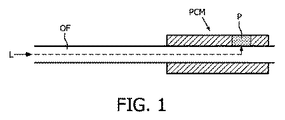
図1は、実施態様の基本的な部分、例えば、医療ガイドワイヤ又はカテーテルの部分の簡略図を例示している。相変化材料PCM(phase change material)の部分が、ここでは細長いデバイスの遠位端部分として例示される、細長いデバイスの長手方向延長部の部分に沿って配置されている。相変化材料PCMの少なくとも部分Pに熱を光学的に提供するよう、光ファイバOFの近位端から相変化材料PCMの少なくとも部分Pに光を伝えるのを可能にするために、光ファイバOFを配置して、光を相変化材料PCMに案内する。これにより、相変化材料PCMのこの部分Pは、1つの剛性値から異なる剛性値に、例えば、「柔」(“soft”)から「硬」(“hard”)に或いは逆の方向に、その剛性を変える。これは細長いデバイスの挙動の制御を可能にし、それは、例えば、FEVAR処置のような、インターベンショナル医療処置(介入医療処置)(interventional medical procedure)中に、ガイドワイヤ又はカテーテルを進める(navigating)のに有利である。光Lを提供する光源及び相変化材料PCMは、相変化材料PCMを1つの相から他の相に変更させるために、十分な光学的な熱が相変化材料に伝えられるのを可能にするよう、整合させられなければならないことが理解されるべきである。 FIG. 1 illustrates a simplified view of the basic parts of an embodiment, for example a medical guidewire or catheter part. Portion of the phase change material PCM (phase change material) is, here is exemplified as the distal end portion of the elongate device, are arranged along a portion of the longitudinal extension of the elongated device. In order to allow the transmission of light from the proximal end of the optical fiber OF to at least part P of the phase change material PCM so as to optically provide heat to at least part P of the phase change material PCM, the optical fiber OF is Position and guide the light to the phase change material PCM. Thereby, this part P of the phase change material PCM is changed from one stiffness value to a different stiffness value, eg from “soft” to “hard” or in the opposite direction. Change the stiffness. This allows control of the behavior of the elongate device, such as navigating a guidewire or catheter during an interventional medical procedure, such as, for example, a FEVAR procedure. Is advantageous. Light source and a phase change material PCM provides light L, in order to change the phase change material PCM from one phase to another phase, sufficient to optical heat to allow the transmitted phase change material It should be understood that they must be aligned.
図1の例示において、光Lが光学要素に達するまで、光Lは光ファイバOF内を長手方向に案内され、光学要素は、光ファイバOFからの光Lを、光ファイバOFを取り囲む相変化材料PCM内に案内する。これを格子(gratings)によって得ることができる。特に、単一の光ファイバOFを使用してカテーテルの多数のセグメントの独立した制御を可能にするために、光ファイバOFがそれぞれの長手方向位置に配置される光学要素を含むのが好ましい。これにより、細長いデバイスのナビゲーション(navigation)の向上を得ることができる。 In the illustration of FIG. 1, until the light L reaches the optical element, the light L is guided longitudinally in the optical fiber OF, which is the phase change material that surrounds the optical fiber OF. Guide to PCM. This can be obtained by gratings . In particular, in order to allow independent control of multiple segments of the catheter using a single optical fiber OF, it is preferred that the optical fiber OF includes optical elements disposed at respective longitudinal positions. This can provide improved navigation of the elongated device.
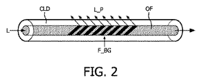
図2は、光ファイバOF内への光Lが一端に加えられる、光ファイバOFの他の略図を例示している。傾斜(tilted)又はブレーズド(blazed)ブラッグ格子(Bragg gratings)F_BGを用いて、光の部分L_Pが光ファイバから外に、即ち、光ファイバOFの長手方向延長部から離れる方向に、例えば、光ファイバOFの長手方向延長部に対して垂直に誘導される。従来的なブラッグ格子におけるブラッグ状態と整合する波長を備える光の反射と同様に、さもなければファイバコア内に反射される光は、部分的に又は全体的に、クラッディングCLD(誘導クラッディングモード)に結合され、そして、部分的に放射モードに結合され、故に、光ファイバOFから取り除かれる。これは、光が光ファイバOFから外に誘導されることによって、周囲の又は隣接して位置付けられる相変化材料(図2に示されていない)内に誘導される、長手方向位置の制御を可能にする。 FIG. 2 illustrates another schematic view of the optical fiber OF where light L into the optical fiber OF is applied at one end. Using tilted or blazed Bragg gratings F_BG, the portion of light L_P is out of the optical fiber, i.e. away from the longitudinal extension of the optical fiber OF, e.g. Guided perpendicular to the longitudinal extension of the OF. Similar to the reflection of light with a wavelength that matches the Bragg state in a conventional Bragg grating, the light that would otherwise be reflected into the fiber core may be partially or fully reflected in a cladding CLD (stimulated cladding mode). ) And partially coupled to the radiation mode and is therefore removed from the optical fiber OF. This allows control of the longitudinal position where light is guided into the surrounding or adjacent positioned phase change material (not shown in FIG. 2) by being guided out of the optical fiber OF To.
図3は、光が光ファイバOFから外に誘導される、よって、隣接して位置付けられる相変化材料(図3には示されていない)内に誘導される位置又は長手方向制御をもたらすために、格子F_BGを用いて光を光ファイバOFから外に誘導する上記原理をどのように拡張し得るかを例示している。光ファイバOF(チャープ格子)の長さに沿って格子間隔を変更することによって、或いは、特異な格子間隔を備える傾斜ブラッグ格子の幾つかのセグメントを有することによって、光が取り出される光ファイバOFの長さに沿う場所は、光ファイバOFの近位端に光を提供する光源の波長を適合させることによって制御され得る。格子F_BGの異なる格子間隔は、短い格子間隔を有する左から1つ目のF_BGから、より長い格子間隔を有する右から1つ目のF_BGに増大するよう、二重矢印の長さによって示されている。これは、加えられる光の波長を変更することを用いて、細長いデバイスの号セインお長手方向位置制御を可能にする。 FIG. 3 is intended to provide position or longitudinal control in which light is directed out of the optical fiber OF, and thus guided in an adjacently positioned phase change material (not shown in FIG. 3). It illustrates how the principle of guiding light out of the optical fiber OF using the grating F_BG can be extended. By changing the grating spacing along the length of the optical fiber OF (chirped grating ) or by having several segments of a tilted Bragg grating with a unique grating spacing of the optical fiber OF from which light is extracted The location along the length can be controlled by adapting the wavelength of the light source that provides light to the proximal end of the optical fiber OF. The different lattice spacings of the lattice F_BG are indicated by the length of the double arrows to increase from the first F_BG from the left with a short lattice spacing to the first F_BG from the right with a longer lattice spacing. Yes. This allows control of the longitudinal position of the elongate device using changing the wavelength of the applied light.
相変化材料を加熱する幾つかのアプローチがある。1つの方法は、クラッディングがクラッディング内に結合させられる光によって加熱されるように、クラッディングが高い吸収係数を有するよう、クラッディングを適合させることである。熱はクラッディングから相変化材料への熱伝導によって移転させられ得る。このためには、クラッディングと相変化材料との間に良好な熱接触があることが不可欠である。他のアプローチは、光がクラッディングモード内に結合されないで放射モードに結合されるよう、光ファイバからクラッディングを取り除くことである。このためには、適切な効果のために、光が検知可能な熱に変換されるよう、光ファイバコアを取り囲む相変化材料が高い吸収係数を有することが重要である。これは、例えば、(黒鉛粒子のような)黒色吸収体をPCMに加えることによって達成され得る。 There are several approaches to heating the phase change material. One way is to adapt the cladding so that the cladding has a high absorption coefficient so that the cladding is heated by the light coupled into the cladding. Heat can be transferred by heat conduction from the cladding to the phase change material. For this, it is essential that there is good thermal contact between the cladding and the phase change material. Another approach is to remove the cladding from the optical fiber so that the light is coupled into the radiation mode without being coupled into the cladding mode. For this purpose, it is important that the phase change material surrounding the optical fiber core has a high absorption coefficient so that light is converted into detectable heat for the proper effect. This can be achieved, for example, by adding a black absorber (such as graphite particles) to the PCM.
図4は、クラッディングCLD内に配置される光ファイバOFを例示しており、クラッディングCLDも、チューブ材料T_M、例えば、高い熱伝導効果を有する、Pebax(登録商標)又は熱伝導性セラミック若しくは金属粒子が充填されたPebax(登録商標)のチューブ内に配置される。相変化材料PCM_1,PCM_2のブロックが、チューブ材料T_M内に埋め込まれ或いは組み込まれる。光ファイバOF内では、相変化材料PCM_1,PCM_2のブロックの長手方向位置に対応する位置に、傾斜格子が示されている。これらの格子は、異なる格子間隔を有することにより、整合する波長によって光を相応して提供することによってPCM_1,PCM_2の相変化をアクティブ化させることの間の選択を可能にするように、示されている。 FIG. 4 illustrates an optical fiber OF placed in a cladding CLD, which can also be a tube material T_M, for example, Pebax® or a thermally conductive ceramic having a high thermal conductivity effect or It is placed in a Pebax® tube filled with metal particles. Blocks of phase change material PCM_1, PCM_2 are embedded or incorporated into the tube material T_M. In the optical fiber OF, an inclined grating is shown at a position corresponding to the longitudinal position of the block of the phase change materials PCM_1 and PCM_2. These gratings are shown to have a different grating spacing so as to allow a choice between activating the phase change of PCM_1, PCM_2 by correspondingly providing light with matching wavelengths. ing.
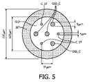
図5は、光ファイバが1つの共通のクラッディングCLD及びジャケットJKT内に配置される複数の光ファイバコアOSS_C,C_STを有する、特定の実施態様の断面を例示している。具体的には、そのようなマルチコア光ファイバは、(複数の)光ファイバコア内のひずみ検知光学要素を用いて光ファイバの形状、よって、そのような光ファイバを位置付ける細長いデバイスの形状の再構築をもたらす、光学形状検知(OSS)として知られる技法において用いられる。 FIG. 5 illustrates a cross-section of a particular embodiment in which the optical fiber has a plurality of optical fiber cores OSS_C, C_ST disposed within a common cladding CLD and jacket JKT. Specifically, such a multi-core optical fiber uses a strain sensing optical element in the optical fiber core (s) to reconstruct the shape of the optical fiber and thus the shape of the elongated device that positions such an optical fiber. Is used in a technique known as optical shape sensing (OSS).
例示する実施例において、相変化材料を用いた細長いデバイスの剛化(stiffening)は、形状検知のためにOSSと組み合わせられる。図示する実施例において、光ファイバコアC_STのうちの3つは、光ファイバのジャケットJKTの外側に配置される相変化材料(図示せず)に光を提供するように配置されるのに対し、4つのコアOSS_Cは、OSSのために配置される。剛性制御装置及びOSSのそのような組み合わせは、コンパクトな(薄い)医療インターベンショナル器具を提供するのに有利である。そのような器具は、使用者が剛化制御構成を用いて器具を進めるのを可能にし、同時に、ナビゲーションは、使用者が例えば器具の先端の3D位置を実時間モニタリングするのを可能にし得るOSS設備を用いて、容易にされる。 In the illustrated embodiment, stiffening of an elongated device using a phase change material is combined with OSS for shape detection. In the illustrated embodiment, three of the optical fiber cores C_ST are arranged to provide light to a phase change material (not shown) that is arranged outside the optical fiber jacket JKT, whereas Four core OSS_Cs are arranged for OSS. Such a combination of stiffness control and OSS is advantageous in providing a compact (thin) medical interventional instrument. Such an instrument allows the user to advance the instrument using a stiffening control configuration, while navigation can allow the user to monitor, for example, the 3D position of the tip of the instrument in real time. Made easy with equipment.
図6は、傾斜格子を備える光ファイバについて実験的に測定された伝送損失TL(transmission loss)のグラフを示している。伝送損失TLスペクトル(波長離調)W_Dは、傾斜格子の(角度間隔0°〜15°内の)様々な傾斜角T_Aに対して示されている。取り出される(trapped out)光の帯域幅及び量は、グラフから分かるように、格子平面の傾斜角T_Aに依存する。これは、好ましくは、特定の範囲の波長の全ての光(ピーク波長+帯域幅)が標的PCMセグメントに沿って均等に分散されるような方法において、傾斜角T_Aを選択し得ることを意味する。また、格子の間隔の間の差は、十分に大きくなければならず、故に、光源の帯域幅も、各セグメントを個々に対処し得るよう、十分に大きくなればならない。 FIG. 6 shows a graph of transmission loss TL (experimental loss) experimentally measured for an optical fiber having a tilted grating . The transmission loss TL spectrum (wavelength detuning) W_D is shown for various tilt angles T_A (within an angular spacing of 0 ° to 15 °) of the tilted grating . The bandwidth and amount of light trapped out depends on the tilt angle T_A of the grating plane, as can be seen from the graph. This means that the tilt angle T_A can preferably be selected in such a way that all light (peak wavelength + bandwidth) in a certain range of wavelengths is evenly distributed along the target PCM segment. . Also, the difference between the grating spacings must be large enough so that the bandwidth of the light source must also be large enough to handle each segment individually.
一般的には、5°〜45°の範囲内の傾斜角が好ましいことがある。一般的には、相変化材料内の相の変化をアクティブ化させるために、400nm〜2000nmの波長範囲内の光が好ましいことがある。 In general, an inclination angle in the range of 5 ° to 45 ° may be preferred. In general, in order to activate the change of phase in the phase change material may be light in the wavelength range of 400nm~2000nm is preferred.
図7は、システム実施態様、例えば、FEVAR処置を行うための医療システムの、部品の単純なブロック図を示している。上で説明したような細長いデバイスを含むガイドワイヤGWは、細長いデバイスの相変化材料の異なる部分の剛化を選択的に可能にするために、好ましくは、ガイドワイヤGWに沿って配置される相変化材料の複数の異なる部分に熱を加えるために配置される、光ファイバを含む。光源C_LSがガイドワイヤGW内の光ファイバの近位端への接続のために配置される。この光源C_LSは、相変化材料の選択的な部分にその剛性を1つの剛性値から異なる剛性値に変えさせるよう、光を提供する働きをする。光源C_LSは、使用者入力U_Iに従ってプロセッサPによって制御される。具体的には、この使用者入力U_Iは、制御デバイスから得られ、使用者がガイドワイヤの選択的な部分の剛性を制御して、例えば、FEVAR処置の部分としての、ナビゲーションを容易にするのを可能にする。プロセッサPは、使用者入力U_Iに従ったガイドワイヤGWの挙動を得るために、ガイドワイヤGW内の相変化材料の所望の部分をアクティブ化させるよう、使用者入力U_Iを、例えば、光源C_LSによって加えられるべき光波長に変換する、制御アルゴリズムを実行する。 FIG. 7 shows a simple block diagram of the components of a system implementation, eg, a medical system for performing FEVAR procedures. A guidewire GW comprising an elongated device as described above is preferably a phase disposed along the guidewire GW to selectively allow stiffening of different portions of the phase change material of the elongated device. It includes an optical fiber that is arranged to apply heat to a plurality of different portions of the change material. A light source C_LS is arranged for connection to the proximal end of the optical fiber in the guidewire GW. The light source C_LS serves to provide light to cause selective portions of the phase change material to change its stiffness from one stiffness value to a different stiffness value. The light source C_LS is controlled by the processor P according to the user input U_I. Specifically, this user input U_I is obtained from a control device and allows the user to control the rigidity of a selective portion of the guidewire to facilitate navigation, for example as part of a FEVAR procedure. Enable. The processor P uses the user input U_I, for example by the light source C_LS, to activate the desired part of the phase change material in the guidewire GW in order to obtain the behavior of the guidewire GW according to the user input U_I. A control algorithm is executed that converts the light wavelength to be added.
具体的には、ガイドワイヤGWは、OSSの適用のために配置される光ファイバコアを含んでよい。そのような場合、システムは、そのようなOSSファイバコアの光学的呼掛け(optical interrogation)のために、従って、ガイドワイヤGWの再構築3D形状の画像の生成のために配置される、光学コンソールを含んでよい。 Specifically, the guidewire GW may include an optical fiber core that is arranged for OSS applications. In such a case, the system is arranged for optical interrogation of such an OSS fiber core and thus for the generation of a reconstructed 3D shape image of the guide wire GW. May be included.
図8は、細長いデバイスを制御する方法の実施態様のステップを示している。第1のステップは、その近位端から細長いデバイスの少なくとも長手方向部分に沿って配置される相変化材料に光を伝送するように配置される光ファイバを含む細長いデバイスP_ELを提供することである。次のステップは、使用者からのナビゲーション入力D_NVを決定することである。使用者入力、例えば、使用者が細長いデバイスの剛化を要望する長手方向位置に応答して、光ファイバに加えられるべき光波長D_LWを決定するステップが行われる。最後に、決定される波長で光ファイバの近位端に光A_LWを提供するステップが行われる。これにより、相変化材料の所望の部分は光学的に加熱されて、相変化材料の所望の部分にその剛性を1つの剛性値から異なる剛性値に変えさせる。 FIG. 8 illustrates the steps of an embodiment of a method for controlling an elongate device. The first step is to provide an elongate device P_EL that includes an optical fiber that is arranged to transmit light from its proximal end to a phase change material that is arranged along at least a longitudinal portion of the elongate device. . The next step is to determine the navigation input D_NV from the user. In response to user input, e.g., a longitudinal position where the user desires stiffening of the elongated device, a step is performed to determine the optical wavelength D_LW to be applied to the optical fiber. Finally, the step of providing light A_LW to the proximal end of the optical fiber at the determined wavelength is performed. This causes the desired portion of the phase change material to be optically heated, causing the desired portion of the phase change material to change its stiffness from one stiffness value to a different stiffness value.
要約すれば、本発明は、相変化材料PCMを光学的に加熱して、その剛性を1つの剛性値から異なる剛性値に変更するために、細長いデバイスに沿って配置される相変化材料PCMへの光の伝送を可能にするように配置される、光ファイバOFを含む、細長いデバイス、例えば、インターベンショナルガイドワイヤ又はカテーテルを提供する。光ファイバに沿って光波長に依存する特異な格子間隔を備える分散させられた傾斜又はブレーズドブラッグ格子を用いることで、選択的な長手方向部分で剛性制御し得るガイドワイヤ又はカテーテルを提供することが可能である。具体的には、例えば、FEVAR処置中の、最適なナビゲーションのために、カテーテル又はガイドワイヤの先端の挙動を制御し得ることが好ましい場合がある。チューブ材料T_Mの内側に配置される相変化材料PCM_1,PCM_2の部分を細長いデバイスの選択的な長手方向部分でアクティブ化させ得る。光学形状検知との組み合わせにおいて、医療インターベンショナル器具の最適な制御を得ることができる。 In summary, the present invention is to heat the phase change material PCM optically, in order to change its stiffness from one stiffness values in different stiffness values, the phase change material PCM disposed along the elongated device An elongate device, such as an interventional guidewire or catheter, is provided that includes an optical fiber OF arranged to allow transmission of light. Providing a guidewire or catheter that can be rigidly controlled in a selective longitudinal section by using a distributed tilted or blazed Bragg grating with a unique grating spacing depending on the light wavelength along the optical fiber Is possible. Specifically, it may be preferable to be able to control the behavior of the tip of the catheter or guidewire, for example, for optimal navigation during the FEVAR procedure. The portion of the phase change material PCM_1, PCM_2 that is disposed inside the tube material T_M may be activated in a selective longitudinal portion of the elongated device. In combination with optical shape detection, optimal control of the medical interventional instrument can be obtained.
本発明が図面中に例示され且つ前述の記述中に詳細に記載されたが、そのような例示及び記述は例示的な又は例証的であると考えられるべきであり、限定的であると考えられるべきでない。本発明は開示の実施態様に限定されない。請求する発明を実施する当業者は、図面、本開示、及び付属の請求項の考察から、開示の実施態様に対する他の変形を理解し且つ行い得る。請求項において、「含む」という用語は、他の要素又はステップを排除せず、単数形は、複数を排除しない。単一のプロセッサ又は他のユニットが、請求項において引用される幾つかの品目の機能を充足してよい。特定の手段が相互に異なる従属項において引用されているという単なる事実は、これらの手段の組み合わせを有利に用い得ないことを示さない。コンピュータプログラムは、他のハードウェアと共に又はその部分として供給される光記憶媒体又はソリッドステート媒体のような、適切な媒体に格納され/分散させられてよいが、インターネット又は他の有線通信システム若しくは無線通信システムのような、他の携帯において分散させられてもよい。請求項中の如何なる参照記号も、範囲を限定するものと解釈されてならない。 While the invention has been illustrated in the drawings and described in detail in the foregoing description, such illustration and description are to be considered illustrative or illustrative and restrictive Should not. The invention is not limited to the disclosed embodiments. Those skilled in the art in practicing the claimed invention may understand and make other variations to the disclosed embodiments from a consideration of the drawings, this disclosure, and the appended claims. In the claims, the term “comprising” does not exclude other elements or steps, and the singular does not exclude the plurality. A single processor or other unit may fulfill the functions of several items recited in the claims. The mere fact that certain measures are recited in mutually different dependent claims does not indicate that a combination of these measured cannot be used to advantage. The computer program may be stored / distributed on any suitable medium, such as an optical storage medium or solid state medium supplied with or as part of other hardware, but the Internet or other wired communication system or wireless It may be distributed in other mobiles, such as a communication system. Any reference signs in the claims should not be construed as limiting the scope.
Claims (11)
− 相変化材料の複数のブロックであって、当該細長いデバイスの長手方向に沿う異なる位置に配置される、相変化材料の複数のブロック、
− 該相変化材料の少なくとも一部分に光学的に熱を提供して、前記相変化材料の前記少なくとも一部分の剛性を1つの剛性値から異なる剛性値に変えるために、光ファイバの近位端から前記相変化材料の前記少なくとも一部分への光の伝送を可能にするよう、前記相変化材料に対して配置される、前記光ファイバとを含み、
前記光ファイバは、前記光ファイバの長手方向に沿う異なる位置に複数の部分を含み、前記光ファイバの前記複数の部分は、前記光ファイバの前記複数の部分のそれぞれで前記光ファイバの長手方向から離れる方向に光を誘導するために配置される、傾斜又はブレーズド格子を備え、
該格子の傾斜角は、特定範囲の波長の光を少なくとも前記光ファイバの前記複数の部分のそれぞれに沿って均等に誘導するよう選択される、
細長いデバイス。 An elongated device,
- the phase change material and a plurality of blocks of, are arranged in different that position along the longitudinal direction of the elongate device, a plurality of blocks of the phase change material,
- providing optically heat to at least a portion of the phase change material, in order to change the stiffness of said at least a portion of the phase change material in different stiffness values from one stiffness values, the proximal end of the optical fiber to allow transmission of light to said at least a portion of the phase change material from being disposed relative to the phase change material, and a said optical fiber,
Wherein the optical fiber comprises a plurality of parts min at different positions along the longitudinal direction of the optical fiber, said plurality of parts of the said optical fiber length of the optical fiber in each of the plurality of portions of said optical fiber is arranged to guide the light to the unsuitable et away direction towards, an inclined or blazed grating,
The tilt angle of the grating is selected to guide light in a specific range of wavelengths evenly along at least each of the plurality of portions of the optical fiber.
An elongated device.
前記細長いデバイスは、
相変化材料の複数のブロックであって、前記細長いデバイスの長手方向に沿う異なる位置に配置される、相変化材料の複数のブロック、
前記相変化材料の少なくとも一部分に熱を光学的に提供して前記相変化材料の前記少なくとも一部分の剛性を1つの剛性値から異なる剛性値に変更させるために、光ファイバの近位端から前記相変化材料の少なくとも一部分に光を伝送するのを可能にするよう、前記相変化材料に対して配置される前記光ファイバであって、前記光ファイバは、前記光ファイバの長手方向に沿う異なる位置に複数の部分を含み、前記光ファイバの前記複数の部分は、前記光ファイバの前記複数の部分のそれぞれで前記光ファイバの長手方向から離れる方向に光を誘導するために配置される傾斜又はブレーズド格子を備え、該格子の傾斜角は、特定範囲の波長の光を少なくとも前記光ファイバの前記複数の部分のそれぞれに沿って均等に誘導するように選択される、前記光ファイバと、
光を提供して前記相変化材料の前記少なくとも一部分の剛性を1つの剛性値から異なる剛性値に変えるために、前記光ファイバの前記近位端への接続のために配置される光源とを含む、
システム。 A system comprising an elongated device,
The elongated device is:
A plurality of blocks of a phase change material, wherein is arranged different that position along the longitudinal direction of the elongated device, a plurality of blocks of the phase change material,
To change to a different stiffness values from one stiffness values rigidity of said at least a portion of the phase change material to provide heat to at least a portion optically of the phase change material, from the proximal end of the optical fiber to allow to transmit light to at least one portion of the phase change material, a said optical fiber is positioned relative to the phase change material, wherein the optical fiber along the longitudinal direction of the optical fiber includes a plurality of portions at different positions, said plurality of parts of the said optical fiber, for guiding the light in the longitudinal direction suited et away direction of the optical fiber their respective in the plurality of portions of said optical fiber Bei give a slope or blazed grating is arranged, the tilt angle of the grating is chosen to evenly guided along each of said plurality of portions of at least said optical fiber light having a wavelength within a specific range , And the optical fiber,
In order to change the stiffness of said at least a portion of the phase change material to provide light to different stiffness values from one stiffness values, and a light source arranged for connection to said proximal end of said optical fiber Including,
system.
その近位端から、相変化材料の複数のブロックであって、少なくとも前記細長いデバイスの長手方向に沿う異なる位置に配置される、相変化材料の複数のブロックに、光を伝送するように配置される光ファイバを含む、前記細長いデバイスを提供するステップであって、前記光ファイバは、前記光ファイバの長手方向に沿う異なる位置に複数の部分を含み、前記光ファイバの前記複数の部分は、前記光ファイバの前記複数の部分のそれぞれで前記光ファイバの長手方向から離れる方向に光を誘導するために配置される傾斜又はブレーズド格子を備え、該格子の傾斜角は、特定範囲の波長の光を少なくとも前記光ファイバの前記複数の部分のそれぞれに沿って均等に誘導するように選択される、ステップと、
前記相変化材料の少なくとも一部分に熱を光学的に提供して、前記相変化材料の前記少なくとも一部分の剛性を1つの剛性値から異なる剛性値に変えるよう、前記光ファイバの近位端に光をもたらすステップとを含む、
方法。 A method for controlling an elongated device comprising:
From its proximal end, a plurality of blocks of the phase change material is disposed along the Hare different positions in the length Tekata direction of at least the elongate device, a plurality of blocks of a phase change material, so as to transmit light comprises an optical fiber disposed, comprising: providing the elongated device, wherein the optical fiber comprises a plurality of parts min at different positions along the longitudinal direction of the optical fiber, said plurality of said optical fiber parts component has an inclined or blazed grating is arranged to guide the light in the longitudinal direction suited et away direction of the optical fiber in each of the plurality of portions of the optical fibers, the inclination angle of the lattice is Selected to direct light of a specific range of wavelengths at least uniformly along each of the plurality of portions of the optical fiber;
Providing heat to at least a portion of the phase change material optically, to vary the stiffness of said at least a portion of the phase change material in different stiffness values from one stiffness value, the proximal end of the optical fiber Providing light,
Method.
Applications Claiming Priority (3)
| Application Number | Priority Date | Filing Date | Title |
|---|---|---|---|
| EP14172894 | 2014-06-18 | ||
| EP14172894.9 | 2014-06-18 | ||
| PCT/EP2015/062104 WO2015193089A1 (en) | 2014-06-18 | 2015-06-01 | Elongated interventional device with variable stiffness |
Publications (3)
| Publication Number | Publication Date |
|---|---|
| JP2017519563A JP2017519563A (en) | 2017-07-20 |
| JP2017519563A5 JP2017519563A5 (en) | 2018-04-05 |
| JP6464202B2 true JP6464202B2 (en) | 2019-02-06 |
Family
ID=51176057
Family Applications (1)
| Application Number | Title | Priority Date | Filing Date |
|---|---|---|---|
| JP2016573022A Expired - Fee Related JP6464202B2 (en) | 2014-06-18 | 2015-06-01 | Elongated interventional device with variable stiffness |
Country Status (5)
| Country | Link |
|---|---|
| US (1) | US9987462B2 (en) |
| EP (1) | EP3157406B1 (en) |
| JP (1) | JP6464202B2 (en) |
| CN (1) | CN106573125B (en) |
| WO (1) | WO2015193089A1 (en) |
Families Citing this family (10)
| Publication number | Priority date | Publication date | Assignee | Title |
|---|---|---|---|---|
| US9987462B2 (en) * | 2014-06-18 | 2018-06-05 | Koninklijke Philips N.V. | Elongated interventional device with variable stiffness |
| US10113537B2 (en) | 2016-04-08 | 2018-10-30 | Ecole Polytechnique Federale De Lausanne (Epfl) | Variable stiffness device and method of manufacturing the same |
| CN107198576B (en) * | 2017-07-17 | 2020-03-03 | 天津大学 | Deployable rigidity-variable snake-shaped carrier for natural orifice surgery |
| CN107280716B (en) * | 2017-07-17 | 2019-11-05 | 天津大学 | A kind of stiffness variable protection sheath and its application method for natural cavity operation |
| EP3449965A1 (en) * | 2017-09-05 | 2019-03-06 | ETH Zurich | Steerable catheter with portions of different stiffness |
| EP3461526A1 (en) * | 2017-09-28 | 2019-04-03 | Koninklijke Philips N.V. | Invasive medical device and manufacturing method |
| CN109893741A (en) * | 2019-03-26 | 2019-06-18 | 武汉理工大学 | A kind of intelligent seal wire based on Fibre Optical Sensor |
| KR102266199B1 (en) * | 2019-10-21 | 2021-06-17 | 한국과학기술연구원 | Rigidity tunable mechanism and endoscope utilizing thermoelectric modules and phase changeable materials at low temperature |
| CN112494778A (en) * | 2020-12-30 | 2021-03-16 | 黄洁 | Deflection structure of interventional catheter |
| CN115166893A (en) * | 2022-08-02 | 2022-10-11 | 苏州国顺激光技术有限公司 | Annular fiber core optical fiber for laser device |
Family Cites Families (25)
| Publication number | Priority date | Publication date | Assignee | Title |
|---|---|---|---|---|
| US4543090A (en) * | 1983-10-31 | 1985-09-24 | Mccoy William C | Steerable and aimable catheter |
| US4934340A (en) * | 1989-06-08 | 1990-06-19 | Hemo Laser Corporation | Device for guiding medical catheters and scopes |
| US5531685A (en) * | 1993-06-11 | 1996-07-02 | Catheter Research, Inc. | Steerable variable stiffness device |
| US5334168A (en) * | 1993-06-11 | 1994-08-02 | Catheter Research, Inc. | Variable shape guide apparatus |
| US5662621A (en) | 1995-07-06 | 1997-09-02 | Scimed Life Systems, Inc. | Guide catheter with shape memory retention |
| US5846247A (en) * | 1996-11-15 | 1998-12-08 | Unsworth; John D. | Shape memory tubular deployment system |
| US6533752B1 (en) | 2000-01-05 | 2003-03-18 | Thomas C Waram | Variable shape guide apparatus |
| US6468203B2 (en) * | 2000-04-03 | 2002-10-22 | Neoguide Systems, Inc. | Steerable endoscope and improved method of insertion |
| JP2002139629A (en) * | 2000-10-31 | 2002-05-17 | Sumitomo Electric Ind Ltd | Optical loss filter |
| JP2005511160A (en) | 2001-07-31 | 2005-04-28 | ベルソン,アミアー | Blood flow guide catheter guide with variable stiffness shaft |
| US7018346B2 (en) * | 2001-12-18 | 2006-03-28 | Scimed Life Systems, Inc. | Guide wire with adjustable flexibility |
| US7245789B2 (en) * | 2002-10-07 | 2007-07-17 | Vascular Imaging Corporation | Systems and methods for minimally-invasive optical-acoustic imaging |
| JP4261166B2 (en) | 2002-11-29 | 2009-04-30 | Hoya株式会社 | Photothermal actuator and device equipped with photothermal actuator |
| FR2863057B1 (en) | 2003-12-02 | 2006-03-24 | Cit Alcatel | PHOTOSENSITIVE OPTICAL GUIDE |
| US7559916B2 (en) | 2004-09-24 | 2009-07-14 | Syntheon, Llc | Catheter with controllable stiffness and method for operating a selective stiffening catheter |
| US7828790B2 (en) * | 2004-12-03 | 2010-11-09 | Boston Scientific Scimed, Inc. | Selectively flexible catheter and method of use |
| US7386203B2 (en) | 2005-06-30 | 2008-06-10 | Lawrence Livermore National Security, Llc | System for diffusing light from an optical fiber or light guide |
| KR100799576B1 (en) * | 2006-08-18 | 2008-01-30 | 한국전자통신연구원 | Optical fiber for out-coupling optical signal and apparatus for detecting optical signal using the same optical fiber |
| US8649847B1 (en) | 2009-05-04 | 2014-02-11 | Intelligent Fiber Optic Systems, Inc. | Steerable shape sensing biopsy needle and catheter |
| CN103153162B (en) * | 2010-09-01 | 2016-06-29 | 皇家飞利浦电子股份有限公司 | The optic shape sensing seal wire that can load afterwards |
| US9164084B2 (en) * | 2012-01-31 | 2015-10-20 | Purdue Research Foundation | Methods for determining aggressiveness of a cancer and treatment thereof |
| RU2622479C2 (en) * | 2012-03-16 | 2017-06-15 | Конинклейке Филипс Н.В. | Optical measurement system for determining position and/or form of associated object |
| WO2013182953A1 (en) * | 2012-06-08 | 2013-12-12 | Koninklijke Philips N.V. | Distributed sensing device for referencing of physiological features |
| JP6320391B2 (en) | 2012-09-28 | 2018-05-09 | コーニンクレッカ フィリップス エヌ ヴェKoninklijke Philips N.V. | Tube and steerable introduction element having the tube |
| US9987462B2 (en) * | 2014-06-18 | 2018-06-05 | Koninklijke Philips N.V. | Elongated interventional device with variable stiffness |
-
2015
- 2015-06-01 US US15/318,730 patent/US9987462B2/en active Active
- 2015-06-01 EP EP15725371.7A patent/EP3157406B1/en active Active
- 2015-06-01 JP JP2016573022A patent/JP6464202B2/en not_active Expired - Fee Related
- 2015-06-01 WO PCT/EP2015/062104 patent/WO2015193089A1/en active Application Filing
- 2015-06-01 CN CN201580032372.5A patent/CN106573125B/en not_active Expired - Fee Related
Also Published As
| Publication number | Publication date |
|---|---|
| CN106573125B (en) | 2020-05-22 |
| US9987462B2 (en) | 2018-06-05 |
| EP3157406B1 (en) | 2019-12-11 |
| JP2017519563A (en) | 2017-07-20 |
| US20170119998A1 (en) | 2017-05-04 |
| WO2015193089A1 (en) | 2015-12-23 |
| EP3157406A1 (en) | 2017-04-26 |
| CN106573125A (en) | 2017-04-19 |
Similar Documents
| Publication | Publication Date | Title |
|---|---|---|
| JP6464202B2 (en) | Elongated interventional device with variable stiffness | |
| US6240231B1 (en) | Variable stiffness fiber optic shaft | |
| US6887235B2 (en) | Variable stiffness heating catheter | |
| US5514128A (en) | Fiber optic guide wire and support catheter therefor | |
| US11701496B2 (en) | Adjustable guidewire | |
| US20130123768A1 (en) | Laser-assisted guidewire having a variable stiffness shaft | |
| AU2002338278A1 (en) | Variable stiffness heating catheter | |
| CN109692039B (en) | Combined laser beam splitter extraction device | |
| US11627882B2 (en) | Esophageal management system for use in displacing an esophagus during a medical procedure | |
| JP2017519563A5 (en) | ||
| US20210378737A1 (en) | Liquid filled ablation catheter with overjacket | |
| US9770297B2 (en) | Energy devices and methods for treating hollow anatomical structures | |
| KR101644072B1 (en) | Apparatus for translumenal circumferential energy delivery | |
| US20160089203A1 (en) | Irradiation device | |
| GB2562526B (en) | Optical energy delivery and sensing apparatus | |
| Taylor et al. | From laser physics to clinical utilization: design and ablative properties of cardiovascular laser catheters | |
| US11877732B1 (en) | Shape sensing biopsy needle | |
| Peshko et al. | Fiber photo-catheters for invasive and less invasive treatment of atrial fibrillation |
Legal Events
| Date | Code | Title | Description |
|---|---|---|---|
| A521 | Request for written amendment filed |
Free format text: JAPANESE INTERMEDIATE CODE: A523 Effective date: 20180219 |
|
| A621 | Written request for application examination |
Free format text: JAPANESE INTERMEDIATE CODE: A621 Effective date: 20180219 |
|
| A871 | Explanation of circumstances concerning accelerated examination |
Free format text: JAPANESE INTERMEDIATE CODE: A871 Effective date: 20180219 |
|
| A975 | Report on accelerated examination |
Free format text: JAPANESE INTERMEDIATE CODE: A971005 Effective date: 20180312 |
|
| A131 | Notification of reasons for refusal |
Free format text: JAPANESE INTERMEDIATE CODE: A131 Effective date: 20180320 |
|
| A521 | Request for written amendment filed |
Free format text: JAPANESE INTERMEDIATE CODE: A523 Effective date: 20180613 |
|
| A131 | Notification of reasons for refusal |
Free format text: JAPANESE INTERMEDIATE CODE: A131 Effective date: 20180904 |
|
| A521 | Request for written amendment filed |
Free format text: JAPANESE INTERMEDIATE CODE: A523 Effective date: 20181128 |
|
| TRDD | Decision of grant or rejection written | ||
| A01 | Written decision to grant a patent or to grant a registration (utility model) |
Free format text: JAPANESE INTERMEDIATE CODE: A01 Effective date: 20181211 |
|
| A61 | First payment of annual fees (during grant procedure) |
Free format text: JAPANESE INTERMEDIATE CODE: A61 Effective date: 20190107 |
|
| R150 | Certificate of patent or registration of utility model |
Ref document number: 6464202 Country of ref document: JP Free format text: JAPANESE INTERMEDIATE CODE: R150 |
|
| R250 | Receipt of annual fees |
Free format text: JAPANESE INTERMEDIATE CODE: R250 |
|
| LAPS | Cancellation because of no payment of annual fees |