JP6464015B2 - Connecting element for pressure tank and pressure tank - Google Patents
Connecting element for pressure tank and pressure tank Download PDFInfo
- Publication number
- JP6464015B2 JP6464015B2 JP2015081676A JP2015081676A JP6464015B2 JP 6464015 B2 JP6464015 B2 JP 6464015B2 JP 2015081676 A JP2015081676 A JP 2015081676A JP 2015081676 A JP2015081676 A JP 2015081676A JP 6464015 B2 JP6464015 B2 JP 6464015B2
- Authority
- JP
- Japan
- Prior art keywords
- tank
- tank wall
- pressure tank
- connecting element
- plug
- Prior art date
- Legal status (The legal status is an assumption and is not a legal conclusion. Google has not performed a legal analysis and makes no representation as to the accuracy of the status listed.)
- Active
Links
- 239000002184 metal Substances 0.000 claims description 37
- 230000013011 mating Effects 0.000 claims description 36
- 229920003023 plastic Polymers 0.000 claims description 17
- 239000000835 fiber Substances 0.000 claims description 12
- 238000004804 winding Methods 0.000 claims description 8
- 238000000071 blow moulding Methods 0.000 claims 1
- ZQESQBVNDBLWAM-WMZHIEFXSA-N n-[(3s,4r)-1-[2-(4-isothiocyanatophenyl)ethyl]-3-methylpiperidin-4-yl]-n-phenylpropanamide Chemical compound C([C@H]([C@H](C1)C)N(C(=O)CC)C=2C=CC=CC=2)CN1CCC1=CC=C(N=C=S)C=C1 ZQESQBVNDBLWAM-WMZHIEFXSA-N 0.000 claims 1
- 238000003780 insertion Methods 0.000 description 17
- 230000037431 insertion Effects 0.000 description 17
- 238000007789 sealing Methods 0.000 description 10
- UFHFLCQGNIYNRP-UHFFFAOYSA-N Hydrogen Chemical compound [H][H] UFHFLCQGNIYNRP-UHFFFAOYSA-N 0.000 description 6
- 239000002131 composite material Substances 0.000 description 6
- 239000001257 hydrogen Substances 0.000 description 6
- 229910052739 hydrogen Inorganic materials 0.000 description 6
- 229920001903 high density polyethylene Polymers 0.000 description 4
- 239000007788 liquid Substances 0.000 description 4
- 238000010586 diagram Methods 0.000 description 3
- 238000004519 manufacturing process Methods 0.000 description 3
- 239000000853 adhesive Substances 0.000 description 2
- 230000001070 adhesive effect Effects 0.000 description 2
- 239000012530 fluid Substances 0.000 description 2
- 238000009434 installation Methods 0.000 description 2
- VNWKTOKETHGBQD-UHFFFAOYSA-N methane Chemical compound C VNWKTOKETHGBQD-UHFFFAOYSA-N 0.000 description 2
- 230000015556 catabolic process Effects 0.000 description 1
- 239000000567 combustion gas Substances 0.000 description 1
- 238000002485 combustion reaction Methods 0.000 description 1
- 238000010276 construction Methods 0.000 description 1
- 238000006731 degradation reaction Methods 0.000 description 1
- 230000001419 dependent effect Effects 0.000 description 1
- 238000010101 extrusion blow moulding Methods 0.000 description 1
- 239000000446 fuel Substances 0.000 description 1
- 239000007789 gas Substances 0.000 description 1
- 230000001771 impaired effect Effects 0.000 description 1
- 230000014759 maintenance of location Effects 0.000 description 1
- 239000003345 natural gas Substances 0.000 description 1
- 238000012856 packing Methods 0.000 description 1
- 230000001681 protective effect Effects 0.000 description 1
- 230000003014 reinforcing effect Effects 0.000 description 1
- 239000011347 resin Substances 0.000 description 1
- 229920005989 resin Polymers 0.000 description 1
- 230000006641 stabilisation Effects 0.000 description 1
- 238000011105 stabilization Methods 0.000 description 1
- 239000011232 storage material Substances 0.000 description 1
- 239000000126 substance Substances 0.000 description 1
- 230000007704 transition Effects 0.000 description 1
Images


Classifications
-
- F—MECHANICAL ENGINEERING; LIGHTING; HEATING; WEAPONS; BLASTING
- F17—STORING OR DISTRIBUTING GASES OR LIQUIDS
- F17C—VESSELS FOR CONTAINING OR STORING COMPRESSED, LIQUEFIED OR SOLIDIFIED GASES; FIXED-CAPACITY GAS-HOLDERS; FILLING VESSELS WITH, OR DISCHARGING FROM VESSELS, COMPRESSED, LIQUEFIED, OR SOLIDIFIED GASES
- F17C13/00—Details of vessels or of the filling or discharging of vessels
- F17C13/06—Closures, e.g. cap, breakable member
-
- F—MECHANICAL ENGINEERING; LIGHTING; HEATING; WEAPONS; BLASTING
- F17—STORING OR DISTRIBUTING GASES OR LIQUIDS
- F17C—VESSELS FOR CONTAINING OR STORING COMPRESSED, LIQUEFIED OR SOLIDIFIED GASES; FIXED-CAPACITY GAS-HOLDERS; FILLING VESSELS WITH, OR DISCHARGING FROM VESSELS, COMPRESSED, LIQUEFIED, OR SOLIDIFIED GASES
- F17C2201/00—Vessel construction, in particular geometry, arrangement or size
- F17C2201/01—Shape
- F17C2201/0104—Shape cylindrical
- F17C2201/0109—Shape cylindrical with exteriorly curved end-piece
-
- F—MECHANICAL ENGINEERING; LIGHTING; HEATING; WEAPONS; BLASTING
- F17—STORING OR DISTRIBUTING GASES OR LIQUIDS
- F17C—VESSELS FOR CONTAINING OR STORING COMPRESSED, LIQUEFIED OR SOLIDIFIED GASES; FIXED-CAPACITY GAS-HOLDERS; FILLING VESSELS WITH, OR DISCHARGING FROM VESSELS, COMPRESSED, LIQUEFIED, OR SOLIDIFIED GASES
- F17C2201/00—Vessel construction, in particular geometry, arrangement or size
- F17C2201/05—Size
- F17C2201/056—Small (<1 m3)
-
- F—MECHANICAL ENGINEERING; LIGHTING; HEATING; WEAPONS; BLASTING
- F17—STORING OR DISTRIBUTING GASES OR LIQUIDS
- F17C—VESSELS FOR CONTAINING OR STORING COMPRESSED, LIQUEFIED OR SOLIDIFIED GASES; FIXED-CAPACITY GAS-HOLDERS; FILLING VESSELS WITH, OR DISCHARGING FROM VESSELS, COMPRESSED, LIQUEFIED, OR SOLIDIFIED GASES
- F17C2201/00—Vessel construction, in particular geometry, arrangement or size
- F17C2201/05—Size
- F17C2201/058—Size portable (<30 l)
-
- F—MECHANICAL ENGINEERING; LIGHTING; HEATING; WEAPONS; BLASTING
- F17—STORING OR DISTRIBUTING GASES OR LIQUIDS
- F17C—VESSELS FOR CONTAINING OR STORING COMPRESSED, LIQUEFIED OR SOLIDIFIED GASES; FIXED-CAPACITY GAS-HOLDERS; FILLING VESSELS WITH, OR DISCHARGING FROM VESSELS, COMPRESSED, LIQUEFIED, OR SOLIDIFIED GASES
- F17C2203/00—Vessel construction, in particular walls or details thereof
- F17C2203/06—Materials for walls or layers thereof; Properties or structures of walls or their materials
- F17C2203/0602—Wall structures; Special features thereof
- F17C2203/0604—Liners
-
- F—MECHANICAL ENGINEERING; LIGHTING; HEATING; WEAPONS; BLASTING
- F17—STORING OR DISTRIBUTING GASES OR LIQUIDS
- F17C—VESSELS FOR CONTAINING OR STORING COMPRESSED, LIQUEFIED OR SOLIDIFIED GASES; FIXED-CAPACITY GAS-HOLDERS; FILLING VESSELS WITH, OR DISCHARGING FROM VESSELS, COMPRESSED, LIQUEFIED, OR SOLIDIFIED GASES
- F17C2203/00—Vessel construction, in particular walls or details thereof
- F17C2203/06—Materials for walls or layers thereof; Properties or structures of walls or their materials
- F17C2203/0602—Wall structures; Special features thereof
- F17C2203/0612—Wall structures
- F17C2203/0614—Single wall
- F17C2203/0619—Single wall with two layers
-
- F—MECHANICAL ENGINEERING; LIGHTING; HEATING; WEAPONS; BLASTING
- F17—STORING OR DISTRIBUTING GASES OR LIQUIDS
- F17C—VESSELS FOR CONTAINING OR STORING COMPRESSED, LIQUEFIED OR SOLIDIFIED GASES; FIXED-CAPACITY GAS-HOLDERS; FILLING VESSELS WITH, OR DISCHARGING FROM VESSELS, COMPRESSED, LIQUEFIED, OR SOLIDIFIED GASES
- F17C2203/00—Vessel construction, in particular walls or details thereof
- F17C2203/06—Materials for walls or layers thereof; Properties or structures of walls or their materials
- F17C2203/0634—Materials for walls or layers thereof
- F17C2203/0658—Synthetics
- F17C2203/0663—Synthetics in form of fibers or filaments
-
- F—MECHANICAL ENGINEERING; LIGHTING; HEATING; WEAPONS; BLASTING
- F17—STORING OR DISTRIBUTING GASES OR LIQUIDS
- F17C—VESSELS FOR CONTAINING OR STORING COMPRESSED, LIQUEFIED OR SOLIDIFIED GASES; FIXED-CAPACITY GAS-HOLDERS; FILLING VESSELS WITH, OR DISCHARGING FROM VESSELS, COMPRESSED, LIQUEFIED, OR SOLIDIFIED GASES
- F17C2205/00—Vessel construction, in particular mounting arrangements, attachments or identifications means
- F17C2205/03—Fluid connections, filters, valves, closure means or other attachments
- F17C2205/0302—Fittings, valves, filters, or components in connection with the gas storage device
- F17C2205/0305—Bosses, e.g. boss collars
-
- F—MECHANICAL ENGINEERING; LIGHTING; HEATING; WEAPONS; BLASTING
- F17—STORING OR DISTRIBUTING GASES OR LIQUIDS
- F17C—VESSELS FOR CONTAINING OR STORING COMPRESSED, LIQUEFIED OR SOLIDIFIED GASES; FIXED-CAPACITY GAS-HOLDERS; FILLING VESSELS WITH, OR DISCHARGING FROM VESSELS, COMPRESSED, LIQUEFIED, OR SOLIDIFIED GASES
- F17C2221/00—Handled fluid, in particular type of fluid
- F17C2221/01—Pure fluids
- F17C2221/012—Hydrogen
-
- F—MECHANICAL ENGINEERING; LIGHTING; HEATING; WEAPONS; BLASTING
- F17—STORING OR DISTRIBUTING GASES OR LIQUIDS
- F17C—VESSELS FOR CONTAINING OR STORING COMPRESSED, LIQUEFIED OR SOLIDIFIED GASES; FIXED-CAPACITY GAS-HOLDERS; FILLING VESSELS WITH, OR DISCHARGING FROM VESSELS, COMPRESSED, LIQUEFIED, OR SOLIDIFIED GASES
- F17C2221/00—Handled fluid, in particular type of fluid
- F17C2221/03—Mixtures
- F17C2221/032—Hydrocarbons
- F17C2221/033—Methane, e.g. natural gas, CNG, LNG, GNL, GNC, PLNG
-
- F—MECHANICAL ENGINEERING; LIGHTING; HEATING; WEAPONS; BLASTING
- F17—STORING OR DISTRIBUTING GASES OR LIQUIDS
- F17C—VESSELS FOR CONTAINING OR STORING COMPRESSED, LIQUEFIED OR SOLIDIFIED GASES; FIXED-CAPACITY GAS-HOLDERS; FILLING VESSELS WITH, OR DISCHARGING FROM VESSELS, COMPRESSED, LIQUEFIED, OR SOLIDIFIED GASES
- F17C2223/00—Handled fluid before transfer, i.e. state of fluid when stored in the vessel or before transfer from the vessel
- F17C2223/01—Handled fluid before transfer, i.e. state of fluid when stored in the vessel or before transfer from the vessel characterised by the phase
- F17C2223/0107—Single phase
- F17C2223/0123—Single phase gaseous, e.g. CNG, GNC
-
- F—MECHANICAL ENGINEERING; LIGHTING; HEATING; WEAPONS; BLASTING
- F17—STORING OR DISTRIBUTING GASES OR LIQUIDS
- F17C—VESSELS FOR CONTAINING OR STORING COMPRESSED, LIQUEFIED OR SOLIDIFIED GASES; FIXED-CAPACITY GAS-HOLDERS; FILLING VESSELS WITH, OR DISCHARGING FROM VESSELS, COMPRESSED, LIQUEFIED, OR SOLIDIFIED GASES
- F17C2223/00—Handled fluid before transfer, i.e. state of fluid when stored in the vessel or before transfer from the vessel
- F17C2223/01—Handled fluid before transfer, i.e. state of fluid when stored in the vessel or before transfer from the vessel characterised by the phase
- F17C2223/0146—Two-phase
- F17C2223/0153—Liquefied gas, e.g. LPG, GPL
- F17C2223/0161—Liquefied gas, e.g. LPG, GPL cryogenic, e.g. LNG, GNL, PLNG
-
- F—MECHANICAL ENGINEERING; LIGHTING; HEATING; WEAPONS; BLASTING
- F17—STORING OR DISTRIBUTING GASES OR LIQUIDS
- F17C—VESSELS FOR CONTAINING OR STORING COMPRESSED, LIQUEFIED OR SOLIDIFIED GASES; FIXED-CAPACITY GAS-HOLDERS; FILLING VESSELS WITH, OR DISCHARGING FROM VESSELS, COMPRESSED, LIQUEFIED, OR SOLIDIFIED GASES
- F17C2223/00—Handled fluid before transfer, i.e. state of fluid when stored in the vessel or before transfer from the vessel
- F17C2223/03—Handled fluid before transfer, i.e. state of fluid when stored in the vessel or before transfer from the vessel characterised by the pressure level
- F17C2223/033—Small pressure, e.g. for liquefied gas
-
- F—MECHANICAL ENGINEERING; LIGHTING; HEATING; WEAPONS; BLASTING
- F17—STORING OR DISTRIBUTING GASES OR LIQUIDS
- F17C—VESSELS FOR CONTAINING OR STORING COMPRESSED, LIQUEFIED OR SOLIDIFIED GASES; FIXED-CAPACITY GAS-HOLDERS; FILLING VESSELS WITH, OR DISCHARGING FROM VESSELS, COMPRESSED, LIQUEFIED, OR SOLIDIFIED GASES
- F17C2223/00—Handled fluid before transfer, i.e. state of fluid when stored in the vessel or before transfer from the vessel
- F17C2223/03—Handled fluid before transfer, i.e. state of fluid when stored in the vessel or before transfer from the vessel characterised by the pressure level
- F17C2223/036—Very high pressure (>80 bar)
-
- F—MECHANICAL ENGINEERING; LIGHTING; HEATING; WEAPONS; BLASTING
- F17—STORING OR DISTRIBUTING GASES OR LIQUIDS
- F17C—VESSELS FOR CONTAINING OR STORING COMPRESSED, LIQUEFIED OR SOLIDIFIED GASES; FIXED-CAPACITY GAS-HOLDERS; FILLING VESSELS WITH, OR DISCHARGING FROM VESSELS, COMPRESSED, LIQUEFIED, OR SOLIDIFIED GASES
- F17C2260/00—Purposes of gas storage and gas handling
- F17C2260/03—Dealing with losses
- F17C2260/035—Dealing with losses of fluid
- F17C2260/036—Avoiding leaks
-
- F—MECHANICAL ENGINEERING; LIGHTING; HEATING; WEAPONS; BLASTING
- F17—STORING OR DISTRIBUTING GASES OR LIQUIDS
- F17C—VESSELS FOR CONTAINING OR STORING COMPRESSED, LIQUEFIED OR SOLIDIFIED GASES; FIXED-CAPACITY GAS-HOLDERS; FILLING VESSELS WITH, OR DISCHARGING FROM VESSELS, COMPRESSED, LIQUEFIED, OR SOLIDIFIED GASES
- F17C2270/00—Applications
- F17C2270/01—Applications for fluid transport or storage
- F17C2270/0165—Applications for fluid transport or storage on the road
- F17C2270/0168—Applications for fluid transport or storage on the road by vehicles
- F17C2270/0178—Cars
-
- F—MECHANICAL ENGINEERING; LIGHTING; HEATING; WEAPONS; BLASTING
- F17—STORING OR DISTRIBUTING GASES OR LIQUIDS
- F17C—VESSELS FOR CONTAINING OR STORING COMPRESSED, LIQUEFIED OR SOLIDIFIED GASES; FIXED-CAPACITY GAS-HOLDERS; FILLING VESSELS WITH, OR DISCHARGING FROM VESSELS, COMPRESSED, LIQUEFIED, OR SOLIDIFIED GASES
- F17C2270/00—Applications
- F17C2270/01—Applications for fluid transport or storage
- F17C2270/0165—Applications for fluid transport or storage on the road
- F17C2270/0184—Fuel cells
-
- Y—GENERAL TAGGING OF NEW TECHNOLOGICAL DEVELOPMENTS; GENERAL TAGGING OF CROSS-SECTIONAL TECHNOLOGIES SPANNING OVER SEVERAL SECTIONS OF THE IPC; TECHNICAL SUBJECTS COVERED BY FORMER USPC CROSS-REFERENCE ART COLLECTIONS [XRACs] AND DIGESTS
- Y02—TECHNOLOGIES OR APPLICATIONS FOR MITIGATION OR ADAPTATION AGAINST CLIMATE CHANGE
- Y02E—REDUCTION OF GREENHOUSE GAS [GHG] EMISSIONS, RELATED TO ENERGY GENERATION, TRANSMISSION OR DISTRIBUTION
- Y02E60/00—Enabling technologies; Technologies with a potential or indirect contribution to GHG emissions mitigation
- Y02E60/30—Hydrogen technology
- Y02E60/32—Hydrogen storage
Description
本発明は、圧力タンク用接続要素に関するものである。さらに本発明は、この種の接続要素を含んでいる圧力タンクに関する。圧力タンクは特に低温圧力タンクまたは高圧タンクであり、圧力タンクには有利には水素を供給可能である。圧力タンクは有利には自動車内での使用のために設けられている。 The present invention relates to a connecting element for a pressure tank. The invention further relates to a pressure tank comprising such a connection element. The pressure tank is in particular a low-temperature pressure tank or a high-pressure tank, which can advantageously be supplied with hydrogen. The pressure tank is preferably provided for use in a motor vehicle.
技術水準から、特に水素を供給可能なタンクが知られている。水素が金属タンク内に貯留されている場合に通常発生する金属劣化を阻止するため、水素タンクがプラスチックから作製されることがある。この種のプラスチックタンクには接続要素を挿入可能であり、該接続要素を介してタンクを密閉可能である。この場合接続要素はさらにタンクを充填させ、空にさせるようでなければならない。この種の接続要素は通常金属から作製されている。よって、プラスチックタンクと金属密閉部とのコンビネーションが必要である。 From the state of the art, tanks capable of supplying hydrogen in particular are known. In order to prevent metal degradation that normally occurs when hydrogen is stored in a metal tank, the hydrogen tank may be made of plastic. A connecting element can be inserted into this type of plastic tank, and the tank can be sealed via the connecting element. In this case, the connecting element must also fill the tank and empty it. This type of connecting element is usually made of metal. Therefore, a combination of a plastic tank and a metal sealing part is necessary.
この種の配置構成をたとえば特許文献1が開示している。この文献は圧力容器を示しており、その開口部は中空筒状の首部へ連続的に移行している。中空筒状の首部は、同様に中空筒状の極片によって取り囲まれ、その際圧力容器の首部も極片も外側へ円錐状に拡大している。極片には、最終的に気密な弁を配置することができる。しかしながら、これには、プラスチックタンクのプラスチック壁が円錐形状を有していなければならないという欠点がある。 For example, Patent Document 1 discloses this type of arrangement. This document shows a pressure vessel whose opening continuously transitions to a hollow cylindrical neck. The hollow cylindrical neck is similarly surrounded by a hollow cylindrical pole piece, in which case the neck and pole piece of the pressure vessel are conically expanded outward. Finally, an airtight valve can be arranged on the pole piece. However, this has the disadvantage that the plastic wall of the plastic tank must have a conical shape.
特許文献2から複合圧力容器が知られている。この容器は、プラスチックタンクと、該プラスチックタンクを補強するための繊維複合材料から成る巻回部(ライナー)とを含んでいる。首片はライナー内へ挿入され、クランプリングを用いてライナーに固定される。しかしながら、ここでは、クランプリングが首片の中に内面と面一になるようにねじ止めされ、このことはタンク弁のねじ込みを困難にさせる。 A composite pressure vessel is known from US Pat. This container includes a plastic tank and a winding portion (liner) made of a fiber composite material for reinforcing the plastic tank. The neck piece is inserted into the liner and secured to the liner using a clamp ring. Here, however, the clamp ring is screwed into the neck piece to be flush with the inner surface, which makes it difficult to screw the tank valve.
特許文献3からは、ガス状媒体を貯留するための圧力容器が知られている。この圧力容器は、繊維複合材料から成る巻回部と、プラスチックタンクと、支持リングを備えた接続フランジとを有している。しかしながら、この場合、付加的な弾性要素が必要であり、必要な取り付けを非常に面倒にさせる。
From
さらに、特許文献4から、Oリングパッキンを含む弁体と、金属リングと、プラスチックタンクとから成るタンクが知られている。さらに、プラスチックタンク(ライナー)を金属リングに押圧させ、ライナーを金属リングに対し密封させるために、弾性クランプ要素が使用される。しかしながら、ライナー内にねじ山があり、機械的負荷が強すぎると、このねじ山が破損することがある。さらに、このねじ山はプラスチックライナーの製造を困難にさせ、高価にさせる。 Furthermore, Patent Document 4 discloses a tank including a valve body including an O-ring packing, a metal ring, and a plastic tank. In addition, elastic clamping elements are used to force the plastic tank (liner) against the metal ring and seal the liner against the metal ring. However, if there is a thread in the liner and the mechanical load is too strong, this thread can break. Furthermore, this thread makes the production of plastic liners difficult and expensive.
さらに、特許文献5から、液状媒体またはガス状媒体を貯留するための圧力容器が知られている。この圧力容器の本体は、回転対称なカラーを備えたプラスチックから成り、カラーの中に圧力弁の一部分が挿着されている。カラーの外側には、金属から成る接続片がある。この場合、圧力弁は雄ねじを備え、この雄ねじが、接続片の、本体とは逆の側にある端部にねじ込まれている。本体とフランジとは、少なくとも部分的に、繊維複合材から成る保護カバーによって取り囲まれている。 Furthermore, from Patent Document 5, a pressure vessel for storing a liquid medium or a gaseous medium is known. The main body of the pressure vessel is made of plastic with a rotationally symmetric collar, and a portion of the pressure valve is inserted into the collar. On the outside of the collar is a connecting piece made of metal. In this case, the pressure valve is provided with a male screw, which is screwed into the end of the connecting piece on the side opposite to the main body. The main body and the flange are at least partially surrounded by a protective cover made of a fiber composite material.
特許文献6から、プラスチックライナー(樹脂ライナー)を含んだ、流体を貯留するための圧力容器が知られている。このプラスチックライナーは、互いに別々に製造された複数の部分から構成されている。しかしながら、プラスチックライナーの複数部分からなる構成様式は、圧力タンクの組み立てを著しく困難にする。 From Patent Document 6, a pressure vessel for storing a fluid including a plastic liner (resin liner) is known. This plastic liner is composed of a plurality of parts manufactured separately from each other. However, the multi-part construction of the plastic liner makes the pressure tank assembly significantly difficult.
最後に、特許文献7から、液状媒体およびガス状媒体の貯留に適した圧力容器が知られている。この圧力容器は、少なくとも1つの首部材を備えたプラスチック内側容器から成っている。この首部材は接続アーマチュアを受容する手段を備えている。圧力容器は、容器首部の少なくとも一部を形成するインサートであって、首部材と挿着されるアーマチュアとの間の密封部を形成している前記インサートを含んでいる。しかしこれは取り付け後に安定性がなく、その結果安定化のためにタンク弁を繊維複合材および接着剤で取り囲まなければならない。この時はじめてタンク弁は、よって圧力タンクは液状またはガス状の貯留物質に対し密封性を有するに至る。
Finally, from
本発明の課題は、製造が簡単でコスト上好ましく、圧力タンクの確実で信頼性のある密封を可能にする圧力タンク用接続要素を提供することである。さらに、これに対応する圧力タンクを提供することも本発明の課題である。 The object of the present invention is to provide a connecting element for a pressure tank which is simple to manufacture and is cost-effective and which allows a reliable and reliable sealing of the pressure tank. Furthermore, it is also an object of the present invention to provide a pressure tank corresponding to this.
この課題は、請求項1の構成によって解決される。すなわち前記課題は、圧力タンクの開口部に挿着可能な圧力タンク用接続要素によって解決される。接続要素は、栓要素と、該栓要素と結合可能な嵌め合い要素と、該嵌め合い要素と作用結合しているねじ止めナットとを含んでいる。この場合、嵌め合い要素が栓要素を少なくとも部分的に取り囲むように構成されている。栓要素の外面と嵌め合い要素の内面とは、ねじ止めナットのねじ込み方向とは逆の方向に先細りになっている先細りの繰り抜き部を形成している。この繰り抜き部に圧力タンクのタンク壁を挿着可能である。すなわち、ねじ止めナットをねじ込むことによって嵌め合い要素が圧力タンクのタンク壁に対し押圧されることで、先細りの繰り抜き部によりタンク壁は有利には栓要素と嵌め合い要素との間で押圧され、その結果タンク壁は繰り抜き部内でクランプ可能である。この場合、タンク壁のクランプは有利には栓要素を嵌め合い要素の中へ挿入することによって行われる。 This problem is solved by the structure of claim 1. That is, the problem is solved by a pressure tank connecting element that can be inserted into the opening of the pressure tank. The connecting element includes a plug element, a mating element that can be coupled to the plug element, and a screw nut that is operatively coupled to the mating element . In this case, the mating element is configured to at least partially surround the plug element. The outer surface of the plug element and the inner surface of the mating element form a tapered withdrawal portion that tapers in a direction opposite to the screwing direction of the screw nut . The tank wall of the pressure tank can be inserted into this pull-out portion. That is, the fitting element is pressed against the tank wall of the pressure tank by screwing a screw nut, so that the tank wall is advantageously pressed between the plug element and the fitting element by the tapered withdrawal portion. As a result, the tank wall can be clamped in the withdrawal part. In this case, clamping of the tank wall is preferably effected by inserting the plug element into the mating element.
従属項は、本発明の有利な更なる構成を内容としている。 The dependent claims contain advantageous further configurations of the invention.
有利には、嵌め合い要素は金属円錐部および/または円錐状の表面を備えた金属挿入部材を含んでいる。先細りの繰り抜き部は円錐形状によって形成されている。これによってタンク壁は円錐状の表面および/または金属円錐部によって栓要素に対し押圧可能である。 Advantageously, the mating element comprises a metal insert with a metal cone and / or a conical surface. The tapered withdrawal portion is formed in a conical shape. This allows the tank wall to be pressed against the plug element by means of a conical surface and / or a metal cone.
1つの有利な実施態様では、栓要素は、少なくとも部分的に円錐状の表面を有するように構成されている。同様に、円錐状の表面により先細りの繰り抜き部が形成される。特に有利には、栓要素も嵌め合い要素も円錐状の表面を備えるように構成されており、その結果先細り繰り抜き部はいわば嵌め合い要素と栓要素とによって形成されている。さらに、栓要素および/または嵌め合い要素の円錐状表面を設けることにより、タンク壁のクランプの程度を調整できるので有利である。それ故、有利には、栓要素と嵌め合い要素とは、これらが結合されているときに互いに変位可能に位置決め可能である。 In one advantageous embodiment, the plug element is configured to have an at least partly conical surface. Similarly, a tapered withdrawal portion is formed by the conical surface. Particularly advantageously, both the plug element and the mating element are provided with a conical surface, so that the tapered withdrawal is formed by the mating element and the plug element. Furthermore, the provision of a conical surface of the plug element and / or the mating element is advantageous because the degree of clamping of the tank wall can be adjusted. Thus, advantageously, the plug element and the mating element are displaceably positionable relative to each other when they are joined.
さらに、有利には、栓要素は少なくとも1つの雄ねじを有するように構成されている。少なくとも1つの雄ねじには、第1の有利な実施態様では、嵌め合い要素がねじ止めされている。従って嵌め合い要素は栓要素と結合され、その際嵌め合い要素とは栓要素とは互いに相対的に位置決め可能である。これとは択一的に、または、これに加えて、第2の有利な実施態様として、ねじ止めナットが設けられている。ねじ止めナットは有利には嵌め合い要素と作用結合され、その結果ねじ止め要素のねじ込みおよび/または取り外しは嵌め合い要素を栓要素に対し相対的に変位させる。従って、嵌め合い要素も栓要素に対し相対的に位置決め可能である。第2実施態様では、有利には、嵌め合い要素は、該嵌め合い要素を栓要素の雄ねじにねじ止め可能にするための固有のねじ山を有していない。従って、嵌め合い要素は非常に簡潔であり、コスト上好ましく製造可能である。 Furthermore, the plug element is advantageously configured to have at least one external thread. In the first advantageous embodiment, the mating element is screwed onto the at least one male thread. The mating element is thus coupled with the plug element, wherein the mating element is positionable relative to the plug element. As an alternative or in addition, a screw nut is provided as a second advantageous embodiment. The screw nut is preferably operatively coupled with the mating element, so that screwing and / or removal of the screw element displaces the mating element relative to the plug element. Thus, the mating element can also be positioned relative to the plug element. In the second embodiment, advantageously, the mating element does not have an inherent thread for enabling the mating element to be screwed onto the male thread of the plug element. Therefore, the mating element is very simple and can be manufactured preferably in terms of cost.
栓要素は、有利には、凹部を有している。タンク壁は嵌め合い要素によって栓要素の凹部内へ圧入可能である。特に、タンク壁の端部領域が凹部内へ圧入可能である。さらに、有利には、凹部が設けられるのは、先細りの繰り抜き部の最小サイズ部である。この領域で最大クランプ作用を達成可能であり、これによってタンク壁が凹部内部で固定可能である。 The plug element advantageously has a recess. The tank wall can be pressed into the recess of the plug element by means of a mating element. In particular, the end region of the tank wall can be pressed into the recess. Furthermore, advantageously, the recess is provided in the smallest size part of the tapered withdrawal part. Maximum clamping action can be achieved in this region, so that the tank wall can be fixed inside the recess.
さらに、有利には、栓要素はスリーブ形状を有している。前述したように栓要素が少なくとも1つの雄ねじを有している場合、この雄ねじはスリーブ状の栓要素の外面に配置される。特に有利には、スリーブ状の栓要素はさらに雌ねじを備え、その結果他の構成要素を栓要素にねじ込み可能である。特に有利には、この種の雌ねじには圧力タンク用接続要素をねじ込み可能である。このように接続要素は、有利には圧力タンクを密閉するため、および/または、圧力タンクを空にするため、および/または、圧力タンクを充填するために用いられる。 Furthermore, advantageously, the plug element has a sleeve shape. If the plug element has at least one male thread as described above, this male thread is arranged on the outer surface of the sleeve-shaped plug element. Particularly advantageously, the sleeve-like plug element further comprises an internal thread, so that other components can be screwed onto the plug element. Particularly advantageously, a connecting element for the pressure tank can be screwed into this type of internal thread. The connecting element is thus advantageously used for sealing the pressure tank and / or for emptying the pressure tank and / or for filling the pressure tank.
さらに、嵌め合い要素は有利にはリング形状を有している。この場合、リング形状が栓要素の前記スリーブ形状を取り囲むのが特に有利である。 Furthermore, the mating element preferably has a ring shape. In this case, it is particularly advantageous for the ring shape to surround the sleeve shape of the plug element.
最後に、有利には、嵌め合い要素は繊維巻回部によって取り囲まれている。繊維巻回部は、嵌め合い要素の確実な、信頼性のある固定を可能にし、よって圧力タンクの開口部内での接続要素の確実な、信頼性のある固定を可能にする。 Finally, the mating element is advantageously surrounded by a fiber wrap. The fiber winding allows a reliable and reliable fixing of the mating element and thus a reliable and reliable fixing of the connecting element in the opening of the pressure tank.
本発明は、さらに圧力タンクにも関する。この場合、圧力タンクはタンク壁を有している。タンク壁は開口部を有し、開口部には前述したように接続要素が挿着されている。圧力タンクは有利には低温圧力タンクであり、或いは、特に少なくとも600バール用の高圧タンクである。圧力タンクには有利には燃焼ガスを、好ましくは水素を充填可能である。さらに、有利には、圧力タンクは自動車での使用のために設けられている。 The invention further relates to a pressure tank. In this case, the pressure tank has a tank wall. The tank wall has an opening, and the connection element is inserted into the opening as described above. The pressure tank is preferably a cold pressure tank, or in particular a high pressure tank for at least 600 bar. The pressure tank can advantageously be filled with combustion gas, preferably hydrogen. Furthermore, the pressure tank is advantageously provided for use in a motor vehicle.
圧力タンクのタンク壁は、有利にはプラスチックから作製されている。特に、タンク壁はプラスチックから押し出し吹き込み成形によって作製されている。これは圧力タンクを一体の構成要素として作製することを可能にする。従って、圧力タンクの個々の構成要素の面倒な組み立ては必要ない。押し出し吹き込み成形されるプラスチック要素、すなわちタンク壁を形成するプラスチック要素に、前述した接続要素のみが挿着される。 The tank wall of the pressure tank is preferably made from plastic. In particular, the tank wall is made by extrusion blow molding from plastic. This allows the pressure tank to be made as an integral component. Thus, no cumbersome assembly of the individual components of the pressure tank is necessary. Only the aforementioned connecting elements are inserted into the plastic elements to be blown and molded, ie the plastic elements forming the tank wall.
接続要素は、有利には、栓要素のねじ山がタンク壁にねじ込まれるようにして、タンク壁の開口部に挿着されている。この場合、有利には、栓要素のねじ山自体によってタンク壁の対向ねじ山が切られている。従って、タンク壁に対向ねじ山を作製する必要がないので有利である。これもタンク壁の作製を容易にする。 The connecting element is advantageously inserted in the opening of the tank wall, so that the thread of the plug element is screwed into the tank wall. In this case, the opposing thread of the tank wall is advantageously cut by the thread of the plug element itself. This is advantageous because it is not necessary to produce opposing threads on the tank wall. This also facilitates the production of the tank wall.
これとは択一的に、栓要素はタンク壁の開口部に圧入されている。このケースでは、タンク壁の作製後に栓要素をタンク壁の開口部に圧入するだけでよいので、圧力タンクの作製が非常に簡単である。本発明に従ってタンク壁を栓要素と接続要素の嵌め合い要素との間でクランプすることにより、確実で信頼性のある保持が保証されている。 As an alternative, the plug element is pressed into the opening of the tank wall. In this case, since it is only necessary to press-fit the plug element into the opening of the tank wall after the tank wall is made, the pressure tank is very easy to make. Clamping the tank wall between the plug element and the mating element of the connecting element according to the invention ensures a reliable and reliable retention.
圧力タンクに対しては、タンク壁の構成に対する要求がなされないように構成されている。従って、接続要素の密封性を損なわなければ、圧力タンクは任意の形状を有していてよい。タンク壁を嵌め合い要素と栓要素との間でクランプすることにより、密封性が確実に保証されている。 The pressure tank is configured not to require a tank wall configuration. Therefore, the pressure tank may have any shape as long as the sealing performance of the connecting element is not impaired. Clamping the tank wall between the mating element and the plug element ensures a tight seal.
さらに、接続要素は圧力タンク内に外面が面一になるように(aussenbuendig)配置されている。従って、接続要素内へのタンク弁の支障のないねじ込みが可能になる。 Furthermore, the connecting element is arranged aussenbuendig in the pressure tank so that the outer surface is flush. Therefore, it is possible to screw the tank valve into the connecting element without hindrance.
圧力タンクは、特に、接続要素を使用し、それによって発生する嵌め合い要素と栓要素との間でのタンク壁の締め付け固定により、完全に密封されている。しかしながら、安定性と密封性とをさらに向上するために、有利には、付加的な接着剤および/または繊維複合材料がタンク壁を取り囲むように構成されている。 The pressure tank is completely sealed, in particular by the use of connecting elements and the resulting clamping of the tank wall between the mating element and the plug element. However, in order to further improve the stability and sealing properties, an additional adhesive and / or fiber composite material is advantageously configured to surround the tank wall.
本発明の更なる詳細、構成、利点は以下の説明および図面から明らかである。
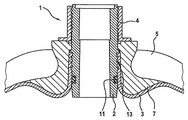
図1は、圧力タンクのタンク壁3の開口部に挿着された接続要素1を示している。接続要素1は、タンク壁3の前記開口部に挿着されている栓要素2を含んでいる。栓要素2はOリング11を介してタンク壁3に対し密封されている。
FIG. 1 shows a connecting element 1 inserted into an opening in a
タンク壁3内への栓要素2の挿着は、有利には異なる種類によって行う。一方では、栓要素2はタンク壁3の開口部に圧入可能であり、他方では栓要素2が第1のねじ山を有し、該第1のねじ山を用いて栓要素2をタンク壁3の開口部にねじ込み可能になっている。この場合、特に、タンク壁3は対向ねじ山を有しておらず、対向ねじ山は栓要素2の第1のねじ山によってタンク壁3に切り込まれる。
The insertion of the
タンク壁3と栓要素2との間の密封を改善するため、嵌め合い要素(Gegenelement)が設けられている。図1では、嵌め合い要素は金属挿入部材7である。金属挿入部材7は栓要素2のまわりに延在し、ねじ止めナット4によって固定可能である。この場合、金属挿入部材7と栓要素2とが円錐状の表面を有し、その結果ねじ止めナット4のねじ込み方向とは逆の方向に先細りになっている先細りの繰り抜き部13が金属挿入部材7の内面と栓要素2の外面との間に生じるように構成されている。従って、ねじ止めナット4のねじ込み深さが増すにつれて、タンク壁3が金属挿入部材7と栓要素2との間で締め付け固定されるように、金属挿入部材7がタンク壁3に対し押圧される。別個のねじ止めナット4を設ける代わりに、ねじ止めナット4が金属挿入部材7と一体に形成されているようにしてもよい。
In order to improve the sealing between the
結合の安定性と密封性とを向上させるため、特に、タンク壁3のまわりに繊維巻回部5も設けられている。しかしこれはオプショナルな補助手段であるにすぎない。というのは、密封性はすでに金属挿入部材7と栓要素2との間でタンク壁3を締め付け固定することによって保証されているからである。
In order to improve the stability of the connection and the sealing performance, a fiber winding part 5 is also provided, in particular around the
図2は、本発明による接続要素1の第2実施形態を示している。図1の場合と同一の要素または同種の要素には同じ参照符号が付してある。 FIG. 2 shows a second embodiment of the connection element 1 according to the invention. Elements that are the same as or similar to those in FIG. 1 are given the same reference numerals.
図1とは異なり、第2実施形態は金属円錐部6を有している。この場合、図1の金属挿入部材7に対応して、ねじ止めナット4が金属円錐部6をタンク壁3に対し押圧させ、その結果タンク壁3が金属円錐部6と栓要素2との間の繰り抜き部13内で締め付け固定されるように構成されている。このように、金属円錐部6は嵌め合い要素に相当している。金属円錐部6を固定するため、さらに金属挿入部材7が設けられており、金属円錐部6はタンク壁3と金属挿入部材7との間に設けられている。
Unlike FIG. 1, the second embodiment has a metal cone 6. In this case, corresponding to the
接続要素の第3実施形態は図3に示されている。同様に、前記実施形態の場合と同一の部材または同種の部材であれば同じ参照符号が付してある。第3実施形態では、タンク壁3を締め付け固定可能なクランプ領域12が設けられている。この場合、金属挿入部材7と栓要素2とは単に1つの領域でのみ、すなわちクランプ領域12でのみ、円錐状の表面を有し、よって先細りの繰り抜き部13を有している。従って、外壁3のクランプはクランプ領域12でのみ行われる。さらに、この第3実施形態では、ねじ止めナット4は金属挿入部材7と一体に形成されている。
A third embodiment of the connecting element is shown in FIG. Similarly, if it is the same member as the case of the said embodiment, or the same kind of member, the same referential mark is attached | subjected. In 3rd Embodiment, the clamp area | region 12 which can fasten and fix the
最後に、接続要素1の第4実施形態が図4に示されている。第4実施形態でも、上記実施形態の場合と同一の要素または同種の要素には同じ参照符号が付してある。図4で認められるように、線要素2は、先細りの繰り抜き部13を形成している円錐状の表面に加えて凹部9を有している。従ってタンク壁3は凹部9内に圧入され、これによって付加的な固定および密封が行なわれる。
Finally, a fourth embodiment of the connecting element 1 is shown in FIG. In the fourth embodiment, the same reference numerals are assigned to the same or similar elements as in the above embodiment. As can be seen in FIG. 4, the
図5は本発明による圧力タンク10を示しており、この場合圧力タンク10は特に高圧タンクである。高圧タンクは、有利には流体、ガスまたは液体を少なくとも600バールの最大圧で受容するために使用可能である。特に有利には、圧力タンク10はエンジンまたは燃料電池用の作動物質を受容するために使用可能であり、特に水素または天然ガスを受容するために使用可能である。圧力タンク10は、図4の第4実施形態による接続要素1を含んでいる。
FIG. 5 shows a
図5からわかるように、栓要素2はスリーブ形状を有している。これにより、ねじ止めナット4がねじ止めされている雄ねじ以外に、特に雌ねじも設けられており、この雌ねじにタンク弁8をねじ込み可能である。従って雌ねじは接続要素1を他の構成要素と結合させるために用いられ、よって圧力タンク10を他の構成要素と結合させるために用いられる。従って圧力タンク10は特に自動車で使用するのに適している。というのは、接続要素1は自動車の内燃エンジン用の供給管と結合可能だからである。圧力タンク10の安定性を向上させるために、タンク壁3は繊維巻回部8を備えている。
As can be seen from FIG. 5, the
図6は、図5の細部100の2つの異なる図を示している。細部100は、タンク壁3が栓要素2の凹部9になかにいかにして圧入可能であるかを示している。ねじ止めナット4によって金属挿入部材7を取り付けることにより、タンク壁3は一方では栓要素2と金属挿入部材7との楔状の表面によって締め付け固定される。さらにタンク壁3は、金属挿入部材7によって栓要素2の凹部9内へ押し込められる。従って、確実で信頼性のある結合および密封が可能である。
FIG. 6 shows two different views of
図7は本発明による圧力タンクを示しており、同様に前記実施形態の場合と同一の要素または同種の要素には同じ参照符号が付してある。図7に示した圧力タンク10の実施形態はタンク壁3を有し、該タンク壁に図3の第3実施形態による接続要素1が挿着されている。タンク壁3が繊維巻回部5を備え、その結果圧力タンク10の安定性が保証されているのが有利である。
FIG. 7 shows a pressure tank according to the present invention. Similarly, the same reference numerals are assigned to the same or similar elements as those in the above embodiment. The embodiment of the
圧力タンク10は有利には車両内で使用される。車両とは有利には自動車であり、特に乗用車である。圧力タンク10は非常に簡潔であり、コスト上好ましく製造可能であるので、圧力タンク10を車両内に設けるには非常に安いコストと非常に少ない労力とが必要であるにすぎない。
The
1 接続要素
2 栓要素
3 タンク壁
4 ねじ止めナット
5 繊維巻回部
6 金属円錐部
7 金属挿入部材
8 タンク弁
9 凹部
10 圧力タンク
11 Oリング
12 クランプ領域
13 先細り繰り抜き部
DESCRIPTION OF SYMBOLS 1
Claims (13)
栓要素(2)と、該栓要素(2)を少なくとも部分的に取り囲んでいる嵌め合い要素(6,7)と、該嵌め合い要素(6,7)と作用結合しているねじ止めナット(4)とを含み、前記栓要素(2)の外面と前記嵌め合い要素(6,7)の内面とが、前記ねじ止めナット(4)のねじ込み方向とは逆の方向に先細りになっている先細りの繰り抜き部(13)を形成し、前記ねじ止めナット(4)をねじ込むことによって前記嵌め合い要素(6,7)が前記圧力タンク(10)のタンク壁(3)に対し押圧されることで、該タンク壁(3)が前記接続要素(1)の前記繰り抜き部(13)内で締め付け固定可能である接続要素(1)。 In the connecting element (1) for the pressure tank (10), which can be inserted into the opening of the pressure tank (10),
A plug element (2), a mating element (6, 7) at least partially surrounding the plug element (2), and a screw nut (10) operatively coupled to the mating element (6, 7) 4), and the outer surface of the plug element (2) and the inner surface of the mating element (6, 7) are tapered in a direction opposite to the screwing direction of the screw nut (4). The fitting element (6, 7) is pressed against the tank wall (3) of the pressure tank (10) by forming a tapered withdrawal part (13) and screwing the screw nut (4). Thus, the connecting element (1) in which the tank wall (3) can be fastened and fixed in the drawing-out part (13) of the connecting element (1).
前記タンク壁(3)が、開口部と、請求項1から9までのいずれか一つに記載の接続要素(1)とを有し、該接続要素(1)が前記タンク壁(3)の前記開口部に挿着されている圧力タンク(10)。 In a pressure tank (10) having a tank wall (3),
The tank wall (3) is an opening, and a connecting element according to any one of claims 1 to 9 (1), said connecting element (1) is the tank wall (3) A pressure tank (10) inserted in the opening.
Applications Claiming Priority (2)
| Application Number | Priority Date | Filing Date | Title |
|---|---|---|---|
| DE102014207069.4 | 2014-04-11 | ||
| DE102014207069.4A DE102014207069A1 (en) | 2014-04-11 | 2014-04-11 | Connection element for a pressure tank and pressure tank |
Publications (2)
| Publication Number | Publication Date |
|---|---|
| JP2015203500A JP2015203500A (en) | 2015-11-16 |
| JP6464015B2 true JP6464015B2 (en) | 2019-02-06 |
Family
ID=54193207
Family Applications (1)
| Application Number | Title | Priority Date | Filing Date |
|---|---|---|---|
| JP2015081676A Active JP6464015B2 (en) | 2014-04-11 | 2015-04-13 | Connecting element for pressure tank and pressure tank |
Country Status (3)
| Country | Link |
|---|---|
| US (1) | US20150292679A1 (en) |
| JP (1) | JP6464015B2 (en) |
| DE (1) | DE102014207069A1 (en) |
Families Citing this family (16)
| Publication number | Priority date | Publication date | Assignee | Title |
|---|---|---|---|---|
| CN108139022B (en) * | 2015-11-25 | 2021-11-26 | 联合工艺公司 | Composite pressure vessel assembly with integrated nozzle assembly |
| WO2017125098A1 (en) * | 2016-01-18 | 2017-07-27 | Hpc Research S.R.O. | Boss for a composite pressure receptacle |
| WO2017125099A1 (en) * | 2016-01-18 | 2017-07-27 | Hpc Research S.R.O. | Inlet/outlet system for composite pressure receptacles |
| ITUB20160404A1 (en) * | 2016-01-26 | 2017-07-26 | Global Service Design Ltd Uk Company Number 07411425 | APPARATUS FOR THE CONTROLLED DISTRIBUTION OF A FLUID FROM A CONTAINER AND ITS RELATION METHOD |
| JP6356172B2 (en) * | 2016-03-15 | 2018-07-11 | 本田技研工業株式会社 | High pressure tank |
| KR101856334B1 (en) * | 2016-06-29 | 2018-05-09 | 현대자동차주식회사 | vessel having airtight nozzle |
| DE102016218911B4 (en) * | 2016-09-29 | 2022-04-14 | Kautex Textron Gmbh & Co. Kg | composite pressure vessel |
| ES2909886T3 (en) * | 2017-02-23 | 2022-05-10 | Nproxx B V | Pole cap with pressure connection element for pressure vessel |
| PL3575668T3 (en) * | 2018-05-29 | 2021-03-08 | Nproxx B.V. | Self-sealing valve connection for pressure vessel |
| EP3587895B1 (en) * | 2018-06-22 | 2020-10-07 | Nproxx B.V. | Self-sealing valve connection for pressure vessel |
| CN110594574A (en) * | 2019-09-29 | 2019-12-20 | 陶展鹏 | Gas steel cylinder |
| FR3102530B1 (en) * | 2019-10-24 | 2023-09-01 | Faurecia Systemes Dechappement | Pressurized gas tank |
| KR102379201B1 (en) * | 2021-06-22 | 2022-03-28 | 주식회사 신영 | High pressure gas container and manufacturing method thereof |
| DE102021130343A1 (en) | 2021-11-19 | 2023-05-25 | HC Hessentaler Container GmbH | Blow molding process with connection piece inserted |
| DE102022208132A1 (en) | 2022-08-04 | 2024-02-15 | Mahle International Gmbh | Compressed gas container |
| FR3139372A1 (en) * | 2022-09-06 | 2024-03-08 | Plastic Omnium New Energies France | Tank intended to contain gas under pressure |
Family Cites Families (16)
| Publication number | Priority date | Publication date | Assignee | Title |
|---|---|---|---|---|
| DE2152123C3 (en) | 1971-10-20 | 1974-07-11 | Elektrische Licht- Und Kraftanlagen Ag, 3579 Frielendorf | pressure vessel |
| JPS62251591A (en) * | 1986-04-23 | 1987-11-02 | 川崎製鉄株式会社 | Pipe joint |
| JPH03288091A (en) * | 1990-03-30 | 1991-12-18 | Fujitsu Ltd | Joint |
| DE19631546C1 (en) | 1996-07-24 | 1997-11-13 | Mannesmann Ag | Composite gas pressure-bottle with plastic liner |
| JPH10332084A (en) * | 1997-05-28 | 1998-12-15 | Mitsubishi Chem Corp | Pressure-resisting container |
| DE19751411C1 (en) * | 1997-11-14 | 1999-01-14 | Mannesmann Ag | Composite fibre-reinforced pressurised gas tank including liner with end neck sections |
| JP2002537530A (en) * | 1999-02-16 | 2002-11-05 | アライアント・テクシステムズ・インコーポレーテッド | Compressed gas storage assembly |
| DE10000705A1 (en) * | 2000-01-10 | 2001-07-19 | Ralph Funck | Pressure container for storing liquid and / or gaseous media under pressure consisting of a plastic core container which is reinforced with fiber-reinforced plastics and process for its production |
| US7837054B2 (en) | 2004-09-23 | 2010-11-23 | Quantum Fuel Systems Technologies Worldwide, Inc. | Tank seal |
| NO326109B1 (en) * | 2007-06-14 | 2008-09-22 | Compressed Energy Tech As | Endeboss and a composite pressure tank |
| DE102009014057A1 (en) | 2009-03-20 | 2010-09-23 | Daimler Ag | Pressure vessel for storing hydrogen gas for driving land-based motor vehicle, has liner made of plastic, and flange cooperating with support ring at wall, where section of outer circumference of flange is conical |
| DE102009049948B4 (en) | 2009-10-19 | 2012-02-02 | Kautex Maschinenbau Gmbh | pressure vessel |
| US8186536B2 (en) | 2009-11-04 | 2012-05-29 | GM Global Technology Operations LLC | Molding process of liner with divided boss adapter |
| DE102010018700B4 (en) * | 2010-04-29 | 2019-05-09 | Magna Steyr Fahrzeugtechnik Ag & Co. Kg | pressure vessel |
| DE102010023386A1 (en) | 2010-06-10 | 2011-12-15 | Volkswagen Ag | Pressure tank for storing liquids or gaseous mediums, particularly for installing in vehicle, has base body made of plastic forming storage compartment for liquid and gaseous medium |
| JP6153475B2 (en) * | 2014-01-10 | 2017-06-28 | 株式会社Fts | Pressure vessel base structure |
-
2014
- 2014-04-11 DE DE102014207069.4A patent/DE102014207069A1/en active Pending
-
2015
- 2015-04-13 US US14/684,890 patent/US20150292679A1/en not_active Abandoned
- 2015-04-13 JP JP2015081676A patent/JP6464015B2/en active Active
Also Published As
| Publication number | Publication date |
|---|---|
| US20150292679A1 (en) | 2015-10-15 |
| DE102014207069A1 (en) | 2015-10-15 |
| JP2015203500A (en) | 2015-11-16 |
Similar Documents
| Publication | Publication Date | Title |
|---|---|---|
| JP6464015B2 (en) | Connecting element for pressure tank and pressure tank | |
| US8640910B2 (en) | Pressure container | |
| JP7027439B2 (en) | Pole cap with pressure port element for pressure vessel | |
| ES2757594T3 (en) | Valve component | |
| WO2010058452A1 (en) | High-pressure tank | |
| KR20120086294A (en) | Vessel neck construction of a pressure vessel | |
| KR20110027820A (en) | Motor vehicle fuel tank | |
| CN108139012B (en) | Threaded plug | |
| US10954906B2 (en) | Fuel injector having an improved high-pressure connection | |
| RU2009105122A (en) | RESERVOIR FOR TRANSPORTATION AND STORAGE OF LIQUIDS | |
| ES2344136T3 (en) | UNION DEVICE FOR CONNECTING A PRESSURE CONTAINER WITH A LIQUID GAS FILLING MOUTH. | |
| JP2005510665A (en) | Support sleeve for use in a pipe joint and joint housing for use with said sleeve | |
| WO2016010079A1 (en) | Terminal seal structure for direct-injection gasoline engine fuel rail | |
| WO2016021687A1 (en) | End-sealing structure for fuel rail for gasoline direct injection engine | |
| US9784390B2 (en) | Screw connection device for connecting the flared ends of two pipes | |
| JP2008526634A (en) | Mounting parts for forming fluid inductive connections | |
| JP7190041B2 (en) | High-pressure tank sealing device and high-pressure tank containing the same | |
| JP2008014342A (en) | Tank | |
| RU2667197C2 (en) | Fuel distributor guide end seal design for the direct injection gasoline engine | |
| KR101568793B1 (en) | Connecting Srtucture Of Pipes | |
| US8602460B2 (en) | Adapter for connecting fluid source to water bed | |
| CN110088524B (en) | Valve block and accumulator device provided with same | |
| US11320080B2 (en) | Connection device | |
| KR200488599Y1 (en) | packing for connecting pipe and connecting pipe having the same | |
| CN104675593A (en) | High-pressure oil pipe |
Legal Events
| Date | Code | Title | Description |
|---|---|---|---|
| A621 | Written request for application examination |
Free format text: JAPANESE INTERMEDIATE CODE: A621 Effective date: 20171108 |
|
| A977 | Report on retrieval |
Free format text: JAPANESE INTERMEDIATE CODE: A971007 Effective date: 20180920 |
|
| A131 | Notification of reasons for refusal |
Free format text: JAPANESE INTERMEDIATE CODE: A131 Effective date: 20181002 |
|
| A521 | Request for written amendment filed |
Free format text: JAPANESE INTERMEDIATE CODE: A523 Effective date: 20181127 |
|
| TRDD | Decision of grant or rejection written | ||
| A01 | Written decision to grant a patent or to grant a registration (utility model) |
Free format text: JAPANESE INTERMEDIATE CODE: A01 Effective date: 20181211 |
|
| A61 | First payment of annual fees (during grant procedure) |
Free format text: JAPANESE INTERMEDIATE CODE: A61 Effective date: 20190107 |
|
| R150 | Certificate of patent or registration of utility model |
Ref document number: 6464015 Country of ref document: JP Free format text: JAPANESE INTERMEDIATE CODE: R150 |
|
| R250 | Receipt of annual fees |
Free format text: JAPANESE INTERMEDIATE CODE: R250 |
|
| R250 | Receipt of annual fees |
Free format text: JAPANESE INTERMEDIATE CODE: R250 |
|
| R250 | Receipt of annual fees |
Free format text: JAPANESE INTERMEDIATE CODE: R250 |