JP6463753B2 - Fluid applicator comprising a modular nozzle assembly for applying fluid to an article - Google Patents
Fluid applicator comprising a modular nozzle assembly for applying fluid to an article Download PDFInfo
- Publication number
- JP6463753B2 JP6463753B2 JP2016531063A JP2016531063A JP6463753B2 JP 6463753 B2 JP6463753 B2 JP 6463753B2 JP 2016531063 A JP2016531063 A JP 2016531063A JP 2016531063 A JP2016531063 A JP 2016531063A JP 6463753 B2 JP6463753 B2 JP 6463753B2
- Authority
- JP
- Japan
- Prior art keywords
- fluid
- modular
- nozzle assembly
- orifice
- strand
- Prior art date
- Legal status (The legal status is an assumption and is not a legal conclusion. Google has not performed a legal analysis and makes no representation as to the accuracy of the status listed.)
- Active
Links
- 239000012530 fluid Substances 0.000 title claims description 195
- 239000000463 material Substances 0.000 claims description 19
- 230000000712 assembly Effects 0.000 claims description 12
- 238000000429 assembly Methods 0.000 claims description 12
- 239000011248 coating agent Substances 0.000 claims description 10
- 238000000576 coating method Methods 0.000 claims description 10
- 230000014759 maintenance of location Effects 0.000 claims description 2
- 230000007246 mechanism Effects 0.000 claims description 2
- 239000000853 adhesive Substances 0.000 description 18
- 230000001070 adhesive effect Effects 0.000 description 18
- 239000003292 glue Substances 0.000 description 14
- 239000000835 fiber Substances 0.000 description 10
- 238000004891 communication Methods 0.000 description 8
- 238000000034 method Methods 0.000 description 6
- 230000008569 process Effects 0.000 description 4
- 239000000758 substrate Substances 0.000 description 4
- 239000011324 bead Substances 0.000 description 3
- 230000008859 change Effects 0.000 description 3
- 238000012986 modification Methods 0.000 description 3
- 230000004048 modification Effects 0.000 description 3
- 239000004745 nonwoven fabric Substances 0.000 description 3
- 206010021639 Incontinence Diseases 0.000 description 2
- 230000009286 beneficial effect Effects 0.000 description 2
- RNFJDJUURJAICM-UHFFFAOYSA-N 2,2,4,4,6,6-hexaphenoxy-1,3,5-triaza-2$l^{5},4$l^{5},6$l^{5}-triphosphacyclohexa-1,3,5-triene Chemical compound N=1P(OC=2C=CC=CC=2)(OC=2C=CC=CC=2)=NP(OC=2C=CC=CC=2)(OC=2C=CC=CC=2)=NP=1(OC=1C=CC=CC=1)OC1=CC=CC=C1 RNFJDJUURJAICM-UHFFFAOYSA-N 0.000 description 1
- 239000004831 Hot glue Substances 0.000 description 1
- 229920002334 Spandex Polymers 0.000 description 1
- 230000001580 bacterial effect Effects 0.000 description 1
- 230000004888 barrier function Effects 0.000 description 1
- 238000004140 cleaning Methods 0.000 description 1
- 239000000470 constituent Substances 0.000 description 1
- 230000003467 diminishing effect Effects 0.000 description 1
- 239000013013 elastic material Substances 0.000 description 1
- 239000004744 fabric Substances 0.000 description 1
- 239000003063 flame retardant Substances 0.000 description 1
- 230000036512 infertility Effects 0.000 description 1
- 230000001788 irregular Effects 0.000 description 1
- 238000012423 maintenance Methods 0.000 description 1
- 238000004519 manufacturing process Methods 0.000 description 1
- 230000005855 radiation Effects 0.000 description 1
- 230000004044 response Effects 0.000 description 1
- 239000004759 spandex Substances 0.000 description 1
- XLYOFNOQVPJJNP-UHFFFAOYSA-N water Substances O XLYOFNOQVPJJNP-UHFFFAOYSA-N 0.000 description 1
- 238000003466 welding Methods 0.000 description 1
Images


Classifications
-
- B—PERFORMING OPERATIONS; TRANSPORTING
- B05—SPRAYING OR ATOMISING IN GENERAL; APPLYING FLUENT MATERIALS TO SURFACES, IN GENERAL
- B05C—APPARATUS FOR APPLYING FLUENT MATERIALS TO SURFACES, IN GENERAL
- B05C5/00—Apparatus in which liquid or other fluent material is projected, poured or allowed to flow on to the surface of the work
- B05C5/02—Apparatus in which liquid or other fluent material is projected, poured or allowed to flow on to the surface of the work the liquid or other fluent material being discharged through an outlet orifice by pressure, e.g. from an outlet device in contact or almost in contact, with the work
- B05C5/0245—Apparatus in which liquid or other fluent material is projected, poured or allowed to flow on to the surface of the work the liquid or other fluent material being discharged through an outlet orifice by pressure, e.g. from an outlet device in contact or almost in contact, with the work for applying liquid or other fluent material to a moving work of indefinite length, e.g. to a moving web
-
- B—PERFORMING OPERATIONS; TRANSPORTING
- B05—SPRAYING OR ATOMISING IN GENERAL; APPLYING FLUENT MATERIALS TO SURFACES, IN GENERAL
- B05C—APPARATUS FOR APPLYING FLUENT MATERIALS TO SURFACES, IN GENERAL
- B05C5/00—Apparatus in which liquid or other fluent material is projected, poured or allowed to flow on to the surface of the work
- B05C5/02—Apparatus in which liquid or other fluent material is projected, poured or allowed to flow on to the surface of the work the liquid or other fluent material being discharged through an outlet orifice by pressure, e.g. from an outlet device in contact or almost in contact, with the work
- B05C5/0241—Apparatus in which liquid or other fluent material is projected, poured or allowed to flow on to the surface of the work the liquid or other fluent material being discharged through an outlet orifice by pressure, e.g. from an outlet device in contact or almost in contact, with the work for applying liquid or other fluent material to elongated work, e.g. wires, cables, tubes
-
- B—PERFORMING OPERATIONS; TRANSPORTING
- B05—SPRAYING OR ATOMISING IN GENERAL; APPLYING FLUENT MATERIALS TO SURFACES, IN GENERAL
- B05C—APPARATUS FOR APPLYING FLUENT MATERIALS TO SURFACES, IN GENERAL
- B05C5/00—Apparatus in which liquid or other fluent material is projected, poured or allowed to flow on to the surface of the work
- B05C5/02—Apparatus in which liquid or other fluent material is projected, poured or allowed to flow on to the surface of the work the liquid or other fluent material being discharged through an outlet orifice by pressure, e.g. from an outlet device in contact or almost in contact, with the work
- B05C5/027—Coating heads with several outlets, e.g. aligned transversally to the moving direction of a web to be coated
Description
以下の記載は、物品に流体を塗布するモジュラーノズルを備える流体塗布装置、特に、流体塗布装置に対して選択的に着脱することができ、流体塗布装置上のモジュラーノズルアセンブリを交換可能にするモジュラーノズルアセンブリを備える流体塗布装置に関する。 The following description is directed to a fluid application device comprising a modular nozzle for applying fluid to an article, and more particularly to a modular device that can be selectively attached to and detached from the fluid application device and replaces the modular nozzle assembly on the fluid application device. The present invention relates to a fluid application apparatus including a nozzle assembly.
不織布は、吸収性、撥水性、弾性、伸縮性、柔軟性、強度、難燃性保護、クリーニング簡易性、クッション性、濾過性、細菌バリアとしての用途、及び無菌性等の特有の機能性を提供する工業用の布である。不織布は、他の材料と組み合わせて、多様な特性を有する様々な製品を提供することができ、また、単独で又は衛生衣類、家庭用品、ヘルスケア用品、工業用品、産業用品、及び消費者用品の構成部材として使用することができる。 Non-woven fabric has unique functionality such as absorbency, water repellency, elasticity, stretchability, flexibility, strength, flame retardant protection, easy cleaning, cushioning, filterability, bacterial barrier, and sterility. It is an industrial cloth to be provided. Nonwovens can be combined with other materials to provide a variety of products with a variety of properties, and alone or in sanitary garments, household goods, healthcare products, industrial products, industrial products, and consumer products. It can be used as a constituent member.
複数の伸縮性ストランドを不織材料上に配置及び接合し、例えば物体又は人体の周囲に柔軟にフィットすることを可能にすることができる。ストランドは、糊又は糊ファイバー等の接着剤を用いて不織布に接着することができる。1つの形態において、ストランドは、接着剤塗布装置にあるノズルを通過して給送される。ノズルは、糊又は糊ファイバーを吐出することができる複数の穴を有することができる。いくつかのノズルでは、糊ファイバーの塗布を制御するように、別個の出口を通して空気等の第2の流体を吐出することができ、それにより、ストランドがノズルを通過する際、糊ファイバーはそれぞれのストランドを横切るように揺れ動かされる。 A plurality of stretchable strands can be placed and joined on the nonwoven material to allow for a flexible fit around an object or human body, for example. The strand can be bonded to the nonwoven fabric using an adhesive such as glue or glue fiber. In one form, the strands are fed through a nozzle in an adhesive applicator. The nozzle can have a plurality of holes through which glue or glue fibers can be discharged. In some nozzles, a second fluid, such as air, can be ejected through a separate outlet to control the application of the glue fiber, so that as the strand passes through the nozzle, the glue fiber It is swung across the strand.
接着剤塗布装置は、接触ノズル又は非接触ノズルのいずれかを用いてストランドに接着剤を塗布することができる。接触ノズルは、材料ストランド等の基材が糊の近傍に給送される際、材料ストランド上に略変動しない或る体積の糊を吐出する。ストランドは、給送される際に糊と接触し、糊は、接触の結果としてストランドに付着する。非接触ノズルでは、糊は、例えばファイバーとして出口から吐出することができる。糊は、出口とストランドとの間の間隙を越えるように吐出され、最終的にストランド上に受け取られる。糊ファイバーの吐出は、ストランド上に塗布する間、糊ファイバーを揺れ動かすように、隣接する出口から吐出される空気等の第2の流体によって制御することができる。 The adhesive applicator can apply the adhesive to the strand using either a contact nozzle or a non-contact nozzle. The contact nozzle discharges a certain volume of glue that does not vary substantially on the material strand when a substrate such as a material strand is fed in the vicinity of the glue. The strand contacts the glue as it is fed, and the glue adheres to the strand as a result of the contact. In the non-contact nozzle, the glue can be discharged from the outlet as, for example, a fiber. The glue is ejected across the gap between the outlet and the strand and finally received on the strand. The discharge of the glue fiber can be controlled by a second fluid such as air discharged from an adjacent outlet so as to sway the glue fiber during application on the strand.
個々の用途に応じて異なるタイプのノズル、すなわち接触ノズル又は非接触ノズルが望ましい場合がある。しかしながら現在では、異なるノズルを提供するためには、異なる接着剤塗布装置が使用される。すなわち、非接触用途に使用される非接触ノズルを装備する接着剤塗布装置は、接触用途に使用される接触ノズルを装備するように容易に変更することができず、その逆も同様である。したがって現在では、接触ノズル及び非接触ノズルに関連する異なるストランドコーティング特性を提供するために、複数の接着剤塗布装置が使用される。そのため、機器の追加によって多大な費用が発生する場合がある。 Depending on the particular application, different types of nozzles may be desirable: contact nozzles or non-contact nozzles. Currently, however, different adhesive applicators are used to provide different nozzles. That is, an adhesive applicator equipped with a non-contact nozzle used for non-contact applications cannot be easily modified to be equipped with a contact nozzle used for contact applications, and vice versa. Thus, multiple adhesive applicators are currently used to provide different strand coating properties associated with contact nozzles and non-contact nozzles. For this reason, there is a case where a great expense is generated by adding the device.
したがって、単一の流体塗布装置を用いて異なる塗布特性を提供するように、容易かつ選択的に取り外して、同じ又は異なるタイプのノズルアセンブリと交換することができるモジュラーノズルアセンブリを備える流体塗布装置を提供することが望ましい。 Accordingly, a fluid application device comprising a modular nozzle assembly that can be easily and selectively removed and replaced with the same or different type of nozzle assembly to provide different application characteristics using a single fluid application device. It is desirable to provide.
1つの実施形態によれば、塗布ヘッドと、塗布ヘッドに流体的に結合されるモジュラーノズルアセンブリとを備える流体塗布装置が提供される。モジュラーノズルアセンブリは、材料ストランドを受けるように構成されている少なくとも1つのガイドスロットと、それぞれの材料ストランド上に第1の流体を吐出するように構成されている少なくとも1つのオリフィスと、モジュラーノズルアセンブリを貫通する少なくとも1つの固定穴を有する。各固定穴は、固定要素を受けるように構成されている。モジュラーノズルアセンブリは、固定要素を各固定穴によって受けることにより、本流体塗布装置に取外し可能に取り付けられる。モジュラーノズルアセンブリは、モジュラー式接触ノズルアセンブリ及びモジュラー式非接触ノズルアセンブリのうちの一方であり、モジュラー式接触ノズルアセンブリ及びモジュラー式非接触ノズルアセンブリのうちの一方は、他方と交換可能に塗布ヘッドに取付け可能である。例えば、モジュラーノズルアセンブリは、非接触ノズル、ストランド上への第1の流体の流れ及び塗布の変動を引き起こす流体アシスト又は空気アシストを伴う接触ノズル、及び流体アシスト又は空気アシストを伴わない接触ノズルとすることができる。異なるモジュラーノズルアセンブリを本流体塗布装置とともに交換可能に使用することができる。したがって、本流体塗布装置は、非接触ノズルを備える非接触タイプの本流体塗布装置と、ストランドへの塗布中に第1の流体の流れを変更又は変動させるように流体アシスト又は空気アシストを伴う接触ノズルを備える接触タイプの流体塗布装置と、流体アシスト又は空気アシストを伴わない接触ノズル備える接触タイプの流体塗布装置との間で変更することができる。 According to one embodiment, a fluid application apparatus is provided that includes an application head and a modular nozzle assembly that is fluidly coupled to the application head. The modular nozzle assembly includes at least one guide slot configured to receive material strands, at least one orifice configured to eject a first fluid on each material strand, and a modular nozzle assembly. At least one fixing hole. Each fixing hole is configured to receive a fixing element. The modular nozzle assembly is removably attached to the fluid application device by receiving a securing element through each securing hole. The modular nozzle assembly is one of a modular contact nozzle assembly and a modular non-contact nozzle assembly, one of the modular contact nozzle assembly and the modular non-contact nozzle assembly being interchangeable with the other to the application head. It can be installed. For example, the modular nozzle assembly may be a non-contact nozzle, a contact nozzle with fluid assist or air assist that causes variations in the first fluid flow and application onto the strand, and a contact nozzle without fluid assist or air assist. be able to. Different modular nozzle assemblies can be used interchangeably with the fluid application apparatus. Accordingly, the fluid application device includes a non-contact type fluid application device having a non-contact nozzle and contact with fluid assist or air assist so as to change or change the flow of the first fluid during application to the strand. It can be changed between a contact-type fluid application device comprising a nozzle and a contact-type fluid application device comprising a contact nozzle without fluid assist or air assist.
別の実施形態によれば、流体塗布装置用のモジュラーノズルアセンブリが提供される。本モジュラーノズルアセンブリは、材料ストランドを受けるように構成されている少なくとも1つのガイドスロットと、それぞれの材料ストランド上に第1の流体を吐出するように構成されている少なくとも1つのオリフィスと、本モジュラーノズルアセンブリを貫通する少なくとも1つの固定穴とを有する。各固定穴は、固定要素を受けるように構成されている。 According to another embodiment, a modular nozzle assembly for a fluid application device is provided. The modular nozzle assembly includes at least one guide slot configured to receive material strands, at least one orifice configured to eject a first fluid onto each material strand, and the modular nozzle assembly. And at least one fixing hole extending through the nozzle assembly. Each fixing hole is configured to receive a fixing element.
本開示の他の目的、特徴、及び利点は、添付の図面と併せて以下の記載から明らかとなるであろう。添付の図面において、同様の参照符号は同様の部分、部材、部品、ステップ、及びプロセスを指す。 Other objects, features and advantages of the present disclosure will become apparent from the following description taken in conjunction with the accompanying drawings. In the accompanying drawings, like reference numbers indicate like parts, members, parts, steps, and processes.
本開示は種々の形態の実施形態が可能であるが、1つ又は複数の実施形態が図面に示されるとともに以下で記載される。本開示は単なる例示とみなされ、また、本開示を記載又は図示されているいかなる特定の実施形態に限定することも意図していないことが理解される。 While the present disclosure is capable of various forms of embodiment, one or more embodiments are shown in the drawings and are described below. It is understood that this disclosure is considered merely illustrative and is not intended to limit the disclosure to any particular embodiment described or illustrated.
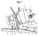
図1は、本明細書に記載の一実施形態に係る流体塗布装置10の斜視図である。流体塗布装置10は、流体を吐出するモジュラーノズルアセンブリを使用して、装置10の近傍に給送される物品上に流体を塗布するように用いることができる。モジュラーノズルアセンブリは、以下で更に記載する振動能力を有するか若しくは有しない、モジュラー式非接触ノズルアセンブリ又はモジュラー式接触ノズルアセンブリとすることができる。流体塗布装置10は、物品上に第1の流体を塗布することができる。第1の流体は、加熱されたか又は非加熱の液化材料である、10センチポアズ(cps)〜50000センチポアズ(cps)の粘性流体とすることができる。第1の流体は、例えば接着剤とすることができ、物品は、例えば材料ストランド12とすることができる。すなわち、1つの実施形態において、流体塗布装置10は、ストランドコーティングシステムの一部である。ストランド12を不織材料等の基材14に接着させるように、ストランド12に接着剤を塗布することができる。ストランド12は、弾性又は非弾性の材料製とすることができ、第1の流体が塗布される際、伸張状態であっても弛緩状態であってもよい。材料ストランド12は、例えば、スパンデックス、ゴム、又は他の同様の弾性材料とすることができる。
FIG. 1 is a perspective view of a
1つの実施形態によれば、流体塗布装置10は塗布ヘッド16を備える。塗布ヘッド16は、第1の流体供給ユニット18と、第2の流体供給ユニット20と、モジュラーノズルアセンブリ22とを備えることができる。モジュラーノズルアセンブリ22は、例えばモジュラー式非接触ノズルアセンブリ22とすることができる。第1の流体供給ユニット18は、第1の流体源(図示せず)から第1の流体を受け取るように構成され、第2の流体供給ユニット20は、第2の流体源(図示せず)から第2の流体を受け取るように構成されている。モジュラーノズルアセンブリ22は、第1の流体供給ユニット18に流体的に結合される、すなわち第1の流体供給ユニット18と流体連通する。モジュラーノズルアセンブリ22は、同様に、第2の流体供給ユニット20に流体的に結合することができる、すなわち第2の流体供給ユニット20と流体連通することができる。したがって、モジュラーノズルアセンブリ22は、第1の流体供給ユニット18から第1の流体を受け取り、第2の流体供給ユニット20から第2の流体を受け取ることができる。
According to one embodiment, the
また、いくつかの実施形態において、塗布ヘッド16は、第1の流体供給ユニット18及び第2の流体供給ユニット20のうちの少なくとも一方に固定されるアダプター24を備えることができる。アダプター24は、モジュラーノズルアセンブリ22に隣接して配置され、モジュラーノズルアセンブリ22に流体的に結合される、すなわちモジュラーノズルアセンブリ22と流体連通する。さらに、アダプター24は、モジュラーノズルアセンブリ22がアダプター24を介して第1の流体及び第2の流体を受け取ることができるように、第1の流体供給ユニット18及び第2の流体供給ユニット20のうちの一方又は双方に流体的に結合される。すなわち、アダプター24は、第1の流体供給ユニット18及び第2の流体供給ユニット20のうちの一方又は双方及びまたモジュラーノズルアセンブリ22と流体連通する。アダプター24は、ストランド12上への第1の流体の塗布に向けて、モジュラーノズルアセンブリ22がストランド12及び塗布ヘッド16に対して適切に位置決めされるとともにストランド12及び塗布ヘッド16に向けられ得るように、モジュラーノズルアセンブリ22がアダプター24に固定されるよう構成されている。
In some embodiments, the application head 16 can include an
また、塗布ヘッド16は、流れ制御モジュール26を備えることができる。流れ制御モジュール26は弁又は1連の弁を備え、第1の流体供給ユニット18からモジュラーノズルアセンブリ22への第1の流体の流れ及び第2の流体供給ユニット20からモジュラーノズルアセンブリ22への第2の流体の流れをそれぞれ調節することができる。いくつかの実施形態において、アダプター24と流れ制御モジュール26とは同じユニットとして実施される。このユニットは、第1の流体供給ユニット18及び第2の流体供給ユニット20のうちの一方又は双方とノズルアセンブリ22との間の接着剤路を提供する。このユニット、すなわち組み合わされたアダプター24及び流れ制御モジュール26は、接着剤の流れを開始及び停止する弁を備えることもできる。
The application head 16 can also include a flow control module 26. The flow control module 26 comprises a valve or a series of valves, and a first fluid flow from the first
図1を更に参照すると、モジュラーノズルアセンブリ22は、塗布ヘッド16、アダプター24、又は塗布ヘッド16の他の隣接する構成部材に固定することができる。上述したように、モジュラーノズルアセンブリ22は、モジュラー式非接触ノズルアセンブリ22として形成することができる。モジュラー式非接触ノズルアセンブリ22では、第1の流体を、オリフィス28から間隙を越えるように吐出し、ストランド12上に受け取る。すなわち、非接触ノズル用途では、流体塗布プロセス中、ノズルはストランド12から離間する。
With further reference to FIG. 1, the
モジュラーノズルアセンブリ22は、少なくとも1つのオリフィス28を有する。各材料ストランド12と関連付けられる少なくとも1つのオリフィス28が存在することができる。すなわち、各オリフィス28は、それぞれのストランド12上に第1の流体を吐出することができる。各オリフィス28は、幅が約0.41mm(0.016in)〜0.51mm(0.020in)とすることができるが、これに限定されない。例えば、オリフィス28の幅は、様々な寸法のストランド12に適応するように変更してもよい。さらに、非接触ノズルでは、第2の流体を、モジュラーノズルアセンブリ22のそれぞれのオリフィス28に隣接する少なくとも1つの出口から吐出することができる。第2の流体を用いて、ストランド12上への塗布中に第1の流体の吐出経路を変更するように、第1の流体の塗布を制御するか又は別様に第1の流体に作用することができる。例えば、第2の流体は、第1の流体の塗布時に第1の流体を振動させることができる。したがって、第1の流体は、ストランド12上に所望のパターンで塗布することができる。
The
第1の流体は、ホットメルト接着剤等の接着剤とすることができる。接着剤は、オリフィス28からフィラメント又はファイバーとして吐出し、ストランド12上に塗布することができる。第1の流体は、オリフィス28から実質的に連続したフィラメント又はファイバーとして吐出してもよいが、第1の流体がストランド12に十分に塗布され、ストランド12が基材14に満足に接着することが可能になる限り、間欠的に不連続としてもよい。いくつかの実施形態において、第2の流体は、第1の流体をストランド12上に不連続的に塗布させる。塗布ヘッド16は、第1の流体を溶融するか又は第1の流体を溶融状態に維持するように加熱することができる。例えば、第1の流体供給ユニット18、第2の流体供給ユニット20、及び/又はモジュラーノズルアセンブリ22を加熱することができ、ひいては熱を外側に放射することもできる。塗布ヘッド16はヒーターを備えることもできる。
The first fluid can be an adhesive such as a hot melt adhesive. The adhesive can be discharged as a filament or fiber from the
第2の流体は、例えば空気とすることができ、上述したように、第2の流体を用いて、モジュラーノズルアセンブリ22のオリフィス28からストランド12上への第1の流体の吐出を制御するか又は別様に影響を与えることができる。1つの実施形態において、第1の流体を吐出する各オリフィス28に隣接して第2の流体を吐出するように構成されている少なくとも2つの出口が存在する。しかし、各オリフィス28と関連付けられる出口の数は変更してもよいことが理解される。例えば、1つ〜6つの出口を各オリフィス28に関連付けることができる。第2の流体は、各オリフィス28に隣接する出口から交互に吐出し、第1の流体を振動させるとともにストランド12に所望のパターンで塗布させることができる。1つの実施形態において、第1の流体は、ストランド12に略正弦波状パターンで塗布することができる。しかし、本開示はこの塗布パターンに限定されない。例えば、第1の流体は、第1の流体が例えば、単数又は複数の繰返しパターン、非繰返しパターン、不規則パターン、及び/又は非対称パターンで塗布されるように、第2の流体によって揺れ動かすか又は振動させることができる。
The second fluid can be, for example, air, and as described above, can the second fluid be used to control the discharge of the first fluid from the
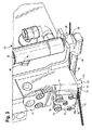
図2は流体塗布装置10の斜視図である。図1及び図2を参照すると、流体塗布装置10はストランド係合装置30を更に備える。ストランド係合装置30は、塗布ヘッド16と一体に形成するか、又は塗布ヘッド16に動作可能に接続することができる。代替的には、ストランド係合装置30は、限定はしないが、ボルト、ねじ、リベットを含む好適な締結具、接着剤、溶接等によって、塗布ヘッド16に又は流体塗布装置10の他の構成部材に固定することができる。ストランド係合装置30は、以下で更に論じるように流体塗布装置10のライン状態(稼動状態又は静止状態)に基づき、ストランド12に係合してストランド12を塗布ヘッド16及びモジュラーノズルアセンブリ22に対して接離させるように構成されている。
FIG. 2 is a perspective view of the
依然として図1及び図2を参照すると、モジュラー式非接触ノズルアセンブリ22はガイドプレート32を備え、モジュラーノズルアセンブリ22のオリフィス28及び出口に対するストランド12の位置決めを援助することができる。ガイドプレート32は少なくとも1つのガイドスロット34を有し、少なくとも1つのガイドスロット34を通してストランド12を給送することができる。ガイドスロット34は略逆V字形に形成することができ、ガイドスロット34の開放端部36が逆V字形の幅広部に相当し、ガイドスロットの閉鎖端部38が逆V字形の狭小部に相当する。閉鎖端部38は、第1の流体の塗布に向けて、ストランド12をオリフィス28及び出口に対する所望の位置に位置決めするように、ストランド12の制限部すなわち停止部として機能することができる。すなわち、閉鎖端部38は、ストランド12を、オリフィス28から所定の距離を置いて位置決めするように停止部として機能することができる。ストランド12は、閉鎖端部38に接触してもよいし、閉鎖端部38に近接して配置してもよい。ストランド12とオリフィス28との間の所定の距離は、オーバースプレーを低減又は最小限にすることができる距離又は間隙である。ストランド12の進行方向において、少なくとも1つのガイドスロット34は、モジュラーノズルアセンブリ22のオリフィス28の手前に配置することができる。
Still referring to FIGS. 1 and 2, the modular
1つの実施形態によれば、少なくとも1つのガイドスロット34は、3つのガイドスロット34を含むことができる。しかしながら、ガイドスロット34の数は変更してもよく、上記例には限定されないことが理解される。各ガイドスロット34は、モジュラーノズルアセンブリ22の対応するオリフィス28と関連付けられる。すなわち、各ガイドスロット34は、モジュラーノズルアセンブリ22の対応するオリフィス28と略整列することができる。例えば、それぞれのガイドスロット34の閉鎖端部38は、ストランド12の進行方向においてそれぞれのオリフィス28と整列することができる。各ガイドスロット34は、1つの別個のストランド12を受けるように構成されているが、2つ以上のストランド12を各ガイドスロット34に受けてもよいことが想定される。
According to one embodiment, the at least one
1つの実施形態において、モジュラーノズルアセンブリ22は、本体部22aを備え、ガイドプレート32は、本体部22aとは別個に形成される。ガイドプレート32は、アダプター24に固定される第1のフランジ40と、第1のフランジ40から垂下する第2のフランジ42とによって形成することができる。少なくとも1つのガイドスロット34は、第2のフランジ42に形成することができる。ガイドプレート32は、ストランド12に干渉しない既知の取外し可能な締結技術を用いてアダプター24に固定することができる。例えば、ガイドプレート32は、ボルト、ねじ、若しくは他のねじ付き締結具、剥離可能な接着剤、蟻継ぎ嵌合、スナップ嵌め若しくは摩擦嵌め、及び同様の好適な締結技術、又はこれらの組合せを用いて、アダプター24又は塗布ヘッド16の他の隣接する部分に固定することができる。アダプター24又は塗布ヘッド16の他の隣接する構成部材は、ガイドプレート32が取外し可能に固定され得るように、対応するか又は合致する締結具構成部材を備えることができる。したがって、ガイドプレート32は、モジュラーノズルアセンブリ22とは独立して保守点検又は交換のために取り外すことができる。代替的には、ガイドプレート32は、モジュラーノズルアセンブリ22の本体部22aと一体に形成することができる。例えば、ガイドプレート32は、ガイドスロット34が形成される本体部22aから垂下するフランジを有することができる。
In one embodiment, the
図2を更に参照すると、ストランド係合装置30は、単数又は複数のストランド12を支持及び/又はガイドするように構成されている係合アーム44を備える。係合アーム44は、それぞれのガイドスロット34に及び/又はガイドスロット34内でストランド12を移動させ、ストランド12をそれぞれのオリフィス28及び出口に対して正確に位置決めするように調整可能であり、それにより、ストランド12がそれぞれのオリフィス28と整列され、オリフィス28から所望の距離すなわち所望の間隙を置いて保持される。
With further reference to FIG. 2, the
図2は、第1の位置にある係合アーム44を示している。図3は、係合アーム44が第2の位置にある流体塗布装置10の斜視図である。すなわち、係合アーム44は、図2に示す第1の位置と、図3に示す第2の位置との間で調整可能である。第1の位置は、係合アーム44が塗布ヘッド16から第1の距離だけ離間する位置に相当する。第1の距離は、塗布ヘッド16及び/又はモジュラーノズルアセンブリ22からの熱放射によって発生する、溶落ち等のストランド12の損傷を防止又は抑制するのに十分なものである。例えば、係合アーム44は、第1の位置では、ストランド12をオリフィス28及び/又は塗布ヘッド16の熱源から約3mm〜5mmを置いて保持することができる。係合アーム44を第1の位置に移動して、係合アーム44を第1の位置に維持することは、流体塗布装置10が、ストランド12がモジュラーノズルアセンブリ22を通過して給送されないライン静止状態にある場合に有益とすることができる。
FIG. 2 shows the
第2の位置は、係合アーム44が塗布ヘッド16又はオリフィス28から第1の距離よりも短い第2の距離だけ離間し、それによりストランド12が塗布ヘッド16及びそれぞれのオリフィス28に対してより近位に移動された位置に相当する。1つの例において、係合アーム44の第2の位置は、ストランドをモジュラーノズルアセンブリ22のオリフィス28から約1mm〜3mm、より好ましくは1mm〜2mmを置いて位置決めする。すなわち、係合アーム44の第2の位置は、第1の流体がストランド12上に塗布される際に越える間隙に略相当する。係合アーム44を第2の位置に移動して、係合アームを第2の位置に維持することは、流体塗布装置10がライン稼動状態である場合に有益とすることができ、それにより、第1の流体をストランド12上に効率的に塗布することができる。例えば、ストランド12上への第1の流体のオーバースプレーは、係合アーム44が第2の位置にある場合、第1の位置に比較して低減することができる。
The second position is such that the
依然として図2及び図3を参照すると、係合アーム44は、作動アセンブリ48によって調整することができる。作動アセンブリ48は、例えば、空気によって制御されるピストン50及びシリンダー52とすることができる。例えば、ピストン50は、シリンダー52内で、シリンダー52に導入される空気又は別の気体に応じて可動とすることができる。ピストン50は、シリンダー52を出入りするピストン50の動きによって、係合アーム44が塗布ヘッド16に対して接離するように、係合アーム44に直接的に又は間接的に接続することができる。上記実施形態は、空気によって制御されるピストン及びシリンダーを備える作動アセンブリに言及しているが、他の作動アセンブリも想定されることが理解される。例えば、作動アセンブリは、選択的な往復運動を行うように構成することができる直接制御のソレノイドとすることができる。
Still referring to FIGS. 2 and 3, the
モジュラーノズルアセンブリ22は、モジュラーユニットとして形成することができる。すなわち、モジュラーノズルアセンブリ22は、流体塗布装置10に対して選択的に着脱することができる。したがって、モジュラーノズルアセンブリ22は、より新しいか若しくは異なるノズルが所望であるか又は要求される場合に交換することができる。モジュラーノズルアセンブリ22は、少なくとも1つの固定要素74によって流体塗布装置10に対して選択的に着脱可能とすることができる。1つの実施形態において、モジュラーノズルアセンブリ22は、モジュラーノズルアセンブリ22を貫通する少なくとも1つの固定穴76を有する。各固定穴76は、それぞれの固定要素74を受けるように構成されている。例えば、図2及び図3を参照すると、モジュラーノズルアセンブリ22は、それぞれの固定要素74を受けるようにそれぞれ構成されている2つの固定穴76を有することができる。
The
一方で、固定穴76の数は、上記例に限定されないことが理解される。個々の固定穴76は、モジュラーノズルアセンブリ22を貫通する穴又はスロットとして形成することができる。穴又はスロットは、その外周が閉鎖されてもよいし、モジュラーノズルアセンブリ22の縁部に沿って開放した側部を有してもよい。固定要素74は、固定穴76を通って延び、流体塗布装置10にある対応するボア(図示せず)に受けられる。対応するボアは、固定要素を受け、それによりモジュラーノズルアセンブリ22を塗布ヘッド16に固定することができるように、固定穴と整列される。1つの実施形態において、対応するボア(図示せず)は、アダプター24に形成することができ、モジュラーノズルアセンブリ22は、アダプター24に固定される。
On the other hand, it is understood that the number of the fixing holes 76 is not limited to the above example. Individual fixing holes 76 may be formed as holes or slots that penetrate the
固定要素74は、取外し可能な固定要素、例えば、ボルト、ねじ、又は同様のねじ付き締結具とすることができるが、これに限定されない。例えば、固定要素74は、カム作動締結具、確実な係止締結具、又は、別個の保持機構を有する2部品締結具を含む。いくつかの例において、蟻継ぎ部材、スナップ嵌め部材、摩擦嵌め部材、及び他の同様の固定要素74が好適とすることもできる。固定要素74は、回転駆動されることでモジュラーノズルアセンブリ22に締付け力を印加することができ、それにより、モジュラーノズルアセンブリ22がそれぞれの固定要素74の一方の端部と、アダプター24又は流体塗布装置10の他の隣接する構成部材との間で締付け固定される。
The securing
同様に、ガイドプレート32は、アダプター24又は塗布ヘッド16の他の隣接する構成部材に取外し可能に固定することができる。したがって、ガイドプレート32は、アダプター24又は塗布ヘッド16の他の隣接する構成部材に対して選択的に着脱することができる。
Similarly, the
固定要素74を操作して、モジュラーノズルアセンブリ22に対する締付け力若しくは他の固定力を印加又は解除することができる。したがって、モジュラーノズルアセンブリ22は、塗布ヘッド12に対して選択的に着脱することができる。したがって、モジュラーノズルアセンブリ22は、流体塗布装置10に対して変更を行うことなく交換することができる。
The securing
図4は、本明細書に記載の一実施形態に係るモジュラーノズルアセンブリの別の例を備える流体塗布装置の斜視図である。図4を参照すると、上述したように、モジュラーノズルアセンブリは、代替的にモジュラー式接触ノズルアセンブリ122とすることができる。図1〜図3の例に示す特徴と同様又は共通である、図4の例に示す特徴は、上記で用いられているのと同じ参照符号及び/又は用語を用いて指示することができ、上記の特徴の更なる説明は、以下では省かれている場合があることが理解される。 FIG. 4 is a perspective view of a fluid application device comprising another example of a modular nozzle assembly according to one embodiment described herein. Referring to FIG. 4, as described above, the modular nozzle assembly can alternatively be a modular contact nozzle assembly 122. Features shown in the example of FIG. 4 that are similar or common to the features shown in the examples of FIGS. 1-3 can be indicated using the same reference signs and / or terms as used above, It will be appreciated that further description of the above features may be omitted below.
モジュラー式接触ノズルアセンブリ122は、例えば流体振動器を伴うモジュラー式接触ノズルとして形成することができる。流体振動器を伴うモジュラー式接触ノズルアセンブリ122は、少なくとも1つのオリフィス128と、各オリフィス128に対応する少なくとも1つのガイドスロット134とを有する。各ガイドスロット134は、開放端部136及び閉鎖端部138を有する。開放端部136は、ストランド12をガイドスロット134に受けるのを援助するように、逆V字形状部分を有することができる。ガイドスロット134は、開放端部136における逆V字形と閉鎖端部138との間で略一定の幅を有することができる。
The modular contact nozzle assembly 122 can be formed as a modular contact nozzle with a fluid vibrator, for example. Modular contact nozzle assembly 122 with a fluid vibrator has at least one orifice 128 and at least one
閉鎖端部138は、オリフィス128に隣接しており、ストランド12をオリフィス128にすぐ隣接して、又は少なくとも部分的にオリフィス128内に位置決めするように機能する。第1の流体は、各オリフィス128と流体連通する少なくとも1つの内部リザーバー(図示せず)に与えられる。閉鎖端部138は、ストランド12の外形に合致するような形状又は輪郭とすることができる。例えば、閉鎖端部138は、ストランド12の断面形状の一部に合致する円弧部として形成することができる。いくつかの例において、各オリフィス128は、対応する内部リザーバーと流体連通する。第1の流体、例えば粘性接着剤は、内部リザーバーからオリフィス128に受け取り、オリフィス128内に位置するまま留まってもよいし、ビードの形態でオリフィス128からガイドスロット134内に突出してもよい。
The
各オリフィス128は、少なくとも1つの内部導管(図示せず)と流体連通することができる。例えば、1つの実施形態において、各オリフィス128は、オリフィス128の略対向する側に配置される2つの導管と流体連通することができる。各導管は、変動する圧力で第2の流体をオリフィス128に供給し、それにより、ストランド12への塗布中に第1の流体を振動させることができる。代替的には、導管は、更なる量の第1の流体を変動する圧力でオリフィスに供給し、それにより、同様にストランド12への塗布中に第1の流体を振動させることができる。1つの実施形態において、第1の流体は、ストランド12上への塗布中に不規則に振動される。
Each orifice 128 can be in fluid communication with at least one internal conduit (not shown). For example, in one embodiment, each orifice 128 can be in fluid communication with two conduits disposed on generally opposite sides of the orifice 128. Each conduit provides a second fluid to the orifice 128 at varying pressures, thereby allowing the first fluid to vibrate during application to the
材料ストランド12は、ガイドスロット134内の閉鎖端部138において位置決めすることができる。ストランド12は、ガイドスロット134を通して給送され、オリフィス128内の第1の流体又はガイドスロット134内に突出している第1の流体のビードと接触する。第1の流体は、ストランド12が給送される際にストランド12に付着する。すなわち、モジュラー式接触ノズルアセンブリ122では、第1の流体は、フィラメントとして間隙を越えるように吐出されるのではなく、ストランド12に直接塗布することができる。
The
モジュラー式接触ノズルアセンブリ122は、少なくとも1つの固定穴176を有する。各固定穴176は、それぞれの固定要素74を受けるように構成されている。固定穴176は、上記例で記載した固定穴76と同様であることが理解される。すなわち、固定穴176は、上記例で記載した固定穴76と同様の形状、寸法、及び配置とすることができる。しかしながら、上述したように、固定要素74を塗布ヘッド16上の対応するボア(図示せず)に受けることができるように固定穴76及び固定穴176がこの対応するボアと整列される限り、固定穴76及び固定穴176間での形状、寸法、及び配置のいくらかの変動を許容することができることが理解される。固定要素74を固定穴76、176及び対応するボア(図示せず)に通して受け、モジュラーノズルアセンブリ22、122を所望の場所及び位置で塗布ヘッド16に固定することができる限り、固定要素74は上記実施形態間で変更することができることも理解される。
The modular contact nozzle assembly 122 has at least one securing
したがって、モジュラー式接触ノズルアセンブリ122は、塗布ヘッド16に対して選択的に着脱することができる。そのため、モジュラー式接触ノズルアセンブリ122は、流体塗布装置10に対して変更を行うことなく、所望の流体塗布パターン及びライン速度に応じて、図1〜図3を参照しながら上述したモジュラー式非接触ノズルアセンブリ22と交換可能に使用することができる。
Therefore, the modular contact nozzle assembly 122 can be selectively attached to and detached from the application head 16. Therefore, the modular contact nozzle assembly 122 is not modified with respect to the
流体塗布装置10とともに実装されるモジュラーノズルアセンブリは、上述したモジュラー式非接触ノズルアセンブリ22及びモジュラー式接触ノズルアセンブリ122の例のみに限定されないことが理解される。例えば、モジュラーノズルアセンブリは、第1の流体をストランド12に線形パターンで塗布するモジュラー式接触ノズルアセンブリとすることができる。このタイプの接触ノズルアセンブリは、線形接着用ノズルと称することができる。線形接着用ノズルでは、ストランド12はオリフィスの近傍に給送され、このオリフィスから、第1の流体すなわち接着剤が例えばビードとして供給される。ストランド12に付着する第1の流体は、略線形パターンである。
It will be understood that the modular nozzle assembly implemented with the
他の接触ノズルアセンブリ及び非接触ノズルアセンブリも実装することができる。例えば、上記実施形態で記載した固定穴76、176と同様の形状、寸法、及び配置の固定穴を有するノズルアセンブリを、流体塗布装置10とともに実装することができる。すなわち、モジュラーノズルアセンブリを塗布ヘッド16に対して選択的に着脱することができるように、アダプター24又は塗布ヘッド16の他の部分の対応するボアと整列し、それぞれの固定要素74を受ける固定穴を有するノズルアセンブリを用いることができる。
Other contact nozzle assemblies and non-contact nozzle assemblies can also be implemented. For example, a nozzle assembly having a fixing hole having the same shape, size, and arrangement as the fixing holes 76 and 176 described in the above embodiment can be mounted together with the
動作時、流体塗布装置10には、モジュラー式非接触ノズルアセンブリ22又はモジュラー式接触ノズルアセンブリ122のいずれかが取り付けられていることができる。1つの例において、モジュラーノズルアセンブリ22、122は、アダプター24又は塗布ヘッド16の他の隣接する構成部材に固定することができる。モジュラー式非接触ノズルアセンブリ22が塗布ヘッド16に固定されている状態で、ストランド12は、係合アーム44を横切り、それぞれのオリフィス28に対する適切な位置決めのためにガイドスロット34を通って延びることができる。第1の流体は、フィラメント又はファイバーとしてオリフィス28から間隙を越えてストランド12上に吐出することができる。第1の流体は、ストランド12上への塗布中、オリフィス28に隣接する出口から吐出される第2の流体によって振動させることができる。
In operation, the
流体塗布装置10は、モジュラー式非接触ノズルアセンブリ22をモジュラー式接触ノズルアセンブリ122と交換することにより、非接触タイプの装置、すなわち非接触ノズルアセンブリを備える流体塗布装置から、接触タイプの装置、すなわち接触ノズルアセンブリを備える流体塗布装置に容易に変更することができる。モジュラー式非接触ノズルアセンブリ22を取り外すには、少なくとも1つの固定要素74を操作して、モジュラー式非接触ノズルアセンブリ22に印加されている締付け力又は他の固定力を解除することができる。次に、モジュラー式非接触ノズルアセンブリ22を流体塗布装置10の塗布ヘッド16から取り外し、固定要素74を固定穴76から取り外すことができる。次に、モジュラー式接触ノズルアセンブリ122を流体塗布装置10に設置することができる。固定要素74をモジュラー式接触ノズルアセンブリ122の固定穴176に挿通し、アダプター24又は塗布ヘッド16の他の隣接する構成部材の対応するボア(図示せず)に受けることができる。次に、固定要素74を操作して、モジュラー式接触ノズルアセンブリ122に締付け力又は他の固定力を印加することができる。流体振動器を伴う接触ノズル122、線形接着用ノズル、又は他の好適な接触ノズルアセンブリ若しくは非接触ノズルアセンブリのうちのいずれかを、このように流体塗布装置10と交換可能に実装することができることが理解される。
The
流体塗布装置10は、上述したプロセスと同様のプロセスによって接触タイプの装置から非接触タイプの装置に変更することができる。固定要素74を操作して、モジュラー式接触ノズルアセンブリ122から締付け力を解除することができる。次に、モジュラー式接触ノズルアセンブリ122を流体塗布装置10から取り外し、固定要素74を固定穴176から取り外すことができる。次に、モジュラー式非接触ノズルアセンブリ22を流体塗布装置10に設置することができる。固定要素74をモジュラー式非接触ノズルアセンブリ22の固定穴76に挿通し、アダプター24又は塗布ヘッド16の他の隣接する構成部材の対応するボア(図示せず)に受けることができる。次に、固定要素74を操作して、モジュラー式非接触ノズルアセンブリ22に締付け力又は他の固定力を印加することができる。すなわち、異なるノズルアセンブリ(例えば、流体アシスト又は空気アシストを伴う非接触ノズルアセンブリ、流体アシスト又は空気アシストを伴う接触ノズルアセンブリ、流体アシスト又は空気アシストを伴わない接触ノズルアセンブリ)を流体塗布装置10とともに交換可能に使用することができる。したがって、流体塗布装置10は、例えば、流体アシスト若しくは空気アシスト又は振動器を伴わないモジュラー式接触ノズルアセンブリを備える接触タイプの装置(例えば線形接着用ノズル)、流体アシスト又は空気アシストを伴うモジュラー式接触ノズルアセンブリを備える接触タイプの装置(例えば流体振動器を伴う接触ノズル)、及び空気アシスト又は流体アシストを伴うモジュラー式非接触ノズルアセンブリを備える非接触装置の間で変更することができる。
The
上記実施形態では、流体塗布装置は、モジュラーノズルアセンブリを対応するタイプのノズルと交換することにより、非接触タイプの装置から接触タイプの装置に変更することができ、その逆も同様である。同様に、異なる接触ノズルアセンブリ及び非接触ノズルアセンブリを単一の流体塗布装置10とともに用いることができる。したがって、所望に応じて第1の流体の異なる塗布パターンを物品に塗布することができる。上述したようにモジュラーノズルアセンブリ22、122を用いることにより、異なる流体塗布パターンのための追加の流体塗布装置又は異なる流体塗布装置の使用を回避することができる。上記実施形態では、エンドユーザーは、非接触タイプのノズルを用いて、接着剤等の流体のオーバースプレーを低減又は排除しながら、増大した速度で向上した効率を有するライン速度を実施することができる。エンドユーザーは、同じ流体塗布装置上でモジュラー式非接触ノズルアセンブリをモジュラー式接触ノズルアセンブリと交換することにより、非接触タイプの塗布と接触タイプの塗布とで容易に切り替えることができる。接触タイプの塗布は、いくつかの従来の非接触形態に比較してより高いライン速度を可能にすることができる。
In the above embodiment, the fluid application device can be changed from a non-contact type device to a contact type device and vice versa by replacing the modular nozzle assembly with a corresponding type of nozzle. Similarly, different contact nozzle assemblies and non-contact nozzle assemblies can be used with a single
第1の流体でコーティングされたストランド12は、基材14、すなわち不織材料又はフィルムに取り付けて接着することができる。この不織材料は、例えば、乳児用おむつ及びプルオン製品、成人用失禁製品、女性用衛生製品、医療用パッド/病院用パッド、軽度失禁製品、拭取り布、又は、最終衛生製品に用いられる他の不織物品若しくは積層物品の製造に用いることができる。
The
上述した種々の実施形態及び/又は例において、同様の特徴は、同様の用語及び参照符号を用いて指示されていることが理解される。1つの実施形態又は例の種々の特徴は、他の実施形態又は例に組み込むことができることが更に理解される。 It is understood that in the various embodiments and / or examples described above, similar features are indicated using similar terms and reference numerals. It is further understood that various features of one embodiment or example can be incorporated into other embodiments or examples.
現時点で開示されている実施形態に対する様々な変形及び変更は、当業者には明らかであろうことも理解されるべきである。そのような変形及び変更は、本開示の趣旨及び範囲から逸脱することなく、また、その意図する利点を減じることなく行うことができる。したがって、そのような変形及び変更は添付の特許請求の範囲によって包含されることが意図される。 It should also be understood that various changes and modifications to the presently disclosed embodiments will be apparent to those skilled in the art. Such changes and modifications can be made without departing from the spirit and scope of the present disclosure and without diminishing its intended advantages. Accordingly, such modifications and changes are intended to be encompassed by the appended claims.
Claims (6)
前記塗布ヘッドに流体的に結合されるモジュラーノズルアセンブリと、
を備える流体塗布装置であって、
前記モジュラーノズルアセンブリは、
材料ストランドを受けるように構成されている少なくとも1つのガイドスロットと、
それぞれの材料ストランド上に第1の流体を吐出するように構成されている少なくとも1つのオリフィスと、
該モジュラーノズルアセンブリを貫通する少なくとも1つの固定穴であって、各固定穴は、取外し可能な固定要素を受けるように構成されている、固定穴と、
を有し、
前記モジュラーノズルアセンブリは、モジュラー式接触ノズルアセンブリ及びモジュラー式非接触ノズルアセンブリを具備し、前記モジュラーノズルアセンブリの前記モジュラー式非接触ノズルアセンブリだけが前記塗布ヘッドに固定される第1の状態、及び前記モジュラーノズルアセンブリの前記モジュラー式接触アセンブリだけが前記塗布ヘッドに固定される第2の状態を提供するために、前記モジュラー式接触ノズルアセンブリ及び前記モジュラー式非接触ノズルアセンブリは、他方と交換可能に前記塗布ヘッドに取付け可能であり、
前記モジュラー式非接触ノズルアセンブリはガイドプレートを備え、前記少なくとも1つのガイドスロットが前記ガイドプレートに形成され、前記第1の状態において、前記少なくとも1つのガイドスロットは、少なくとも1つのオリフィスから離間されるとともに、前記ストランドが前記少なくとも1つのオリフィスから所定の距離を置いて離間されて、前記少なくとも1つのオリフィスから吐出された流体が前記距離を越えて前記ストランド上に吐出されるように、前記ストランドを位置決めし、
前記第2の状態において、前記少なくとも1つのガイドスロットが、前記少なくとも1つのオリフィスと整列され、前記少なくとも1つのガイドスロットは、前記流体が前記ストランド上に直接に吐出されるように、前記ストランドを前記少なくとも1つのオリフィスの直近に又は部分的に前記少なくとも1つのオリフィスの内部に位置決めする、
流体塗布装置。 An application head;
And modular nozzle assembly engaged fluidly binding to the coating head,
A fluid application device comprising:
The modular nozzle assembly includes:
At least one guide slot configured to receive a strand of material;
At least one orifice configured to eject a first fluid onto each material strand;
At least one securing hole extending through the modular nozzle assembly, each securing hole configured to receive a removable securing element;
Have
The modular nozzle assembly comprises a modular contact nozzle assembly and a modular contactless nozzle assembly, a first state in which only the modular contactless nozzle assembly of the modular nozzle assembly is secured to the coating head, and wherein in order to provide a second state in which only the modular contact assembly of the modular nozzle assembly is secured to the coating head, the modular contact nozzle assembly and the modular contactless nozzle assemblies are interchangeably with the other Ri can der attached to the coating head,
The modular non-contact nozzle assembly includes a guide plate, the at least one guide slot is formed in the guide plate, and in the first state, the at least one guide slot is spaced from at least one orifice. And the strand is spaced a predetermined distance from the at least one orifice so that fluid discharged from the at least one orifice is discharged onto the strand beyond the distance. Positioning,
In the second state, the at least one guide slot is aligned with the at least one orifice, and the at least one guide slot allows the fluid to be ejected directly onto the strand. Positioning in the immediate vicinity or in part of the at least one orifice,
Fluid application device.
Applications Claiming Priority (5)
| Application Number | Priority Date | Filing Date | Title |
|---|---|---|---|
| US201361904381P | 2013-11-14 | 2013-11-14 | |
| US61/904,381 | 2013-11-14 | ||
| US14/525,534 | 2014-10-28 | ||
| US14/525,534 US9718083B2 (en) | 2013-11-14 | 2014-10-28 | Fluid application device having a modular nozzle assembly for applying fluid to an article |
| PCT/US2014/065246 WO2015073551A1 (en) | 2013-11-14 | 2014-11-12 | Fluid application device having a modular nozzle assembly for applying fluid to an article |
Publications (3)
| Publication Number | Publication Date |
|---|---|
| JP2016537190A JP2016537190A (en) | 2016-12-01 |
| JP2016537190A5 JP2016537190A5 (en) | 2017-12-21 |
| JP6463753B2 true JP6463753B2 (en) | 2019-02-06 |
Family
ID=53042560
Family Applications (1)
| Application Number | Title | Priority Date | Filing Date |
|---|---|---|---|
| JP2016531063A Active JP6463753B2 (en) | 2013-11-14 | 2014-11-12 | Fluid applicator comprising a modular nozzle assembly for applying fluid to an article |
Country Status (6)
| Country | Link |
|---|---|
| US (1) | US9718083B2 (en) |
| EP (1) | EP3068549B1 (en) |
| JP (1) | JP6463753B2 (en) |
| CN (1) | CN105722606B (en) |
| CA (1) | CA2928604C (en) |
| WO (1) | WO2015073551A1 (en) |
Families Citing this family (5)
| Publication number | Priority date | Publication date | Assignee | Title |
|---|---|---|---|---|
| EP3750638A1 (en) * | 2017-05-24 | 2020-12-16 | Illinois Tool Works NC. | Rapid changeover slot die assembly for a fluid application device |
| CN111163870B (en) * | 2017-08-11 | 2021-12-10 | 伊利诺斯工具制品有限公司 | Variable volume strand coating apparatus and method |
| WO2019089436A1 (en) * | 2017-11-01 | 2019-05-09 | Illinois Tool Works Inc. | Fluid application device having a modular contact nozzle with a fluidic oscillator |
| CN111992429A (en) * | 2020-08-07 | 2020-11-27 | 定兴县凌诺商贸有限公司 | Glue applying robot |
| EP4197650A1 (en) * | 2021-12-17 | 2023-06-21 | Fameccanica.Data S.p.A. | A unit for applying glue on continuous elements and related method |
Family Cites Families (21)
| Publication number | Priority date | Publication date | Assignee | Title |
|---|---|---|---|---|
| US3529571A (en) | 1968-10-08 | 1970-09-22 | Westinghouse Electric Corp | Wire marking machine |
| US3997128A (en) | 1974-12-18 | 1976-12-14 | The Furukawa Electric Co., Ltd. | Wire take up apparatus |
| US5289767A (en) | 1992-08-21 | 1994-03-01 | Videojet Systems International, Inc. | Method and apparatus for guiding an elongated generally cylindrical member past a non-contact printing station |
| US5389151A (en) * | 1993-03-15 | 1995-02-14 | Nordson Corporation | Interchangeable contact/non-contact dispensing system |
| US6001178A (en) * | 1997-05-13 | 1999-12-14 | Nordson Corporation | Method and apparatus for applying uniform layers of adhesive to contoured surfaces of a substrate |
| US6368409B1 (en) | 1997-11-25 | 2002-04-09 | Nordson Corporation | Electrostatic dispensing apparatus and method |
| AU3652099A (en) * | 1998-04-17 | 1999-11-08 | Nordson Corporation | Method and apparatus for applying a controlled pattern of fibrous material to a moving substrate |
| US6361634B1 (en) | 2000-04-05 | 2002-03-26 | Kimberly-Clark Worldwide, Inc. | Multiple stage coating of elastic strands with adhesive |
| US6520237B1 (en) * | 2000-07-24 | 2003-02-18 | Illinois Tool Works Inc | Variable spacing strand coating system and method |
| US6619566B2 (en) | 2001-03-22 | 2003-09-16 | Nordson Corporation | Universal dispensing system for air assisted extrusion of liquid filaments |
| US6582518B2 (en) | 2001-03-23 | 2003-06-24 | Nordson Corporation | Guide system for positioning an elongated strand in a liquid dispensing environment |
| US7462240B2 (en) | 2003-01-24 | 2008-12-09 | Nordson Corporation | Module, nozzle and method for dispensing controlled patterns of liquid material |
| US7067009B2 (en) | 2004-06-09 | 2006-06-27 | Illinois Tool Works Inc. | Strand guide implements or mechanisms for use in connection with material dispensing and coating nozzles |
| CN101516539B (en) | 2006-09-25 | 2012-02-15 | Sms西马格股份公司 | Method and apparatus for winding up metal strips onto a winding mandrel |
| US7934465B1 (en) | 2006-11-06 | 2011-05-03 | Henline Adhesive Equipment Co., Inc. | Adhesive applicator head |
| JP2010523318A (en) * | 2007-04-03 | 2010-07-15 | ノードソン コーポレーション | Protective member and nozzle assembly configured to withstand wear |
| US8033243B2 (en) | 2007-06-29 | 2011-10-11 | Illinois Tool Works Inc. | Strand positioning guide having reversely oriented V-shaped slots for use in connection with strand coating applicators |
| DE102007037865B3 (en) | 2007-08-10 | 2008-09-25 | Dürr Systems GmbH | Applicator and application method for applying a sealant to a flanged seam |
| EP2025412B1 (en) | 2007-08-17 | 2012-07-25 | Nordson Corporation | Fluid dispenser with spring-mounted contact nozzle |
| CN201295663Y (en) | 2008-10-10 | 2009-08-26 | 圣象实业(江苏)有限公司 | Nozzle device for painting floor edge chamfer surface |
| JP6385821B2 (en) | 2011-04-11 | 2018-09-05 | ノードソン コーポレーションNordson Corporation | System, nozzle and method for coating elastic strands |
-
2014
- 2014-10-28 US US14/525,534 patent/US9718083B2/en active Active
- 2014-11-12 WO PCT/US2014/065246 patent/WO2015073551A1/en active Application Filing
- 2014-11-12 CN CN201480061756.5A patent/CN105722606B/en active Active
- 2014-11-12 EP EP14805452.1A patent/EP3068549B1/en active Active
- 2014-11-12 CA CA2928604A patent/CA2928604C/en active Active
- 2014-11-12 JP JP2016531063A patent/JP6463753B2/en active Active
Also Published As
| Publication number | Publication date |
|---|---|
| WO2015073551A1 (en) | 2015-05-21 |
| JP2016537190A (en) | 2016-12-01 |
| CA2928604C (en) | 2018-05-22 |
| CN105722606B (en) | 2018-10-23 |
| US9718083B2 (en) | 2017-08-01 |
| EP3068549B1 (en) | 2018-07-04 |
| US20150128853A1 (en) | 2015-05-14 |
| CN105722606A (en) | 2016-06-29 |
| CA2928604A1 (en) | 2015-05-21 |
| EP3068549A1 (en) | 2016-09-21 |
Similar Documents
| Publication | Publication Date | Title |
|---|---|---|
| JP6463753B2 (en) | Fluid applicator comprising a modular nozzle assembly for applying fluid to an article | |
| JP6585599B2 (en) | Fluid application apparatus having modular contact nozzle with fluid vibration structure | |
| JP6633521B2 (en) | Fluid application device having a modular non-contact nozzle for applying a fluid to an article | |
| CN107921459B (en) | Modular fluid application device compatible with different nozzle configurations | |
| JP6612746B2 (en) | Fluid application apparatus, strand engagement apparatus, and method for controlling strand engagement apparatus | |
| US10737287B2 (en) | Fluid application device having a modular contact nozzle with a fluidic oscillator | |
| JP7391838B2 (en) | Fluid applicator with modular contact nozzle with fluid vibration structure |
Legal Events
| Date | Code | Title | Description |
|---|---|---|---|
| A521 | Request for written amendment filed |
Free format text: JAPANESE INTERMEDIATE CODE: A523 Effective date: 20171110 |
|
| A621 | Written request for application examination |
Free format text: JAPANESE INTERMEDIATE CODE: A621 Effective date: 20171110 |
|
| A977 | Report on retrieval |
Free format text: JAPANESE INTERMEDIATE CODE: A971007 Effective date: 20181126 |
|
| TRDD | Decision of grant or rejection written | ||
| A01 | Written decision to grant a patent or to grant a registration (utility model) |
Free format text: JAPANESE INTERMEDIATE CODE: A01 Effective date: 20181204 |
|
| A61 | First payment of annual fees (during grant procedure) |
Free format text: JAPANESE INTERMEDIATE CODE: A61 Effective date: 20190104 |
|
| R150 | Certificate of patent or registration of utility model |
Ref document number: 6463753 Country of ref document: JP Free format text: JAPANESE INTERMEDIATE CODE: R150 |
|
| R250 | Receipt of annual fees |
Free format text: JAPANESE INTERMEDIATE CODE: R250 |
|
| R250 | Receipt of annual fees |
Free format text: JAPANESE INTERMEDIATE CODE: R250 |
|
| R250 | Receipt of annual fees |
Free format text: JAPANESE INTERMEDIATE CODE: R250 |