JP6463305B2 - Self-propelled cleaner and self-propelled cleaner - Google Patents
Self-propelled cleaner and self-propelled cleaner Download PDFInfo
- Publication number
- JP6463305B2 JP6463305B2 JP2016141154A JP2016141154A JP6463305B2 JP 6463305 B2 JP6463305 B2 JP 6463305B2 JP 2016141154 A JP2016141154 A JP 2016141154A JP 2016141154 A JP2016141154 A JP 2016141154A JP 6463305 B2 JP6463305 B2 JP 6463305B2
- Authority
- JP
- Japan
- Prior art keywords
- self
- dust
- suction
- propelled cleaner
- propelled
- Prior art date
- Legal status (The legal status is an assumption and is not a legal conclusion. Google has not performed a legal analysis and makes no representation as to the accuracy of the status listed.)
- Expired - Fee Related
Links
Images


Description
本発明は、内部に吸引された塵埃を除去する機能を有する自走式掃除機および自走式掃除装置に関する。 The present invention relates to a self-propelled cleaner and a self-propelled cleaner having a function of removing dust sucked inside.
自走式掃除機および自走式掃除装置の従来技術は、たとえば特許文献1に記載されている。この従来技術では、ボックス部に、充電装置ファンと、充電装置集塵ケースと、充電装置コントローラとが設けられ、自走式掃除機が充電台などの帰還ユニットに帰還した際に、充電台に設けられる吸引部によって、自走式掃除機から内部に収集した塵埃を吸引して除去する技術が提案されている。
The prior art of a self-propelled cleaner and a self-propelled cleaner is described in
他の類似の従来技術は、たとえば特許文献2に記載されている。この従来技術では、第1集塵装置に集まった塵埃の吸入に必要な動力を提供する第2送風装置と、吸入した塵埃を貯留するようにステーション本体の内部に設けられる第2集塵装置とが設けられている。
Another similar prior art is described in
特許文献1に記載される従来技術においては、ボックス部に、充電装置ファンと充電装置集塵ケースと充電装置コントローラとが設けられるので、自走式掃除機内部に貯留された塵埃を帰還ユニット側に移送するために、自走式掃除機の吸引部以外に帰還ユニットに専用の吸引部が別途に必要となり、吸引部は塵埃の移送以外には使用されないため、費用対効果が低いという問題がある。
In the prior art described in
また、この特許文献1に記載される従来技術では、帰還ユニット側から自走式掃除機内部の塵埃を吸引する際に、空気の引き込み経路がなく、吸引に多大な吸引力を必要とし、吸引部の構成が大形化してしまうという課題を有する。
Moreover, in the prior art described in this
また、特許文献2に記載される従来技術では、第1集塵装置に集まった塵埃の吸入に必要な動力を提供する第2送風装置と、吸入した塵埃を貯留するようにステーション本体の内部に設けられる第2集塵装置とが設けられるので、自走式掃除機本体から帰還ユニットへ塵埃を移動させるためには、第2送風装置の部品が必須となる。この部品は、ファンとモータとの組み合わせで構成されており、掃除機の中では比較的高価な部品である。したがって、この従来技術の機能を自走式掃除機に組み込むためには、製造コストが高くなり、コストアップになるという問題がある。
Moreover, in the prior art described in
この特許文献2に記載される従来技術では、帰還ユニット側から自走式掃除機内部の塵埃を吸引する際に、自走式掃除機のブラシ部分の開口から自走式掃除機外部の空気を引き込む構成となっているので、この従来技術においても前述の特許文献1に記載される従来技術と同様に、塵埃を吸引するために多大な吸引力を必要とし、吸引部の構成が大形化してしまうという課題を有する。また、自走式掃除装置は本体重量が連続駆動時間や狭い場所への掃除能力などに直接関係するため、自走式掃除機内部に吸引した塵埃を貯留する能
力は一般的な掃除機と比べて劣っている。
In the prior art described in
そこで、自走式掃除機が帰還ユニットに戻った際に、充電とあわせて本体内に蓄積された塵埃を帰還ユニットに移動することで、塵埃貯留能力の向上による連続掃除時間の増加を図る技術が開発されている。 Therefore, when the self-propelled vacuum cleaner returns to the return unit, the dust accumulated in the main body is moved to the return unit along with charging, thereby increasing the continuous cleaning time by improving the dust storage capacity. Has been developed.
しかし、自走式掃除機においては、自走式掃除機の内部に貯留された塵埃を帰還ユニット側に移送するために専用の吸引部が必要となり、吸引部は塵埃の移送以外には使用されていないために、費用対効果が低いという問題がある。 However, in a self-propelled cleaner, a dedicated suction part is required to transfer dust stored inside the self-propelled cleaner to the return unit side, and the suction part is used for other than dust transfer. The problem is that it is not cost effective.
本発明の目的は、製造コストを削減し、小形化を図ることができることができるとともに、連続掃除時間の増加を図ることができる費用対効果の改善された自走式掃除機およびそれを備える自走式掃除装置を提供することである。 An object of the present invention is to reduce the manufacturing cost, reduce the size, and improve the cost-effective self-propelled vacuum cleaner capable of increasing the continuous cleaning time and the self-propelled vacuum cleaner equipped with the same. It is to provide a running cleaning device.
本発明は、駆動輪を有する走行駆動部と、
前記走行駆動部が搭載され、前記駆動輪による走行方向前方に吸引口が設けられる掃除機本体と、
前記掃除機本体に設けられ、吸引力を発生する吸引部であって、発生した吸引力によって外気を吸引可能な第1通気口を有する吸引部と、
前記掃除機本体に設けられ、前記吸引部の吸引力によって吸引された塵埃が貯留される貯留室であって、外部に開放可能な第2通気口および前記第1通気口に空間を介して接続可能な第3通気口が形成される貯留室を有する貯留部と、
前記貯留部に前記第3通気口を塞ぐように設けられ、前記貯留室から前記第3通気口を介して外部へ塵埃が排出されることを阻止する貯留部用フィルタと、
前記吸引部と前記貯留部との間に、予め定める接続位置または開放位置に変位可能に設けられる流路形成部であって、
前記流路形成部は、前記接続位置に配置された状態では、前記第1通気口と前記第3通気口とを接続して、前記第1通気口と前記第3通気口との間に流路を形成し、前記開放位置に配置された状態では、前記第1通気口および前記第3通気口を、前記吸引部と前記貯留部との間の前記空間に臨んで開放させる流路形成部と、を含むことを特徴とする自走式掃除機である。
The present invention includes a travel drive unit having drive wheels;
A vacuum cleaner body on which the traveling drive unit is mounted and a suction port is provided in the traveling direction forward by the driving wheel;
A suction part provided in the vacuum cleaner main body and generating a suction force, the suction part having a first ventilation port capable of sucking outside air by the generated suction force;
A storage chamber provided in the vacuum cleaner main body and storing dust sucked by the suction force of the suction portion, and connected to the second vent opening and the first vent opening that can be opened to the outside through a space. A reservoir having a reservoir in which a possible third vent is formed;
A reservoir filter provided in the reservoir so as to block the third vent, and preventing dust from being discharged from the reservoir through the third vent to the outside;
Between the suction part and the storage part, a flow path forming part provided to be displaceable at a predetermined connection position or open position,
In the state where the flow path forming portion is disposed at the connection position, the flow path forming portion connects the first ventilation port and the third ventilation port, and flows between the first ventilation port and the third ventilation port. A flow path forming part that forms a path and opens the first vent and the third vent facing the space between the suction part and the storage part in a state of being disposed at the open position. And a self-propelled cleaner characterized by including.
また本発明は、上記される走式掃除機と、
前記自走式掃除機を乗載可能な帰還台部と、前記帰還台部に立設される壁体部とを備える帰還ステーションユニットであって、
前記壁体部に、前記帰還台部に近接する方向に変位する、または離反する方向に変位するように設けられ、前記帰還台部に前記自走式掃除機が乗載されると、前記帰還台部に近接する方向に変位して、前記自走式掃除機の前記吸引部の吸引力によって前記貯留室内の塵埃を回収する塵埃回収部が設けられる帰還ステーションユニットと、を含むことを特徴とする自走式掃除装置である。
The present invention also includes a traveling vacuum cleaner as described above,
A return station unit comprising a return stand portion on which the self-propelled cleaner can be mounted, and a wall body portion standing on the return stand portion,
When the self-propelled cleaner is mounted on the return base portion, the wall body portion is provided so as to be displaced in a direction close to or away from the return base portion. A return station unit provided with a dust collection unit that is displaced in a direction close to a base unit and collects dust in the storage chamber by a suction force of the suction unit of the self-propelled cleaner. It is a self-propelled cleaning device.
また本発明は、前記塵埃回収部が、
前記自走式掃除機から回収した塵埃を収容する収容室を有する収容部と、
前記収容部から前記帰還台部に向かって突出し、前記塵埃回収部が前記帰還台部に近接する方向へ変位することによって、前記帰還台部を前記接続位置から開放位置へ変位させて、前記第1通気口と前記収容室とを連通させる第1ダクトと、
前記収容部から前記帰還台部に向かって突出し、前記塵埃回収部が前記帰還台部に近接する方向へ変位することによって、前記第2通気口と前記収容室とを連通させる第2ダクトと、
前記収容部に前記第1ダクトを塞ぐように設けられ、前記収容室から前記第1ダクト内への塵埃の通過を阻止する第1ダクト用フィルタと、を含むことが好ましい。
In the present invention, the dust collecting unit may
An accommodating portion having an accommodating chamber for accommodating dust collected from the self-propelled cleaner;
By projecting from the housing part toward the return table part and displacing the dust collection part in a direction close to the return table part, the return table part is displaced from the connection position to the open position, and the first A first duct communicating the one vent hole with the accommodation chamber;
A second duct that protrudes from the housing portion toward the return table portion and displaces the dust collecting portion in a direction close to the return table portion, thereby communicating the second vent and the storage chamber;
It is preferable that the first duct filter is provided in the housing portion so as to block the first duct and prevents passage of dust from the housing chamber into the first duct.
また本発明は、前記塵埃回収部が、前記収容部から前記帰還台部に向かって突出し、前記流路形成部が前記開放位置に変位された状態で、前記収容室と前記第2通気口と連通させる第3ダクトを、さらに含むことが好ましい。 According to the present invention, in the state where the dust collection part protrudes from the accommodation part toward the return base part and the flow path forming part is displaced to the open position, the accommodation chamber, the second vent hole, It is preferable that a third duct to be communicated is further included.
また本発明は、前記塵埃回収部が、前記収容部に前記第3ダクトを塞ぐように設けられ、前記収容室から前記第3ダクト内への塵埃の通過を阻止する第3ダクト用フィルタを、さらに含むことが好ましい。 Further, the present invention provides the third duct filter, wherein the dust collection part is provided in the housing part so as to block the third duct, and prevents passage of dust from the housing chamber into the third duct. Furthermore, it is preferable to include.
本発明によれば、自走式掃除機には第1および第2通気口が設けられ、第1通気口の吸引力を第2通気口に導いて、貯留室内の塵埃を自走式掃除機から回収することができる。したがって、前記従来技術のように、自走式掃除機が収集した塵埃を当該自走式掃除機から回収するために別途に回収専用の吸引部を必要とせず、これによって、自走式掃除機またはそれを備える自走式掃除装置を実現するに際して、製造コストを削減し、小形化を図ることができることができる。 According to the present invention, the self-propelled cleaner is provided with the first and second vent holes, the suction force of the first vent hole is guided to the second vent hole, and the dust in the storage chamber is removed by the self-propelled cleaner. Can be recovered from. Therefore, unlike the prior art, there is no need for a separate collecting part for collecting dust collected by the self-propelled cleaner from the self-propelled cleaner, and thus the self-propelled cleaner Alternatively, when realizing a self-propelled cleaning device including the same, it is possible to reduce the manufacturing cost and reduce the size.
また、自走式掃除機によって収集された塵埃を当該自走式掃除機から除去する際に、同時に自走式掃除機の第1ダクト用フィルタの清掃を行うことができ、これによって連続掃除時間の増加を図ることができる。また、第1通気口の吸引力が流路形成部を介して第2通気口から貯留室内に導かれるので、帰還ステーションユニット内部に強力で高価な吸引部を設ける必要がなく、製造コストの削減を図ることができる。また、帰還ステーションユニットの貯留室から収集された塵埃を回収する際に、自走式掃除装置の内部に閉じた空気の流路が形成されるため、吸引部が不必要に大掛かりなパワーを必要とせず、安価に自走式掃除装置を実現することができる。 Moreover, when removing the dust collected by the self-propelled cleaner from the self-propelled cleaner, the filter for the first duct of the self-propelled cleaner can be simultaneously cleaned. Can be increased. Further, since the suction force of the first vent is guided from the second vent into the storage chamber through the flow path forming portion, it is not necessary to provide a strong and expensive suction portion inside the return station unit, and the manufacturing cost is reduced. Can be achieved. Also, when collecting dust collected from the storage chamber of the return station unit, a closed air flow path is formed inside the self-propelled cleaning device, so the suction part needs unnecessarily large power However, a self-propelled cleaning device can be realized at low cost.
以下、本発明の自走式掃除装置の実施の形態について、図面を参照しながら説明する。なお、この実施の形態によってこの発明が限定されるものではない。 Hereinafter, embodiments of the self-propelled cleaning device of the present invention will be described with reference to the drawings. The present invention is not limited to the embodiments.
(実施形態1)
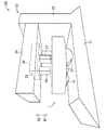
図1は、本発明の実施形態1の自走式掃除機1を側方から見た断面図であり、図2は流路形成部13および吸引部6の分解斜視図である。本実施形態の自走式掃除機1は、自走のための駆動輪2を有する走行駆動部3を備え、前記駆動輪2による走行方向Aの前方に吸引口4が設けられる掃除機本体5と、前記掃除機本体5に設けられ、吸引力を発生する吸引部6であって、発生した吸引力によって外気を吸引可能な第1通気口7を有する吸引部6と、前記掃除機本体5に設けられ、前記吸引部6の吸引力によって吸引された塵埃が貯留される貯留室8であって、外部に開放可能な第2通気口9および前記第1通気口7に空間15を介して接続可能な第3通気口10が形成される貯留室8を有する貯留部11と、前記貯留部11に前記第3通気口10を塞ぐように設けられ、前記貯留室8から前記第3通気口10を介して外部へ塵埃が排出されることを阻止する貯留部用フィルタ12と、前記吸引部6と前記貯留部11との間に設けられる流路形成部13であって、前記第1通気口7と前記第3通気口10とを接続して、前記第1通気口7と前記第3通気口10との間に流路を形成する接続位置と、前記第1通気口7および前記第3通気口10を、前記吸引部6と前記貯留部11との間の前記空間15に臨んで開放させる開放位置とに変位可能に設けられる流路形成部13とを含む。
(Embodiment 1)
FIG. 1 is a sectional view of the self-propelled
前記掃除機本体5は、吸引口4に収容され、駆動輪2に平行な軸線まわりに回転可能に設けられ、自走した経路の塵埃を集塵する回転ブラシ14を有し、回転ブラシ14の集塵によって吸引口4内に巻き込まれた塵埃を貯留部11の貯留室8内に吸引して貯留可能に構成されている。前記第2通気口9には、吸引部6から第1通気口7、流路形成部13および第3通気口10を介して貯留室8内に導かれた吸引力が、前記第2通気口8を介して漏洩することを防止するため、たとえば合成樹脂シートなどの可撓性を有する図示しない弁体が逆止弁として設けられる。この弁体によって、貯留室8内が第2通気口9によって開放されることを防止し、貯留室8に導かれた吸引力が吸引口4に導かれ、より大きな吸引力が得られるように構成されている。
The
前記吸引部6は、前述の回転ブラシ14と、図示しないモータおよび減速機などの回転駆動源とを含んで構成されている。前記流路形成部13は、吸引部6側の開口16によって、吸引部6の第1通気口7に連通するとともに、貯留部11側の開口17によって、貯留部11の第3通気口10に連通する状態で構成されている。
The
また、貯留部11の上部には、第2通気口9が設けられ、貯留部11に貯留された塵埃を、当該第2通気口9を経由して取り出すことができる。
In addition, a
本実施形態1の自走式掃除機1は、前記第2通気口9に外部から塵埃の吸取り装置などを接続することによって、掃除機本体5の外部へ塵埃を排除することができる。また、自走式掃除機1には、第2通気口9が設けられるので、既存の吸引装置によって前記第2通気口9から吸引力を貯留室8内に導き、回収した塵埃を排出することができる。
The self-propelled
次に、実施形態1で述べた自走式掃除機1を用いた自走式掃除装置100を、第2実施形態として図3および図4を用いて説明する。
Next, a self-propelled
(実施形態2)
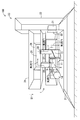
図3は、本発明の実施形態2の自走式掃除装置100の斜視図であり、図4は自走式掃除装置100の手前側を省略した断面斜視図である。図3および図4は、実施形態1の自走式掃除機1が帰還ステーションユニット23に帰還した状態を示している。なお、前述の実施形態1と対応する部分には同一の参照符を付し、重複する説明は省略する。帰還ステーションユニット23の構成について、以下に説明する。
(Embodiment 2)
FIG. 3 is a perspective view of the self-propelled
本実施形態2の自走式掃除装置100は、前述の自走式掃除機1と、自走式掃除機1を乗載可能な帰還台部21および帰還台部21に立設される壁体部22を備える帰還ステーションユニット23とを含む。
The self-propelled
前記帰還ステーションユニット23には、壁体部22に、帰還台部21に近接する方向B1の変位または離反する方向B2の変位が可能であるように構成され、帰還台部21に自走式掃除機1が乗載されると、帰還台部21に近接する方向B1に変位して、自走式掃除機1の吸引部6の吸引力によって前記貯留室8内の塵埃を回収する塵埃回収部24が設けられる。
The
前記塵埃回収部24は、自走式掃除機1から回収した塵埃を収容する収容室25を有する収容部26と、前記収容部26から前記帰還台部21に向かって突出し、塵埃回収部24が帰還台部21に近接する方向B1へ変位することによって、帰還台部21を接続位置から図3および図4に示す開放位置へ変位させて、第1通気口7と収容室25とを連通させる第1ダクト27と、前記収容部26から帰還台部21に向かって突出し、塵埃回収部24が帰還台部21に近接する方向B1へ変位することによって、第2通気口9と収容室25とを連通させる第2ダクト28と、収容部26に前記第1ダクト27を塞ぐように設けられ、収容室25から第1ダクト27内への塵埃の通過を阻止する第1ダクト用フィルタ29とを含む。
The
帰還ステーションユニット23の壁体部22には、充電ユニット31が配設され、自走式掃除機1の後部の充電電極32と接続されることによって、自走式掃除機1に内蔵される充電池が充電され、前記モータなどに電力を供給することができるように構成されている。
A charging
前記塵埃回収部24は、帰還台部21と平行に配置され、その基端部は前記壁体部22に沿って上下方向、すなわち帰還台部21に近接する方向B1および離反する方向B2に移動可能に構成されている。塵埃回収部24の下部には、帰還した自走式掃除機1と接続可能に前述の第1および第2ダクト27,28が設けられている。
The
第1ダクト27および第2ダクト28の上端部は、前述の収容部26に設けられ、収容室25に連通している。収容室25と第1ダクト27との接続部分には、第1ダクト27の前記収容室25に臨む開口を当該収容室25側から塞ぐように、第1ダクト用フィルタ29が配設されている。
The upper ends of the
次に、図5および図6を参照して、自走式掃除装置100による塵埃の除去動作について説明する。
Next, the dust removal operation by the self-propelled
図5は、第1および第2ダクト27,28が帰還した自走式掃除機1に接続された状態を模式的に示す図である。図6は図5に示す接続状態における吸引経路を示す図である。前記帰還ステーションユニット23は、自走式掃除機1が帰還したことを図示しないセンサによって検出すると、塵埃回収部24が壁体部22に沿って帰還台部21に近接する方向B1、すなわち下方に移動し、流路形成部13は第1ダクト27によって下方に押し下げられ、吸引部6の第1通気口7と貯留部11の第3通気口10とが空間15に臨んで開放され、第1通気口7と第3通気口10との接続状態が解除される。
FIG. 5 is a diagram schematically showing a state in which the first and
このように前記第1ダクト27と第2ダクト28とが下降することによって、自走式掃除機1の第1通気口7は、第1ダクト27を介して収容室25に連通し、かつ収容室25は、第2ダクト28を介して塵埃回収部24の第1ダクト27に連通し、自走式掃除機1の第2通気口9と塵埃回収部24の貯留室25とが連通する。
As the
次に、図6を参照して、帰還ステーションユニット23に自走式掃除機1が帰還した状態における塵埃回収時の気流と塵埃の流れについて説明する。自走式掃除機1は、第1通気口7と第1ダクト27とが連通し、第2通気口9と第2ダクト28とが連通したことを、たとえば壁体部22に設けられるリミットスイッチなどのセンサ(図示せず)によって検出すると、吸引部6を作動させ、吸引を開始する。
Next, with reference to FIG. 6, the air flow and the dust flow when collecting dust in the state where the self-propelled
吸引部6が吸引動作を開始すると、主に矢符F1〜F4で示すように気流が生じる。矢符F1は、吸引部6の吸引力が第1通気口7から第1ダクト27を経由して、収容室25に導かれ、これによって収容室25から吸引部6に引き込まれる気流である。矢符F2は、収容室25に導かれた吸引力によって、貯留室8から第2ダクト28を経由して、貯留部11から収容室25に引き込まれる気流である。矢符F3は、回転ブラシ14周辺の外気から貯留室8内に引き込まれる気流である。矢符F4は、吸引部6から外部へ排気される気流である。
When the
塵埃の流れは、次のようになっている。矢符F2の気流の流れによって、貯留部8内の塵埃が収容室25に移動して収集される。矢符F1の流れに対しては、収容室25と第1ダクト27の連結部に第1ダクト用フィルタ29が配設されているので、収容室25に収集された塵埃は、第1ダクト用フィルタ29で濾されて収容室25に残り、第1ダクト27や吸引部6には到達せず、塵埃だけを回収することができる。
The flow of dust is as follows. Due to the flow of the air flow indicated by the arrow F2, dust in the
このような構成によって、自走式掃除機1が自走して貯留室8内に収集した塵埃を、自走式掃除機1自身の吸引機構を用いて、帰還時に自動的に帰還ステーションユニット23の収容室25に収集できるため、帰還ステーションユニット23に塵埃収集用の吸引部を別途備える必要がなく、システム全体の部品点数削減、コストダウンが可能となる。また、第1ダクト用フィルタ29を用いることによって、自走式掃除機1の吸引部6側に塵埃が戻ることを防止することができる。
With such a configuration, the dust collected by the self-propelled
(実施形態3)
図7は、本発明の実施形態3を示す自走式掃除機1を備える自走式掃除装置100aの斜視図であり、図8は自走式掃除装置100aの手前側を省略した断面斜視図である。図7および図8は、実施形態1の自走式掃除機1が帰還ステーションユニット23に帰還した状態を示している。なお、前述の実施形態1,2と対応する部分には同一の参照符を付し、重複する部分の説明は省略する。まず、帰還ステーションユニット23の構成について、以下に説明する。
(Embodiment 3)
FIG. 7 is a perspective view of a self-propelled
本実施形態の自走式掃除装置100aは、前記第1および第2ダクト27,28に加え
て、第3ダクト33が設けられ、前記収容部26には第3ダクト33の連結部分の開口を塞ぐように第3ダクト用フィルタ34が設けられる。このような第3ダクト用フィルタ34によって、収容室25から第3ダクト33内への塵埃の通過を阻止し、収容室25内から第3ダクト33を介して外部へ塵埃が排出されることを防止することができる。
The self-propelled
帰還ステーションユニット23の上部には、塵埃回収部24が配置されている。塵埃回収部24は、前述の実施形態2と同様に、壁体部22に沿って上下方向、すなわち矢符B1,B2方向に移動可能に構成されている。塵埃回収部24の下面24aには、自走式掃除機1と連通可能に前記3本の第1〜第3ダクト27,28,33が平行に設けられている。
A
帰還ステーションユニット23は、帰還台部21と壁体部22を有する。壁体部22には充電ユニット31が配設され、自走式掃除機1の後部の充電電極32と電気的に接続し
て、自走式掃除機1に搭載される蓄電池を帰還するたびに充電するように構成されている。
The
帰還ステーションユニット23の上部には前述と同様に収容室25が設けられ、収容室25の下部から第1ダクト27、第2ダクト28、第3ダクト33が下方に突出して形成されている。すなわち、前記自走式掃除機1の第1通気口7に連通される第1ダクト27と、前記自走式掃除機1の第2通気口9に連通される第2ダクト28に加え、第3通気口10に連通される第3ダクト33をさらに有している点である。収容室25と第1ダクト27の連結部には、第3ダクト用フィルタ34が配置されている。
A
次に、図9および図10を参照して、実施形態3の自走式掃除装置100aによる塵埃の除去(排出)について具体的に説明する。
Next, with reference to FIG. 9 and FIG. 10, the removal (discharge) of dust by the self-propelled
図9は、第1〜第3ダクト27,28,33が帰還した自走式掃除機1に接続された状態を模式的に示す図であり、図10は第1〜第3ダクト27,28,33が帰還した自走式掃除機1に接続された状態における気流F11〜F15を示す図である。
FIG. 9 is a diagram schematically illustrating a state in which the first to
帰還ステーションユニット23は、自走式掃除機1の帰還を確認した上で、塵埃回収部24が壁体部22に沿って下方に移動することで、流路形成部9が下方に押し下げられ、吸引部6の第1通気口7および貯留部11の第3通気口10が開放される。
The
第3ダクト33、第1ダクト27および第2ダクト28が下降することで、自走式掃除機1の貯留部11に設けた第3通気口10と塵埃回収部24の第3ダクト33が連通し、第1通気口7と第1ダクト27が連通し、第2通気口9と第2ダクト28が連通する。
When the
図9を参照して、帰還ステーションユニット23での帰還状態における塵埃の除去(排出)時の気流と塵埃の流れについて説明する。自走式掃除機1は、第3通気口10と第3ダクト33が連通し、第1通気口7と第1ダクト27および、第2通気口9と第2ダクト28が連通したことを検出すると、自身の吸引部6を作動させ、吸引を開始する。
With reference to FIG. 9, the air flow and the dust flow when the dust is removed (discharged) in the return state in the
吸引を開始すると、主に矢符F11〜F15の気流が生じる。矢符F11は、吸引部6が第1ダクト27を経由して、収容室25から吸引部6側に引き込む気流である。矢符F12は、第2ダクト28を経由して貯留部11から収容室25に引き込まれる気流である。矢符F13は、ブラシ1周辺の外気から貯留部11に引き込まれる気流である。矢符F14は、吸引部6から外部へ排気される気流である。
When the suction is started, an air flow of arrows F11 to F15 is mainly generated. An arrow F <b> 11 is an air flow that the
実施形態2と異なるのは、第3通気口10から第3ダクト33を経由して、貯留部11に流れる矢符F15の気流が生じる点である。この矢符F15で示す気流が収容室25から貯留部11側に生じることにで、貯留部11から収容室25への気流および塵埃の移動を助長することができるとともに、自走式掃除機1の第1ダクト用フィルタ29に対して通常の掃除機としての使用時と、逆方向の気流が生じることから、第1ダクト用フィルタ29の清掃が可能となり、フィルタの目詰まりなどを改善することができる。
The difference from the second embodiment is that an air flow of an arrow F15 flowing from the
本発明は、掃除機内部に貯留された塵埃を、効率的に充電機能を備える帰還ユニットに集積する装置を提供するものであり、充電機能を持つ掃除機一般に利用可能である。 The present invention provides an apparatus that efficiently accumulates dust stored in a vacuum cleaner in a feedback unit having a charging function, and can be used for general vacuum cleaners having a charging function.
1 自走式掃除機
2 駆動輪
3 走行駆動部
4 吸引口
5 掃除機本体
6 吸引部
7 第1通気口
8 貯留室
9 第2通気口
10 第3通気口
11 貯留部
12 貯留部用フィルタ
13 流路形成部
14 回転ブラシ
15 空間
16,17 開口
27 第1ダクト
28 第2ダクト
33 第3ダクト
DESCRIPTION OF
Claims (4)
回転ブラシによって巻き込まれた塵埃を吸引する吸引口と、
吸引力を発生する吸引部と、
塵埃が貯留される貯留室と、を備え、
前記吸引部の作動時に、前記吸引口から塵埃を流入させて貯留室内に貯留する場合と、貯留した塵埃を前記吸引部の吸引力により前記吸引口から引き込まれる気流のみを用いて貯留室外に排出する場合と、を有することを特徴とする自走式掃除機。 A travel drive having drive wheels;
A suction port for sucking dust caught in the rotating brush;
A suction part that generates a suction force;
A storage chamber for storing dust,
During operation of the suction part, when dust is introduced from the suction port and stored in the storage chamber, the stored dust is discharged outside the storage chamber using only the airflow drawn from the suction port by the suction force of the suction unit. And a self-propelled vacuum cleaner characterized by comprising:
回転ブラシによって巻き込まれた塵埃を吸引する吸引口と、
吸引力を発生する吸引部と、
塵埃が貯留される貯留室と、を含む自走式掃除機と、
前記自走式掃除機の貯留室から塵埃を回収する塵埃回収部を含む帰還ステーションと、を備え、
前記貯留室は複数の通気口を有し、
前記自走式掃除機が掃除を行う際には、前記吸引部を作動して前記吸引口から第一の通気口を経て前記貯留室に塵埃を流入させ、前記自走式掃除機が帰還ステーションに帰還した際には、前記吸引部を作動して、前記吸引口から引き込まれる気流のみを用いて、貯留した塵埃を第一の通気口とは異なる第二の通気口から前記塵埃回収部へ前記吸引部の吸引力により移動させることを特徴とする自走式掃除装置。 A travel drive having drive wheels;
A suction port for sucking dust caught in the rotating brush;
A suction part that generates a suction force;
A self-propelled vacuum cleaner including a storage chamber in which dust is stored;
A return station including a dust collection unit for collecting dust from a storage chamber of the self-propelled cleaner, and
The storage chamber has a plurality of vents;
When the self-propelled cleaner performs cleaning, the suction unit is operated to allow dust to flow into the storage chamber from the suction port through the first vent, and the self-propelled cleaner is returned to the return station. When returning to the factory, the suction unit is operated to use only the airflow drawn from the suction port, and the stored dust is transferred from the second ventilation port different from the first ventilation port to the dust collection unit. The self-propelled cleaning device is moved by the suction force of the suction part.
少なくとも自走式掃除機が帰還している間は、前記自走式掃除機に電力を供給可能に構成されていることを特徴とする請求項2または3のいずれかに記載の自走式掃除装置。 The return station includes a charging unit that supplies power to the self-propelled cleaner,
4. The self-propelled cleaner according to claim 2, wherein power is supplied to the self-propelled cleaner at least while the self-propelled cleaner is returning. 5. apparatus.
Priority Applications (1)
| Application Number | Priority Date | Filing Date | Title |
|---|---|---|---|
| JP2016141154A JP6463305B2 (en) | 2016-07-19 | 2016-07-19 | Self-propelled cleaner and self-propelled cleaner |
Applications Claiming Priority (1)
| Application Number | Priority Date | Filing Date | Title |
|---|---|---|---|
| JP2016141154A JP6463305B2 (en) | 2016-07-19 | 2016-07-19 | Self-propelled cleaner and self-propelled cleaner |
Related Parent Applications (1)
| Application Number | Title | Priority Date | Filing Date |
|---|---|---|---|
| JP2013002165A Division JP6047406B2 (en) | 2013-01-09 | 2013-01-09 | Self-propelled cleaner and self-propelled cleaner |
Publications (3)
| Publication Number | Publication Date |
|---|---|
| JP2016193244A JP2016193244A (en) | 2016-11-17 |
| JP2016193244A5 JP2016193244A5 (en) | 2017-03-16 |
| JP6463305B2 true JP6463305B2 (en) | 2019-01-30 |
Family
ID=57323340
Family Applications (1)
| Application Number | Title | Priority Date | Filing Date |
|---|---|---|---|
| JP2016141154A Expired - Fee Related JP6463305B2 (en) | 2016-07-19 | 2016-07-19 | Self-propelled cleaner and self-propelled cleaner |
Country Status (1)
| Country | Link |
|---|---|
| JP (1) | JP6463305B2 (en) |
Family Cites Families (10)
| Publication number | Priority date | Publication date | Assignee | Title |
|---|---|---|---|---|
| JP3986310B2 (en) * | 2001-12-19 | 2007-10-03 | シャープ株式会社 | Parent-child type vacuum cleaner |
| JP4123857B2 (en) * | 2002-07-31 | 2008-07-23 | 松下電器産業株式会社 | Electric vacuum cleaner |
| JP2004267236A (en) * | 2003-03-05 | 2004-09-30 | Hitachi Ltd | Self-traveling type vacuum cleaner and charging device used for the same |
| JP4205466B2 (en) * | 2003-03-20 | 2009-01-07 | 日立アプライアンス株式会社 | Electric vacuum cleaner |
| KR20070074146A (en) * | 2006-01-06 | 2007-07-12 | 삼성전자주식회사 | Cleaner system |
| JP4939885B2 (en) * | 2006-09-28 | 2012-05-30 | 株式会社東芝 | Electric vacuum cleaner |
| KR101330734B1 (en) * | 2007-08-24 | 2013-11-20 | 삼성전자주식회사 | Robot cleaner system having robot cleaner and docking station |
| JP5011145B2 (en) * | 2008-02-04 | 2012-08-29 | 株式会社日立製作所 | Charger for self-propelled vacuum cleaner |
| JP6010722B2 (en) * | 2010-08-01 | 2016-10-19 | ライフラボ株式会社 | Robot vacuum cleaner, dust discharge station and multi-stage cyclone vacuum cleaner |
| JP5758188B2 (en) * | 2011-04-28 | 2015-08-05 | 株式会社東芝 | Electric vacuum cleaner |
-
2016
- 2016-07-19 JP JP2016141154A patent/JP6463305B2/en not_active Expired - Fee Related
Also Published As
| Publication number | Publication date |
|---|---|
| JP2016193244A (en) | 2016-11-17 |
Similar Documents
| Publication | Publication Date | Title |
|---|---|---|
| EP3209175B1 (en) | Handheld vacuum cleaner | |
| CN113226142B (en) | Robot cleaner, station and cleaning system | |
| JP6522905B2 (en) | Electric vacuum cleaner | |
| TWI683644B (en) | Base station for a vacuum cleaner | |
| WO2017047291A1 (en) | Electric cleaning device | |
| EP2305089A1 (en) | Electric cleaner | |
| WO2016002894A1 (en) | Electric vacuum cleaner | |
| JP2017164026A (en) | Handy vacuum cleaner | |
| WO2021100296A1 (en) | Electric vacuum cleaner | |
| JP6548875B2 (en) | Dust collector and vacuum cleaner | |
| KR101667716B1 (en) | Robot cleaner | |
| KR20140041905A (en) | Cleaning robot | |
| US20230136405A1 (en) | Vacuum cleaner | |
| JP6489893B2 (en) | Electric vacuum cleaner | |
| JP2020146173A (en) | Vacuum cleaner and suction port body thereof | |
| JP6047406B2 (en) | Self-propelled cleaner and self-propelled cleaner | |
| JP6463305B2 (en) | Self-propelled cleaner and self-propelled cleaner | |
| JP6707341B2 (en) | Electric cleaning device | |
| JP3920200B2 (en) | Electric vacuum cleaner | |
| JP2017104335A (en) | Vacuum cleaner | |
| JP6904659B2 (en) | Electric cleaning device | |
| CN109717793B (en) | Electric vacuum cleaner | |
| JP2014023782A (en) | Vacuum cleaner | |
| JP2024051859A (en) | Vacuum cleaner suction tool | |
| JP2014132974A5 (en) |
Legal Events
| Date | Code | Title | Description |
|---|---|---|---|
| RD02 | Notification of acceptance of power of attorney |
Free format text: JAPANESE INTERMEDIATE CODE: A7422 Effective date: 20161104 |
|
| A521 | Request for written amendment filed |
Free format text: JAPANESE INTERMEDIATE CODE: A523 Effective date: 20170209 |
|
| A977 | Report on retrieval |
Free format text: JAPANESE INTERMEDIATE CODE: A971007 Effective date: 20170321 |
|
| A131 | Notification of reasons for refusal |
Free format text: JAPANESE INTERMEDIATE CODE: A131 Effective date: 20170328 |
|
| A521 | Request for written amendment filed |
Free format text: JAPANESE INTERMEDIATE CODE: A523 Effective date: 20170526 |
|
| A131 | Notification of reasons for refusal |
Free format text: JAPANESE INTERMEDIATE CODE: A131 Effective date: 20171107 |
|
| A521 | Request for written amendment filed |
Free format text: JAPANESE INTERMEDIATE CODE: A523 Effective date: 20171228 |
|
| A02 | Decision of refusal |
Free format text: JAPANESE INTERMEDIATE CODE: A02 Effective date: 20180605 |
|
| A521 | Request for written amendment filed |
Free format text: JAPANESE INTERMEDIATE CODE: A523 Effective date: 20180828 |
|
| A911 | Transfer to examiner for re-examination before appeal (zenchi) |
Free format text: JAPANESE INTERMEDIATE CODE: A911 Effective date: 20180904 |
|
| A131 | Notification of reasons for refusal |
Free format text: JAPANESE INTERMEDIATE CODE: A131 Effective date: 20181106 |
|
| A521 | Request for written amendment filed |
Free format text: JAPANESE INTERMEDIATE CODE: A523 Effective date: 20181112 |
|
| TRDD | Decision of grant or rejection written | ||
| A01 | Written decision to grant a patent or to grant a registration (utility model) |
Free format text: JAPANESE INTERMEDIATE CODE: A01 Effective date: 20181204 |
|
| A61 | First payment of annual fees (during grant procedure) |
Free format text: JAPANESE INTERMEDIATE CODE: A61 Effective date: 20181228 |
|
| R150 | Certificate of patent or registration of utility model |
Ref document number: 6463305 Country of ref document: JP Free format text: JAPANESE INTERMEDIATE CODE: R150 |
|
| LAPS | Cancellation because of no payment of annual fees |