JP6461558B2 - Overhead door - Google Patents

Overhead door Download PDF

Info

Publication number
JP6461558B2
JP6461558B2 JP2014221136A JP2014221136A JP6461558B2 JP 6461558 B2 JP6461558 B2 JP 6461558B2 JP 2014221136 A JP2014221136 A JP 2014221136A JP 2014221136 A JP2014221136 A JP 2014221136A JP 6461558 B2 JP6461558 B2 JP 6461558B2
Authority
JP
Japan
Prior art keywords
hinge
pair
guide rails
bearing
connecting body
Prior art date
Legal status (The legal status is an assumption and is not a legal conclusion. Google has not performed a legal analysis and makes no representation as to the accuracy of the status listed.)
Active
Application number
JP2014221136A
Other languages
Japanese (ja)
Other versions
JP2016089359A (en
JP2016089359A5 (en
Inventor
植竹 徹
徹 植竹
Current Assignee (The listed assignees may be inaccurate. Google has not performed a legal analysis and makes no representation or warranty as to the accuracy of the list.)
Bunka Shutter Co Ltd
Original Assignee
Bunka Shutter Co Ltd
Priority date (The priority date is an assumption and is not a legal conclusion. Google has not performed a legal analysis and makes no representation as to the accuracy of the date listed.)
Filing date
Publication date
Application filed by Bunka Shutter Co Ltd filed Critical Bunka Shutter Co Ltd
Priority to JP2014221136A priority Critical patent/JP6461558B2/en
Publication of JP2016089359A publication Critical patent/JP2016089359A/en
Publication of JP2016089359A5 publication Critical patent/JP2016089359A5/ja
Application granted granted Critical
Publication of JP6461558B2 publication Critical patent/JP6461558B2/en
Active legal-status Critical Current
Anticipated expiration legal-status Critical

Links

Images

Description

本発明は、建物の開口部及びその直上の天井部に設置された一対のガイドレールに沿って、複数のパネルからなるパネル連接体を移動させて開口部を開閉するためのオーバーヘッドドアに関する。   The present invention relates to an overhead door for opening and closing an opening by moving a panel connecting body composed of a plurality of panels along a pair of guide rails installed on an opening of a building and a ceiling portion directly above the opening.

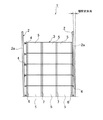
オーバーヘッドドアとしては、例えば、図1に示す構成を有するものが知られている。
図1(a)及び図1(b)は、オーバーヘッドドアの構成を建物内部から視て示す図であり、(a)は正面図であり、(b)は(a)におけるガイドレールの構成を示す側面図である。
オーバーヘッドドア1は、一対のガイドレール2、2と、矩形状のパネル連接体3と、複数のガイドローラ部材4とから概略構成されている。
両ガイドレール2、2は、建物の開口部(図示せず)を挟む両脇の位置に、互いに平行に配設され、且つ、その開口部からその直上の天井部(図示せず)まで延在する断面略L字状の案内部材である。各ガイドレール2は、開口部(図示せず)の両脇の床部(図示せず)に設置された垂直レール2aと、天井部(図示せず)に設置された水平レール2bと、これらの両レール2a、2bを連絡する湾曲レール2cとから構成されている。
パネル連接体3は、垂直レール2aの長さ方向に積層してなる複数の矩形状のパネル5と、これら複数のパネル5が湾曲レール2cを移動できるように、隣接するパネル5同士を旋回可能に接合する複数のヒンジ(図示せず)を有しており、全体として大きな矩形状をなす組立体である。各パネル5は、上記長さ方向に直交する方向に延在する細長い矩形状の板部材であり、各パネル5の両端の内面(以下、内面というときは、開口部から建物の内部を向く面をいうものとする。)上には、それぞれ、上記積層方向に延在する縦框部6が配設されており、これら縦框部6間のパネル5の内面上には、縦框部6と平行に延在する複数(図1では二つ)の框補強部7が等間隔に配設されている。隣接するパネル5の両縦框部6の内面上には、両縦框部6を介して当該パネル5同士を旋回可能に接合するサイドヒンジ(図示せず)が配設されており、隣接するパネル5の両框補強部7の内面上には、両框補強部7を介して当該パネル5同士を旋回可能に接合する中間ヒンジ(図示せず)が配設されている。
ガイドローラ部材4は、パネル連接体3の両縦框部6から一対のガイドレール2、2に向けて延在し、且つ、その一対のガイドレール2、2を走行する部材である。
このように構成されたオーバーヘッドドア1は、パネル連接体3が垂直レール2a間に停止し、開口部(図示せず)を塞いでいる「閉」状態と、パネル連接体3が垂直レール2aから湾曲レール2cを経て水平レール2bへ移動して開口部(図示せず)の閉鎖を解いて、その水平レール2b間に停止している「開」状態をとることができる。
As an overhead door, for example, one having a configuration shown in FIG. 1 is known.
1 (a) and 1 (b) are diagrams showing the configuration of an overhead door as viewed from the inside of a building, (a) is a front view, and (b) is the configuration of a guide rail in (a). FIG.
The overhead door 1 is generally composed of a pair of guide rails 2, 2, a rectangular panel connecting body 3, and a plurality of guide roller members 4.
The two guide rails 2 and 2 are arranged in parallel to each other at positions on both sides of an opening (not shown) of the building, and extend from the opening to a ceiling (not shown) immediately above the opening. It is a guide member having a substantially L-shaped cross section. Each guide rail 2 includes a vertical rail 2a installed on a floor (not shown) on both sides of an opening (not shown), a horizontal rail 2b installed on a ceiling (not shown), And the curved rail 2c connecting the two rails 2a and 2b.
The panel connecting body 3 can swivel between adjacent panels 5 so that the plurality of rectangular panels 5 stacked in the length direction of the vertical rail 2a and the plurality of panels 5 can move on the curved rail 2c. The assembly has a plurality of hinges (not shown) that are joined to each other and has a large rectangular shape as a whole. Each panel 5 is an elongated rectangular plate member extending in a direction orthogonal to the length direction, and the inner surfaces of the both ends of each panel 5 (hereinafter referred to as inner surfaces when facing from the opening to the interior of the building) On the upper side, the vertical hooks 6 extending in the laminating direction are disposed, and the vertical hooks 6 are provided on the inner surface of the panel 5 between the vertical hooks 6. A plurality of (two in FIG. 1) wrinkle reinforcement portions 7 extending in parallel with each other are arranged at equal intervals. Side hinges (not shown) are provided on the inner surfaces of the two vertical flanges 6 of the adjacent panels 5 so as to be able to turn the panels 5 together via the vertical vertical flanges 6. An intermediate hinge (not shown) is provided on the inner surface of the both-side reinforcement portion 7 of the panel 5 so that the panels 5 are pivotably joined to each other via the both-side reinforcement portion 7.
The guide roller member 4 is a member that extends from both vertical flange portions 6 of the panel connecting body 3 toward the pair of guide rails 2 and 2 and travels through the pair of guide rails 2 and 2.
In the overhead door 1 configured in this manner, the panel connecting body 3 is stopped between the vertical rails 2a and the opening (not shown) is closed, and the panel connecting body 3 is separated from the vertical rail 2a. By moving to the horizontal rail 2b via the curved rail 2c, the opening (not shown) is unblocked, and an "open" state where the horizontal rail 2b is stopped can be taken.

特開2004−116001号公報JP 2004-116001 A

図2は、オーバーヘッドドア1の一対のガイドレール2、2がそのガイドレール2、2を含む面内の水平方向に層間変形した状態を示す正面図である。
図2に示すオーバーヘッドドア1は、地震等の振動のエネルギーに由来する、横方向(例えば水平方向)に働く外力を受けることによって、建物の開口部(図示せず)の変形に伴って、一対のガイドレール2、2の各垂直レール2aがその垂直レール2aを含む面内の水平方向(図2では左方向)に層間変形することがある。この場合、図2に向かって、パネル連接体3の右端と、上部が左方向に傾斜した右側の垂直レール2aとの間隔は上方にいくほど狭くなる。この状態で、パネル連接体3を上方移動させようとしても、パネル連接体3の、例えば右端最上部の縦框部6に取り付けられたガイドローラ部材4が右側の垂直レール2aに対して過度に接触し、その走行が規制されるため、オーバーヘッドドア1を開けることができない。このような状態では、ユーザーが建物内に閉じ込められるため、その退避行動が制限され、あるいは、物品の搬出入作業に支障が生じる可能性がある。
また、パネル連接体3が実質的に変形不可能な「剛構造」であるため、例えば水平方向の振幅が大きな外力を受け続けた場合、垂直レール2aとの過度な接触状態にあるガイドローラ部材4の変形や破損を招き、さらにパネル5やヒンジ(図示せず)の変形や破損に至る可能性もある。
FIG. 2 is a front view showing a state in which the pair of guide rails 2, 2 of the overhead door 1 is deformed between layers in the horizontal direction within the plane including the guide rails 2, 2.
The overhead door 1 shown in FIG. 2 receives a pair of external doors (not shown) that are deformed by receiving an external force acting in the lateral direction (for example, the horizontal direction) derived from the energy of vibration such as an earthquake. Each of the vertical rails 2a of the guide rails 2 and 2 may be deformed between layers in the horizontal direction (left direction in FIG. 2) in the plane including the vertical rail 2a. In this case, the distance between the right end of the panel connecting body 3 and the right vertical rail 2a whose upper part is inclined leftward becomes narrower toward the upper side in FIG. In this state, even if the panel connecting body 3 is to be moved upward, the guide roller member 4 attached to, for example, the vertical flange 6 at the uppermost right end of the panel connecting body 3 is excessively moved with respect to the right vertical rail 2a. The overhead door 1 cannot be opened because it is in contact with and is restricted from traveling. In such a state, since the user is confined in the building, the evacuation behavior is limited, or there is a possibility that the work for carrying in / out the article may be hindered.
Further, since the panel connecting body 3 has a “rigid structure” that is substantially undeformable, for example, when a horizontal force continues to receive a large external force, the guide roller member is in an excessive contact state with the vertical rail 2a. 4 may be deformed or damaged, and the panel 5 or the hinge (not shown) may be deformed or damaged.

本発明は、上述した問題点に鑑みてなされたものであり、例えば、地震等の影響によりガイドレールが水平方向に層間変形した状態であっても、ガイドローラ部材等の部品の変形や破損の発生を招きにくく、その層間変形した一対のガイドレールに沿ってパネル連接体を移動させることができるオーバーヘッドドアを提供することを目的とする。   The present invention has been made in view of the above-described problems. For example, even when the guide rail is horizontally deformed due to the influence of an earthquake or the like, deformation or breakage of parts such as the guide roller member is caused. It is an object of the present invention to provide an overhead door that is less likely to be generated and can move a panel connecting body along a pair of guide rails deformed between the layers.

本発明に係るオーバーヘッドドアは、建物の開口部を挟む両脇の位置に、互いに平行に配設され、且つ、該開口部からその直上の天井部まで延在する一対のガイドレールと、該一対のガイドレールの長さ方向に積層してなる複数のパネル及び該複数のパネルのうち、隣接するパネル同士を旋回可能に接合するヒンジを有するパネル連接体と、該パネル連接体の両端からそれぞれ前記一対のガイドレールに向けて延在し、且つ、前記一対のガイドレールを走行する複数のガイドローラ部材を有するオーバーヘッドドアにおいて、
前記ヒンジは、前記パネル連接体の両端に設けられたサイドヒンジと、前記パネル連接体の両端から離れた位置に設けられた中間ヒンジを含み、
前記各サイドヒンジ及び前記各中間ヒンジは、前記一対のガイドレールに向けて延在するヒンジ用軸と、該ヒンジ用軸を旋回可能に支持する第一の軸受を有し、且つ、隣接するパネルのうち一方に配設された第一の軸受部材と、前記ヒンジ用軸を旋回可能に支持する第二の軸受を有し、且つ、隣接するパネルのうち他方に配設された第二の軸受部材と、前記第一の軸受と前記第二の軸受との間の前記ヒンジ用軸上に形成された少なくとも一つの空間を有し、
前記各サイドヒンジは、前記空間内の前記ヒンジ用軸に配設された圧縮ばねをさらに有し、
前記一対のガイドレールが、該一対のガイドレールを含む面内の水平方向に層間変形したときに、前記圧縮ばねの付勢力に抗して、隣接するパネルが互いに独立して前記ヒンジ軸の軸方向に沿って、前記空間の長さ分、移動可能となることを特徴とする。
An overhead door according to the present invention includes a pair of guide rails that are arranged in parallel to each other at positions on both sides of an opening of a building and extend from the opening to a ceiling portion directly above the pair of guide rails. A plurality of panels laminated in the length direction of the guide rail, and a panel connecting body having a hinge that joins adjacent panels so as to be pivotable among the plurality of panels, respectively, from both ends of the panel connecting body In an overhead door that extends toward a pair of guide rails and has a plurality of guide roller members that run on the pair of guide rails,
The hinge includes a side hinge provided at both ends of the panel connecting body, and an intermediate hinge provided at a position away from both ends of the panel connecting body,
Each of the side hinges and each of the intermediate hinges has a hinge shaft extending toward the pair of guide rails, and a first bearing that rotatably supports the hinge shaft, and adjacent panels. A second bearing disposed on the other of the adjacent panels, and a first bearing member disposed on one of the panels and a second bearing for pivotally supporting the hinge shaft. A member and at least one space formed on the hinge shaft between the first bearing and the second bearing;
Each of the side hinges further includes a compression spring disposed on the hinge shaft in the space,
When the pair of guide rails are deformed between layers in the horizontal direction in the plane including the pair of guide rails, the adjacent panels are independent from each other against the biasing force of the compression spring, and the axis of the hinge shaft It is possible to move along the direction by the length of the space.

本発明に係るオーバーヘッドドアは、前記圧縮ばねの両端のうち、少なくとも一方に配設されたワッシャをさらに有することを特徴とする。   The overhead door according to the present invention further includes a washer disposed on at least one of both ends of the compression spring.

本発明に係るオーバーヘッドドアは、前記ガイドローラ部材が前記パネル連接体の両端の上部及び下部に設置されている場合、該ガイドローラ部材は、前記一対のガイドレールを走行するガイドローラと、該ガイドローラを支持し、且つ、前記一対のガイドレールに向けて延在するガイドローラ用軸と、該ガイドローラ用軸を回転可能に支持する軸受と、前記ガイドローラ軸に取り付けられたワッシャと、該ワッシャと前記ガイドローラとの間に配設された圧縮ばねを有することを特徴とする。   In the overhead door according to the present invention, when the guide roller members are installed at the upper and lower portions of both ends of the panel connecting body, the guide roller members include a guide roller that travels on the pair of guide rails, and the guide A guide roller shaft that supports the roller and extends toward the pair of guide rails, a bearing that rotatably supports the guide roller shaft, a washer attached to the guide roller shaft, A compression spring is disposed between the washer and the guide roller.

本発明に係るオーバーヘッドドアは、建物の開口部を挟む両脇の位置に、互いに平行に配設され、且つ、該開口部からその直上の天井部まで延在する一対のガイドレールと、該一対のガイドレールの長さ方向に積層してなる複数のパネル及び該複数のパネルのうち、隣接するパネル同士を旋回可能に接合するヒンジを有するパネル連接体と、該パネル連接体の両端から前記一対のガイドレールに向けて延在し、且つ、前記一対のガイドレールを走行する複数のガイドローラ部材を有する。ヒンジは、パネル連接体の両端に設けられたサイドヒンジと、パネル連接体の両端から離れた位置に設けられた中間ヒンジを含み、各サイドヒンジ及び各中間ヒンジは、一対のガイドレールに向けて延在するヒンジ用軸と、該ヒンジ用軸を旋回可能に支持する第一の軸受を有し、且つ、隣接するパネルのうち一方に配設された第一の軸受部材と、ヒンジ用軸を旋回可能に支持する第二の軸受を有し、且つ、隣接するパネルのうち他方に配設された第二の軸受部材と、第一の軸受と前記第二の軸受との間のヒンジ用軸上に形成された少なくとも一つの空間を有し、各サイドヒンジは、空間内のヒンジ用軸に配設された圧縮ばねをさらに有している。このため、一対のガイドレールが、該一対のガイドレールを含む面内の水平方向に層間変形したときに、圧縮ばねの付勢力に抗して、隣接するパネルが互いに独立してヒンジ軸の軸方向に沿って、前記空間の長さ分、移動可能となる。これによって、層間変形した一対のガイドレールの変形後の形状に合わせて、パネル連接体を変形させることができる。このパネル連接体が変形した状態では、ガイドローラ部材4とガイドレール2との過度な接触を緩和でき、層間変形した一対のガイドレールに沿う、パネル連接体の円滑な移動を確保できるので、オーバーヘッドドアを開けることができる。   An overhead door according to the present invention includes a pair of guide rails that are arranged in parallel to each other at positions on both sides of an opening of a building and extend from the opening to a ceiling portion directly above the pair of guide rails. A plurality of panels laminated in the length direction of the guide rail, a panel connecting body having a hinge for rotatably joining adjacent panels among the plurality of panels, and the pair from the both ends of the panel connecting body And a plurality of guide roller members that run on the pair of guide rails. The hinge includes a side hinge provided at both ends of the panel connecting body and an intermediate hinge provided at a position away from both ends of the panel connecting body. Each side hinge and each intermediate hinge are directed toward a pair of guide rails. An extending hinge shaft, a first bearing for pivotally supporting the hinge shaft, and a first bearing member disposed on one of adjacent panels, and the hinge shaft A second bearing member that is pivotally supported and has a second bearing member disposed on the other of the adjacent panels, and a hinge shaft between the first bearing and the second bearing Each side hinge further includes a compression spring disposed on a hinge shaft in the space. For this reason, when the pair of guide rails are deformed between layers in the horizontal direction in the plane including the pair of guide rails, the adjacent panels are independent of each other against the biasing force of the compression spring, and the axis of the hinge shaft is independent of each other. It can move along the direction by the length of the space. Accordingly, the panel connecting body can be deformed in accordance with the deformed shape of the pair of guide rails deformed between the layers. In a state where the panel connecting body is deformed, excessive contact between the guide roller member 4 and the guide rail 2 can be alleviated, and smooth movement of the panel connecting body along the pair of guide rails deformed between the layers can be secured. You can open the door.

また、本発明に係るオーバーヘッドドアによれば、一対のガイドレールの層間変形後の形状に合わせて、パネル連接体を変形させることができるので、ガイドローラ部材とガイドレールとの過度な接触を緩和でき、ガイドローラ部材等の部品の変形や破損の発生を招きにくく、これにより、例えば、地震等の発生後における補修作業を軽微に済ませることができる。   In addition, according to the overhead door according to the present invention, the panel connecting body can be deformed in accordance with the shape after the interlayer deformation of the pair of guide rails, so that excessive contact between the guide roller member and the guide rail is reduced. This is unlikely to cause deformation or breakage of parts such as the guide roller member, so that, for example, repair work after the occurrence of an earthquake or the like can be lightly completed.

さらに、本発明に係るオーバーヘッドドアによれば、一対のガイドレールの層間変形が補修等により回復して元の形状に戻った場合には、圧縮ばねの付勢力によって、隣接するパネルがヒンジ用軸の軸方向に沿って、空間の長さ分、移動して、パネル連接体を元の形状に復元できる。これによって、ガイドレールに沿う、パネル連接体の円滑な移動を確保できるので、オーバーヘッドドアを開閉できる。   Further, according to the overhead door according to the present invention, when the interlayer deformation of the pair of guide rails is recovered by repair or the like and returns to the original shape, the adjacent panel is moved to the hinge shaft by the biasing force of the compression spring. The panel connecting body can be restored to its original shape by moving by the length of the space along the axial direction. Thereby, since the smooth movement of the panel connecting body along the guide rail can be ensured, the overhead door can be opened and closed.

(a)及び(b)は、オーバーヘッドドアの構成を建物内部から視て示す図であり、(a)は正面図であり、(b)は(a)におけるガイドレールの構成を示す側面図である。(A) And (b) is a figure which shows the structure of an overhead door seeing from the inside of a building, (a) is a front view, (b) is a side view which shows the structure of the guide rail in (a). is there. 図1に示したオーバーヘッドドアのガイドレールがそのガイドレールを含む面内の水平方向に層間変形した状態を示す正面図である。FIG. 2 is a front view showing a state in which the guide rail of the overhead door shown in FIG. 1 is deformed between layers in a horizontal direction within a plane including the guide rail. (a)及び(b)は、本発明の実施の形態1によるオーバーヘッドドアの構成を建物内部から視て示す図であり、(a)はパネル連接体の正面図であり、(b)はパネル連接体の側面図である。(A) And (b) is a figure which shows the structure of the overhead door by Embodiment 1 of this invention seeing from the inside of a building, (a) is a front view of a panel connection body, (b) is a panel. It is a side view of a connection body. (a)及び(b)は、図3(a)及び図3(b)に示したパネル連接体に設けられた上サイドヒンジの構成を示す図であり、(a)は正面図であり、(b)は側面図である。(A) And (b) is a figure which shows the structure of the upper side hinge provided in the panel connection body shown to Fig.3 (a) and FIG.3 (b), (a) is a front view, (B) is a side view. (a)及び(b)は、図3(a)及び図3(b)に示したパネル連接体に設けられた下サイドヒンジの構成を示す図であり、(a)は正面図であり、(b)は側面図である。(A) And (b) is a figure which shows the structure of the lower side hinge provided in the panel connection body shown to Fig.3 (a) and FIG.3 (b), (a) is a front view, (B) is a side view. (a)及び(b)は、図3(a)及び図3(b)に示したパネル連接体に設けられた中サイドヒンジの構成を示す図であり、(a)は正面図であり、(b)は側面図である。(A) And (b) is a figure which shows the structure of the middle side hinge provided in the panel connection body shown to Fig.3 (a) and FIG.3 (b), (a) is a front view, (B) is a side view. (a)及び(b)は、図3(a)及び図3(b)に示したパネル連接体に設けられた中間ヒンジの構成を示す図であり、(a)は正面図であり、(b)は(a)のA−A線断面図である。(A) And (b) is a figure which shows the structure of the intermediate | middle hinge provided in the panel connection body shown to Fig.3 (a) and FIG.3 (b), (a) is a front view, ( (b) is the sectional view on the AA line of (a). (a)及び(b)は、図3(a)及び図3(b)に示したパネル連接体に設けられた他の中間ヒンジの構成を示す図であり、(a)は正面図であり、(b)は(a)のB−B線断面図である。(A) And (b) is a figure which shows the structure of the other intermediate hinge provided in the panel connection body shown to Fig.3 (a) and FIG.3 (b), (a) is a front view. (B) is the BB sectional drawing of (a). 図3〜図8に示した本発明の実施の形態1によるオーバーヘッドドアのガイドレールがそのガイドレールを含む面内の水平方向に層間変形した状態を示す正面図である。FIG. 9 is a front view showing a state where the guide rail of the overhead door according to the first embodiment of the present invention shown in FIGS. 3 to 8 is deformed between layers in the horizontal direction in the plane including the guide rail.

実施の形態1.
本発明の実施の形態1によるオーバーヘッドドアについて、図1、図3〜図9を参照して説明する。但し、その説明においては、図1及び図2と同一構成要素には同一符号を付して重複説明を省略する。
この実施の形態1によるオーバーヘッドドア10は、一対のガイドレール2、2の各垂直レール2aがその垂直レール2aを含む面内の水平方向に層間変形したときに、その垂直レール2aの変形後の形状に合わせて変形できるパネル連接体11を有する点に特徴がある。尚、以下において、単に、内面というときは、建物の開口部(図示せず)の内部を向く面をいうものとする。
ガイドレール2、2は、図1に示すように、天井部(図示せず)まで延在する断面略L字状の案内部材である。ここで、「天井部まで延在する」とは、単に表現を簡単にするための文言であり、要は、開口部の高さ方向であって、使用上必要な高さ範囲まで延在しているという意味であり、典型的には天井部までであるが天井部より若干下方まででもよいし、例えば吹き抜け空間のような天井の概念がないような箇所にガイドレール2、2を設置する場合であっても、その箇所の開口部の高さを基準として設定される高さ範囲まででもよい。また、ガイドレール2、2の長さ方向とは、オーバーヘッドドア10がそのガイドレール2、2に案内されて移動する方向をいう。
Embodiment 1 FIG.
An overhead door according to Embodiment 1 of the present invention will be described with reference to FIGS. 1 and 3 to 9. However, in the description, the same components as those in FIGS. 1 and 2 are denoted by the same reference numerals, and redundant description is omitted.
In the overhead door 10 according to the first embodiment, when the vertical rails 2a of the pair of guide rails 2 and 2 undergo interlayer deformation in the horizontal direction within the plane including the vertical rails 2a, It is characterized in that it has a panel connecting body 11 that can be deformed according to its shape. In the following, the term “inner surface” refers to the surface facing the inside of an opening (not shown) of a building.
As shown in FIG. 1, the guide rails 2 and 2 are guide members having a substantially L-shaped cross section extending to a ceiling portion (not shown). Here, “extends to the ceiling” is simply a word for simplifying the expression, and in essence, it extends in the height direction of the opening and extends to a height range necessary for use. Typically, it is up to the ceiling, but it may be slightly below the ceiling, and guide rails 2 and 2 are installed in a place where there is no ceiling concept such as an atrium. Even if it is a case, it may be up to the height range set on the basis of the height of the opening of the part. The length direction of the guide rails 2 and 2 refers to a direction in which the overhead door 10 moves while being guided by the guide rails 2 and 2.

パネル連接体11は、外観上は、図1に示したパネル連接体3と同様であり、具体的には、図3(a)に示すように、複数のパネル5と、これら複数のパネル5のうち、隣接するパネル5同士を旋回可能に接合する複数のヒンジ12、13、14及び15を有している。   The panel connecting body 11 is the same in appearance as the panel connecting body 3 shown in FIG. 1. Specifically, as shown in FIG. 3A, the plurality of panels 5 and the plurality of panels 5 are connected. Among them, there are a plurality of hinges 12, 13, 14 and 15 that join adjacent panels 5 so as to be pivotable.

ヒンジ12は、図3(a)及び図3(b)に示すように、パネル連接体11の縦框部6の上部の内面上に配設されてパネル連接体11の重量を支えるに十分な機械的強度を有し、且つ、パネル連接体11が湾曲レール2c(図1(b)参照)を移動できる構造を有する重量上サイドヒンジである。この重量上サイドヒンジ12は、図4(a)及び図4(b)に示すように、重量上ヒンジプレート16と、重量上ヒンジスライダ17とから概略構成されている。   As shown in FIGS. 3 (a) and 3 (b), the hinge 12 is provided on the inner surface of the upper part of the vertical flange portion 6 of the panel connecting body 11 and is sufficient to support the weight of the panel connecting body 11. It is a weight side hinge having a mechanical strength and having a structure in which the panel connecting body 11 can move on the curved rail 2c (see FIG. 1B). As shown in FIGS. 4A and 4B, the heavy weight side hinge 12 is schematically configured by a heavy weight hinge plate 16 and a heavy weight hinge slider 17.

重量上ヒンジプレート16は、横方向から視て略Λ字状の部材であり、細長い矩形状のプレートの中央部分を屈曲して形成され、縦框部6への設置時に水平となる水平部16aと、当該中央部分を屈曲して形成され、縦框部6への設置時に傾斜する傾斜部16bと、水平部16a寄りの上記プレートの一端を直角に屈曲して形成された下屈曲部16cと、傾斜部16b寄りの上記プレートの他端を直角に屈曲して形成された上屈曲部16dとから概略構成されている。重量上ヒンジプレート16の下屈曲部16c及び上屈曲部16dは、それぞれ、縦框部6に対してボルト18によって固定されている。尚、水平部16aには、下屈曲部16cの側から傾斜部16bに向けて、重量上ヒンジスライダ17をスライドさせて案内するためのスライド溝(図示せず)が形成されている。
重量上ヒンジスライダ17は、重量上ヒンジプレート16の水平部16aに、そのスライド溝(図示せず)の長さ方向に沿って摺動可能に取り付けられた断面コ字状の部材である。この重量上ヒンジスライダ17は、重量上ヒンジプレート16の水平部16a上に載置された矩形状の水平部17aと、この水平部17aの両端を直角に屈曲させて形成され、且つ、互いに対向する一対の垂直部17bとから概略構成されている。一対の垂直部17bには、それぞれ貫通孔17cが形成され、両貫通孔17c間には、パイプ状の軸受17dが配設されている。この重量上ヒンジスライダ17の水平部17aは、重量上ヒンジプレート16の水平部16a上に、上記スライド溝(図示せず)内に遊嵌されたボルト19及びナット20によって摺動可能に取り付けられている。
In terms of weight, the hinge plate 16 is a substantially Λ-shaped member as viewed from the side. The hinge plate 16 is formed by bending a central portion of an elongated rectangular plate, and is horizontal when installed on the vertical flange 6. An inclined portion 16b formed by bending the central portion and inclined when installed on the vertical flange portion 6, and a lower bent portion 16c formed by bending one end of the plate near the horizontal portion 16a at a right angle. The upper plate 16d is formed by bending the other end of the plate near the inclined portion 16b at a right angle. The lower bent portion 16c and the upper bent portion 16d of the weight upper hinge plate 16 are fixed to the vertical flange portion 6 by bolts 18, respectively. The horizontal portion 16a is formed with a slide groove (not shown) for sliding and guiding the hinge slider 17 in terms of weight from the lower bent portion 16c side toward the inclined portion 16b.
The heavy weight hinge slider 17 is a U-shaped member attached to the horizontal portion 16a of the heavy weight hinge plate 16 so as to be slidable along the length direction of its slide groove (not shown). The weight hinge slider 17 is formed by bending a rectangular horizontal portion 17a placed on the horizontal portion 16a of the weight hinge plate 16 and both ends of the horizontal portion 17a at right angles and facing each other. And a pair of vertical portions 17b. A through hole 17c is formed in each of the pair of vertical portions 17b, and a pipe-shaped bearing 17d is disposed between the through holes 17c. The horizontal portion 17a of the heavy weight hinge slider 17 is slidably mounted on the horizontal portion 16a of the heavy weight hinge plate 16 by a bolt 19 and a nut 20 loosely fitted in the slide groove (not shown). ing.

重量上ヒンジスライダ17の軸受17dは、ガイドローラ用軸21を回転可能に支持している。このガイドローラ用軸21の一端部側の部分は、軸受17dからガイドレール2(図1(b)参照)に向けて延在するように突出しており、その一端部は、ガイドレール2を走行するガイドローラ22を支持している。ガイドローラ用軸21の、重量上ヒンジスライダ17の垂直部17b側の部分には、ワッシャ23が取り付けられており、ガイドローラ22とワッシャ23との間には、圧縮ばね24が配設されている。この場合、ガイドローラ用軸21と上記軸受17dとガイドローラ22とワッシャ23と圧縮ばね24は、ガイドローラ部材4を構成する。一対のガイドレール2、2が、地震等の振動のエネルギーに由来する、例えば水平方向の外力を受けて、その外力がガイドローラ部材21を介してパネル連接体11に伝達される際に、圧縮ばね24がガイドローラ用軸21の軸方向に沿って圧縮や伸長を交互に繰り返すことで、パネル連接体11に伝達される外力の一部を吸収することができる。このため、圧縮ばね24は当該外力によるパネル連接体11等の部品の変形や破損を防止するための緩衝材として機能しつつ、一対のガイドレール2、2間においてパネル連接体11全体の矩形状を維持する。圧縮ばね24の有効長は、平時におけるガイドレール2とパネル連接体11との離間距離に相当するガイドローラ用軸21の突出部分の長さを基準として適宜設定され、当該突出部分の長さ以上であることが望ましい。この場合、上記外力を先ず、圧縮ばね24が受け、その後に、ガイドローラ用軸21が受けることができるので、圧縮ばね24の緩衝効果を向上させることができる。また、圧縮ばね24のばね荷重や圧縮代は、通常の使用時においてガイドレール2、2が受ける外力によって圧縮ばね24が最大限、圧縮されたときであっても、ガイドレール2とパネル連接体11との接触を回避できる程度の荷重や圧縮代に設定されることが望ましい。
また、ワッシャ23により、圧縮ばね24が受けた外力をガイドローラ用軸21に対して伝達することができる。
The bearing 17d of the hinge slider 17 in terms of weight supports the guide roller shaft 21 in a rotatable manner. A portion on one end portion side of the guide roller shaft 21 protrudes from the bearing 17d toward the guide rail 2 (see FIG. 1B), and one end portion of the guide roller shaft 21 runs on the guide rail 2. The guide roller 22 is supported. A washer 23 is attached to a portion of the guide roller shaft 21 on the vertical portion 17 b side of the hinge slider 17 in terms of weight, and a compression spring 24 is disposed between the guide roller 22 and the washer 23. Yes. In this case, the guide roller shaft 21, the bearing 17 d, the guide roller 22, the washer 23, and the compression spring 24 constitute the guide roller member 4. When the pair of guide rails 2 and 2 receives an external force in the horizontal direction, for example, derived from the energy of vibration such as an earthquake, the external force is transmitted to the panel connecting body 11 via the guide roller member 21. Since the spring 24 alternately repeats compression and extension along the axial direction of the guide roller shaft 21, a part of the external force transmitted to the panel connecting body 11 can be absorbed. For this reason, the compression spring 24 functions as a cushioning material for preventing deformation and breakage of parts such as the panel connecting body 11 due to the external force, and the rectangular shape of the entire panel connecting body 11 between the pair of guide rails 2 and 2. To maintain. The effective length of the compression spring 24 is appropriately set on the basis of the length of the protruding portion of the guide roller shaft 21 corresponding to the separation distance between the guide rail 2 and the panel connecting body 11 in normal times, and is equal to or longer than the length of the protruding portion. It is desirable that In this case, the compression force 24 can first receive the external force and the guide roller shaft 21 can thereafter receive the external force. Therefore, the buffering effect of the compression spring 24 can be improved. Further, the spring load and the compression allowance of the compression spring 24 are such that, even when the compression spring 24 is compressed to the maximum extent by the external force received by the guide rails 2 and 2 during normal use, the guide rail 2 and the panel connecting body. It is desirable to set the load and the compression allowance to such an extent that contact with 11 can be avoided.
Further, the washer 23 can transmit the external force received by the compression spring 24 to the guide roller shaft 21.

重量上ヒンジスライダ17は、重量上ヒンジプレート16のスライド溝(図示せず)の長さ方向の両端間を往復し、水平部16a上で摺動する。オーバーヘッドドア10の閉状態では、垂直レール2a内にガイドローラ22が配されており、このときの重量上ヒンジスライダ17の位置は、図4(b)において実線で示す、最も左側の位置(第1の位置)である。また、オーバーヘッドドア10の開閉中は、ガイドローラ22が、垂直レール2aから湾曲レール2cを経て水平レール2bへ移行する「開」動作や水平レール2bから湾曲レール2cを経て垂直レール2aへ移行する「閉」動作をとるが、いずれの場合においても、湾曲レール2cをガイドローラ22が走行する。このときの重量上ヒンジスライダ17の位置は、上記第1の位置と、図4(b)において破線で示す、最も右側の位置(第2の位置)との間で変化する。つまり、重量上ヒンジスライダ17の摺動範囲は、図4(b)に示すように、上記スライド溝(図示せず)の長さで設定される上記第1の位置と第2の位置との間の距離(摺動ストロークS)によって規制される。   The heavy weight hinge slider 17 reciprocates between both ends in the length direction of a slide groove (not shown) of the heavy weight hinge plate 16 and slides on the horizontal portion 16a. In the closed state of the overhead door 10, the guide roller 22 is disposed in the vertical rail 2 a, and the position of the hinge slider 17 on the weight at this time is the leftmost position (the first position shown by a solid line in FIG. 4B). 1 position). Further, while the overhead door 10 is opened and closed, the guide roller 22 moves from the vertical rail 2a to the horizontal rail 2b through the curved rail 2c, or from the horizontal rail 2b to the vertical rail 2a through the curved rail 2c. In any case, the guide roller 22 travels on the curved rail 2c. At this time, the position of the hinge slider 17 on the weight changes between the first position and the rightmost position (second position) indicated by a broken line in FIG. That is, as shown in FIG. 4B, the sliding range of the hinge slider 17 in terms of weight is between the first position and the second position set by the length of the slide groove (not shown). It is regulated by the distance between them (sliding stroke S).

ヒンジ13は、図3(a)及び図3(b)に示すように、パネル連接体11の縦框部6の下部の内面上に配設された下サイドヒンジである。この下サイドヒンジ13は、図5(a)及び図5(b)に示すように、下サイドプレート25と、軸受部材26とから概略構成されている。
下サイドプレート25は、細長い矩形状のプレートの一端(上端)を直角に屈曲して形成された断面略L字状の部材である。この下サイドプレート25の他端(下端)寄りの内面上には、ガイドローラ用軸21を回転可能に支持する軸受26aを有する、横方向から視て略Ω字状の軸受部材26が配設されている。ガイドローラ用軸21は、その一端側の部分がパネル連接体11の縦框部6の外側へ突出した状態で支持されている。
このガイドローラ用軸21の一端部には、ガイドローラ22が支持され、ガイドローラ用軸21の、縦框部6側の部分には、上述した重量上サイドヒンジ12の場合と同様に、ワッシャ23が取り付けられており、ガイドローラ22とワッシャ23との間には、上述した重量上サイドヒンジ12の場合と同様に、圧縮ばね24が配設されている。この場合、ガイドローラ用軸21と上記軸受部材26の軸受26aとガイドローラ22とワッシャ23と圧縮ばね24は、ガイドローラ部材4を構成する。
このような構成の下サイドヒンジ13は、先ず、縦框部6の下部の内面上に下サイドプレート25を配設し、この下サイドプレート25の屈曲部近傍をボルト27によって固定し、下サイドプレート25の他端(下端)寄りの内面上に、軸受26a内にガイドローラ用軸21の他端部側を収容した状態で軸受部材26を配設し、この軸受部材26を、下サイドプレート25と共に、縦框部6の下部の内面に対してボルト27によって固定することによって、縦框部6に取り付けられる。
As shown in FIGS. 3A and 3B, the hinge 13 is a lower side hinge disposed on the inner surface of the lower part of the vertical flange portion 6 of the panel connecting body 11. As shown in FIGS. 5A and 5B, the lower side hinge 13 is schematically configured by a lower side plate 25 and a bearing member 26.
The lower side plate 25 is a member having a substantially L-shaped cross section formed by bending one end (upper end) of an elongated rectangular plate at a right angle. On the inner surface near the other end (lower end) of the lower side plate 25, a bearing member 26a having a bearing 26a for rotatably supporting the guide roller shaft 21 is disposed as viewed from the side. Has been. The guide roller shaft 21 is supported in a state in which a portion on one end side thereof protrudes to the outside of the vertical flange portion 6 of the panel connecting body 11.
A guide roller 22 is supported on one end portion of the guide roller shaft 21, and a washer is provided on a portion of the guide roller shaft 21 on the vertical flange portion 6 side, as in the case of the weight side hinge 12 described above. 23 is attached, and a compression spring 24 is disposed between the guide roller 22 and the washer 23 as in the case of the side hinge 12 in terms of weight. In this case, the guide roller shaft 21, the bearing 26 a of the bearing member 26, the guide roller 22, the washer 23, and the compression spring 24 constitute the guide roller member 4.
In the lower side hinge 13 having such a configuration, first, the lower side plate 25 is disposed on the inner surface of the lower portion of the vertical flange portion 6, and the vicinity of the bent portion of the lower side plate 25 is fixed by the bolt 27. On the inner surface near the other end (lower end) of the plate 25, the bearing member 26 is disposed in a state in which the other end portion side of the guide roller shaft 21 is accommodated in the bearing 26a. 25, the bolts 27 are fixed to the inner surface of the lower part of the vertical hook part 6 by bolts 27, so that the vertical hook part 6 is attached.

また、下サイドヒンジ13が配設されたパネル連接体11の縦框部6の、ガイドレール2を向く端面には、パネル連接体11を支持し、且つ、そのパネル連接体11の上下移動に関わるパネル昇降手段28の一部が配設されている。このパネル昇降手段28は、建物の天井部(図示せず)に設けられた昇降駆動装置(図示せず)と、この昇降駆動装置(図示せず)によって昇降可能なワイヤ29と、このワイヤ29の下端部に形成されたループ29aを支持する軸状のワイヤ受け30と、このワイヤ受け30が挿通されて水平方向に支持する貫通孔31aを有する断面U字状の固定部材31と、この固定部材31の貫通孔31aとワイヤ受け30との間に配設してワイヤ受け30を固定する割りピン32とから概略構成されている。
さらに、パネル連接体11のうち、その最下のパネル5の下部の内面には、水切りシール固定枠33がボルト34によって固定され、この水切りシール固定枠33には、断面U字状の水切りシール35が固定されている。
In addition, the panel connecting body 11 is supported on the end face of the vertical connecting portion 6 of the panel connecting body 11 on which the lower side hinge 13 is disposed, and the panel connecting body 11 is moved up and down. A part of the panel lifting / lowering means 28 is provided. The panel elevating means 28 includes an elevating drive device (not shown) provided on a ceiling (not shown) of the building, a wire 29 that can be raised and lowered by the elevating drive device (not shown), and the wire 29 A fixing member 31 having a U-shaped cross section having a shaft-shaped wire receiver 30 that supports a loop 29a formed at the lower end of the wire, a through hole 31a through which the wire receiver 30 is inserted and supported in the horizontal direction, and the fixing A split pin 32 that is disposed between the through hole 31 a of the member 31 and the wire receiver 30 and fixes the wire receiver 30 is schematically configured.
Further, a draining seal fixing frame 33 is fixed to the inner surface of the lower part of the lowermost panel 5 of the panel connecting body 11 by a bolt 34, and the draining seal fixing frame 33 has a U-shaped draining seal. 35 is fixed.

ヒンジ14は、図3(a)及び図3(b)に示すように、パネル連接体11の縦框部6の内面の上部と下部の間の中間位置に、両縦框部6を跨いだ状態で配設された中サイドヒンジである。この中サイドヒンジ14は、図6(a)及び図6(b)に示すように、両縦框部6間の境界上に配設され、且つ、ガイドレール2に向けて延在するヒンジ用軸36と、このヒンジ用軸36の両端部を旋回可能に支持する第一の軸受37を有し、且つ、隣接するパネル5のうち下方の内面に配設された第一の軸受部材38と、ヒンジ用軸36の両端部間の一部を旋回可能に支持する第二の軸受39を有し、且つ、隣接するパネル5のうち上方の内面に配設された第二の軸受部材40と、第一の軸受37と第二の軸受39との間のヒンジ用軸36上に形成された二つの空間41、42と、これら二つの空間41、42内のヒンジ用軸36に配設された圧縮ばね43、44とから概略構成されている。   As shown in FIGS. 3 (a) and 3 (b), the hinge 14 straddles both vertical hooks 6 at an intermediate position between the upper and lower portions of the inner surface of the vertical hook 6 of the panel connecting body 11. It is the middle side hinge arrange | positioned in the state. As shown in FIGS. 6A and 6B, the middle side hinge 14 is disposed on the boundary between the both vertical flanges 6 and extends for the guide rail 2. A first bearing member 38 that has a shaft 36 and a first bearing 37 that rotatably supports both ends of the hinge shaft 36, and is disposed on the lower inner surface of the adjacent panel 5; A second bearing member 40 that has a second bearing 39 that rotatably supports a part between both ends of the hinge shaft 36, and is disposed on the upper inner surface of the adjacent panels 5; , Two spaces 41 and 42 formed on the hinge shaft 36 between the first bearing 37 and the second bearing 39, and the hinge shaft 36 in the two spaces 41 and 42. And compression springs 43 and 44.

第一の軸受部材38は、隣接するパネル5のうち下方の内面に対してボルト45によって取り付けられる固定板38aと、この固定板38aの一部の両側部を直角に屈曲させて形成され、且つ、互いに対向する一対の壁部38b、38cと、これら壁部38b、38cにそれぞれ貫通して形成され、且つ、ヒンジ用軸36を旋回可能に支持する一対の貫通孔38d、38eと、一対の壁部38b、38cにそれぞれ貫通し、且つ、一端側の部分がパネル連接体11の縦框部6の外側へ突出した状態のガイドローラ用軸21を回転可能に支持するパイプ状のローラ軸受38fとから概略構成されている。
ガイドローラ用軸21の一端部(突出端部)には、ガイドローラ22が配設されている。尚、ガイドローラ用軸21上に、上述した重量上サイドヒンジ12や下サイドヒンジ13の場合と同様に、圧縮ばね24を配設してもよい。この場合、圧縮ばね24の両端のうち、ガイドローラ用軸21の、縦框部6側の部分には、上述した重量上サイドヒンジ12や下サイドヒンジ13の場合と同様に、ワッシャ23を取り付けることが好ましい。
The first bearing member 38 is formed by bending a fixing plate 38a attached to the lower inner surface of the adjacent panels 5 by a bolt 45, and both side portions of a part of the fixing plate 38a at right angles, and A pair of wall portions 38b, 38c facing each other, a pair of through holes 38d, 38e formed so as to penetrate the wall portions 38b, 38c, respectively, and pivotally supporting the hinge shaft 36, and a pair of Pipe-shaped roller bearings 38f that rotatably support the guide roller shaft 21 in a state of penetrating through the wall portions 38b and 38c and having a portion on one end projecting outside the vertical flange portion 6 of the panel connecting body 11. It is roughly composed of
A guide roller 22 is disposed at one end (protruding end) of the guide roller shaft 21. Note that a compression spring 24 may be disposed on the guide roller shaft 21 as in the case of the weight side hinge 12 and the lower side hinge 13 described above. In this case, a washer 23 is attached to the portion of the guide roller shaft 21 on the side of the vertical flange portion 6 on both ends of the compression spring 24, as in the case of the weight side hinge 12 and the lower side hinge 13 described above. It is preferable.

第二の軸受部材40は、隣接するパネル5のうち上方の内面に対してボルト45によって取り付けられる固定板40aと、この固定板40aの一部の両側部を直角に屈曲させて形成され、且つ、互いに対向する一対の壁部40b、40cと、これら壁部40b、40cにそれぞれ貫通して形成され、且つ、ヒンジ用軸36を旋回可能に支持する一対の貫通孔40d、40eと、これら貫通孔40d、40e間に配設されたパイプ状部材40fとから概略構成されている。   The second bearing member 40 is formed by bending a fixing plate 40a attached to the upper inner surface of the adjacent panels 5 by a bolt 45, and both side portions of a part of the fixing plate 40a being bent at right angles, and A pair of wall portions 40b, 40c facing each other, a pair of through holes 40d, 40e formed so as to penetrate the wall portions 40b, 40c and pivotally supporting the hinge shaft 36, and the through-holes A pipe-shaped member 40f disposed between the holes 40d and 40e is roughly configured.

第一の軸受部材38の固定板38aの、ヒンジ用軸36の軸方向の最大長は、第二の軸受部材40の固定板40aの、ヒンジ用軸36の軸方向の最大長よりも大きく設定されており、第一の軸受部材38の壁部38b、38c間の離間距離は、第二の軸受部材40の壁部40b、40c間の離間距離よりも大きく設定されている。
中サイドヒンジ14が組み付けられた状態で縦框部6の内面上に配設されたときは、第二の軸受部材40の壁部40b、40cは、第一の軸受部材38の壁部38b、38c間に配設され、壁部38bの貫通孔38d、壁部40bの貫通孔40d、壁部40cの貫通孔40e及び壁部38cの貫通孔38e内には、ヒンジ用軸36が挿通される。この場合、貫通孔38d、38eがヒンジ用軸36の両端部を旋回可能に支持することから、第一の軸受部材38の一対の壁部38b、38cと一対の貫通孔38d、38eは、上記第一の軸受37を構成する。
また、貫通孔40d、40e及びパイプ状部材40fがヒンジ用軸36の中間部を旋回可能に支持することから、第二の軸受部材40の一対の壁部40b、40cと一対の貫通孔40d、40eとパイプ状部材40fは、上記第二の軸受39を構成する。壁部38bと壁部40bとの間には、空間41が形成され、この空間41内のヒンジ用軸36上には、圧縮ばね43が配設され、また、壁部38cと壁部40cとの間には、空間42が形成され、この空間42内のヒンジ用軸36上には、圧縮ばね44が配設されている。
The maximum length of the fixing plate 38a of the first bearing member 38 in the axial direction of the hinge shaft 36 is set larger than the maximum length of the fixing plate 40a of the second bearing member 40 in the axial direction of the hinge shaft 36. Thus, the separation distance between the wall portions 38b and 38c of the first bearing member 38 is set to be larger than the separation distance between the wall portions 40b and 40c of the second bearing member 40.
When the middle side hinge 14 is assembled and disposed on the inner surface of the vertical flange portion 6, the wall portions 40b and 40c of the second bearing member 40 are the wall portions 38b and 40b of the first bearing member 38, respectively. The hinge shaft 36 is inserted into the through hole 38d of the wall 38b, the through hole 40d of the wall 40b, the through hole 40e of the wall 40c, and the through hole 38e of the wall 38c. . In this case, since the through holes 38d and 38e pivotally support both ends of the hinge shaft 36, the pair of wall portions 38b and 38c and the pair of through holes 38d and 38e of the first bearing member 38 are A first bearing 37 is configured.
Further, since the through holes 40d and 40e and the pipe-like member 40f support the intermediate portion of the hinge shaft 36 so as to be able to turn, the pair of wall portions 40b and 40c of the second bearing member 40 and the pair of through holes 40d, 40 e and the pipe-shaped member 40 f constitute the second bearing 39. A space 41 is formed between the wall portion 38b and the wall portion 40b. A compression spring 43 is disposed on the hinge shaft 36 in the space 41. The wall portion 38c and the wall portion 40c A space 42 is formed therebetween, and a compression spring 44 is disposed on the hinge shaft 36 in the space 42.

空間41、42は、中サイドヒンジ14によって接合される上下のパネル5の、ヒンジ用軸36の軸方向への相互移動を確保するための領域である。各空間の上記軸方向の長さに違いがある場合には、短い方の空間の長さによって、長さが同じ場合には、その長さによって、パネル5の軸方向への移動ストロークが規制される。
また、圧縮ばね43、44は、上下のパネル5を上記軸方向に沿って移動させる際には、一方の圧縮に伴って、他方が伸長される関係になっている。
The spaces 41 and 42 are areas for securing the mutual movement of the upper and lower panels 5 joined by the middle side hinge 14 in the axial direction of the hinge shaft 36. When there is a difference in the axial length of each space, the movement stroke in the axial direction of the panel 5 is regulated by the length of the shorter space, and when the length is the same, the length of the panel 5 is regulated by the length. Is done.
Further, when the upper and lower panels 5 are moved along the axial direction, the compression springs 43 and 44 are in a relationship in which the other is extended with one compression.

一対のガイドレール2、2が、地震等の振動のエネルギーに由来する、例えば水平方向の外力を受けて、その外力がガイドローラ部材21を介してパネル連接体11に伝達される際に、圧縮ばね43、44がヒンジ用軸36の軸方向に沿って圧縮や伸長を交互に繰り返すことで、その外力の一部を吸収することができる。また、上述した中サイドヒンジ14が旋回可能に支持する上下二つのパネル5は、圧縮ばね43、44の付勢力に抗して、互いに独立してヒンジ用軸36の軸方向に沿って、空間41、42の長さ分、移動可能となる。圧縮ばね43、44の有効長は、壁部38bと壁部40bとの間の離間距離や壁部38cと壁部40cとの間の離間距離を基準として適宜設定され、上下二つのパネル5の各縦框部6の位置が上下方向で一致し、パネル連接体11の両端部と一対のガイドレール2、2との間が平時の離間距離を保持できる長さであることが望ましい。圧縮ばね43、44のばね荷重や圧縮代は、平時における防犯性能を維持するため、不用意に、上下のパネル5が互いに独立してヒンジ用軸36の軸方向に沿って移動しない程度の下限値と、地震等の影響により一対のガイドレール2、2が該一対のガイドレール2、2を含む面内の水平方向に層間変形した状態で、上下のパネル5が互いに独立してヒンジ用軸36の軸方向に沿って移動可能となる程度の上限値との範囲内で、適宜設定されることが望ましい。   When the pair of guide rails 2 and 2 receives an external force in the horizontal direction, for example, derived from the energy of vibration such as an earthquake, the external force is transmitted to the panel connecting body 11 via the guide roller member 21. A part of the external force can be absorbed by the springs 43 and 44 alternately repeating compression and extension along the axial direction of the hinge shaft 36. Further, the two upper and lower panels 5 supported by the middle side hinge 14 so as to be pivotable are spaced apart from each other along the axial direction of the hinge shaft 36 independently of the urging force of the compression springs 43 and 44. It can move by the length of 41 and 42. The effective lengths of the compression springs 43 and 44 are appropriately set on the basis of the separation distance between the wall portion 38b and the wall portion 40b and the separation distance between the wall portion 38c and the wall portion 40c. It is desirable that the positions of the vertical saddle portions 6 coincide with each other in the vertical direction, and that both end portions of the panel connecting body 11 and the pair of guide rails 2 and 2 have a length that can maintain a normal distance. The spring load and compression allowance of the compression springs 43 and 44 are lower limits that do not inadvertently move the upper and lower panels 5 independently of each other along the axial direction of the hinge shaft 36 in order to maintain the crime prevention performance in normal times. The upper and lower panels 5 are independent of each other in a state where the pair of guide rails 2 and 2 are deformed in the horizontal direction within the plane including the pair of guide rails 2 and 2 due to the value and the influence of an earthquake or the like. It is desirable to set appropriately within the range of the upper limit value that allows movement along the 36 axial directions.

ヒンジ15は、図3(a)に示すように、パネル連接体11の両框補強部7を跨いだ状態で配設された中間ヒンジである。この中間ヒンジ15について、図7(a)及び図7(b)に示すタイプの中間ヒンジ15aと、図8(a)及び図8(b)に示すタイプの中間ヒンジ15bを例に挙げて説明する。   As shown in FIG. 3A, the hinge 15 is an intermediate hinge that is disposed in a state of straddling the both-side reinforcing portions 7 of the panel connecting body 11. The intermediate hinge 15 will be described taking the intermediate hinge 15a of the type shown in FIGS. 7A and 7B and the intermediate hinge 15b of the type shown in FIGS. 8A and 8B as examples. To do.

中間ヒンジ15aは、図7(a)及び図7(b)に示すように、両框補強部7間の境界上に配設され、且つ、ガイドレール2に向けて延在するヒンジ用軸46と、このヒンジ用軸46の両端部を旋回可能に支持する第一の軸受47を有し、且つ、隣接するパネル5のうち下方の内面に配設された第一の軸受部材48と、ヒンジ用軸46の両端部間の一部を旋回可能に支持する第二の軸受49を有し、且つ、隣接するパネル5のうち上方の内面に配設された第二の軸受部材50と、第一の軸受47と第二の軸受49との間のヒンジ用軸46上に形成された二つの空間51、52とから概略構成されている。   As shown in FIGS. 7A and 7B, the intermediate hinge 15 a is disposed on the boundary between the two flange reinforcing portions 7 and extends toward the guide rail 2. A first bearing member 47 that pivotally supports both ends of the hinge shaft 46, and is disposed on the lower inner surface of the adjacent panel 5, and a hinge. A second bearing member 50 that rotatably supports a part between both end portions of the shaft 46, and a second bearing member 50 disposed on an upper inner surface of the adjacent panels 5; It is schematically composed of two spaces 51 and 52 formed on the hinge shaft 46 between the one bearing 47 and the second bearing 49.

第一の軸受部材48は、隣接するパネル5のうち下方の内面に対してボルト55によって取り付けられる固定板48aと、この固定板48aの一部の両側部を直角に屈曲させて形成され、且つ、互いに対向する一対の壁部48b、48cと、これら壁部48b、48cにそれぞれ貫通して形成され、且つ、ヒンジ用軸46を旋回可能に支持する一対の貫通孔48d、48eとから概略構成されている。   The first bearing member 48 is formed by fixing a fixing plate 48a attached to the lower inner surface of the adjacent panels 5 by bolts 55, and bending both sides of a part of the fixing plate 48a at right angles, and , A pair of wall portions 48b, 48c facing each other, and a pair of through holes 48d, 48e formed so as to penetrate the wall portions 48b, 48c and rotatably supporting the hinge shaft 46, respectively. Has been.

第二の軸受部材50は、隣接するパネル5のうち上方の内面に対してボルト55によって取り付けられる固定板50aと、この固定板50aの一部の両側部を直角に屈曲させて形成され、且つ、互いに対向する一対の壁部50b、50cと、これら壁部50b、50cにそれぞれ貫通して形成され、且つ、ヒンジ用軸46を旋回可能に支持する一対の貫通孔50d、50eと、これら貫通孔50d、50e間に配設されたパイプ状部材50fとから概略構成されている。   The second bearing member 50 is formed by fixing a fixing plate 50a attached to the upper inner surface of the adjacent panels 5 with a bolt 55, and both side portions of a part of the fixing plate 50a bent at a right angle, and , A pair of wall portions 50b, 50c facing each other, a pair of through holes 50d, 50e formed so as to penetrate the wall portions 50b, 50c, respectively, and rotatably supporting the hinge shaft 46, and the through-holes A pipe-shaped member 50f disposed between the holes 50d and 50e is roughly configured.

第一の軸受部材48の固定板48aの、ヒンジ用軸46の軸方向の最大長は、第二の軸受部材50の固定板50aの、ヒンジ用軸46の軸方向の最大長よりも大きく設定されており、第一の軸受部材48の壁部48b、48c間の離間距離は、第二の軸受部材50の壁部50b、50c間の離間距離よりも大きく設定されている。
中間ヒンジ15aが組み付けられた状態で框補強部7の内面上に配設されたときは、第二の軸受部材50の壁部50b、50cは、第一の軸受部材48の壁部48b、48c間に配設され、壁部48bの貫通孔48d、壁部50bの貫通孔50d、壁部50cの貫通孔50e及び壁部48cの貫通孔48e内には、ヒンジ用軸46が挿通される。この場合、貫通孔48d、48eがヒンジ用軸46の両端部を旋回可能に支持することから、第一の軸受部材48の一対の壁部48b、48cと一対の貫通孔48d、48eは、上記第一の軸受47を構成する。
また、貫通孔50d、50e及びパイプ状部材50fがヒンジ用軸46の中間部を旋回可能に支持することから、第二の軸受部材50の一対の壁部50b、50cと一対の貫通孔50d、50eとパイプ状部材50fは、上記第二の軸受49を構成する。壁部48bと壁部50bとの間には、空間51が形成され、また、壁部48cと壁部50cとの間には、空間52が形成されている。
The maximum length of the fixing plate 48a of the first bearing member 48 in the axial direction of the hinge shaft 46 is set larger than the maximum length of the fixing plate 50a of the second bearing member 50 in the axial direction of the hinge shaft 46. Thus, the separation distance between the wall portions 48b and 48c of the first bearing member 48 is set to be larger than the separation distance between the wall portions 50b and 50c of the second bearing member 50.
When the intermediate hinge 15a is assembled and disposed on the inner surface of the flange reinforcing portion 7, the wall portions 50b and 50c of the second bearing member 50 are the wall portions 48b and 48c of the first bearing member 48, respectively. The hinge shaft 46 is inserted into the through hole 48d of the wall portion 48b, the through hole 50d of the wall portion 50b, the through hole 50e of the wall portion 50c, and the through hole 48e of the wall portion 48c. In this case, since the through holes 48d and 48e pivotally support both ends of the hinge shaft 46, the pair of wall portions 48b and 48c and the pair of through holes 48d and 48e of the first bearing member 48 are A first bearing 47 is configured.
Further, since the through holes 50d and 50e and the pipe-like member 50f support the intermediate portion of the hinge shaft 46 so as to be pivotable, the pair of wall portions 50b and 50c of the second bearing member 50 and the pair of through holes 50d, 50 e and the pipe-shaped member 50 f constitute the second bearing 49. A space 51 is formed between the wall portion 48b and the wall portion 50b, and a space 52 is formed between the wall portion 48c and the wall portion 50c.

空間51、52は、中間ヒンジ15aによって接合される上下のパネル5の、ヒンジ用軸46の軸方向への相互移動を確保するための領域である。各空間の上記軸方向の長さに違いがある場合には、短い方の空間の長さによって、長さが同じ場合には、その長さによって、パネル5の軸方向への移動ストロークが規制される。   The spaces 51 and 52 are areas for ensuring mutual movement of the upper and lower panels 5 joined by the intermediate hinge 15a in the axial direction of the hinge shaft 46. When there is a difference in the axial length of each space, the movement stroke in the axial direction of the panel 5 is regulated by the length of the shorter space, and when the length is the same, the length of the panel 5 is regulated by the length. Is done.

一対のガイドレール2、2が、地震等の振動のエネルギーに由来する、例えば水平方向の外力を受けて、その外力がガイドローラ部材21を介してパネル連接体11に伝達される際に、中間ヒンジ15aが旋回可能に支持する上下二つのパネル5は、上述した中サイドヒンジ14の圧縮ばね43、44の付勢力に抗して、互いに独立してヒンジ用軸46の軸方向に沿って、空間51、52の長さ分、移動可能となる。   When the pair of guide rails 2, 2 receives, for example, a horizontal external force derived from the energy of vibration such as an earthquake, and the external force is transmitted to the panel connecting body 11 via the guide roller member 21, The two upper and lower panels 5 supported by the hinge 15a so as to be pivotable are opposed to each other along the axial direction of the hinge shaft 46 against the urging force of the compression springs 43, 44 of the middle side hinge 14 described above. It can move by the length of the spaces 51 and 52.

中間ヒンジ15bは、図8(a)及び図8(b)に示すように、両框補強部の境界7上に配設され、且つ、ガイドレール2に向けて延在するヒンジ用軸56と、このヒンジ用軸56の両端部を旋回可能に支持する第一の軸受57を有し、且つ、隣接するパネル5のうち上方の内面に配設された第一の軸受部材58と、ヒンジ用軸56の両端部間の一部を旋回可能に支持する第二の軸受59を有し、且つ、隣接するパネル5のうち下方の内面に配設された第二の軸受部材60と、第一の軸受57と第二の軸受59との間のヒンジ用軸56上に形成された二つの空間61、62とから概略構成されている。   As shown in FIGS. 8A and 8B, the intermediate hinge 15 b is disposed on the boundary 7 of the both-sides reinforcing portion and extends toward the guide rail 2. A first bearing member 58 having a first bearing 57 that supports both ends of the hinge shaft 56 so as to be pivotable, and disposed on an upper inner surface of the adjacent panels 5; A second bearing member 60 that has a second bearing 59 that rotatably supports a part between both ends of the shaft 56, and is disposed on the lower inner surface of the adjacent panels 5; It is roughly constituted by two spaces 61 and 62 formed on the hinge shaft 56 between the bearing 57 and the second bearing 59.

第一の軸受部材58は、隣接するパネル5のうち上方の内面に対してボルト65によって取り付けられる固定板58aと、この固定板58aの下部の両側部を断面円形状に屈曲させて形成され、互いに離間する一対のパイプ状部58b、58cとから概略構成されている。   The first bearing member 58 is formed by bending a fixing plate 58a attached to the upper inner surface of the adjacent panels 5 by a bolt 65, and both side portions of the lower portion of the fixing plate 58a in a circular cross section, It is schematically constituted by a pair of pipe-like portions 58b and 58c which are separated from each other.

第二の軸受部材60は、隣接するパネル5のうち下方の内面に対してボルト65によって取り付けられる固定板60aと、この固定板60aの上部の中央部を断面円形状に屈曲させて形成され、一つのパイプ状部60bとから概略構成されている。   The second bearing member 60 is formed by bending a fixing plate 60a attached to the lower inner surface of the adjacent panels 5 by a bolt 65 and a central portion of the upper portion of the fixing plate 60a into a circular cross section, A single pipe-like portion 60b is schematically configured.

第一の軸受部材58の固定板58aの、ヒンジ用軸56の軸方向の最大長は、第二の軸受部材60の固定板60aの、ヒンジ用軸56の軸方向の最大長と略等しくなるように設定されている。第一の軸受部材58の一対のパイプ状部58b、58c、及び、第二の軸受部材60の一つのパイプ状部60bにおけるヒンジ用軸56の軸方向の各長さの合計は、ヒンジ用軸56の軸方向の長さよりも短く設定されている。
中間ヒンジ15bが組み付けられた状態で框補強部7の内面上に配設されたときは、第二の軸受部材60のパイプ状部60bは、第一の軸受部材58の一対のパイプ状部58b、58c間に配設され、パイプ状部58b、パイプ状部60b及びパイプ状部58c内には、ヒンジ用軸56が挿通される。この場合、一対のパイプ状部58b、58cがヒンジ用軸56の両端部を旋回可能に支持することから、第一の軸受部材58の一対のパイプ状部58b、58cは、上記第一の軸受57を構成する。
また、第二の軸受部材60のパイプ状部60bがヒンジ用軸56の中間部を旋回可能に支持することから、第二の軸受部材60のパイプ状部60bは、上記第二の軸受59を構成する。一方のパイプ状部58bとパイプ状部60bとの間には、空間61が形成され、また、パイプ状部60bと他方のパイプ状部58bとの間には、空間62が形成されている。
The maximum length of the fixing plate 58a of the first bearing member 58 in the axial direction of the hinge shaft 56 is substantially equal to the maximum length of the fixing plate 60a of the second bearing member 60 in the axial direction of the hinge shaft 56. Is set to The total length in the axial direction of the hinge shaft 56 in the pair of pipe-like portions 58b, 58c of the first bearing member 58 and one pipe-like portion 60b of the second bearing member 60 is the hinge shaft. 56 is set to be shorter than the axial length.
When the intermediate hinge 15b is assembled and disposed on the inner surface of the flange reinforcing portion 7, the pipe-shaped portion 60b of the second bearing member 60 is a pair of pipe-shaped portions 58b of the first bearing member 58. , 58c, and a hinge shaft 56 is inserted into the pipe-shaped portion 58b, the pipe-shaped portion 60b, and the pipe-shaped portion 58c. In this case, since the pair of pipe-like portions 58b and 58c supports both ends of the hinge shaft 56 so as to be able to turn, the pair of pipe-like portions 58b and 58c of the first bearing member 58 is provided with the first bearing. 57 is configured.
Further, since the pipe-shaped portion 60b of the second bearing member 60 supports the intermediate portion of the hinge shaft 56 so as to be able to turn, the pipe-shaped portion 60b of the second bearing member 60 supports the second bearing 59. Configure. A space 61 is formed between the one pipe-shaped portion 58b and the pipe-shaped portion 60b, and a space 62 is formed between the pipe-shaped portion 60b and the other pipe-shaped portion 58b.

空間61、62は、中間ヒンジ15bによって接合される上下のパネル5の、ヒンジ用軸56の軸方向への相互移動を確保するための領域である。各空間の上記軸方向の長さに違いがある場合には、短い方の空間の長さによって、長さが同じ場合には、その長さによって、パネル5の軸方向への移動ストロークが規制される。   The spaces 61 and 62 are regions for ensuring mutual movement of the upper and lower panels 5 joined by the intermediate hinge 15b in the axial direction of the hinge shaft 56. When there is a difference in the axial length of each space, the movement stroke in the axial direction of the panel 5 is regulated by the length of the shorter space, and when the length is the same, the length of the panel 5 is regulated by the length. Is done.

一対のガイドレール2、2が、地震等の振動のエネルギーに由来する、例えば水平方向の外力を受けて、その外力がガイドローラ部材21を介してパネル連接体11に伝達される際に、中間ヒンジ15bが旋回可能に支持する上下二つのパネル5は、上述した中サイドヒンジ14の圧縮ばね43、44の付勢力に抗して、互いに独立してヒンジ用軸56の軸方向に沿って、空間61、62の長さ分、移動可能となる。   When the pair of guide rails 2, 2 receives, for example, a horizontal external force derived from the energy of vibration such as an earthquake, and the external force is transmitted to the panel connecting body 11 via the guide roller member 21, The two upper and lower panels 5 supported by the hinge 15b so as to be pivotable are opposed to each other along the axial direction of the hinge shaft 56 independently of the biasing force of the compression springs 43 and 44 of the middle side hinge 14 described above. It can move by the length of the spaces 61 and 62.

次に、上述したオーバーヘッドドア10の一対のガイドレール2、2がそのガイドレール2、2を含む面内の水平方向に層間変形した状態におけるパネル連接体11の動作について、図1、図2及び図9を参照して説明する。
平時(層間変形前)では、重量上サイドヒンジ12及び下サイドヒンジ13におけるガイドローラ22に配設された圧縮ばね24によって、一対のガイドレール2、2間においてパネル連接体11全体の矩形状を維持している。このとき、中サイドヒンジ14に形成された空間41、42内に配設された圧縮ばね43、44の付勢力が拮抗するため、隣接する上下のパネル5の、ヒンジ用軸の軸方向への移動が制限されている。これにより、層間変形前の一対のガイドレール2、2に沿う、パネル連接体11の円滑な移動が確保されるので、オーバーヘッドドア10を開閉できる。尚、このような平時におけるオーバーヘッドドア10は、外観上は、従来のオーバーヘッドドア1と略同様であるので、オーバーヘッドドア10の外観についても、図1を参照されたい。
Next, the operation of the panel connecting body 11 in a state in which the pair of guide rails 2 and 2 of the overhead door 10 described above is subjected to interlayer deformation in the horizontal direction within the plane including the guide rails 2 and 2 will be described with reference to FIGS. This will be described with reference to FIG.
During normal times (before interlayer deformation), the rectangular shape of the entire panel connecting body 11 is formed between the pair of guide rails 2 and 2 by the compression springs 24 disposed on the guide rollers 22 in the weight side hinge 12 and the lower side hinge 13. Is maintained. At this time, since the urging forces of the compression springs 43 and 44 disposed in the spaces 41 and 42 formed in the middle side hinge 14 are antagonized, the adjacent upper and lower panels 5 move in the axial direction of the hinge shaft. Movement is restricted. Thereby, since the smooth movement of the panel connection body 11 along a pair of guide rails 2 and 2 before interlayer deformation is ensured, the overhead door 10 can be opened and closed. Note that the overhead door 10 in such a normal time is substantially the same as the conventional overhead door 1 in appearance, so refer to FIG. 1 for the appearance of the overhead door 10 as well.

一方、図9に示すように、例えば、地震等の影響により一対のガイドレール2、2が層間変形しても、パネル連接体11は、上述した中サイドヒンジ14の圧縮ばね43、44の付勢力に抗して、隣接するパネル5が互いに独立して上記ヒンジ用軸36、46、56の軸方向に沿って、空間41、42、51、52、61、62の長さ分、移動可能であり、全体形状を変えることができる「柔構造」であるので、一対のガイドレール2、2の層間変形後の形状変化に追従して変形することができる。これにより、オーバーヘッドドア10を開けることができる。   On the other hand, as shown in FIG. 9, for example, even when the pair of guide rails 2 and 2 are deformed between layers due to the influence of an earthquake or the like, the panel connecting body 11 is attached to the compression springs 43 and 44 of the middle side hinge 14 described above. The adjacent panels 5 can move by the length of the spaces 41, 42, 51, 52, 61, 62 along the axial direction of the hinge shafts 36, 46, 56 independently of each other. Since it is a “soft structure” that can change the overall shape, the pair of guide rails 2 and 2 can be deformed following the shape change after interlayer deformation. Thereby, the overhead door 10 can be opened.

これに対し、従来のオーバーヘッドドア1では、図2に示すように、パネル連接体3が実質的に変形不可能な「剛構造」であるので、ガイドレール2、2の層間変形による形状変化に追従することができない。これにより、オーバーヘッドドア1を開けることができなくなる。   On the other hand, in the conventional overhead door 1, as shown in FIG. 2, the panel connecting body 3 has a “rigid structure” that cannot be substantially deformed. I can't follow you. As a result, the overhead door 1 cannot be opened.

尚、この実施の形態1における上記パネル連接体11には、図3(a)及び図3(b)に示すように、鍵機構67が設けられている。この鍵機構67は、鍵レバー68と、この鍵レバー68に連結され、且つ、パネル連接体11の両縦框部6まで延在する鍵用ワイヤ69と、各鍵用ワイヤ69に取り付けられ、且つ、垂直レール2aに形成された凹部(図示せず)内に係合可能なラッチ70とから概略構成されている。このような鍵機構67を用いて、ガイドレール2、2に対してパネル連接体11を施錠する場合、鍵レバー68を操作することで、鍵用ワイヤ69をラッチ70内に係合させる。また、解錠する場合、鍵レバー68を操作することで、鍵用ワイヤ69とラッチ70との係合を解除する。   The panel connecting body 11 according to the first embodiment is provided with a key mechanism 67 as shown in FIGS. 3 (a) and 3 (b). The key mechanism 67 is attached to a key lever 68, a key wire 69 that is connected to the key lever 68 and extends to both longitudinal flange portions 6 of the panel connecting body 11, and each key wire 69. The latch 70 is configured to be engageable in a recess (not shown) formed in the vertical rail 2a. When the panel connecting body 11 is locked to the guide rails 2 and 2 using such a key mechanism 67, the key wire 69 is engaged with the latch wire 70 by operating the key lever 68. When unlocking, the key lever 68 is operated to release the engagement between the key wire 69 and the latch 70.

実施の形態1によれば、一対のガイドレール2、2と、この一対のガイドレール2、2の長さ方向に積層してなる複数のパネル5及び該複数のパネル5のうち、隣接するパネル5同士を旋回可能に接合するヒンジ14、15a、15bを有するパネル連接体11と、このパネル連接体11の両端から一対のガイドレール2、2に向けて延在し、且つ、一対のガイドレール2、2を走行する複数のガイドローラ部材4を有する。ヒンジ14、15a、15bは、それぞれ、一対のガイドレール2、2に向けて延在するヒンジ用軸36、46、56と、このヒンジ用軸36、46、56を旋回可能に支持する第一の軸受37、47、57を有し、且つ、隣接するパネル5のうち一方に配設された第一の軸受部材38、48、58と、ヒンジ用軸37、47、57を旋回可能に支持する第二の軸受39、49、59を有し、且つ、隣接するパネル5のうち他方に配設された第二の軸受部材40、50、60と、第一の軸受37、47、57と第二の軸受39、49、59との間のヒンジ用軸36、46、56上に形成された二つの空間41及び42、51及び52、61及び62と、空間41、42内のヒンジ用軸36に配設された圧縮ばね43、44を有している。このため、一対のガイドレール2、2が、この一対のガイドレール2、2を含む面内の水平方向に層間変形したときに、圧縮ばね43、44の付勢力に抗して、隣接するパネル5が互いに独立して上記ヒンジ用軸36、46、56の軸方向に沿って、空間41、42、51、52、61、62の長さ分、移動可能となる。これによって、一対のガイドレール2、2の層間変形後の形状に合わせて、パネル連接体11を変形させることができる。このパネル連接体11が変形した状態では、ガイドローラ部材4とガイドレール2との過度な接触を緩和でき、層間変形した一対のガイドレール2、2に沿う、パネル連接体11の円滑な移動を確保できるので、オーバーヘッドドア10を開けることができ、ユーザーの迅速且つ安全な退避行動や物品の円滑な搬出入作業が可能となり、ユーザーの閉じ込め等の不測の事態を回避できる。   According to the first embodiment, a pair of guide rails 2 and 2, a plurality of panels 5 laminated in the length direction of the pair of guide rails 2 and 2, and adjacent panels among the plurality of panels 5. A panel connecting body 11 having hinges 14, 15 a, 15 b that join together 5 to be pivotable, and a pair of guide rails extending from both ends of the panel connecting body 11 toward the pair of guide rails 2, 2. It has a plurality of guide roller members 4 that travel on the roads 2 and 2. The hinges 14, 15 a, 15 b are hinge shafts 36, 46, 56 extending toward the pair of guide rails 2, 2, respectively, and a first pivotally supporting the hinge shafts 36, 46, 56. The first bearing members 38, 48, and 58 disposed on one of the adjacent panels 5 and the hinge shafts 37, 47, and 57 are rotatably supported. Second bearing members 40, 50, 60 disposed on the other of the adjacent panels 5, and first bearings 37, 47, 57 Two spaces 41 and 42, 51 and 52, 61 and 62 formed on hinge shafts 36, 46 and 56 between the second bearings 39, 49 and 59, and hinges in the spaces 41 and 42 Compression springs 43 and 44 are provided on the shaft 36. For this reason, when the pair of guide rails 2 and 2 are subjected to interlayer deformation in the horizontal direction in the plane including the pair of guide rails 2 and 2, the adjacent panels resist the urging force of the compression springs 43 and 44. 5 can move independently of each other by the length of the spaces 41, 42, 51, 52, 61, 62 along the axial direction of the hinge shafts 36, 46, 56. Accordingly, the panel connecting body 11 can be deformed in accordance with the shape of the pair of guide rails 2 and 2 after the interlayer deformation. In a state where the panel connecting body 11 is deformed, excessive contact between the guide roller member 4 and the guide rail 2 can be alleviated, and the panel connecting body 11 can be smoothly moved along the pair of guide rails 2 and 2 deformed between the layers. Therefore, the overhead door 10 can be opened, and the user can quickly and safely retreat and smoothly carry in / out the article, thereby avoiding unexpected situations such as user confinement.

また、実施の形態1によれば、一対のガイドレール2、2の層間変形後の形状に合わせて、パネル連接体11を変形させることができるので、ガイドローラ部材4とガイドレール2との過度な接触を緩和でき、ガイドローラ部材4等の部品の変形や破損の発生を招きにくく、これにより、例えば、地震等の発生後における補修作業を軽微に済ませることができる。   Further, according to the first embodiment, the panel connecting body 11 can be deformed in accordance with the shape of the pair of guide rails 2 and 2 after the interlayer deformation, so that the guide roller member 4 and the guide rail 2 are excessively separated. Therefore, it is difficult to cause deformation or breakage of parts such as the guide roller member 4, and, for example, repair work after occurrence of an earthquake or the like can be lightly completed.

さらに、実施の形態1によれば、一対のガイドレール2、2の層間変形が補修等により回復して元の形状に戻った場合には、圧縮ばね43、44の付勢力によって、隣接するパネル5がヒンジ用軸36、46、56の軸方向に沿って、空間41、42、51、52、61、62の長さ分、移動して、パネル連接体を元の形状(矩形状)に復元できる。これによって、ガイドレール2に沿う、パネル連接体11の円滑な移動を確保できるので、オーバーヘッドドア10を開閉できる。   Furthermore, according to the first embodiment, when the interlayer deformation of the pair of guide rails 2 and 2 is recovered by repair or the like and returns to the original shape, the adjacent panels are applied by the urging force of the compression springs 43 and 44. 5 moves along the axial direction of the hinge shafts 36, 46, 56 by the length of the spaces 41, 42, 51, 52, 61, 62, and the panel connecting body is restored to its original shape (rectangular shape). Can be restored. Thereby, since the smooth movement of the panel connecting body 11 along the guide rail 2 can be ensured, the overhead door 10 can be opened and closed.

尚、実施の形態1では、中サイドヒンジ14(図6参照)、中間ヒンジ15a(図7参照)、及び、中間ヒンジ15b(図8参照)のように、ヒンジ用軸上に二つの空間を形成し、中サイドヒンジ14(図6参照)のように、二つの空間内にそれぞれ一つの圧縮ばねを配設したヒンジの例を説明したが、上下のパネル5を互いに独立してヒンジ用軸の軸方向に沿って、上記空間の長さ分、移動可能とすることができるヒンジであれば、ヒンジの構成、空間数や圧縮ばねの配設数を例示のものに限るものではない。例えば、空間数や圧縮ばねの配設数をそれぞれ一つ又は三つ以上としてもよい。一つの空間を設ける場合について、図7(a)の中間ヒンジ15aを例として説明すると、第一の軸受部材48の固定板48aの、ヒンジ用軸46の軸方向の最大長を、第二の軸受部材50の固定板50aの、ヒンジ用軸46の軸方向の最大長と略等しくなるように設定し、第一の軸受部材48の一対の壁部48b、48c間に第二の軸受部材50の壁部50bを配設し、且つ、壁部48cの外側に壁部50cを配設する。このようにして、壁部48cと壁部50bとの間のヒンジ用軸46上に一つの空間を形成するように構成してもよい。   In the first embodiment, two spaces are provided on the hinge shaft such as the middle side hinge 14 (see FIG. 6), the intermediate hinge 15a (see FIG. 7), and the intermediate hinge 15b (see FIG. 8). Although an example of a hinge formed and provided with one compression spring in each of two spaces like the middle side hinge 14 (see FIG. 6) has been described, the upper and lower panels 5 are independent of each other. As long as the hinge can be moved by the length of the space along the axial direction, the configuration of the hinge, the number of spaces, and the number of compression springs are not limited to those illustrated. For example, the number of spaces and the number of compression springs may be one or three or more, respectively. In the case of providing one space, the intermediate hinge 15a of FIG. 7A will be described as an example. The maximum length of the fixing plate 48a of the first bearing member 48 in the axial direction of the hinge shaft 46 is set to the second length. The fixing plate 50a of the bearing member 50 is set to be approximately equal to the maximum axial length of the hinge shaft 46, and the second bearing member 50 is interposed between the pair of wall portions 48b, 48c of the first bearing member 48. The wall portion 50b is disposed, and the wall portion 50c is disposed outside the wall portion 48c. Thus, you may comprise so that one space may be formed on the axis | shaft 46 for hinges between the wall part 48c and the wall part 50b.

1 オーバーヘッドドア, 2 ガイドレール, 2a 垂直レール,
2b 水平レール, 2c 湾曲レール, 3 パネル連接体,
4 ガイドローラ部材, 5 パネル, 6 縦框部, 7 框補強部,
10 オーバーヘッドドア, 11 パネル連接体, 12 重量上サイドヒンジ,
13 下サイドヒンジ, 14 中サイドヒンジ,
15,15a,15b 中間ヒンジ, 16 重量上ヒンジプレート,
16a 水平部, 16b 傾斜部, 16c 下屈曲部, 16d 上屈曲部,
17 重量上ヒンジスライダ,
18,19,27,34,45,55,65 ボルト, 20 ナット,
21 ガイドローラ用軸, 22 ガイドローラ, 23 ワッシャ,
24,43,44 圧縮ばね,
25 下サイドプレート, 26 軸受部材, 26a 軸受,
28 パネル昇降手段, 29 ワイヤ, 29a ループ,
30 ワイヤ受け, 31 固定部材, 31a 貫通孔,
32 割りピン, 33 水切りシール固定枠, 35 水切りシール,
36,46,56 ヒンジ用軸, 37,47,57 第一の軸受,
38,48,58 第一の軸受部材,
38a,40a,48a,50a,58a,60a 固定板,
38b,38c,40b,40c,48b,48c,50b,50c 壁部,
38d,38e,40d,40e,48d,48e,50d,50e 貫通孔,
38f,48f ローラ軸受,
39,49,59 第二の軸受, 40,50,60 第二の軸受部材,
40f,50f パイプ状部材, 58b,58c,60b パイプ状部,
41,42,51,52,61,62 空間,
67 鍵機構, 68 鍵レバー, 69 鍵用ワイヤ, 70 ラッチ。
1 overhead door, 2 guide rail, 2a vertical rail,
2b horizontal rail, 2c curved rail, 3 panel connecting body,
4 guide roller members, 5 panels, 6 vertical flanges, 7 flange reinforcements,
10 overhead doors, 11 panel joints, 12 heavy weight side hinges,
13 Lower side hinge, 14 Middle side hinge,
15, 15a, 15b intermediate hinge, 16 weight hinge plate,
16a horizontal portion, 16b inclined portion, 16c lower bent portion, 16d upper bent portion,
17 Heavyweight hinge slider,
18, 19, 27, 34, 45, 55, 65 bolts, 20 nuts,
21 Guide roller shaft, 22 Guide roller, 23 Washer,
24, 43, 44 compression spring,
25 lower side plate, 26 bearing member, 26a bearing,
28 panel lifting / lowering means, 29 wire, 29a loop,
30 wire receiver, 31 fixing member, 31a through hole,
32 split pin, 33 draining seal fixing frame, 35 draining seal,
36,46,56 hinge shaft, 37,47,57 first bearing,
38, 48, 58 first bearing member,
38a, 40a, 48a, 50a, 58a, 60a fixing plate,
38b, 38c, 40b, 40c, 48b, 48c, 50b, 50c walls,
38d, 38e, 40d, 40e, 48d, 48e, 50d, 50e through hole,
38f, 48f roller bearings,
39, 49, 59 second bearing, 40, 50, 60 second bearing member,
40f, 50f pipe member, 58b, 58c, 60b pipe member,
41, 42, 51, 52, 61, 62 space,
67 Key mechanism, 68 Key lever, 69 Key wire, 70 Latch.

Claims (2)

建物の開口部を挟む両脇の位置に、互いに平行に配設され、且つ、該開口部からその直上の天井部まで延在する一対のガイドレールと、該一対のガイドレールの長さ方向に積層してなる複数のパネル及び該複数のパネルのうち、隣接するパネル同士を旋回可能に接合するヒンジを有するパネル連接体と、該パネル連接体の両端からそれぞれ前記一対のガイドレールに向けて延在し、且つ、前記一対のガイドレールを走行する複数のガイドローラ部材を有するオーバーヘッドドアにおいて、
前記ヒンジは、前記パネル連接体の両端に設けられたサイドヒンジと、前記パネル連接体の両端から離れた位置に設けられた中間ヒンジを含み、
前記各サイドヒンジ及び前記各中間ヒンジは、前記一対のガイドレールに向けて延在するヒンジ用軸と、該ヒンジ用軸を旋回可能に支持する第一の軸受を有し、且つ、隣接するパネルのうち一方に配設された第一の軸受部材と、前記ヒンジ用軸を旋回可能に支持する第二の軸受を有し、且つ、隣接するパネルのうち他方に配設された第二の軸受部材と、前記第一の軸受と前記第二の軸受との間の前記ヒンジ用軸上に形成された少なくとも一つの空間を有し、
前記各サイドヒンジは、前記空間内の前記ヒンジ用軸に配設された圧縮ばねをさらに有し、
前記一対のガイドレールが、該一対のガイドレールを含む面内の水平方向に層間変形したときに、前記圧縮ばねの付勢力に抗して、隣接するパネルが互いに独立して前記ヒンジ用軸の軸方向に沿って、前記空間の長さ分、移動可能となることを特徴とするオーバーヘッドドア。
A pair of guide rails that are arranged in parallel to each other on both sides of the opening of the building and extend from the opening to the ceiling directly above the opening, and in the length direction of the pair of guide rails A panel connecting body having a plurality of stacked panels and a hinge that joins adjacent panels so as to be pivotable, and extending from both ends of the panel connecting body toward the pair of guide rails. And an overhead door having a plurality of guide roller members that run on the pair of guide rails,
The hinge includes a side hinge provided at both ends of the panel connecting body, and an intermediate hinge provided at a position away from both ends of the panel connecting body,
Each of the side hinges and each of the intermediate hinges has a hinge shaft extending toward the pair of guide rails, and a first bearing that rotatably supports the hinge shaft, and adjacent panels. A second bearing disposed on the other of the adjacent panels, and a first bearing member disposed on one of the panels and a second bearing for pivotally supporting the hinge shaft. A member and at least one space formed on the hinge shaft between the first bearing and the second bearing;
Each of the side hinges further includes a compression spring disposed on the hinge shaft in the space,
When the pair of guide rails are deformed between layers in the horizontal direction in the plane including the pair of guide rails, the adjacent panels are independent of each other against the biasing force of the compression spring. An overhead door characterized by being movable along the axial direction by the length of the space.
前記ガイドローラ部材は、前記一対のガイドレールを走行するガイドローラと、該ガイドローラを支持し、且つ、前記一対のガイドレールに向けて延在するガイドローラ用軸と、該ガイドローラ用軸を回転可能に支持する軸受と、前記ガイドローラ用軸に取り付けられたワッシャと、該ワッシャと前記ガイドローラとの間に配設された圧縮ばねを有することを特徴とする請求項1に記載のオーバーヘッドドア。 The guide roller member includes a guide roller for traveling the pair of guide rails, and supporting the guide roller, and a guide roller shaft that extends toward the pair of guide rails, the guide roller shaft a bearing for rotatably supporting the guide and the washer which is attached to the roller shaft, according to claim 1, characterized in that it comprises a compression spring disposed between said guide roller and said washer Overhead door.
JP2014221136A 2014-10-30 2014-10-30 Overhead door Active JP6461558B2 (en)

Priority Applications (1)

Application Number Priority Date Filing Date Title
JP2014221136A JP6461558B2 (en) 2014-10-30 2014-10-30 Overhead door

Applications Claiming Priority (1)

Application Number Priority Date Filing Date Title
JP2014221136A JP6461558B2 (en) 2014-10-30 2014-10-30 Overhead door

Publications (3)

Publication Number Publication Date
JP2016089359A JP2016089359A (en) 2016-05-23
JP2016089359A5 JP2016089359A5 (en) 2017-11-09
JP6461558B2 true JP6461558B2 (en) 2019-01-30

Family

ID=56018972

Family Applications (1)

Application Number Title Priority Date Filing Date
JP2014221136A Active JP6461558B2 (en) 2014-10-30 2014-10-30 Overhead door

Country Status (1)

Country Link
JP (1) JP6461558B2 (en)

Families Citing this family (2)

* Cited by examiner, † Cited by third party
Publication number Priority date Publication date Assignee Title
JP7203560B2 (en) * 2018-10-25 2023-01-13 文化シヤッター株式会社 switchgear
JP7133490B2 (en) * 2019-01-31 2022-09-08 三和シヤッター工業株式会社 Reinforcing structure for roller brackets in overhead doors

Family Cites Families (5)

* Cited by examiner, † Cited by third party
Publication number Priority date Publication date Assignee Title
US3484812A (en) * 1968-11-01 1969-12-16 Frantz Mfg Co Means for limiting axial movement in a hinge hanger assembly
US4205713A (en) * 1978-05-22 1980-06-03 Overhead Door Corporation Hinge and roller
JP2507836Y2 (en) * 1989-09-13 1996-08-21 文化シヤッター株式会社 Oversliding door lifting device
JPH06146697A (en) * 1992-11-06 1994-05-27 Daiken Trade & Ind Co Ltd Folding door device
SE503194C2 (en) * 1994-01-17 1996-04-15 Nomafa Ab Edge control device for port

Also Published As

Publication number Publication date
JP2016089359A (en) 2016-05-23

Similar Documents

Publication Publication Date Title
US8454081B2 (en) Sliding door safety device for heavy construction equipment
US9512656B2 (en) Sliding window installation structure including door guide frame having separable segment structure
CN103025641B (en) Elevator installation having a self-centering car door mounting
JP6461558B2 (en) Overhead door
US10322910B2 (en) Elevator door coupler assembly
KR102054304B1 (en) Door lock
KR100829964B1 (en) Deflection prevention structure of door having sliding swing function
JP6324844B2 (en) Overhead door
JP5611997B2 (en) Elevator door equipment
US10428574B2 (en) Door openable in case of structural failure
JP2014151723A (en) Movable platform fence door
JP2017088359A (en) Door device of elevator
JP5908236B2 (en) Elevator door equipment
JP2016217131A (en) Earthquake-isolation device
JP2016044409A5 (en)
RU2474665C1 (en) Safety tight door
JP5717550B2 (en) Elevator cab emergency door device
CN102635283B (en) Self-locking door body opening structure
JP6027334B2 (en) Overhead door
JP4252963B2 (en) Joinery
JP5159495B2 (en) Sliding door device with hinged door mechanism
JP6400901B2 (en) Rail vehicle sliding door structure
JPWO2016017031A1 (en) Equipment panel door structure
JP2015105054A (en) Door device for railway vehicle
JP4196338B2 (en) Sliding door with hinged door mechanism

Legal Events

Date Code Title Description
A521 Written amendment

Free format text: JAPANESE INTERMEDIATE CODE: A523

Effective date: 20170926

A621 Written request for application examination

Free format text: JAPANESE INTERMEDIATE CODE: A621

Effective date: 20170926

A131 Notification of reasons for refusal

Free format text: JAPANESE INTERMEDIATE CODE: A131

Effective date: 20180724

A521 Written amendment

Free format text: JAPANESE INTERMEDIATE CODE: A523

Effective date: 20180829

TRDD Decision of grant or rejection written
A01 Written decision to grant a patent or to grant a registration (utility model)

Free format text: JAPANESE INTERMEDIATE CODE: A01

Effective date: 20181204

A61 First payment of annual fees (during grant procedure)

Free format text: JAPANESE INTERMEDIATE CODE: A61

Effective date: 20181226

R150 Certificate of patent or registration of utility model

Ref document number: 6461558

Country of ref document: JP

Free format text: JAPANESE INTERMEDIATE CODE: R150

R250 Receipt of annual fees

Free format text: JAPANESE INTERMEDIATE CODE: R250