以下、図面を参照して、本発明の綴じ装置の実施の形態について説明する。
Hereinafter, embodiments of a binding device of the present invention will be described with reference to the drawings.
<第1の実施の形態の綴じ装置の構成例>
図1及び図2は、第1の実施の形態の綴じ装置の一例を示す構成図である。ここで、図1は、綴じ装置1Aの内部構成を示し、図2は、綴じ装置1Aの外観構成を示す。また、図3は、シート束を綴じた片の一例を示す構成図、図4は、片の一例を示す構成図である。
<Configuration example of the binding device according to the first embodiment>
1 and 2 are configuration diagrams illustrating an example of the binding device according to the first embodiment. Here, FIG. 1 shows an internal configuration of the binding device 1A, and FIG. 2 shows an external configuration of the binding device 1A. FIG. 3 is a block diagram showing an example of a piece in which a sheet bundle is bound, and FIG. 4 is a block diagram showing an example of the piece.
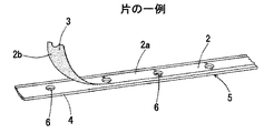
まず、綴じ装置1Aでの処理の対象となる片及びシート束について説明すると、第1の実施の形態の綴じ装置1Aは、図3に示すように、複数枚のシートが積層されたシート束10に片2を巻き付けることで、シート束10を綴じる装置である。シート束10は、書類等の用紙や、金属材料または樹脂材料等で形成されたシート状部材等を積層したものである。
First, a description will be given of a piece and a sheet bundle to be processed in the binding apparatus 1A. As shown in FIG. 3, the binding apparatus 1A according to the first embodiment is a sheet bundle 10 in which a plurality of sheets are stacked. This is a device for binding the sheet bundle 10 by winding the piece 2 around the sheet. The sheet bundle 10 is obtained by stacking sheets such as documents, sheet-like members formed of a metal material, a resin material, or the like.
片2は、一方の側がシート束10の一の面である下面から、シート束10の端部10a側に巻かれる。また、片2は、他方の側がシート束10に形成された貫通孔10bを通して巻かれる。そして、片2は、それぞれの端部側がシート束10の他の面である上面に貼り付けられる形態でシート束10を綴じる。
The piece 2 is wound from the lower surface, one side of which is one surface of the sheet bundle 10, to the end 10 a side of the sheet bundle 10. The piece 2 is wound through a through hole 10b formed on the sheet bundle 10 on the other side. And the piece 2 binds the sheet | seat bundle 10 in the form affixed on the upper surface which each edge part side is the other surface of the sheet | seat bundle 10. FIG.
片2は、図4に示すように、例えば矩形状に形成されており、一方の面2aを平面とし、他方の面2bに粘着層3が設けられ、例えば、長尺な剥離紙4に、長手方向に複数個仮着されている。これにより、片2は、長期間待機された後に使用される場合であっても、粘着層3の粘着力の低下を防止することができる。
As shown in FIG. 4, the piece 2 is formed in, for example, a rectangular shape, and one surface 2 a is a flat surface, and an adhesive layer 3 is provided on the other surface 2 b. For example, on the long release paper 4, A plurality are temporarily attached in the longitudinal direction. Thereby, even if it is a case where the piece 2 is used after having waited for a long period of time, the fall of the adhesive force of the adhesion layer 3 can be prevented.
更に、片2及び剥離紙4で構成されるテープ5は、例えば、ロール状に巻回されロール体となって、綴じ装置1Aに収納される。片2及び剥離紙4には、テープ5を送り出す機構が係合される係合孔6が、長手方向に所定の間隔を開けて複数個形成されている。
Furthermore, the tape 5 composed of the piece 2 and the release paper 4 is wound into a roll shape to form a roll body and is stored in the binding device 1A. In the piece 2 and the release paper 4, a plurality of engagement holes 6 with which a mechanism for feeding the tape 5 is engaged are formed at predetermined intervals in the longitudinal direction.
次に、綴じ装置1Aの構成について説明する。綴じ装置1Aは、シート束10を移動させることによるシート束10と片2との相対移動で、片2を予備整形する構成で、図1及び図2に示すように、ベース部11と、ベース部11に対して回転可能に設けられるハンドル部12を備える。また、綴じ装置1Aは、綴じ対象のシート束10を挟持して移動する挟持部20と、挟持部20との協働で片2を整形して、片2でシート束10を綴じる綴じ部40と、挟持部20との協働でテープ5を送る片送り部の一例としての送り部50を備える。
Next, the configuration of the binding device 1A will be described. The binding device 1A has a configuration in which the piece 2 is preliminarily shaped by the relative movement of the sheet bundle 10 and the piece 2 by moving the sheet bundle 10, and as shown in FIGS. The handle part 12 provided rotatably with respect to the part 11 is provided. In addition, the binding device 1 </ b> A shapes the piece 2 in cooperation with the holding unit 20 that moves while holding the sheet bundle 10 to be bound, and the binding unit 40 that binds the sheet bundle 10 with the piece 2. And a feeding unit 50 as an example of a one-feed unit that feeds the tape 5 in cooperation with the sandwiching unit 20.
ハンドル部12は操作部材の一例で、ベース部11の一方の端部側に設けられた軸支持部11mに、ハンドル部12の一方の端部側に設けられた軸12mが係合される。これにより、ハンドル部12は、一方の端部側が軸12mを支点として回転可能にベース部11に取り付けられ、他方の端部側が自由端となる。
The handle portion 12 is an example of an operation member, and a shaft 12 m provided on one end side of the handle portion 12 is engaged with a shaft support portion 11 m provided on one end side of the base portion 11. Thereby, the handle | steering-wheel part 12 is attached to the base part 11 so that one edge part side can rotate centering on the axis | shaft 12m, and the other edge part side turns into a free end.
綴じ装置1Aは、ハンドル部12の自由端側が操作されることで、ハンドル部12が軸12mを支点に回転し、このハンドル部12が回転する動作が、後述するように綴じ部40に伝達されて、綴じ部40が作動する。
In the binding apparatus 1A, when the free end side of the handle portion 12 is operated, the handle portion 12 rotates about the shaft 12m, and the operation of rotating the handle portion 12 is transmitted to the binding portion 40 as described later. Thus, the binding unit 40 operates.
ここで、綴じ装置1Aは、机等に載置して使用する形態が想定され、以下の説明では、ベース部11が設けられる側を、下面、下側、下方等、上下方向の下と定義し、ハンドル部12が設けられる側を、上面、上側、上方等、上下方向の上と定義する。また、ハンドル部12の自由端側を、前面、前側、前方等、前後方向の前と定義し、軸12mが設けられる側を、後面、後ろ側、後方等、前後方向の後と定義する。
Here, the binding device 1A is assumed to be used by being placed on a desk or the like. In the following description, the side on which the base portion 11 is provided is defined as the lower side, the lower side, the lower side, and the like in the vertical direction. The side on which the handle portion 12 is provided is defined as the upper side in the vertical direction such as the upper surface, the upper side, and the upper side. Further, the free end side of the handle portion 12 is defined as the front in the front-rear direction such as the front surface, the front side, and the front, and the side on which the shaft 12m is provided is defined as the rear in the front-rear direction such as the rear surface, the rear side, and the rear.
ベース部11は、挟持部20を移動可能に支持する移動支持部11nと、テープ5のロール体7が収納されたカセット8が着脱可能に装着されるカセット収納部11pを備える。
The base portion 11 includes a movement support portion 11n that movably supports the holding portion 20, and a cassette storage portion 11p in which a cassette 8 in which the roll body 7 of the tape 5 is stored is detachably mounted.
移動支持部11nは、ハンドル部12の自由端側と対向してベース部11の前方上面側に設けられ、矢印F及び矢印R方向への挟持部20の移動をガイドする前後方向に沿って設けられた溝部で構成される。カセット収納部11pは、ベース部11の後方側に、本例ではハンドル部12の軸12mの位置に合わせて設けられる。
11 n of movement support parts are provided in the front upper surface side of the base part 11 facing the free end side of the handle | steering-wheel part 12, and are provided along the front-back direction which guides the movement of the clamping part 20 to the arrow F and arrow R direction. It is comprised by the groove part made. The cassette housing portion 11p is provided on the rear side of the base portion 11 in accordance with the position of the shaft 12m of the handle portion 12 in this example.
次に、挟持部20について説明する。挟持部20は載置手段の一例で、ベース部11の前方上面に、移動支持部11nによって前後方向へ移動可能に取り付けられ、ハンドル部12の自由端側の下方に位置するシート束10の挿抜位置と、綴じ部40の下方に位置する綴じ位置との間を移動可能に構成される。
Next, the clamping part 20 is demonstrated. The clamping unit 20 is an example of a mounting unit, and is attached to the front upper surface of the base unit 11 so as to be movable in the front-rear direction by the movement support unit 11n, and the sheet bundle 10 positioned below the free end side of the handle unit 12 is inserted and removed It is configured to be movable between the position and the binding position located below the binding unit 40.
挟持部20は、綴じ対象物であるシート束10が載置されるトレイ23と、トレイ23に対して回転可能に取り付けられ、回転動作でシート束10をトレイ23に押さえ付ける押さえ部材24を備える。
The clamping unit 20 includes a tray 23 on which the sheet bundle 10 that is a binding target is placed, and a pressing member 24 that is rotatably attached to the tray 23 and presses the sheet bundle 10 against the tray 23 by a rotating operation. .
尚、挟持部20は、後述するように、シート束10に片2を1周巻き付ける動作の一部の予備整形に関わることから、予備整形手段を構成する。また、挟持部20は、テープ5を送る動作の一部に関わることから、搬送手段を構成する。
As will be described later, the clamping unit 20 is related to a part of preliminary shaping of the operation of winding the piece 2 around the sheet bundle 10 once, and thus constitutes a preliminary shaping means. Moreover, since the clamping part 20 is concerned with a part of operation | movement which sends the tape 5, it comprises a conveyance means.
トレイ23は、ベース部11の形状に合わせて本例では矩形平板状の形状で構成され、シート束10が載置される載置部23aと、ベース部11の移動支持部11nに係合される係合ガイド部23bを備える。係合ガイド部23bは、載置部23aの下面から下方に突出する形状で、ベース部11の移動支持部11nに係合される。これにより、挟持部20は、係合ガイド部23bが移動支持部11nにガイドされて、挿抜位置と綴じ位置との間の移動が可能となる。
The tray 23 is configured in a rectangular flat plate shape in this example according to the shape of the base portion 11, and is engaged with the placement portion 23 a on which the sheet bundle 10 is placed and the movement support portion 11 n of the base portion 11. The engagement guide part 23b is provided. The engagement guide portion 23b is engaged with the movement support portion 11n of the base portion 11 in a shape protruding downward from the lower surface of the placement portion 23a. Thereby, the clamping part 20 can move between the insertion / extraction position and the binding position by the engagement guide part 23b being guided by the movement support part 11n.
また、挟持部20は、載置部23aの後方側の端部に、押さえ部材24を回転可能に支持する回転軸23cが設けられる。更に、載置部23aの後端側には、幅方向略中央に、矩形状をなす切欠部23dが設けられている。切欠部23dは、挟持部20が綴じ位置に移動すると、シート束10を綴じる片2及び綴じ部40の後述する抜き刃44等が侵入可能な開口を、片2の貼着位置を避けて載置部23aに設けて構成される。
In addition, the clamping unit 20 is provided with a rotation shaft 23c that rotatably supports the pressing member 24 at an end on the rear side of the placement unit 23a. Furthermore, a rectangular cutout 23d is provided on the rear end side of the mounting portion 23a at the approximate center in the width direction. The notch portion 23d is provided with an opening through which a piece 2 for binding the sheet bundle 10 and a later-described punching blade 44 of the binding portion 40 can enter when the clamping portion 20 moves to the binding position, avoiding the sticking position of the piece 2. It is provided in the placement unit 23a.
挟持部20は、剥離紙4を保持する保持爪23eを備える。保持爪23eは搬送手段の一例で、剥離紙4の搬送経路に対向して係合ガイド部23bに設けられ、挟持部20の移動で矢印F及び矢印R方向に移動する。保持爪23eは、剥離紙4が引き出される搬送方向において、上流側に設けられた軸23fを支点とした回転動作で回転可能に構成され、バネ23gで剥離紙4方向に付勢される。
The clamping unit 20 includes a holding claw 23 e that holds the release paper 4. The holding claw 23e is an example of a conveyance unit, and is provided in the engagement guide portion 23b so as to face the conveyance path of the release paper 4 and moves in the directions of arrows F and R by the movement of the clamping unit 20. The holding claw 23e is configured to be rotatable by a rotation operation with a shaft 23f provided on the upstream side as a fulcrum in the transport direction in which the release paper 4 is drawn, and is biased in the direction of the release paper 4 by a spring 23g.
保持爪23eは、挟持部20を挿抜位置から綴じ位置に移動させる動作で矢印R方向に移動すると、バネ23gに抗して軸23fを支点に矢印G1方向に回転し、剥離紙4の搬送経路から退避する。これにより、剥離紙4の係合孔6とは係合せず、挟持部20を挿抜位置から綴じ位置に移動させる動作で、テープ5及び剥離紙4が逆送りされない。
Retaining claws 23e, when the clamping portion 20 moves from the insertion position in the direction of arrow R in operation to move to the binding position, and rotating the shaft 23f as a fulcrum in an arrow G 1 direction against the spring 23g, conveyance of release paper 4 Evacuate from the route. Thereby, the tape 5 and the release paper 4 are not fed back by the operation of moving the holding part 20 from the insertion / extraction position to the binding position without engaging with the engagement hole 6 of the release paper 4.
一方、保持爪23eは、挟持部20を綴じ位置から挿抜位置に移動させる動作で矢印F方向に移動すると、バネ23gの力で軸23fを支点に矢印G2方向に回転し、剥離紙4の搬送経路に突出する。これにより、保持爪23eが剥離紙4の係合孔6と係合し、挟持部20を綴じ位置から挿抜位置に移動させる動作で、テープ5及び剥離紙4が引き出される。
On the other hand, the holding claws 23e, moving from the position stapling the clamping portion 20 in the direction of arrow F in operation to move the insertion position, and rotating the shaft 23f as a fulcrum in an arrow G 2 direction by the force of the spring 23g, the release paper 4 Projects into the transport path. Thereby, the holding claw 23e engages with the engagement hole 6 of the release paper 4, and the tape 5 and the release paper 4 are pulled out by the operation of moving the holding portion 20 from the binding position to the insertion / extraction position.
押さえ部材24は、後端側が回転軸23cにより回転可能に支持され、トレイ23に対して矢印H1及び矢印H2方向に回転して、トレイ23の前方側を開閉する。押さえ部材24は弾性を有する材質で構成され、前方側を基端とした弾性片24bが一体で設けられる。
The pressing member 24 is rotatably supported at the rear end side by the rotation shaft 23 c, and rotates in the directions of arrows H 1 and H 2 with respect to the tray 23 to open and close the front side of the tray 23. The pressing member 24 is made of a material having elasticity, and is integrally provided with an elastic piece 24b whose front end is the base end.
弾性片24bは、載置部23aの切欠部23dの左右両側に位置するように、押さえ部材24から2本の部材が突出する形態で設けられ、後端側が自由端となってトレイ23側に折曲している。そして、弾性片24bは、後端がトレイ23に当接し、押さえ部材24の全体を持ち上げた状態として保持する。
The elastic pieces 24b are provided in a form in which two members protrude from the pressing member 24 so as to be located on both the left and right sides of the notch portion 23d of the mounting portion 23a, and the rear end side is a free end on the tray 23 side. It is bent. The elastic piece 24b is held in a state where the rear end abuts on the tray 23 and the entire pressing member 24 is lifted.
尚、挟持部20を構成するトレイ23及び押さえ部材24について、押さえ部材24を設けた意図は、シート束10の綴じ位置がトレイ23からずれないようにするためであって、綴じ動作の際に、シート束1の綴じ位置がトレイ23からずれないようなっていれば、必ずしも押さえ部材24を設ける必要はない。
The tray 23 and the pressing member 24 constituting the clamping unit 20 are provided with the intention of providing the pressing member 24 so that the binding position of the sheet bundle 10 does not deviate from the tray 23. If the binding position of the sheet bundle 1 does not deviate from the tray 23, the pressing member 24 is not necessarily provided.
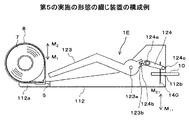
図5は、抜き刃の駆動機構を示す斜視図で、次に、各図を参照して、ハンドル部12の操作で綴じ部40及び抜き刃44を動作させる機構について説明する。
FIG. 5 is a perspective view showing the driving mechanism of the punching blade. Next, a mechanism for operating the binding portion 40 and the punching blade 44 by operating the handle portion 12 will be described with reference to each drawing.
綴じ部40は、ハンドル部12の内側下面に設けられる駆動部材41を備える。また、綴じ部40は、駆動部材41の変位で上下方向に移動するガイドレバー42と、シート束10を綴じる片2を押圧する押圧レバー43と、シート束10を貫通する抜き刃44を部品配設部27に備える。
The binding portion 40 includes a driving member 41 provided on the inner lower surface of the handle portion 12. In addition, the binding unit 40 includes a guide lever 42 that moves up and down by the displacement of the driving member 41, a pressing lever 43 that presses the piece 2 that binds the sheet bundle 10, and a punching blade 44 that penetrates the sheet bundle 10. It is provided in the installation part 27.
部品配設部27は、ベース部11と一体的に設けられ、挟持部20の移動経路に、綴じ位置へ移動する挟持部20が進入する進入溝28が設けられる。また、部品配設部27とベース部11は、剥離紙4から剥離された片2を待機させる片待機部28aが、進入溝28に挿入される挟持部20で挟持されたシート束10の移動経路に設けられる。進入溝28は、ベース部11と部品配設部27との間に離間して設けられた開口であり、挟持部20が進入することで、押さえ部材24をトレイ23に対して近接する矢印H1方向に押圧し、シート束10をトレイ23と押さえ部材24との間で挟持して保持する。挟持部20と進入溝28及び押圧レバー43は、挟持部20を移動させることによるシート束10と片2との相対移動で、片2を予備整形する予備整形手段を構成する。
The component arrangement part 27 is provided integrally with the base part 11, and an entry groove 28 into which the clamping part 20 that moves to the binding position enters is provided in the movement path of the clamping part 20. In addition, the component placement unit 27 and the base unit 11 move the sheet bundle 10 held by the holding unit 20 in which the piece standby unit 28 a that waits for the piece 2 peeled from the release paper 4 is inserted into the entry groove 28. Provided in the route. The entry groove 28 is an opening that is spaced apart between the base portion 11 and the component placement portion 27, and an arrow H that brings the pressing member 24 close to the tray 23 when the clamping portion 20 enters. By pressing in one direction, the sheet bundle 10 is sandwiched and held between the tray 23 and the pressing member 24. The sandwiching part 20, the entry groove 28 and the pressing lever 43 constitute a pre-shaping means for pre-shaping the piece 2 by relative movement of the sheet bundle 10 and the piece 2 by moving the sandwiching part 20.
綴じ部40は、押圧レバー43と抜き刃44が、進入溝28の上方に設けられ、ハンドル部12の動きを抜き刃44及びガイドレバー42を介して押圧レバー43に伝達する駆動部材41に第1のガイド孔41aと第2のガイド孔41bを備える。第1のガイド孔41aは、長孔に形成され、ガイドレバー42の凸部42aが係合される。第2のガイド孔41bは、長孔に形成され、抜き刃44が取り付けられた図5に示す取付部材49の凸部49aが係合される。
In the binding portion 40, the pressing lever 43 and the punching blade 44 are provided above the entry groove 28, and the binding member 40 is connected to the driving member 41 that transmits the movement of the handle portion 12 to the pressing lever 43 via the punching blade 44 and the guide lever 42. The first guide hole 41a and the second guide hole 41b are provided. The 1st guide hole 41a is formed in a long hole, and the convex part 42a of the guide lever 42 is engaged. The second guide hole 41b is formed in a long hole, the convex portion 49a of the mounting member 49 is engaged as shown in FIG. 5 where the punching blades 44 attached.
ハンドル部12の自由端側が操作されることで、ハンドル部12が軸12mを支点に回転すると、駆動部材41の第1のガイド孔41a及び第2のガイド孔41bの位置が上下方向に変位する。これにより、ハンドル部12が回転する動作で、ガイドレバー42を上下方向に直線移動させる。また、抜き刃44を上下方向に直線移動させる。
By operating the free end side of the handle portion 12, when the handle portion 12 rotates about the shaft 12m, the positions of the first guide hole 41a and the second guide hole 41b of the drive member 41 are displaced in the vertical direction. . Thereby, the guide lever 42 is linearly moved in the vertical direction by the operation of rotating the handle portion 12. Further, the punching blade 44 is linearly moved in the vertical direction.
ガイドレバー42は、部品配設部27にガイドされて、上下方向に移動可能に設けられる。ガイドレバー42には、コイルバネ45等の弾性部材が巻挿される。コイルバネ45は、ハンドル部12の所謂リターンバネを構成し、部品配設部27の受け部46により下端部がベース部11で受けられる。また、コイルバネ45は、駆動部材41の第1のガイド孔41aに係合されたガイドレバー42の凸部42aにより、上端部がハンドル部12で受けられる。
The guide lever 42 is guided by the component arrangement portion 27 and is provided to be movable in the vertical direction. An elastic member such as a coil spring 45 is wound around the guide lever 42. The coil spring 45 constitutes a so-called return spring of the handle portion 12, and the lower end portion is received by the base portion 11 by the receiving portion 46 of the component disposing portion 27. The upper end of the coil spring 45 is received by the handle portion 12 by the convex portion 42 a of the guide lever 42 engaged with the first guide hole 41 a of the drive member 41.
これにより、ハンドル部12は、コイルバネ45によって、ベース部11から離間する矢印U方向に付勢される。また、ハンドル部12が矢印D方向に押されることで、コイルバネ45が収縮すると共に、ガイドレバー42が矢印D方向に直線移動する。ここで、第1のガイド孔41aを長穴形状とすることで、変位の軌跡が軸12mを中心とした円弧形状となる第1のガイド孔41aに沿って凸部42aが移動可能となり、凸部42aの変位の軌跡が円弧形状とならずにガイドレバー42が直線移動する。
As a result, the handle portion 12 is urged by the coil spring 45 in the direction of the arrow U away from the base portion 11. Further, when the handle portion 12 is pushed in the arrow D direction, the coil spring 45 contracts and the guide lever 42 linearly moves in the arrow D direction. Here, by forming the first guide hole 41a into a long hole shape, the convex portion 42a can move along the first guide hole 41a whose displacement locus is an arc shape centered on the axis 12m. The guide lever 42 moves linearly without the locus of displacement of the portion 42a having an arc shape.
押圧レバー43は、ガイドレバー42の前方側に設けられる。押圧レバー43は、シート束10に片2を押圧して貼着する押圧部43aを備える。押圧レバー43は、コイルバネ等の弾性体でなる押圧バネ47が巻挿されている。押圧バネ47は、一端が押圧部43aに係止され、他端がガイドレバー42と連動して移動する移動部材48に係止される。
The pressing lever 43 is provided on the front side of the guide lever 42. The pressing lever 43 includes a pressing portion 43 a that presses and sticks the piece 2 to the sheet bundle 10. A pressing spring 47 made of an elastic body such as a coil spring is wound around the pressing lever 43. One end of the pressing spring 47 is locked to the pressing portion 43 a, and the other end is locked to a moving member 48 that moves in conjunction with the guide lever 42.
抜き刃44は、押圧レバー43の前方側に設けられる。抜き刃44は、図5に示すように、刃部44aの上方近傍に、片2が挿通される挿通孔44bが形成される。抜き刃44は、取付部材49に取り付けられており、この取付部材49は、ガイドレバー42に接続されている。
The punching blade 44 is provided on the front side of the pressing lever 43. As shown in FIG. 5, the punching blade 44 has an insertion hole 44b through which the piece 2 is inserted in the vicinity of the upper portion of the blade portion 44a. The extraction blade 44 is attached to an attachment member 49, and this attachment member 49 is connected to the guide lever 42.
抜き刃44は、ハンドル部12が操作されていない待機位置にある状態では、先端の刃部44aが進入溝28から下方に突出せず、ハンドル部12が矢印U方向に押されると、押圧レバー43の押圧部43aに押圧されているシート束10に貫通するように、刃部44aの高さ及び移動量が設定されている。
In the state where the punching blade 44 is in the standby position where the handle portion 12 is not operated, the tip blade portion 44a does not protrude downward from the entry groove 28, and when the handle portion 12 is pushed in the arrow U direction, The height and movement amount of the blade portion 44a are set so as to penetrate the sheet bundle 10 pressed by the pressing portion 43a of 43.
抜き刃44は、図5に示すように、取付部材49の左右の側方に凸部49aが突出し、各凸部49aが、駆動部材41の第2のガイド孔41bに係合されている。ここで、第2のガイド孔41bを長穴形状とすることで、変位の軌跡が軸12mを中心とした円弧形状となる第2のガイド孔41bに沿って凸部49aが移動可能となり、凸部49aの変位の軌跡が円弧形状とならずに抜き刃44が直線移動する。
As shown in FIG. 5, the punching blade 44 has protrusions 49 a protruding from the left and right sides of the mounting member 49, and each protrusion 49 a is engaged with the second guide hole 41 b of the drive member 41. Here, by forming the second guide hole 41b into a long hole shape, the convex portion 49a can move along the second guide hole 41b in which the locus of displacement is an arc shape centered on the axis 12m. The punching blade 44 moves linearly without the locus of displacement of the portion 49a having an arc shape.
以上のような綴じ部40は、ハンドル部12が矢印D方向に押し下げられると、ハンドル部12の軸12mを支点とした矢印D方向への回転動作で、駆動部材41の第2のガイド孔41bによって抜き刃44を駆動する凸部49aが押圧され、抜き刃44が矢印D方向に移動する。これにより、抜き刃44がシート束10を貫通する動作が行われる。
When the handle portion 12 is pushed down in the direction of arrow D, the binding portion 40 as described above is rotated in the direction of arrow D about the shaft 12m of the handle portion 12 as a fulcrum, so that the second guide hole 41b of the drive member 41 is driven. As a result, the projection 49a that drives the punching blade 44 is pressed, and the punching blade 44 moves in the direction of arrow D. Thereby, the operation of the punching blade 44 penetrating the sheet bundle 10 is performed.
また、ハンドル部12が矢印U方向に押し上げられると、ハンドル部12の軸12mを支点とした矢印U方向への回転動作で、駆動部材41の第2のガイド孔41bによって抜き刃44を駆動する凸部49aが押し上げられ、抜き刃44が矢印U方向に移動する。これにより、シート束10に貫通した抜き刃44が引き抜かれる動作が行われる。この抜き刃44が引き抜かれる動作では、後述するように、抜き刃44で保持した片2が、抜き刃44と連なって、シート束10の表面側に引き抜かれる動作が行われる。
Further, when the handle portion 12 is pushed up in the arrow U direction, the punching blade 44 is driven by the second guide hole 41b of the drive member 41 by a rotation operation in the arrow U direction with the shaft 12m of the handle portion 12 as a fulcrum. The convex portion 49a is pushed up, and the punching blade 44 moves in the arrow U direction. As a result, the operation of pulling out the punching blade 44 penetrating the sheet bundle 10 is performed. In the operation of pulling out the punching blade 44, as will be described later, an operation is performed in which the piece 2 held by the punching blade 44 is connected to the punching blade 44 and pulled out to the surface side of the sheet bundle 10.
綴じ装置1Aにおいて、ハンドル部12の自由端側が、作業者の力を受ける力点P1となる。また、駆動部材41の第2のガイド孔41bと凸部49aの係合箇所が、ハンドル部12から抜き刃44に力を及ぼす作用点P2となる。更に、ハンドル部12の軸12mが、動作の支点P3となる。
In the binding device 1A, the free end side of the handle portion 12 is a force point P1 that receives the force of the operator. Further, the engagement point between the second guide hole 41 b of the drive member 41 and the convex portion 49 a becomes an action point P <b> 2 that exerts a force on the punching blade 44 from the handle portion 12. Further, the shaft 12m of the handle portion 12 serves as a fulcrum P3 for operation.
綴じ装置1Aでは、軸12mを支点とした回転動作で変位するハンドル部12を備えた構成とし、力点P1から支点P3までの距離をL1、作用点P2から支点P3までの距離をL2としたとき、L1>L2の関係を満たすように、各構成の配置が決定される。
The binding device 1A is configured to include a handle portion 12 that is displaced by a rotation operation with a shaft 12m as a fulcrum, and the distance from the force point P1 to the fulcrum P3 is L1, and the distance from the action point P2 to the fulcrum P3 is L2. , L1> L2 is determined so as to satisfy the relationship of L1> L2.
次に、綴じ部40の一部を構成する押圧ローラ56について説明する。押圧ローラ56は、抜き刃44の前方側に設けられる。押圧ローラ56は、コイルバネ57等の弾性部材によって下方に付勢され、挟持部20が綴じ位置と挿抜位置との間を移動する動作で、シート束10を綴じた片2を押圧する。
Next, the pressing roller 56 constituting a part of the binding unit 40 will be described. The pressing roller 56 is provided on the front side of the punching blade 44. The pressing roller 56 is urged downward by an elastic member such as a coil spring 57, and presses the piece 2 on which the sheet bundle 10 is bound by an operation in which the clamping unit 20 moves between the binding position and the insertion / extraction position.
次に、送り部50について説明する。送り部50は搬送手段の一例で、ベース部11に取り付けられ、挟持部20の動作で搬送される片2が剥離される前のテープ5及び片2が剥離された剥離紙4の搬送路51を構成する。
Next, the feeding unit 50 will be described. The feeding unit 50 is an example of a conveying unit, and is attached to the base unit 11. The feeding path 51 of the release paper 4 from which the tape 5 before the strip 2 transported by the operation of the clamping unit 20 is stripped and the strip 2 is stripped. Configure.
送り部50は、テープ5の搬送経路を第1の方向である上方に向ける第1のローラ52aと、第1のローラ52aの下流側で、テープ5の搬送経路を第2の方向である水平方向より下方に向ける第2のローラ52bを備え、屈曲した搬送経路を構成する。また、送り部50は、剥離紙4を保持する係止爪52cと、係止爪52cで保持された剥離紙4を退避させる退避部52dを備える。
The feeding unit 50 has a first roller 52a that directs the transport path of the tape 5 upward in the first direction, and a horizontal transport path of the tape 5 in the second direction on the downstream side of the first roller 52a. A second roller 52b directed downward from the direction is provided to constitute a bent conveyance path. In addition, the feeding unit 50 includes a locking claw 52c that holds the release paper 4 and a retracting unit 52d that retracts the release paper 4 held by the locking claw 52c.
送り部50は、第2のローラ52bで搬送経路を鋭角状に屈曲させることで、片2の剛性を利用してテープ5から片2を剥離させる剥離部52eを構成する。送り部50では、カセット収納部11pに収納されたカセット8から引き出されたテープ5が、第1のローラ52aにガイドされて上側に向けて搬送される。次いで、テープ5は、第2のローラ52bにガイドされて、鋭角状に折曲される。剥離紙4が剥離部52eで鋭角状に折曲されることで、剥離紙4に仮着されている片2のみが上方に直進し、片2は、折れ曲がることなく真っ直ぐな状態で、剥離紙4から半分程度剥離された状態となる。剥離紙4から剥離された片2は、図4に示す粘着層3を、挟持部20に挟まれて進入してくるシート束10側にして、シート束10を待ち受ける状態となる。第2のローラ52bより下流側の剥離紙4は、ベース部11の前方側へと搬送されて排出される。
The feeding part 50 forms a peeling part 52e that peels the piece 2 from the tape 5 by using the rigidity of the piece 2 by bending the conveyance path with an acute angle by the second roller 52b. In the feeding section 50, the tape 5 drawn from the cassette 8 stored in the cassette storage section 11p is guided upward by the first roller 52a and conveyed upward. Next, the tape 5 is guided by the second roller 52b and bent at an acute angle. When the release paper 4 is bent at an acute angle at the release portion 52e, only the piece 2 temporarily attached to the release paper 4 goes straight upward, and the piece 2 is straight and is not bent. It will be in the state which peeled from 4 to about half. The piece 2 peeled from the release paper 4 is in a state of waiting for the sheet bundle 10 with the adhesive layer 3 shown in FIG. 4 on the side of the sheet bundle 10 that is sandwiched by the sandwiching portion 20 and enters. The release paper 4 on the downstream side of the second roller 52b is conveyed to the front side of the base portion 11 and discharged.
係止爪52cは、第2のローラ52bの下流側に設けられ、前方に傾斜した形態で搬送路51に突出し、剥離紙4の係合孔6と係合する。退避部52dは、係止爪52cと対向する位置に、剥離紙4が入る空間を設けて構成される。
The locking claw 52 c is provided on the downstream side of the second roller 52 b, protrudes into the conveyance path 51 in a form inclined forward, and engages with the engagement hole 6 of the release paper 4. The retracting portion 52d is configured by providing a space for the release paper 4 in a position facing the locking claw 52c.
挟持部20を挿抜位置から綴じ位置に移動させることで、保持爪23eが矢印R方向に移動する動作で、テープ5及び剥離紙4に逆送りされる方向の力が加えられると、係止爪52cが剥離紙4の係合孔6と係合し、テープ5及び剥離紙4が逆送りされない。
When the holding claw 20 is moved from the insertion / extraction position to the binding position, the holding claw 23e is moved in the direction of the arrow R, and when a force in the direction reversely fed to the tape 5 and the release paper 4 is applied, the locking claw 52c engages with the engagement hole 6 of the release paper 4, and the tape 5 and the release paper 4 are not fed back.
一方、挟持部20を綴じ位置から挿抜位置に移動させることで、保持爪23eが矢印F方向に移動する動作で、テープ5及び剥離紙4に順送りされる方向の力が加えられると、剥離紙4の係合孔6が係止爪52cから外れ、剥離紙4が退避部52dに入り、テープ5及び剥離紙4の順方向への搬送が可能となる。剥離紙4を搬送する力が加わらなくなると、剥離紙4の係合孔6が係止爪52cに係合する。
On the other hand, when the force in the direction forwardly fed to the tape 5 and the release paper 4 is applied by moving the holding portion 20 from the binding position to the insertion / extraction position, the holding claw 23e moves in the direction of arrow F, the release paper The four engagement holes 6 are disengaged from the locking claws 52c, and the release paper 4 enters the retracting portion 52d, so that the tape 5 and the release paper 4 can be conveyed in the forward direction. When the force for conveying the release paper 4 is no longer applied, the engagement hole 6 of the release paper 4 engages with the locking claw 52c.
送り部50は、軸50aを支点とした回転動作でベース部11に対して開閉可能に構成され、第2のローラ52b及び係止爪52cが送り部50に設けられ、第1のローラ52aがベース部11に設けられる。これにより、送り部50をベース部11に対して開くことで、第2のローラ52b及び係止爪52cが搬送経路から退避して搬送路51が露出し、テープ5及び剥離紙4の着脱が容易に行える。
The feed portion 50 is configured to be openable and closable with respect to the base portion 11 by a rotational operation with the shaft 50a as a fulcrum, the second roller 52b and the locking claw 52c are provided in the feed portion 50, and the first roller 52a is Provided in the base portion 11. Thereby, by opening the feeding part 50 with respect to the base part 11, the second roller 52b and the locking claw 52c are retracted from the conveying path, the conveying path 51 is exposed, and the tape 5 and the release paper 4 can be attached and detached. Easy to do.
<第1の実施の形態の綴じ装置の動作例>
図6は、片でシート束を綴じる動作の概要を示す説明図、図7〜図12は、第1の実施の形態の綴じ装置の動作の一例を示す説明図であり、次に、各図を参照して、第1の実施の形態の綴じ装置1Aで片2によりシート束10を綴じる動作について説明する。
<Operation example of the binding device according to the first embodiment>
FIG. 6 is an explanatory diagram illustrating an outline of an operation of binding a sheet bundle with a piece, and FIGS. 7 to 12 are explanatory diagrams illustrating an example of an operation of the binding device according to the first embodiment. The operation of binding the sheet bundle 10 by the pieces 2 in the binding device 1A of the first embodiment will be described with reference to FIG.
図6(a)及び図7に示す待機状態では、ハンドル部12は操作されておらず、抜き刃44が進入溝28の上方の待機位置に退避している。また、挟持部20は、押さえ部材24が矢印H2方向に回転して、トレイ23に対して開いた状態となって、挿抜位置Pp1に位置する。
In the standby state shown in FIGS. 6A and 7, the handle portion 12 is not operated, and the punching blade 44 is retracted to the standby position above the entry groove 28. In addition, the clamping unit 20 is positioned at the insertion / extraction position Pp < b > 1 with the pressing member 24 rotating in the direction of arrow H < b > 2 and being open with respect to the tray 23.
更に、片2は、剥離紙4から半分程度剥離した部分が片待機部28aに突出し、図6(a)に示すように、挟持部20で挟持されて挿抜位置Pp1から綴じ位置Pp2へと移動するシート束10の移動経路で待機する。
Furthermore, as for the piece 2, the part which peeled about half from the release paper 4 protrudes in the piece standby part 28a, and as shown to Fig.6 (a), it is clamped by the clamping part 20 and moves from the insertion / extraction position Pp1 to the binding position Pp2. It waits in the movement path | route of the sheet bundle 10 to perform.
このような待機状態の綴じ装置1Aにおいて、シート束10がトレイ23の載置部23aに置かれると、押さえ部材24及び弾性片24bが、シート束10の厚さに応じて弾性変形し、弾性片24bによって載置部23aに仮押さえされる。
In such a standby binding device 1A, when the sheet bundle 10 is placed on the placement portion 23a of the tray 23, the pressing member 24 and the elastic piece 24b are elastically deformed according to the thickness of the sheet bundle 10, and elastically. The piece 24b is temporarily held by the placement portion 23a.
図8に示すシート束10の保持状態では、押さえ部材24が作業者により矢印H1方向に押されることで、押さえ部材24が回転軸23cを支点に矢印H1方向に回転し、押さえ部材24及び弾性片24bが更に弾性変形して、押さえ部材24とトレイ23間で、弾性片24bによってシート束10が保持される。
In the holding state of the sheet bundle 10 shown in FIG. 8, when the pressing member 24 is pressed in the direction of arrow H 1 by the operator, the pressing member 24 rotates in the direction of arrow H 1 with the rotation shaft 23c as a fulcrum. The elastic piece 24b is further elastically deformed, and the sheet bundle 10 is held between the pressing member 24 and the tray 23 by the elastic piece 24b.
図9に示す片2が予備整形される状態では、シート束10が保持された挟持部20が作業者により矢印Rに押されることにより、シート束10が保持された挟持部20が、挿抜位置Pp1から矢印R方向に移動して、片待機部28aで待機している片2にシート束10の端部10aが接する。シート束10が保持された挟持部20が更に矢印R方向に移動すると、シート束10及びシート束10に押された片2が、押圧レバー43の押圧部43aと進入溝28との間に挟まれる。
In the state in which the piece 2 shown in FIG. 9 is preliminarily shaped, when the operator presses the holding unit 20 holding the sheet bundle 10 in the direction of the arrow R, the holding unit 20 holding the sheet bundle 10 becomes the insertion / extraction position. The end portion 10a of the sheet bundle 10 is in contact with the piece 2 that is moved from Pp1 in the arrow R direction and is waiting at the piece standby portion 28a. When the clamping unit 20 holding the sheet bundle 10 further moves in the arrow R direction, the sheet bundle 10 and the piece 2 pressed by the sheet bundle 10 are sandwiched between the pressing portion 43a of the pressing lever 43 and the entry groove 28. It is.
そして、シート束10が保持された挟持部20が綴じ位置Pp2まで移動すると、図6(b)に示すように、押圧レバー43の押圧部43a及び進入溝28と、シート束10の端部10aとの組み合わせによる凹凸形状の間に片2が入る。これにより、片2は、シート束10の端部10aと、押圧レバー43の押圧部43a及び進入溝28の形状に合わせて予備整形されると共に、剥離紙4から剥離される。
When the clamping unit 20 holding the sheet bundle 10 moves to the binding position Pp2, as shown in FIG. 6B, the pressing portion 43a and the entrance groove 28 of the pressing lever 43 and the end portion 10a of the sheet bundle 10 are obtained. The piece 2 enters between the concavo-convex shape by the combination. As a result, the piece 2 is preliminarily shaped according to the shapes of the end portion 10 a of the sheet bundle 10, the pressing portion 43 a of the pressing lever 43, and the entry groove 28, and is peeled off from the release paper 4.
シート束10が保持された挟持部20が挿抜位置Pp1から綴じ位置Pp2まで移動する動作では、テープ5及び剥離紙4に逆送りされる方向の力が加えられ、係止爪52cが剥離紙4の係合孔6と係合する。また、保持爪23eがバネ23gに抗して軸23fを支点に矢印G1方向に回転し、剥離紙4の搬送経路から退避する。これにより、保持爪23eが剥離紙4の係合孔6とは係合せず、挟持部20を挿抜位置Pp1から綴じ位置Pp2に移動させる動作で、テープ5及び剥離紙4が逆送りされない。
In the operation in which the clamping unit 20 holding the sheet bundle 10 moves from the insertion / extraction position Pp1 to the binding position Pp2, a force in a direction reversely fed to the tape 5 and the release paper 4 is applied, and the locking claw 52c is released from the release paper 4. The engagement hole 6 is engaged. The holding claws 23e rotates the shaft 23f of the arrow G 1 direction as a fulcrum against the spring 23g, is retracted from the conveying path of the release paper 4. Thereby, the holding claw 23e does not engage with the engagement hole 6 of the release paper 4, and the tape 5 and the release paper 4 are not fed back by the operation of moving the holding part 20 from the insertion / extraction position Pp1 to the binding position Pp2.
図10に示すシート束10が抜き刃44で穿孔される状態では、ハンドル部12がコイルバネ45の付勢力に抗して矢印D方向に押し下げられると、ハンドル部12の軸12mを支点とした矢印D方向への回転動作で、駆動部材41の第1のガイド孔41aによってガイドレバー42の凸部42aが押圧され、ガイドレバー42が矢印D方向に移動する。
In the state where the sheet bundle 10 shown in FIG. 10 is punched by the punching blade 44, when the handle portion 12 is pushed down in the direction of arrow D against the urging force of the coil spring 45, an arrow with the shaft 12m of the handle portion 12 as a fulcrum By the rotation operation in the D direction, the convex portion 42a of the guide lever 42 is pressed by the first guide hole 41a of the drive member 41, and the guide lever 42 moves in the arrow D direction.
ガイドレバー42が矢印D方向に移動すると、ガイドレバー42で移動部材48が押圧され、押圧バネ47を介して押圧レバー43が押圧されて、押圧レバー43が矢印D方向に移動する。これにより、挟持部20で保持されて綴じ位置Pp2に移動したシート束10が、押圧レバー43の押圧部43aで押圧され、予備整形された片2において、押圧レバー43の押圧部43a及び進入溝28に挟まれる部位が、シート束10の表面及び裏面に貼着される。
When the guide lever 42 moves in the arrow D direction, the moving member 48 is pressed by the guide lever 42, the pressing lever 43 is pressed via the pressing spring 47, and the pressing lever 43 moves in the arrow D direction. As a result, the sheet bundle 10 held by the clamping unit 20 and moved to the binding position Pp2 is pressed by the pressing portion 43a of the pressing lever 43 and preliminarily shaped in the piece 2, and the pressing portion 43a of the pressing lever 43 and the entrance groove The part pinched by 28 is stuck on the front surface and the back surface of the sheet bundle 10.
また、ハンドル部12が矢印D方向に押し下げられると、ハンドル部12の軸12mを支点とした矢印D方向への回転動作で、駆動部材41の第2のガイド孔41bによって抜き刃44を駆動する凸部49aが押圧され、抜き刃44が矢印D方向に移動する。
When the handle portion 12 is pushed down in the arrow D direction, the punching blade 44 is driven by the second guide hole 41b of the drive member 41 by a rotation operation in the arrow D direction with the shaft 12m of the handle portion 12 as a fulcrum. The convex portion 49a is pressed, and the punching blade 44 moves in the arrow D direction.
そして、ハンドル部12が下死点に到達するまで押し下げられると、押圧レバー43でシート束10を押圧した状態で、図6(c)に示すように、抜き刃44がシート束10を貫通する。抜き刃44がシート束10を貫通すると、抜き刃44の挿通孔44bに、片2においてシート束10に貼着されていない部位であるシート束10の裏面側の自由端が進入する。
When the handle portion 12 is pushed down to reach the bottom dead center, the punching blade 44 penetrates the sheet bundle 10 as shown in FIG. . When the punching blade 44 penetrates the sheet bundle 10, the free end on the back surface side of the sheet bundle 10, which is a portion not attached to the sheet bundle 10 in the piece 2, enters the insertion hole 44 b of the punching blade 44.
図11に示す片2をシート束10に挿通させる状態では、ハンドル部12を押す力が弱まる等により、ハンドル部12を押圧する力が、コイルバネ45の復元力より弱くなると、復元しようとするコイルバネ45の力で、ガイドレバー42の凸部42aを介して駆動部材41の第1のガイド孔41aが押圧され、ハンドル部12が矢印U方向に押し上げられる。
In a state where the piece 2 shown in FIG. 11 is inserted through the sheet bundle 10, if the force pushing the handle portion 12 becomes weaker than the restoring force of the coil spring 45 due to weakening the force pushing the handle portion 12, the coil spring to be restored 45, the first guide hole 41a of the drive member 41 is pressed through the convex portion 42a of the guide lever 42, and the handle portion 12 is pushed up in the arrow U direction.
ハンドル部12の軸12mを支点とした矢印U方向への回転動作で、ガイドレバー42が矢印U方向に移動すると、押圧バネ47を介して押圧レバー43が押し上げられて、押圧レバー43が矢印U方向に移動し、シート束10の押圧が解放される。
When the guide lever 42 is moved in the arrow U direction by the rotation operation in the arrow U direction with the shaft 12m of the handle portion 12 as a fulcrum, the pressing lever 43 is pushed up via the pressing spring 47, and the pressing lever 43 is moved to the arrow U. The sheet bundle 10 is released from pressing.
また、ハンドル部12の軸12mを支点とした矢印U方向への回転動作で、駆動部材41の第2のガイド孔41bによって抜き刃44を駆動する凸部49aが押し上げられ、抜き刃44が矢印U方向に移動する。そして、図6(d)に示すように、抜き刃44の戻り動作、即ち、シート束10に貫通した抜き刃44が引き抜かれる動作で、挿通孔44bに挿通した片2の自由端が抜き刃44と連なって、シート束10の表面側に引き抜かれる。
Further, by the rotation operation in the arrow U direction with the shaft 12m of the handle portion 12 as a fulcrum, the convex portion 49a that drives the punching blade 44 is pushed up by the second guide hole 41b of the driving member 41, and the punching blade 44 is moved to the arrow. Move in the U direction. Then, as shown in FIG. 6D, the free end of the piece 2 inserted through the insertion hole 44b is returned by the return operation of the extraction blade 44, that is, the operation of extracting the extraction blade 44 penetrating the sheet bundle 10. The continuous sheet 44 is pulled out to the surface side of the sheet bundle 10.
図12に示す片2を本整形してシート束10を取り出す状態では、ハンドル部12が上死点まで押し上げられて待機位置まで戻った後、シート束10を保持している挟持部20を矢印F方向へ移動させる。挟持部20が綴じ位置Pp2から挿抜位置Pp1へ移動する動作で、図6(e)に示すように、シート束10を挿通した片2が、シート束10と押圧ローラ56との間に挟まれる。そして、片2が押圧ローラ56でシート束10に押圧されることで、片2は、シート束10に貼り付けられて本整形される。
In the state in which the piece 2 shown in FIG. 12 is fully shaped and the sheet bundle 10 is taken out, after the handle portion 12 is pushed up to the top dead center and returned to the standby position, the holding portion 20 holding the sheet bundle 10 is indicated by an arrow. Move in F direction. As shown in FIG. 6 (e), the movement of the holding unit 20 from the binding position Pp 2 to the insertion / extraction position Pp 1 causes the piece 2 inserted through the sheet bundle 10 to be sandwiched between the sheet bundle 10 and the pressing roller 56. . Then, when the piece 2 is pressed against the sheet bundle 10 by the pressing roller 56, the piece 2 is attached to the sheet bundle 10 and is fully shaped.
挟持部20が綴じ位置Pp2から挿抜位置Pp1まで移動する動作では、保持爪23eが矢印F方向に移動することで、バネ23gの力で軸23fを支点に矢印G2方向に回転し、剥離紙4の搬送経路に突出する。これにより、保持爪23eが剥離紙4の係合孔6と係合し、剥離紙4を矢印F方向に移動させる力が加えられる。剥離紙4を矢印F方向に移動させる力が加えられると、剥離紙4の係合孔6が係止爪52cから外れ、剥離紙4が退避部52dに入る。
In the operation clamping portion 20 moves from the binding position Pp2 to inserting and removing position Pp1, by holding claw 23e is moved in the direction of arrow F, and rotated in the arrow G 2 direction axis 23f to a fulcrum by the force of the spring 23g, release paper 4 protrudes into the transport path. Thereby, the holding claw 23e is engaged with the engagement hole 6 of the release paper 4, and a force for moving the release paper 4 in the arrow F direction is applied. When a force for moving the release paper 4 in the direction of arrow F is applied, the engagement hole 6 of the release paper 4 is disengaged from the locking claw 52c, and the release paper 4 enters the retracting portion 52d.
これにより、挟持部20を綴じ位置Pp2から挿抜位置Pp1に移動させる動作で、テープ5及び剥離紙4が、片2の1つ分の長さ引き出される。挟持部20が停止して、剥離紙4を移動させる力が加わらなくなると、剥離紙4の係合孔6が係止爪52cに係合する。テープ5及び剥離紙4が、片2の1つ分の長さ引き出されると、次の片2が、剥離紙4から半分程度剥離した部分が片待機部28aに突出する。
Thereby, the tape 5 and the release paper 4 are pulled out by the length of one piece 2 by the operation of moving the clamping unit 20 from the binding position Pp2 to the insertion / extraction position Pp1. When the clamping unit 20 stops and the force for moving the release paper 4 is no longer applied, the engagement hole 6 of the release paper 4 engages with the locking claw 52c. When the tape 5 and the release paper 4 are pulled out for the length of one of the pieces 2, a portion where the next piece 2 is peeled about half from the release paper 4 protrudes to the piece standby portion 28 a.
挟持部20を挿抜位置Pp1まで移動させた後、押さえ部材24を回転軸23cを支点に矢印H2方向に回転させ、押さえ部材24を開くことで、シート束10をトレイ23から取り出すことが可能となる。
After moving the clamping portion 20 to insertion position Pp1, rotated in the arrow H 2 direction pressing member 24 the rotating shaft 23c as the fulcrum, by opening the pressing member 24, can be taken out sheet bundle 10 from the tray 23 It becomes.
図13は、本実施の形態の綴じ装置の効果例を示す説明図である。従来の綴じ装置では、抜き刃44を駆動する綴じ部40は、抜き刃44の直上に設けられた一点鎖線で示す操作部材121の力を受ける。これにより、作業者の力を受ける力点P10と、操作部材121から抜き刃44に力を及ぼす作用点P20は略一致する。このため、抜き刃44でシート束10を貫通する際に操作部材121に掛かる荷重、及び、抜き刃44が片2と共にシート束10から抜ける際に操作部材121に掛かる荷重は低減されない。
FIG. 13 is an explanatory diagram illustrating an effect example of the binding device according to the present embodiment. In the conventional binding device, the binding portion 40 that drives the punching blade 44 receives the force of the operation member 121 indicated by a one-dot chain line provided immediately above the punching blade 44. As a result, the force point P10 that receives the force of the operator and the action point P20 that exerts a force on the punching blade 44 from the operating member 121 substantially coincide. For this reason, the load applied to the operation member 121 when penetrating the sheet bundle 10 with the punching blade 44 and the load applied to the operation member 121 when the punching blade 44 comes out of the sheet bundle 10 together with the piece 2 are not reduced.
これに対し、綴じ装置1Aでは、作業者の力を受ける力点P1と支点P3との間に、ハンドル部12から抜き刃44に力を及ぼす作用点P2が設けられることで、力点P1から支点P3までの距離L1が、作用点P2から支点P3までの距離L2より長く構成される。
On the other hand, in the binding device 1A, an action point P2 that exerts a force on the punching blade 44 from the handle portion 12 is provided between the force point P1 that receives the operator's force and the fulcrum P3, so that the force point P1 to the fulcrum P3. Is configured to be longer than the distance L2 from the action point P2 to the fulcrum P3.
これにより、抜き刃44がシート束10を貫通する動作でハンドル部12の力点P1に掛かる操作荷重、及び、抜き刃44が片2と共にシート束10から抜ける動作でハンドル部12の力点P1に掛かる操作荷重が、抜き刃44の直上に操作部材121がある場合と比較して低減される。また、ハンドル部12の最大高さHは、従来の操作部材121の高さと同等にすることができ、装置の大型化を防ぐことができる。
Accordingly, the operation load applied to the power point P1 of the handle portion 12 when the punching blade 44 penetrates the sheet bundle 10 and the force point P1 of the handle portion 12 applied to the punching blade 44 when the punching blade 44 is removed from the sheet bundle 10 together with the piece 2. The operation load is reduced compared to the case where the operation member 121 is directly above the punching blade 44. Moreover, the maximum height H of the handle part 12 can be made equal to the height of the conventional operation member 121, and the enlargement of the apparatus can be prevented.
抜き刃44がシート束10を貫通する動作でハンドル部12の力点P1に掛かる操作荷重が低減されることで、抜き刃44をシート束10に確実に貫通させることができる。また、抜き刃44が片2と共にシート束10から抜ける動作でハンドル部12の力点P1に掛かる操作荷重が低減されることで、片2を確実にシート束10に挿通させることができる。これにより、綴じ不良の発生を抑制することができる。
The operation load applied to the force point P1 of the handle portion 12 by the operation of the punching blade 44 penetrating the sheet bundle 10 is reduced, so that the punching blade 44 can be reliably penetrated through the sheet bundle 10. In addition, the operation load applied to the force point P1 of the handle portion 12 by the operation of the punching blade 44 withdrawing from the sheet bundle 10 together with the piece 2 is reduced, so that the piece 2 can be reliably inserted into the sheet bundle 10. Thereby, generation | occurrence | production of a binding defect can be suppressed.
なお、操作部材が戻る方向に付勢する弾性部材を弱いものとすれば、従来構成でも操作荷重を低減することはできるが、シート束に片を挿通させる動作で、弾性部材の復元力が弱いと、確実に片を挿通させることができず、綴じ不良が発生する可能性が増える。本実施の形態では、ハンドル部12を戻る方向に付勢するコイルバネ45を必要以上に弱くしなくても、操作荷重を低減することができ、シート束10に片2を挿通させる動作で、確実に片2を挿通させることができる。
If the elastic member that biases the operation member in the returning direction is weak, the operation load can be reduced even in the conventional configuration, but the restoring force of the elastic member is weak in the operation of inserting the piece into the sheet bundle. In this case, the pieces cannot be surely inserted, and the possibility that a binding failure occurs increases. In the present embodiment, the operation load can be reduced without making the coil spring 45 that urges the handle portion 12 in the returning direction unnecessarily weak, and the operation of inserting the piece 2 into the sheet bundle 10 is reliable. The piece 2 can be inserted into
また、モータ等による駆動機構を備えることなく、軽い操作荷重で操作可能であり、装置の大型化、高コスト化を防ぎ、安価で小型の装置を提供できる。
Further, it is possible to operate with a light operation load without providing a drive mechanism such as a motor, and to prevent an increase in size and cost of the device, and to provide an inexpensive and small device.
<第2の実施の形態の綴じ装置の構成例>
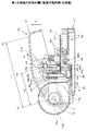
図14及び図15は、第2の実施の形態の綴じ装置の一例を示す構成図である。ここで、図14は、綴じ装置1Bの内部構成を示し、図15は、綴じ装置1Bの外観構成を示す。第2の実施の形態の綴じ装置1Bは、シート束10を移動させることによるシート束10と片2との相対移動で、片2を予備整形する構成で、シート束10を移動させる挟持部20の動作を、ハンドル部12の操作と連動させる構成である。なお、第1の実施の形態の綴じ装置1Aと同等の構成については、同じ番号を付して詳細な説明は省略する。
<Configuration example of the binding device according to the second embodiment>
14 and 15 are configuration diagrams illustrating an example of the binding device according to the second embodiment. Here, FIG. 14 shows an internal configuration of the binding device 1B, and FIG. 15 shows an external configuration of the binding device 1B. The binding device 1B according to the second embodiment has a configuration in which the sheet bundle 10 is moved by moving the sheet bundle 10 by the relative movement between the sheet bundle 10 and the piece 2 and the sheet bundle 10 is moved. This operation is linked to the operation of the handle portion 12. In addition, about the structure equivalent to 1 A of binding apparatuses of 1st Embodiment, the same number is attached | subjected and detailed description is abbreviate | omitted.
綴じ装置1Bは、ハンドル部12の動作を挟持部20へ伝達する移動操作部材25を備える。移動操作部材25は動作伝達手段の一例で、ベース部11の部品配設部27に回転軸34aを支点に回転可能に取り付けられる。移動操作部材25は、挟持部20のトレイ23に設けた回転軸23cに係合される駆動孔35を備える。駆動孔35は長穴形状で、この長孔形状に沿って回転軸23cが移動可能に係合される。また、移動操作部材25は、回動操作孔36を備える。回動操作孔36には、ハンドル12部の内側に設けられた接続突起37が係合される。
The binding device 1 </ b> B includes a movement operation member 25 that transmits the operation of the handle unit 12 to the holding unit 20. The movement operation member 25 is an example of a motion transmission means, and is attached to the component arrangement portion 27 of the base portion 11 so as to be rotatable about the rotation shaft 34a. The movement operation member 25 includes a drive hole 35 that is engaged with a rotation shaft 23 c provided on the tray 23 of the clamping unit 20. The drive hole 35 has a long hole shape, and the rotary shaft 23c is movably engaged along the long hole shape. The movement operation member 25 includes a rotation operation hole 36. A connection protrusion 37 provided inside the handle 12 is engaged with the rotation operation hole 36.
ハンドル部12が矢印D方向に押し下げられると、軸12mを支点とした矢印D方向への回転動作による接続突起37bの軌跡により、接続突起37が移動操作部材25の回動操作孔36を移動して、移動操作部材25を変位させる力が加えられる。
When the handle portion 12 is pushed down in the direction of arrow D, the connection projection 37 moves through the rotation operation hole 36 of the movement operation member 25 due to the locus of the connection projection 37b caused by the rotation in the direction of arrow D about the shaft 12m. Thus, a force for displacing the moving operation member 25 is applied.
これにより、移動操作部材25は、回転軸34aを支点に回転し、この回転動作に伴い、駆動孔35が矢印J1方向に移動する。駆動孔35が矢印J1方向に移動することで、駆動孔35に係合された回転軸23cが押圧され、ハンドル部12の操作による移動操作部材25の回転動作が、挟持部20の矢印R方向への直線移動に変換される。
Accordingly, the moving operation member 25 is rotated a rotation shaft 34a as a fulcrum, with this rotation, the drive holes 35 are moved in the arrow J 1 direction. When the drive hole 35 moves in the direction of the arrow J 1 , the rotation shaft 23 c engaged with the drive hole 35 is pressed, and the rotation operation of the moving operation member 25 by the operation of the handle portion 12 is performed. Converted to linear movement in the direction.
挟持部20が矢印R方向へ移動して進入溝28に進入することによって、押さえ部材24が押圧され、押さえ部材24が回転軸23cを支点に矢印H1方向に回転して、トレイ23に載置されたシート束10が、押さえ部材24とトレイ23との間に挟持されて保持される。
By entering the entry groove 28 clamping portion 20 is moved in the direction of arrow R, is pressed pressing member 24, the pressing member 24 is rotated in the arrow H 1 direction rotation shaft 23c as a fulcrum, the mounting tray 23 The placed sheet bundle 10 is sandwiched and held between the pressing member 24 and the tray 23.
ハンドル部12が矢印U方向に上げられると、軸12mを支点とした矢印U方向への回転動作による接続突起37bの軌跡により、接続突起37が移動操作部材25の回動操作孔36を移動して、移動操作部材25を変位させる力が加えられる。
When the handle portion 12 is raised in the direction of the arrow U, the connection projection 37 moves through the rotation operation hole 36 of the movement operation member 25 due to the locus of the connection projection 37b by the rotation operation in the direction of the arrow U about the shaft 12m. Thus, a force for displacing the moving operation member 25 is applied.
これにより、移動操作部材25は、回転軸34aを支点に回転し、この回転動作に伴い、駆動孔35が矢印J2方向に移動する。駆動孔35が矢印J2方向に移動することで、駆動孔35に係合された回転軸23cが押圧され、ハンドル部12の操作による移動操作部材25の回転動作が、挟持部20の矢印F方向への直線移動に変換される。
Accordingly, the moving operation member 25 is rotated a rotation shaft 34a as a fulcrum, with this rotation, the drive holes 35 are moved in the arrow J 2 direction. By driving hole 35 is moved in the arrow J 2 direction, engaged rotating shaft 23c is pressed against the driving hole 35, rotation of the movement operation member 25 by the operation of the handle portion 12, an arrow F of the clamping portion 20 Converted to linear movement in the direction.
挟持部20が矢印F方向へ移動して進入溝28から退避することによって、押さえ部材24が弾性片24bが復元する弾性力で回転軸23cを支点に矢印H2方向に回転して開き、トレイ23に載置されたシート束10が着脱可能となる。
By sandwiching portion 20 is retracted from the entry groove 28 is moved in the direction of arrow F, to open and rotated in the arrow H 2 direction rotation shaft 23c as the fulcrum by the elastic force of the pressing member 24 is restored the elastic piece 24b, tray The sheet bundle 10 placed on 23 can be attached and detached.
なお、綴じ装置1Bでは、ハンドル部12の操作を、ハンドル部12に設けられた接続突起37と係合された回動操作孔36、及び挟持部20に設けられた回転軸23cと係合する駆動孔35を有する移動操作部材25を介して挟持部20に伝達するカムとリンクを用いた機構を採用しているが、例えばピニオンギヤとラックとを組み合わせたり、歯車列を組み合わせたりすることで、ハンドル部12の操作を挟持部20に伝達する構成としても良い。
In the binding device 1B, the operation of the handle portion 12 is engaged with the rotation operation hole 36 engaged with the connection protrusion 37 provided on the handle portion 12 and the rotation shaft 23c provided on the holding portion 20. A mechanism using a cam and a link that transmits to the holding unit 20 via the moving operation member 25 having the drive hole 35 is adopted, but for example, by combining a pinion gear and a rack, or by combining a gear train, It is good also as a structure which transmits operation of the handle part 12 to the clamping part 20. FIG.
<第2の実施の形態の綴じ装置の動作例>
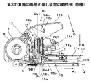
図16〜図19は、第2の実施の形態の綴じ装置の動作の一例を示す説明図であり、次に、各図を参照して、第2の実施の形態の綴じ装置1Bで片2によりシート束10を綴じる動作について、主にハンドル部12と挟持部20との連動する動作説明する。
<Operation example of the binding device according to the second embodiment>
16-19 is explanatory drawing which shows an example of operation | movement of the binding apparatus of 2nd Embodiment, Next, with reference to each figure, piece 2 with the binding apparatus 1B of 2nd Embodiment. Thus, the operation of binding the sheet bundle 10 will be described mainly in conjunction with the handle portion 12 and the clamping portion 20.
図16に示す待機状態では、ハンドル部12は操作されておらず、抜き刃44が進入溝28の上方の待機位置に退避している。また、挟持部20は、押さえ部材24が矢印H2方向に回転して、トレイ23に対して開いた状態となって、挿抜位置Pp1に位置する。
In the standby state shown in FIG. 16, the handle portion 12 is not operated, and the punching blade 44 is retracted to the standby position above the entry groove 28. In addition, the clamping unit 20 is positioned at the insertion / extraction position Pp < b > 1 with the pressing member 24 rotating in the direction of arrow H < b > 2 and being open with respect to the tray 23.
更に、片2は、剥離紙4から半分程度剥離した部分が片待機部28aに突出し、図6(a)に示すように、挟持部20で挟持されて挿抜位置Pp1から綴じ位置Pp2へと移動するシート束10の移動経路で待機する。
Furthermore, as for the piece 2, the part which peeled about half from the release paper 4 protrudes in the piece standby part 28a, and as shown to Fig.6 (a), it is clamped by the clamping part 20 and moves from the insertion / extraction position Pp1 to the binding position Pp2. It waits in the movement path | route of the sheet bundle 10 to perform.
このような待機状態の綴じ装置1Bにおいて、シート束10がトレイ23の載置部23aに置かれると、押さえ部材24及び弾性片24bが、シート束10の厚さに応じて弾性変形し、弾性片24bによって載置部23aに仮押さえされる。
In the binding device 1B in such a standby state, when the sheet bundle 10 is placed on the placement portion 23a of the tray 23, the pressing member 24 and the elastic piece 24b are elastically deformed according to the thickness of the sheet bundle 10 to be elastic. The piece 24b is temporarily held by the placement portion 23a.
図17に示すシート束10の保持状態及び片2が予備整形される状態では、ハンドル部12がコイルバネ45の付勢力に抗して矢印D方向に押し下げられると、ハンドル部12の軸12mを支点とした矢印D方向への回転動作による接続突起37bの軌跡により、接続突起37が移動操作部材25の回動操作孔36を移動して、移動操作部材25を変位させる力が加えられる。
In the holding state of the sheet bundle 10 shown in FIG. 17 and the state in which the piece 2 is pre-shaped, when the handle portion 12 is pushed down in the direction of arrow D against the biasing force of the coil spring 45, the shaft 12m of the handle portion 12 is supported as a fulcrum. Due to the locus of the connection protrusion 37b caused by the rotation operation in the arrow D direction, the connection protrusion 37 moves through the rotation operation hole 36 of the movement operation member 25, and a force for displacing the movement operation member 25 is applied.
これにより、移動操作部材25は、回転軸34aを支点に回転し、この回転動作に伴い、駆動孔35が矢印J1方向に移動する。駆動孔35が矢印J1方向に移動することで、駆動孔35に係合された回転軸23cが押圧され、挟持部20が挿抜位置Pp1から矢印R方向に移動する。
Accordingly, the moving operation member 25 is rotated a rotation shaft 34a as a fulcrum, with this rotation, the drive holes 35 are moved in the arrow J 1 direction. By driving hole 35 is moved in the arrow J 1 direction, it engaged rotating shaft 23c is pressed against the driving hole 35, clamping portions 20 moves from the insertion position Pp1 in the arrow R direction.
挟持部20が矢印R方向へ移動して進入溝28に進入することによって、押さえ部材24が押圧され、押さえ部材24が回転軸23cを支点に矢印H1方向に回転して、シート束10が挟持部20で保持される。
By entering the entry groove 28 clamping portion 20 is moved in the direction of arrow R, the pressing member 24 is pressed, the pressing member 24 is rotated in the arrow H 1 direction rotation shaft 23c as the fulcrum, the sheet bundle 10 It is held by the clamping unit 20.
そして、シート束10が保持された挟持部20が綴じ位置Pp2まで移動すると、図6(b)に示すように、押圧レバー43の押圧部43a及び進入溝28と、シート束10の端部10aとの組み合わせによる凹凸形状の間に片2が入る。これにより、片2は、シート束10の端部10aと、押圧レバー43の押圧部43a及び進入溝28の形状に合わせて予備整形される。また、予備整形された片2は、図14に示す剥離紙4から剥離される。
When the clamping unit 20 holding the sheet bundle 10 moves to the binding position Pp2, as shown in FIG. 6B, the pressing portion 43a and the entrance groove 28 of the pressing lever 43 and the end portion 10a of the sheet bundle 10 are obtained. The piece 2 enters between the concavo-convex shape by the combination. Thereby, the piece 2 is preliminarily shaped according to the shapes of the end portion 10 a of the sheet bundle 10, the pressing portion 43 a of the pressing lever 43, and the entry groove 28. Further, the pre-shaped piece 2 is peeled off from the release paper 4 shown in FIG.
シート束10が保持された挟持部20が挿抜位置Pp1から綴じ位置Pp2まで移動する動作では、第1の実施の形態の綴じ装置1Aの動作で説明した通り、テープ5及び剥離紙4が逆送りされない。
In the operation in which the clamping unit 20 holding the sheet bundle 10 moves from the insertion / extraction position Pp1 to the binding position Pp2, as described in the operation of the binding device 1A according to the first embodiment, the tape 5 and the release paper 4 are reversely fed. Not.
また、シート束10を保持する動作及び片2を予備整形する動作では、ハンドル部12の軸12mを支点とした矢印D方向への回転動作で、駆動部材41の第2のガイド孔41bによって抜き刃44を駆動する凸部49aが押圧され、抜き刃44が矢印D方向に移動するが、シート束10が綴じ位置Pp2に移動するタイミングでは、抜き刃44はシート束10に到達しない。
Further, in the operation of holding the sheet bundle 10 and the operation of preliminarily shaping the piece 2, it is extracted by the second guide hole 41 b of the drive member 41 by the rotation operation in the arrow D direction with the shaft 12 m of the handle portion 12 as a fulcrum. The convex portion 49a that drives the blade 44 is pressed and the extraction blade 44 moves in the direction of arrow D. However, the extraction blade 44 does not reach the sheet bundle 10 at the timing when the sheet bundle 10 moves to the binding position Pp2.
図18に示すシート束10が抜き刃44で穿孔される状態では、挟持部20で保持されて綴じ位置Pp2に移動したシート束10が押圧部43aで押圧され、予備整形された片2において、押圧部43a及び進入溝28に挟まれる部位が、シート束10の表面及び裏面に貼着される。
In the state in which the sheet bundle 10 shown in FIG. 18 is punched by the punching blade 44, the sheet bundle 10 held by the clamping unit 20 and moved to the binding position Pp2 is pressed by the pressing unit 43a and preliminarily shaped in the piece 2. Sites sandwiched between the pressing portion 43 a and the entry groove 28 are attached to the front and back surfaces of the sheet bundle 10.
ハンドル部12が下死点に到達するまで押し下げられると、図6(c)に示すように、抜き刃44がシート束10を貫通する。抜き刃44がシート束10を貫通すると、抜き刃44の図5に示す挿通孔44bに、片2においてシート束10に貼着されていない部位であるシート束10の裏面側の自由端が進入する。
When the handle portion 12 is pushed down until it reaches the bottom dead center, the punching blade 44 penetrates the sheet bundle 10 as shown in FIG. When the punching blade 44 penetrates the sheet bundle 10, the free end on the back surface side of the sheet bundle 10, which is a portion not attached to the sheet bundle 10 in the piece 2, enters the insertion hole 44 b shown in FIG. 5 of the punching blade 44. To do.
挟持部20が綴じ位置Pp2まで移動すると、移動操作部材25の回動操作孔36の形状により、接続突起37が回動操作孔36に沿って移動して、ハンドル部12の軸12mを支点とした矢印D方向への回転動作で、移動操作部材25は回転しない。これにより、シート束10を抜き刃44で穿孔する動作では、シート束10の位置は、綴じ位置Pp2で保持される。
When the clamping unit 20 moves to the binding position Pp2, the connection projection 37 moves along the rotation operation hole 36 due to the shape of the rotation operation hole 36 of the movement operation member 25, and the shaft 12m of the handle unit 12 is used as a fulcrum. The moving operation member 25 is not rotated by the rotation operation in the direction of the arrow D. Thereby, in the operation of punching the sheet bundle 10 with the punching blade 44, the position of the sheet bundle 10 is held at the binding position Pp2.
図19に示す片2をシート束10に挿通させる状態及び片2を本整形させるでは、ハンドル部12が矢印U方向に押し上げられると、ハンドル部12の軸12mを支点とした矢印U方向への回転動作で、駆動部材41の第2のガイド孔41bによって抜き刃44を駆動する凸部49aが押し上げられ、抜き刃44が矢印U方向に移動する。そして、図6(d)に示すように、抜き刃44の戻り動作、即ち、シート束10に貫通した抜き刃44が引き抜かれる動作で、挿通孔44bに挿通した片2の自由端が抜き刃44と連なって、シート束10の表面側に引き抜かれる。
In the state in which the piece 2 shown in FIG. 19 is inserted into the sheet bundle 10 and the shaping of the piece 2, when the handle portion 12 is pushed up in the arrow U direction, the handle portion 12 moves in the arrow U direction with the shaft 12 m as a fulcrum. In the rotation operation, the convex portion 49a that drives the punching blade 44 is pushed up by the second guide hole 41b of the driving member 41, and the punching blade 44 moves in the direction of the arrow U. Then, as shown in FIG. 6D, the free end of the piece 2 inserted through the insertion hole 44b is returned by the return operation of the extraction blade 44, that is, the operation of extracting the extraction blade 44 penetrating the sheet bundle 10. The continuous sheet 44 is pulled out to the surface side of the sheet bundle 10.
抜き刃44で片2をシート束10に挿通させる動作では、移動操作部材25の回動操作孔36の形状により、接続突起37が回動操作孔36に沿って移動して、ハンドル部12の軸12mを支点とした矢印U方向への回転動作で、移動操作部材25は回転しない。これにより、シート束10の位置は、綴じ位置Pp2で保持される。
In the operation of inserting the piece 2 into the sheet bundle 10 with the punching blade 44, the connection protrusion 37 moves along the rotation operation hole 36 due to the shape of the rotation operation hole 36 of the movement operation member 25, and The movement operation member 25 does not rotate by the rotation operation in the arrow U direction with the shaft 12m as a fulcrum. Thereby, the position of the sheet bundle 10 is held at the binding position Pp2.
ハンドル部12が更に矢印U方向に押し上げられると、軸12mを支点とした矢印U方向への回転動作による接続突起37bの軌跡により、接続突起37が移動操作部材25の回動操作孔36を移動して、移動操作部材25を変位させる力が加えられる。
When the handle portion 12 is further pushed up in the arrow U direction, the connection protrusion 37 moves through the rotation operation hole 36 of the movement operation member 25 due to the locus of the connection protrusion 37b by the rotation operation in the arrow U direction with the shaft 12m as a fulcrum. Then, a force for displacing the moving operation member 25 is applied.
これにより、移動操作部材25は、回転軸34aを支点に回転し、この回転動作に伴い、駆動孔35が矢印J2方向に移動する。駆動孔35が矢印J2方向に移動することで、駆動孔35に係合された回転軸23cが押圧され、挟持部20が綴じ位置Pp2から矢印F方向に移動する。
Accordingly, the moving operation member 25 is rotated a rotation shaft 34a as a fulcrum, with this rotation, the drive holes 35 are moved in the arrow J 2 direction. By driving hole 35 is moved in the arrow J 2 direction, it engaged rotating shaft 23c is pressed against the driving hole 35, clamping portions 20 moves from the binding position Pp2 in the arrow F direction.
挟持部20が綴じ位置Pp2から矢印F方向へ移動して、進入溝28から退避することにより、押さえ部材24が弾性片24bが復元する弾性力で回転軸23cを支点に矢印H2方向に回転して開き、ハンドル部12が上死点まで押し上げられて待機位置まで戻り、挟持部20が挿抜位置Pp1まで移動すると、トレイ23に載置されたシート束10が着脱可能となる。
Clamping portion 20 is moved from the binding position Pp2 direction of the arrow F rotation, by retracting the entry groove 28, the arrow H 2 direction rotation shaft 23c as the fulcrum by the elastic force of the pressing member 24 is restored the elastic piece 24b Then, when the handle portion 12 is pushed up to the top dead center and returned to the standby position, and the clamping portion 20 moves to the insertion / extraction position Pp1, the sheet bundle 10 placed on the tray 23 becomes detachable.
挟持部20が綴じ位置Pp2から挿抜位置Pp1へ移動する動作で、図6(e)に示すように、シート束10を挿通した片2が、シート束10と押圧ローラ56との間に挟まれる。そして、片2が押圧ローラ56でシート束10に押圧されることで、片2は、シート束10に貼り付けられて本整形される。
As shown in FIG. 6 (e), the movement of the holding unit 20 from the binding position Pp 2 to the insertion / extraction position Pp 1 causes the piece 2 inserted through the sheet bundle 10 to be sandwiched between the sheet bundle 10 and the pressing roller 56. . Then, when the piece 2 is pressed against the sheet bundle 10 by the pressing roller 56, the piece 2 is attached to the sheet bundle 10 and is fully shaped.
挟持部20が綴じ位置Pp2から挿抜位置Pp1まで移動する動作では、上述したように、テープ5及び剥離紙4が、片2の1つ分の長さ引き出され、次の片2が、剥離紙4から半分程度剥離した部分が片待機部28aに突出する。
In the operation in which the clamping unit 20 moves from the binding position Pp2 to the insertion / extraction position Pp1, as described above, the tape 5 and the release paper 4 are pulled out by the length of one piece 2, and the next piece 2 is the release paper. The part peeled from about 4 to half protrudes to the one standby part 28a.
綴じ装置1Bでは、挟持部20にシート束10を載置してからハンドル部12を回転操作することで、シート束10を挿抜位置Pp1から綴じ位置Pp2にまで引き込むことができ、操作性の向上を実現することができる。また、ハンドル部12の一連の回転操作の中で、挟持部20でシート束10を引き込み、片2で綴じる動作をすることができ、この点でも、操作性の向上を実現することができる。
In the binding device 1B, the sheet bundle 10 can be pulled from the insertion / extraction position Pp1 to the binding position Pp2 by rotating the handle portion 12 after the sheet bundle 10 is placed on the clamping unit 20, and the operability is improved. Can be realized. Further, during the series of rotation operations of the handle portion 12, the sheet bundle 10 can be pulled by the holding portion 20 and can be bound by the piece 2. In this respect, the operability can be improved.
更に、片2で綴じたシート束10を、ハンドル部12を戻す動作の中で綴じ位置Pp2から挿抜位置Pp1にまで移動させることができ、この点でも、操作性の向上を実現することができる。すなわち、綴じ装置1Bでは、ハンドル部12の一連の回転操作を行うことによって、挟持部20でシート束10を引き込み、片2でシート束10を綴じ、更に、挿抜位置Pp1までシート束10を戻して排出することができ、従来に比べ格段に操作性が向上する。
Further, the sheet bundle 10 bound by the pieces 2 can be moved from the binding position Pp2 to the insertion / extraction position Pp1 during the operation of returning the handle portion 12, and in this respect also, the operability can be improved. . That is, in the binding device 1B, by performing a series of rotation operations of the handle portion 12, the sheet bundle 10 is pulled in by the holding portion 20, the sheet bundle 10 is bound by the piece 2, and the sheet bundle 10 is returned to the insertion / extraction position Pp1. The operability is significantly improved compared to the conventional case.
綴じ装置1Bでも、作業者の力を受ける力点P1と支点P3との間に、ハンドル部12から抜き刃44に力を及ぼす作用点P2が設けられることで、力点P1から支点P3までの距離L1が、作用点P2から支点P3までの距離L2より長く構成される。
Also in the binding device 1B, the distance L1 from the force point P1 to the fulcrum P3 is provided between the force point P1 that receives the force of the operator and the fulcrum P3 by providing an action point P2 that exerts a force on the punching blade 44 from the handle portion 12. Is configured to be longer than the distance L2 from the action point P2 to the fulcrum P3.
これにより、抜き刃44がシート束10を貫通する動作でハンドル部12の力点P1に掛かる操作荷重、及び、抜き刃44が片2と共にシート束10から抜ける動作でハンドル部12の力点P1に掛かる操作荷重が、抜き刃44の直上に操作部材がある場合と比較して低減される。また、ハンドル部120の最大高さを、従来の操作部材と同等程度に抑えることができる。
Accordingly, the operation load applied to the power point P1 of the handle portion 12 when the punching blade 44 penetrates the sheet bundle 10 and the force point P1 of the handle portion 12 applied to the punching blade 44 when the punching blade 44 is removed from the sheet bundle 10 together with the piece 2. The operation load is reduced compared to the case where the operation member is directly above the punching blade 44. Further, the maximum height of the handle portion 120 can be suppressed to the same level as that of a conventional operation member.
更に、シート束10を抜き刃44で穿孔する動作では、移動操作部材25は回転せず、挟持部20は移動しない。これにより、挟持部20を移動させる際に掛かる荷重及びシート束10を予備整形する際に掛かる荷重は、シート束10を抜き刃44で穿孔するタイミングではハンドル部12に掛からない。
Further, in the operation of punching the sheet bundle 10 with the punching blade 44, the movement operation member 25 does not rotate and the clamping unit 20 does not move. Thereby, the load applied when moving the clamping unit 20 and the load applied when pre-shaping the sheet bundle 10 are not applied to the handle unit 12 at the timing when the sheet bundle 10 is punched by the extraction blade 44.
また、抜き刃44で片2をシート束10に挿通させる動作でも、移動操作部材25は回転せず、挟持部20は移動しない。これにより、挟持部20を移動させる際に掛かる荷重は、抜き刃44で片2をシート束10に挿通させるタイミングではハンドル部12に掛からない。
Even in the operation of inserting the piece 2 into the sheet bundle 10 with the punching blade 44, the moving operation member 25 does not rotate and the clamping unit 20 does not move. Thereby, the load applied when moving the clamping part 20 is not applied to the handle part 12 at the timing when the piece 2 is inserted into the sheet bundle 10 by the punching blade 44.
従って、ハンドル部12と挟持部20を連動させる構成としても、シート束10を抜き刃44で穿孔する動作、及び、抜き刃44で片2をシート束10に挿通させる動作では、ハンドル部12の力点P1に掛かる操作荷重が増加しない。
Therefore, even when the handle portion 12 and the sandwiching portion 20 are linked, in the operation of punching the sheet bundle 10 with the punching blade 44 and the operation of inserting the piece 2 into the sheet bundle 10 with the punching blade 44, The operation load applied to the power point P1 does not increase.
抜き刃44がシート束10を貫通する動作でハンドル部12の力点P1に掛かる操作荷重が低減されることで、抜き刃44をシート束10に確実に貫通させることができる。また、抜き刃44が片2と共にシート束10から抜ける動作でハンドル部12の力点P1に掛かる操作荷重が低減されることで、片2を確実にシート束10に挿通させることができる。これにより、綴じ不良の発生を抑制することができる。
The operation load applied to the force point P1 of the handle portion 12 by the operation of the punching blade 44 penetrating the sheet bundle 10 is reduced, so that the punching blade 44 can be reliably penetrated through the sheet bundle 10. In addition, the operation load applied to the force point P1 of the handle portion 12 by the operation of the punching blade 44 withdrawing from the sheet bundle 10 together with the piece 2 is reduced, so that the piece 2 can be reliably inserted into the sheet bundle 10. Thereby, generation | occurrence | production of a binding defect can be suppressed.
<第3の実施の形態の綴じ装置の構成例>
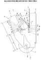
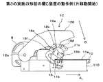
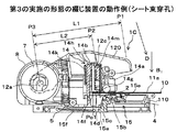
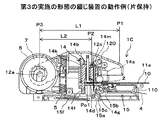
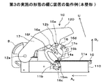
図20及び図21は、第3の実施の形態の綴じ装置の一例を示す構成図である。ここで、図20は、綴じ装置1Cの内部構成を示し、図21は、綴じ装置1Cの外観構成を示す。第3の実施の形態の綴じ装置1Cは、シート束10を移動させず、片2側を移動させることによるシート束10と片2との相対移動で、片2を予備整形する構成である。
<Configuration example of the binding device according to the third embodiment>
20 and 21 are configuration diagrams illustrating an example of the binding device according to the third embodiment. Here, FIG. 20 shows an internal configuration of the binding device 1C, and FIG. 21 shows an external configuration of the binding device 1C. The binding device 1C according to the third embodiment has a configuration in which the piece 2 is preliminarily shaped by relative movement between the sheet bundle 10 and the piece 2 by moving the piece 2 side without moving the sheet bundle 10.
綴じ装置1Cは、図20及び図21に示すように、ベース部110と、ベース部110に対して回転可能に設けられるハンドル部120を備える。また、綴じ装置1Cは、シート束10を押さえるシート束押さえ部13と、片2を整形してシート束10を綴じる綴じ部14と、テープ5を送る片送り部の一例としての送り部15を備える。更に、綴じ装置1Cは、ハンドル部120の動作を綴じ部14と送り部15に伝達する伝達部16を備える。
As illustrated in FIGS. 20 and 21, the binding device 1 </ b> C includes a base portion 110 and a handle portion 120 provided to be rotatable with respect to the base portion 110. The binding device 1C includes a sheet bundle pressing unit 13 that holds the sheet bundle 10, a binding unit 14 that shapes the pieces 2 and binds the sheet bundle 10, and a feeding unit 15 as an example of a single feeding unit that feeds the tape 5. Prepare. Furthermore, the binding device 1 </ b> C includes a transmission unit 16 that transmits the operation of the handle unit 120 to the binding unit 14 and the feeding unit 15.
ベース部110は、シート束10が載置される載置台11aと、シート束10の位置を片2による綴じ位置Po1に合わせる位置合わせ部11bと、綴じ部14を移動可能に支持する支持部11cを備える。また、ベース部110は、テープ5のロール体7が収納されたカセット8が着脱可能に装着される装着部11dを備える。
The base part 110 includes a placing table 11a on which the sheet bundle 10 is placed, a position aligning part 11b that aligns the position of the sheet bundle 10 with the binding position Po1 of the piece 2, and a support part 11c that supports the binding part 14 so as to be movable. Is provided. Moreover, the base part 110 is provided with the mounting part 11d by which the cassette 8 in which the roll body 7 of the tape 5 is accommodated is detachably mounted.
載置台11aは載置手段の一例で、シート束10の綴じ位置近傍の形状を平面状に保持して載置可能な略平面を、ベース部110の上面に設けて構成される。位置合わせ部11bは、載置台11aの上面に突出する形態で設けられ、シート束10の端部10aが位置合わせ部11bに突き当てられることで、シート束10の位置合わせが行われる。
The mounting table 11 a is an example of a mounting unit, and is configured by providing a substantially flat surface on the upper surface of the base portion 110 that can be mounted while holding the shape in the vicinity of the binding position of the sheet bundle 10 in a flat shape. The alignment unit 11b is provided in a form protruding from the upper surface of the mounting table 11a, and the end of the sheet bundle 10 is abutted against the alignment unit 11b, whereby the alignment of the sheet bundle 10 is performed.
支持部11cは、載置台11aの上面側に設けられ、綴じ部14の第1の移動方向として、載置台11aに沿った略水平方向である矢印A1及び矢印A2方向への綴じ部14の移動をガイドする溝部11eを備える。装着部11dは、ベース部110において載置台11aと反対側の一方の端部側に設けられ、載置台11aの下面側に、ロール体7から引き出されるテープ5を送る搬送経路が構成される。
Supporting unit 11c, the mounting provided on the upper surface side of the base 11a, the first as the moving direction, the arrow A 1 is a substantially horizontal direction along the mounting table 11a and an arrow A binding portion 14 in the two directions of the binding portion 14 The groove part 11e which guides the movement of is provided. 11 d of mounting parts are provided in the one end part side on the opposite side to the mounting base 11a in the base part 110, and the conveyance path | route which sends the tape 5 pulled out from the roll body 7 is comprised by the lower surface side of the mounting base 11a.
ハンドル部120は操作部材の一例で、一方の端部側が、軸12aを支点として回転可能にベース部110に取り付けられる。また、ハンドル部120は、軸12aを支点とした回転動作で変位する他方の端部側に、伝達部16と連結される連結軸部12bと、綴じ部14を押圧する押圧手段としての押圧部12cとを備える。
The handle portion 120 is an example of an operation member, and one end portion side is attached to the base portion 110 so as to be rotatable about the shaft 12a. The handle portion 120 includes a connecting shaft portion 12b connected to the transmission portion 16 and a pressing portion as pressing means for pressing the binding portion 14 on the other end portion side that is displaced by a rotation operation with the shaft 12a as a fulcrum. 12c.
シート束押さえ部13は、一方の端部側が、ハンドル部120と同軸で軸12aを支点として回転可能にベース部110に取り付けられる。また、シート束押さえ部13は、軸12aを支点とした回転動作で変位する他方の端部側に、載置台11aと対向して押さえ部13aを備える。
One end side of the sheet bundle pressing portion 13 is attached to the base portion 110 so as to be coaxial with the handle portion 120 and rotatable about the shaft 12a. Further, the sheet bundle pressing portion 13 includes a pressing portion 13a facing the mounting table 11a on the other end side that is displaced by a rotation operation with the shaft 12a as a fulcrum.
綴じ装置1Cは、ハンドル部120とシート束押さえ部13を付勢するコイルバネ17を備える。コイルバネ17は弾性部材の一例で、一方の端部がハンドル部120に取り付けられ、他方の端部がシート束押さえ部13に取り付けられる。
The binding device 1 </ b> C includes a coil spring 17 that biases the handle unit 120 and the sheet bundle pressing unit 13. The coil spring 17 is an example of an elastic member, and one end portion is attached to the handle portion 120 and the other end portion is attached to the sheet bundle pressing portion 13.
これにより、ハンドル部120は、コイルバネ17によって、ベース部110に対して離間する矢印U方向に付勢される。また、シート束押さえ部13は、コイルバネ17によって、押さえ部13aが載置台11aに近づく矢印D方向に付勢される。そして、載置台11aに載置されたシート束10が、ハンドル部120を矢印D方向に操作する力で、コイルバネ17によって、シート束押さえ部13の押さえ部13aにより載置台11aに押圧される。
As a result, the handle portion 120 is urged by the coil spring 17 in the direction of the arrow U away from the base portion 110. Further, the sheet bundle pressing portion 13 is urged by the coil spring 17 in the direction of arrow D in which the pressing portion 13a approaches the mounting table 11a. Then, the sheet bundle 10 placed on the placement table 11 a is pressed against the placement table 11 a by the pressing portion 13 a of the sheet bundle pressing portion 13 by the coil spring 17 with a force for operating the handle portion 120 in the arrow D direction.
次に、シート束を綴じる構成及び作用について説明する。綴じ部14は、支持部11cの溝部11eにガイドされて矢印A1及び矢印A2方向に移動する第1の移動部14aと、綴じ部14の第2の移動方向として、載置台11aに対して離接する略上下方向である矢印B1及び矢印B2方向に移動する第2の移動部14bを備える。
Next, the configuration and operation for binding the sheet bundle will be described. Binding unit 14 includes a first moving portion 14a that moves are in the arrows A 1 and arrow A 2 direction is guided by the groove portion 11e of the support portion 11c, a second movement direction of the bound portion 14, with respect to the mounting table 11a contact away Te is substantially vertically comprises a second moving unit 14b which moves in the arrow B 1 and arrow B 2 direction.
綴じ部14は、片2を待機させる片待機部14cと、片2を所定の形状に予備整形する片整形部14dと、片2を本整形してシート束10を綴じる本整形手段の一例としての押圧ローラ14eとを第1の移動部14aに備える。
The binding unit 14 is an example of a piece standby unit 14c that waits for the piece 2, a piece shaping unit 14d that pre-shapes the piece 2 into a predetermined shape, and a book shaping unit that shapes the piece 2 and binds the sheet bundle 10. The pressing roller 14e is provided in the first moving unit 14a.
片待機部14cは、送り部15で剥離紙4から剥離された片2を、載置台11aにおいて綴じ位置Po1に載置されたシート束10の端部10aと対向する位置に待機させることができるように、載置台11aを貫通する空間を設けて構成される。また、片待機部14cは、片2を整形する第1の移動部14aの動作に追従するように、第1の移動部14aと共に移動する。
The piece standby unit 14c can make the piece 2 peeled from the release paper 4 by the feeding unit 15 stand by at a position facing the end 10a of the sheet bundle 10 placed at the binding position Po1 on the placement table 11a. As described above, a space that penetrates the mounting table 11a is provided. The piece standby unit 14c moves together with the first moving unit 14a so as to follow the operation of the first moving unit 14a that shapes the piece 2.
片整形部14dは予備整形手段の一例で、載置台11aに載置されるシート束10の上下方向の位置に合わせて、綴じ対象としたシート束10の最大厚さと同等程度の幅を有し、片待機部14cと対向する側が開いた開口を設けて構成され、第1の移動部14aの移動で矢印A1及び矢印A2方向に移動する。
The piece shaping unit 14d is an example of preliminary shaping means, and has a width equivalent to the maximum thickness of the sheet bundle 10 to be bound according to the vertical position of the sheet bundle 10 placed on the placement table 11a. , is formed by providing an opening side is opened to face the piece waiting section 14c, moves in the arrow a 1 and arrow a 2 direction movement of first movement portion 14a.
押圧ローラ14eは、片待機部14cを挟んだ片整形部14dの反対側に、載置台11aと対向して設けられ、第1の移動部14aの移動で、載置台11aに沿って矢印A1及び矢印A2方向に移動する。
The pressing roller 14e is provided on the opposite side of the piece shaping portion 14d across the piece standby portion 14c so as to face the placement table 11a. The movement of the first moving portion 14a causes the arrow A 1 along the placement table 11a. and moves in the arrow a 2 direction.
押圧ローラ14eは、第1の移動部14aの矢印A1及び矢印A2方向の移動に伴い回転可能に構成され、載置台11aに載置されたシート束10及びシート束10を後述するように貫通した片2と当接する。
Pressing roller 14e is rotatably configured with the movement of the arrow A 1 and arrow A 2 direction of the first moving portion 14a, the sheet bundle 10 and the sheet bundle 10 placed on the table 11a, as described below It contacts the penetrating piece 2.
綴じ部14は、片整形部14dで予備整形された片2を押圧する片押さえ部14fと、シート束10に穿孔し、片2をシート束10に通す抜き刃14gとを第2の移動部14bに備える。
The binding unit 14 includes a second pressing unit 14f that presses the piece 2 preliminarily shaped by the piece shaping unit 14d, and a punch 14g that punches the sheet bundle 10 and passes the piece 2 through the sheet bundle 10. 14b.
片押さえ部14fは予備整形手段の一例で、片2を上下方向から挟む形状の開口である片整形部14dにおいて、上面側の部位を構成し、第2の移動部14bの移動で矢印B1及び矢印B2方向に移動する。また、片押さえ部14fは、第2の移動部14bに対して矢印B1方向及び矢印B2方向に移動可能に取り付けられ、載置台11a方向にバネ14hで付勢される。これにより、片押さえ部14fと独立して、第2の移動部14bが矢印B1及び矢印B2方向に移動可能に構成される。
The piece pressing portion 14f is an example of preliminary shaping means. In the piece shaping portion 14d that is an opening that sandwiches the piece 2 from above and below, it constitutes a portion on the upper surface side, and the movement of the second moving portion 14b causes the arrow B 1. and moves in the arrow B 2 direction. Further, piece pressing portion 14f is movably mounted in an arrow B 1 direction and the arrow B 2 direction relative to the second movable portion 14b, it is biased to the mounting table 11a direction by a spring 14h. Thus, independently of the strip pressing portion 14f, movable in the second movable portion 14b is an arrow B 1 and arrow B 2 direction.
抜き刃14gは、第2の移動部14bの下方に突出する形態で取り付けられる。図22は、抜き刃の一例を示す構成図である。抜き刃14gは、先端を例えばV状の鋭角状の形状として刃部14iが形成される。また、抜き刃14gは、中間の部位に、図3に示す片2の短手方向の幅に合わせた開口を設けて係止部14jが形成される。抜き刃14gは、第2の移動部14bの移動で矢印B1及び矢印B2方向に移動する。
The punching blade 14g is attached in a form protruding below the second moving portion 14b. FIG. 22 is a configuration diagram illustrating an example of a punching blade. The cutting blade 14g is formed with a blade portion 14i with a tip having, for example, a V-shaped acute angle shape. Further, the punching blade 14g is provided with an opening corresponding to the width in the short direction of the piece 2 shown in FIG. Punching blade 14g is moved in the arrow B 1 and arrow B 2 direction by moving the second moving unit 14b.
綴じ部14は、第1の移動部14aがベース部110の支持部11cに溝部11eでガイドされることで、第1の移動部14aと第2の移動部14bが、一体の状態で矢印A1及び矢印A2方向に移動する。
The binding unit 14 is configured such that the first moving unit 14a is guided by the groove 11e to the support unit 11c of the base unit 110, so that the first moving unit 14a and the second moving unit 14b are integrated with the arrow A. move one and arrow a 2 direction.
また、綴じ部14は、第1の移動部14aと第2の移動部14bがバネ14kで連結され、第1の移動部14aに対して第2の移動部14bがバネ14kにより載置台11aから離れる方向に付勢された状態で、第2の移動部14bが矢印B1及び矢印B2方向に移動する。
The binding unit 14 includes a first moving unit 14a and a second moving unit 14b connected by a spring 14k, and the second moving unit 14b is connected to the first moving unit 14a from the mounting table 11a by a spring 14k. while being biased away, the second mobile portion 14b is moved in the arrow B 1 and arrow B 2 direction.
綴じ部14は、載置台11aに載置されたシート束10から片整形部14dが離れた待機位置Pa1と、片整形部14dで片2を予備整形する綴じ位置Pa2との間で、第1の移動部14aと第2の移動部14bが一体に矢印A1方向及び矢印A2方向に往復移動する。
The binding unit 14 has a first position between a standby position Pa1 where the piece shaping unit 14d is separated from the sheet bundle 10 placed on the placement table 11a and a binding position Pa2 where the piece shaping unit 14d preliminarily shapes the piece 2. moving part 14a and the second moving portion 14b of the reciprocally moved in the arrow a 1 direction and the arrow a 2 direction together.
また、綴じ部14は、第1の移動部14aが綴じ位置Pa2に移動すると、載置台11aに載置されたシート束10に当たらない位置まで抜き刃14gが上方に退避した待機位置Pb1と、片押さえ部14fで片2を押圧すると共に、抜き刃14gでシート束10を穿孔する穿孔位置Pb2との間で、第2の移動部14bが矢印B1方向及び矢印B2方向に往復移動する。
Further, when the first moving unit 14a moves to the binding position Pa2, the binding unit 14 has a standby position Pb1 in which the punching blade 14g is retracted upward to a position that does not contact the sheet bundle 10 placed on the placement table 11a. pieces 2 while pressing in semi pressing portion 14f, between the punching position Pb2 perforating the sheet bundle 10 by the punching blades 14 g, the second moving portion 14b reciprocates in the arrow B 1 direction and the arrow B 2 direction .
綴じ部14は、ハンドル部120を矢印D方向に押し下げる動作では、後述するように、伝達部16との協働によって、第1の移動部14a及び第2の移動部14bが、待機位置Pa1から綴じ位置Pa2に移動する。第1の移動部14a及び第2の移動部14bが綴じ位置Pa2に移動すると、ハンドル部120の押圧部12cで第2の移動部14bが押圧され、第2の移動部14bが待機位置Pb1から穿孔位置Pb2に移動する。
In the operation of pushing down the handle unit 120 in the direction of arrow D, the binding unit 14 moves the first moving unit 14a and the second moving unit 14b from the standby position Pa1 in cooperation with the transmission unit 16 as described later. Move to the binding position Pa2. When the first moving unit 14a and the second moving unit 14b move to the binding position Pa2, the second moving unit 14b is pressed by the pressing unit 12c of the handle unit 120, and the second moving unit 14b is moved from the standby position Pb1. Move to the drilling position Pb2.
綴じ部14は、ハンドル部120を矢印U方向に上げる動作では、バネ14kの力で、第2の移動部14bが穿孔位置Pb2から待機位置Pb1に移動する。また、第2の移動部14bが待機位置Pb1に移動すると、伝達部16との協働によって、第1の移動部14a及び第2の移動部14bが、綴じ位置Pa2から待機位置Pa1に移動する。
In the operation of raising the handle portion 120 in the arrow U direction, the binding portion 14 moves the second moving portion 14b from the punching position Pb2 to the standby position Pb1 by the force of the spring 14k. When the second moving unit 14b moves to the standby position Pb1, the first moving unit 14a and the second moving unit 14b move from the binding position Pa2 to the standby position Pa1 in cooperation with the transmission unit 16. .
綴じ部14は、第1の移動部14a及び第2の移動部14bが、待機位置Pa1から綴じ位置Pa2へ矢印A1方向に移動すると、片待機部14cに待機された片2が、載置台11aに載置されたシート束10の端部10aと、片整形部14dとの間に挟まれる。そして、片整形部14dとシート束10の端部10aとの組み合わせによる凹凸形状の間に片2が入ることで、片2は、シート束10の端部10aに押し付けられて、図4に示す粘着層3で、シート束10の端部10a及び端部10a近傍の上下面である表裏両面に貼り付けられ、シート束10の端部10a及び片整形部14dの形状に合わせて予備整形される。
Binding unit 14, the first moving portion 14a and the second moving unit 14b is, when moving in the arrow A 1 direction from the standby position Pa1 to the binding position Pa2, piece 2 which is waiting on one standby section 14c, the mounting table It is sandwiched between the end portion 10a of the sheet bundle 10 placed on 11a and the piece shaping portion 14d. And the piece 2 is pressed against the edge part 10a of the sheet | seat bundle 10 by the piece 2 entering between the uneven | corrugated shape by the combination of the piece shaping part 14d and the edge part 10a of the sheet | seat bundle 10, and it shows in FIG. The adhesive layer 3 is attached to both the front and back surfaces of the end 10a of the sheet bundle 10 and the upper and lower surfaces in the vicinity of the end 10a, and is preliminarily shaped according to the shape of the end 10a of the sheet bundle 10 and the piece shaping portion 14d. .
綴じ部14は、第1の移動部14a及び第2の移動部14bが綴じ位置Pa2に移動した後、第2の移動部14bが、待機位置Pb1から穿孔位置Pb2へ矢印B1方向に移動する過程で、片押さえ部14fが、載置台11aに載置されたシート束10に近づく方向に移動する。そして、片整形部14dで予備整形された片2においてシート束10の上面側にある部位が、シート束10に押圧される。
Binding unit 14, after the first movement portion 14a and the second moving portion 14b is moved to the binding position Pa2, the second moving portion 14b is moved in the arrow B 1 direction from the standby position Pb1 to punching position Pb2 In the process, the one-side holding portion 14f moves in a direction approaching the sheet bundle 10 placed on the placement table 11a. Then, a portion on the upper surface side of the sheet bundle 10 in the piece 2 preliminarily shaped by the piece shaping unit 14 d is pressed against the sheet bundle 10.
また、綴じ部14は、第2の移動部14bが、待機位置Pb1から穿孔位置Pb2へ矢印B1方向に移動すると、抜き刃14gが、載置台11aに載置されたシート束10に近づく方向に移動する。綴じ部14は、片押さえ部14fが片2を押圧した状態で、更に第2の移動部14bが矢印B1方向に移動して、抜き刃14gがシート束10を穿孔する。シート束10を穿孔した抜き刃14gは、片待機部14cから載置台11aの下面に突出して、片2においてシート束10の下面側にある部位が、係止部14jに入り片2と抜き刃14gが係止する。
Further, the binding portion 14, the direction the second moving portion 14b is, when moved in the arrow B 1 direction from the standby position Pb1 to punching position Pb2, punching blade 14g is approaching the sheet bundle 10 placed on the table 11a Move to. In the binding portion 14, the second moving portion 14 b further moves in the direction of the arrow B 1 while the piece pressing portion 14 f presses the piece 2, and the punching blade 14 g punches the sheet bundle 10. The punching blade 14g having perforated the sheet bundle 10 protrudes from the piece standby portion 14c to the lower surface of the mounting table 11a, and a portion of the piece 2 on the lower surface side of the sheet bundle 10 enters the locking portion 14j and the piece 2 and the cutting blade. 14g is locked.
綴じ部14は、第2の移動部14bが穿孔位置Pb2から待機位置Pb1へ矢印B2方向に移動すると、係止部14jに係止された片2が、抜き刃14gと共にシート束10を抜ける。また、綴じ部14は、第2の移動部14bが待機位置Pb1へ移動した後、第1の移動部14a及び第2の移動部14bが、綴じ位置Pa2から待機位置Pa1へ矢印A2方向に移動すると、載置台11aに載置されたシート束10を貫通した片2が、シート束10と押圧ローラ14eとの間に挟まれる。そして、片2が押圧ローラ14eでシート束10に押圧されることで、片2は、シート束10に貼り付けられて本整形される。
Binding unit 14, the second moving unit 14b moves in the arrow B 2 direction to the standby position Pb1 from punching position Pb2, piece 2 which is engaged with the engaging portion 14j is, leaves the sheet bundle 10 with the punching blade 14g . Further, the binding portion 14, after the second moving part 14b is moved to the standby position Pb1, the first movement portion 14a and the second moving unit 14b is, in the arrow A 2 direction from the binding position Pa2 to the standby position Pa1 When moved, the piece 2 penetrating the sheet bundle 10 placed on the placing table 11a is sandwiched between the sheet bundle 10 and the pressing roller 14e. Then, when the piece 2 is pressed against the sheet bundle 10 by the pressing roller 14e, the piece 2 is affixed to the sheet bundle 10 and is fully shaped.
次に、片2が貼り付けられたテープ5を搬送する構成及び作用について説明する。図23及び図24は、送り部の一例を示す構成図である。送り部15は搬送手段の一例で、シート束10の面に沿った方向である図20に示す矢印A1及び矢印A2方向に移動して、テープ5及び片2が剥離された剥離紙4を搬送する送り移動部15aと、送り移動部15aの動作でテープ5及び片2が剥離された剥離紙4を搬送する送り爪15bを備える。また、送り部15は、テープ5から片2を剥離する剥離部15cと、剥離紙4の搬送経路を構成する押さえカバー15dと、搬送された剥離紙4を保持する保持爪15eを備える。
Next, the configuration and operation for conveying the tape 5 with the pieces 2 attached thereto will be described. 23 and 24 are configuration diagrams illustrating an example of the feeding unit. The feeding unit 15 is an example of a conveying unit and moves in the directions of arrows A 1 and A 2 shown in FIG. 20 which are directions along the surface of the sheet bundle 10, and the release paper 4 from which the tape 5 and the piece 2 are peeled off. And a feed claw 15b for transporting the release paper 4 from which the tape 5 and the piece 2 have been peeled off by the operation of the feed movement unit 15a. Further, the feeding unit 15 includes a peeling unit 15 c that peels the piece 2 from the tape 5, a pressing cover 15 d that configures a conveyance path of the release paper 4, and a holding claw 15 e that holds the conveyed release paper 4.
送り移動部15aは、ベース部110において載置台11aの下面に設けられ、ハンドル部120の動作が伝達部16で伝達されて、綴じ部14と連動して矢印A1及び矢印A2方向に移動可能に構成される。送り移動部15aは、バネ15fで矢印A2方向に付勢される。
Feed moving unit 15a moves, is provided on the lower surface of the stage 11a at the base portion 110, the operation of the handle 120 is transmitted by the transmitting unit 16, in conjunction with the binding portion 14 in the arrow A 1 and arrow A 2 direction Configured to be possible. Feed moving unit 15a is urged in the arrow A 2 direction by a spring 15f.
送り爪15bは、送り移動部15aにおいて剥離部15cより下流側の搬送経路に設けられ、送り移動部15aの移動で矢印A1及び矢印A2方向に移動する。送り爪15bは、送り移動部15aの矢印A1方向の移動で剥離紙4の係合孔6と係合し、テープ5及び剥離紙4を矢印A1方向に引き出す。また、送り爪15bは、送り移動部15aの矢印A2方向の移動では剥離紙4の係合孔6から外れる。
Feeding claw 15b is provided on the conveying path downstream of the peeling portion 15c in the feed movement section 15a, it moves in the arrow A 1 and arrow A 2 direction movement of feed movement portion 15a. Feed pawl 15b is engaged with the engagement holes 6 of the release paper 4 by moving the arrow A 1 direction of feed movement portion 15a, pulling out the tape 5 and the release paper 4 in the arrow A 1 direction. The feed pawl 15b is disengaged from the engagement hole 6 of the release paper 4 is moved in the arrow A 2 direction of feed movement portion 15a.
剥離部15cは、テープ5の搬送経路を第1の方向である上方に向ける第1のローラ15gと、テープ5の搬送経路を第2の方向である水平方向より下方に向ける第2のローラ15hを備え、 屈曲した搬送経路を構成する。剥離部15cは、第2のローラ15hで搬送経路を鋭角状に屈曲させることで、片2の剛性を利用してテープ5から片2を剥離させる。
The peeling unit 15c includes a first roller 15g that directs the transport path of the tape 5 upward, which is the first direction, and a second roller 15h that directs the transport path of the tape 5 downward from the horizontal direction, which is the second direction. A bent conveyance path is configured. The peeling portion 15c peels the piece 2 from the tape 5 by using the rigidity of the piece 2 by bending the conveyance path with an acute angle by the second roller 15h.
綴じ部14と送り部15は、片待機部14cの下側に剥離部15cが位置するように構成され、剥離部15cで剥離された片2が片待機部14cに突出する。
The binding portion 14 and the feeding portion 15 are configured such that the peeling portion 15c is positioned below the piece standby portion 14c, and the piece 2 peeled off by the peeling portion 15c projects into the piece standby portion 14c.
押さえカバー15dは、軸15iを支点とした回転動作で開閉可能に送り移動部15aに取り付けられ、図20及び図23に示すように閉じた状態では、剥離部15cの下流側で送り移動部15aの移動方向に沿って剥離紙4の搬送経路を構成する。また、押さえカバー15dは、図24に示すように閉じた状態では、テープ5及び剥離紙4の着脱が可能となる。なお、送り部15は、軸11fを支点とした回転動作でベース部110に対して開閉可能に構成され、送り部15を開き、押さえカバー15dを開くことで、テープ5及び剥離紙4の着脱が容易に行える。
The pressing cover 15d is attached to the feed moving part 15a so as to be opened and closed by a rotation operation with the shaft 15i as a fulcrum, and in the closed state as shown in FIGS. 20 and 23, the feed moving part 15a on the downstream side of the peeling part 15c. A conveying path of the release paper 4 is configured along the moving direction. Further, when the pressing cover 15d is closed as shown in FIG. 24, the tape 5 and the release paper 4 can be attached and detached. The feed portion 15 is configured to be openable and closable with respect to the base portion 110 by a rotating operation with the shaft 11f as a fulcrum, and the tape 5 and the release paper 4 can be attached and detached by opening the feed portion 15 and opening the pressing cover 15d. Can be done easily.
保持爪15eは、送り移動部15aで形成される剥離紙4の搬送経路に対向してベース部110に設けられる。保持爪15eは、剥離紙4が引き出される搬送方向において、上流側に設けられた軸15jを支点とした回転動作で回転可能に構成され、バネ15kで剥離紙4方向に付勢される。
The holding claw 15e is provided on the base portion 110 so as to face the conveyance path of the release paper 4 formed by the feed moving portion 15a. The holding claw 15e is configured to be rotatable by a rotation operation with a shaft 15j provided on the upstream side as a fulcrum in the transport direction in which the release paper 4 is drawn, and is biased in the direction of the release paper 4 by a spring 15k.
保持爪15eは、送り移動部15aの矢印A1方向の移動でテープ5及び剥離紙4を引き出す動作では、軸15iを支点に矢印C1方向に回転し、剥離紙4の搬送経路から退避する。これにより、剥離紙4の係合孔6とは係合しない。
Holding claw 15e is in operation to pull out the tape 5 and the release paper 4 by moving the arrow A 1 direction of feed movement portion 15a, to rotate the shaft 15i of the arrow C 1 direction as a supporting point, retracted from the conveying path of the release paper 4 . Thereby, it does not engage with the engagement hole 6 of the release paper 4.
一方、保持爪15eは、送り移動部15aが矢印A2方向に移動する動作では、バネ15kの力で軸15iを支点に矢印C2方向に回転し、剥離紙4の搬送経路に突出する。これにより、保持爪15eが剥離紙4の係合孔6と係合し、送り移動部15aが矢印A2方向に移動する動作で、剥離紙4が矢印A2方向に戻らないように保持される。
On the other hand, the holding claws 15e, in operation the feed movement unit 15a is moved in the arrow A 2 direction, and rotated in the arrow C 2 direction axis 15i as a fulcrum by the force of the spring 15k, projecting conveying path of the release paper 4. Thus, the holding claws 15e engages the engaging hole 6 of the release paper 4, in operation the feed movement unit 15a is moved in the arrow A 2 direction, release paper 4 is held so as not to return to the arrow A 2 direction The
次に、ハンドル部120の動作を綴じ部14及び送り部15に伝達する構成及び作用について説明する。
Next, the configuration and operation for transmitting the operation of the handle unit 120 to the binding unit 14 and the feeding unit 15 will be described.
まず、伝達部16の構成について説明すると、伝達部16は動作伝達手段の一例で、ハンドル部120の連結軸部12bと連結されるカム部16aと、綴じ部14と連結される連結軸部16bと、送り部15と連結される連結係合部16cを備え、ベース部110の支持部11cに設けた軸16dを支点とした回転動作で回転可能にベース部110に取り付けられる。
First, the configuration of the transmission unit 16 will be described. The transmission unit 16 is an example of a motion transmission unit, and a cam unit 16a coupled to the coupling shaft unit 12b of the handle unit 120 and a coupling shaft unit 16b coupled to the binding unit 14. And a connecting engagement portion 16c connected to the feed portion 15, and is attached to the base portion 110 so as to be rotatable by a rotation operation with a shaft 16d provided on the support portion 11c of the base portion 110 as a fulcrum.
カム部16aは変換手段の一例で、ハンドル部120を押し下げる矢印D方向への回転動作で、軸16dを支点に伝達部16を矢印E1方向に回転させると共に、ハンドル部120を上げる矢印U方向への回転動作で、軸16dを支点に伝達部16を矢印E2方向に回転させる第1のカム溝部16eと、ハンドル部120の矢印D及び矢印U方向の回転動作に対して、伝達部16を略一定の位置で保持する第2のカム溝部16fを備える。
The cam portion 16a in an example of the conversion means, in rotation in the arrow D direction to push down the handle portion 120, an arrow U direction to rotate the transmitting part 16 in the arrow E 1 direction axis 16d as a fulcrum to raise the handle 120 in the rotation operation to the first cam groove 16e for rotating the transfer unit 16 in the arrow E 2 direction axis 16d as a fulcrum for rotation of the arrow D and an arrow U direction of the handle portion 120, the transfer unit 16 Is provided at a substantially constant position.
第1のカム溝部16eは、ハンドル部120の回転動作による連結軸部12bの軌跡に対し、所定の角度で交差する形状を有し、連結軸部12bにより押圧される力を受けて、伝達部16を回転させる。第2のカム溝部16fは移動規制手段の一例で、ハンドル部120の回転動作による連結軸部12bの軌跡に沿った形状を有する。
The first cam groove portion 16e has a shape that intersects with a predetermined angle with respect to the trajectory of the connecting shaft portion 12b caused by the rotation of the handle portion 120, and receives the force pressed by the connecting shaft portion 12b, 16 is rotated. The second cam groove portion 16f is an example of a movement restricting means, and has a shape along the locus of the connecting shaft portion 12b due to the rotation operation of the handle portion 120.
連結軸部16bは、綴じ部14の第1の移動部14aと連結される。連結軸部16bは、軸16dを支点とした伝達部16の矢印E1方向への回転で矢印A1方向に変位し、伝達部16の矢印E2方向への回転で矢印A2方向に変位する。
The connecting shaft portion 16 b is connected to the first moving portion 14 a of the binding portion 14. Connecting shaft portion 16b is displaced in the arrow A 1 direction by the rotation in the arrow E 1 direction of transmission portion 16 as a fulcrum shaft 16d, the displacement of the arrow A 2 direction by the rotation in the arrow E 2 direction of transmission portion 16 To do.
連結係合部16cは、送り部15の送り移動部に15aに設けた連結部15mと連結される。連結係合部16cは、軸16dを支点とした伝達部16の矢印E1方向への回転で矢印A1方向に変位し、伝達部16の矢印E2方向への回転で矢印A2方向に変位する。なお、送り部15は、ベース部110に対して開閉するので、連結係合部16cと連結部15mは、離接して着脱可能に構成される。
The connection engaging part 16 c is connected to a connection part 15 m provided at 15 a on the feed movement part of the feed part 15. Coupling engagement portion 16c is displaced in the arrow A 1 direction by the rotation in the arrow E 1 direction of transmission portion 16 as a fulcrum shaft 16d, the arrow A 2 direction by the rotation in the arrow E 2 direction of transmission portion 16 Displace. In addition, since the feed part 15 opens and closes with respect to the base part 110, the connection engagement part 16c and the connection part 15m are comprised so that attachment / detachment is possible.
ハンドル部120を押し下げる矢印D方向への回転動作及びハンドル部120を上げる矢印U方向への回転動作で、連結軸部12bがカム部16aの第1のカム溝部16eを移動する区間では、ハンドル部120の回転動作が、綴じ部14及び送り部15の矢印A1及び矢印A2方向への直線動作に変換される。
In the section in which the connecting shaft portion 12b moves the first cam groove portion 16e of the cam portion 16a by the rotation operation in the arrow D direction that pushes down the handle portion 120 and the rotation operation in the arrow U direction that raises the handle portion 120, the handle portion The rotational operation 120 is converted into linear motions of the binding portion 14 and the feeding portion 15 in the directions of arrows A 1 and A 2 .
これにより、ハンドル部120を押し下げる矢印D方向への回転動作で、連結軸部12bがカム部16aの第1のカム溝部16eを移動する区間では、綴じ部14の第1の移動部14a及び第2の移動部14bが矢印A1方向へ移動する。また、送り部15の送り移動部15aが矢印A1方向へ移動する。
As a result, in the section in which the connecting shaft portion 12b moves through the first cam groove portion 16e of the cam portion 16a by the rotation operation in the arrow D direction that pushes down the handle portion 120, the first moving portion 14a and the second moving portion 14a of the binding portion 14 are moved. second moving part 14b is moved in the arrow a 1 direction. The feed movement section 15a of the feed unit 15 is moved in the arrow A 1 direction.
また、ハンドル部120を上げる矢印U方向への回転動作で、連結軸部12bがカム部16aの第1のカム溝部16eを移動する区間では、綴じ部14の第1の移動部14a及び第2の移動部14bが矢印A2方向へ移動する。また、送り部15の送り移動部15aが矢印A2方向へ移動する。
Further, in the section in which the connecting shaft portion 12b moves through the first cam groove portion 16e of the cam portion 16a by the rotation operation in the arrow U direction for raising the handle portion 120, the first moving portion 14a and the second moving portion 14a of the binding portion 14 moving part 14b is moved in the arrow a 2 direction. The feed movement section 15a of the feed unit 15 is moved in the arrow A 2 direction.
これに対し、ハンドル部120を押し下げる矢印D方向への回転動作及びハンドル部120を上げる矢印U方向への回転動作で、連結軸部12bがカム部16aの第2のカム溝部16fを移動する区間では、第2のカム溝部16fが、ハンドル部120の回転動作による連結軸部12bの軌跡に沿った形状を有するので、伝達部16は回転しない。これにより、綴じ部14及び送り部15は矢印A1及び矢印A2方向に移動しない。
On the other hand, the section in which the connecting shaft portion 12b moves in the second cam groove portion 16f of the cam portion 16a by the rotation operation in the arrow D direction that pushes down the handle portion 120 and the rotation operation in the arrow U direction that raises the handle portion 120. Then, since the 2nd cam groove part 16f has a shape along the locus | trajectory of the connection shaft part 12b by rotation operation of the handle part 120, the transmission part 16 does not rotate. Thus, the binding portion 14 and the feed unit 15 is not moved in the arrow A 1 and arrow A 2 direction.
一方、ハンドル部120を押し下げる矢印D方向への回転動作及びハンドル部120を上げる矢印U方向への回転動作で、連結軸部12bがカム部16aの第1のカム溝部16eを移動する区間では、ハンドル部120に設けた押圧手段の一例としての押圧部12cと、綴じ部14の第2の移動部14bは離れている。また、ハンドル部120を押し下げる矢印D方向への回転動作及びハンドル部120を上げる矢印U方向への回転動作で、連結軸部12bがカム部16aの第2のカム溝部16fを移動する区間では、ハンドル部120の押圧部12cと、綴じ部14の第2の移動部14bが接する。
On the other hand, in the section in which the connecting shaft portion 12b moves the first cam groove portion 16e of the cam portion 16a by the rotation operation in the arrow D direction that pushes down the handle portion 120 and the rotation operation in the arrow U direction that raises the handle portion 120, The pressing part 12c as an example of the pressing means provided in the handle part 120 and the second moving part 14b of the binding part 14 are separated from each other. Further, in the section in which the connecting shaft portion 12b moves the second cam groove portion 16f of the cam portion 16a by the rotation operation in the arrow D direction that pushes down the handle portion 120 and the rotation operation in the arrow U direction that raises the handle portion 120, The pressing part 12c of the handle part 120 is in contact with the second moving part 14b of the binding part 14.
第2の移動部14bには、ハンドル部120の押圧部12cが係合する係合部14mが設けられ、押圧部12cと第2の移動部14bが接すると、押圧部12cが係合部14mと係合して、ハンドル部120の回転動作で、第2の移動部14bが矢印B1及び矢印B2方向に移動する。
The second moving portion 14b is provided with an engaging portion 14m that engages with the pressing portion 12c of the handle portion 120. When the pressing portion 12c and the second moving portion 14b are in contact with each other, the pressing portion 12c is engaged with the engaging portion 14m. engage with, a rotating operation of the handle portion 120, the second moving portion 14b is moved in the arrow B 1 and arrow B 2 direction.
これにより、ハンドル部120を押し下げる矢印D方向への回転動作及びハンドル部120を上げる矢印U方向への回転動作で、連結軸部12bがカム部16aの第1のカム溝部16eを移動する区間では、綴じ部14の第2の移動部14bは矢印B1及び矢印B2方向に移動しない。
Thus, in a section in which the connecting shaft portion 12b moves in the first cam groove portion 16e of the cam portion 16a by the rotation operation in the arrow D direction that pushes down the handle portion 120 and the rotation operation in the arrow U direction that raises the handle portion 120. , the second moving portion 14b of the binding portion 14 does not move in the arrow B 1 and arrow B 2 direction.
これに対し、ハンドル部120を押し下げる矢印D方向への回転動作で、連結軸部12bがカム部16aの第2のカム溝部16fを移動する区間では、ハンドル部120の押圧部12cで綴じ部14の第2の移動部14bが押圧され、第2の移動部14bが矢印B1方向に移動する。
On the other hand, in a section in which the connecting shaft portion 12b moves through the second cam groove portion 16f of the cam portion 16a by the rotation operation in the arrow D direction that pushes down the handle portion 120, the binding portion 14 is pressed by the pressing portion 12c of the handle portion 120. second moving portion 14b is pressed, the second moving portion 14b is moved in the arrow B 1 direction.
また、ハンドル部120を上げる矢印U方向への回転動作で、連結軸部12bがカム部16aの第2のカム溝部16fを移動する区間では、ハンドル部120の押圧部12cと第2の移動部14bの係合部14mが係合して、第2の移動部14bが矢印B2方向に移動すると共に、押圧部12cと係合部14mの係合が解放されると、第2の移動部14bがバネ14kの力で矢印B2方向に移動する。
Further, in a section in which the connecting shaft portion 12b moves through the second cam groove portion 16f of the cam portion 16a by the rotation operation in the arrow U direction for raising the handle portion 120, the pressing portion 12c and the second moving portion of the handle portion 120 are moved. 14b engaging portion 14m engages a, together with the second moving portion 14b is moved in the arrow B 2 direction, the engagement of the pressing portion 12c and the engaging portion 14m is released, the second moving portion 14b is moved in the arrow B 2 direction by the force of the spring 14k.
綴じ装置1Cにおいて、ハンドル部120の自由端側が、作業者の力を受ける力点P1となる。また、ハンドル部120の押圧部12cと第2の移動部14bの係合部14mの係合箇所が、ハンドル部120から抜き刃14gに力を及ぼす作用点P2となる。更に、ハンドル部120の軸12aが、動作の支点P3となる。
In the binding device 1 </ b> C, the free end side of the handle portion 120 is a force point P <b> 1 that receives the force of the operator. Further, the engagement point between the pressing portion 12c of the handle portion 120 and the engaging portion 14m of the second moving portion 14b is an action point P2 that exerts a force from the handle portion 120 to the extraction blade 14g. Further, the shaft 12a of the handle portion 120 serves as a fulcrum P3 of operation.
綴じ装置1Cでは、軸12aを支点とした回転動作で変位するハンドル部120を備えた構成とし、力点P1から支点P3までの距離をL1、作用点P2から支点P3までの距離をL2としたとき、L1>L2の関係を満たすように、各構成の配置が決定される。
The binding device 1C is configured to include a handle portion 120 that is displaced by a rotation operation with the shaft 12a as a fulcrum, and the distance from the force point P1 to the fulcrum P3 is L1, and the distance from the action point P2 to the fulcrum P3 is L2. , L1> L2 is determined so as to satisfy the relationship of L1> L2.
<第3の実施の形態の綴じ装置の動作例>
図25〜図38は、第3の実施の形態の綴じ装置の動作の一例を示す説明図であり、次に、各図を参照して、第3の実施の形態の綴じ装置1Cで片2によりシート束10を綴じる動作について説明する。
<Operation example of the binding device of the third embodiment>
FIGS. 25 to 38 are explanatory views showing an example of the operation of the binding device of the third embodiment. Next, referring to each drawing, the piece 2 of the binding device 1C of the third embodiment is shown in FIGS. The operation of binding the sheet bundle 10 will be described.
図25及び図26に示す待機状態では、ハンドル部120は操作されておらず、綴じ部14は、第1の移動部14aが待機位置Pa1に位置すると共に、第2の移動部14bが待機位置Pb1に位置する。また、送り部15は、送り移動部15aが待機位置Pc1に位置する。
In the standby state shown in FIG. 25 and FIG. 26, the handle unit 120 is not operated, and the binding unit 14 has the first moving unit 14a positioned at the standby position Pa1 and the second moving unit 14b positioned at the standby position. Located at Pb1. Moreover, as for the feed part 15, the feed moving part 15a is located in the standby position Pc1.
待機状態でシート束10が載置台11aに載置され、図27及び図28に示す片2が移動を開始した状態では、ハンドル部120を押し下げる矢印D方向への回転動作で、ハンドル部120の連結軸部12bが、伝達部16のカム部16aの第1のカム溝部16eを移動し、軸16dを支点に伝達部16が矢印E1方向に回転して、綴じ部14の第1の移動部14a及び第2の移動部14bが矢印A1方向へ移動する。また、送り部15の送り移動部15aが矢印A1方向へ移動する。
In a state where the sheet bundle 10 is placed on the placement table 11a in the standby state and the piece 2 shown in FIGS. 27 and 28 starts to move, the rotation of the handle portion 120 in the direction of arrow D that pushes down the handle portion 120 is performed. moving the connecting shaft portion 12b is moved to the first cam groove 16e of the cam portion 16a of the transmission unit 16, transmitting unit 16 to the shaft 16d as the fulcrum is rotated in the arrow E 1 direction, the first binding unit 14 of the parts 14a and the second moving unit 14b is moved in the arrow a 1 direction. The feed movement section 15a of the feed unit 15 is moved in the arrow A 1 direction.
これにより、送り部15の送り爪15bが剥離紙4の係合孔6に係合されて、カセット8に収納されたテープ5及び剥離紙4が矢印A1方向に引き出されながら、送り部15の剥離部15cが矢印A1方向に移動して、剥離部15cで剥離されている片2がシート束10の端部10aに近づく方向に移動する。また、綴じ部14の片整形部14dが、片2の移動と共に、シート束10の端部10aに近づく方向に移動する。
Thus, the feed pawl 15b of the feed portion 15 is engaged with the engagement holes 6 of the release paper 4 while the tape 5 and the release paper 4 housed in the cassette 8 is pulled in the arrow A 1 direction, the feed unit 15 of the release portion 15c is moved in the arrow a 1 direction, 2 pieces are peeled at a peeling portion 15c is moved toward the end portion 10a of the sheet bundle 10. Further, the piece shaping portion 14 d of the binding portion 14 moves in a direction approaching the end portion 10 a of the sheet bundle 10 as the piece 2 moves.
更に、ハンドル部120を押し下げる矢印D方向への回転動作で、コイルバネ17によって、図21に示すシート束押さえ部13の押さえ部13aによりシート束10が載置台11aに押圧され、シート束10の移動が抑制される。
Further, the sheet bundle 10 is pressed against the mounting table 11a by the pressing portion 13a of the sheet bundle pressing portion 13 shown in FIG. Is suppressed.
図29及び図30に示す片2が予備整形される状態では、送り部15が更に矢印A1方向に移動して、位置が保持されているシート束10の端部10aに片2が接し、片2がシート束10の端部10aへ押し付けられて貼り付けられる。また、綴じ部14が更に矢印A1方向に移動して、シート束10の端部10aと片整形部14dとの間に片2が挟まれる
In a state where the pieces 2 shown in FIGS. 29 and 30 are pre-shaped, to move to the further arrow A 1 direction feeding section 15, the end portion 10a of the sheet stack 10 which position is held pieces 2 are in contact, The piece 2 is pressed against the end 10a of the sheet bundle 10 and attached. Further, the binding portion 14 moves further in the arrow A 1 direction, migraine 2 is sandwiched between the end portion 10a and the strip shaping section 14d of the sheet bundle 10
そして、綴じ部14が待機位置Pa1から綴じ位置Pa2へ移動すると、片整形部14dとシート束10の端部10aとの組み合わせによる凹凸形状の間に片2が入ることで、片2は、シート束10の端部10a及び片整形部14dの形状に合わせて予備整形される。また、送り部15が送り位置Pc2まで移動し、テープ5及び剥離紙4の引き出しが完了すると共に、片2が剥離紙4から離脱する。
And when the binding part 14 moves from the standby position Pa1 to the binding position Pa2, the piece 2 enters between the concavo-convex shape by the combination of the piece shaping part 14d and the end part 10a of the sheet bundle 10, and the piece 2 becomes a sheet. Pre-shaping is performed in accordance with the shapes of the end portion 10a of the bundle 10 and the piece shaping portion 14d. Further, the feeding section 15 moves to the feeding position Pc2, the drawing of the tape 5 and the release paper 4 is completed, and the piece 2 is detached from the release paper 4.
図31及び図32に示すシート束10が抜き刃14gで穿孔される状態では、ハンドル部120を押し下げる矢印D方向への回転動作で、綴じ部14が綴じ位置Pa2まで移動し、送り部15が送り位置Pc2まで移動した後、ハンドル部120の連結軸部12bが、伝達部156のカム部16aの第2のカム溝部16fを移動する。
In the state where the sheet bundle 10 shown in FIGS. 31 and 32 is punched by the punching blade 14g, the binding unit 14 is moved to the binding position Pa2 by the rotation operation in the direction of the arrow D that pushes down the handle unit 120, and the feeding unit 15 is moved. After moving to the feed position Pc2, the connecting shaft portion 12b of the handle portion 120 moves in the second cam groove portion 16f of the cam portion 16a of the transmission portion 156.
ハンドル部120を押し下げる矢印D方向への回転動作で、連結軸部12bがカム部16aの第2のカム溝部16fを移動する区間では、ハンドル部120の押圧部12cと、綴じ部14の第2の移動部14bが接する。
In a section in which the connecting shaft portion 12b moves in the second cam groove portion 16f of the cam portion 16a by the rotation operation in the arrow D direction that pushes down the handle portion 120, the pressing portion 12c of the handle portion 120 and the second portion of the binding portion 14 are moved. The moving part 14b contacts.
これにより、ハンドル部120を押し下げる矢印D方向への回転動作で、ハンドル部120の押圧部12cで綴じ部14の第2の移動部14bが押圧され、第2の移動部14bが矢印B1方向に移動する。また、連結軸部12bがカム部16aの第2のカム溝部16fを移動する区間では、伝達部16は回転しないので、綴じ部14及び送り部15は矢印A1方向に移動しない。
Thus, in rotation in the arrow D direction to push down the handle portion 120, the second moving portion 14b of the binding portion 14 in the pressing portion 12c of the handle portion 120 is pushed, the second moving portion 14b is an arrow B 1 direction Move to. Further, the connection shaft section 12b is in a section which moves the second cam groove 16f of the cam portion 16a, since the transmitting portion 16 does not rotate, the binding portion 14 and the feed unit 15 is not moved in the arrow A 1 direction.
綴じ部14は、第2の移動部14bが待機位置Pb1から穿孔位置Pb2へ矢印B1方向に移動する過程で、片押さえ部14fが、載置台11aに載置されたシート束10に近づく方向に移動する。そして、片整形部14dで予備整形された片2においてシート束10の上面側にある部位が、シート束10に押圧される。
Binding unit 14, in the process of the second moving part 14b is moved in the arrow B 1 direction from the standby position Pb1 to punching position Pb2, piece pressing portion 14f is, toward the sheet stack 10 placed on the table 11a Move to. Then, a portion on the upper surface side of the sheet bundle 10 in the piece 2 preliminarily shaped by the piece shaping unit 14 d is pressed against the sheet bundle 10.
また、綴じ部14は、第2の移動部14bが待機位置Pb1から穿孔位置Pb2へ矢印B1方向に移動する過程で、抜き刃14gが、載置台11aに載置されたシート束10に近づく方向に移動する。綴じ部14は、片押さえ部14fが片2を押圧した状態で、更に第2の移動部14bが矢印B1方向に移動して、抜き刃14gがシート束10を穿孔する。
Further, the binding portion 14, in the process of the second moving part 14b is moved in the arrow B 1 direction from the standby position Pb1 to punching position Pb2, the punching blades 14g approaches the sheet bundle 10 placed on the table 11a Move in the direction. In the binding portion 14, the second moving portion 14 b further moves in the direction of the arrow B 1 while the piece pressing portion 14 f presses the piece 2, and the punching blade 14 g punches the sheet bundle 10.
図33及び図34に示す抜き刃14gで片2を保持する状態では、ハンドル部120が下死点まで移動し、綴じ部14は、第2の移動部14bが、待機位置Pb1から穿孔位置Pb2へ矢印B1方向に移動する。第2の移動部14bが穿孔位置Pb2へ移動すると、シート束10を穿孔した抜き刃14gは、片待機部14cから載置台11aの下面に突出する。そして、片2においてシート束10の下面側にあり自由端となっている部位が、図22に示す抜き刃14gの係止部14jに入り、抜き刃14gに片2が保持される。
In the state in which the piece 2 is held by the punching blade 14g shown in FIGS. 33 and 34, the handle portion 120 moves to the bottom dead center, and the binding portion 14 has the second moving portion 14b moved from the standby position Pb1 to the punching position Pb2. to move in the arrow B 1 direction. When the second moving portion 14b moves to the punching position Pb2, the punching blade 14g that has punched the sheet bundle 10 protrudes from the single standby portion 14c to the lower surface of the mounting table 11a. And the part which is in the lower surface side of the sheet | seat bundle 10 in the piece 2, and becomes a free end enters into the latching | locking part 14j of the extraction blade 14g shown in FIG. 22, and the piece 2 is hold | maintained at the extraction blade 14g.
図35及び図36に示す片2をシート束10に挿通させる状態では、ハンドル部120を上げる矢印U方向への回転動作で、ハンドル部120の押圧部12cと第2の移動部14bの係合部14mが係合して、第2の移動部14bが矢印B2方向に移動すると共に、押圧部12cと係合部14mの係合が解放されると、第2の移動部14bがバネ14kの力で矢印B2方向に移動する。
In a state where the piece 2 shown in FIGS. 35 and 36 is inserted through the sheet bundle 10, the engagement between the pressing portion 12c of the handle portion 120 and the second moving portion 14b is performed by rotating the handle portion 120 in the arrow U direction. parts 14m are engaged, the second moving unit 14b moves in the arrow B 2 direction, the engagement of the pressing portion 12c and the engaging portion 14m is released, the second moving portion 14b is spring 14k It moves in the direction of arrow B 2 with the force of.
ハンドル部120を上げる矢印U方向への回転動作で、連結軸部12bがカム部16aの第2のカム溝部16fを移動する区間では、伝達部16は回転しないので、綴じ部14及び送り部15は矢印A2方向に移動しない。
In the section in which the connecting shaft portion 12b moves the second cam groove portion 16f of the cam portion 16a by the rotation operation in the arrow U direction for raising the handle portion 120, the transmission portion 16 does not rotate, so the binding portion 14 and the feeding portion 15 does not move in the arrow A 2 direction.
ハンドル部120を上げる矢印U方向への回転動作で、第2の移動部14bが穿孔位置Pb2から待機位置Pb1に移動すると、抜き刃14gの係止部14jで保持された片2が、抜き刃14gと共にシート束10の上面側に抜ける。
When the second moving portion 14b is moved from the punching position Pb2 to the standby position Pb1 by the rotation operation in the arrow U direction to raise the handle portion 120, the piece 2 held by the locking portion 14j of the punching blade 14g is removed. 14g is pulled out to the upper surface side of the sheet bundle 10.
図37及び図38に示す片2を本整形する状態では、ハンドル部120を上げる矢印U方向への回転動作で、連結軸部12bがカム部16aの第1のカム溝部16eを移動し、綴じ部14の第1の移動部14a及び第2の移動部14bが矢印A2方向へ移動する。また、送り部15の送り移動部15aが矢印A2方向へ移動する。
In the state where the piece 2 shown in FIGS. 37 and 38 is fully shaped, the connecting shaft portion 12b moves along the first cam groove portion 16e of the cam portion 16a by the rotation operation in the direction of the arrow U to raise the handle portion 120, and is bound. first moving part 14a and the second moving portion 14b of the part 14 is moved in the arrow a 2 direction. The feed movement section 15a of the feed unit 15 is moved in the arrow A 2 direction.
綴じ部14は、第2の移動部14bが待機位置Pb1へ移動した後、第1の移動部14a及び第2の移動部14bが、綴じ位置Pa2から待機位置Pa1へ矢印A2方向に移動すると、載置台11aに載置されたシート束10を貫通した片2が、シート束10と押圧ローラ14eとの間に挟まれる。そして、片2が押圧ローラ14eでシート束10に押圧されることで、片2は、シート束10に貼り付けられて本整形される。
Binding unit 14, after the second moving part 14b is moved to the standby position Pb1, the first moving portion 14a and the second moving unit 14b moves in the arrow A 2 direction from the binding position Pa2 to the standby position Pa1 The piece 2 penetrating the sheet bundle 10 placed on the placing table 11a is sandwiched between the sheet bundle 10 and the pressing roller 14e. Then, when the piece 2 is pressed against the sheet bundle 10 by the pressing roller 14e, the piece 2 is affixed to the sheet bundle 10 and is fully shaped.
送り部15は、送り移動部15aが矢印A2方向へ移動すると、保持爪15eがバネ15kの力で軸15iを支点に矢印C2方向に回転し、剥離紙4の搬送経路に突出する。これにより、保持爪15eが剥離紙4の係合孔6と係合し、送り移動部15aが矢印A2方向に移動する動作で、剥離紙4が矢印A2方向に戻らないように保持される。これにより、次位の片2が剥離紙4から剥離されて待機する。
Feeding unit 15, the feed movement unit 15a is moved in the arrow A 2 direction, the holding claws 15e is rotated in the arrow C 2 direction fulcrum shaft 15i by the force of the spring 15k, projecting conveying path of the release paper 4. Thus, the holding claws 15e engages the engaging hole 6 of the release paper 4, in operation the feed movement unit 15a is moved in the arrow A 2 direction, release paper 4 is held so as not to return to the arrow A 2 direction The As a result, the next piece 2 is peeled off from the release paper 4 and stands by.
ハンドル部120が上死点である待機位置まで戻ると、図21に示すシート束押さえ部13の押さえ部13aによる押圧が解放され、シート束10の抜き取りが可能となる。
When the handle portion 120 returns to the standby position at the top dead center, the pressing by the pressing portion 13a of the sheet bundle pressing portion 13 shown in FIG. 21 is released, and the sheet bundle 10 can be extracted.
上述したように、第3の実施の形態の綴じ装置1Cでは、ハンドル部120の操作で綴じ部14及び送り部15を動作させ、綴じ部14の第1の移動部14aの水平方向への移動及び送り部15による片2の水平方向への移動で片整形部14dにより片2を予備整形し、綴じ部14の第2の移動部14bの上下方向への移動でシート束10に穿孔して片2を貫通させ、綴じ部14の第1の移動部14aの水平方向への移動で片2を本整形することができる。これにより、シート束10を移動させることなく、片2でシート束10を綴じることができる。
As described above, in the binding device 1C according to the third embodiment, the binding unit 14 and the feeding unit 15 are operated by operating the handle unit 120, and the first moving unit 14a of the binding unit 14 is moved in the horizontal direction. Then, the piece 2 is preliminarily shaped by the piece shaping portion 14d by the movement of the piece 2 in the horizontal direction by the feeding portion 15, and the sheet bundle 10 is punched by the movement of the second moving portion 14b of the binding portion 14 in the vertical direction. The piece 2 can be completely shaped by penetrating the piece 2 and moving the first moving portion 14a of the binding portion 14 in the horizontal direction. Thereby, the sheet bundle 10 can be bound by the piece 2 without moving the sheet bundle 10.
従って、シート束10を動かすための作業スペースが不要となり小さなスペースでシート束10を綴じることができる。また、シート束10を動かさないので、シートのズレを抑制することができ、綴じ品質を向上させることができる。更に、ハンドル部120を上下動させる操作で、片2でシート束10を綴じる一連の処理が完了するので、操作が簡単である。
Therefore, a work space for moving the sheet bundle 10 is not necessary, and the sheet bundle 10 can be bound in a small space. In addition, since the sheet bundle 10 is not moved, sheet misalignment can be suppressed, and the binding quality can be improved. Further, the operation of moving the handle portion 120 up and down completes a series of processes for binding the sheet bundle 10 with the pieces 2, so that the operation is simple.
また、シート束に孔を開ける装置が別に必要ではなく、孔の開いたシート等を用意する必要もなく、利便性が向上する。更に、シート束10の端部10aから巻き付けるような形態で片2によりシート束10を綴じることができるので、綴じ強度が向上する。
Further, it is not necessary to separately provide a device for punching holes in the sheet bundle, and it is not necessary to prepare a sheet having holes, so that convenience is improved. Furthermore, since the sheet bundle 10 can be bound by the piece 2 in such a form as to be wound from the end portion 10a of the sheet bundle 10, the binding strength is improved.
綴じ装置1Cでも、作業者の力を受ける力点P1と支点P3との間に、ハンドル部120から抜き刃14gに力を及ぼす作用点P2が設けられることで、力点P1から支点P3までの距離L1が、作用点P2から支点P3までの距離L2より長く構成される。
Also in the binding device 1C, an action point P2 that exerts a force on the punching blade 14g from the handle portion 120 is provided between the force point P1 that receives the operator's force and the fulcrum point P3, so that the distance L1 from the force point P1 to the fulcrum P3 Is configured to be longer than the distance L2 from the action point P2 to the fulcrum P3.
これにより、抜き刃14gがシート束10を貫通する動作でハンドル部120の力点P1に掛かる操作荷重、及び、抜き刃14gが片2と共にシート束10から抜ける動作でハンドル部120の力点P1に掛かる操作荷重が、抜き刃14gの直上に操作部材がある場合と比較して低減される。また、ハンドル部120の最大高さを、従来の操作部材と同等程度に抑えることができる。
As a result, the operation load applied to the power point P1 of the handle part 120 when the punching blade 14g penetrates the sheet bundle 10 and the force point P1 of the handle part 120 applied when the punching blade 14g is removed from the sheet bundle 10 together with the piece 2. The operation load is reduced compared to the case where the operation member is directly above the punching blade 14g. Further, the maximum height of the handle portion 120 can be suppressed to the same level as that of a conventional operation member.
更に、シート束10を抜き刃14gで穿孔する動作では、片整形部14dが設けられた第1の移動部14a及び送り部15は移動しない。これにより、テープ5及び剥離紙4を搬送する際に掛かる荷重、及び、シート束10を予備整形する際に掛かる荷重は、シート束10を抜き刃14gで穿孔するタイミングではハンドル部120に掛からない。
Further, in the operation of punching the sheet bundle 10 with the punching blade 14g, the first moving unit 14a and the feeding unit 15 provided with the piece shaping unit 14d do not move. Thereby, the load applied when the tape 5 and the release paper 4 are conveyed and the load applied when the sheet bundle 10 is preliminarily shaped are not applied to the handle portion 120 at the timing when the sheet bundle 10 is punched by the extraction blade 14g. .
また、抜き刃14gで片2をシート束10に挿通させる動作でも、第1の移動部14a及び送り部15は移動しない。これにより、片整形部14dを退避させる際に掛かる荷重及び送り部15を復帰させる際に掛かる荷重は、抜き刃14gで片2をシート束10に挿通させるタイミングではハンドル部120に掛からない。
Even in the operation of inserting the piece 2 into the sheet bundle 10 with the punching blade 14g, the first moving unit 14a and the feeding unit 15 do not move. Thereby, the load applied when retracting the piece shaping portion 14d and the load applied when returning the feeding portion 15 are not applied to the handle portion 120 at the timing when the piece 2 is inserted into the sheet bundle 10 by the punching blade 14g.
従って、ハンドル部120の操作と連動させて、片2側を移動させることによるシート束10と片2との相対移動で、片2を予備整形すると共に、テープ5及び剥離紙4を搬送する構成としても、シート束10を抜き刃14gで穿孔する動作、及び、抜き刃14gで片2をシート束10に挿通させる動作では、ハンドル部120の力点P1に掛かる操作荷重が増加しない。
Accordingly, a configuration in which the tape 2 and the release paper 4 are transported while the piece 2 is preliminarily shaped by the relative movement of the sheet bundle 10 and the piece 2 by moving the piece 2 side in conjunction with the operation of the handle portion 120. However, in the operation of punching the sheet bundle 10 with the punching blade 14g and the operation of inserting the piece 2 into the sheet bundle 10 with the punching blade 14g, the operation load applied to the power point P1 of the handle portion 120 does not increase.
抜き刃14gがシート束10を貫通する動作でハンドル部120の力点P1に掛かる操作荷重が低減されることで、抜き刃14gをシート束10に確実に貫通させることができる。また、抜き刃14gが片2と共にシート束10から抜ける動作でハンドル部120の力点P1に掛かる操作荷重が低減されることで、片2を確実にシート束10に挿通させることができる。これにより、綴じ不良の発生を抑制することができる。
Since the operation load applied to the power point P1 of the handle portion 120 is reduced by the operation of the punching blade 14g penetrating the sheet bundle 10, the punching blade 14g can be reliably passed through the sheet bundle 10. Further, the operation load applied to the power point P1 of the handle portion 120 by the operation in which the punching blade 14g is withdrawn from the sheet bundle 10 together with the piece 2 is reduced, so that the piece 2 can be reliably inserted into the sheet bundle 10. Thereby, generation | occurrence | production of a binding defect can be suppressed.
なお、綴じ装置1Cでは、待機状態の片2をシート束10の面方向に沿った水平方向に移動させ、予備整形を行うこととしたが、片2をシート束10の端部10aに当接するような位置で待機させる構成とすれば、シート束10及び片2を移動させることなく、綴じ部14の移動で片2を予備整形することが可能である。また、抜き刃14gを独立させて、抜き刃14gの水平移動を行わない構成としても良い。
In the binding apparatus 1 </ b> C, the standby piece 2 is moved in the horizontal direction along the surface direction of the sheet bundle 10 to perform preliminary shaping, but the piece 2 comes into contact with the end 10 a of the sheet bundle 10. If it is set as the structure made to wait in such a position, it is possible to pre-shape the piece 2 by the movement of the binding part 14 without moving the sheet bundle 10 and the piece 2. Moreover, it is good also as a structure which makes the punching blade 14g independent and does not perform horizontal movement of the punching blade 14g.
<第4の実施の形態の綴じ装置の構成例>
図39及び図40は、第4の実施の形態の綴じ装置の一例を示す構成図である。綴じ装置1Dは、ベース部111と、ベース部111に対して回転可能に設けられるハンドル部122を備える。
<Configuration Example of Binding Device of Fourth Embodiment>
39 and 40 are configuration diagrams illustrating an example of the binding device according to the fourth embodiment. The binding device 1 </ b> D includes a base portion 111 and a handle portion 122 provided to be rotatable with respect to the base portion 111.
ベース部111は、テープ5のロール体7が収納されたカセット8が着脱可能に装着されるカセット収納部111aを備える。また、ベース部111は、シート束10が挿入される進入溝111bを備える。更に、ベース部111は、図示しないが、カセット8から引き出されたテープ5及び剥離紙4を搬送する送り部、片を予備整形する構成等、上述した各実施の形態で説明した構成を備える。
The base unit 111 includes a cassette storage unit 111a in which a cassette 8 in which the roll body 7 of the tape 5 is stored is detachably mounted. Further, the base portion 111 includes an entry groove 111b into which the sheet bundle 10 is inserted. Furthermore, although not shown, the base unit 111 has the configuration described in each of the above-described embodiments, such as a feeding unit that transports the tape 5 and the release paper 4 drawn from the cassette 8, and a configuration that preliminarily shapes the pieces.
ハンドル部122は操作部材の一例で、軸122aを支点として回転可能にベース部111に取り付けられる。ハンドル部122は、一方の端部側に抜き刃140が連結される連結部122bを備え、他方の端部側が自由端となる。
The handle portion 122 is an example of an operation member, and is attached to the base portion 111 so as to be rotatable about the shaft 122a. The handle portion 122 includes a connecting portion 122b to which the punching blade 140 is connected on one end side, and the other end side is a free end.
綴じ装置1Dは、ハンドル部122の自由端側が操作されることで、ハンドル部122が軸122aを支点に回転し、このハンドル部122が回転する動作が抜き刃140に伝達される。
In the binding device 1D, when the free end side of the handle portion 122 is operated, the handle portion 122 rotates about the shaft 122a, and the operation of rotating the handle portion 122 is transmitted to the punching blade 140.
綴じ装置1Dにおいて、ハンドル部122の自由端側が、作業者の力を受ける力点P1となる。また、ハンドル部122と抜き刃140との連結部122bが、ハンドル部122から抜き刃140に力を及ぼす作用点P2となる。更に、ハンドル部122の軸122aが、動作の支点P3となる。
In the binding device 1D, the free end side of the handle portion 122 is a force point P1 that receives the force of the operator. Further, the connecting portion 122b between the handle portion 122 and the punching blade 140 serves as an action point P2 that exerts a force on the punching blade 140 from the handle portion 122. Further, the shaft 122a of the handle portion 122 serves as a fulcrum P3 for operation.
綴じ装置1Dでは、軸122aを支点とした回転動作で変位するハンドル部122を備えた構成とし、力点P1から支点P3までの距離をL1、作用点P2から支点P3までの距離をL2としたとき、L1>L2の関係を満たすように、各構成の配置が決定される。
The binding device 1D includes a handle portion 122 that is displaced by a rotation operation with the shaft 122a as a fulcrum, and the distance from the force point P1 to the fulcrum P3 is L1, and the distance from the action point P2 to the fulcrum P3 is L2. , L1> L2 is determined so as to satisfy the relationship of L1> L2.
ハンドル部122が矢印K1方向に操作されると、軸122aを支点に回転することで、抜き刃140が矢印K11方向に移動し、進入溝111bに挿入されたシート束10を貫通する。また、図示しないが、予備整形された片を抜き刃140で保持する。
When the handle portion 122 is operated in the arrow K 1 direction, by rotating the shaft 122a as a fulcrum, the punching blade 140 is moved in the arrow K 11 direction through the sheet stack 10 inserted into entry groove 111b. Although not shown, the pre-shaped piece is held by the punching blade 140.
ハンドル部122が矢印K2方向に操作されると、軸122aを支点に回転することで、抜き刃140が矢印K21方向に移動し、シート束10に貫通した抜き刃140が引き抜かれる動作で、片が抜き刃140と連なって、シート束10の表面側に引き抜かれる。
When the handle portion 122 is operated in the arrow K 2 direction, by rotating the shaft 122a as a fulcrum, in operation punching blade 140 is moved in the arrow K 21 direction, the punching blades 140 which penetrate the sheet bundle 10 is pulled The pieces are connected to the punching blade 140 and pulled out to the surface side of the sheet bundle 10.
綴じ装置1Dでは、支点P3を挟んで作業者の力を受ける力点P1とハンドル部122から抜き刃140に力を及ぼす作用点P2が設けられ、力点P1から支点P3までの距離L1が、作用点P2から支点P3までの距離L2より長く構成される。
In the binding device 1D, a force point P1 that receives an operator's force across the fulcrum P3 and an action point P2 that exerts a force on the punching blade 140 from the handle portion 122 are provided, and a distance L1 from the force point P1 to the fulcrum P3 is an action point. It is longer than the distance L2 from P2 to the fulcrum P3.
これにより、抜き刃140がシート束10を貫通する動作でハンドル部122の力点P1に掛かる操作荷重、及び、抜き刃140が片と共にシート束10から抜ける動作でハンドル部122の力点P1に掛かる操作荷重が低減される。また、支点P3を挟んで力点P1と作用点P2を配置する構成とすることで、ハンドル部122の形状の自由度が増え、例えば、片手で把持できるような形状とすることもできる。
Thereby, the operation load applied to the power point P1 of the handle portion 122 when the punching blade 140 penetrates the sheet bundle 10 and the operation applied to the force point P1 of the handle portion 122 when the punching blade 140 is removed from the sheet bundle 10 together with the piece. The load is reduced. Further, by adopting a configuration in which the force point P1 and the action point P2 are arranged with the fulcrum P3 interposed therebetween, the degree of freedom of the shape of the handle portion 122 is increased, and for example, a shape that can be grasped with one hand can be obtained.
<第5の実施の形態の綴じ装置の構成例>
図41及び図42は、第5の実施の形態の綴じ装置の一例を示す構成図である。綴じ装置1Eは、ベース部112と、ベース部112に対して回転可能に設けられるハンドル部123と、ハンドル部123の動作を抜き刃140に伝達するリンク124を備える。
<Configuration Example of Binding Device of Fifth Embodiment>
41 and 42 are configuration diagrams illustrating an example of the binding device according to the fifth embodiment. The binding device 1E includes a base portion 112, a handle portion 123 provided to be rotatable with respect to the base portion 112, and a link 124 that transmits the operation of the handle portion 123 to the punching blade 140.
ベース部112は、テープ5のロール体7が収納されたカセット8が着脱可能に装着されるカセット収納部112aを備える。また、ベース部112は、シート束10が挿入される進入溝112bを備える。更に、ベース部112は、図示しないが、カセット8から引き出されたテープ5及び剥離紙4を搬送する送り部、片を予備整形する構成等、上述した各実施の形態で説明した構成を備える。
The base portion 112 includes a cassette storage portion 112a in which a cassette 8 in which the roll body 7 of the tape 5 is stored is detachably mounted. Further, the base portion 112 includes an entry groove 112b into which the sheet bundle 10 is inserted. Furthermore, although not shown, the base unit 112 includes the configurations described in the above-described embodiments, such as a feeding unit that transports the tape 5 and the release paper 4 drawn from the cassette 8, and a configuration that preliminarily shapes the pieces.
ハンドル部123は操作部材の一例で、軸123aを支点として回転可能にベース部112に取り付けられる。ハンドル部123は、一方の端部側にリンク124が連結される連結部123bを備え、他方の端部側が自由端となる。
The handle portion 123 is an example of an operation member, and is attached to the base portion 112 so as to be rotatable about a shaft 123a. The handle portion 123 includes a connecting portion 123b to which a link 124 is connected on one end side, and the other end side is a free end.
リンク124は、軸124aを支点として回転可能にベース部112に取り付けられる。リンク124は、一方の端部にハンドル部123の連結部123bと連結される連結軸124bを備え、他方の端部に抜き刃140が連結される連結部124cを備える。
The link 124 is attached to the base portion 112 so as to be rotatable about the shaft 124a. The link 124 includes a connecting shaft 124b connected to the connecting portion 123b of the handle portion 123 at one end, and a connecting portion 124c connected to the punching blade 140 at the other end.
綴じ装置1Eは、ハンドル部123の自由端側が操作されることで、ハンドル部123が軸123aを支点に回転すると共に、リンク124が軸124aを支点に回転し、このハンドル部123及びリンク124が回転する動作が抜き刃140に伝達される。
In the binding device 1E, when the free end side of the handle portion 123 is operated, the handle portion 123 rotates about the shaft 123a, and the link 124 rotates about the shaft 124a. The handle portion 123 and the link 124 are connected to each other. The rotating motion is transmitted to the punching blade 140.
綴じ装置1Eにおいて、ハンドル部123の自由端側が、作業者の力を受ける力点P11となる。また、ハンドル部123の連結部123bとリンク124の連結軸124bとの係合箇所が、ハンドル部123からリンク124に力を及ぼす作用点P21となる。更に、ハンドル部123の軸123aが、動作の支点P31となる。
In the binding device 1E, the free end of the handle portion 123, a force point P1 1 receives a force of an operator. The engaging portion of the connecting shaft 124b of the connecting portion 123b and the link 124 of the handle portion 123 is composed of a handle portion 123 and the working point P2 1 exert a force on the link 124. Further, the shaft 123a of the handle portion 123 serves as a fulcrum P3 1 for the operation.
また、ハンドル部123の連結部123bとリンク124の連結軸124bとの係合箇所が、リンク124がハンドル部123の力を受ける力点P12となる。また、リンク124と抜き刃140との連結部124cが、リンク124から抜き刃140に力を及ぼす作用点P22となる。更に、リンク124の軸124aが、動作の支点P32となる。
The engaging portion of the connecting shaft 124b of the connecting portion 123b and the link 124 of the handle portion 123, a power point P1 2 link 124 receives a force of the handle portion 123. The connecting portion 124c of the blade 140 vent the link 124, the point of action P2 2 to exert a force on the punching blade 140 from the link 124. Further, the shaft 124a of the link 124 serves as a fulcrum P3 2 for the operation.
綴じ装置1Eでは、力点P11から支点P31までの距離をL11、作用点P21から支点P31までの距離をL21としたとき、L11>L21の関係を満たすように、各構成の配置が決定される。
In the binding device 1E, when the distance from the force point P1 1 to the fulcrum P3 1 is L1 1 and the distance from the action point P2 1 to the fulcrum P3 1 is L2 1 , each of the binding devices 1E is set so as to satisfy the relationship of L1 1 > L2 1. The arrangement of the configuration is determined.
また、力点P12から支点P32までの距離をL12、作用点P22から支点P32までの距離をL22としたとき、ハンドル部123とリンク124の作動比等に応じて、本例では、L12<L22の関係を満たすように、各構成の配置が決定される。
Further, when the distance from the force point P1 2 to the fulcrum P3 2 is L1 2 , and the distance from the action point P2 2 to the fulcrum P3 2 is L2 2 , this example depends on the operation ratio of the handle portion 123 and the link 124, etc. in, so as to satisfy the relation of L1 2 <L2 2, the arrangement of each component is determined.
ハンドル部123が矢印M1方向に操作されると、ハンドル部123が軸123aを支点に回転すると共に、リンク124が軸124aを支点に回転することで、抜き刃140が矢印M11方向に移動し、進入溝112bに挿入されたシート束10を貫通する。また、図示しないが、予備整形された片を抜き刃140で保持する。
When the handle portion 123 is operated in the arrow M 1 direction movement, with the handle portion 123 is rotated the shaft 123a as a fulcrum, by link 124 to rotate the shaft 124a as a fulcrum, the punching blades 140 in the arrow M 11 direction And penetrates the sheet bundle 10 inserted into the entry groove 112b. Although not shown, the pre-shaped piece is held by the punching blade 140.
ハンドル部123が矢印M2方向に操作されると、ハンドル部123が軸123aを支点に回転すると共に、リンク124が軸124aを支点に回転することで、抜き刃140が矢印M21方向に移動し、シート束10に貫通した抜き刃140が引き抜かれる動作で、片が抜き刃140と連なって、シート束10の表面側に引き抜かれる。
When the handle portion 123 is operated in the arrow M 2 movement, with the handle portion 123 is rotated the shaft 123a as a fulcrum, by link 124 to rotate the shaft 124a as a fulcrum, the punching blades 140 in the arrow M 21 direction Then, by the operation of pulling out the punching blade 140 penetrating the sheet bundle 10, the piece is continuous with the punching blade 140 and pulled out to the surface side of the sheet bundle 10.
綴じ装置1Eでは、ハンドル部123と抜き刃140との間にリンク124を設けて力を伝達する構成で、ハンドル部123の力点P11から支点P31までの距離L11が、ハンドル部123からリンク124への作用点P21から支点P31までの距離L21より長く構成される。
In the binding device 1E, a configuration for transmitting the force providing the link 124 between the handle 123 and the punching blade 140, a distance L1 1 of the distance from the point P1 1 the handle portion 123 to pivot P3 1 is from the handle portion 123 It is configured to be longer than the distance L2 1 from the point of action P2 1 to the link 124 to the fulcrum P3 1 .
これにより、抜き刃140がシート束10を貫通する動作でハンドル部123の力点P11に掛かる操作荷重、及び、抜き刃140が片と共にシート束10から抜ける動作でハンドル部123の力点P11に掛かる操作荷重が低減される。
Thereby, the operation load punching blade 140 is applied to the force point P1 1 the handle portion 123 in operation penetrating the sheet bundle 10, and, to force point P1 1 the handle portion 123 in operation punching blade 140 escapes from the sheet stack 10 with pieces The applied operation load is reduced.
また、ハンドル部123から力を受けるリンク124の力点P12から支点P32までの距離L12より、リンク124から抜き刃140への作用点P22から支点P32までの距離L21を長く構成することで、ハンドル部123の操作量を増やすことなく、抜き刃140の作動量を増加させることができる。
Also, from the distance L1 2 from the handle portion 123 from the power point P1 2 link 124 receives a force to pivot P3 2, longer constitutes a distance L2 1 from the point P2 2 to punching blade 140 from the link 124 to pivot P3 2 By doing so, the operation amount of the punching blade 140 can be increased without increasing the operation amount of the handle portion 123.