JP6458437B2 - Electronic clock - Google Patents
Electronic clock Download PDFInfo
- Publication number
- JP6458437B2 JP6458437B2 JP2014208140A JP2014208140A JP6458437B2 JP 6458437 B2 JP6458437 B2 JP 6458437B2 JP 2014208140 A JP2014208140 A JP 2014208140A JP 2014208140 A JP2014208140 A JP 2014208140A JP 6458437 B2 JP6458437 B2 JP 6458437B2
- Authority
- JP
- Japan
- Prior art keywords
- antenna
- electronic timepiece
- planar
- planar antenna
- ground plane
- Prior art date
- Legal status (The legal status is an assumption and is not a legal conclusion. Google has not performed a legal analysis and makes no representation as to the accuracy of the status listed.)
- Active
Links
Images


Classifications
-
- G—PHYSICS
- G04—HOROLOGY
- G04B—MECHANICALLY-DRIVEN CLOCKS OR WATCHES; MECHANICAL PARTS OF CLOCKS OR WATCHES IN GENERAL; TIME PIECES USING THE POSITION OF THE SUN, MOON OR STARS
- G04B19/00—Indicating the time by visual means
- G04B19/24—Clocks or watches with date or week-day indicators, i.e. calendar clocks or watches; Clockwork calendars
-
- G—PHYSICS
- G04—HOROLOGY
- G04R—RADIO-CONTROLLED TIME-PIECES
- G04R60/00—Constructional details
- G04R60/06—Antennas attached to or integrated in clock or watch bodies
- G04R60/10—Antennas attached to or integrated in clock or watch bodies inside cases
- G04R60/12—Antennas attached to or integrated in clock or watch bodies inside cases inside metal cases
-
- G—PHYSICS
- G04—HOROLOGY
- G04B—MECHANICALLY-DRIVEN CLOCKS OR WATCHES; MECHANICAL PARTS OF CLOCKS OR WATCHES IN GENERAL; TIME PIECES USING THE POSITION OF THE SUN, MOON OR STARS
- G04B19/00—Indicating the time by visual means
- G04B19/24—Clocks or watches with date or week-day indicators, i.e. calendar clocks or watches; Clockwork calendars
- G04B19/243—Clocks or watches with date or week-day indicators, i.e. calendar clocks or watches; Clockwork calendars characterised by the shape of the date indicator
- G04B19/247—Clocks or watches with date or week-day indicators, i.e. calendar clocks or watches; Clockwork calendars characterised by the shape of the date indicator disc-shaped
-
- G—PHYSICS
- G04—HOROLOGY
- G04R—RADIO-CONTROLLED TIME-PIECES
- G04R20/00—Setting the time according to the time information carried or implied by the radio signal
- G04R20/02—Setting the time according to the time information carried or implied by the radio signal the radio signal being sent by a satellite, e.g. GPS
- G04R20/04—Tuning or receiving; Circuits therefor
-
- G—PHYSICS
- G04—HOROLOGY
- G04R—RADIO-CONTROLLED TIME-PIECES
- G04R60/00—Constructional details
-
- G—PHYSICS
- G04—HOROLOGY
- G04R—RADIO-CONTROLLED TIME-PIECES
- G04R60/00—Constructional details
- G04R60/02—Antennas also serving as components of clocks or watches, e.g. motor coils
-
- G—PHYSICS
- G04—HOROLOGY
- G04R—RADIO-CONTROLLED TIME-PIECES
- G04R60/00—Constructional details
- G04R60/06—Antennas attached to or integrated in clock or watch bodies
- G04R60/10—Antennas attached to or integrated in clock or watch bodies inside cases
-
- H—ELECTRICITY
- H01—ELECTRIC ELEMENTS
- H01Q—ANTENNAS, i.e. RADIO AERIALS
- H01Q1/00—Details of, or arrangements associated with, antennas
- H01Q1/36—Structural form of radiating elements, e.g. cone, spiral, umbrella; Particular materials used therewith
- H01Q1/38—Structural form of radiating elements, e.g. cone, spiral, umbrella; Particular materials used therewith formed by a conductive layer on an insulating support
Description
本発明は電子時計に関し、特に平面アンテナを備える電子時計に関する。 The present invention relates to an electronic timepiece, and more particularly to an electronic timepiece having a planar antenna.
GPS(Global Positioning System)等の位置情報衛星から送信される電波を受信する平面アンテナを有する電子時計が知られている(特許文献1)。
この電子時計では、文字板の裏面側に平面アンテナを配置し、この平面アンテナを周囲の金属ケースから離間させることで、アンテナの感度劣化を抑制していた。
An electronic timepiece having a planar antenna for receiving radio waves transmitted from a position information satellite such as GPS (Global Positioning System) is known (Patent Document 1).
In this electronic timepiece, a planar antenna is disposed on the back side of the dial, and the planar antenna is separated from the surrounding metal case, thereby suppressing antenna sensitivity deterioration.
ところで、電子時計では、薄型化のために、平面アンテナを文字板の裏面側に設けられる地板に近接して配置することが求められる。地板は、プラスチックなど非導電性部材で構成され、電波を遮蔽することはないため、平面アンテナを地板に近接配置しても平面アンテナは電波を受信できる。
しかしながら、地板は誘電体であるため、アンテナ電極との間隔が非常に小さくなると、アンテナ周波数がシフトしてしまうという新たな課題が生じた。すなわち、平面アンテナのアンテナ電極と地板との間隔が約1.0mm以下になるとアンテナ周波数がシフトするという影響が出始める。特に、前記間隔が0.5mm以内では影響が顕著になり、地板とアンテナ電極とのわずかな間隔の変化で周波数シフト量が大きくなり、受信特性が劣化してアンテナ特性が安定化しないという課題がある。
By the way, in an electronic timepiece, in order to reduce the thickness, the planar antenna is required to be disposed close to a ground plate provided on the back side of the dial. Since the ground plane is made of a non-conductive member such as plastic and does not shield radio waves, the planar antenna can receive radio waves even if the planar antenna is disposed close to the ground plane.
However, since the ground plane is a dielectric, a new problem arises that the antenna frequency shifts when the distance from the antenna electrode becomes very small. That is, when the distance between the antenna electrode of the planar antenna and the ground plane is about 1.0 mm or less, an effect that the antenna frequency shifts starts to appear. In particular, when the distance is within 0.5 mm, the influence becomes significant, and a slight change in the distance between the ground plane and the antenna electrode increases the frequency shift amount, resulting in a problem that reception characteristics deteriorate and antenna characteristics are not stabilized. is there.
本発明の目的は、薄型化でき、かつ、アンテナ特性を安定化できる電子時計を提供することにある。 An object of the present invention is to provide an electronic timepiece that can be thinned and can stabilize antenna characteristics.
本発明の電子時計は、非導電性部材からなる地板と、前記地板の裏面側に配置される平面アンテナと、を備え、前記平面アンテナは、誘電体基材と、前記誘電体基材の前記地板側の表面に積層されたアンテナ電極とを有し、前記誘電体基材の表面には、前記アンテナ電極が積層されていない露出面が形成され、前記地板は、前記アンテナ電極の少なくとも一部と平面的に重なる貫通孔と、前記露出面の少なくとも一部と平面的に重なる被覆部とを有することを特徴とする。 The electronic timepiece of the present invention includes a ground plane made of a non-conductive member, and a planar antenna disposed on the back side of the ground plane, the planar antenna comprising a dielectric base material and the dielectric base material. An antenna electrode laminated on a surface on the ground plane side, and an exposed surface on which the antenna electrode is not laminated is formed on the surface of the dielectric base, and the ground plane is at least a part of the antenna electrode. And a through hole that overlaps in plan and a covering portion that overlaps at least a part of the exposed surface.
本発明では、平面アンテナのアンテナ電極と平面的に重なる貫通孔を地板に形成したので、平面アンテナを地板に近接させた場合に、貫通孔を形成していない場合に比べてアンテナ電極に近接する地板つまり誘電体が少なくなり、アンテナ周波数のシフト量も低減できてアンテナ特性を安定化できる。また、平面アンテナを地板に近接できるので、平面アンテナを内蔵するムーブメントを薄型化でき、前記ムーブメントを内蔵する電子時計も薄型化できる。
さらに、地板には、前記露出面の少なくとも一部と平面的に重なる被覆部を形成している。このため、平面アンテナの地板側への移動を、前記露出面が前記被覆部に直接的または間接的に当接することで規制できる。したがって、電子時計が落下した場合等に、平面アンテナが地板の貫通孔から飛び出して文字板等に衝突することも防止できる。
In the present invention, since the through hole that overlaps with the antenna electrode of the planar antenna in the plane is formed in the ground plane, when the planar antenna is brought close to the ground plane, it is closer to the antenna electrode than when no through hole is formed. The ground plane, that is, the dielectric, is reduced, the amount of antenna frequency shift can be reduced, and the antenna characteristics can be stabilized. Further, since the planar antenna can be brought close to the ground plane, the movement incorporating the planar antenna can be thinned, and the electronic timepiece incorporating the movement can also be thinned.
Furthermore, the base plate is provided with a covering portion that overlaps at least a part of the exposed surface in a planar manner. For this reason, the movement of the planar antenna toward the ground plane can be restricted by the exposed surface directly or indirectly contacting the covering portion. Therefore, it is possible to prevent the planar antenna from jumping out of the through hole of the main plate and colliding with the dial plate or the like when the electronic timepiece is dropped.
本発明の電子時計において、前記被覆部と前記露出面との間には、緩衝材が配置されていることが好ましい。
本発明では、地板の被覆部および誘電体基材の露出面間に緩衝材が配置されているので、平面アンテナの露出面を緩衝材に当接させることで、電子時計の高さ方向(厚さ方向)における平面アンテナの位置を設定できる。このため、地板に対する平面アンテナの位置精度を向上でき、位置精度のばらつきによるアンテナ周波数の変化量をさらに低減できてアンテナ特性をより安定化できる。
さらに、平面アンテナの露出面は、スポンジなどの緩衝材に当接するため、被覆部に直接接触することを防止できる。平面アンテナの誘電体基材を、硬く欠けやすいセラミックで形成していても、誘電体基材は直接地板に当接しないので破損を防止できる。
In the electronic timepiece of the invention, it is preferable that a cushioning material is disposed between the covering portion and the exposed surface.
In the present invention, since the buffer material is disposed between the covering portion of the ground plane and the exposed surface of the dielectric base material, the height direction (thickness of the electronic timepiece) is increased by bringing the exposed surface of the planar antenna into contact with the buffer material. The position of the planar antenna in the vertical direction can be set. For this reason, the positional accuracy of the planar antenna with respect to the ground plane can be improved, the amount of change in antenna frequency due to variations in positional accuracy can be further reduced, and the antenna characteristics can be further stabilized.
Furthermore, since the exposed surface of the planar antenna is in contact with a cushioning material such as a sponge, it can be prevented from directly contacting the covering portion. Even if the dielectric base material of the planar antenna is made of a hard and easily chipped ceramic, the dielectric base material does not directly contact the ground plane, so that damage can be prevented.
本発明の電子時計において、前記貫通孔は、少なくとも前記アンテナ電極の全体と平面的に重なって形成されていることが好ましい。
本発明では、地板に形成した貫通孔を、前記アンテナ電極全体と平面的に重なるように形成している。したがって、アンテナ電極には地板の貫通孔が対向し、誘電体である地板が対向しないので、アンテナ周波数の変化量を一層低減できてアンテナ特性を安定化できる。その上、地板の貫通孔部分にアンテナ電極を配置することもでき、ムーブメントの厚さ寸法をより小さくできる。
In the electronic timepiece according to the aspect of the invention, it is preferable that the through hole is formed so as to overlap at least the entire antenna electrode in a planar manner.
In the present invention, the through hole formed in the ground plane is formed so as to overlap the entire antenna electrode in a planar manner. Therefore, since the through hole of the ground plane is opposed to the antenna electrode and the ground plane that is a dielectric is not opposed, the change amount of the antenna frequency can be further reduced and the antenna characteristics can be stabilized. In addition, an antenna electrode can be disposed in the through hole portion of the ground plane, and the thickness dimension of the movement can be further reduced.
本発明の電子時計において、カレンダー情報を表示する非導電性部材からなるカレンダー車を備え、前記平面アンテナは、前記カレンダー車と平面的に重なる位置に配置されていることが好ましい。
本発明では、日車などのカレンダー車を非導電性部材で構成しているので、平面アンテナと平面的に重なる位置に配置しても、電波の受信を妨げない。また、時分秒針や情報指示用の指針の指針軸は、文字板、地板を貫通して配置されるので、日車や平面アンテナとは異なる平面位置に配置しなければならない。このため、平面アンテナがカレンダー車と平面的に重なる位置に配置されていれば、これらが異なる位置に配置されている場合に比べて、前記指針軸の配置の自由度が高まり、電子時計のデザイン自由度を向上できる。
In the electronic timepiece of the invention, it is preferable that the electronic timepiece includes a calendar wheel made of a non-conductive member for displaying calendar information, and the planar antenna is disposed at a position overlapping the calendar wheel in a plane.
In the present invention, since a calendar wheel such as a date wheel is made of a non-conductive member, reception of radio waves is not hindered even if it is arranged at a position overlapping the planar antenna. In addition, since the hour, minute and second hands and the pointer shaft of the information indicating pointer are disposed so as to penetrate the dial plate and the main plate, they must be disposed at a planar position different from the date wheel and the planar antenna. For this reason, if the planar antenna is arranged at a position overlapping the calendar wheel in a plan view, the degree of freedom of the arrangement of the pointer shaft is increased compared to the case where they are arranged at different positions, and the design of the electronic watch The degree of freedom can be improved.
本発明の電子時計において、前記地板の表面側に設けられ、前記平面アンテナと平面的に重ならない太陽電池パネルを備えることが好ましい。
例えば、太陽電池パネルにおいて、前記平面アンテナと平面的に重なる部分を切り欠くことで、平面アンテナに重ならないように太陽電池パネルを配置できる。
太陽電池パネルは電極を含んで構成されるが、本発明によれば、平面視において平面アンテナと太陽電池パネルとが重ならないため、時計の表面側から伝播されてくる電波は、太陽電池パネルで遮られることなくアンテナに入射する。このため、受信性能を低下させることなく、太陽電池パネルを電子時計に設けることができる。
In the electronic timepiece according to the aspect of the invention, it is preferable that the electronic timepiece includes a solar cell panel that is provided on the surface side of the ground plane and does not overlap the planar antenna in a planar manner.
For example, in the solar cell panel, the solar cell panel can be arranged so as not to overlap the planar antenna by cutting out a portion overlapping the planar antenna in a planar manner.
Although the solar cell panel is configured to include an electrode, according to the present invention, the planar antenna and the solar cell panel do not overlap in a plan view. It enters the antenna without being blocked. For this reason, a solar cell panel can be provided in an electronic timepiece without lowering the reception performance.
以下、本発明に係る実施形態を図面に基づいて説明する。なお、本実施形態では、電子時計1のカバーガラス31側を表面側(上側)とし、裏蓋12側を裏面側(下側)として説明する。
図1、2に示すように、電子時計1は、文字板2および指針3からなる時刻表示用の時刻表示部と、文字板2のサブダイヤル2Aおよび指針4からなる情報表示部と、文字板2の日窓2Bおよび日車5からなるカレンダー表示部とを備える腕時計である。
Embodiments according to the present invention will be described below with reference to the drawings. In the present embodiment, the
As shown in FIGS. 1 and 2, the
文字板2は、ポリカーボネートなどの非導電性部材にて円板状に形成されている。サブダイヤル2Aは文字板2の6時位置に設けられ、日窓2Bは文字板2の3時位置に設けられている。文字板2には、図3,4に示すように、サブダイヤル2A、日窓2Bの他、指針3の軸3Aが挿通される貫通孔2Cと、指針4の軸4Aが挿通される貫通孔2Dも形成されている。なお、サブダイヤル2Aおよび指針(小針)4からなる情報表示部は、時計のモードや曜日や電池残量等の情報を表示する。
指針3は、秒針、分針、時針等を備えて構成される。指針3,4および日車5は、後述するステップモーターおよび歯車列を含む駆動機構を介して駆動される。
また、電子時計1には、外部操作用のリューズ6、ボタン7,8が設けられている。
The
The
Further, the
電子時計1は、地球の上空を所定の軌道で周回している複数のGPS衛星Sなどからの衛星信号を受信して衛星時刻情報を取得し、内部時刻情報を修正できるように構成されている。
なお、図1に示すGPS衛星Sは、位置情報衛星の一例であり、地球の上空に複数存在している。現在は約30個のGPS衛星が周回している。
The
Note that the GPS satellites S shown in FIG. 1 are examples of position information satellites, and a plurality of GPS satellites S exist above the earth. Currently, about 30 GPS satellites orbit.
[電子時計の外装構造]
図2、図3に示すように、電子時計1は、後述するムーブメント20等を収容するケース10を備える。ケース10は、ケース本体11と、裏蓋12とを備える。
ケース本体11は、円筒状の外装ケース111と、外装ケース111の表面側に設けられたベゼル112とを備える。
ベゼル112は、外周が外装ケース111の外周に連続するリング状に形成されている。そして、ベゼル112と外装ケース111とは、互いの対向面に形成された凹凸による嵌め合わせ構造あるいは両面粘着テープや接着剤等の手段により接続されている。なお、ベゼル112は、外装ケース111に対して回転可能に取り付けられていてもよい。
また、ベゼル112の内側には、ベゼル112によって保持されたカバー部材としてのカバーガラス31が取り付けられている。
[Exterior structure of electronic watch]
As shown in FIGS. 2 and 3, the
The
The
A
外装ケース111の裏面側には、外装ケース111の裏面側の開口を塞ぐ円板状の裏蓋12が設けられている。裏蓋12は、外装ケース111にねじ構造により接続される。
なお、本実施形態では、外装ケース111と裏蓋12とは、別体で構成されているが、これに限らず、外装ケース111および裏蓋12が一体化されたワンピースケースでもよい。
外装ケース111、ベゼル112、裏蓋12には、BS(真鍮)、SUS(ステンレス鋼)、チタン合金などの導電性の金属材料が利用される。
A disc-shaped
In the present embodiment, the
For the
[電子時計の内部構造]
次に、電子時計1のケース10に内蔵される内部構造について説明する。
図2、図3、図4に示すように、ケース10内には、文字板2の他、ムーブメント20、平面アンテナ(パッチアンテナ)40、日車5、ダイヤルリング32等が収容される。
[Internal structure of electronic watch]
Next, the internal structure built in the
As shown in FIGS. 2, 3, and 4, the
ムーブメント20は、地板21、地板21に支持される駆動体22、回路基板23、二次電池24、太陽電池パネル25を備える。
地板21は、プラスチック等の非導電性部材にて形成されている。地板21は、駆動体22を収容する駆動体収容部21Aと、日車5が配置される日車配置部21Bと、平面アンテナ40を収容するアンテナ収容部21Cとを備える。
日車配置部21Bは、地板21の表面から上側(文字板2側)に突出した複数のガイド部213の外側の領域によってリング状に構成されている。日車配置部21Bに配置された日車5の平面方向の移動は、ガイド部213によって規制される。
駆動体収容部21Aおよびアンテナ収容部21Cは、地板21の裏面側に設けられている。アンテナ収容部21Cは、図5、図6にも示すように、平面アンテナ40の4つの側面に各々対向する4つの壁部214(図5には2つのみ図示)と、各壁部214から張り出して平面アンテナ40の表面に対向する4つの被覆部215(図5には2つのみ図示)とを備える。さらに、各被覆部215間には、平面アンテナ40のアンテナ電極42の少なくとも一部と平面的に重なる貫通孔216が形成されている。なお、4つの壁部214は一体化して形成されており、4つの被覆部215も一体化して形成されている。
このアンテナ収容部21Cは、平面位置が文字板2の12時位置であるため、図2に示すように、平面アンテナ40は12時位置に配置されている。
The
The
The date
The drive
Since the
駆動体22は、地板21の駆動体収容部21Aに収容され、時刻表示部、情報表示部、カレンダー表示部を駆動する。すなわち、駆動体22は、指針3を駆動するステップモーターおよび歯車列を含む駆動機構221、指針4を駆動するステップモーターおよび歯車列を含む駆動機構222と、日車5を駆動するステップモーターおよび歯車列を含む駆動機構223(図4参照)等を含む。
The
回路基板23は、表面が地板21の裏面に当接され、ねじ等によって地板21に固定されている。回路基板23の表面側には、平面アンテナ40が実装されている。また、回路基板23の裏面側には、GPS衛星Sから受信した衛星信号を処理する受信部50(無線通信部)や、駆動機構221〜223の制御を行う制御部61などが実装されている。ここで、受信部50および制御部61は、平面アンテナ40に対して、回路基板23の反対側に配置されている。さらに、受信部50や制御部61は、シールド板26で囲まれている。このため、平面アンテナ40が受信する電波が、受信部50および制御部61が発生するノイズの影響を受けることを回避できる。
The
二次電池24には、リチウムイオン電池が用いられる。二次電池24は、駆動体22、受信部50、制御部61等に電力を供給する。二次電池24は、平面視において受信部50および制御部61と重ならずに回路基板23の裏面側に設けられている。
As the
太陽電池パネル25は、光を通すために表面電極はITO(Indium Tin Oxide)などの透明電極で形成されている。また、樹脂フィルムで構成されたベース上に、発電層としてアモルファスシリコン半導体の薄膜が形成されている。
GPS衛星信号の周波数は、約1.5GHzであり、高周波であるため、電波時計で受信する長波の標準電波と異なり、ソーラーパネルの薄い透明電極でも電波は減衰し、アンテナ特性が低下する。このため、円板状に形成された太陽電池パネル25は、平面アンテナ40と平面視で重なる部分に切欠部251が形成されている。このため、太陽電池パネル25は、地板21の表面側に配置され、平面アンテナ40の表面側には配置されていない。したがって、平面アンテナ40は、太陽電池パネル25の切欠部251を通して電波を受信できる。
なお、太陽電池パネル25には、文字板2の日窓2Bと平面的に重なる開口252や、指針3,4の軸3A,4Aが挿通される孔253,254が形成されている。
In the
Since the frequency of the GPS satellite signal is about 1.5 GHz and is a high frequency, the radio wave is attenuated even with a thin transparent electrode of the solar panel, and the antenna characteristics are deteriorated, unlike the long standard radio wave received by the radio clock. For this reason, the
In addition, the
アンテナ収容部21Cには、パッチアンテナ(マイクロストリップアンテナ)である平面アンテナ40が配置される。平面アンテナ40は、GPS衛星Sからの衛星信号を受信するものである。この平面アンテナ40の詳細については後述する。
A
地板21の日車配置部21Bには、リング状に形成され、表面に日付が表示されたカレンダー車である日車5が配置される。日車5は、プラスチック等の非導電性部材により形成されている。ここで、日車5は、平面視において、平面アンテナ40の少なくとも一部と重なっている。なお、カレンダー車としては、日車に限らず、曜日を表示する曜車や、月を表示する月車などでもよい。
A
地板21の表面側には、太陽電池パネル25および日車5の表面側を覆って、文字板2が配置される。文字板2は、非導電性を有し、かつ、少なくとも一部の光を透過させる透光性を有するプラスチックなどの材料で形成されている。
ここで、平面視において平面アンテナ40と重なる文字板2の表面に、略字等を設けることができる。この場合、平面アンテナ40の受信性能を向上させるため、これらのパーツは、金属製ではなく、プラスチック等の非導電性部材にて形成することが好ましい。
また、文字板2は、透光性を有するため、時計の表面側から見て、文字板2の裏面側に配置された太陽電池パネル25が透けて見える。このため、太陽電池パネル25が配置されている領域と配置されていない領域とで、文字板2の色が違って見える。この色の違いが目立たないように、文字板2にはデザイン的なアクセントをつけてもよい。
さらに、太陽電池パネル25に切欠部251を形成したことで、切欠部251に重なる部分の文字板2の色調が他の部分と違って見えることがある。それを防止するために太陽電池パネル25と同色(例えば紺色や紫色)のプラスチックシートを太陽電池パネル25の下に重ねてもよいし、太陽電池パネル25全体を切り欠かずに、電波遮蔽する電極層を平面アンテナ40と平面的に重なる部分のみ取り除いて、基材となる樹脂フィルム層を残して色調を合わせてもよい。
On the surface side of the
Here, an abbreviation or the like can be provided on the surface of the
Moreover, since the
Further, since the
文字板2の表面側には、非導電性部材である合成樹脂にてリング状に形成されたダイヤルリング32が設けられる。ダイヤルリング32は、文字板2の周囲に沿って配置され、内周面が傾斜面(円錐面)とされ、この傾斜面には60分割で指示目盛が印刷されている。ダイヤルリング32は、ベゼル112によって文字板2側へ押しつけられて保持されている。
On the surface side of the
平面アンテナ40は、平面視において、ケース本体11(外装ケース111およびベゼル112)、太陽電池パネル25とは重ならずに、非導電性部材にて形成された日車5、文字板2、カバーガラス31と重なっている。すなわち、電子時計1では、平面アンテナ40の時計表面側において、平面視で平面アンテナ40と重なる部品はすべて非導電性部材にて形成されている。
このため、時計表面側から伝播されてくる衛星信号は、カバーガラス31を透過した後、ケース本体11または太陽電池パネル25によって遮られることなく、文字板2、日車5、地板21を透過して平面アンテナ40に入射する。なお、指針3,4は平面アンテナ40と重なる面積が小さいことから、金属製であっても無線電波の受信に支障ないが、非導電性部材であれば無線電波が遮断される影響を回避できて好ましい。
The
For this reason, the satellite signal transmitted from the watch surface side passes through the
[平面アンテナの詳細]
GPS衛星Sは、右旋円偏波で衛星信号を送信している。そのため、本実施形態の平面アンテナ40は、円偏波特性に優れるパッチアンテナ(マイクロストリップアンテナともいう)で構成されている。
本実施形態の平面アンテナ40は、図5に示すように、セラミックの誘電体基材41に導電性のアンテナ電極42を積層したパッチアンテナである。
この平面アンテナ40は、次のようにして製造できる。まず、比誘電率が60〜100程度のチタン酸バリウムを主原料にプレス機で目的の形に成形し、焼成を経てアンテナの誘電体基材41となるセラミックスを完成する。誘電体基材41の裏面(回路基板23側の面)には、主に銀(Ag)等のペースト材をスクリーン印刷すること等で、アンテナのグランド(GND)となるGND電極43を構成する。
誘電体基材41の表面(地板21、文字板2側の面)には、アンテナの周波数、受信する信号の偏波を決める放射アンテナ電極42をGND電極43と同様な方法で構成する。アンテナ電極42は、誘電体基材41の表面よりも一回り小さく形成されており、誘電体基材41の表面においてアンテナ電極42の周囲には、アンテナ電極42が積層されていない露出面411が設けられる。
[Details of planar antenna]
The GPS satellite S transmits a satellite signal with right-handed circular polarization. Therefore, the
The
The
On the surface of the dielectric substrate 41 (the surface on the side of the
図7は、平面アンテナ(パッチアンテナ)40の原理説明図である。なお、図7において、点線45は、平面アンテナ40で受信する電波を示し、矢印46は電気力線を示す。
パッチアンテナが方形の場合は一辺が半波長で共振し、円形の場合は直径が約0.58波長で共振するが、誘電体を使うと波長短縮効果で小形化できる。パッチアンテナの動作原理は、パッチ(アンテナ電極42)の縁に沿った強い電界が、縁から空間へ向かって放射されるため、アンテナ近傍の電気力線は強くなり、近傍の金属や誘電体の影響を受けやすい。このため、GPS受信においては、金属製の外装ケース111とアンテナ電極42との距離は少なくとも3mm、理想的には4mm程度離す必要がある。
本実施形態では、平面アンテナ40と、外装ケース111との間には、前記壁部214等が配置されており、平面アンテナ40は外装ケース111の内周面から所定寸法以上、離間した位置に配置される。このため、平面アンテナ40を金属製の外装ケース111に近づけることで生じる受信特性の劣化等を抑制でき、電子時計1に求められる受信性能を確保できる。
FIG. 7 is an explanatory diagram of the principle of the planar antenna (patch antenna) 40. In FIG. 7, a dotted
When the patch antenna is square, one side resonates at half wavelength, and when the patch antenna is circular, the diameter resonates at about 0.58 wavelength. However, if a dielectric is used, the size can be reduced by the wavelength shortening effect. The operating principle of the patch antenna is that a strong electric field along the edge of the patch (antenna electrode 42) is radiated from the edge toward the space, so that the electric lines of force near the antenna become stronger, and the nearby metal or dielectric easily influenced. For this reason, in GPS reception, the distance between the metal
In the present embodiment, the
この平面アンテナ40は、回路基板23に実装され、回路基板23の裏面の受信部50であるアンテナGPSモジュールに電気的に接続される。さらに、平面アンテナ40のGND電極43を回路基板23のグランドパターンを介して受信部50のグランド部に導通させることで、回路基板23はグランド板(グランドプレーン)として機能する。さらに、受信部50のグランド部を、回路基板23のグランドパターンを介して金属製の外装ケース111や裏蓋12に導通することで、外装ケース111や裏蓋12もグランドプレーンとして利用できる。
The
この平面アンテナ40は、回路基板23を地板21に固定することで、アンテナ収容部21Cに配置される。ここで、平面アンテナ40は、1.54542GHzという高周波の信号を受信するものであり、また、高誘電率のセラミックで誘電体基材41を構成しているので、周囲の部品の影響を受けやすい。地板21は、プラスチックではあるが、比誘電率が3〜4であり、特にアンテナ電極42との間隔が約1.0mm以下になると受信周波数に影響する。すなわち、地板21とアンテナ電極42との間隔が僅かにばらつくだけでアンテナ周波数がシフトしてしまい、受信性能が劣化する。
The
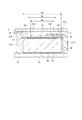
このため、地板21のアンテナ収容部21Cにおいて、平面アンテナ40のアンテナ電極42に対向する面、つまり文字板2側の面には、図3〜6に示すように、貫通孔216が形成されている。
本実施形態の貫通孔216は、アンテナ電極42の全体と平面的に重なるように構成されている。すなわち、アンテナ電極42は平面略矩形状に形成されているため、貫通孔216も電子時計1の表面側から見た平面視で矩形状に形成されている。
そして、平面矩形状の貫通孔216の一辺の寸法W1は、アンテナ電極42の一辺の寸法W2に比べて大きく設定され、誘電体基材41の一辺の寸法W3に比べて小さく設定されている。なお、本実施形態では、図6に示すように、貫通孔216の各四辺の寸法は同一としていたが、平面長方形状に形成されて図6において縦寸法および横寸法が異なる寸法とされていてもよい。
このようにアンテナ電極42に平面的に重なる地板21に貫通孔216を設けることで、アンテナ電極42に対向し、かつ1.0mm以下で近接する地板21(誘電体)が存在しなくなるので、アンテナ電極42と誘電体である地板21との間隔変動によってアンテナ周波数がシフトすることも抑制される。
For this reason, in the
The through
The dimension W1 of one side of the planar rectangular through-
Thus, by providing the through-
一方、壁部214間の寸法W4は前記寸法W3よりも大きくされ、平面アンテナ40の誘電体基材41が配置可能な寸法に設定されている。また、壁部214から突設される被覆部215は、誘電体基材41の露出面411に平面的に重なって配置されている。
そして、前記露出面411と被覆部215との間には、スポンジなどで構成された緩衝材47が配置されている。誘電体基材41を緩衝材47に接触させることで、平面アンテナ40の時計厚さ方向の位置が設定されている。また、誘電体基材41はセラミックで硬く欠けやすいが、緩衝材47が介在されているため、誘電体基材41が地板21に衝突することを防止できる。このため、誘電体基材41が地板21にぶつかって破損することも防止できる。
On the other hand, the dimension W4 between the
A cushioning
また、平面アンテナ40の文字板2側には、前記日車5の一部が配置される。この際、アンテナ電極42と日車5とは、少なくとも被覆部215の厚さ寸法分は離れているので、日車5がアンテナ周波数のシフトに影響することもない。
A part of the
[電子時計の回路構成]
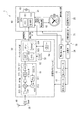
図8は、電子時計1の回路構成を示す概略図である。
電子時計1は、図8に示すように、平面アンテナ40と、フィルター(SAW)35と、受信部50と、制御表示部60と、電源供給部70を含んで構成されている。
フィルター35は、バンドパスフィルターであり、1.5GHzの衛星信号を通過させるものとなっている。また、平面アンテナ40とフィルター35との間に、受信感度を良好にするLNA(ローノイズアンプ)を別途組み込む構成としてもよい。
なお、フィルター35が受信部50内に組み込まれる構成としてもよい。
[Circuit configuration of electronic watch]
FIG. 8 is a schematic diagram showing a circuit configuration of the
As shown in FIG. 8, the
The
The
受信部50は、フィルター35を通過した衛星信号を処理するものであり、RF部(Radio Frequency:無線周波数)51とベースバンド部52を備える。
RF部51は、PLL回路511、VCO(Voltage Controlled Oscillator)512、LNA(Low Noise Amplifier)513、ミキサー514、IFアンプ515、IFフィルター516、ADC(A/D変換器)517等を備えている。
The receiving
The
そして、フィルター35を通過した衛星信号は、LNA513で増幅された後、ミキサー514でVCO512の信号とミキシングされ、IF(Intermediate Frequency:中間周波数)にダウンコンバートされる。
ミキサー514でミキシングされたIFは、IFアンプ515、IFフィルター516を通り、ADC(A/D変換器)517でデジタル信号に変換される。
The satellite signal that has passed through the
The IF mixed by the mixer 514 passes through an IF amplifier 515 and an IF filter 516, and is converted into a digital signal by an ADC (A / D converter) 517.
ベースバンド部52は、DSP(Digital Signal Processor)521、CPU(Central Processing Unit)522、RTC(リアルタイムクロック)523、SRAM(Static Random Access Memory)524を備えている。また、ベースバンド部52には、温度補償回路付き水晶発振回路(TCXO)53やフラッシュメモリー54等も接続されている。
そして、ベースバンド部52は、RF部51のADC517からデジタル信号が入力され、相関処理や測位演算等を行うことにより、衛星時刻情報や測位情報を取得できるようになっている。
なお、PLL回路511用のクロック信号は、温度補償回路付き水晶発振回路(TCXO)53から生成されるようになっている。
The
The
The clock signal for the
制御表示部60は、制御部(CPU)61と、指針3,4等の駆動を実施する駆動回路62と、時刻表示部および情報表示部等とを備えている。
制御部61は、RTC611、記憶部612を含んで構成されている。
RTC611は、水晶振動子63から出力される基準信号を用いて、内部時刻情報を計時している。
記憶部612は、受信部50から出力される衛星時刻情報や測位情報を記憶する。また、記憶部612には、測位情報に対応する時差データも記憶され、RTC611で計時されている内部時刻情報および時差データにより、現在地のローカルタイムを算出できるようにされている。
The
The
The
The storage unit 612 stores satellite time information and positioning information output from the receiving
本実施形態の電子時計1は、上述のような受信部50および制御表示部60を備えていることで、GPS衛星Sから受信した衛星信号に基づいて時刻表示を自動的に修正することができる。
The
電源供給部70は、太陽電池パネル25、充電制御回路71、二次電池24、第1レギュレーター72、第2レギュレーター73、電圧検出回路74を含んで構成されている。
The
太陽電池パネル25は、光が入射して発電すると、その光発電により得られる電力を、充電制御回路71を通じて二次電池24に供給して二次電池24を充電する。
二次電池24は、第1レギュレーター72を介して制御表示部60に駆動電力を供給し、第2レギュレーター73を介して受信部50に駆動電力を供給する。
電圧検出回路74は、二次電池24の電圧をモニターし、制御部61に出力する。従って、制御部61は、二次電池24の電圧を把握して受信処理を制御できる。
When the
The
The
[実施形態の作用効果]
平面アンテナ40のアンテナ電極42全体と平面的に重なる貫通孔216を地板21に形成することで、アンテナ電極42に近接する地板21が存在しないので、アンテナ電極42に誘電体である地板21が近接することによってアンテナ周波数がシフトすることを防止できる。このため、周波数の変動が少なくなり、アンテナ特性を安定化できる。
また、アンテナ電極42には貫通孔216が対向するため、平面アンテナ40の露出面411と、地板21の被覆部215との隙間をより小さくできる。このため、平面アンテナ40を内蔵するムーブメント20を薄型化でき、電子時計1も薄型化できる。
[Effects of Embodiment]
By forming a through-
Moreover, since the through-
さらに、平面アンテナ40の露出面411の少なくとも一部と平面的に重なる被覆部215を地板21に形成しているので、平面アンテナ40の時計表面側への移動を規制できる。したがって、電子時計1が落下した場合等に、平面アンテナ40が地板21の貫通孔216から飛び出して文字板2や日車5に衝突することも防止できる。
Furthermore, since the
地板21の被覆部215および誘電体基材41の露出面411間に緩衝材47を配置し、平面アンテナ40の露出面411を緩衝材47に当接させているので、電子時計1の高さ方向(厚さ方向)における平面アンテナ40の位置を精度よく設定できる。このため、地板21に対する平面アンテナ40の位置精度を向上でき、位置精度のばらつきによるアンテナ周波数の変化量をさらに低減できてアンテナ特性をより安定化できる。
さらに、平面アンテナ40の露出面411は、緩衝材47に当接するため、被覆部215に直接接触することを防止でき、セラミックで形成された誘電体基材41の破損を防止できる。
Since the
Furthermore, since the exposed
日車5を非導電性部材で形成したので、平面視において日車5を平面アンテナ40と重ねて配置しても、衛星信号は日車5を透過してアンテナに入射するため、受信性能が低下することを防止できる。
また、日車5は、平面視において平面アンテナ40と重なるため、日車5および平面アンテナ40を避けて配置する指針3、4の軸3A、4Aの配置位置の自由度が高まり、電子時計1のデザイン自由度を向上できる。
Since the
Further, since the
平面アンテナ40は、平面視において太陽電池パネル25と重ならないため、時計の表面側から伝播されてくる衛星信号は、太陽電池パネル25で遮られることなく平面アンテナ40に入射する。このため、受信性能を低下させることなく、太陽電池パネル25を電子時計1に設けることができる。
Since the
時計の表面側から見た平面視において、平面アンテナ40は、ケース本体11(外装ケース111およびベゼル112)と重なっていないため、時計の表面側から伝播されてくる衛星信号は、カバーガラス31を透過した後、ケース本体11で遮られることなく平面アンテナ40に入射する。このため、受信性能を低下させることなく、ケース本体11および裏蓋12を金属等の導電性部材にて形成でき、電子時計1の質感を向上できる。
また、ベゼル112を導電性部材にて形成しているので、ベゼル112をセラミック製とした場合に比べて加工が容易になりデザインの自由度を向上でき、コストも低減できる。また、ベゼル112は金属製のため、セラミック製のベゼルに比べて小さな断面積で剛性を確保できる。このため、リング状のベゼル112の断面幅寸法を小さくでき、カバーガラス31の平面サイズを大きくすることもでき、時計のデザインの自由度を向上できる。
Since the
Further, since the
外装ケース111および裏蓋12は、受信部50のグランド部に接続されるため、グランドプレーンとして機能する。これにより、グランドプレーンの面積を大きくとることができ、アンテナ利得が向上してアンテナ特性を向上できる。
Since the
[他の実施形態]
なお、本発明は前記実施形態に限定されず、本発明の要旨の範囲内で種々の変形実施が可能である。
[Other Embodiments]
In addition, this invention is not limited to the said embodiment, A various deformation | transformation implementation is possible within the range of the summary of this invention.
地板21のアンテナ収容部21Cに形成する貫通孔216は、平面アンテナ40のアンテナ電極42全体と平面的に重なる大きさに形成することが好ましいが、図9に示すように、貫通孔216の一辺の寸法W1をアンテナ電極42の一辺の寸法W2よりも小さくして、被覆部215がアンテナ電極42の一部に平面的に重なるように構成してもよい。
この場合でも、地板21に貫通孔216を形成しない場合に比べると、アンテナ電極42に近接する地板21つまり誘電体が少なくなり、アンテナ周波数がシフトする影響も軽減でき、アンテナ特性を安定化できる。
なお、図9に示すように、アンテナ電極42と、地板21(被覆部215)とが平面的に重なる場合、その重なる面積は小さいほうがアンテナ周波数のシフトの影響を軽減できる点で好ましく、前記重なる面積を概ねアンテナ電極42全体の面積の30%以下にすることが好ましい。
The through-
Even in this case, as compared with the case where the through-
In addition, as shown in FIG. 9, when the
また、図10に示す回路基板23Aおよび平面アンテナ40Aを用いてもよい。回路基板23Aは、電子時計1を薄型化するために、二次電池24と平面的に重なる部分に貫通孔231を形成している。そして、駆動体22のステップモーターや輪列などを二次電池24と平面的に重ならないように配置することで、ムーブメント20の厚さ寸法を小さくできる。
受信部50、制御部61等の各種ICは、回路基板23Aにおいて平面アンテナ40Aが実装される表面とは反対側の裏面側に実装されている。これにより、前記実施形態と同様に、受信回路や電源回路から発生するデジタルノイズが平面アンテナ40に入力し難くなるため、受信感度を向上できる。
Further, the
Various ICs such as the receiving
さらに、平面アンテナ40Aでは、誘電体基材41Aの表面に積層されるアンテナ電極42Aを回路基板23Aの平面中心位置側、つまり電子時計1の平面中心位置側にずらして形成している。このため、誘電体基材41Aの表面の露出面411Aにおいて、アンテナ電極42Aから外装ケース111側の露出面411Aの長さ寸法D1は、アンテナ電極42Aから回路基板23Aの平面中心位置側の露出面411Aの長さ寸法D2よりも大きく設定されている。言い換えると、アンテナ電極42Aの平面的な中心位置が、誘電体基材41Aの中心位置と一致しておらず、誘電体基材41Aの中心位置よりも電子時計1の平面中心位置側になるように形成されている。
また、長さ寸法D1は、平面視において、外装ケース111に最も近いアンテナ電極42Aの一辺から、外装ケース111に最も近い誘電体基材の一辺までの長さ寸法と言い換えることができる。そして、長さ寸法D2は、電子時計1の平面中心位置に最も近いアンテナ電極42Aの一辺から、電子時計1の平面中心位置に最も近い誘電体基材の一辺までの長さ寸法と言い換えることができる。
このように平面アンテナ40Aのアンテナ電極42Aを金属製の外装ケース111から離れるように配置することで、金属製の外装ケース111による電波の遮蔽の影響を低減することができる。
Further, in the
In addition, the length dimension D1 can be rephrased as a length dimension from one side of the
By arranging the
前記実施形態では、緩衝材47を配置していたが、緩衝材47を設けなくてもよい。この場合、平面アンテナ40の露出面411を被覆部215に当接させてもよい。また、平面アンテナ40の露出面411を被覆部215に当接させずに隙間が生じるように配置してもよい。
In the above embodiment, the
前記実施形態では、ケース本体11は、外装ケース111およびベゼル112によって構成されていたが、本発明はこれに限定されない。すなわち、外装ケース111のみによって構成されていてもよい。
In the embodiment, the case
前記実施形態では、ベゼル112は導電性部材で形成されているが、本発明はこれに限定されない。例えば、ベゼル112は、非導電性部材であるジルコニア(ZrO2)などのセラミックにて形成されていてもよい。ジルコニアは、抵抗率が高く電波受信に悪影響を与えないだけではなく、硬く耐傷性にも優れるため、時計の外装部材として優れている。また、ベゼル112をセラミック製とすると、ベゼル112をアンテナ電極42と平面視で重ねることができる。このため、ベゼル112がアンテナ電極42と平面的に重ならないように外装ケース111の直径を大きくする必要が無いため、外装ケース111の直径を小さくすることができ、電子時計1の平面サイズを小型化できる。
In the embodiment, the
前記実施形態では、電子時計1は、日車5、太陽電池パネル25、ダイヤルリング32を備えているが、本発明はこれに限定されない。すなわち、電子時計は、日車5、太陽電池パネル25、ダイヤルリング32を備えていなくてもよい。
In the said embodiment, although the
前記実施形態および前記変形例では、外装ケース111および裏蓋12は、受信部50のグランド部に接続されているが、本発明はこれに限定されない。すなわち、外装ケース111および裏蓋12は、当該グランド部に接続されていなくてもよい。
In the said embodiment and the said modification, the
前記実施形態および変形例では、電子時計は、文字板2および指針3からなる時刻表示部を備えているが、本発明はこれに限定されない。電子時計は、液晶パネル等からなる時刻表示部を備えていてもよい。この場合、時刻表示部を駆動する駆動体は、液晶パネルを駆動する駆動部を備えて構成される。
また、この場合、電子時計は時刻表示機能を備えていればよく、時刻表示部は、時刻表示専用の表示部である必要はない。このような電子時計としては、ユーザーの腕に装着されて脈拍を計測する脈拍計や、ユーザーがランニングを行う際などにユーザーの腕に装着されて現在位置を計測して蓄積するGPSロガー等のリスト型機器を例示できる。
In the said embodiment and modification, the electronic timepiece is provided with the time display part which consists of the
In this case, the electronic timepiece only needs to have a time display function, and the time display unit does not have to be a display unit dedicated to time display. Examples of such an electronic timepiece include a pulse meter that is mounted on the user's arm and measures a pulse, and a GPS logger that is mounted on the user's arm and measures and accumulates the current position when the user is running. A list type device can be exemplified.
位置情報衛星の例として、GPS衛星Sについて説明したが、これに限られない。例えば、位置情報衛星としては、ガリレオ(EU)、GLONASS(ロシア)、Beidou(中国)などの他の全地球的公航法衛星システム(GNSS)で利用される衛星が適用できる。また、静止衛星型衛星航法補強システム(SBAS)などの静止衛星や、準天頂衛星等の特定の地域のみで検索できる地域的衛星測位システム(RNSS)などの衛星も適用できる。 Although the GPS satellite S has been described as an example of the position information satellite, the present invention is not limited to this. For example, as the position information satellite, a satellite used in other global public navigation satellite systems (GNSS) such as Galileo (EU), GLONASS (Russia), and Beidou (China) can be applied. Further, a geostationary satellite such as a geostationary satellite type satellite navigation augmentation system (SBAS) or a satellite such as a regional satellite positioning system (RNSS) that can search only in a specific region such as a quasi-zenith satellite can be applied.
1…電子時計、5…日車、11…ケース本体、111…外装ケース、112…ベゼル、12…裏蓋、21…地板、21A…駆動体収容部、21B…日車配置部、21C…アンテナ収容部、、215…被覆部、216…貫通孔、22…駆動体、23,23A…回路基板、25…太陽電池パネル、、251…切欠部、40,40A…平面アンテナ、41,41A…誘電体基材、411,411A…露出面、42,42A…アンテナ電極、47…緩衝材。
DESCRIPTION OF
Claims (6)
前記地板の裏面側に配置される平面アンテナと、を備え、
前記平面アンテナは、誘電体基材と、前記誘電体基材の前記地板側の表面に積層されたアンテナ電極とを有し、
前記誘電体基材の表面には、前記アンテナ電極が積層されていない露出面が形成され、
前記平面アンテナにおいて、前記アンテナ電極が設けられた領域の表面は平面であり、
前記地板は、
前記アンテナ電極の少なくとも一部と平面的に重なる貫通孔と、
前記露出面の少なくとも一部と平面的に重なる被覆部とを有する
ことを特徴とする電子時計。 A base plate made of a non-conductive member;
A planar antenna disposed on the back side of the ground plane,
The planar antenna has a dielectric substrate and an antenna electrode laminated on the surface of the dielectric substrate on the ground plane side,
On the surface of the dielectric substrate, an exposed surface on which the antenna electrode is not laminated is formed,
In the planar antenna, the surface of the region where the antenna electrode is provided is a plane,
The main plate is
A through hole overlapping with at least a part of the antenna electrode in a plane,
An electronic timepiece comprising: a covering portion that planarly overlaps at least a part of the exposed surface.
前記被覆部と前記露出面との間には、緩衝材が配置されている
ことを特徴とする電子時計。 The electronic timepiece according to claim 1,
A buffer material is disposed between the covering portion and the exposed surface.
前記貫通孔は、少なくとも前記アンテナ電極の全体と平面的に重なって形成されている
ことを特徴とする電子時計。 The electronic timepiece according to claim 1 or 2,
The through-hole is formed so as to overlap with at least the entire antenna electrode in a planar manner.
前記被覆部は、前記アンテナ電極の一部に平面的に重なっており、且つ、重なる面積は前記アンテナ電極全体の面積の30%以下である
ことを特徴とする電子時計。 The electronic timepiece according to claim 1 or 2,
The electronic timepiece is characterized in that the covering portion overlaps a part of the antenna electrode in a planar manner, and an overlapping area is 30% or less of an entire area of the antenna electrode.
カレンダー情報を表示する非導電性部材からなるカレンダー車を備え、
前記平面アンテナは、前記カレンダー車と平面的に重なる位置に配置されている
ことを特徴とする電子時計。 The electronic timepiece according to any one of claims 1 to 4,
It has a calendar car made of non-conductive material that displays calendar information.
The electronic timepiece according to claim 1, wherein the planar antenna is disposed at a position overlapping with the calendar wheel in a planar manner.
前記地板の表面側に設けられ、前記平面アンテナと平面的に重ならない太陽電池パネル
を備える
ことを特徴とする電子時計。 The electronic timepiece according to any one of claims 1 to 5,
An electronic timepiece comprising a solar cell panel provided on a surface side of the ground plane and not planarly overlapping with the planar antenna.
Priority Applications (2)
| Application Number | Priority Date | Filing Date | Title |
|---|---|---|---|
| JP2014208140A JP6458437B2 (en) | 2014-10-09 | 2014-10-09 | Electronic clock |
| US14/851,298 US9886003B2 (en) | 2014-10-09 | 2015-09-11 | Electronic timepiece |
Applications Claiming Priority (1)
| Application Number | Priority Date | Filing Date | Title |
|---|---|---|---|
| JP2014208140A JP6458437B2 (en) | 2014-10-09 | 2014-10-09 | Electronic clock |
Publications (3)
| Publication Number | Publication Date |
|---|---|
| JP2016080356A JP2016080356A (en) | 2016-05-16 |
| JP2016080356A5 JP2016080356A5 (en) | 2017-11-09 |
| JP6458437B2 true JP6458437B2 (en) | 2019-01-30 |
Family
ID=55655389
Family Applications (1)
| Application Number | Title | Priority Date | Filing Date |
|---|---|---|---|
| JP2014208140A Active JP6458437B2 (en) | 2014-10-09 | 2014-10-09 | Electronic clock |
Country Status (2)
| Country | Link |
|---|---|
| US (1) | US9886003B2 (en) |
| JP (1) | JP6458437B2 (en) |
Families Citing this family (11)
| Publication number | Priority date | Publication date | Assignee | Title |
|---|---|---|---|---|
| JP1549158S (en) * | 2015-01-07 | 2016-05-16 | ||
| CN206372035U (en) * | 2016-10-10 | 2017-08-04 | 东莞市坚野材料科技有限公司 | The wearable device that amorphous alloy with antibacterial functions is made |
| CN106842899A (en) * | 2017-03-01 | 2017-06-13 | 北京数科技有限公司 | A kind of intelligent watch |
| CH714069A1 (en) | 2017-08-17 | 2019-02-28 | Soprod Sa | Electromechanical watchmaking module comprising an antenna. |
| CN111164519B (en) * | 2017-10-04 | 2021-11-02 | 西铁城时计株式会社 | Radio controlled timepiece |
| CN107817673B (en) * | 2017-11-20 | 2020-10-27 | 深圳市沃特沃德股份有限公司 | Wearable device |
| JP7172474B2 (en) * | 2018-03-06 | 2022-11-16 | セイコーエプソン株式会社 | electronic clock |
| CN110231771B (en) | 2018-03-06 | 2022-03-01 | 精工爱普生株式会社 | Electronic clock |
| JP6996372B2 (en) * | 2018-03-19 | 2022-01-17 | セイコーエプソン株式会社 | Electronic clock |
| CN108762057B (en) * | 2018-06-27 | 2021-02-12 | 成都天奥电子股份有限公司 | Watch with metal watch case |
| CN111025880A (en) * | 2019-12-03 | 2020-04-17 | 深圳市万机创意电子科技有限公司 | Hand-manipulating watch capable of realizing heart rate indication function by second hand |
Family Cites Families (18)
| Publication number | Priority date | Publication date | Assignee | Title |
|---|---|---|---|---|
| US5642120A (en) * | 1993-03-29 | 1997-06-24 | Seiko Epson Corporation | Antenna device and wireless apparatus employing the same |
| EP1274150A1 (en) * | 2001-07-05 | 2003-01-08 | Eta SA Fabriques d'Ebauches | Wrist-watch with antenna |
| JP3594034B1 (en) | 2003-03-04 | 2004-11-24 | セイコーエプソン株式会社 | Radio-controlled clock |
| JP4412366B2 (en) | 2003-03-04 | 2010-02-10 | セイコーエプソン株式会社 | Electronic wristwatch with wireless function |
| EP1489471A1 (en) * | 2003-06-18 | 2004-12-22 | Asulab S.A. | Ground connection of a printed circuit board placed in a wristwatch-type electronic device |
| JP2010066045A (en) * | 2008-09-09 | 2010-03-25 | Casio Comput Co Ltd | Radio wave receiving system |
| JP5569668B2 (en) * | 2008-10-20 | 2014-08-13 | セイコーエプソン株式会社 | Electronic watch |
| JP5609310B2 (en) * | 2009-09-01 | 2014-10-22 | セイコーエプソン株式会社 | Antenna built-in clock |
| JP5413318B2 (en) | 2010-07-05 | 2014-02-12 | セイコーエプソン株式会社 | Electronic clock |
| JP5570462B2 (en) | 2011-03-18 | 2014-08-13 | シチズンホールディングス株式会社 | Electronics |
| JP5568497B2 (en) * | 2011-03-22 | 2014-08-06 | シチズンホールディングス株式会社 | Clock with solar battery |
| JP5933990B2 (en) * | 2011-03-22 | 2016-06-15 | シチズンホールディングス株式会社 | Clock with solar battery |
| JP5715527B2 (en) | 2011-08-11 | 2015-05-07 | シチズンホールディングス株式会社 | Radio wave watch |
| EP2821863B1 (en) * | 2012-02-29 | 2019-09-25 | Seiko Epson Corporation | Integral-antenna-type electronic clock |
| CN103676631B (en) * | 2012-09-24 | 2016-08-10 | 精工爱普生株式会社 | Electronic timepiece with internal antenna |
| US9531067B2 (en) * | 2013-02-08 | 2016-12-27 | Ubiquiti Networks, Inc. | Adjustable-tilt housing with flattened dome shape, array antenna, and bracket mount |
| JP2016080357A (en) * | 2014-10-09 | 2016-05-16 | セイコーエプソン株式会社 | Electronic watch |
| JP6459455B2 (en) * | 2014-12-04 | 2019-01-30 | セイコーエプソン株式会社 | Electronic clock |
-
2014
- 2014-10-09 JP JP2014208140A patent/JP6458437B2/en active Active
-
2015
- 2015-09-11 US US14/851,298 patent/US9886003B2/en active Active
Also Published As
| Publication number | Publication date |
|---|---|
| US20160103428A1 (en) | 2016-04-14 |
| US9886003B2 (en) | 2018-02-06 |
| JP2016080356A (en) | 2016-05-16 |
Similar Documents
| Publication | Publication Date | Title |
|---|---|---|
| JP6459455B2 (en) | Electronic clock | |
| JP6458437B2 (en) | Electronic clock | |
| JP6696195B2 (en) | Electronic clock | |
| EP2749969B1 (en) | Timeepiece with wireless communication function | |
| JP5866860B2 (en) | Clock with wireless function | |
| JP6459647B2 (en) | Electronic timepiece and control method of electronic timepiece | |
| JP6699769B2 (en) | Electronic clock | |
| US8562207B2 (en) | Electronic timepiece | |
| US8804466B2 (en) | Electronic timepiece | |
| US11221591B2 (en) | Electronic timepiece having a conductive member spaced apart from a planar antenna | |
| JP2012093211A (en) | Antenna built-in electronic timepiece | |
| JP2016080357A (en) | Electronic watch | |
| JP2012107955A (en) | Antenna built-in electronic timepiece | |
| CN110286581B (en) | Electronic clock | |
| JP6540351B2 (en) | Electronic clock and control method of electronic clock | |
| JP5741734B2 (en) | Clock with wireless function | |
| US20180284700A1 (en) | Electronic Timepiece | |
| JP2018169383A (en) | Electronic clock |
Legal Events
| Date | Code | Title | Description |
|---|---|---|---|
| A521 | Request for written amendment filed |
Free format text: JAPANESE INTERMEDIATE CODE: A523 Effective date: 20170926 |
|
| A621 | Written request for application examination |
Free format text: JAPANESE INTERMEDIATE CODE: A621 Effective date: 20170926 |
|
| A977 | Report on retrieval |
Free format text: JAPANESE INTERMEDIATE CODE: A971007 Effective date: 20180817 |
|
| A131 | Notification of reasons for refusal |
Free format text: JAPANESE INTERMEDIATE CODE: A131 Effective date: 20180911 |
|
| A521 | Request for written amendment filed |
Free format text: JAPANESE INTERMEDIATE CODE: A523 Effective date: 20181112 |
|
| TRDD | Decision of grant or rejection written | ||
| A01 | Written decision to grant a patent or to grant a registration (utility model) |
Free format text: JAPANESE INTERMEDIATE CODE: A01 Effective date: 20181127 |
|
| A61 | First payment of annual fees (during grant procedure) |
Free format text: JAPANESE INTERMEDIATE CODE: A61 Effective date: 20181210 |
|
| R150 | Certificate of patent or registration of utility model |
Ref document number: 6458437 Country of ref document: JP Free format text: JAPANESE INTERMEDIATE CODE: R150 |