JP6456552B2 - System and method for reducing interference using polarization diversity - Google Patents
System and method for reducing interference using polarization diversity Download PDFInfo
- Publication number
- JP6456552B2 JP6456552B2 JP2018512386A JP2018512386A JP6456552B2 JP 6456552 B2 JP6456552 B2 JP 6456552B2 JP 2018512386 A JP2018512386 A JP 2018512386A JP 2018512386 A JP2018512386 A JP 2018512386A JP 6456552 B2 JP6456552 B2 JP 6456552B2
- Authority
- JP
- Japan
- Prior art keywords
- polarizations
- interference
- interface
- receive
- polarization
- Prior art date
- Legal status (The legal status is an assumption and is not a legal conclusion. Google has not performed a legal analysis and makes no representation as to the accuracy of the status listed.)
- Expired - Fee Related
Links
Images


Classifications
-
- H—ELECTRICITY
- H04—ELECTRIC COMMUNICATION TECHNIQUE
- H04B—TRANSMISSION
- H04B7/00—Radio transmission systems, i.e. using radiation field
- H04B7/02—Diversity systems; Multi-antenna system, i.e. transmission or reception using multiple antennas
- H04B7/10—Polarisation diversity; Directional diversity
-
- H—ELECTRICITY
- H04—ELECTRIC COMMUNICATION TECHNIQUE
- H04B—TRANSMISSION
- H04B7/00—Radio transmission systems, i.e. using radiation field
- H04B7/02—Diversity systems; Multi-antenna system, i.e. transmission or reception using multiple antennas
- H04B7/04—Diversity systems; Multi-antenna system, i.e. transmission or reception using multiple antennas using two or more spaced independent antennas
- H04B7/0413—MIMO systems
- H04B7/0456—Selection of precoding matrices or codebooks, e.g. using matrices antenna weighting
- H04B7/046—Selection of precoding matrices or codebooks, e.g. using matrices antenna weighting taking physical layer constraints into account
- H04B7/0469—Selection of precoding matrices or codebooks, e.g. using matrices antenna weighting taking physical layer constraints into account taking special antenna structures, e.g. cross polarized antennas into account
-
- H—ELECTRICITY
- H04—ELECTRIC COMMUNICATION TECHNIQUE
- H04B—TRANSMISSION
- H04B7/00—Radio transmission systems, i.e. using radiation field
- H04B7/02—Diversity systems; Multi-antenna system, i.e. transmission or reception using multiple antennas
- H04B7/04—Diversity systems; Multi-antenna system, i.e. transmission or reception using multiple antennas using two or more spaced independent antennas
- H04B7/08—Diversity systems; Multi-antenna system, i.e. transmission or reception using multiple antennas using two or more spaced independent antennas at the receiving station
- H04B7/0837—Diversity systems; Multi-antenna system, i.e. transmission or reception using multiple antennas using two or more spaced independent antennas at the receiving station using pre-detection combining
- H04B7/0842—Weighted combining
- H04B7/0848—Joint weighting
- H04B7/0857—Joint weighting using maximum ratio combining techniques, e.g. signal-to- interference ratio [SIR], received signal strenght indication [RSS]
-
- H—ELECTRICITY
- H04—ELECTRIC COMMUNICATION TECHNIQUE
- H04W—WIRELESS COMMUNICATION NETWORKS
- H04W24/00—Supervisory, monitoring or testing arrangements
- H04W24/02—Arrangements for optimising operational condition
Landscapes
- Engineering & Computer Science (AREA)
- Computer Networks & Wireless Communication (AREA)
- Signal Processing (AREA)
- Mobile Radio Communication Systems (AREA)
- Radio Transmission System (AREA)
Description
関連出願の相互参照
本出願は、その内容全体が組み込まれる、2015年9月15日に米国特許商標庁に出願された非仮出願第14/855,283号の優先権および利益を主張する。
This application claims the priority and benefit of non-provisional application No. 14 / 855,283 filed with the US Patent and Trademark Office on September 15, 2015, the entire contents of which are incorporated.
本開示は、一般に、ワイヤレス通信に関し、詳細には、偏波ダイバーシティを使用して干渉を低減するためのシステムおよび方法に関する。 The present disclosure relates generally to wireless communications, and more particularly to systems and methods for reducing interference using polarization diversity.
ワイヤレス通信システムのために必要とされる帯域幅要件が増大している問題に対処するために、様々な方式が開発されつつある。いくつかの方式では、データは、60GHz周波数帯域の中の1つまたは複数のチャネルを介して、高データレート(たとえば、数ギガビット/秒)でワイヤレスに送信される。 Various schemes are being developed to address the problem of increasing bandwidth requirements needed for wireless communication systems. In some schemes, data is transmitted wirelessly at high data rates (eg, several gigabits per second) over one or more channels in the 60 GHz frequency band.
本開示のいくつかの態様は、ワイヤレス通信のための方法を提供する。方法は、2つ以上の偏波のうちの各偏波において、少なくとも1つの干渉源からの干渉を受信するステップと、2つ以上の偏波のうちの各偏波において、受信された干渉の強度を測定するステップと、測定干渉強度に基づいて2つ以上の偏波のうちの1つを選択するステップと、2つ以上の偏波のうちの選択された偏波を使用してリモートデバイスと通信するステップとを備える。 Certain aspects of the present disclosure provide a method for wireless communication. The method includes receiving interference from at least one interference source in each of the two or more polarizations, and receiving received interference in each of the two or more polarizations. Measuring the intensity, selecting one of the two or more polarizations based on the measured interference strength, and using the selected polarization of the two or more polarizations to the remote device Communicating with.
本開示のいくつかの態様は、ワイヤレス通信のための装置を提供する。装置は、2つ以上の偏波のうちの各偏波において、少なくとも1つの干渉源からの干渉を受信するように構成されたインターフェースを備える。装置はまた、2つ以上の偏波のうちの各偏波において、受信された干渉の強度を測定し、測定干渉強度に基づいて2つ以上の偏波のうちの1つを選択し、2つ以上の偏波のうちの選択された偏波を使用してインターフェースを介してリモートデバイスと通信するように構成された処理システムを備える。 Certain aspects of the present disclosure provide an apparatus for wireless communication. The apparatus comprises an interface configured to receive interference from at least one interference source in each polarization of the two or more polarizations. The device also measures the strength of the received interference in each polarization of the two or more polarizations and selects one of the two or more polarizations based on the measured interference strength. A processing system configured to communicate with a remote device via an interface using a selected polarization of the one or more polarizations.
本開示のいくつかの態様は、ワイヤレス通信のための装置を提供する。装置は、2つ以上の偏波のうちの各偏波において、少なくとも1つの干渉源からの干渉を受信するための手段と、2つ以上の偏波のうちの各偏波において、受信された干渉の強度を測定するための手段と、測定干渉強度に基づいて2つ以上の偏波のうちの1つを選択するための手段と、2つ以上の偏波のうちの選択された偏波を使用してリモートデバイスと通信するための手段とを備える。 Certain aspects of the present disclosure provide an apparatus for wireless communication. The apparatus received in each polarization of the two or more polarizations, and means for receiving interference from at least one interference source in each of the two or more polarizations Means for measuring the strength of the interference, means for selecting one of the two or more polarizations based on the measured interference strength, and a selected polarization of the two or more polarizations And means for communicating with the remote device.
本開示のいくつかの態様は、コンピュータ可読媒体を提供する。コンピュータ可読媒体は、その上に記憶された命令を備え、命令は、2つ以上の偏波のうちの各偏波において、少なくとも1つの干渉源からの干渉を受信し、2つ以上の偏波のうちの各偏波において、受信された干渉の強度を測定し、測定干渉強度に基づいて2つ以上の偏波のうちの1つを選択し、2つ以上の偏波のうちの選択された偏波を使用してリモートデバイスと通信するためのものである。 Some aspects of the present disclosure provide a computer-readable medium. The computer-readable medium comprises instructions stored thereon, the instructions receiving interference from at least one interference source in each polarization of the two or more polarizations, and the two or more polarizations For each polarization, measure the strength of the received interference, select one of the two or more polarizations based on the measured interference strength, and select one of the two or more polarizations To communicate with remote devices using polarized light.
本開示のいくつかの態様は、ワイヤレスノードを提供する。ワイヤレスノードは、少なくとも1つのアンテナと、2つ以上の偏波のうちの各偏波において、少なくとも1つの干渉源からの干渉を少なくとも1つのアンテナを介して受信するように構成されたトランシーバとを備える。ワイヤレスノードはまた、2つ以上の偏波のうちの各偏波において、受信された干渉の強度を測定し、測定干渉強度に基づいて2つ以上の偏波のうちの1つを選択し、2つ以上の偏波のうちの選択された偏波を使用してトランシーバおよび少なくとも1つのアンテナを介してリモートデバイスと通信するように構成された処理システムを備える。 Some aspects of the present disclosure provide a wireless node. The wireless node includes at least one antenna and a transceiver configured to receive interference from at least one interference source via at least one antenna in each of the two or more polarizations. Prepare. The wireless node also measures the strength of the received interference in each polarization of the two or more polarizations, and selects one of the two or more polarizations based on the measured interference strength, A processing system configured to communicate with a remote device via a transceiver and at least one antenna using a selected polarization of two or more polarizations.
本開示の様々な態様が、添付の図面を参照しながら以下でより十分に説明される。しかしながら、本開示は、多くの異なる形態で具現化されてよく、本開示全体にわたって提示される任意の特定の構造または機能に限定されるものと解釈されるべきでない。むしろ、これらの態様は、本開示が周到で完全になり、本開示の範囲を当業者に十分に伝えるように与えられる。本明細書の教示に基づいて、本開示の範囲が、本開示の任意の他の態様とは無関係に実施されるにせよ、本開示の任意の他の態様と組み合わせて実施されるにせよ、本明細書で開示する本開示の任意の態様を包含するように意図されることを当業者は諒解されたい。たとえば、本明細書に記載する任意の数の態様を使用して、装置が実装されてよく、または方法が実践されてよい。加えて、本開示の範囲は、本明細書に記載する本開示の様々な態様に加えて、またはそうした態様以外に、他の構造、機能、または構造および機能を使用して実践されるそのような装置または方法を包含するように意図される。本明細書で開示する本開示のいかなる態様も、請求項の1つまたは複数の要素によって具現化され得ることを理解されたい。 Various aspects of the disclosure are described more fully hereinafter with reference to the accompanying drawings. However, this disclosure may be embodied in many different forms and should not be construed as limited to any particular structure or function presented throughout this disclosure. Rather, these aspects are provided so that this disclosure will be thorough and complete, and will fully convey the scope of the disclosure to those skilled in the art. Based on the teachings herein, whether the scope of the present disclosure is implemented independently of any other aspect of the present disclosure, or in combination with any other aspect of the present disclosure, Those skilled in the art should appreciate that they are intended to encompass any aspect of the present disclosure disclosed herein. For example, an apparatus may be implemented or a method may be practiced using any number of aspects described herein. In addition, the scope of the present disclosure may be practiced using other structures, functions, or structures and functions in addition to or in addition to the various aspects of the present disclosure described herein. Intended to encompass any apparatus or method. It should be understood that any aspect of the disclosure disclosed herein may be embodied by one or more elements of a claim.
「例示的」という単語は、本明細書では、「例、事例、または例示として機能すること」を意味するために使用される。「例示的」として本明細書で説明するいかなる態様も、必ずしも他の態様よりも好ましいか、または有利であると解釈されるべきでない。 The word “exemplary” is used herein to mean “serving as an example, instance, or illustration”. Any aspect described herein as "exemplary" is not necessarily to be construed as preferred or advantageous over other aspects.
特定の態様が本明細書で説明されるが、これらの態様の多くの変形および置換が本開示の範囲内に入る。好ましい態様のいくつかの利益および利点が述べられるが、本開示の範囲は特定の利益、使用、または目的に限定されるように意図されない。むしろ、本開示の態様は、様々なワイヤレス技術、システム構成、ネットワーク、および伝送プロトコルに広く適用可能であることが意図され、そのうちのいくつかが例として図面および好ましい態様の以下の説明において示される。発明を実施するための形態および図面は、限定的でなく、本開示の例示にすぎず、本開示の範囲は、添付の特許請求の範囲およびその均等物によって定義される。 Although particular aspects are described herein, many variations and permutations of these aspects fall within the scope of the disclosure. Although some benefits and advantages of the preferred aspects are mentioned, the scope of the disclosure is not intended to be limited to particular benefits, uses, or objectives. Rather, aspects of the present disclosure are intended to be broadly applicable to various wireless technologies, system configurations, networks, and transmission protocols, some of which are illustrated by way of example in the drawings and the following description of preferred embodiments. . The detailed description and drawings are merely illustrative of the disclosure rather than limiting, the scope of the disclosure being defined by the appended claims and equivalents thereof.
本明細書で説明する技法は、直交多重化方式に基づく通信システムを含む様々な広帯域ワイヤレス通信システムのために使用され得る。そのような通信システムの例は、空間分割多元接続(SDMA)、時分割多元接続(TDMA)、直交周波数分割多元接続(OFDMA)システム、シングルキャリア周波数分割多元接続(SC-FDMA)システムなどを含む。SDMAシステムは、複数のアクセス端末に属するデータを同時に送信するために、十分に異なる方向を利用し得る。TDMAシステムは、送信信号を異なるタイムスロットに分割することによって、複数のアクセス端末が同じ周波数チャネルを共有することを可能にし得、各タイムスロットは、異なるアクセス端末に割り当てられる。OFDMAシステムは、システム帯域幅全体を複数の直交するサブキャリアに区分する変調技法である直交周波数分割多重化(OFDM)を利用する。これらのサブキャリアは、トーン、ビンなどと呼ばれることもある。OFDMでは、各サブキャリアはデータを用いて独立して変調され得る。SC-FDMAシステムは、システム帯域幅にわたって分散されるサブキャリア上で送信するためのインターリーブFDMA(IFDMA)、隣接するサブキャリアのブロック上で送信するための局所化FDMA(LFDMA)、または隣接するサブキャリアの複数のブロック上で送信するための拡張FDMA(EFDMA)を利用し得る。概して、変調シンボルは、OFDMでは周波数領域において送られ、SC-FDMAでは時間領域において送られる。 The techniques described herein may be used for various broadband wireless communication systems, including communication systems that are based on an orthogonal multiplexing scheme. Examples of such communication systems include space division multiple access (SDMA), time division multiple access (TDMA), orthogonal frequency division multiple access (OFDMA) systems, single carrier frequency division multiple access (SC-FDMA) systems, etc. . An SDMA system may utilize sufficiently different directions to transmit data belonging to multiple access terminals simultaneously. A TDMA system may allow multiple access terminals to share the same frequency channel by dividing the transmitted signal into different time slots, where each time slot is assigned to a different access terminal. The OFDMA system utilizes orthogonal frequency division multiplexing (OFDM), which is a modulation technique that partitions the entire system bandwidth into multiple orthogonal subcarriers. These subcarriers are sometimes called tones, bins, etc. In OFDM, each subcarrier can be independently modulated with data. SC-FDMA systems are interleaved FDMA (IFDMA) for transmitting on subcarriers distributed across the system bandwidth, localized FDMA (LFDMA) for transmitting on blocks of adjacent subcarriers, or adjacent subcarriers. Enhanced FDMA (EFDMA) may be utilized for transmitting on multiple blocks of the carrier. In general, modulation symbols are sent in the frequency domain with OFDM and in the time domain with SC-FDMA.
本明細書の教示は、様々な有線またはワイヤレスの装置(たとえば、ノード)に組み込まれてよい(たとえば、そうした装置内に実装されるか、またはそうした装置によって実行されてもよい)。いくつかの態様では、本明細書の教示に従って実装されるワイヤレスノードは、アクセスポイントまたはアクセス端末を備え得る。 The teachings herein may be incorporated into (eg, implemented in or performed by) various wired or wireless devices (eg, nodes). In some aspects, a wireless node implemented in accordance with the teachings herein may comprise an access point or access terminal.
アクセスポイント(「AP」)は、ノードB、無線ネットワークコントローラ(「RNC」)、発展型ノードB(eNB)、基地局コントローラ(「BSC」)、基地トランシーバ局(「BTS」)、基地局(「BS」)、トランシーバ機能(「TF」)、無線ルータ、無線トランシーバ、基本サービスセット(「BSS」)、拡張サービスセット(「ESS」)、無線基地局(「RBS」)、または何らかの他の用語を備えることがあるか、それらとして実装されることがあるか、またはそれらと知られていることがある。 Access point (`` AP '') is Node B, Radio Network Controller (`` RNC ''), Evolved Node B (eNB), Base Station Controller (`` BSC ''), Base Transceiver Station (`` BTS ''), Base Station ( "BS"), transceiver function ("TF"), wireless router, wireless transceiver, basic service set ("BSS"), extended service set ("ESS"), radio base station ("RBS"), or some other May have terminology, may be implemented as such, or may be known as such.
アクセス端末(「AT」)は、加入者局、加入者ユニット、移動局、リモート局、リモート端末、ユーザ端末、ユーザエージェント、ユーザデバイス、ユーザ機器、ユーザ局、または何らかの他の用語を備えることがあるか、それらとして実装されることがあるか、またはそれらと知られていることがある。いくつかの実装形態では、アクセス端末は、セルラー電話、コードレス電話、セッション開始プロトコル(「SIP」)電話、ワイヤレスローカルループ(「WLL」)局、携帯情報端末(「PDA」)、ワイヤレス接続機能を有するハンドヘルドデバイス、ステーション(「STA」)、またはワイヤレスモデムに接続された何らかの他の好適な処理デバイスを備えることがある。したがって、本明細書で教示する1つまたは複数の態様は、電話(たとえば、セルラーフォンまたはスマートフォン)、コンピュータ(たとえば、ラップトップ)、ポータブル通信デバイス、ポータブルコンピューティングデバイス(たとえば、携帯情報端末)、エンターテインメントデバイス(たとえば、音楽デバイスもしくはビデオデバイス、または衛星ラジオ)、全地球測位システムデバイス、またはワイヤレスもしくは有線の媒体を介して通信するように構成されている任意の他の好適なデバイスに組み込まれ得る。いくつかの態様では、ノードはワイヤレスノードである。そのようなワイヤレスノードは、たとえば、有線またはワイヤレスの通信リンクを介して、ネットワーク(たとえば、インターネットまたはセルラーネットワークなどのワイドエリアネットワーク)のための接続性またはネットワークへの接続性を提供し得る。 An access terminal (“AT”) may comprise a subscriber station, subscriber unit, mobile station, remote station, remote terminal, user terminal, user agent, user device, user equipment, user station, or some other terminology. May be implemented as them, or may be known as them. In some implementations, the access terminal has a cellular phone, cordless phone, session initiation protocol (“SIP”) phone, wireless local loop (“WLL”) station, personal digital assistant (“PDA”), wireless connectivity capability. May have a handheld device, a station ("STA"), or some other suitable processing device connected to a wireless modem. Accordingly, one or more aspects taught herein include a telephone (e.g., a cellular phone or a smartphone), a computer (e.g., a laptop), a portable communication device, a portable computing device (e.g., a personal digital assistant), Can be incorporated into an entertainment device (e.g., music or video device, or satellite radio), global positioning system device, or any other suitable device that is configured to communicate via a wireless or wired medium . In some aspects, the node is a wireless node. Such wireless nodes may provide connectivity for or connectivity to a network (eg, a wide area network such as the Internet or a cellular network) via, for example, a wired or wireless communication link.
図1は、アクセスポイントおよびアクセス端末などの複数のワイヤレスノードを有するワイヤレス通信システム100の一例のブロック図を示す。簡単にするために、1つのアクセスポイント110だけが示される。アクセスポイントは、一般に、アクセス端末と通信する固定局であり、基地局または何らかの他の用語で呼ばれることもある。アクセス端末は、固定またはモバイルであってよく、移動局、ワイヤレスデバイス、または何らかの他の用語で呼ばれることがある。アクセスポイント110は、ダウンリンクおよびアップリンク上で任意の所与の瞬間において1つまたは複数のアクセス端末120a〜120iと通信し得る。ダウンリンク(すなわち、順方向リンク)は、アクセスポイントからアクセス端末への通信リンクであり、アップリンク(すなわち、逆方向リンク)は、アクセス端末からアクセスポイントへの通信リンクである。アクセス端末はまた、別のアクセス端末とピアツーピアで通信し得る。システムコントローラ130は、アクセスポイントに結合し、アクセスポイントのための協調および制御を行う。アクセスポイント110は、バックボーンネットワーク150に結合された他のデバイスと通信し得る。
FIG. 1 shows a block diagram of an example of a
図2は、ワイヤレス通信システム100におけるアクセスポイント110(一般に、第1のワイヤレスノード)およびアクセス端末120(一般に、第2のワイヤレスノード)のブロック図を示す。アクセスポイント110は、ダウンリンク用の送信エンティティかつアップリンク用の受信エンティティである。アクセス端末120は、アップリンク用の送信エンティティかつダウンリンク用の受信エンティティである。本明細書で使用するとき、「送信エンティティ」は、ワイヤレスチャネルを介してデータを送信することが可能な独立動作型の装置またはワイヤレスノードであり、「受信エンティティ」は、ワイヤレスチャネルを介してデータを受信することが可能な独立動作型の装置またはワイヤレスノードである。
FIG. 2 shows a block diagram of an access point 110 (typically a first wireless node) and an access terminal 120 (typically a second wireless node) in the
この例では、ワイヤレスノード110がアクセスポイントでありワイヤレスノード120がアクセス端末であるが、ワイヤレスノード110が、代替として、アクセス端末であってよく、ワイヤレスノード120が、代替として、アクセスポイントであってよいことを理解されたい。
In this example,
データを送信するために、アクセスポイント110は、送信データプロセッサ220、フレームビルダー222、送信プロセッサ224、複数のトランシーバ226-1〜226-N、および複数のアンテナ230-1〜230-Nを備える。アクセスポイント110はまた、以下でさらに説明するように、アクセスポイント110の動作を制御するように構成されたコントローラ234を備える。
To transmit data, the
動作においては、送信データプロセッサ220が、データソース215からデータ(たとえば、データビット)を受信し、送信用にデータを処理する。たとえば、送信データプロセッサ220は、データ(たとえば、データビット)を符号化して符号化データにし得、符号化データを変調してデータシンボルにし得る。送信データプロセッサ220は、様々な変調およびコーディング方式(MCS)をサポートし得る。たとえば、送信データプロセッサ220は、複数の異なるコーディングレートのいずれか1つで(たとえば、低密度パリティチェック(LDPC)符号化を使用して)データを符号化し得る。また、送信データプロセッサ220は、限定はしないが、BPSK、QPSK、16QAM、64QAM、64APSK、128APSK、256QAM、および256APSKを含む、複数の異なる変調方式のいずれか1つを使用して、符号化データを変調し得る。
In operation, the transmit
いくつかの態様では、コントローラ234は、(たとえば、ダウンリンクのチャネル状態に基づいて)どの変調およびコーディング方式(MCS)を使用すべきかを規定するコマンドを送信データプロセッサ220に送ってよく、送信データプロセッサ220は、規定されたMCSに従ってデータソース215からのデータを符号化および変調してよい。送信データプロセッサ220が、データスクランブリングおよび/または他の処理などの、データへの追加の処理を実行してもよいことを諒解されたい。送信データプロセッサ220は、データシンボルをフレームビルダー222に出力する。
In some aspects, the
フレームビルダー222は、フレーム(パケットとも呼ばれる)を構築し、フレームのデータペイロードにデータシンボルを挿入する。例示的なフレーム構造310が、図3に示される。この例では、フレーム構造310は、プリアンブル315、ヘッダ320、およびデータペイロード325を含む。プリアンブル315は、フレームを受信する際にアクセス端末120を支援するための、ショートトレーニングフィールド(STF)シーケンスおよびチャネル推定(CE)シーケンスを含み得る。ヘッダ320は、ペイロードの中のデータに関係する情報を含み得る。たとえば、ヘッダ320は、フレームおよび/またはペイロードの持続時間を示す持続時間フィールド(長さフィールドとも呼ばれる)、ならびにペイロードの中のデータを符号化および変調するために使用されたMCSを示すMCSフィールドを含み得る。この情報により、アクセス端末120がデータを復調および復号することが可能になる。ヘッダ320はまた、ペイロード325の中のデータの宛先(たとえば、アクセス端末120)を識別する宛先アドレスフィールドを含み得る。フレームビルダー222は、フレームを送信プロセッサ224に出力する。
The
図2に戻ると、送信プロセッサ224は、ダウンリンク上での送信用にフレームを処理する。たとえば、送信プロセッサ224は、直交周波数分割多重(OFDM)送信モードおよびシングルキャリア(SC)送信モードなどの様々な送信モードをサポートし得る。この例では、コントローラ234は、どの送信モードを使用すべきかを規定するコマンドを送信プロセッサ224に送ってよく、送信プロセッサ224は、規定された送信モードに従って送信用にフレームを処理してよい。
Returning to FIG. 2, the transmit
いくつかの態様では、送信プロセッサ224は、多入力多出力(MIMO)送信をサポートし得る。これらの態様では、アクセスポイント110は、複数のアンテナ230-1〜230-Nおよび複数のトランシーバ226-1〜226-N(たとえば、アンテナごとに1つ)を含む。送信プロセッサ224は、着信フレームに空間処理を実行し得、複数の送信フレームストリームを複数のアンテナに提供し得る。トランシーバ226-1〜226-Nは、それぞれの送信フレームストリームを受信し、かつ処理(たとえば、アナログに変換、増幅、フィルタ処理、および周波数アップコンバート)して、アンテナ230-1〜230-Nを介した送信用に送信信号を生成する。
In some aspects, the transmit
データを送信するために、アクセス端末120は、送信データプロセッサ260、フレームビルダー262、送信プロセッサ264、複数のトランシーバ266-1〜266-N、および複数のアンテナ270-1〜270-Nを備える。アクセス端末120は、アップリンク上でアクセスポイント110へデータを送信し得、かつ/または別のアクセス端末へ(たとえば、ピアツーピア通信のために)データを送信し得る。アクセス端末120はまた、以下でさらに説明するように、アクセス端末120の動作を制御するように構成されたコントローラ274を備える。
To transmit data, the
動作においては、送信データプロセッサ260が、データソース255からデータ(たとえば、データビット)を受信し、送信用にデータを処理(たとえば、符号化および変調)する。送信データプロセッサ260は、様々なMCSをサポートし得る。たとえば、送信データプロセッサ260は、複数の異なるコーディングレートのいずれか1つで(たとえば、LDPC符号化を使用して)データを符号化し得、限定はしないが、BPSK、QPSK、16QAM、64QAM、64APSK、128APSK、256QAM、および256APSKを含む、複数の異なる変調方式のいずれか1つを使用して、符号化データを変調し得る。いくつかの態様では、コントローラ274は、(たとえば、アップリンクのチャネル状態に基づいて)どのMCSを使用すべきかを規定するコマンドを送信データプロセッサ260に送ってよく、送信データプロセッサ260は、規定されたMCSに従ってデータソース255からのデータを符号化および変調してよい。送信データプロセッサ260が、データへの追加の処理を実行してもよいことを諒解されたい。送信データプロセッサ260は、データシンボルをフレームビルダー262に出力する。
In operation, transmit
フレームビルダー262は、フレームを構築し、フレームのデータペイロードに受信データシンボルを挿入する。フレームは、図3に示す例示的なフレーム構造310を有してよい。フレームビルダー262は、フレームを送信プロセッサ264に出力する。
送信プロセッサ264は、送信用にフレームを処理する。たとえば、送信プロセッサ264は、OFDM送信モードおよびSC送信モードなどの様々な送信モードをサポートし得る。この例では、コントローラ274は、どの送信モードを使用すべきかを規定するコマンドを送信プロセッサ264に送ってよく、送信プロセッサ264は、規定された送信モードに従って送信用にフレームを処理してよい。
The
いくつかの態様では、送信プロセッサ264は、多入力多出力(MIMO)送信をサポートし得る。これらの態様では、アクセス端末120は、複数のアンテナ270-1〜270-Nおよび複数のトランシーバ266-1〜266-N(たとえば、アンテナごとに1つ)を含む。送信プロセッサ264は、着信フレームに空間処理を実行し得、複数のアンテナに複数の送信フレームストリームを提供し得る。トランシーバ266-1〜266-Nは、それぞれの送信フレームストリームを受信し、かつ処理(たとえば、アナログに変換、増幅、フィルタ処理、および周波数アップコンバート)して、アンテナ270-1〜270-Nを介した送信用に送信信号を生成する。
In some aspects, the transmit
データを受信するために、アクセスポイント110は、受信プロセッサ242および受信データプロセッサ244を備える。動作においては、トランシーバ226-1〜226-Nは、(たとえば、アクセス端末120から)アンテナ230-1〜230-Nを介して信号を受信し、受信信号を処理(たとえば、周波数ダウンコンバート、増幅、フィルタ処理、およびデジタルに変換)する。
In order to receive data, the
受信プロセッサ242は、トランシーバ226-1〜226-Nの出力を受信し、出力を処理してデータシンボルを復元する。たとえば、アクセスポイント110は、フレームの中で(たとえば、アクセス端末120から)データを受信し得る。この例では、受信プロセッサ242は、フレームのプリアンブルの中のSTFシーケンスを使用して、フレームの開始を検出し得る。受信プロセッサ242はまた、自動利得制御(AGC)調整のためにSTFを使用してもよい。受信プロセッサ242はまた、(たとえば、フレームのプリアンブルの中のCEシーケンスを使用して)チャネル推定を実行し得、チャネル推定に基づいて受信信号にチャネル等化を実行し得る。
Receive
受信プロセッサ242はまた、フレームのヘッダから情報(たとえば、MCS方式)を復元し得、その情報をコントローラ234に送り得る。チャネル等化を実行した後、受信プロセッサ242は、フレームからデータシンボルを復元し得、復元されたデータシンボルをさらなる処理のために受信データプロセッサ244に出力し得る。受信プロセッサ242が他の処理を実行してよいことを諒解されたい。
Receive
受信データプロセッサ244は、受信プロセッサ242からデータシンボルを、またコントローラ234から対応するMSC方式の表示を受信する。受信データプロセッサ244は、データシンボルを復調および復号して、表示されたMSC方式に従ってデータを復元し、復元されたデータ(たとえば、データビット)を記憶および/またはさらなる処理のためにデータシンク246に出力する。
Receive
上記で説明したように、アクセス端末120は、OFDM送信モードまたはSC送信モードを使用してデータを送信し得る。この場合、受信プロセッサ242は、選択された送信モードに従って受信信号を処理し得る。また、上記で説明したように、送信プロセッサ264は、多入力多出力(MIMO)送信をサポートし得る。この場合、アクセスポイント110は、複数のアンテナ230-1〜230-Nおよび複数のトランシーバ226-1〜226-N(たとえば、アンテナごとに1つ)を含む。各トランシーバは、それぞれのアンテナから信号を受信し、かつ信号を処理(たとえば、周波数ダウンコンバート、増幅、フィルタ処理、周波数アップコンバート)する。受信プロセッサ242は、トランシーバ226-1〜226-Nの出力に空間処理を実行して、データシンボルを復元し得る。
As described above,
データを受信するために、アクセス端末120は、受信プロセッサ282および受信データプロセッサ284を備える。動作においては、トランシーバ266-1〜266-Nは、(たとえば、アクセスポイント110または別のアクセス端末から)アンテナ270-1〜270-Nを介して信号を受信し、受信信号を処理(たとえば、周波数ダウンコンバート、増幅、フィルタ処理、およびデジタルに変換)する。
In order to receive data, the
受信プロセッサ282は、トランシーバ266の出力を受信し、出力を処理してデータシンボルを復元する。たとえば、アクセス端末120は、上記で説明したように、フレームの中で(たとえば、アクセスポイント110または別のアクセス端末から)データを受信し得る。この例では、受信プロセッサ282は、フレームのプリアンブルの中のSTFシーケンスを使用して、フレームの開始を検出し得る。受信プロセッサ282はまた、(たとえば、フレームのプリアンブルの中のCEシーケンスを使用して)チャネル推定を実行し得、チャネル推定に基づいて受信信号にチャネル等化を実行し得る。
Receive
受信プロセッサ282はまた、フレームのヘッダから情報(たとえば、MCS方式)を復元し得、その情報をコントローラ274に送り得る。チャネル等化を実行した後、受信プロセッサ282は、フレームからデータシンボルを復元し得、復元されたデータシンボルをさらなる処理のために受信データプロセッサ284に出力し得る。受信プロセッサ282が他の処理を実行してよいことを諒解されたい。
Receive
受信データプロセッサ284は、受信プロセッサ282からデータシンボルを、またコントローラ274から対応するMSC方式の表示を受信する。受信データプロセッサ284は、データシンボルを復調および復号して、表示されたMSC方式に従ってデータを復元し、復元されたデータ(たとえば、データビット)を記憶および/またはさらなる処理のためにデータシンク286に出力する。
The receive
上記で説明したように、アクセスポイント110または別のアクセス端末は、OFDM送信モードまたはSC送信モードを使用してデータを送信し得る。この場合、受信プロセッサ282は、選択された送信モードに従って受信信号を処理し得る。また、上記で説明したように、送信プロセッサ224は、多入力多出力(MIMO)送信をサポートし得る。この場合、アクセス端末120は、複数のアンテナ270-1〜270-Nおよび複数のトランシーバ266-1〜266-N(たとえば、アンテナごとに1つ)を含む。各トランシーバは、それぞれのアンテナから信号を受信し、かつ信号を処理(たとえば、周波数ダウンコンバート、増幅、フィルタ処理、周波数アップコンバート)する。受信プロセッサ282は、トランシーバの出力に空間処理を実行して、データシンボルを復元し得る。
As described above, the
図2に示すように、アクセスポイント110はまた、コントローラ234に結合されたメモリ236を備える。メモリ236は、コントローラ234によって実行されたとき、本明細書で説明する動作のうちの1つまたは複数をコントローラ234に実行させる命令を記憶し得る。同様に、アクセス端末120も、コントローラ274に結合されたメモリ276を備える。メモリ276は、コントローラ274によって実行されたとき、本明細書で説明する動作のうちの1つまたは複数をコントローラ274に実行させる命令を記憶し得る。
As shown in FIG. 2,
いくつかの態様では、通信システム100は、ミリ波(mmWave)通信システムを備え得る。mmWave通信システムの利点は、それにより、システムの中のあるワイヤレスノード(たとえば、アクセスポイント110またはアクセス端末120)が、(たとえば、60GHz周波数帯域の中の)1つまたは複数のチャネルを介して極めて高いレート(たとえば、数ギガビット/秒)でシステムの中の別のワイヤレスノード(たとえば、アクセス端末120またはアクセスポイント110)へデータを送信することが可能になることである。しかしながら、mmWave信号は、(たとえば、酸素による強い吸収に起因して)比較的短距離においてさえ大きい信号経路損失を受ける。大きい信号経路損失を補償するために、mmWave通信システムにおけるワイヤレスノードは、送信および受信を互いのほうへ向けるためのビームフォーミングを採用し得る。送信および受信の強い指向性は、ワイヤレスノードが互いに通信できる範囲を拡張し、隣接ノードへの干渉を低減する。
In some aspects, the
この点について、図4は、第1のワイヤレスノード410、第2のワイヤレスノード420、および第3のワイヤレスノード430を含む例示的な通信システム400を示す。説明しやすいように、各ワイヤレスノードのアンテナは図4に示さない。この例では、第2のワイヤレスノード420は、送信を第1のワイヤレスノード410(すなわち、送信のターゲット)に向けるために、第1のワイヤレスノード410のほうへ送信ビーム422を向ける。送信ビーム422は、第1のワイヤレスノード410の方向に送信エネルギーを集中させて、第2のワイヤレスノード420が第1のワイヤレスノード410へデータを送信できる範囲を拡張する。さらに、送信ビーム422は、送信のターゲットでない(すなわち、送信の意図された受信者でない)第3のワイヤレスノード430において、送信からの干渉を低減する。また、この例では、第1のワイヤレスノード410は、第2のワイヤレスノード420のほうへ受信ビーム412を向ける。このことは、第2のワイヤレスノード420の方向に第1のワイヤレスノード410の受信感度を高め、それによって、第1のワイヤレスノード410において送信の受信を改善する。以下でさらに説明するように、送信ビーム422および受信ビーム412の方向は、ビームトレーニング手順の間に決定され得る。
In this regard, FIG. 4 shows an
いくつかの態様では、ワイヤレスノードは、ビームフォーマーおよびアンテナアレイを使用して指向性ビームを生成し得る。この点について、図5Aは、指向性送信用の指向性送信ビームを生成するように構成された送信ビームフォーマー515およびアンテナアレイ512の一例を示す。アンテナアレイ512は、複数のアンテナ510-1〜510-Kを備える。ビームフォーマー515は、信号スプリッタ530および複数の分岐518-1〜518-Kを備え、ここで、各分岐518-1〜518-Kは、アンテナ510-1〜510-Kのうちのそれぞれのアンテナに結合されている。各分岐518-1〜518-Nは、それぞれの調整可能な移相器520-1〜520-Kおよびそれぞれの調整可能な増幅器525-1〜525-Kをさらに備え得る。各移相器520-1〜520-Kの位相シフトは、それぞれの位相シフト制御信号P1〜PKによって制御され、各増幅器525-1〜525-Kの利得は、それぞれの利得制御信号G1〜GKによって制御される。
In some aspects, the wireless node may generate a directional beam using a beamformer and an antenna array. In this regard, FIG. 5A shows an example of a transmit
動作においては、スプリッタ530は、送信用の入力信号を受信し、分岐518-1〜518-Kの間で信号を分割する。各移相器520-1〜520-Kは、それぞれの分岐における信号の位相をそれぞれの位相シフト制御信号P1〜PKに従ってシフトさせ、各増幅器525-1〜525-Kは、それぞれの分岐における信号をそれぞれの利得制御信号G1〜GKに従って増幅する。各分岐518-1〜518-Kの出力信号は、送信用のアンテナアレイ512のそれぞれのアンテナ510-1〜510-Kに供給される。送信された出力信号は、指向性送信ビームを形成し、ここで、送信ビームの方向は、送信された出力信号の相対的な位相および振幅の関数である。したがって、ビームフォーマー515への信号入力は、指向性送信ビームをなして送信され、ここで、送信ビームの方向は、ビームフォーマー515に入力される位相シフト制御信号P1〜PKおよび利得制御信号G1〜GKによって制御される。
In operation,
一例では、ビームフォーマー515およびアンテナアレイ512は、指向性送信用に図2におけるアクセスポイント110の中に実装されてよい。この例では、アンテナ510-1〜510-Kは、図2におけるアンテナ230-1〜230-N、またはアンテナ230-1〜230-Nのサブセットに相当し得、ビームフォーマー515は、図2における送信プロセッサ224、および/またはトランシーバ226-1〜226-N、もしくはトランシーバ226-1〜226-Nのサブセットの中に実装され得る。したがって、コントローラ234は、位相シフト制御信号P1〜PKおよび利得制御信号G1〜GKの値を制御することによって、送信ビームの方向を制御し得る。この点について、コントローラ234は、複数の異なるビーム方向のうちの各ビーム方向に対して、位相シフト値および利得値(たとえば、重みベクトル)のセットをメモリ236に記憶し得る。この例では、コントローラ234は、位相シフト値および利得値の対応するセットをメモリ236から取り出し、それに応じてビームフォーマー515の位相シフトおよび利得を設定することによって、特定の方向に送信ビームを配向させ得る。ビームフォーマー515およびアンテナアレイ512はまた、指向性送信用にアクセス端末120の中に同様の方法で実装され得る。
In one example,
本開示の実施形態が図5Aにおける例示的なビームフォーマー515およびアンテナアレイ512に限定されないことを諒解されたい。たとえば、指向性ビームはまた、複数の指向性アンテナを使用して形成されてよく、その場合、各指向性アンテナは、異なる方向に信号を送信するように構成される。この例では、信号は、指向性アンテナのうちの対応する指向性アンテナに信号を供給することによって、特定の方向に送信され得る。指向性送信ビームはまた、フェーズドアンテナアレイと指向性アンテナとの組合せを使用して生成されてもよい。
It should be appreciated that embodiments of the present disclosure are not limited to the
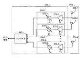
図5Bは、指向性受信用の指向性受信ビームを使用して信号を受信するように構成された受信ビームフォーマー555およびアンテナアレイ552の一例を示す。アンテナアレイ552は、複数のアンテナ550-1〜550-Kを備える。ビームフォーマー555は、信号コンバイナ580および複数の分岐558-1〜558-Kを備え、ここで、各分岐558-1〜558-Kは、アンテナ550-1〜550-Kのうちのそれぞれのアンテナに結合されている。各分岐558-1〜558-Nは、それぞれの調整可能な移相器570-1〜570-Kおよびそれぞれの調整可能な増幅器575-1〜575-Kをさらに備え得る。各移相器570-1〜570-Kの位相シフトは、それぞれの位相シフト制御信号P1〜PKによって制御され、各増幅器575-1〜575-Kの利得は、それぞれの利得制御信号G1〜GKによって制御される。
FIG. 5B shows an example of a receive
動作においては、分岐558-1〜558-Kの各々が、それぞれのアンテナ550-1〜550-Kから信号を受信する。各移相器570-1〜570-Kは、それぞれの分岐における信号の位相をそれぞれの位相シフト制御信号P1〜PKに従ってシフトさせ、各増幅器575-1〜575-Kは、それぞれの分岐における信号をそれぞれの利得制御信号G1〜GKに従って増幅する。各分岐518-1〜518-Kの出力信号は、信号コンバイナ580に供給され、信号コンバイナ580は、信号を合成して出力信号にする。分岐の相対的な位相および振幅は、指向性受信ビーム内の受信感度を高め、ここで、受信ビームの方向は、ビームフォーマー555に入力される位相シフト制御信号P1〜PKおよび利得制御信号G1〜GKの関数である。
In operation, each of the branches 558-1 to 558-K receives a signal from a respective antenna 550-1 to 550-K. Each phase shifter 570-1 to 570-K shifts the phase of the signal in its respective branch according to its respective phase shift control signal P 1 to P K , and each amplifier 575-1 to 575-K has its respective branch Is amplified according to the respective gain control signals G 1 to G K. The output signals of the respective branches 518-1 to 518-K are supplied to the
一例では、ビームフォーマー555およびアンテナアレイ552は、指向性受信用に図2におけるアクセスポイント110の中に実装され得る。この例では、アンテナ550-1〜550-Kは、図2におけるアンテナ230-1〜230-N、またはアンテナ230-1〜230-Nのサブセットに相当し得、ビームフォーマー555は、図2における受信プロセッサ242、および/またはトランシーバ226-1〜226-N、もしくはトランシーバ226-1〜226-Nのサブセットの中に実装され得る。したがって、コントローラ234は、位相シフト制御信号P1〜PKおよび利得制御信号G1〜GKの値を制御することによって、受信ビームの方向を制御し得る。この点について、コントローラ234は、複数のビーム方向のうちの各ビーム方向に対して、位相シフト値および利得値(たとえば、重みベクトル)のセットをメモリ236に記憶し得る。この例では、コントローラ234は、位相シフト値および利得値の対応するセットをメモリ236から取り出し、それに応じてビームフォーマー555の位相シフトおよび利得を設定することによって、特定の方向に受信ビームを配向させ得る。ビームフォーマー555およびアンテナアレイ552はまた、指向性受信用にアクセス端末120の中に同様の方法で実装され得る。
In one example,
本開示の実施形態が図5Bにおける例示的なビームフォーマー555およびアンテナアレイ552に限定されないことを諒解されたい。たとえば、信号は、複数の指向性アンテナを使用して異なる方向に受信されてよく、その場合、各アンテナ方向は、異なる方向に信号を受信するように構成される。指向性受信ビームはまた、フェーズドアンテナアレイと指向性アンテナとの組合せを使用して実装されてもよい。
It should be appreciated that embodiments of the present disclosure are not limited to the
ワイヤレスノード(たとえば、アクセスポイント110またはアクセス端末120)がまた、オムニ指向性モードおよび上記で説明した指向性モードで信号を受信および送信してよいことも諒解されたい。たとえば、信号が、2つ以上のワイヤレスノードによって受信されるように意図されるとき、またはワイヤレスノードが、意図された受信ワイヤレスノードの方向を知らないとき、ワイヤレスノードは、オムニ指向性モードで信号を送信してよい。別の例では、送信しているワイヤレスノードの方向をワイヤレスノードが知らないとき、ワイヤレスノードは、オムニ指向性モードで信号を受信してよい。ワイヤレスノードは、オムニ指向性アンテナを使用して、かつ/またはオムニ指向性ビームで送信および受信するように複数のアンテナを動作させて、オムニ指向性モードで動作してよい。
It should also be appreciated that a wireless node (eg,
いくつかの態様では、通信システム100は、容量を増大させ、かつ/または干渉を低減するために、偏波ダイバーシティを使用する。たとえば、偏波ダイバーシティにより、ワイヤレスノードに異なる偏波を使用して信号を送信させることによって、極めて近接したワイヤレスノードが、同じ周波数を再使用して容量を増大させることが可能になり得る。一例では、ワイヤレスノードは、異なる直線偏波を使用する送信および受信をサポートし得る。直線偏波は、互いに直交している水平偏波および垂直偏波を含み得る。別の例では、ワイヤレスノードは、異なる円偏波を使用する送信および受信をサポートし得る。円偏波は、右旋円偏波および左旋円偏波を含み得、ここで、右旋円偏波を使用して送信される信号は、左旋円偏波を使用して送信される信号とは反対方向に回転する。また別の例では、ワイヤレスノードは、より強い偏波ダイバーシティを得るために、異なる円偏波および直線偏波を使用する送信および受信をサポートし得る。
In some aspects, the
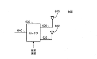
図6は、本開示のいくつかの態様による、異なる偏波を使用して信号を送信および/または受信するように構成されたアンテナデバイス605の一例を示す。アンテナデバイス605は、図2におけるアンテナ230-1〜230-Nおよび270-1〜270-Nの各々、または図2におけるアンテナのサブセットの各々を実装するために使用され得る。アンテナデバイス605は、第1のアンテナ素子610、第2のアンテナ素子612、および偏波セレクタ630を備え得る。セレクタ630は、第1の給電線路620を介して第1のアンテナ素子610に結合され得、第2の給電線路622を介して第2のアンテナ素子612に結合され得、メイン給電線路640を介してトランシーバ(たとえば、トランシーバ226または266)に結合され得る。第1のアンテナ素子610および第2のアンテナ素子612の各々は、異なる偏波を使用して信号を送信および/または受信するように構成され得る。たとえば、直線偏波の場合、第1のアンテナ素子610は、水平偏波を使用して信号を送信および/または受信するように構成されてよく、第2のアンテナ素子612は、水平偏波に直交する垂直偏波を使用して信号を送信および/または受信するように構成されてよい。別の例では、円偏波の場合、第1のアンテナ素子610は、右旋円偏波を使用して信号を送信および/または受信するように構成されてよく、第2のアンテナ素子612は、左旋円偏波を使用して信号を送信および/または受信するように構成されてよい。
FIG. 6 illustrates an
動作においては、セレクタ630は、第1のアンテナ素子610および第2のアンテナ素子612によってサポートされる2つの偏波のうちの選択された偏波を示す偏波選択信号を受信する。セレクタ630は、次いで、選択された偏波に基づいて、メイン給電線路640を第1のアンテナ素子610または第2のアンテナ素子612に結合させる。したがって、セレクタ630により、アンテナデバイス605が選択信号に基づいて2つの偏波の間で切り替えることが可能になる。いくつかの態様では、以下でさらに説明するように、コントローラ234または274は、コントローラ234または247が偏波を選択することを可能にするための選択信号を生成し得る。上記で説明したように、アンテナ230-1〜230-Nまたは270-1〜270-Nの各々は、アンテナデバイス605を使用して実装され得る。この態様では、コントローラ234または274は、偏波選択信号を各アンテナに出力することによって各アンテナの偏波を制御し得る。
In operation, the
図6におけるアンテナデバイス605が2つの異なる偏波に限定されないことを諒解されたい。たとえば、アンテナデバイス605は、第1および第2のアンテナ素子の偏波とは異なる偏波を有する追加のアンテナ素子を備えてよい。この例では、セレクタ630は、アンテナ素子(すなわち、第1および第2のアンテナ素子ならびに追加のアンテナ素子)のうちのいずれか1つを、アンテナ素子によってサポートされる偏波のうちのいずれか1つを選択するための偏波選択信号に従って選択し得る。
It should be appreciated that the
第1のアンテナ素子610および第2のアンテナ素子612は、異なる偏波を実現するための様々な異なるアンテナ構造のうちのいずれか1つを使用して実装され得る。たとえば、直線偏波の場合、第1のアンテナ素子610および第2のアンテナ素子612は、互いに直交に配向されている2つのダイポールアンテナ素子を使用して実装され得る。別の例では、円偏波の場合、第1のアンテナ素子610および第2のアンテナ素子612は、反対方向にらせん状になる2つのスパイラルアンテナ素子を使用して実装され得る。また別の例では、第1のアンテナ素子610および第2のアンテナ素子612の各々は、接地面の上に金属層を備えるパッチアンテナを使用して実装され得る。この例では、アンテナ素子の金属層は、アンテナ素子にとって所望の偏波を実現するために、1つまたは複数のU字形スロット、1つまたは複数のL字形スロット、1つまたは複数のT字形スロット、および/あるいは1つまたは複数の他の形状のスロットを有し得る。第1のアンテナ素子610および第2のアンテナ素子612が、上記で与えられた例に限定されず、他のアンテナ構造を使用して実装され得ることを諒解されたい。
The
いくつかの態様では、ワイヤレスノードにおける干渉を低減するために、偏波ダイバーシティが活用される。この点について、図7Aは、図4における第1のワイヤレスノード410が第3のワイヤレスノード430からの干渉710を受ける例を示す。干渉710は、第4のワイヤレスノード(図示せず)に宛てられている(アドレス指定されている)信号を備えることがあり、したがって、第1のワイヤレスノード410に対する干渉信号である。この例では、第1のワイヤレスノード410は、干渉710のフレーム(パケットとも呼ばれる)の中の宛先アドレスを検出および復号し、宛先アドレスが第1のワイヤレスノード410以外のワイヤレスノードに対応する(すなわち、宛先アドレスが第1のワイヤレスノード410のアドレスに一致しない)と決定することによって、干渉710を検出し得る。宛先アドレスは、フレームのアドレスフィールドの中で見つけられてよい。別の例では、第1のワイヤレスノード410は、第1のワイヤレスノード410が第2のワイヤレスノード420からの送信を受信していない時間中に受信電力を測定することによって、干渉を検出し得る。この例では、第1のワイヤレスノード410は、受信電力がいくらかのしきい値を上回るとき、干渉を検出する。
In some aspects, polarization diversity is exploited to reduce interference at the wireless node. In this regard, FIG. 7A shows an example in which the
図7Aは、簡単にするために1つの干渉源(すなわち、第3のワイヤレスノード430)しか示さないが、第1のワイヤレスノード410が追加の干渉源(たとえば、通信システムにおける他のワイヤレスノード)からの干渉を受信し得ることを諒解されたい。第1のワイヤレスノード410は、上記で説明した技法のいずれかを使用して各干渉源からの干渉を検出し得る。
FIG. 7A shows only one interference source (i.e., third wireless node 430) for simplicity, but the
干渉710を検出した後、第1のワイヤレスノード410は、第1のワイヤレスノード410によってサポートされる複数の偏波のうちのどの偏波が第1のワイヤレスノード410における干渉710を最小限に抑えるのかを決定し得る。たとえば、第1のワイヤレスノード410は、オムニ指向性ビーム712を使用して、オムニ指向性モードにおける偏波の各々に対して干渉710の強度を測定し得る。この例では、コントローラ234または274は、第1のワイヤレスノード410を偏波の各々に切り替える。偏波の各々に対して、受信プロセッサ242または282は、第1のワイヤレスノード410における干渉710の強度を測定し得る。干渉710の測定強度は、干渉710の振幅、エネルギー、および/または電力を示す任意の測定値であり得る。いくつかの態様では、受信プロセッサ242または282はまた、偏波の各々に対して第2のワイヤレスノード420または他のターゲットノードからの信号の強度を測定し得、干渉710の強度に対する信号の強度(たとえば、信号対干渉雑音比(SINR))を決定し得る。
After detecting the
偏波の各々に対して干渉710の強度を測定した後、コントローラ234または247は、干渉710の測定強度が最小であるかまたはSINRが最大である偏波を選択し得る。コントローラ234または247は、次いで、以下でさらに説明するように、選択された偏波を後で使用できるようにメモリ236または276に記憶し得る。
After measuring the intensity of the
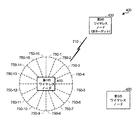
図7Bは、第1のワイヤレスノード410が指向性モードにおける偏波の各々に対して干渉710の強度を測定する別の例を示す。この例では、コントローラ234または274は、第1のワイヤレスノード410を複数の異なる指向性受信ビーム750-1〜750-16のうちの各指向性受信ビームに切り替え得る。受信ビーム750-1〜750-16の各々に対して、コントローラ234または274は、第1のワイヤレスノード410を偏波の各々に切り替えてよく、偏波の各々に対して干渉710の強度および/またはSINRを測定し得る。
FIG. 7B shows another example in which the
受信ビーム750-1〜750-16の各々に対して、コントローラ234または274は、干渉710の強度が受信ビームにとって最小であるかまたはSINRが受信ビームにとって最大である偏波を選択し得る。コントローラ234または247は、次いで、以下でさらに説明するように、受信ビーム750-1〜750-16の各々に対して選択された偏波を後で使用できるようにメモリ236または276に記憶し得る。選択された偏波の各々に対して、コントローラ234または247はまた、対応する受信ビームを示すインジケータを記憶し得る。
For each of the receive beams 750-1 through 750-16, the
本開示の態様が図7Bに示す例示的な受信ビーム750-1〜750-16に限定されないことを諒解されたい。たとえば、第1のワイヤレスノード410は、任意の数の受信ビームを有してよく、様々な幅および形状の受信ビームを有してよい。第1のワイヤレスノード410がまた、オーバーラップする受信ビームを有してよいことも諒解されたい。
It should be appreciated that aspects of the present disclosure are not limited to the exemplary receive beams 750-1 through 750-16 illustrated in FIG. 7B. For example, the
したがって、受信ビーム715-1〜750-16の各々に対して、第1のワイヤレスノード410は、受信ビームにとって最小の干渉強度または最大のSINRをもたらす偏波を選択し得、ビームごとに選択偏波をメモリに記憶し得る。第2のワイヤレスノード420も、最小の干渉強度または最大のSINRをもたらす、異なるビームに対する偏波を選択するために上記のステップを実行し得ることを諒解されたい。
Thus, for each of the receive beams 715-1 through 750-16, the
上記で説明したように、干渉710は、第1のワイヤレスノード410以外のワイヤレスノード(図示せず)にアドレス指定されたフレーム(パケットとも呼ばれる)を備え得る。この例では、第1のワイヤレスノード410は、フレームの中のアドレスを受信および復号し、アドレスが第1のワイヤレスノード410のアドレスに一致しない場合に干渉を検出することによって、干渉710を検出し得る。干渉が検出される場合、第1のワイヤレスノード410は、フレームの中の持続時間フィールドを受信および復号して、フレームの持続期間を決定し得る。第1のワイヤレスノード410は、次いで、決定された持続期間内で、上記で説明したように、異なるビームおよび偏波における干渉を受信および測定し得る。
As described above, the
異なるビームに対して偏波を選択した後、第1のワイヤレスノード410は、第2のワイヤレスノード420との通信に対して偏波を選択する際にこの情報を使用し得る。たとえば、第1のワイヤレスノード410は、第2のワイヤレスノード420からの送信を(たとえば、ビームトレーニング手順の間に)受信するために、受信ビーム750-1〜750-16のうちの1つを選択し得る。このことの一例が図8に示され、ここで、第1のワイヤレスノード410は、この例では、第2のワイヤレスノード420のほうへ向けられている受信ビーム750-5を選択する。受信ビーム750-5を選択した後、第1のワイヤレスノード410は、受信ビーム750-5に対して選択された偏波を使用して、第2のワイヤレスノード420からの通信を受信する。第1のワイヤレスノード410は、たとえば、受信ビーム750-5に対して選択された偏波をメモリから取り出すことによってこのことを行ってよい。
After selecting the polarization for the different beams, the
別の例では、第1のワイヤレスノード410は、(たとえば、送信しているワイヤレスノードの方向を第1のワイヤレスノード410が知らないとき)オムニ指向性モードで信号を受信してよい。この例では、第1のワイヤレスノード410は、オムニ指向性モードに対して選択された偏波を使用して、オムニ指向性モードで送信を受信する。第1のワイヤレスノード410は、たとえば、オムニ指向性モードに対する偏波をメモリから取り出すことによってこのことを行ってよい。
In another example, the
また別の例では、第1のワイヤレスノード410は、第2のワイヤレスノード420のほうへ向けられている送信ビームを使用して、第2のワイヤレスノード420へ信号を送信し得る。送信ビームは、図8における受信ビーム750-5と類似の形状を有してよく、かつ/またはほぼ同じ方向を(すなわち、第2のワイヤレスノード420のほうを)指してよい。この例では、第1のワイヤレスノード410は、受信ビーム750-5に対して選択された偏波を送信ビームに対して使用してよい。このことは、受信ビームに対して選択された偏波が、対応する送信ビーム(たとえば、類似の形状を有し、かつ/またはほぼ同じ方向を指す送信ビーム)に対しても干渉の低減をもたらすものと想定される、受信と送信との相反性に基づき得る。たとえば、受信ビームおよび送信ビームが同じアンテナアレイ(たとえば、アンテナ230-1〜230-Nまたはアンテナ270-1〜270-N)を使用して形成されるとき、この想定は有効であり得る。
In yet another example, the
図9は、本開示のいくつかの態様による偏波を選択するための方法900を示すフローチャートである。方法900は、ワイヤレスノード(たとえば、第1のワイヤレスノード410)によって実行され得る。
FIG. 9 is a flowchart illustrating a
ステップ910において、2つ以上の偏波のうちの各偏波において、少なくとも1つの干渉源からの干渉が受信される。たとえば、干渉は、別のワイヤレスノードにアドレス指定された信号を備え得る。2つ以上の偏波は、以下のもの、すなわち、水平偏波、垂直偏波、右旋円偏波、および左旋円偏波のうちの2つ以上を備え得る。一例では、干渉は、オムニ指向性ビームを使用して受信され得る。別の例では、干渉は、指向性受信ビームを使用して受信され得る。この例では、指向性受信ビームは、リモートデバイスの既知の方向に基づいて選択されてよく、ここで、方向は、リモートデバイスとの以前のビームトレーニング、そのロケーションを示すリモートデバイスからの信号などから知られていてよい。
In
ステップ920において、2つ以上の偏波のうちの各偏波において、受信された干渉の強度が測定される。たとえば、受信された干渉の強度は、干渉の振幅、電力、および/またはエネルギーを測定することによって偏波ごとに測定され得る。別の例では、各偏波における干渉の強度は、信号に対してSINRの形態で測定され得る。
In
ステップ930において、測定強度に基づいて2つ以上の偏波のうちの1つが選択される。たとえば、最小の測定干渉強度または最大のSINRに対応する偏波が選択され得る。
In
ステップ940において、2つ以上の偏波のうちの選択された偏波は、リモートデバイスと通信するために使用される。たとえば、通信は、選択された偏波を使用してリモートデバイス(たとえば、第2のワイヤレスノード420)からの信号を受信することを含み得る。ステップ910において、指向性受信ビームを使用して干渉が受信される場合、指向性受信ビームを使用してリモート局から信号が受信され得る。別の例では、通信は、受信と送信との相反性を想定して、選択された偏波を使用してリモートデバイスへ信号を送信することを含み得る。ステップ910において、指向性受信ビームを使用して干渉が受信される場合、受信ビームと類似の形状を有しかつ/または受信ビームとほぼ同じ方向を指す指向性送信ビームを使用して、リモートデバイスへ信号が送信され得る。
In
いくつかの態様では、ステップ910〜930は、受信ビームの各々に対して偏波を選択するために、複数の受信ビーム(たとえば、受信ビーム750-1〜750-16、または受信ビーム750-1〜750-16のサブセット)のうちの各受信ビームに対して実行され得る。これらの態様では、ビームトレーニングまたは他の方法を使用して、受信ビームのうちの1つがリモートデバイス(たとえば、第2のワイヤレスノード420)との通信に対して選択され得る。受信ビームが選択されると、選択された受信ビームおよび対応する選択された偏波は、リモートデバイスからの信号を受信するために使用され得る。 In some aspects, steps 910-930 include a plurality of receive beams (eg, receive beams 750-1 to 750-16, or receive beams 750-1 to select a polarization for each of the receive beams. ˜750-16 subset) for each received beam. In these aspects, using beam training or other methods, one of the received beams may be selected for communication with a remote device (eg, second wireless node 420). Once the receive beam is selected, the selected receive beam and the corresponding selected polarization can be used to receive signals from the remote device.
上記で説明したように、図8における受信ビーム750-5および送信ビーム422が、ビームトレーニング手順を使用して選択され得る。この点について、いくつかの態様による例示的なビームトレーニング手順が、ここで、図10Aおよび図10Bを参照しながら説明される。この例では、ビームトレーニング手順は2つの段階を備えてよく、以下でさらに説明するように、送信ビームは第1の段階において決定され、受信ビームは第2の段階において決定される。
As explained above, receive beam 750-5 and transmit
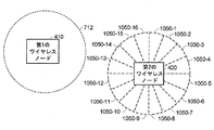
図10Aを参照すると、ビームトレーニング手順の第1の段階の間、第2のワイヤレスノード420は、複数の指向性送信ビーム1050-1〜1050-16を使用してビームトレーニング信号を送信する。送信ビーム1050-1〜1050-16の各々に対して、第2のワイヤレスノード420は、複数の偏波のうちの各偏波に対してビームトレーニング信号を送信し得る。各ビームトレーニング信号は、トレーニングシーケンス(たとえば、コードシーケンス)、トレーニングパケットなどを備え得る。したがって、第2のワイヤレスノード420は、送信ビーム1050-1〜1050-16を通じてスイープし得、ここで、第2のワイヤレスノード420は、送信ビームごとに異なる偏波を使用してビームトレーニング信号を送信し得る。
Referring to FIG. 10A, during the first phase of the beam training procedure, the
第1のワイヤレスノード410は、上記で説明したオムニ指向性モードに対して選択された偏波を使用して、オムニ指向性モードでビームトレーニング信号のうちの1つまたは複数を受信してよい。ビームトレーニング信号を受信するために選択された偏波を使用することによって、第1のワイヤレスノード410は、選択された偏波をビームトレーニング手順に組み込む。受信されたビームトレーニング信号の各々に対して、第1のワイヤレスノード410は、ビームトレーニング信号の強度(たとえば、信号の信号対雑音比(SNR)、受信信号強度インジケータ(RSSI)など)を測定し得る。
The
第1のワイヤレスノード410は、次いで、受信されたビームトレーニング信号が最大の強度を有すると決定し得、決定されたビームトレーニング信号を識別するフィードバックメッセージを第2のワイヤレスノード420へ送信し得る。第1のワイヤレスノード410は、様々な技法のうちのいずれか1つを使用して、決定されたビームトレーニング信号を識別し得る。たとえば、各ビームトレーニング信号は、第1のワイヤレスノード410によって検出および復号され得る固有の識別子を含んでよい。この例では、第1のワイヤレスノード410は、決定されたビームトレーニング信号の識別子をメッセージの中に含め得る。別の例では、第1のワイヤレスノード410は、ビームトレーニング信号が受信された時間、および/または決定されたビームトレーニング信号が受信された順序に基づいて、決定されたビームトレーニング信号を識別し得る。したがって、第1のワイヤレスノード410は、第1のワイヤレスノード410において最大の受信信号強度をもたらすビームトレーニング信号において、フィードバックを第2のワイヤレスノード420に提供し得る。
The
フィードバックメッセージを受信すると、第2のワイヤレスノード420は、メッセージの中で示されるビームトレーニング信号に対応する送信ビームおよび偏波を決定する。言い換えれば、第2のワイヤレスノード420は、メッセージの中で示されるビームトレーニング信号を送信するために使用された送信ビームおよび偏波を決定する。第2のワイヤレスノード420は、第1のワイヤレスノード410への後続の送信に対して、決定された送信ビームおよび偏波を使用する。したがって、送信ビームは、ビームトレーニング手順の第1の段階の間に選択される。図10Aに示す例では、送信ビーム1050-13が選択される。
Upon receiving the feedback message, the
図10Bを参照すると、ビームトレーニング手順の第2の段階の間、第2のワイヤレスノード420は、第1の段階において決定された送信ビームおよび偏波を使用して複数のビームトレーニング信号を送信する。第1のワイヤレスノード410は、受信ビーム(たとえば、受信ビーム750-1〜750-16、または受信ビーム750-1〜750-16のサブセット)のうちの異なる受信ビームを使用して各ビームトレーニング信号を受信し得る。受信ビームごとに、第1のワイヤレスノード410は、それぞれのビームトレーニング信号を受信するために、受信ビームに対して選択された偏波を使用し得る。
Referring to FIG. 10B, during the second phase of the beam training procedure, the
ビームトレーニング信号ごとに、第1のワイヤレスノード410は、ビームトレーニング信号の強度(たとえば、SNR、RSSIなど)を測定し得る。ビームトレーニング信号の強度を測定した後、第1のワイヤレスノード410は、強度が最大のビームトレーニング信号を決定し得、信号強度が最大のビームトレーニング信号に対応する受信ビームを選択し得る。図10Bにおける例では、受信ビーム750-5が選択される。第1のワイヤレスノード410は、第2のワイヤレスノード420からの送信を受信するために、選択された受信ビームおよび対応する偏波を使用し得る。
For each beam training signal, the
したがって、上記の例におけるビームトレーニング手順は、第2のワイヤレスノード420から第1のワイヤレスノード410への送信に対して送信ビームおよび受信ビームを選択し、ここで、送信ビームは第1の段階においてトレーニングされ、受信ビームは第2の段階においてトレーニングされる。同じビームトレーニング手順がまた、第1のワイヤレスノード410から第2のワイヤレスノード420への送信に対して送信ビームおよび受信ビームを選択するために使用されてよく、その場合、第1および第2のワイヤレスノードの役割は逆になる。
Thus, the beam training procedure in the above example selects a transmit beam and a receive beam for transmission from the
トレーニング時間を短くするために、第2のワイヤレスノード420が、ビームトレーニング手順の間、第2のワイヤレスノード420によってサポートされる送信ビームのサブセットを通じてスイープしてよいことを諒解されたい。たとえば、第2のワイヤレスノード420は、第1のワイヤレスノード410の概略的な方向を(たとえば、以前のビームトレーニング、第1のワイヤレスノード410に対するロケーション情報などから)知っていることがある。この例では、第2のワイヤレスノード420は、既知の概略的な方向に近い方向を指す送信ビームのサブセットまでスイープを狭くしてよい。
It should be appreciated that the
トレーニング時間を短くするために、第1のワイヤレスノード410が、ビームトレーニング手順の間、第1のワイヤレスノード410によってサポートされる受信ビームのサブセットを通じてスイープしてよいことも諒解されたい。たとえば、第1のワイヤレスノード410は、第2のワイヤレスノード420の概略的な方向を(たとえば、以前のビームトレーニング、第2のワイヤレスノード420に対するロケーション情報などから)知っていることがある。この例では、第1のワイヤレスノード410は、既知の概略的な方向に近い方向を指す受信ビームのサブセットまでスイープを狭くしてよい。
It should also be appreciated that to reduce training time, the
本開示の実施形態が、上記で説明した例示的なビームトレーニング手順に限定されないこと、および他のビームトレーニング手順において使用され得ることを諒解されたい。 It should be appreciated that embodiments of the present disclosure are not limited to the exemplary beam training procedures described above and can be used in other beam training procedures.
図11は、本開示のいくつかの態様による例示的なデバイス1100を示す。デバイス1100は、ワイヤレスノード(たとえば、アクセスポイント110またはアクセス端末120)において動作するとともに、本明細書で説明する動作のうちの1つまたは複数を実行するように構成され得る。デバイス1100は、処理システム1120、およびプロセッサシステム1120に結合されたメモリ1110を含む。メモリ1110は、処理システム1120によって実行されたとき、本明細書で説明する動作のうちの1つまたは複数を処理システム1120に実行させる命令を記憶し得る。処理システム1120の例示的な実装形態が以下に提供される。デバイス1100はまた、処理システム1120に結合された送信/受信機インターフェース1130を備える。インターフェース1130(たとえば、インターフェースバス)は、処理システム1120を無線周波数(RF)フロントエンド(たとえば、トランシーバ226-1〜226-Nまたは266-1〜266-N)にインターフェースするように構成され得る。
FIG. 11 illustrates an
いくつかの態様では、処理システム1120は、以下のもの、すなわち、本明細書で説明する動作のうちの1つもしくは複数を実行するための、送信データプロセッサ(たとえば、送信データプロセッサ220または260)、フレームビルダー(たとえば、フレームビルダー222または262)、送信プロセッサ(たとえば、送信プロセッサ224または264)、および/またはコントローラ(たとえば、コントローラ234または274)のうちの1つまたは複数を含み得る。
In some aspects, the
アクセス端末120の場合には、デバイス1100は、処理システム1120に結合されたユーザインターフェース1140を含み得る。ユーザインターフェース1140は、ユーザから(たとえば、キーパッド、マウス、ジョイスティックなどを介して)データを受信するとともに、データを処理システム1120に提供するように構成され得る。ユーザインターフェース1140はまた、処理システム1120からユーザに(たとえば、ディスプレイ、スピーカーなどを介して)データを出力するように構成され得る。この場合、データは、ユーザに出力される前に追加の処理を受けることがある。アクセスポイント110の場合には、ユーザインターフェース1140は省略されてよい。
In the case of
本明細書で使用するとき、装置における「干渉」は、1つまたは複数の他の装置に宛てられている1つまたは複数の信号を含み得る。たとえば、1つまたは複数の信号は、1つまたは複数の他の装置にアドレス指定された1つまたは複数のフレーム(パケット)を含み得る。この例では、1つまたは複数の信号は装置に宛てられている信号と干渉し得るので、1つまたは複数の信号は、装置に対する干渉となり得る。干渉は、装置と同じ通信システム(たとえば、ネットワーク)における1つまたは複数の他の装置(たとえば、ワイヤレスノード)によって送信された、装置における不要な信号を備えることがある。干渉はまた、別の通信システムにおける1つまたは複数の他の装置によって送信された、装置における不要な信号を備えることがあり、ここで、他の通信システムは、装置の通信システムによって使用される周波数帯域にオーバーラップする周波数帯域を使用することがある。干渉はまた、1つまたは複数の他の装置および/または装置の中の構成要素からのRF放射を備えることがある。 As used herein, “interference” in a device may include one or more signals that are addressed to one or more other devices. For example, the one or more signals may include one or more frames (packets) addressed to one or more other devices. In this example, the one or more signals can interfere with the signal destined for the device, so the one or more signals can interfere with the device. The interference may comprise unwanted signals at the device transmitted by one or more other devices (eg, wireless nodes) in the same communication system (eg, network) as the device. Interference may also comprise unwanted signals at a device transmitted by one or more other devices in another communication system, where the other communication system is used by the communication system of the device. A frequency band that overlaps the frequency band may be used. The interference may also comprise RF radiation from one or more other devices and / or components within the devices.
アンテナ230-1〜230-Nおよび270-1〜270-N、アンテナデバイス605、送信/受信インターフェース1130、トランシーバ226-1〜226-Nおよび266-1〜266-N、ならびにビームフォーマー515および555は、2つ以上の偏波のうちの偏波の各々において、干渉を受信するための手段の例である。受信プロセッサ242および282、コントローラ234および274、ならびに処理システム1120は、2つ以上の偏波のうちの各偏波において、受信された干渉の強度を測定するための手段、および測定干渉強度に基づいて2つ以上の偏波のうちの1つを選択するための手段の例である。アンテナ230-1〜230-Nおよび270-1〜270-N、アンテナデバイス605、送信/受信インターフェース1130、トランシーバ226-1〜226-Nおよび266-1〜266-N、ならびにビームフォーマー515および555は、2つ以上の偏波のうちの選択された偏波を使用してリモートデバイスと通信するための手段の例である。受信プロセッサ242および282、コントローラ234および274、ならびに処理システム1120は、測定干渉強度のうちの最小の測定干渉強度に対応する、2つ以上の偏波のうちの1つを選択するための手段の例である。受信プロセッサ242および282、コントローラ234および274、ならびに処理システム1120は、それぞれの測定干渉強度に基づいて信号対干渉雑音比(SINR)を決定するための手段、およびSINRのうちの最大のSINRに対応する、2つ以上の偏波のうちの1つを選択するための手段の例である。アンテナ230-1〜230-Nおよび270-1〜270-N、アンテナデバイス605、送信/受信インターフェース1130、トランシーバ226-1〜226-Nおよび266-1〜266-N、ならびにビームフォーマー515および555は、少なくとも1つのフレームの中で少なくとも1つの宛先アドレスフィールドを受信するための手段の例である。受信プロセッサ242および282、コントローラ234および274、ならびに処理システム1120は、フレームの少なくとも1つの宛先アドレスを決定するために、少なくとも1つの宛先アドレスフィールドを復号するための手段、装置のアドレスが少なくとも1つの宛先アドレスに一致するかどうかを決定するための手段、および装置のアドレスが少なくとも1つの宛先アドレスに一致しない場合に干渉を検出するための手段の例である。アンテナ230-1〜230-Nおよび270-1〜270-N、アンテナデバイス605、送信/受信インターフェース1130、トランシーバ226-1〜226-Nおよび266-1〜266-N、ならびにビームフォーマー515および555は、少なくとも1つのフレームの中で少なくとも1つの持続時間フィールドを受信するための手段の例である。受信プロセッサ242および282、コントローラ234および274、ならびに処理システム1120は、干渉の持続時間を決定するために、少なくとも1つの持続時間フィールドを復号するための手段の例である。アンテナ230-1〜230-Nおよび270-1〜270-N、アンテナデバイス605、送信/受信インターフェース1130、トランシーバ226-1〜226-Nおよび266-1〜266-N、ならびにビームフォーマー515および555は、2つ以上の偏波のうちの選択された偏波において、リモートデバイスからの複数の信号を受信するための手段の例である。受信プロセッサ242および282、コントローラ234および274、ならびに処理システム1120は、複数の信号のうちの信号の各々の強度を測定するための手段、および複数の信号のうちの1つを選択するための手段の例である。アンテナ230-1〜230-Nおよび270-1〜270-N、アンテナデバイス605、送信/受信インターフェース1130、トランシーバ226-1〜226-Nおよび266-1〜266-N、ならびにビームフォーマー515および555は、複数の信号のうちの選択された信号を示すメッセージをリモートデバイスへ送信するための手段の例である。
Antennas 230-1 to 230-N and 270-1 to 270-N,
上記で説明した方法の様々な動作は、対応する機能を実行することが可能な任意の好適な手段によって実行され得る。手段は、限定はしないが、回路、特定用途向け集積回路(ASIC)、またはプロセッサを含む、様々なハードウェアおよび/またはソフトウェア構成要素および/またはモジュールを含み得る。概して、図に示される動作がある場合、それらの動作は、類似の番号を伴う対応する同等のミーンズプラスファンクション構成要素を有し得る。 Various operations of the methods described above may be performed by any suitable means capable of performing the corresponding function. The means may include various hardware and / or software components and / or modules, including but not limited to circuits, application specific integrated circuits (ASICs), or processors. In general, if there are operations shown in the figures, those operations may have corresponding equivalent means plus function components with similar numbers.
場合によっては、デバイスは、実際にフレームを送信するのではなく、送信のためにフレームを出力するインターフェース(出力するための手段)を有し得る。たとえば、プロセッサは、バスインターフェースを介して、送信のためにフレームを無線周波数(RF)フロントエンドに出力し得る。同様に、デバイスは、実際にフレームを受信するのではなく、別のデバイスから受信されたフレームを取得するためのインターフェース(取得するための手段)を有し得る。たとえば、プロセッサは、バスインターフェースを介して、受信のためにRFフロントエンドからフレームを取得(または、受信)し得る。 In some cases, the device may have an interface (means for outputting) that outputs the frame for transmission rather than actually transmitting the frame. For example, the processor may output the frame to a radio frequency (RF) front end for transmission over the bus interface. Similarly, a device may have an interface (means for obtaining) to obtain a frame received from another device rather than actually receiving a frame. For example, the processor may obtain (or receive) a frame from the RF front end for reception via the bus interface.
本明細書で使用する「決定すること」という用語は、多種多様なアクションを包含する。たとえば、「決定すること」は、計算すること、算出すること、処理すること、導出すること、調査すること、ルックアップすること(たとえば、テーブル、データベース、または別のデータ構造の中でルックアップすること)、確認することなどを含み得る。また、「決定すること」は、受信すること(たとえば、情報を受信すること)、アクセスすること(たとえば、メモリの中のデータにアクセスすること)などを含み得る。また、「決定すること」は、解決すること、選択すること、選ぶこと、確立することなどを含み得る。 As used herein, the term “determining” encompasses a wide variety of actions. For example, “determining” means calculating, calculating, processing, deriving, examining, looking up (eg, looking up in a table, database, or another data structure) ), Confirmation, etc. Also, “determining” can include receiving (eg, receiving information), accessing (eg, accessing data in a memory) and the like. Also, “determining” can include resolving, selecting, choosing, establishing and the like.
本明細書で使用するとき、項目のリスト「のうちの少なくとも1つ」を指す句は、単一のメンバーを含むそれらの項目の任意の組合せを指す。一例として、「a、b、またはcのうちの少なくとも1つ」は、a、b、c、a-b、a-c、b-c、およびa-b-c、ならびに複数の同じ要素を有する任意の組合せ(たとえば、a-a、a-a-a、a-a-b、a-a-c、a-b-b、a-c-c、b-b、b-b-b、b-b-c、c-c、およびc-c-c、または任意の他の順序のa、b、およびc)を包含するように意図される。 As used herein, a phrase referring to “at least one of” a list of items refers to any combination of those items including a single member. By way of example, “at least one of a, b, or c” includes a, b, c, ab, ac, bc, and abc, and any combination having a plurality of the same elements (eg, aa, aaa , Aab, aac, abb, acc, bb, bbb, bbc, cc, and ccc, or any other order of a, b, and c).
本開示に関して説明した様々な例示的な論理ブロック、モジュール、および回路は、汎用プロセッサ、デジタル信号プロセッサ(DSP)、特定用途向け集積回路(ASIC)、フィールドプログラマブルゲートアレイ(FPGA)もしくは他のプログラマブル論理デバイス(PLD)、個別ゲートもしくはトランジスタ論理、個別ハードウェア構成要素、または本明細書で説明した機能を実行するように設計されたそれらの任意の組合せを用いて実装または実行され得る。汎用プロセッサは、マイクロプロセッサであってよいが、代替として、プロセッサは、任意の市販のプロセッサ、コントローラ、マイクロコントローラ、またはステートマシンであってもよい。プロセッサはまた、コンピューティングデバイスの組合せ、たとえば、DSPとマイクロプロセッサとの組合せ、複数のマイクロプロセッサ、DSPコアと連携した1つもしくは複数のマイクロプロセッサ、または任意の他のそのような構成として実装されてよい。 Various exemplary logic blocks, modules, and circuits described with respect to this disclosure may be general purpose processors, digital signal processors (DSPs), application specific integrated circuits (ASICs), field programmable gate arrays (FPGAs), or other programmable logic. It may be implemented or implemented using a device (PLD), individual gate or transistor logic, individual hardware components, or any combination thereof designed to perform the functions described herein. A general purpose processor may be a microprocessor, but in the alternative, the processor may be any commercially available processor, controller, microcontroller or state machine. The processor is also implemented as a combination of computing devices, eg, a DSP and microprocessor combination, multiple microprocessors, one or more microprocessors in conjunction with a DSP core, or any other such configuration. It's okay.
本開示に関して説明した方法またはアルゴリズムのステップは、直接ハードウェアにおいて、プロセッサによって実行されるソフトウェアモジュールにおいて、またはその2つの組合せにおいて具現化され得る。ソフトウェアモジュールは、当技術分野で知られている任意の形態の記憶媒体の中に存在してよい。使用され得る記憶媒体のいくつかの例は、ランダムアクセスメモリ(RAM)、読取り専用メモリ(ROM)、フラッシュメモリ、EPROMメモリ、EEPROMメモリ、レジスタ、ハードディスク、リムーバブルディスク、CD-ROMなどを含む。ソフトウェアモジュールは、単一の命令または多くの命令を備えてよく、いくつかの異なるコードセグメントにわたって、異なるプログラム間で、また複数の記憶媒体にわたって、分散されてもよい。記憶媒体は、プロセッサが記憶媒体から情報を読み取るとともに記憶媒体に情報を書き込むことができるように、プロセッサに結合され得る。代替として、記憶媒体はプロセッサと一体であってもよい。 The method or algorithm steps described in connection with this disclosure may be implemented directly in hardware, in a software module executed by a processor, or in a combination of the two. A software module may reside in any form of storage medium that is known in the art. Some examples of storage media that may be used include random access memory (RAM), read only memory (ROM), flash memory, EPROM memory, EEPROM memory, registers, hard disk, removable disk, CD-ROM, and the like. A software module may comprise a single instruction or many instructions and may be distributed across several different code segments, between different programs, and across multiple storage media. A storage medium may be coupled to the processor such that the processor can read information from, and write information to, the storage medium. In the alternative, the storage medium may be integral to the processor.
本明細書で開示する方法は、説明した方法を実現するための1つまたは複数のステップまたはアクションを備える。方法ステップおよび/またはアクションは、特許請求の範囲から逸脱することなく互いに入れ替えられてよい。言い換えれば、ステップまたはアクションの特定の順序が規定されない限り、特定のステップおよび/またはアクションの順序および/または使用は、特許請求の範囲から逸脱することなく変更されてよい。 The methods disclosed herein comprise one or more steps or actions for implementing the described method. The method steps and / or actions may be interchanged with one another without departing from the scope of the claims. In other words, unless a specific order of steps or actions is specified, the order and / or use of specific steps and / or actions may be changed without departing from the scope of the claims.
説明した機能は、ハードウェア、ソフトウェア、ファームウェア、またはそれらの任意の組合せで実装され得る。ハードウェアで実装される場合、例示的なハードウェア構成は、ワイヤレスノードの中の処理システムを備え得る。処理システムは、バスアーキテクチャを用いて実装され得る。バスは、処理システムの特定の適用例および全体的な設計制約に応じて、任意の数の相互接続バスおよびブリッジを含み得る。バスは、プロセッサ、機械可読媒体、およびバスインターフェースを含む、様々な回路を互いにリンクさせ得る。バスインターフェースは、バスを介して、とりわけ、処理システムにネットワークアダプタを接続するために使用され得る。ネットワークアダプタは、PHYレイヤの信号処理機能を実施するために使用され得る。アクセス端末120(図1参照)の場合には、ユーザインターフェース(たとえば、キーパッド、ディスプレイ、マウス、ジョイスティックなど)も、バスに接続され得る。バスはまた、タイミングソース、周辺装置、電圧調整器、電力管理回路などの、様々な他の回路をリンクさせてよく、そうした回路は、当技術分野でよく知られており、したがって、これ以上説明しない。 The described functionality may be implemented in hardware, software, firmware, or any combination thereof. When implemented in hardware, an example hardware configuration may comprise a processing system in a wireless node. The processing system can be implemented using a bus architecture. The bus may include any number of interconnecting buses and bridges depending on the specific application of the processing system and the overall design constraints. A bus may link various circuits together, including a processor, a machine-readable medium, and a bus interface. The bus interface can be used to connect a network adapter to the processing system via the bus, among other things. The network adapter can be used to implement the signal processing functions of the PHY layer. In the case of access terminal 120 (see FIG. 1), a user interface (eg, keypad, display, mouse, joystick, etc.) may also be connected to the bus. The bus may also link various other circuits, such as timing sources, peripherals, voltage regulators, power management circuits, etc., such circuits are well known in the art and are therefore further described. do not do.
プロセッサは、機械可読媒体に記憶されたソフトウェアの実行を含む、バスおよび一般的な処理を管理する役割を担い得る。プロセッサは、1つまたは複数の汎用プロセッサおよび/または専用プロセッサを用いて実装され得る。例は、マイクロプロセッサ、マイクロコントローラ、DSPプロセッサ、およびソフトウェアを実行することができる他の回路構成を含む。ソフトウェアは、ソフトウェア、ファームウェア、ミドルウェア、マイクロコード、ハードウェア記述言語と呼ばれるか、または他の名称で呼ばれるかにかかわらず、命令、データ、またはそれらの任意の組合せを意味するように広く解釈されるべきである。機械可読媒体は、例として、RAM(ランダムアクセスメモリ)、フラッシュメモリ、ROM(読取り専用メモリ)、PROM(プログラマブル読取り専用メモリ)、EPROM(消去可能プログラマブル読取り専用メモリ)、EEPROM(電気的消去可能プログラマブル読取り専用メモリ)、レジスタ、磁気ディスク、光ディスク、ハードドライブ、もしくは任意の他の好適な記憶媒体、またはそれらの任意の組合せを含み得る。機械可読媒体は、コンピュータプログラム製品において具現化され得る。コンピュータプログラム製品は、パッケージング材料を備え得る。 The processor may be responsible for managing the bus and general processing, including the execution of software stored on machine-readable media. The processor may be implemented using one or more general purpose processors and / or dedicated processors. Examples include microprocessors, microcontrollers, DSP processors, and other circuitry that can execute software. Software is broadly interpreted to mean instructions, data, or any combination thereof, whether referred to as software, firmware, middleware, microcode, hardware description language, or other names Should. Machine-readable media include, for example, RAM (random access memory), flash memory, ROM (read-only memory), PROM (programmable read-only memory), EPROM (erasable programmable read-only memory), EEPROM (electrically erasable programmable) Read-only memory), registers, magnetic disks, optical disks, hard drives, or any other suitable storage medium, or any combination thereof. A machine-readable medium may be embodied in a computer program product. The computer program product may comprise packaging material.
ハードウェア実装形態では、機械可読媒体は、プロセッサとは別個の処理システムの一部であってよい。しかしながら、当業者が容易に諒解するように、機械可読媒体またはその任意の部分は、処理システムの外部にあってもよい。例として、機械可読媒体は、伝送線路、データによって変調された搬送波、および/またはワイヤレスノードとは別個のコンピュータ製品を含んでよく、それらのすべてが、プロセッサによってバスインターフェースを通じてアクセスされ得る。代替として、または追加として、機械可読媒体またはその任意の部分は、キャッシュおよび/または汎用レジスタファイルを有し得る場合のようなプロセッサに統合され得る。 In a hardware implementation, the machine-readable medium may be part of a processing system that is separate from the processor. However, as those skilled in the art will readily appreciate, the machine-readable medium or any portion thereof may be external to the processing system. By way of example, a machine readable medium may include a transmission line, a carrier wave modulated with data, and / or a computer product separate from the wireless node, all of which may be accessed by a processor through a bus interface. In the alternative, or in addition, the machine-readable medium or any portion thereof may be integrated into a processor such as may have a cache and / or general purpose register file.
処理システムは、すべてが外部バスアーキテクチャを通じて他のサポート回路構成と互いにリンクされる、プロセッサ機能を提供する1つまたは複数のマイクロプロセッサ、および機械可読媒体の少なくとも一部分を提供する外部メモリを有する、汎用処理システムとして構成され得る。代替として、処理システムは、プロセッサを有するASIC(特定用途向け集積回路)、バスインターフェース、ユーザインターフェース(アクセス端末の場合)、サポート回路構成、および単一のチップに統合された機械可読媒体の少なくとも一部分を用いて、あるいは1つまたは複数のFPGA(フィールドプログラマブルゲートアレイ)、PLD(プログラマブル論理デバイス)、コントローラ、ステートマシン、ゲート論理、個別ハードウェア構成要素、もしくは任意の他の好適な回路構成、または本開示全体にわたって説明した様々な機能を実行できる回路の任意の組合せを用いて実装され得る。当業者は、特定の適用例およびシステム全体に課せられた全体的な設計制約に応じて、処理システムについて説明した機能を最良に実装する方法を認識されよう。 A processing system is a general purpose having one or more microprocessors that provide processor functionality, all linked together with other support circuitry through an external bus architecture, and an external memory that provides at least a portion of a machine-readable medium It can be configured as a processing system. Alternatively, the processing system comprises at least a portion of an ASIC (application specific integrated circuit) having a processor, a bus interface, a user interface (in the case of an access terminal), support circuitry, and a machine-readable medium integrated on a single chip. Or one or more FPGAs (field programmable gate arrays), PLDs (programmable logic devices), controllers, state machines, gate logic, discrete hardware components, or any other suitable circuit configuration, or It can be implemented using any combination of circuits capable of performing the various functions described throughout this disclosure. Those skilled in the art will recognize how best to implement the functionality described for the processing system, depending on the particular application and the overall design constraints imposed on the overall system.
機械可読媒体は、いくつかのソフトウェアモジュールを備えてよい。ソフトウェアモジュールは、プロセッサによって実行されたとき、様々な機能を処理システムに実行させる命令を含む。ソフトウェアモジュールは、送信モジュールおよび受信モジュールを含んでよい。各ソフトウェアモジュールは、単一の記憶デバイスの中に存在してよく、または複数の記憶デバイスにわたって分散されてもよい。例として、ソフトウェアモジュールは、トリガイベントが発生したとき、ハードドライブからRAMの中にロードされてよい。ソフトウェアモジュールの実行中、プロセッサは、アクセス速度を高めるために、命令のうちのいくつかをキャッシュの中にロードしてよい。1つまたは複数のキャッシュラインが、次いで、プロセッサが実行するために汎用レジスタファイルの中にロードされてよい。以下でソフトウェアモジュールの機能に言及するとき、そのソフトウェアモジュールからの命令を実行したとき、そのような機能がプロセッサによって実施されることが理解されよう。 A machine-readable medium may comprise a number of software modules. A software module includes instructions that, when executed by a processor, cause the processing system to perform various functions. The software module may include a transmission module and a reception module. Each software module may reside in a single storage device or may be distributed across multiple storage devices. As an example, a software module may be loaded from hard drive into RAM when a trigger event occurs. During execution of the software module, the processor may load some of the instructions into the cache to increase access speed. One or more cache lines may then be loaded into a general purpose register file for execution by the processor. When referring to the functionality of a software module below, it will be understood that such functionality is performed by the processor when executing instructions from that software module.
ソフトウェアで実装される場合、機能は、1つまたは複数の命令またはコードとしてコンピュータ可読媒体上に記憶されるか、またはコンピュータ可読媒体を介して送信されてもよい。コンピュータ可読媒体は、コンピュータ記憶媒体と、ある場所から別の場所へのコンピュータプログラムの転送を容易にする任意の媒体を含む通信媒体の両方を含む。記憶媒体は、コンピュータによってアクセスされ得る任意の利用可能な媒体であってよい。限定ではなく例として、そのようなコンピュータ可読媒体は、RAM、ROM、EEPROM、CD-ROMもしくは他の光ディスクストレージ、磁気ディスクストレージもしくは他の磁気記憶デバイス、または命令もしくはデータ構造の形態で所望のプログラムコードを搬送もしくは記憶するために使用され得るとともにコンピュータによってアクセスされ得る任意の他の媒体を備えることができる。また、いかなる接続もコンピュータ可読媒体と適切に呼ばれる。たとえば、ソフトウェアが、同軸ケーブル、光ファイバケーブル、ツイストペア、デジタル加入者回線(DSL)、または赤外線(IR)、無線、およびマイクロ波などのワイヤレス技術を使用して、ウェブサイト、サーバ、または他のリモートソースから送信される場合、同軸ケーブル、光ファイバケーブル、ツイストペア、DSL、または赤外線、無線、およびマイクロ波などのワイヤレス技術は、媒体の定義に含まれる。ディスク(disk)およびディスク(disc)は、本明細書で使用するとき、コンパクトディスク(disc)(CD)、レーザディスク(disc)、光ディスク(disc)、デジタル多用途ディスク(disc)(DVD)、フロッピー(登録商標)ディスク(disk)、およびBlu-ray(登録商標)ディスク(disc)を含み、ディスク(disk)は、通常、データを磁気的に再生し、ディスク(disc)は、レーザを用いてデータを光学的に再生する。したがって、いくつかの態様では、コンピュータ可読媒体は、非一時的コンピュータ可読媒体(たとえば、有形媒体)を備え得る。加えて、他の態様の場合、コンピュータ可読媒体は、一時的コンピュータ可読媒体(たとえば、信号)を備え得る。上記の組合せもコンピュータ可読媒体の範囲内に含まれるべきである。 If implemented in software, the functions may be stored on or transmitted over as one or more instructions or code on a computer-readable medium. Computer-readable media includes both computer storage media and communication media including any medium that facilitates transfer of a computer program from one place to another. A storage media may be any available media that can be accessed by a computer. By way of example, and not limitation, such computer-readable media may be RAM, ROM, EEPROM, CD-ROM or other optical disk storage, magnetic disk storage or other magnetic storage device, or desired program in the form of instructions or data structures. Any other medium that can be used to carry or store the code and that can be accessed by a computer can be provided. Any connection is also properly termed a computer-readable medium. For example, software may use websites, servers, or other devices using wireless technology such as coaxial cable, fiber optic cable, twisted pair, digital subscriber line (DSL), or infrared (IR), radio, and microwave. When transmitted from a remote source, coaxial technology, fiber optic cable, twisted pair, DSL, or wireless technologies such as infrared, radio, and microwave are included in the definition of the medium. As used herein, a disc and a disc are a compact disc (CD), a laser disc (disc), an optical disc (disc), a digital versatile disc (DVD), Floppy (registered trademark) disk, and Blu-ray (registered trademark) disk (disc), the disk usually reproduces data magnetically, the disk (disc) uses a laser To optically reproduce the data. Thus, in some aspects computer readable media may comprise non-transitory computer readable media (eg, tangible media). In addition, for other aspects, the computer-readable medium may comprise a transitory computer-readable medium (eg, a signal). Combinations of the above should also be included within the scope of computer-readable media.
したがって、いくつかの態様は、本明細書で提示した動作を実行するためのコンピュータプログラム製品を備え得る。たとえば、そのようなコンピュータプログラム製品は、その上に記憶(および/または、符号化)された命令を有するコンピュータ可読媒体を備えてよく、命令は、本明細書で説明した動作を実行するように1つまたは複数のプロセッサによって実行可能である。いくつかの態様の場合、コンピュータプログラム製品はパッケージング材料を含んでよい。 Accordingly, some aspects may comprise a computer program product for performing the operations presented herein. For example, such a computer program product may comprise a computer-readable medium having instructions stored (and / or encoded) thereon, such that the instructions perform the operations described herein. It can be executed by one or more processors. In some embodiments, the computer program product may include packaging material.
さらに、本明細書で説明した方法および技法を実行するためのモジュールおよび/または他の適切な手段が、適用可能な場合、アクセス端末および/または基地局によってダウンロードされてよく、かつ/もしくは別の方法で取得されてよいことを諒解されたい。たとえば、そのようなデバイスは、本明細書で説明した方法を実行するための手段の転送を容易にするためにサーバに結合され得る。代替として、本明細書で説明した様々な方法は、記憶手段をデバイスに結合または供給するとアクセス端末および/または基地局が様々な方法を取得できるように、記憶手段(たとえば、RAM、ROM、コンパクトディスク(CD)またはフロッピー(登録商標)ディスクなどの物理的記憶媒体など)を介して提供され得る。その上、本明細書で説明した方法および技法をデバイスに提供するための任意の他の好適な技法が利用され得る。 Further, modules and / or other suitable means for performing the methods and techniques described herein may be downloaded by access terminals and / or base stations, if applicable, and / or Please understand that it may be obtained in a way. For example, such a device can be coupled to a server to facilitate the transfer of means for performing the methods described herein. Alternatively, the various methods described herein are storage means (e.g., RAM, ROM, compact, etc.) so that the access terminal and / or base station can obtain the various methods when the storage means is coupled or provided to a device. It may be provided via a physical storage medium such as a disk (CD) or a floppy disk. Moreover, any other suitable technique for providing the devices with the methods and techniques described herein may be utilized.
特許請求の範囲が上記で示した厳密な構成および構成要素に限定されないことを理解されたい。特許請求の範囲から逸脱することなく、上記で説明した方法および装置の構成、動作、および詳細において、様々な修正、変更、および変形が加えられてよい。 It is to be understood that the claims are not limited to the precise configuration and components illustrated above. Various modifications, changes and variations may be made in the arrangement, operation and details of the methods and apparatus described above without departing from the scope of the claims.
100 ワイヤレス通信システム
110 アクセスポイント
120 アクセス端末
130 システムコントローラ
150 バックボーンネットワーク
215 データソース
220 送信データプロセッサ
222 フレームビルダー
224 送信プロセッサ
226 トランシーバ
230 アンテナ
234 コントローラ
236 メモリ
242 受信プロセッサ
244 受信データプロセッサ
246 データシンク
255 データソース
260 送信データプロセッサ
262 フレームビルダー
264 送信プロセッサ
266 トランシーバ
270 アンテナ
274 コントローラ
276 メモリ
282 受信プロセッサ
284 受信データプロセッサ
286 データシンク
310 フレーム構造
315 プリアンブル
320 ヘッダ
325 データペイロード
410 第1のワイヤレスノード
412 受信ビーム
420 第2のワイヤレスノード
422 送信ビーム
430 第3のワイヤレスノード
510 アンテナ
512 アンテナアレイ
515 送信ビームフォーマー
518 分岐
520 移相器
525 増幅器
530 信号スプリッタ
550 アンテナ
552 アンテナアレイ
555 受信ビームフォーマー
558 分岐
570 移相器
575 増幅器
580 信号コンバイナ
605 アンテナデバイス
610 第1のアンテナ素子
612 第2のアンテナ素子
620 第1の給電線路
622 第2の給電線路
630 偏波セレクタ
640 メイン給電線路
710 干渉
712 オムニ指向性ビーム
750 指向性受信ビーム
1050 指向性送信ビーム
1100 デバイス
1110 メモリ
1120 処理システム
1130 インターフェース
1140 ユーザインターフェース
100 wireless communication system
110 access point
120 access terminal
130 System controller
150 backbone network
215 Data Source
220 Transmit data processor
222 Frame Builder
224 transmit processor
226 transceiver
230 Antenna
234 controller
236 memory
242 receive processor
244 Receive data processor
246 Data Sync
255 data sources
260 Transmit data processor
262 Frame Builder
264 transmit processor
266 transceiver
270 antenna
274 Controller
276 memory
282 Receive Processor
284 Receive data processor
286 Data Sync
310 frame structure
315 Preamble
320 header
325 data payload
410 First wireless node
412 Receive beam
420 Second wireless node
422 Transmit beam
430 Third wireless node
510 antenna
512 antenna array
515 Transmit Beamformer
518 branch
520 phase shifter
525 amplifier
530 signal splitter
550 antenna
552 antenna array
555 Receive Beamformer
558 branch
570 phase shifter
575 amplifier
580 signal combiner
605 antenna device
610 First antenna element
612 Second antenna element
620 First feed line
622 Second feed line
630 Polarization selector
640 Main feed line
710 interference
712 Omni Directional Beam
750 Directional receive beam
1050 Directional transmit beam
1100 devices
1110 memory
1120 Processing system
1130 interface
1140 User interface
Claims (25)
2つ以上の偏波のうちの各偏波において、少なくとも1つの持続時間フィールドを備える少なくとも1つのフレームを含む干渉を受信するように構成されたインターフェースと、
前記干渉の持続時間を決定するために、前記少なくとも1つの持続時間フィールドを復号することであって、前記インターフェースが、2つ以上の偏波のうちの各偏波において、前記決定された持続時間内で前記干渉を受信するようにさらに構成される、復号することと、
前記2つ以上の偏波のうちの各偏波において、前記受信された干渉の強度を測定することと、
前記2つ以上の偏波のうちの各偏波に対して、それぞれの測定干渉強度に基づいて信号対干渉雑音比(SINR)を決定することと、
前記SINRのうちの最大のSINRに対応する、前記2つ以上の偏波のうちの1つを選択することと、
前記2つ以上の偏波のうちの前記選択された偏波を使用して前記インターフェースを介してリモートデバイスと通信することと
を行うように構成された処理システムとを備える、装置。 A device for wireless communication,
An interface configured to receive interference comprising at least one frame with at least one duration field in each of the two or more polarizations;
Decoding the at least one duration field to determine a duration of the interference, wherein the interface has the determined duration for each polarization of two or more polarizations; Decoding further configured to receive the interference within:
Measuring the intensity of the received interference in each of the two or more polarizations;
Determining a signal-to-interference and noise ratio (SINR) for each polarization of the two or more polarizations based on the respective measured interference intensity;
Selecting one of the two or more polarizations corresponding to the largest SINR of the SINRs;
And a processing system configured to communicate with a remote device via the interface using the selected polarization of the two or more polarizations.
少なくとも1つのフレームの中で少なくとも1つの宛先アドレスフィールドを受信するように構成されたインターフェースと、
処理システムとを備え、前記処理システムが、
前記少なくとも1つのフレームの少なくとも1つの宛先アドレスを決定するために、前記受信された少なくとも1つの宛先アドレスフィールドを復号することと、
前記装置のアドレスが前記少なくとも1つのフレームの前記少なくとも1つの宛先アドレスに一致するかどうかを決定することと、
前記装置の前記アドレスが前記少なくとも1つの宛先アドレスに一致しない場合に干渉を検出することであって、前記干渉が、少なくとも1つの持続時間フィールドを備える前記少なくとも1つのフレームを備える、検出することと、
前記干渉の持続時間を決定するために、前記少なくとも1つの持続時間フィールドを復号することであって、前記インターフェースが、前記干渉の前記検出に応答して、前記決定された持続時間内に2つ以上の偏波のうちの各偏波において前記干渉を受信するように構成される、復号することと、
前記2つ以上の偏波のうちの各偏波において、前記受信された干渉の強度を測定することと、
前記測定干渉強度に基づいて前記2つ以上の偏波のうちの1つを選択することと、
前記2つ以上の偏波のうちの前記選択された偏波を使用して前記インターフェースを介してリモートデバイスと通信することと
を行うように構成される、装置。 A device for wireless communication,
An interface configured to receive at least one destination address field in at least one frame;
A processing system, the processing system comprising:
Decoding the received at least one destination address field to determine at least one destination address of the at least one frame;
Determining whether the address of the device matches the at least one destination address of the at least one frame;
The address and detecting the interference does not match the at least one destination address of said device, said interference, the Ru with the at least one frame comprises at least one duration field, to detect When,
Decoding the at least one duration field to determine a duration of the interference, the interface responding to the detection of the interference by two in the determined duration; Decoding to be configured to receive the interference at each of the polarizations above ,
Measuring the intensity of the received interference in each of the two or more polarizations;
Selecting one of the two or more polarizations based on the measured interference intensity;
The two or more by using the selected polarization of the polarized Ru is configured to perform the method comprising: communicating with a remote device via the interface, device.
少なくとも1つの持続時間フィールドを備える少なくとも1つのフレームを含む干渉を受信するように構成されたインターフェースと、
前記干渉の持続時間を決定するために、前記少なくとも1つの持続時間フィールドを復号することであって、前記インターフェースが、2つ以上の偏波のうちの各偏波において、前記決定された持続時間内で前記干渉を受信するようにさらに構成される、復号することと、
前記2つ以上の偏波のうちの各偏波において、前記受信された干渉の強度を測定することと、
前記測定干渉強度に基づいて前記2つ以上の偏波のうちの1つを選択することと、
前記2つ以上の偏波のうちの前記選択された偏波を使用して前記インターフェースを介してリモートデバイスと通信することと
を行うように構成された処理システムとを備える、装置。 A device for wireless communication,
An interface configured to receive interference comprising at least one frame comprising at least one duration field;
To determine the duration of the interference persists, the the method comprising decoding at least one of the duration field, before Symbol interface, in each polarization of the two or more polarization, which is the determined Decoding, further configured to receive the interference in time;
Measuring the intensity of the received interference in each of the two or more polarizations;
Selecting one of the two or more polarizations based on the measured interference intensity;
And a processing system configured to communicate with a remote device via the interface using the selected polarization of the two or more polarizations.
2つ以上の偏波のうちの各偏波において少なくとも1つの持続時間フィールドを備える少なくとも1つのフレームを含む干渉を受信するように構成されたインターフェースと、
前記干渉の持続時間を決定するために、前記少なくとも1つの持続時間フィールドを復号することであって、前記インターフェースが、2つ以上の偏波のうちの各偏波において、前記決定された持続時間内で前記干渉を受信するようにさらに構成される、復号することと、
前記2つ以上の偏波のうちの各偏波において、前記受信された干渉の強度を測定することと、
前記測定干渉強度に基づいて前記2つ以上の偏波のうちの1つを選択することであって、前記インターフェースが、前記2つ以上の偏波のうちの前記選択された偏波において、リモートデバイスからの複数の信号を受信するようにさらに構成される、選択することと、
前記複数の信号のうちの各信号の強度を測定することと、
前記複数の信号の前記測定強度に基づいて前記複数の信号のうちの1つを選択することと、
前記2つ以上の偏波のうちの前記選択された偏波を使用して前記インターフェースを介してリモートデバイスと通信することと、
前記複数の信号のうちの前記選択された信号を示すメッセージを生成することであって、前記インターフェースが、前記リモートデバイスへの送信用に前記メッセージを提供するようにさらに構成される、生成することと
を行うように構成された処理システムとを備える、装置。 A device for wireless communication,
An interface configured to receive interference comprising at least one frame with at least one duration field in each of the two or more polarizations;
Decoding the at least one duration field to determine a duration of the interference, wherein the interface has the determined duration for each polarization of two or more polarizations; Decoding further configured to receive the interference within:
Measuring the intensity of the received interference in each of the two or more polarizations;
Selecting one of the two or more polarizations based on the measured interference intensity, wherein the interface is configured to remotely control the selected polarization of the two or more polarizations. Selecting, further configured to receive a plurality of signals from the device;
Measuring the intensity of each of the plurality of signals;
Selecting one of the plurality of signals based on the measured intensity of the plurality of signals;
Communicating with a remote device via the interface using the selected polarization of the two or more polarizations;
Generating a message indicating the selected signal of the plurality of signals, wherein the interface is further configured to provide the message for transmission to the remote device; And a processing system configured to perform.
2つ以上の偏波のうちの各偏波において、複数の受信ビームを使用して少なくとも1つの持続時間フィールドを備える少なくとも1つのフレームを含む干渉を受信するように構成されたインターフェースと、
前記干渉の持続時間を決定するために、前記少なくとも1つの持続時間フィールドを復号することであって、前記インターフェースが、2つ以上の偏波のうちの各偏波において、前記決定された持続時間内で前記干渉を受信するようにさらに構成される、復号することと、
前記2つ以上の偏波のうちの各偏波において、前記複数の受信ビームのうちの各受信ビームに対して前記受信された干渉の強度を測定することと、
前記受信ビームのうちの各受信ビームに対して、前記受信ビームに対する前記測定干渉強度に基づいて前記2つ以上の偏波のうちの1つを選択することと、
前記複数の受信ビームのうちの1つを使用して、前記複数の受信ビームのうちの前記1つに対する、前記2つ以上の偏波のうちの前記選択された偏波において、前記インターフェースを介してリモートデバイスと通信することと
を行うように構成された処理システムとを備える、装置。 A device for wireless communication,
An interface configured to receive interference including at least one frame with at least one duration field using a plurality of receive beams in each of the two or more polarizations;
Decoding the at least one duration field to determine a duration of the interference, wherein the interface has the determined duration for each polarization of two or more polarizations; Decoding further configured to receive the interference within:
Measuring the intensity of the received interference for each received beam of the plurality of received beams in each of the two or more polarized waves;
For each received beam of the received beams, selecting one of the two or more polarizations based on the measured interference strength for the received beam;
Using one of the plurality of receive beams, via the interface, in the selected polarization of the two or more polarizations for the one of the plurality of receive beams. And a processing system configured to communicate with a remote device.
Applications Claiming Priority (3)
| Application Number | Priority Date | Filing Date | Title |
|---|---|---|---|
| US14/855,283 | 2015-09-15 | ||
| US14/855,283 US9716541B2 (en) | 2015-09-15 | 2015-09-15 | Systems and methods for reducing interference using polarization diversity |
| PCT/US2016/049116 WO2017048487A1 (en) | 2015-09-15 | 2016-08-26 | Systems and methods for reducing interference using polarization diversity |
Publications (2)
| Publication Number | Publication Date |
|---|---|
| JP2018532311A JP2018532311A (en) | 2018-11-01 |
| JP6456552B2 true JP6456552B2 (en) | 2019-01-23 |
Family
ID=56894294
Family Applications (1)
| Application Number | Title | Priority Date | Filing Date |
|---|---|---|---|
| JP2018512386A Expired - Fee Related JP6456552B2 (en) | 2015-09-15 | 2016-08-26 | System and method for reducing interference using polarization diversity |
Country Status (6)
| Country | Link |
|---|---|
| US (1) | US9716541B2 (en) |
| EP (1) | EP3350937A1 (en) |
| JP (1) | JP6456552B2 (en) |
| KR (1) | KR101884359B1 (en) |
| CN (1) | CN108028690B (en) |
| WO (1) | WO2017048487A1 (en) |
Families Citing this family (34)
| Publication number | Priority date | Publication date | Assignee | Title |
|---|---|---|---|---|
| US10142132B2 (en) | 2015-12-30 | 2018-11-27 | Qualcomm Incorporated | System and method for reducing interference from neighboring wireless devices |
| US10135640B2 (en) | 2015-12-30 | 2018-11-20 | Qualcomm Incorporated | System and method for reducing interference from neighboring wireless devices |
| KR102371879B1 (en) | 2016-07-21 | 2022-03-08 | 인터디지탈 패튼 홀딩스, 인크 | MIMO mode adaptation in MMW WLAN system |
| US10582455B2 (en) | 2016-08-31 | 2020-03-03 | Qualcomm Incorporated | System and method for reducing interference from neighboring wireless devices |
| US10389179B2 (en) * | 2017-03-16 | 2019-08-20 | The Invention Science Fund I, Llc | Wireless power transfer management |
| US10856105B2 (en) * | 2017-08-25 | 2020-12-01 | Sony Corporation | Methods and devices for communication based on image recognition in a wireless communication system |
| WO2019145012A1 (en) * | 2018-01-23 | 2019-08-01 | Telefonaktiebolaget Lm Ericsson (Publ) | Beam management of a radio transceiver device |
| EP3776731B1 (en) * | 2018-04-05 | 2025-07-23 | Sony Group Corporation | Method and apparatus for millimeter-wave mimo mode selection |
| WO2019214985A1 (en) * | 2018-05-09 | 2019-11-14 | Sony Corporation | Methods and devices for polarization optimization of mimo wireless transmission |
| CN112004235B (en) * | 2019-05-27 | 2021-07-16 | 华为技术有限公司 | Method and device for adjusting a receiving beam |
| JP7378606B2 (en) * | 2019-10-04 | 2023-11-13 | ソニーグループ株式会社 | Receive beam selection method, associated receiver nodes and associated transmitter nodes |
| JP7280173B2 (en) * | 2019-12-12 | 2023-05-23 | パナソニックホールディングス株式会社 | Radio wave measuring device |
| WO2021167916A1 (en) * | 2020-02-20 | 2021-08-26 | Arris Enterprises Llc | Communication using arbitrary selectable polarization |
| US12609755B2 (en) * | 2020-02-20 | 2026-04-21 | Ruckus Ip Holdings Llc | Communication using arbitrary selectable polarization |
| CN116158011A (en) * | 2020-05-20 | 2023-05-23 | 诺基亚技术有限公司 | Switch polarization to improve connection reliability |
| US11497028B2 (en) * | 2020-06-05 | 2022-11-08 | Meta Platforms Technologies, Llc | Interference mitigation through SINR-based iterative distributed beam selection |
| WO2022046531A1 (en) | 2020-08-28 | 2022-03-03 | Isco International, Llc | Method and system for mitigating passive intermodulation (pim) by performing polarization adjusting |
| CN112737716B (en) * | 2020-12-18 | 2022-03-15 | 中兴通讯股份有限公司 | Millimeter wave anti-interference method, device, terminal and storage medium |
| US11914050B2 (en) * | 2021-03-10 | 2024-02-27 | Qualcomm Incorporated | Polarization configurable GNSS smartphone antenna |
| US12019167B2 (en) | 2021-09-27 | 2024-06-25 | Qualcomm Incorporated | Determining multipath in a positioning system |
| US12554021B2 (en) | 2021-11-02 | 2026-02-17 | Electronics And Telecommunications Research Institute | Method and apparatus for detecting deception signal in global navigation satellite system |
| US20250192448A1 (en) * | 2022-03-02 | 2025-06-12 | Ruckus Ip Holdings Llc | Access points that generate antenna beams having optimized radiation patterns and polarizations and related methods |
| US11476585B1 (en) | 2022-03-31 | 2022-10-18 | Isco International, Llc | Polarization shifting devices and systems for interference mitigation |
| US11502404B1 (en) | 2022-03-31 | 2022-11-15 | Isco International, Llc | Method and system for detecting interference and controlling polarization shifting to mitigate the interference |
| US11515652B1 (en) | 2022-05-26 | 2022-11-29 | Isco International, Llc | Dual shifter devices and systems for polarization rotation to mitigate interference |
| US11509071B1 (en) | 2022-05-26 | 2022-11-22 | Isco International, Llc | Multi-band polarization rotation for interference mitigation |
| US11990976B2 (en) | 2022-10-17 | 2024-05-21 | Isco International, Llc | Method and system for polarization adaptation to reduce propagation loss for a multiple-input-multiple-output (MIMO) antenna |
| US11949489B1 (en) | 2022-10-17 | 2024-04-02 | Isco International, Llc | Method and system for improving multiple-input-multiple-output (MIMO) beam isolation via alternating polarization |
| US12500636B2 (en) | 2022-11-30 | 2025-12-16 | Electronics And Telecommunications Research Institute | Method and apparatus for transmission based on polarization multiplexing in communication system |
| US12301298B1 (en) | 2023-12-29 | 2025-05-13 | Isco International, Llc | Methods and systems for locating interference sources via angle of arrival (AoA) |
| US12301315B1 (en) | 2023-12-29 | 2025-05-13 | Isco International, Llc | Methods and systems for detecting, measuring, and/or locating passive intermodulation sources via downlink (DL) signal injection |
| US12219522B1 (en) * | 2023-12-29 | 2025-02-04 | Isco International, Llc | Methods and systems for estimating the shape of an object generating passive intermodulation (PIM) interference |
| US12348285B1 (en) | 2023-12-29 | 2025-07-01 | Isco International, Llc | Methods and systems for detecting, measuring, and/or locating passive intermodulation (PIM) sources via beamforming |
| CN121729842A (en) * | 2024-07-23 | 2026-03-24 | 京东方科技集团股份有限公司 | Antenna systems and their scanning methods, communication base stations |
Family Cites Families (22)
| Publication number | Priority date | Publication date | Assignee | Title |
|---|---|---|---|---|
| JPH0783885B2 (en) * | 1990-01-12 | 1995-09-13 | 新日本製鐵株式会社 | Roll width adjustment device |
| US5903826A (en) | 1996-12-06 | 1999-05-11 | Northern Telecom Limited | Extremely high frequency multipoint fixed-access wireless communication system |
| US6356771B1 (en) | 1998-07-10 | 2002-03-12 | Ericsson, Inc. | Radio communications system with adaptive polarization |
| JP3612010B2 (en) * | 2000-08-18 | 2005-01-19 | 日本電信電話株式会社 | Polarization control system and control method thereof |
| US7493143B2 (en) * | 2001-05-07 | 2009-02-17 | Qualcomm Incorporated | Method and system for utilizing polarization reuse in wireless communications |
| ES2361200T3 (en) * | 2007-03-21 | 2011-06-14 | Alcatel Lucent | METHOD FOR DETERMINING MIMO TRANSMISSION TECHNIQUES, BASE STATION AND MOBILE TERMINAL. |
| US8977219B2 (en) | 2010-09-30 | 2015-03-10 | Broadcom Corporation | Method and system for mitigating leakage of a 60 GHz transmitted signal back into an RF input of a 60 GHz device |
| US8306473B2 (en) * | 2008-02-15 | 2012-11-06 | Qualcomm Incorporated | Methods and apparatus for using multiple antennas having different polarization |
| JP2009232143A (en) * | 2008-03-24 | 2009-10-08 | Nec Corp | Satellite loading communication system, satellite communication method, satellite communication program, and program recording medium |
| US8254844B2 (en) * | 2009-05-29 | 2012-08-28 | Motorola Solutions, Inc. | Method and apparatus for utilizing a transmission polarization to reduce interference with a primary incumbent signal |
| US20110228749A1 (en) * | 2009-11-19 | 2011-09-22 | Qualcomm Incorporated | Methods and apparatus for supporting data flows over multiple radio protocols |
| US8433250B2 (en) * | 2010-01-29 | 2013-04-30 | Ntt Docomo, Inc. | Estimating whether a wireless terminal is indoors using pattern classification |
| JP2011254191A (en) * | 2010-06-01 | 2011-12-15 | Hitachi Ltd | Radio communication device and radio communication system |
| KR101987002B1 (en) * | 2011-06-29 | 2019-09-30 | 한국전자통신연구원 | Methods and apparatus for wireless communication using adaptive control of transmit polarization |
| KR101878211B1 (en) * | 2011-09-19 | 2018-07-16 | 삼성전자주식회사 | Apparatus and method for operating multiple beamforming transceiver in wireless communication system |
| EP2645594B1 (en) * | 2012-03-30 | 2020-03-04 | Avago Technologies International Sales Pte. Limited | Wireless communication device capable of controlling signal polarization based on channel conditions |
| US9520914B2 (en) | 2012-06-25 | 2016-12-13 | Samsung Electronics Co., Ltd. | Full-duplex wireless communication system using polarization |
| KR101397521B1 (en) * | 2012-07-03 | 2014-05-27 | 한국과학기술원 | Cooperative transmission system using polarized antenna characteristic |
| KR20140045752A (en) * | 2012-10-09 | 2014-04-17 | 삼성전자주식회사 | Apparatus and mehtod for transmitting/receiving feedback information in a wireless communiation system using beamforming |
| US9398480B2 (en) * | 2012-11-02 | 2016-07-19 | Telefonaktiebolaget L M Ericsson (Publ) | Methods of obtaining measurements in the presence of strong and/or highly varying interference |
| CN103516773A (en) * | 2012-12-26 | 2014-01-15 | 深圳市友讯达科技发展有限公司 | Method, device and system for transmitting synchronous data |
| US9350444B2 (en) | 2013-08-22 | 2016-05-24 | Broadcom Corporation | Wireless communication device with switched polarization and methods for use therewith |
-
2015
- 2015-09-15 US US14/855,283 patent/US9716541B2/en not_active Expired - Fee Related
-
2016
- 2016-08-26 EP EP16763411.2A patent/EP3350937A1/en not_active Withdrawn
- 2016-08-26 WO PCT/US2016/049116 patent/WO2017048487A1/en not_active Ceased
- 2016-08-26 KR KR1020187009588A patent/KR101884359B1/en not_active Expired - Fee Related
- 2016-08-26 JP JP2018512386A patent/JP6456552B2/en not_active Expired - Fee Related
- 2016-08-26 CN CN201680052971.8A patent/CN108028690B/en not_active Expired - Fee Related
Also Published As
| Publication number | Publication date |
|---|---|
| EP3350937A1 (en) | 2018-07-25 |
| CN108028690B (en) | 2019-05-28 |
| US9716541B2 (en) | 2017-07-25 |
| JP2018532311A (en) | 2018-11-01 |
| CN108028690A (en) | 2018-05-11 |
| KR20180039744A (en) | 2018-04-18 |
| KR101884359B1 (en) | 2018-08-01 |
| WO2017048487A1 (en) | 2017-03-23 |
| US20170078013A1 (en) | 2017-03-16 |
Similar Documents
| Publication | Publication Date | Title |
|---|---|---|
| JP6456552B2 (en) | System and method for reducing interference using polarization diversity | |
| US10917859B2 (en) | System and method for reducing interference from neighboring wireless devices | |
| CN108141344B (en) | full duplex technology | |
| US10142132B2 (en) | System and method for reducing interference from neighboring wireless devices | |
| JP6581298B2 (en) | System and method for reducing power consumption in detecting a signal from a target device | |
| US20190268776A1 (en) | System and method for spatial reuse | |
| US10135640B2 (en) | System and method for reducing interference from neighboring wireless devices | |
| KR20180035802A (en) | Techniques for improving the coverage of communication devices |
Legal Events
| Date | Code | Title | Description |
|---|---|---|---|
| A521 | Request for written amendment filed |
Free format text: JAPANESE INTERMEDIATE CODE: A523 Effective date: 20180307 |
|
| A621 | Written request for application examination |
Free format text: JAPANESE INTERMEDIATE CODE: A621 Effective date: 20180307 |
|
| A871 | Explanation of circumstances concerning accelerated examination |
Free format text: JAPANESE INTERMEDIATE CODE: A871 Effective date: 20180307 |
|
| A975 | Report on accelerated examination |
Free format text: JAPANESE INTERMEDIATE CODE: A971005 Effective date: 20180628 |
|
| A131 | Notification of reasons for refusal |
Free format text: JAPANESE INTERMEDIATE CODE: A131 Effective date: 20180702 |
|
| A521 | Request for written amendment filed |
Free format text: JAPANESE INTERMEDIATE CODE: A523 Effective date: 20180921 |
|
| TRDD | Decision of grant or rejection written | ||
| A01 | Written decision to grant a patent or to grant a registration (utility model) |
Free format text: JAPANESE INTERMEDIATE CODE: A01 Effective date: 20181119 |
|
| A61 | First payment of annual fees (during grant procedure) |
Free format text: JAPANESE INTERMEDIATE CODE: A61 Effective date: 20181218 |
|
| R150 | Certificate of patent or registration of utility model |
Ref document number: 6456552 Country of ref document: JP Free format text: JAPANESE INTERMEDIATE CODE: R150 |
|
| LAPS | Cancellation because of no payment of annual fees |