JP6456141B2 - Generating map data - Google Patents
Generating map data Download PDFInfo
- Publication number
- JP6456141B2 JP6456141B2 JP2014516428A JP2014516428A JP6456141B2 JP 6456141 B2 JP6456141 B2 JP 6456141B2 JP 2014516428 A JP2014516428 A JP 2014516428A JP 2014516428 A JP2014516428 A JP 2014516428A JP 6456141 B2 JP6456141 B2 JP 6456141B2
- Authority
- JP
- Japan
- Prior art keywords
- map
- mobile
- distance
- obstacle
- point
- Prior art date
- Legal status (The legal status is an assumption and is not a legal conclusion. Google has not performed a legal analysis and makes no representation as to the accuracy of the status listed.)
- Expired - Fee Related
Links
- 238000000034 method Methods 0.000 claims description 47
- 238000005259 measurement Methods 0.000 claims description 42
- 230000006870 function Effects 0.000 claims description 33
- 238000004364 calculation method Methods 0.000 claims description 11
- 238000006073 displacement reaction Methods 0.000 claims description 11
- 230000003936 working memory Effects 0.000 claims description 7
- 238000010276 construction Methods 0.000 claims description 6
- 238000004590 computer program Methods 0.000 claims description 3
- 230000008569 process Effects 0.000 description 20
- 238000012545 processing Methods 0.000 description 8
- 238000013459 approach Methods 0.000 description 6
- 230000008901 benefit Effects 0.000 description 6
- 238000004422 calculation algorithm Methods 0.000 description 5
- 238000000605 extraction Methods 0.000 description 5
- 230000007246 mechanism Effects 0.000 description 4
- 101000969581 Homo sapiens MOB kinase activator 1A Proteins 0.000 description 3
- 102100021437 MOB kinase activator 1A Human genes 0.000 description 3
- 230000002159 abnormal effect Effects 0.000 description 3
- 238000004891 communication Methods 0.000 description 3
- 238000013507 mapping Methods 0.000 description 3
- 230000015654 memory Effects 0.000 description 3
- 238000005070 sampling Methods 0.000 description 3
- 238000010586 diagram Methods 0.000 description 2
- 238000005516 engineering process Methods 0.000 description 2
- 238000007620 mathematical function Methods 0.000 description 2
- 238000013178 mathematical model Methods 0.000 description 2
- 239000002245 particle Substances 0.000 description 2
- 238000010845 search algorithm Methods 0.000 description 2
- 230000011218 segmentation Effects 0.000 description 2
- 238000012935 Averaging Methods 0.000 description 1
- 101001115732 Homo sapiens MOB kinase activator 2 Proteins 0.000 description 1
- 102100025000 MOB kinase activator 2 Human genes 0.000 description 1
- 238000000342 Monte Carlo simulation Methods 0.000 description 1
- 238000004458 analytical method Methods 0.000 description 1
- 230000005540 biological transmission Effects 0.000 description 1
- 230000015572 biosynthetic process Effects 0.000 description 1
- 238000001514 detection method Methods 0.000 description 1
- 230000000694 effects Effects 0.000 description 1
- 230000004807 localization Effects 0.000 description 1
- 239000003550 marker Substances 0.000 description 1
- 235000019988 mead Nutrition 0.000 description 1
- 238000007781 pre-processing Methods 0.000 description 1
- 238000002360 preparation method Methods 0.000 description 1
- 230000009466 transformation Effects 0.000 description 1
- 230000000007 visual effect Effects 0.000 description 1
Images


Classifications
-
- G—PHYSICS
- G01—MEASURING; TESTING
- G01C—MEASURING DISTANCES, LEVELS OR BEARINGS; SURVEYING; NAVIGATION; GYROSCOPIC INSTRUMENTS; PHOTOGRAMMETRY OR VIDEOGRAMMETRY
- G01C15/00—Surveying instruments or accessories not provided for in groups G01C1/00 - G01C13/00
- G01C15/002—Active optical surveying means
-
- G—PHYSICS
- G05—CONTROLLING; REGULATING
- G05D—SYSTEMS FOR CONTROLLING OR REGULATING NON-ELECTRIC VARIABLES
- G05D1/00—Control of position, course, altitude or attitude of land, water, air or space vehicles, e.g. using automatic pilots
- G05D1/02—Control of position or course in two dimensions
- G05D1/021—Control of position or course in two dimensions specially adapted to land vehicles
- G05D1/0231—Control of position or course in two dimensions specially adapted to land vehicles using optical position detecting means
- G05D1/0238—Control of position or course in two dimensions specially adapted to land vehicles using optical position detecting means using obstacle or wall sensors
- G05D1/024—Control of position or course in two dimensions specially adapted to land vehicles using optical position detecting means using obstacle or wall sensors in combination with a laser
-
- G—PHYSICS
- G05—CONTROLLING; REGULATING
- G05D—SYSTEMS FOR CONTROLLING OR REGULATING NON-ELECTRIC VARIABLES
- G05D1/00—Control of position, course, altitude or attitude of land, water, air or space vehicles, e.g. using automatic pilots
- G05D1/02—Control of position or course in two dimensions
- G05D1/021—Control of position or course in two dimensions specially adapted to land vehicles
- G05D1/0268—Control of position or course in two dimensions specially adapted to land vehicles using internal positioning means
- G05D1/0274—Control of position or course in two dimensions specially adapted to land vehicles using internal positioning means using mapping information stored in a memory device
Landscapes
- Engineering & Computer Science (AREA)
- Physics & Mathematics (AREA)
- Radar, Positioning & Navigation (AREA)
- Remote Sensing (AREA)
- General Physics & Mathematics (AREA)
- Aviation & Aerospace Engineering (AREA)
- Automation & Control Theory (AREA)
- Optics & Photonics (AREA)
- Electromagnetism (AREA)
- Control Of Position, Course, Altitude, Or Attitude Of Moving Bodies (AREA)
- Navigation (AREA)
- Instructional Devices (AREA)
Description
本発明は、地図製作データの生成に関する。 The present invention relates to generation of cartographic data.
一般に、自身の現在位置と障害物の間の距離をそれらの環境において測定するように設計された1つまたは複数のモバイル測定機器(例えば、ロボット)を提供することができる。以下では、「モバイル」という用語はかかる種類のモバイル測定機器を意味するとして理解される。これらの測定を、例えば、飛行時間の測定(特に、「Light Detection and Ranging」である「LIDAR」電波探査)により、または、距離を測定可能とする他の任意の技法により実施することができる。 In general, one or more mobile measurement devices (eg, robots) designed to measure the distance between their current location and an obstacle in their environment can be provided. In the following, the term “mobile” is understood to mean such a kind of mobile measuring device. These measurements can be performed, for example, by time-of-flight measurements (especially “LIDAR” radio exploration, which is “Light Detection and Ranging”) or by any other technique that allows distance to be measured.
特にリアルタイムでは、オンボード「SLAM」(「Simultaneous Localization And Mapping」)と呼ばれる問題が生ずる。この問題は、モバイル測定機器の地図製作マッピングとその位置を一度かつ同時に決定することにある。したがって、測定機器の環境の地図を構築し、同時に当該地図において当該機器を発見する必要がある。実際に、これらの2つの問題を独立に解決することはできない。モバイル機器が環境の地図を構築できるようにするために、当該機器は先ずその距離測定を行った点に関する情報を保持しなければならない。同様に、良く構築された地図なしには機器の現在位置を推定することは困難である。したがって、良好な地図は自己探索するために必要であり、現在位置の正確な推定は地図を構築するために必要である。 Especially in real time, a problem called on-board “SLAM” (“Simultaneous Localization And Mapping”) occurs. The problem lies in determining the mapping mapping of the mobile measurement device and its location once and simultaneously. Therefore, it is necessary to construct a map of the environment of the measuring device and at the same time find the device on the map. In fact, these two problems cannot be solved independently. In order for a mobile device to be able to build a map of the environment, the device must first retain information about the point at which the distance measurement was made. Similarly, it is difficult to estimate the current location of a device without a well constructed map. Thus, a good map is necessary for self-searching, and an accurate estimate of the current position is necessary for building the map.
より例示的な方法で本発明の目的を説明すると、例えば、
−地図製作システムの入力において、マップすべきエンティティ(壁、ドア、家具、木等)の座標を、モバイル機器に束縛した参照フレームで表現した複数の点または大量の点の形で構築することが求められる。
−当該システムの出力において、機器の現在位置(例えば、平面問題、即ち、2Dでの地図を構築するための座標X、Y、θ)が決定される。
−探索されている環境のサンプル地図が当該環境から構築される。
Explaining the purpose of the present invention in a more exemplary manner, for example:
-At the input of the cartography system, the coordinates of entities to be mapped (walls, doors, furniture, trees, etc.) can be constructed in the form of multiple points or a large number of points represented by a reference frame bound to the mobile device. Desired.
-At the output of the system, the current position of the device (e.g. the plane problem, i.e. the coordinates X, Y, [theta] for constructing the map in 2D) is determined.
-A sample map of the environment being searched is constructed from the environment.
さらに例示的な例として、平面問題では、アルゴリズムが地図と機器(以降、「モバイル」と称する)の位置を、プロセッサ・クロックが1.6GHzのeeePCコンピュータにおいて25ms未満で更新する。モバイルの位置は連続的な領域で表現され、地図は例えば20mmの間隔で空間的にサンプル化される。少数のSLAMソリューション方法が現在知られている。 As a further illustrative example, in the plane problem, the algorithm updates the location of the map and device (hereinafter “mobile”) in less than 25 ms on an eePC computer with a processor clock of 1.6 GHz. The mobile location is represented by a continuous area, and the map is spatially sampled, for example at intervals of 20 mm. A few SLAM solution methods are currently known.
「Visual SLAM」は、1つまたは複数の画像取得システム(一般に、カメラ)を使用し、2つの連続的な画像の間の変換を計算し、そこからモバイルの変位を推定する。 “Visual SLAM” uses one or more image acquisition systems (typically cameras) to calculate the transformation between two successive images and to estimate the mobile displacement therefrom.
しかし、これらのアプローチにはビデオ・データの前処理が必要であり、しばしばリアルタイムな制約とは殆ど両立しない。 However, these approaches require preprocessing of the video data and are often incompatible with real-time constraints.
当該取得システムは照明条件を受け、これにより探索プロセスが改竄されるかまたは妨害されるおそれがある。 The acquisition system is subject to lighting conditions, which can falsify or interfere with the search process.
ビデオ画像に基づいて地図を再構築するのはしばしば困難であり、しばしば地図製作に関してLIDARとの組合せが報告されている。 It is often difficult to reconstruct a map based on video images, and combinations with LIDAR have often been reported for cartography.
「ランドマーク」の抽出では、センサ(カメラ、LIDAR等)のデータから自然標識として使用する関心領域を抽出する。当該データは「ランドマーク」と呼ばれる。 In the “landmark” extraction, a region of interest to be used as a natural marker is extracted from sensor (camera, LIDAR, etc.) data. The data is called “landmark”.
しかし、これは画像処理と同様、コストがかかるプロセスである。当該抽出は攪乱を受ける場合があり、この種のアプローチは一般に(例えば以下で説明するKalmannフィルタを用いるタイプの)確率論的アプローチと組み合わせられる。現在の視界領域にランドマークがないと探索が妨げられる。 However, as with image processing, this is a costly process. The extraction may be disturbed and this kind of approach is generally combined with a stochastic approach (for example of the type using the Kalmann filter described below). Search is hindered if there are no landmarks in the current field of view.
Kalmannフィルタを用いるアプローチでは、確率論的モデルを用いることにより幾つかのセンサ(例えば、LIDARおよび走行距離計測法)から生ずる情報を融合する。しかし、基礎となる数学的モデルは複雑であり、センサの特徴、特に測定値の不確実性の分散を非常に細かく知る必要がある場合がある。この分散は推定が困難であり、(特に、起伏の多い地形から滑り易い地面へ移動するときの走行距離測定値の)変動の影響を受ける場合がある。 The approach using the Kalmann filter fuses information from several sensors (eg, LIDAR and mileage measurement) by using a stochastic model. However, the underlying mathematical model is complex and it may be necessary to know very finely the sensor characteristics, in particular the variance of the measurement uncertainty. This variance is difficult to estimate and may be affected by variations (especially mileage measurements when moving from rough terrain to slippery ground).
「粒子フィルタ」を用いるアプローチは、最良を保つという最終的な目的で一連の無作為抽出を行う所謂モンテカルロ法と同様である。しかし、実際、当該技法は、別のアルゴリズムと組み合わせないと貧弱な結果をもたらす。(結果の品質が依存する)選択した数の粒子に応じて、リアルタイムな制約との両立は困難なものとなる。さらに、無作為抽出を用いる任意の技法と同様、結果は再現可能ではない。 The approach using a “particle filter” is similar to the so-called Monte Carlo method, which performs a series of random samplings with the ultimate goal of keeping the best. In practice, however, the technique yields poor results unless combined with another algorithm. Depending on the number of particles selected (depending on the quality of the result), real-time constraints can be difficult to achieve. Furthermore, as with any technique that uses random sampling, the results are not reproducible.
所謂「ICP」(「Iterative Closest Point」)技法では、各LIDAR点を過去に取得したデータと関連付けて、「最小二乗」タイプの処理による変形を推定する。しかし、対応する点をマッチするプロセスは非常にリソース的に高価であり、その計算量はO(n.log(n))のオーダであり、したがってリアルタイムな実行が妨げられる。さらに、これらの機構は異常なデータに関して堅牢ではない。本発明はこのような状況を改善するものである。 In the so-called “ICP” (“Iterative Closest Point”) technique, each LIDAR point is associated with data acquired in the past, and deformation due to a “least square” type process is estimated. However, the process of matching the corresponding points is very resource-intensive and its computational complexity is on the order of O (n.log (n)), thus preventing real-time execution. Furthermore, these mechanisms are not robust with respect to abnormal data. The present invention improves such a situation.
この目的のため、本明細書では地図製作データを生成するための方法を提供する。当該方法では、少なくとも1つのモバイル測定機器が、モバイルの現在位置と障害物の間の距離をモバイルの環境で測定するように設計され、
a)Aを当該モバイル測定機器の当該環境を少なくとも部分的に定義する所定の角度セクタとして、各々A/Nの連続的な角度間隔により、当該環境における当該モバイル測定機器と障害物の間の距離の少なくともN回の測定を実施し、作業メモリ内で当該距離を夫々の当該角度間隔と関連付けて、地図データを構築するステップと、
b)当該モバイル測定機器を変位させ、当該モバイル測定機器の新たな現在位置に対してステップa)を繰り返すステップと、
c)ステップb)の当該現在位置の角度間隔およびステップa)の過去の位置の角度間隔ごとに測定した当該距離の関数として、一度かつ同時に、
ステップa)における当該モバイル測定機器の初期位置に対して、当該地図上で、ステップb)における当該モバイル測定機器の当該現在位置と、
当該地図の新たなデータと、
を決定するステップと、
を含む。
For this purpose, the present specification provides a method for generating cartographic data. In the method, at least one mobile measurement device is designed to measure the distance between the mobile's current location and an obstacle in a mobile environment;
a) The distance between the mobile measuring device and the obstacle in the environment, each with a continuous angular spacing of A / N, where A is a predetermined angular sector that at least partially defines the environment of the mobile measuring device Performing at least N measurements of, and associating the distance with each angular interval in the working memory to construct map data;
b) displacing the mobile measuring device and repeating step a) for the new current position of the mobile measuring device;
c) as a function of the distance measured at each angular interval of the current position in step b) and the angular interval of the past position in step a) once and simultaneously,
With respect to the initial position of the mobile measuring device in step a), on the map, the current position of the mobile measuring device in step b)
New data for the map,
A step of determining
including.
特に、ステップc)において、
―ステップa)で決定した当該地図に対する、当該モバイル測定機器と当該モバイル測定機器の第1の近傍の間のグローバル距離の関数を決定し、
―当該関数の極小値を図示して、ステップb)における当該モバイル測定機器の現在位置を決定する。
In particular, in step c)
Determining a function of the global distance between the mobile measuring device and the first neighborhood of the mobile measuring device for the map determined in step a);
-Illustrate the local minimum of the function and determine the current position of the mobile measuring device in step b).
当該関数の変形を示す図7を参照すればさらに分かるように、当該変形における極小値が図示され、第1の近傍において、当該最小値がモバイルの環境の障害物に対する当該モバイルの現在位置を示す。 As can be further seen with reference to FIG. 7 which shows the deformation of the function, the local minimum in the deformation is illustrated, and in the first neighborhood, the minimum value indicates the current position of the mobile relative to the obstacle in the mobile environment .
本発明が提供する利点の1つによれば、以上の技法と対比して、本発明の主題である方法には、(特に、後で分かるように、前述の距離関数の変形において極小値が探索されるため)計算が殆ど必要でなく、計算時間の点で注目すべき性能が現れる。処理の簡潔さにより、当該方法を少量のプロセッサで実行することができ、その結果、今日のオンボード技術の対象とすることができる。結果の品質、特に攪乱に対する堅牢性が主な利点をもたらす。 According to one of the advantages provided by the present invention, in contrast to the above technique, the method that is the subject of the present invention (in particular, as will be seen later, has a local minimum in the above-described variation of the distance function). Little computation is required (because it is searched), and noticeable performance appears in terms of computation time. Due to the simplicity of the process, the method can be performed with a small amount of processor and as a result can be the subject of today's on-board technology. The quality of the results, especially robustness against disturbances, provides the main advantage.
有利なことに、当該方法はさらに、ステップb)とc)を連続的に反復して少なくとも1つのオブジェクトまたは建物の地図を構築するステップd)を含むことができる。例えば、ステップb)とc)を連続的に反復してモバイルの環境における全ての障害物を決定してモバイルの環境における少なくとも1つのオブジェクトまたはモバイルが配置されている建物から成る完全な地図を構築するステップd)が提供される。 Advantageously, the method may further comprise a step d) of continuously repeating steps b) and c) to build a map of at least one object or building. For example, steps b) and c) are continuously repeated to determine all obstacles in the mobile environment and build a complete map consisting of at least one object in the mobile environment or a building in which the mobile is located. Step d) is provided.
ステップa)では、地図データがステップa)におけるモバイルの現在位置の指示の関数として構築され、当該方法は空間内のモバイルの絶対位置を決定する初期ステップa0)を含むのが好ましい。 In step a), the map data is constructed as a function of an indication of the mobile's current position in step a), and the method preferably includes an initial step a 0 ) that determines the absolute position of the mobile in space.
2D地図の構築に関して有利には、グローバル距離関数が、二次元地図の構築に関して、ステップb)で平面内のモバイルの方位を定義する2つのデカルト座標X、Y、および角度θに対応する単一の極小値を示す。かかる実施形態により、平面内のモバイルの新たな位置を決定して、当該平面で2D地図を構築することができる。 Advantageously for the construction of a 2D map, the global distance function is a single corresponding to the two Cartesian coordinates X, Y and the angle θ that define the mobile orientation in the plane in step b) for the construction of a 2D map. Indicates the minimum value of. With such an embodiment, a new location of the mobile in the plane can be determined and a 2D map can be constructed in that plane.
3D地図の構築に関して有利には、グローバル距離関数が、三次元空間における地図の構築に関して、ステップb)で空間内のモバイルの方位を定義する3つのデカルト座標X、Y、Z、および3つの角度θ、ψ、φに対応する単一の極小値を示す。かかる実施形態により、空間内のモバイルの新たな位置決定して、上述の3D地図を構築することができる。 For the construction of a 3D map, advantageously, the global distance function defines three cartesian coordinates X, Y, Z, and three angles that define the mobile orientation in space in step b) for the construction of a map in three-dimensional space. A single minimum corresponding to θ, ψ, and φ is shown. According to such an embodiment, the above-described 3D map can be constructed by determining a new position of the mobile in the space.
1実施形態では、グローバル距離関数はステップa)で決定した障害物点と、ステップb)で障害物として検出した近傍点との間のユークリッド距離の和により推定される。 In one embodiment, the global distance function is estimated by the sum of Euclidean distances between the obstacle points determined in step a) and the neighboring points detected as obstacles in step b).
1実施形態では、
−中心点の近傍点と、当該中心点およびその近傍の間の推定ユークリッド距離とを対応づけるための(例えば)ルックアップ・テーブルを前もって構築する。
−グローバル距離関数の計算に関して、ステップb)で障害物を検出した後に、障害物ごとに、ステップa)で決定した最近傍の障害物点との距離が決定され、上記ルックアップ・テーブルを参照して当該障害物と最近傍の間のユークリッド距離を決定する。
−その後、全ての障害物点に対して、ユークリッド距離の和を推定する。
In one embodiment,
Build in advance (for example) a lookup table for associating a neighborhood point of the center point with the estimated Euclidean distance between the center point and its neighborhood.
-Regarding the calculation of the global distance function, after detecting obstacles in step b), the distance to the nearest obstacle point determined in step a) is determined for each obstacle, see above lookup table Then, the Euclidean distance between the obstacle and the nearest neighbor is determined.
-Then estimate the sum of the Euclidean distances for all obstacle points.
このように、本実施形態では、上述した距離和の最小値がモバイルの変位の方向と距離に対応し、当該最小値を決定した後、モバイルの新たな位置と新たな地図データが有利に決定される。 As described above, in the present embodiment, the minimum value of the distance sum described above corresponds to the direction and distance of the mobile displacement, and after determining the minimum value, the new position of the mobile and the new map data are advantageously determined. Is done.
本発明はまた、コンピュータ・プログラムにも関する。当該コンピュータ・プログラムは、プロセッサにより実行されたときに以上の方法を実装するための命令を含む。かかるプログラムの一般的なアルゴリズムの例示的な流れ図が添付の図2で提供されており、下記の発明を実施するための形態で詳細に説明されている。 The invention also relates to a computer program. The computer program includes instructions for implementing the above method when executed by a processor. An exemplary flow diagram of the general algorithm of such a program is provided in the accompanying FIG. 2 and is described in detail in the following detailed description.
本発明の他の利点と特徴は、以下の発明を実施するための形態と添付図面を読めば明らかになろう。発明を実施するための形態は、全く非限定的な、実施可能で例示的な実施形態により与えられている。 Other advantages and features of the present invention will become apparent from the following detailed description and accompanying drawings. The detailed description is given by way of non-limiting, practicable and exemplary embodiments.
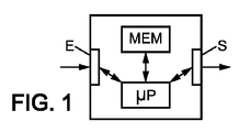
図1を参照すると、本発明を、
−データ入力装置E
−結果抽出装置S
−(地図データと位置データを含む)メモリMEM
−算術論理計算ユニットμP
を有するかまたはエミュレートする装置の任意の要素で実施することができる。可能な例示的な実施形態は、フォン・ノイマン・アーキテクチャ(マイクロコントローラ、マイクロプロセッサ、PC等)および(ASIC、FPGA、CPLD等)プログラム可能論理アーキテクチャから導出される。
Referring to FIG. 1, the present invention is
-Data input device E
-Result extraction device S
-Memory MEM (including map data and position data)
-Arithmetic logic unit μP
Can be implemented on any element of the device having or emulating. Possible exemplary embodiments are derived from von Neumann architecture (microcontroller, microprocessor, PC, etc.) and programmable logic architecture (ASIC, FPGA, CPLD, etc.).
このように、装置Eへの入力は、探索すべきモバイルの周囲の近傍環境を表現するデータである。これらのデータは、様々なセンサ(例えば、LIDAR)から生ずることができ、地図に分類すべきオブジェクトの存在を示す空間またはフリー・ゾーンの点のデカルト座標に変換可能である。これらの座標は、発見すべきモバイルに束縛された参照フレームで表現される。 As described above, the input to the device E is data representing the nearby environment around the mobile to be searched. These data can originate from various sensors (eg, LIDAR) and can be converted to Cartesian coordinates of points in the space or free zone that indicate the presence of objects to be classified into the map. These coordinates are expressed in a reference frame bound to the mobile to be discovered.
eにより、マップすべきエンティティの座標を(大量の点の形で)表す、システムの入力を示す。一般に、 e indicates the input of the system representing the coordinates of the entity to be mapped (in the form of a large number of points). In general,

である。ここで、eiはシステムのi番目の入力であり、 It is. Where e i is the i th input of the system,
![]()
![]()
は、点の座標から成るベクトルであり、 Is a vector of point coordinates,
![]()
![]()
は、各点のステータス(占有/空き)に関するベクトルである。
平面問題(2D地図の決定)のケースでは、
Is a vector regarding the status (occupancy / vacancy) of each point.
In the case of a plane problem (determination of a 2D map)
である。ここで、X0、Y0はモバイルの参照フレームで表現される(例えば、LIDARから生ずる)点の座標である。実際、2D地図製作に関して、本発明の趣旨に入る技術と互換性のある取得システムは、例えば(特に、LIDARタイプの)LASERスキャンに基づくようなテレメータである。 It is. Here, X 0 and Y 0 are the coordinates of a point represented by a mobile reference frame (for example, generated from LIDAR). In fact, for 2D cartography, an acquisition system that is compatible with the technology that falls within the spirit of the present invention is a telemeter, for example, based on a LASER scan (particularly of the LIDAR type).
システムの出力[PV]は2つの形で与えられる。
−P:絶対参照フレームにおけるモバイルの位置データ
−V:確率論的占有グリッド
The system output [PV] is given in two forms.
-P: Mobile location data in absolute reference frame -V: Probabilistic occupancy grid
の形で探索されたゾーンの地図データ。当該グリッドの各セルは当該グリッド内の障害物の存在確率を表す。 Map data of the zone searched in the form of. Each cell of the grid represents the existence probability of an obstacle in the grid.
モバイルの位置は、当該モバイルの位置と方位を含む空間内の座標の形で表される。一般に、 The mobile position is represented in the form of coordinates in space including the mobile position and orientation. In general,
である。ここで、Pはシステムの入力であり、 It is. Where P is the system input,
は空間内の位置であり、 Is the position in space,
は空間内の方位である。 Is the orientation in space.
(2D地図を構築するための)平面問題の特別なケースでは、 In the special case of plane problems (for building 2D maps)
である。 It is.
処理すべきデータが入力装置に存在するときには、第1の一連の測定の後、以下で説明する処理により、モバイルの位置と環境の地図を更新することができる。 When data to be processed is present in the input device, the map of the mobile location and environment can be updated by the process described below after the first series of measurements.
しかし、図2を参照すると、以下のように、第1の反復を別々に処理して当該処理を開始しなければならない。 However, referring to FIG. 2, the first iteration must be processed separately and the process started as follows.
開始コマンドS0の後、第1の一連の測定を実施する過程で、ステップ集合S1の最初の反復は、当該処理の初期化と第1の情報の環境地図への書込みを目的とする。当該情報は、当該処理において以降参照される。 In the process of performing the first series of measurements after the start command S0, the first iteration of the step set S1 aims at initializing the process and writing the first information to the environment map. This information is referred to hereinafter in the processing.
当該ステップ集合S1は3つのステップから成る。即ち、
−地図を更新するステップS11
−地図をセグメント化するステップS12
−最近傍への距離を計算するステップS13
The step set S1 includes three steps. That is,
-Step S11 for updating the map
Step S12 for segmenting the map
Step S13 for calculating the distance to the nearest neighbor
ステップS11では、モバイルの初期位置は未知であると仮定する。例えば、当該初期位置がゼロであると仮定することができる。モバイルの位置に対応する変数は、当該初期位置を、例えば、
−2D地図では、平面内で位置変数X、Y、θにより、
−または、3D地図では、空間内で位置変数X、Y、Z、φ、ψおよびθにより、
表す。
In step S11, it is assumed that the initial position of the mobile is unknown. For example, it can be assumed that the initial position is zero. The variable corresponding to the mobile location is the initial location, eg
In the -2D map, the position variables X, Y, and θ in the plane
-Or in a 3D map, with position variables X, Y, Z, φ, ψ and θ in space,
Represent.
モバイルの位置を知り、地図内で分類すべき測定点の位置e0に基づいて、点ごとに関連セル Know the mobile location and based on the measurement point location e 0 to be classified in the map
を計算して、その値を更新する。例えば、LIDARタイプの測定機器のケースでは、2D地図製作に関して、セルの座標が、 And update its value. For example, in the case of a LIDAR type measuring instrument, the cell coordinates for 2D cartography are
により与えられる。ここで、
−Xmobile、Ymobileは当該モバイルに結び付けられた参照フレーム内の点の座標であり、
−変数Distanceは現在の点に対してLIDARで測定した距離であり、
−変数Alphaは現在の点の測定角度に対応し、
−変数STEP MAPは地図のセルの幅に対応し、
−ベクトル[Tx、Ty]は地図の原点に対するモバイルの想定した移動に対応し、
−Rzは地図の原点に対するモバイルの想定した方位であり、
−x、yは更新すべきセルのインデックスに対応する整数である。
Given by. here,
-X mobile , Y mobile are the coordinates of the point in the reference frame associated with the mobile,
The variable distance is the distance measured with LIDAR from the current point,
The variable Alpha corresponds to the measurement angle of the current point,
-The variable STEP MAP corresponds to the width of the map cell,
The vector [Tx, Ty] corresponds to the assumed movement of the mobile relative to the map origin,
-Rz is the mobile's assumed orientation relative to the map origin,
-X and y are integers corresponding to the index of the cell to be updated.
ステップS11の実装に関して、幾つかの更新機構を想定することができる。この更新機構には、二乗、平均、またはベイズ平均機構が含まれうる。 Several update mechanisms can be assumed for the implementation of step S11. This update mechanism may include a square, average, or Bayesian average mechanism.
例えば、以下の式で示すように、反復平均を使用することができる。 For example, iterative averaging can be used as shown in the following equation.
訪問数を束縛することにより、忘却因子を挿入することができる。その結果、以下のように最近の取得に対して高い重要度を与えることができる。 By forcing the number of visits, a forgetting factor can be inserted. As a result, high importance can be given to recent acquisitions as follows.
単純かつ効果的な解決策では、セルが空いているか占有されているかに応じて以前の値に定数を追加するかまたは以前の値から定数を差し引く。 A simple and effective solution is to add a constant to the previous value or subtract the constant from the previous value depending on whether the cell is free or occupied.
以下のステップS12では、確率論的地図をセグメント化して当該地図を第2のバイナリ地図、即ち、 In step S12 below, the probabilistic map is segmented and the map is converted to a second binary map, i.e.
に変換する。当該新たな地図の各セルは2つの状態、即ち、空きまたは占有しか有さない。幾つかのセグメント化技法を想定できるが、値の単純な閾値化で実際に十分である。図3Aは、2D地図製作に関して、モバイルPMの初期位置周りの角度間隔θi(Nを角度間隔の数として、i=1、・・・、N)によるセグメント化の例示的な実施形態を示す。勿論、黒点は障害物点を示す。図3Bに示すように、角度セクタAの全体をスキャンすると、最終的に新たな更新された地図が得られる。 Convert to Each cell of the new map has only two states: empty or occupied. Several segmentation techniques can be envisaged, but simple thresholding of values is actually sufficient. FIG. 3A illustrates an exemplary embodiment of segmentation by angular spacing θ i (where N is the number of angular spacings, i = 1,..., N) around the initial position of the mobile PM for 2D cartography. . Of course, the black dots indicate obstacle points. As shown in FIG. 3B, scanning the entire angular sector A will eventually yield a new updated map.
有利には、空間内のモバイルの絶対位置の指示を参照して、絶対参照フレームで得られた地図データを決定することができる。 Advantageously, the map data obtained in the absolute reference frame can be determined with reference to an indication of the absolute position of the mobile in space.
以下のステップS13は、図3Aまたは3Bに従う第1の一連の測定に従って分類される地図要素の最近傍への距離を計算することに対応する。地図の夫々の空のセルには、以下のように、当該最近傍への限界距離を表す値が関連付けられる。 The following step S13 corresponds to calculating the distance to the nearest neighbor of the map element classified according to the first series of measurements according to FIG. 3A or 3B. Each empty cell of the map is associated with a value representing the limit distance to the nearest neighbor as follows.
ここで、 here,
はインデックス Is an index
のセルに関連付けられたユークリッド距離であり、
−Dppvは最近傍の占有セルとのユークリッド距離であり、
−Dmaxは、2つの連続した取得の間における、点の変位の最大ユークリッド距離である。
The Euclidean distance associated with the cell,
-Dppv is the Euclidean distance from the nearest occupied cell,
-Dmax is the maximum Euclidean distance of point displacement between two successive acquisitions.
当該処理を加速するための有利な操作では、特に距離計算に関して、予め計算したテーブル(LUTタイプの「ルックアップ・テーブル」)を使用する。当該テーブルは、メモリにロードされ、中心点、即ち円錐の頂点から遠ざかる(距離が増大する)円錐を表示する図4に示すように、所与の点に対して、当該点からの1組の予め計算した距離を含む。有利には、この事前準備により、所与の点の近傍間のユークリッド距離の計算(特に、二乗根の計算)を不要とすることができる。 An advantageous operation for accelerating the process uses a pre-calculated table (LUT type “look-up table”), especially for distance calculations. The table is loaded into memory and for a given point, a set of points from that point, as shown in FIG. 4, which displays the center point, ie, a cone away from the vertex of the cone (increasing distance). Includes pre-calculated distance. Advantageously, this advance preparation makes it unnecessary to calculate the Euclidean distance between the neighborhoods of a given point, in particular the calculation of the square root.
距離を計算した後のセグメント化された地図を図5に示す。白のセルは、最大変位Dmaxより長い距離だけ離れた最近傍を有するセルである。黒のセルは、占有されたセルである(それらは最近傍であるので、距離はゼロである)。残りのセルは、距離が0とDmaxの間にあるセルであり、グレーのレベルは最近傍への距離を反映する。 The segmented map after calculating the distance is shown in FIG. White cells are cells having nearest neighbors separated by a distance longer than the maximum displacement Dmax . Black cells are occupied cells (the distance is zero because they are nearest neighbors). The remaining cells are those whose distance is between 0 and D max , and the gray level reflects the distance to the nearest neighbor.
ステップS11乃至S13は、ここでは例示のため逐次的に表示しているが、これらのステップを並列に実行してもよく、1点ずつ処理してもよい。 Steps S11 to S13 are sequentially displayed here for illustration, but these steps may be executed in parallel or may be processed one by one.
このように、以上の例では纏めると、点ごとに当該点に関係するセル In this way, in the above example, cells related to the point for each point
を最初に更新し、対応する第2の地図のセル Is first updated and the corresponding second map cell
を更新する。同一セルの近傍の距離 Update. Distance near the same cell
はその後に計算される。次に、図3Aまたは図3Bの地図の測定点がなくなるまで、次の点に移る。 Is then calculated. Next, it moves to the next point until there are no measurement points on the map of FIG. 3A or 3B.
その後、第2の一連の測定を実施する。以下で、どのように図5に示した推定距離から始めて一度かつ同時に、測定機器の変位と地図の新たなデータを決定するかを説明する。 Thereafter, a second series of measurements is performed. In the following, how to determine the displacement of the measuring device and the new data of the map once and simultaneously starting from the estimated distance shown in FIG. 5 will be described.
以下の反復、より一般には上記処理の以下の反復に関して、モバイルの位置が推定され、その後当該推定に基づいて地図データが更新される。したがって、再度図2を参照すると、現在のステップSnのグループは、
−モバイルの位置を推定するステップSn1、
−地図を更新するステップSn2、
−地図をセグメント化するステップSn3、および
−最近傍の距離を計算するステップSn4、
を含む。
ステップSn1で、占有された最近傍への距離を含む探索空間を表すモデルのもとに地図
For the following iterations, and more generally for the following iterations of the above process, the location of the mobile is estimated, and then the map data is updated based on the estimates. Therefore, referring again to FIG. 2, the current group of steps Sn is
-Step Sn1, estimating the position of the mobile,
-Step Sn2, updating the map,
A step Sn3 for segmenting the map, and a step Sn4 for calculating the nearest neighbor distance,
including.
A map based on a model representing the search space including the distance to the nearest nearest neighbor in step Sn1
が生成される。1組の新たな測定データeiが入力装置Eに存在するとき、この1組の測定データをここでは「シーン」と称する。当該処理では、地図モデルと当該シーンの間の最も対応するマッチを求める。 Is generated. When a set of new measurement data ei exists in the input device E, this set of measurement data is referred to herein as a “scene”. In this process, the most corresponding match between the map model and the scene is obtained.
モバイルの想定位置に対して、eiの点ごとに、関連するセルを計算して、その距離の総和を推定する。モバイルの位置に関して、最良の既知の位置で処理を開始することができる。当該位置は、以前の反復で推定された位置から成る。しかし、1実施形態では、場合によってはこの推定を、他のセンサから(例えば、走行距離計測法によって)生ずる測定値で改良してもよい。 With respect to the assumed position of the mobile, for each ei point, a related cell is calculated and the sum of the distances is estimated. With respect to the mobile location, the process can begin at the best known location. The position consists of the position estimated in the previous iteration. However, in one embodiment, in some cases this estimation may be refined with measurements that originate from other sensors (eg, by mileage measurement).
したがって、推定位置を利用することにより、以前のステップ(例えば、図3B)で構築した地図の参照フレームにおいて、最後の取得から生じた各測定点の位置が計算される。次に、これらの点を取得し、図6Aに示すように、以前の反復で取得した地図に重ね合わせる。その後、図5に従う距離の推定で表現したような地図の豊富な情報を利用することによって、最後の測定から生じた点ごとに、図5で前述したように決定された、その最近傍への距離が計算される。新たな点eiごとに、第1の近傍への距離を合計する。次に、第1の距離への距離の合計を表す変数を取得する。当該合計は、数学的分析で従来から使用されている最小二乗和と同様であってもよい。当該処理により、その極小値が求められる数学的関数を記述することができる。 Therefore, by using the estimated position, the position of each measurement point resulting from the last acquisition is calculated in the reference frame of the map constructed in the previous step (eg, FIG. 3B). These points are then acquired and overlaid on the map acquired in the previous iteration, as shown in FIG. 6A. After that, by utilizing the abundant information of the map as expressed in the distance estimation according to FIG. 5, each point resulting from the last measurement is determined as described above in FIG. The distance is calculated. For each new point ei, the distance to the first neighborhood is summed. Next, a variable representing the total distance to the first distance is acquired. The sum may be similar to the least square sum conventionally used in mathematical analysis. By this processing, a mathematical function for which the minimum value is obtained can be described.
そうすると、前述の距離の合計が最小化すべき基準となる。実際、距離の合計がゼロである場合には、そのシーンは当該モデルに完全に対応する。他方、距離の合計が大きい場合には、モデルとシーンはかけ離れている。シーンとモデルが距離Dmax内にある場合には、この2つの間で変換することによりモバイルの変位が正しく反映される。 Then, the sum of the above-mentioned distances becomes a standard to be minimized. In fact, if the total distance is zero, the scene corresponds completely to the model. On the other hand, when the total distance is large, the model and the scene are far apart. If the scene and the model are within the distance Dmax , the mobile displacement is correctly reflected by converting between the two.
図6Bに、(図5の)モデル 6B shows the model (of FIG. 5).
に重ね合わせたシーンei(点)の例を示す。次に、最小化すべき数学的関数Criterion=f(P)を定義する。2D地図の平面においては、当該関数はCriterion=f(X、Y、θ)の形式で表現される。 Shows an example of the superimposed scene ei (point). Next, a mathematical function Criterion = f (P) to be minimized is defined. In the 2D map plane, the function is expressed in the form of Criterion = f (X, Y, θ).
本発明の原理によれば、fは、図7に示すように極小値を受容する関数であることが示される。当該関数は評価可能であるが、その解析的表現は未知である。 In accordance with the principles of the present invention, f is shown to be a function that accepts a local minimum, as shown in FIG. The function can be evaluated, but its analytical expression is unknown.
SLAMの問題のフレームワークにおいて、かつ、ここで全て満足される特定の条件のもとで、局所的なアプローチを使用できそれが非常に良好な結果を与えることは特に明らかである。モバイルの変位に関する仮定が十分に信頼できるものである場合には、当該極小値が実際に求められている最小値である。処理の開始時に、当該情報が当該処理を開始する可能性が十分であると想定される場合には、各反復の結果は同様に十分に信頼できるものである。 It is particularly clear that a local approach can be used in the framework of the SLAM problem and under certain conditions that are all satisfied here, which gives very good results. If the assumption about mobile displacement is sufficiently reliable, the local minimum is the minimum that is actually sought. If it is assumed at the start of the process that the information is likely to start the process, the result of each iteration is equally reliable.
2次元(2D地図製作)における問題に関してθ平面に投影される関数fのプロットの1例を特に図7に示す。当該関数は局所的には1つの最小値しか受容しないことは容易に分かる。同じ傾向が、3D地図製作のフレームワークでも観測されている。 An example of a plot of the function f projected on the θ plane for a problem in two dimensions (2D cartography) is shown in particular in FIG. It is easy to see that the function accepts only one minimum value locally. The same trend has been observed in the 3D cartography framework.
多数の可能な最小値探索アルゴリズムを提供することができる。例えば、ここで良好な結果を与えるNelderとMeadのアルゴリズムを引用してもよい。 A number of possible minimum search algorithms can be provided. For example, the Nelder and Mead algorithm that gives good results may be cited here.
距離の合計の極小値が見つかると、モバイルの新たな位置Piがその結果として分かる。次に、ステップS11、S12、およびS13に関して夫々前述したように、続くステップSn2、Sn3、およびSn4で、メモリ内の地図データを更新することができる。 Once the minimum of the total distance is found, the new mobile location P i is known as a result. Next, as described above with respect to steps S11, S12, and S13, the map data in the memory can be updated in subsequent steps Sn2, Sn3, and Sn4.
このように、手短に述べると、図3Aに示したような第1の取得の後、ルックアップ・テーブル(LUT)を参照して、図5に示すように当該第1の取得から生じた点の周りの第1の近傍の距離が決定される。次の取得により、図6Aに示すように、図3Bで表した以前に構築した地図上に重ね合わせられる点のような、後続の点を決定することができる。(図6Bに示すように)最近傍の距離を与えるルックアップ・テーブルを参照することによって、後に取得した点と以前に構築した地図の点との間の距離の全体和が推定され、当該距離の合計の最小値が求められる。有利には、通常は唯一の極小値が存在する(図7)ことが成り立ち、その結果、図3Bに示す地図内のモバイルの現在位置が曖昧さなく与えられ、最後の取得において新たな測定点を特定して地図のデータを豊富にすることができる。 Thus, in brief, after the first acquisition as shown in FIG. 3A, with reference to the lookup table (LUT), the points resulting from the first acquisition as shown in FIG. A first neighborhood distance around is determined. Subsequent acquisitions can determine subsequent points, such as points that are superimposed on the previously constructed map represented in FIG. 3B, as shown in FIG. 6A. By referring to a look-up table that gives the nearest distance (as shown in FIG. 6B), the total sum of distances between points acquired later and previously constructed map points is estimated, and the distance The minimum value of the sum of is obtained. Advantageously, it usually holds that there is only one local minimum (Fig. 7), so that the mobile's current position in the map shown in Fig. 3B is given unambiguously, and a new measurement point at the last acquisition Can be specified to enrich the map data.
当該処理は、夫々の新たなデータ取得で繰り返され、ランドマーク抽出、無作為抽出、構築論的モデル(分散等)、または重い処理(画像の点の対応または「マッチング」等)を使用せずに、SLAMの問題を解決することができる。したがって、計算時間の点で注目すべき性能を実現することができる。 The process is repeated with each new data acquisition, without using landmark extraction, random sampling, constructive models (such as variance), or heavy processing (such as image point correspondence or "matching") In addition, the problem of SLAM can be solved. Therefore, it is possible to realize performance that should be noted in terms of calculation time.
再び図2を参照すると、勿論、所望の完全な地図が最後のステップSFで構築されない限り、次の一連の測定Sn+1を実施することができ、一群のステップSnを繰り返すことができる。 Referring again to FIG. 2, of course, as long as the desired complete map is not built in the last step SF, the next series of measurements Sn + 1 can be performed and the group of steps Sn can be repeated.
本発明の利点は特に、
−地図の更新のための予め計算したテーブルの利用と、
−位置推定のための局所探索アルゴリズムの利用と、
を根拠とした、計算速度である。
The advantages of the present invention are in particular
-Use of pre-calculated tables for map updates;
-Use of a local search algorithm for position estimation;
This is the calculation speed based on
第2の利点は、得られる精度である。データの高速な処理により、実際に、リアルタイムに地図を更新することができ、結果として多数のデータを使用することができる。次に統計的現象が現れる。これにより、システムの信頼性が高まる。即ち、異常なデータ項目は正当なデータの中に「飲みこまれ」、殆ど結果に影響を及ぼさない。さらに、その後の反復で当該異常なデータ項目の大部分を補正することができる。 The second advantage is the accuracy obtained. Due to the high-speed processing of data, the map can actually be updated in real time, and as a result, a large amount of data can be used. Next, statistical phenomena appear. This increases the reliability of the system. That is, abnormal data items are “swallowed” into legitimate data and have little effect on the results. Further, most of the abnormal data items can be corrected in subsequent iterations.
第3の利点はその簡潔性である。当該処理は、使用する測定機器またはセンサのモデルと独立である。当該処理は、アプリケーションの関数として再計算する必要があろう数学的モデル、モバイルまたはそのセンサの移動特性には依存しない。さらに、処理アルゴリズムの幾つかのパラメータが、物理的な条件(地図の精度とサイズ、モバイルの最大速度、最大変位等)に直接関係し、したがって容易に調節することができる。 The third advantage is its simplicity. This process is independent of the measurement instrument or sensor model used. The process does not depend on the mathematical model, the mobile or its sensor's movement characteristics that would need to be recalculated as a function of the application. In addition, some parameters of the processing algorithm are directly related to physical conditions (map accuracy and size, mobile maximum speed, maximum displacement, etc.) and can therefore be easily adjusted.
当該処理を用いて、モバイルを環境において絶対的に探索することもできる。かかるアプリケーションは、通常「全地球測位」または「キッドナッピング(kidnapping)」と呼ばれ、モバイルを既知の環境の未知の位置に配置し、モバイルが当該環境で絶対的に自己探索する必要がある。本発明では、モバイルが配置される環境に関する以前の(部分的な)地図データをモバイルが当然に有する場合に、かかるアプリケーションを可能とする。 Using this process, the mobile can be absolutely searched for in the environment. Such applications are commonly referred to as “global positioning” or “kidnapping” and require the mobile to be placed at an unknown location in a known environment and the mobile to absolutely self-search in that environment. . The present invention enables such an application when the mobile naturally has previous (partial) map data regarding the environment in which the mobile is located.
勿論、本発明は2Dおよび3Dにおいて等しく適用される。さらに、当該処理を、地図製作に関する本発明の趣旨において使用できるだけでなく、オブジェクト認識に対しても利用することができる。次に、かかるアプリケーションにおいて、建物の地図をオブジェクトのデータベースの構築で置き換えることができる。次に、スキャンされた取得が、オブジェクトの(部分的な)3D取得で置き換えられる。したがって、本発明の別の可能なアプリケーションは、モバイルの支援を受けた、距離の測定による3Dオブジェクトの認識に関する。前述のグローバル距離関数の(明確な)極小値の観測により、本発明の趣旨に入る処理は良好な結果を与えている。 Of course, the present invention applies equally in 2D and 3D. Furthermore, this process can be used not only for the purpose of the present invention relating to cartography, but also for object recognition. Then, in such an application, the building map can be replaced by building a database of objects. The scanned acquisition is then replaced with a (partial) 3D acquisition of the object. Accordingly, another possible application of the present invention relates to the recognition of 3D objects by distance measurement with mobile assistance. By observing the (clear) local minimum of the global distance function described above, the processing within the meaning of the present invention gives good results.
さらに、各々が少なくとも1つの他の機器と通信するのに適した複数の測定機器に対してその地図データを提供して、様々な測定機器から生ずる地図データを照合するステップを実施できるようにしてもよい。有利には、かかる実施形態により、幾つかのモバイルが完全な地図の形成に参加することによる処理時間を厳密に減らすことができる。 In addition, the map data is provided to a plurality of measuring devices each suitable for communicating with at least one other device so that the step of collating the map data originating from the various measuring devices can be performed. Also good. Advantageously, such an embodiment can strictly reduce the processing time due to several mobiles participating in the formation of a complete map.
本発明はまた、以上で説明した方法を実装するための、地図製作データを生成するための装置を目的とする。図8を参照すると、かかる装置は、1つまたは複数の障害物OBSへの距離を測定するための、少なくとも1つのモバイル機器を備える。当該モバイル機器は、
−距離測定ユニットU−MESと、
−機器の変位手段M−DEPと、
−測定データを、地図データと当該地図内のロボットの現在位置とを計算するためのユニットに送信するための通信手段COMと、
−上述の計算ユニットと、
を備える。
The present invention is also directed to an apparatus for generating cartographic data for implementing the method described above. Referring to FIG. 8, such an apparatus comprises at least one mobile device for measuring a distance to one or more obstacles OBS. The mobile device
A distance measuring unit U-MES;
The device displacement means M-DEP;
A communication means COM for sending the measurement data to the unit for calculating the map data and the current position of the robot in the map;
-The calculation unit described above;
Is provided.
特に、計算ユニットMEM−μPは、
−作業メモリMEMにおいて、測定距離と各角度測定間隔を関連付け、
−次の現在位置の角度間隔ごとに測定した距離の関数として、一度かつ同時に、
−上記地図上の測定機器の最新の現在位置と、
−当該地図の新たなデータと
を決定する
ための、少なくとも1つのプロセッサμPと作業メモリMEMを備える。
In particular, the calculation unit MEM-μP is
-In the working memory MEM, associating the measurement distance with each angle measurement interval;
As a function of distance measured at each angular interval of the next current position, once and simultaneously,
-The latest current position of the measuring instrument on the map;
-It comprises at least one processor μP and a working memory MEM for determining the new data of the map.
この目的のため、グローバル距離関数の極小値が図7を参照して上述したように有利に図示される。図8の例では、モバイル機器が上述の計算ユニットを統合する。しかし、変形においては、当該計算ユニットが(例えば、無線通信手段により測定機器に接続されたユニットPCのように)独立であってもよい。 For this purpose, the local minimum of the global distance function is advantageously illustrated as described above with reference to FIG. In the example of FIG. 8, the mobile device integrates the above-described calculation units. However, in a variant, the said calculation unit may be independent (for example, like a unit PC connected to the measuring device by wireless communication means).
さらに、図8の例では、装置MOB1はさらに、(例えば、無線通信による)地図データの送受信手段EM/RECを備えることができる。装置MOB1は、当該地図データを別の装置MOB2と交換して、以上で説明したように上述のタイプの完全な地図を形成することができる。 Further, in the example of FIG. 8, the device MOB1 may further include map data transmission / reception means EM / REC (for example, by wireless communication). The device MOB1 can exchange the map data with another device MOB2 to form a complete map of the type described above as described above.
E データ入力装置
MEM メモリ
μP 算術論理計算ユニット
S 結果抽出装置
E data input device MEM memory μP arithmetic logic unit S result extraction device
Claims (9)
少なくとも1つのモバイル測定機器が前記モバイル測定機器の環境における前記モバイル測定機器の現在位置と障害物の間のユークリッド距離を測定するように設計され、
a)Aを前記モバイル測定機器の前記環境を少なくとも部分的に定義する所定の角度セクタとして、各々A/Nの連続的な角度間隔により、前記環境における前記モバイル測定機器と障害物の間のユークリッド距離を少なくともN回測定し、作業メモリ内で前記ユークリッド距離を夫々の前記角度間隔と関連付けて、地図データを構築するステップと、
b)前記モバイル測定機器を変位させ、前記モバイル測定機器の新たな現在位置に対してステップa)を繰り返すステップと、
c)ステップb)の前記現在位置の角度間隔およびステップa)の過去の位置の角度間隔ごとに測定した前記ユークリッド距離の関数として、一度かつ同時に、
地図上での、ステップa)の前記モバイル測定機器の初期位置に対するステップb)の前記モバイル測定機器の前記現在位置と、
前記地図の新たなデータと、
を決定するステップと、
を含み、
ステップc)において、
ステップa)で決定した前記地図に対する、前記モバイル測定機器と前記障害物の間のグローバル距離の関数を決定し、
前記関数の極小値を図示して、ステップb)における前記モバイル測定機器の現在位置を決定し、
前記グローバル距離関数は、ステップa)で決定した各障害物点とステップb)で障害物として検出した近傍点との間のユークリッド距離の和により推定され、
所与の点の近傍点と、当該所与の点および当該所与の点の近傍の間の推定ユークリッド距離とを対応付けるルックアップ・テーブルが前もって構築され、
前記グローバル距離関数を計算するために、ステップb)で障害物を検出した後、障害物ごとに、最も近い障害物点とのユークリッド距離をステップc)で決定し、前記ルックアップ・テーブルを参照して、前記障害物と前記最も近い障害物点との間のユークリッド距離を決定し、
次いで、前記障害物点の全部に関する前記ユークリッド距離の前記和を推定する、
方法。 A method for generating cartographic data,
At least one mobile measuring device is designed to measure the Euclidean distance between the current position of the mobile measuring device and an obstacle in the environment of the mobile measuring device;
a) Euclidean between the mobile measurement device and the obstacle in the environment, each with a continuous angular spacing of A / N, where A is a predetermined angular sector that at least partially defines the environment of the mobile measurement device Measuring the distance at least N times and associating the Euclidean distance with each of the angular intervals in a working memory to construct map data;
b) displacing the mobile measuring device and repeating step a) for a new current position of the mobile measuring device;
c) as a function of the angular interval of the current position in step b) and the Euclidean distance measured for each angular interval of the past position in step a) once and simultaneously,
The current position of the mobile measuring device of step b) on the map relative to the initial position of the mobile measuring device of step a);
New data of the map;
A step of determining
Including
In step c)
Determining a function of the global distance between the mobile measuring device and the obstacle for the map determined in step a);
Figure out the local minimum of the function to determine the current position of the mobile measuring device in step b);
The global distance function is estimated by a sum of Euclidean distances between each obstacle point determined in step a) and a neighboring point detected as an obstacle in step b) .
A look-up table is constructed in advance that associates a neighborhood point of a given point with the estimated point and the estimated Euclidean distance between the given point and the neighborhood of the given point;
In order to calculate the global distance function, after detecting obstacles in step b), for each obstacle, the Euclidean distance to the nearest obstacle point is determined in step c), and the lookup table is referred to. And determining a Euclidean distance between the obstacle and the nearest obstacle point;
Then, we estimate the sum of the Euclidean distance in the whole of the obstacle point,
Method.
空間内の前記モバイル測定機器の絶対位置を決定する初期ステップa0)を含む、
請求項1および2の何れか1項に記載の方法。 In step a), the map data is constructed as a function of the display of the current position of the mobile measuring device in step a),
Including an initial step a0) for determining the absolute position of the mobile measuring device in space,
3. A method according to any one of claims 1 and 2.
ステップa)を実装するためのユークリッド距離測定ユニットと、
ステップb)を実装するための距離変位手段と、
地図データと前記地図内のロボットの現在位置を計算するための計算ユニットに、測定データを送信するための手段と、
を備えた、距離を測定するための少なくとも1つのモバイル機器を備え、
前記計算ユニットは、少なくとも1つのプロセッサと作業メモリとを備え、
前記作業メモリは、測定されたユークリッド距離を夫々の角度測定間隔と前記作業メモリにおいて関連付けるためのものであり、
ステップc)を実装するために、次の現在位置の角度間隔ごとに測定した前記ユークリッド距離の関数として、一度かつ同時に、
前記地図上で前記モバイル測定機器の最後の現在位置と、
前記地図の新たなデータと
を、
ステップa)で決定した前記地図に関して、前記モバイル測定機器と前記障害物の間のグローバル距離の関数を決定し、
前記関数の極小値を図示して、ステップb)における前記モバイル測定機器の現在位置を決定する
ことによって決定し、
前記グローバル距離関数は、ステップa)で決定した各障害物点とステップb)で障害物として検出した近傍点との間のユークリッド距離の和により推定され、
所与の点の近傍点と、当該所与の点および当該所与の点の近傍の間の推定ユークリッド距離とを対応付けるルックアップ・テーブルが前もって構築され、
前記グローバル距離関数を計算するために、ステップb)で障害物を検出した後、障害物ごとに、最も近い障害物点とのユークリッド距離をステップc)で決定し、前記ルックアップ・テーブルを参照して、前記障害物と前記最も近い障害物点との間のユークリッド距離を決定し、
次いで、前記障害物点の全部に関する前記ユークリッド距離の前記和を推定する、
装置。 For implementing the method according to any one of claims 1 to 7, an apparatus for generating cartographic data,
A Euclidean distance measurement unit for implementing step a);
Distance displacement means for implementing step b);
Means for transmitting the measurement data to the calculation unit for calculating the map data and the current position of the robot in the map;
Comprising at least one mobile device for measuring distance, comprising:
The computing unit comprises at least one processor and a working memory;
The working memory is for associating a measured Euclidean distance with a respective angular measurement interval in the working memory;
As a function of the Euclidean distance measured at each angular interval of the next current position to implement step c) once and simultaneously,
The last current location of the mobile measuring device on the map;
New data of the map and
For the map determined in step a), determining a function of the global distance between the mobile measuring device and the obstacle;
Determining the local minimum of the function by determining the current position of the mobile measuring device in step b);
The global distance function is estimated by a sum of Euclidean distances between each obstacle point determined in step a) and a neighboring point detected as an obstacle in step b) .
A look-up table is constructed in advance that associates a neighborhood point of a given point with the estimated point and the estimated Euclidean distance between the given point and the neighborhood of the given point;
In order to calculate the global distance function, after detecting obstacles in step b), for each obstacle, the Euclidean distance to the nearest obstacle point is determined in step c), and the lookup table is referred to. And determining a Euclidean distance between the obstacle and the nearest obstacle point;
Then, we estimate the sum of the Euclidean distance in the whole of the obstacle point,
apparatus.
Applications Claiming Priority (3)
| Application Number | Priority Date | Filing Date | Title |
|---|---|---|---|
| FR1155625 | 2011-06-24 | ||
| FR1155625A FR2977023B1 (en) | 2011-06-24 | 2011-06-24 | GENERATION OF CARD DATA |
| PCT/FR2012/051427 WO2012175888A1 (en) | 2011-06-24 | 2012-06-22 | Generation of map data |
Publications (2)
| Publication Number | Publication Date |
|---|---|
| JP2014523572A JP2014523572A (en) | 2014-09-11 |
| JP6456141B2 true JP6456141B2 (en) | 2019-01-23 |
Family
ID=46456919
Family Applications (1)
| Application Number | Title | Priority Date | Filing Date |
|---|---|---|---|
| JP2014516428A Expired - Fee Related JP6456141B2 (en) | 2011-06-24 | 2012-06-22 | Generating map data |
Country Status (5)
| Country | Link |
|---|---|
| US (1) | US10288425B2 (en) |
| EP (1) | EP2724203B1 (en) |
| JP (1) | JP6456141B2 (en) |
| FR (1) | FR2977023B1 (en) |
| WO (1) | WO2012175888A1 (en) |
Families Citing this family (15)
| Publication number | Priority date | Publication date | Assignee | Title |
|---|---|---|---|---|
| ES2675363T3 (en) * | 2014-06-05 | 2018-07-10 | Softbank Robotics Europe | Procedure for constructing a probability map between the absence and the presence of obstacles for an autonomous robot |
| CN104647344B (en) * | 2015-03-18 | 2016-11-30 | 重庆交通大学 | Three-dimensional map structure Work robot |
| JP6528641B2 (en) * | 2015-10-26 | 2019-06-12 | トヨタ自動車株式会社 | Self-position estimation method |
| KR101868374B1 (en) * | 2016-10-20 | 2018-06-18 | 엘지전자 주식회사 | Control method of a moving-robotf |
| CN107688665B (en) * | 2017-09-27 | 2021-07-02 | 深圳大学 | Automatic indoor map construction method and device and storage medium |
| CN107861132A (en) * | 2017-10-27 | 2018-03-30 | 上海斐讯数据通信技术有限公司 | A kind of GPS track optimization method and device |
| KR102275300B1 (en) | 2019-07-05 | 2021-07-08 | 엘지전자 주식회사 | Moving robot and control method thereof |
| KR102224637B1 (en) | 2019-07-05 | 2021-03-08 | 엘지전자 주식회사 | Moving robot and control method thereof |
| KR102361130B1 (en) | 2019-07-11 | 2022-02-09 | 엘지전자 주식회사 | Moving robot and control method thereof |
| KR102297496B1 (en) * | 2019-07-11 | 2021-09-02 | 엘지전자 주식회사 | A ROBOT CLEANER Using artificial intelligence AND CONTROL METHOD THEREOF |
| KR102302575B1 (en) * | 2019-07-16 | 2021-09-14 | 엘지전자 주식회사 | Moving robot and control method thereof |
| CN110515386A (en) * | 2019-09-19 | 2019-11-29 | 小狗电器互联网科技(北京)股份有限公司 | A kind of intelligent robot |
| CN111161424B (en) * | 2019-12-30 | 2023-06-02 | 浙江欣奕华智能科技有限公司 | Determination method and determination device for three-dimensional map |
| CN111060113B (en) * | 2019-12-31 | 2022-04-08 | 歌尔股份有限公司 | Map updating method and device |
| CN117870653B (en) * | 2024-03-13 | 2024-05-14 | 中国科学技术大学 | Method for establishing and updating two-dimensional differential Euclidean symbol distance field map |
Family Cites Families (12)
| Publication number | Priority date | Publication date | Assignee | Title |
|---|---|---|---|---|
| JPH0953939A (en) * | 1995-08-18 | 1997-02-25 | Fujitsu Ltd | Method and system for measuring position of mobile vehicle |
| US20050234679A1 (en) * | 2004-02-13 | 2005-10-20 | Evolution Robotics, Inc. | Sequential selective integration of sensor data |
| JP4533659B2 (en) * | 2004-05-12 | 2010-09-01 | 株式会社日立製作所 | Apparatus and method for generating map image by laser measurement |
| JP4300199B2 (en) * | 2005-06-13 | 2009-07-22 | 株式会社東芝 | Mobile robot, mobile robot position and orientation calculation method, mobile robot autonomous traveling system |
| KR100843085B1 (en) * | 2006-06-20 | 2008-07-02 | 삼성전자주식회사 | Method of building gridmap in mobile robot and method of cell decomposition using it |
| JP5112666B2 (en) * | 2006-09-11 | 2013-01-09 | 株式会社日立製作所 | Mobile device |
| JP2008250906A (en) * | 2007-03-30 | 2008-10-16 | Sogo Keibi Hosho Co Ltd | Mobile robot, and self-location correction method and program |
| JP5032953B2 (en) * | 2007-11-26 | 2012-09-26 | パナソニック株式会社 | Self-position recognition system |
| KR101457148B1 (en) * | 2008-05-21 | 2014-10-31 | 삼성전자 주식회사 | Apparatus for localizing moving robot and method the same |
| JP5298741B2 (en) * | 2008-10-01 | 2013-09-25 | 村田機械株式会社 | Autonomous mobile device |
| US8473141B2 (en) * | 2008-12-11 | 2013-06-25 | Kabushiki Kaisha Yaskawa Denki | Robot system |
| JP5452442B2 (en) * | 2010-10-25 | 2014-03-26 | 株式会社日立製作所 | Robot system and map updating method |
-
2011
- 2011-06-24 FR FR1155625A patent/FR2977023B1/en not_active Expired - Fee Related
-
2012
- 2012-06-22 EP EP12731600.8A patent/EP2724203B1/en not_active Not-in-force
- 2012-06-22 US US14/128,948 patent/US10288425B2/en not_active Expired - Fee Related
- 2012-06-22 JP JP2014516428A patent/JP6456141B2/en not_active Expired - Fee Related
- 2012-06-22 WO PCT/FR2012/051427 patent/WO2012175888A1/en active Application Filing
Also Published As
| Publication number | Publication date |
|---|---|
| FR2977023A1 (en) | 2012-12-28 |
| EP2724203B1 (en) | 2017-09-13 |
| FR2977023B1 (en) | 2014-02-21 |
| EP2724203A1 (en) | 2014-04-30 |
| US10288425B2 (en) | 2019-05-14 |
| US20140142891A1 (en) | 2014-05-22 |
| WO2012175888A1 (en) | 2012-12-27 |
| JP2014523572A (en) | 2014-09-11 |
Similar Documents
| Publication | Publication Date | Title |
|---|---|---|
| JP6456141B2 (en) | Generating map data | |
| US8792726B2 (en) | Geometric feature extracting device, geometric feature extracting method, storage medium, three-dimensional measurement apparatus, and object recognition apparatus | |
| CN109710724B (en) | A kind of method and apparatus of building point cloud map | |
| Bae et al. | A method for automated registration of unorganised point clouds | |
| US8199977B2 (en) | System and method for extraction of features from a 3-D point cloud | |
| CN111486855A (en) | Indoor two-dimensional semantic grid map construction method with object navigation points | |
| JP5181704B2 (en) | Data processing apparatus, posture estimation system, posture estimation method and program | |
| CN112384891B (en) | Method and system for point cloud coloring | |
| CN113139453B (en) | Orthoimage high-rise building base vector extraction method based on deep learning | |
| JP5480667B2 (en) | Position / orientation measuring apparatus, position / orientation measuring method, program | |
| CN110599489A (en) | Target space positioning method | |
| CN111709988B (en) | Method and device for determining characteristic information of object, electronic equipment and storage medium | |
| CN110187337B (en) | LS and NEU-ECEF space-time registration-based high maneuvering target tracking method and system | |
| CN115880364A (en) | Robot pose estimation method based on laser point cloud and visual SLAM | |
| CN114217665A (en) | Camera and laser radar time synchronization method, device and storage medium | |
| CN114494629A (en) | Three-dimensional map construction method, device, equipment and storage medium | |
| CN115526914A (en) | Robot real-time positioning and color map fusion mapping method based on multiple sensors | |
| KR102547333B1 (en) | Depth Image based Real-time ground detection method | |
| CN115239899B (en) | Pose map generation method, high-precision map generation method and device | |
| CN115937449A (en) | High-precision map generation method and device, electronic equipment and storage medium | |
| CN118279515B (en) | Real-time multi-terminal map fusion method and device | |
| CN118505756A (en) | Pose generation method and device, electronic equipment, storage medium, product and vehicle | |
| CN115200601A (en) | Navigation method, navigation device, wheeled robot and storage medium | |
| CN117830559A (en) | Live working scene modeling method and device, storage medium and computer equipment | |
| KR20230057944A (en) | Method and computing device for apparatus for global localization of mobile robots |
Legal Events
| Date | Code | Title | Description |
|---|---|---|---|
| A621 | Written request for application examination |
Free format text: JAPANESE INTERMEDIATE CODE: A621 Effective date: 20150612 |
|
| A977 | Report on retrieval |
Free format text: JAPANESE INTERMEDIATE CODE: A971007 Effective date: 20160420 |
|
| A131 | Notification of reasons for refusal |
Free format text: JAPANESE INTERMEDIATE CODE: A131 Effective date: 20160509 |
|
| A521 | Request for written amendment filed |
Free format text: JAPANESE INTERMEDIATE CODE: A523 Effective date: 20160802 |
|
| A02 | Decision of refusal |
Free format text: JAPANESE INTERMEDIATE CODE: A02 Effective date: 20170123 |
|
| A521 | Request for written amendment filed |
Free format text: JAPANESE INTERMEDIATE CODE: A523 Effective date: 20170523 |
|
| A521 | Request for written amendment filed |
Free format text: JAPANESE INTERMEDIATE CODE: A523 Effective date: 20170525 |
|
| A911 | Transfer to examiner for re-examination before appeal (zenchi) |
Free format text: JAPANESE INTERMEDIATE CODE: A911 Effective date: 20170613 |
|
| A912 | Re-examination (zenchi) completed and case transferred to appeal board |
Free format text: JAPANESE INTERMEDIATE CODE: A912 Effective date: 20170810 |
|
| A521 | Request for written amendment filed |
Free format text: JAPANESE INTERMEDIATE CODE: A523 Effective date: 20181004 |
|
| A61 | First payment of annual fees (during grant procedure) |
Free format text: JAPANESE INTERMEDIATE CODE: A61 Effective date: 20181218 |
|
| R150 | Certificate of patent or registration of utility model |
Ref document number: 6456141 Country of ref document: JP Free format text: JAPANESE INTERMEDIATE CODE: R150 |
|
| LAPS | Cancellation because of no payment of annual fees |