JP6454746B2 - Swivel frame of work machine - Google Patents
Swivel frame of work machine Download PDFInfo
- Publication number
- JP6454746B2 JP6454746B2 JP2017056042A JP2017056042A JP6454746B2 JP 6454746 B2 JP6454746 B2 JP 6454746B2 JP 2017056042 A JP2017056042 A JP 2017056042A JP 2017056042 A JP2017056042 A JP 2017056042A JP 6454746 B2 JP6454746 B2 JP 6454746B2
- Authority
- JP
- Japan
- Prior art keywords
- reinforcing member
- frame
- bearing
- rear end
- swing
- Prior art date
- Legal status (The legal status is an assumption and is not a legal conclusion. Google has not performed a legal analysis and makes no representation as to the accuracy of the status listed.)
- Expired - Fee Related
Links
Images


Classifications
-
- B—PERFORMING OPERATIONS; TRANSPORTING
- B66—HOISTING; LIFTING; HAULING
- B66C—CRANES; LOAD-ENGAGING ELEMENTS OR DEVICES FOR CRANES, CAPSTANS, WINCHES, OR TACKLES
- B66C23/00—Cranes comprising essentially a beam, boom, or triangular structure acting as a cantilever and mounted for translatory of swinging movements in vertical or horizontal planes or a combination of such movements, e.g. jib-cranes, derricks, tower cranes
- B66C23/62—Constructional features or details
- B66C23/84—Slewing gear
-
- B—PERFORMING OPERATIONS; TRANSPORTING
- B62—LAND VEHICLES FOR TRAVELLING OTHERWISE THAN ON RAILS
- B62D—MOTOR VEHICLES; TRAILERS
- B62D21/00—Understructures, i.e. chassis frame on which a vehicle body may be mounted
- B62D21/18—Understructures, i.e. chassis frame on which a vehicle body may be mounted characterised by the vehicle type and not provided for in groups B62D21/02 - B62D21/17
- B62D21/186—Understructures, i.e. chassis frame on which a vehicle body may be mounted characterised by the vehicle type and not provided for in groups B62D21/02 - B62D21/17 for building site vehicles or multi-purpose tractors
-
- B—PERFORMING OPERATIONS; TRANSPORTING
- B66—HOISTING; LIFTING; HAULING
- B66C—CRANES; LOAD-ENGAGING ELEMENTS OR DEVICES FOR CRANES, CAPSTANS, WINCHES, OR TACKLES
- B66C23/00—Cranes comprising essentially a beam, boom, or triangular structure acting as a cantilever and mounted for translatory of swinging movements in vertical or horizontal planes or a combination of such movements, e.g. jib-cranes, derricks, tower cranes
- B66C23/18—Cranes comprising essentially a beam, boom, or triangular structure acting as a cantilever and mounted for translatory of swinging movements in vertical or horizontal planes or a combination of such movements, e.g. jib-cranes, derricks, tower cranes specially adapted for use in particular purposes
- B66C23/36—Cranes comprising essentially a beam, boom, or triangular structure acting as a cantilever and mounted for translatory of swinging movements in vertical or horizontal planes or a combination of such movements, e.g. jib-cranes, derricks, tower cranes specially adapted for use in particular purposes mounted on road or rail vehicles; Manually-movable jib-cranes for use in workshops; Floating cranes
-
- B—PERFORMING OPERATIONS; TRANSPORTING
- B66—HOISTING; LIFTING; HAULING
- B66C—CRANES; LOAD-ENGAGING ELEMENTS OR DEVICES FOR CRANES, CAPSTANS, WINCHES, OR TACKLES
- B66C23/00—Cranes comprising essentially a beam, boom, or triangular structure acting as a cantilever and mounted for translatory of swinging movements in vertical or horizontal planes or a combination of such movements, e.g. jib-cranes, derricks, tower cranes
- B66C23/62—Constructional features or details
- B66C23/72—Counterweights or supports for balancing lifting couples
- B66C23/78—Supports, e.g. outriggers, for mobile cranes
-
- E—FIXED CONSTRUCTIONS
- E02—HYDRAULIC ENGINEERING; FOUNDATIONS; SOIL SHIFTING
- E02F—DREDGING; SOIL-SHIFTING
- E02F9/00—Component parts of dredgers or soil-shifting machines, not restricted to one of the kinds covered by groups E02F3/00 - E02F7/00
- E02F9/08—Superstructures; Supports for superstructures
- E02F9/10—Supports for movable superstructures mounted on travelling or walking gears or on other superstructures
- E02F9/12—Slewing or traversing gears
Landscapes
- Engineering & Computer Science (AREA)
- Mechanical Engineering (AREA)
- Structural Engineering (AREA)
- Architecture (AREA)
- Chemical & Material Sciences (AREA)
- Combustion & Propulsion (AREA)
- Transportation (AREA)
- Mining & Mineral Resources (AREA)
- Civil Engineering (AREA)
- General Engineering & Computer Science (AREA)
- Jib Cranes (AREA)
Description
本発明は、旋回ベアリングを介して下部走行体の上部に上部旋回体が旋回可能に設けられた作業機械において、上部旋回体を構成する旋回フレームに関する。 The present invention relates to a swing frame constituting an upper swing body in a work machine in which an upper swing body is pivotably provided on an upper portion of a lower traveling body via a swing bearing.
クレーン等の作業機械においては、例えば特許文献1に開示されているように、旋回ベアリングを介して下部走行体の上部に上部旋回体が旋回可能に設けられている。上部旋回体は、旋回ベアリングに旋回可能に取り付けられた旋回フレームと、吊荷の吊り上げ等を行うブームと、マストとを備えている。作業機械は、例えば、マストの先端部に設けられた上部スプレッダと、旋回フレームに設けられた下部スプレッダとの間に掛け回された起伏ロープによりマストを起伏させることで、ブームを起伏させている。
In a working machine such as a crane, for example, as disclosed in
ところで、旋回フレームには、ブームの基端部が取り付けられるブームフット部が前面に、マストの基端部が取り付けられるマストフット部が上面の前部に、上述の下部スプレッダが上面の後部に、それぞれ設けられている。ブームフット部、マストフット部、および、下部スプレッダには、ブームの自重や吊荷による吊荷重が作用する。 By the way, in the revolving frame, the boom foot part to which the base end part of the boom is attached is on the front surface, the mast foot part to which the base end part of the mast is attached is on the front part on the upper surface, and the above-mentioned lower spreader is on the rear part on the upper surface. Each is provided. The boom foot part, the mast foot part, and the lower spreader are subject to the boom's own weight or a suspension load caused by a suspended load.
作業機械が様々な姿勢をとることや、吊荷作業によって発生する荷重は、旋回フレームに作用して、旋回フレームに変形を生じさせる。この変形は、ブームの先端部やブームの先に取り付けられたジブの先端部のたわみに影響する。その結果、作業機械の吊能力が制限されるという問題がある。 When the work machine takes various postures and the load generated by the hanging work works on the swing frame, the swing frame is deformed. This deformation affects the deflection of the tip of the boom and the tip of the jib attached to the tip of the boom. As a result, there is a problem that the suspension capacity of the work machine is limited.
そこで、旋回フレーム全体の板厚を厚くすることで、旋回フレームの剛性を高めることが考えられる。しかし、重量面において規制が厳しいクレーン等の作業機械において、車両の重量が大幅に増加してしまう。 Therefore, it is conceivable to increase the rigidity of the turning frame by increasing the thickness of the entire turning frame. However, in a working machine such as a crane that is strict in terms of weight, the weight of the vehicle is significantly increased.
本発明の目的は、重量の増加を抑えながら、作業機械の吊能力を向上させることが可能な作業機械の旋回フレームを提供することである。 The objective of this invention is providing the turning frame of the working machine which can improve the suspension capacity of a working machine, suppressing the increase in a weight.
本発明は、旋回ベアリングを介して下部走行体の上部に上部旋回体が旋回可能に設けられた作業機械において、マストおよびブームとともに前記上部旋回体を構成する旋回フレームであって、前記旋回ベアリングの上面に取り付けられた底板と、前記底板の上にそれぞれ立てて設けられ、前記作業機械の左右方向に対向して配置された一対の側板と、前記一対の側板の後端同士を連結する後端部材と、前記側板の前面に設けられ、前記ブームの基端部が取り付けられるブームフット部と、前記側板の上面の前部に設けられ、前記マストの基端部が取り付けられるマストフット部と、前記後端部材に設けられ、連結部材で前記マストに連結されるマスト連結部と、前記旋回フレームを側方から見たときに、前記ブームフット部から前記旋回ベアリングの前部に向かって延びるように配設されるとともに、前記旋回ベアリングの前部につながる下端部を備える第1の補強部材と、前記旋回フレームを側方から見たときに、前記ブームフット部から前記マストフット部に向かって延びるように配設される第2の補強部材と、前記旋回フレームを側方から見たときに、前記マストフット部から前記旋回ベアリングの後部に向かって延びるように配設されるとともに、前記旋回ベアリングの後部につながる下端部を備える第3の補強部材と、前記旋回フレームを側方から見たときに、前記側板の上部に位置するとともに前記旋回ベアリングの後部の上方に位置する中間領域から前記旋回ベアリングの前部に向かって延びるように配設されるとともに、前記旋回ベアリングの前部につながる下端部を備える第4の補強部材と、前記旋回フレームを側方から見たときに、前記中間領域から前記旋回ベアリングの後部に向かって延びるように配設されるとともに、前記旋回ベアリングの後部につながる下端部を備える第5の補強部材と、を有することを特徴とする。 The present invention provides a swing frame that constitutes the upper swing body together with a mast and a boom in a work machine in which an upper swing body is pivotably provided on an upper portion of a lower traveling body via a swing bearing, A bottom plate attached to the upper surface, a pair of side plates provided on the bottom plate so as to stand on the left and right sides of the work machine, and a rear end connecting the rear ends of the pair of side plates A member, a boom foot portion provided on a front surface of the side plate, to which a base end portion of the boom is attached, a mast foot portion provided on a front portion of the upper surface of the side plate, to which the base end portion of the mast is attached A mast connecting portion provided on the rear end member and connected to the mast by a connecting member, and when the swivel frame is viewed from the side, the boom foot portion and the swivel bear A first reinforcing member that is disposed so as to extend toward the front portion of the swinging bearing and that has a lower end connected to the front portion of the swing bearing, and the boom foot when the swing frame is viewed from the side. A second reinforcing member disposed so as to extend from the portion toward the mast foot portion, and when viewed from the side, the swing frame extends from the mast foot portion toward the rear portion of the swing bearing. And a third reinforcing member having a lower end connected to the rear portion of the slewing bearing, and a rear portion of the slewing bearing that is located on an upper portion of the side plate when the slewing frame is viewed from the side. A lower end connected to the front portion of the slewing bearing and extending from the intermediate region located above the slewing bearing to the front portion of the slewing bearing And a lower end connected to the rear portion of the slewing bearing, when the slewing frame is viewed from the side, and extends from the intermediate region toward the rear portion of the slewing bearing. And a fifth reinforcing member provided with a portion.
本発明によると、旋回フレームを側方から見たときに、ブームフット部から旋回ベアリングの前部に向かって延びるように第1の補強部材を設け、ブームフット部からマストフット部に向かって延びるように第2の補強部材を設け、マストフット部から旋回ベアリングの後部に向かって延びるように第3の補強部材を設ける。また、側板の上部に位置するとともに旋回ベアリングの後部の上方に位置する中間領域から旋回ベアリングの前部に向かって延びるように第4の補強部材を設け、中間領域から旋回ベアリングの後部に向かって延びるように第5の補強部材を設ける。第1の補強部材は、旋回ベアリングの前部につながる下端部を備え、第3の補強部材は、旋回ベアリングの後部につながる下端部を備える。また、第4の補強部材は、旋回ベアリングの前部につながる下端部を備え、第5の補強部材は、旋回ベアリングの後部につながる下端部を備える。 According to the present invention, when the swing frame is viewed from the side, the first reinforcing member is provided so as to extend from the boom foot portion toward the front portion of the swing bearing, and extends from the boom foot portion toward the mast foot portion. Thus, the second reinforcing member is provided, and the third reinforcing member is provided so as to extend from the mast foot portion toward the rear portion of the swivel bearing. Further, a fourth reinforcing member is provided so as to extend from an intermediate region located above the side plate and above the rear portion of the slewing bearing toward the front portion of the slewing bearing, and from the intermediate region toward the rear portion of the slewing bearing. A fifth reinforcing member is provided so as to extend. The first reinforcing member includes a lower end portion connected to the front portion of the slewing bearing, and the third reinforcing member includes a lower end portion connected to the rear portion of the slewing bearing. The fourth reinforcing member includes a lower end portion connected to the front portion of the slewing bearing, and the fifth reinforcing member includes a lower end portion connected to the rear portion of the slewing bearing.
ブームの自重や吊荷により、ブームフット部と旋回ベアリングの上面部の前部との間には圧縮荷重が作用するが、第1の補強部材によりこれらの間の部分の剛性が向上するので、これらの間の部分における変形が抑制される。また、このときに、ブームフット部とマストフット部との間には圧縮荷重が作用するが、第2の補強部材によりこれらの間の部分の剛性が向上するので、これらの間の部分における変形が抑制される。また、このときに、マストフット部と旋回ベアリングの上面部の後部との間には引張荷重が作用するが、第3の補強部材によりこれらの間の部分の剛性が向上するので、これらの間の部分における変形が抑制される。また、このときに、中間領域と旋回ベアリングの上面部の前部との間には圧縮荷重が作用するが、第4の補強部材によりこれらの間の部分の剛性が向上するので、これらの間の部分における変形が抑制される。また、このときに、中間領域と旋回ベアリングの上面部の後部との間には引張荷重が作用するが、第5の補強部材によりこれらの間の部分の剛性が向上するので、これらの間の部分における変形が抑制される。 A compression load acts between the boom foot part and the front part of the upper surface part of the swivel bearing due to the boom's own weight and suspended load, but the rigidity of the part between these is improved by the first reinforcing member. The deformation in the portion between these is suppressed. At this time, a compressive load acts between the boom foot portion and the mast foot portion, but the rigidity of the portion between them is improved by the second reinforcing member. Is suppressed. At this time, a tensile load acts between the mast foot portion and the rear portion of the upper surface portion of the slewing bearing. However, the third reinforcing member improves the rigidity of the portion between them. The deformation in the portion is suppressed. Further, at this time, a compressive load acts between the intermediate region and the front portion of the upper surface portion of the slewing bearing, but the rigidity of the portion between them is improved by the fourth reinforcing member. The deformation in the portion is suppressed. At this time, a tensile load acts between the intermediate region and the rear portion of the upper surface portion of the slewing bearing, but the fifth reinforcing member improves the rigidity of the portion between them. Deformation in the portion is suppressed.
このように、旋回フレームの変形を抑制することができるので、作業機械の吊能力を向上させることができる。このとき、5つの補強部材で荷重が作用する箇所の剛性を効率的に向上させているので、補強部材の追加による重量増加を最小限に抑えることができる。よって、重量の増加を抑えながら、作業機械の吊能力を向上させることができる。 Thus, since the deformation | transformation of a turning frame can be suppressed, the suspension capability of a working machine can be improved. At this time, since the rigidity of the portion where the load is applied is efficiently improved by the five reinforcing members, an increase in weight due to the addition of the reinforcing members can be minimized. Therefore, the suspension capacity of the work machine can be improved while suppressing an increase in weight.
以下、本発明の好適な実施の形態について、図面を参照しつつ説明する。 Hereinafter, preferred embodiments of the present invention will be described with reference to the drawings.
(クレーンの構成)
本発明の実施形態による作業機械の旋回フレーム(旋回フレーム)1は、作業機械であるクレーン20に設けられている。クレーン20は、側面図である図1に示すように、後述するブーム32により、吊荷Lを吊り上げる作業(荷役作業)等を行う。
(Configuration of crane)
A swing frame (swivel frame) 1 of a work machine according to an embodiment of the present invention is provided on a
クレーン20は、下部走行体21と、旋回ベアリング22と、上部旋回体23と、を備える。下部走行体21は、クレーン20を走行させる部分である。下部走行体21は、例えばクローラ式であり、ホイール式でもよい。上部旋回体23は、旋回ベアリング22を介して下部走行体21の上部に旋回可能に設けられる。
The
上部旋回体23は、旋回フレーム1と、ブーム32と、マスト33と、を備える。以下、ブーム32側を前側、ブーム32とは反対側を後ろ側とする。
The
旋回フレーム1は、旋回ベアリング22により旋回可能に支持されている。旋回フレーム1は、旋回ベアリング22の上面に取り付けられた、環状で回転しない座面板(図示せず)の上面に複数のボルトで固定されている。旋回フレーム1の左右には、図示しない左フレームや右フレームなどが設けられる。例えば、右フレーム上には、キャブ(運転室)などが設けられる。また、旋回フレーム1の後ろ側には、図示しないカウンタウエイトが分解可能に設けられる。カウンタウエイトは、クレーン20の吊荷Lとバランスをとるためのおもりである。なお、旋回フレーム1は、例えば旋回ベアリング22の後部を境に前後に分割可能な構成であってもよい。
The turning
ブーム32は、例えばラチスであり、吊荷Lの吊り上げ等を行うための起伏部材である。ブーム32は、旋回フレーム1の前端部において、旋回フレーム1に起伏可能に取り付けられている。
The
マスト33は、ブーム32の後ろ側に設けられている。マスト33の先端部と、ブーム32の先端部とは、ガイライン34を介して連結されている。また、マスト33の先端部に設けられた上部スプレッダ39と、旋回フレーム1の後部に設けられた下部スプレッダ(マスト連結部)7とは、ブーム起伏ロープ(連結部材)35を介して連結されている。旋回フレーム1に設けられたウインチ(図示せず)で、ブーム起伏ロープ35を巻取り及び巻出しすることで、マスト33が起伏する結果、ブーム32が起伏する。
The
旋回フレーム1の前面には、ブーム32の基端部が取り付けられるブームフット部5が設けられている。また、旋回フレーム1の上面の前部には、マスト33の基端部が取り付けられるマストフット部6が設けられている。また、旋回フレーム1の上面の後部には、上述した下部スプレッダ7が設けられている。
A
(旋回フレームの構成)
旋回フレーム1を前方から見た正面図である図2に示すように、旋回フレーム1は、旋回ベアリング22の上面に水平に取り付けられた底板2を有している。底板2は、旋回ベアリング22の上面に取り付けられた座面板(図示せず)の上面に取り付けられている。
(Structure of swivel frame)
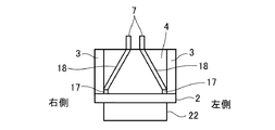
As shown in FIG. 2, which is a front view of the
また、旋回フレーム1は、クレーン20の左右方向に所定の間隔をあけて、底板2の上にそれぞれ立てて設けられた一対の側板3を有している。一対の側板3は、クレーン20の左右方向に対向して配置されている。側板3の下端は、底板2上に溶接されている。また、旋回フレーム1は、クレーン20の前後方向の前側において底板2の上に立てて設けられ、前後方向に面するように配置された前板と、クレーン20の前後方向の後ろ側において底板2の上に設けられ、一対の側板3の後端同士を連結する後端部材4とを有している。後端部材4は、前後方向に間隔をあけて配置された一対の板部材を有している。図2においては、前板の図示を省略している。
The revolving
側板3の前面には、ブームフット部5が設けられ、側板3の上面には、マストフット部6が設けられている。また、後端部材4の上面には、下部スプレッダ7が設けられている。
A
旋回フレーム1を左側から見た断面図である図3に示すように、ブームフット部5、マストフット部6、および、下部スプレッダ7には、ブーム32の自重や吊荷Lによる吊荷重が作用する。これらの荷重は、ブームフット部5に下向きかつ後ろ向きに作用し、マストフット部6に下向きかつ前向きに作用し、下部スプレッダ7に上向きに作用する。これらの荷重は、旋回フレーム1から旋回ベアリング22に伝達される。
As shown in FIG. 3, which is a cross-sectional view of the
クレーン20が様々な姿勢をとることや、吊荷作業によって発生する荷重は、旋回フレーム1に作用して、旋回フレーム1に変形を生じさせる。この変形は、ブーム32の先端部やブーム32の先に取り付けられたジブの先端部のたわみに影響する。その結果、クレーン20の吊能力が制限される。
The load that is generated by the
そこで、本実施形態の旋回フレーム1は、図3に示すように、第1の補強部材11と、第2の補強部材12と、第3の補強部材13と、第4の補強部材14と、第5の補強部材15と、を有している。本実施形態において、これら補強部材11〜15は、金属製であり、円筒や角筒等の中空の管状であるが、板状や円柱状、角柱状であってもよい。また、これら補強部材11〜15は、始めから旋回フレーム1に備えられて、他の部材と一体的に設けられていてもよいし、後付けで旋回フレーム1に取り付けられてもよい。
Therefore, as shown in FIG. 3, the revolving
第1の補強部材11は、図3に示すように、旋回フレーム1を側方から見たときに、ブームフット部5から旋回ベアリング22の上面部の前部(旋回ベアリング22の前部)に向かって直線状に延びるように設けられている。旋回フレーム1の上面図である図4Aに示すように、第1の補強部材11は、ブームフット部5と旋回ベアリング22の上面部の前部とをつなぐように配置されている。第1の補強部材11の上端部(基端部)は、側板3の内面に固定され、第1の補強部材11の下端部(旋回ベアリング22側の先端部)は、底板2に固定されている。この結果、第1の補強部材11の下端部は、底板2および座面板22aを介して、旋回ベアリング22の上面部の前部につながっている。また、第1の補強部材11の下端部は、左右一対の側板3から左右方向の内側にそれぞれ間隔をおいた位置で底板2に固定されている。なお、図4Aにおいては、底板2、前板および後端部材4の図示を省略している。また、補強部材の固定手段は、ボルト、溶接など公知の任意の接合手段を用いることができる。
As shown in FIG. 3, the first reinforcing
第2の補強部材12は、図3に示すように、旋回フレーム1を側方から見たときに、ブームフット部5からマストフット部6に向かって直線状に延びるように設けられている。図4Aに示すように、第2の補強部材12は、ブームフット部5とマストフット部6とをつなぐように配置されている。第2の補強部材12の側面は、上端から下端にわたって側板3の内面に固定されている。
As shown in FIG. 3, the second reinforcing
第3の補強部材13は、図3に示すように、旋回フレーム1を側方から見たときに、マストフット部6から旋回ベアリング22の上面部の後部(旋回ベアリング22の後部)に向かって直線状に延びるように設けられている。図4Aに示すように、第3の補強部材13は、マストフット部6と旋回ベアリング22の上面部の後部とをつなぐように配置されている。第3の補強部材13の上端部(基端部)は、側板3の内面に固定され、第3の補強部材13の下端部(旋回ベアリング22側の先端部)は、底板2に固定されている。この結果、第3の補強部材13の下端部は、底板2および座面板22aを介して、旋回ベアリング22の上面部の後部につながっている。また、第3の補強部材13の下端部は、左右一対の側板3から左右方向の内側にそれぞれ間隔をおいた位置で底板2に固定されている。
As shown in FIG. 3, the third reinforcing
第4の補強部材14は、図3に示すように、旋回フレーム1を側方から見たときに、側板3の上部に位置するとともに旋回ベアリング22の後部の上方に位置する中間領域Mから旋回ベアリング22の上面部の前部(旋回ベアリング22の前部)に向かって直線状に延びるように設けられている。旋回フレーム1の上面図である図4Bに示すように、第4の補強部材14は、中間領域Mと旋回ベアリング22の上面部の前部とをつなぐように配置されている。第4の補強部材14の側面は、上端から下端にわたって側板3の内面に固定されている。また、第4の補強部材14の下端部(旋回ベアリング22側の先端部)は、底板2に固定されている。この結果、第4の補強部材14の下端部は、底板2および座面板22aを介して、旋回ベアリング22の上面部の前部につながっている。なお、中間領域Mは、側板3の上端部に位置していることが望ましい。なお、図4Bにおいては、底板2、前板および後端部材4の図示を省略している。
As shown in FIG. 3, the fourth reinforcing
第5の補強部材15は、図3に示すように、旋回フレーム1を側方から見たときに、中間領域Mから旋回ベアリング22の上面部の後部(旋回ベアリング22の後部)に向かって直線状に延びるように設けられている。図4Bに示すように、第5の補強部材15は、中間領域Mと旋回ベアリング22の上面部の後部とをつなぐように配置されている。第5の補強部材15の側面は、上端から下端にわたって側板3の内面に固定されている。第5の補強部材15の下端部(旋回ベアリング22側の先端部)は、底板2に固定されている。この結果、第5の補強部材15の下端部は、底板2および座面板22aを介して、旋回ベアリング22の上面部の後部につながっている。
As shown in FIG. 3, the fifth reinforcing
ブーム32の自重や吊荷Lにより、ブームフット部5と旋回ベアリング22の上面部の前部との間には圧縮荷重が作用するが、第1の補強部材11によりこれらの間の部分の剛性が向上するので、これらの間の部分における変形が抑制される。また、このときに、ブームフット部5とマストフット部6との間には圧縮荷重が作用するが、第2の補強部材12によりこれらの間の部分の剛性が向上するので、これらの間の部分における変形が抑制される。また、このときに、マストフット部6と旋回ベアリング22の上面部の後部との間には引張荷重が作用するが、第3の補強部材13によりこれらの間の部分の剛性が向上するので、これらの間の部分における変形が抑制される。
A compressive load acts between the
また、このときに、中間領域Mと旋回ベアリング22の上面部の前部との間には圧縮荷重が作用するが、第4の補強部材14によりこれらの間の部分の剛性が向上するので、これらの間の部分における変形が抑制される。また、このときに、中間領域Mと旋回ベアリング22の上面部の後部との間には引張荷重が作用するが、第5の補強部材15によりこれらの間の部分の剛性が向上するので、これらの間の部分における変形が抑制される。
At this time, a compressive load acts between the intermediate region M and the front portion of the upper surface portion of the slewing
このように、旋回フレーム1の変形を抑制することができるので、クレーン20の吊能力を向上させることができる。このとき、5つの補強部材11〜15で荷重が作用する箇所の剛性を効率的に向上させているので、補強部材11〜15の追加による重量増加を最小限に抑えることができる。よって、重量の増加を抑えながら、クレーン20の吊能力を向上させることができる。
Thus, since the deformation | transformation of the revolving
また、旋回フレーム1は、図3に示すように、第6の補強部材16と、第7の補強部材17と、第8の補強部材18と、を有している。本実施形態において、これら補強部材16〜18は、金属製であり、円筒や角筒等の中空の管状であるが、板状や円柱状、角柱状であってもよい。また、これら補強部材16〜18は、始めから旋回フレーム1に備えられて、他の部材と一体的に設けられていてもよいし、後付けで旋回フレーム1に取り付けられてもよい。
Further, as shown in FIG. 3, the revolving
第6の補強部材16は、図3に示すように、旋回フレーム1を側方から見たときに、中間領域Mから後端部材4の上部にかけて直線状に設けられている。図4Bに示すように、第6の補強部材16は、中間領域Mと後端部材4の上部とをつなぐように配置されている。第6の補強部材16の側面は、前端から後端にわたって側板3の内面に固定されている。
As shown in FIG. 3, the sixth reinforcing
第7の補強部材17は、図3に示すように、旋回フレーム1を側方から見たときに、第6の補強部材16よりも下方の位置であって旋回ベアリング22の後部の上方の位置から後端部材4の下部にかけて直線状に設けられている。図4Bにおいて、第7の補強部材17は、第6の補強部材16よりも紙面の奥側に位置しており、第6の補強部材16よりも下方の位置であって旋回ベアリング22の後部の上方の位置と後端部材4の下部とをつなぐように配置されている。第7の補強部材17の側面は、前端から後端にわたって側板3の内面に固定されている。また、第7の補強部材17の前端部は、底板2に固定されている。
As shown in FIG. 3, the seventh reinforcing
第8の補強部材18は、図3に示すように、旋回フレーム1を側方から見たときに、後端部材4の上部から後端部材4の下部にかけて直線状に設けられている。図4Bにおいて、第8の補強部材18は、第6の補強部材16よりも紙面の奥側において、紙面に直交する方向に延びており、後端部材4の上部と後端部材4の下部とをつなぐように配置されている。第8の補強部材18の側面は、上端から下端にわたって側板3の内面に固定されているとともに、後端部材4の前面に固定されている。
As shown in FIG. 3, the eighth reinforcing
図3に示すように、吊荷Lにより、下部スプレッダ7には上向きの力が作用する。これにより、中間領域Mと後端部材4の上部との間には圧縮荷重が作用するが、第6の補強部材16によりこれらの間の部分の剛性が向上するので、これらの間の部分における変形が抑制される。また、このときに、旋回ベアリング22の上面部の後部と後端部材4の下部との間には引張荷重が作用するが、第7の補強部材17によりこれらの間の部分の剛性が向上するので、これらの間の部分における変形が抑制される。また、このときに、後端部材4の上部と後端部材4の下部との間には引張荷重が作用するが、第8の補強部材18によりこれらの間の部分の剛性が向上するので、これらの間の部分における変形が抑制される。
As shown in FIG. 3, an upward force is applied to the
また、吊荷Lがないときに、カウンタウエイトにより、旋回フレーム1の後部には下向きの力が作用する。これにより、中間領域Mと後端部材4の上部との間には引張荷重が作用するが、第6の補強部材16によりこれらの間の部分の剛性が向上するので、これらの間の部分における変形が抑制される。また、このときに、旋回ベアリング22の上面部の後部と後端部材4の下部との間に圧縮荷重が作用するが、第7の補強部材17によりこれらの間の部分の剛性が向上するので、これらの間の部分における変形が抑制される。また、このときに、後端部材4の上部と後端部材4の下部との間に引張荷重が作用するが、第8の補強部材18によりこれらの間の部分の剛性が向上するので、これらの間の部分における変形が抑制される。
Further, when there is no suspended load L, a downward force acts on the rear portion of the
このように、旋回フレーム1の変形をさらに抑制することができるので、クレーン20の吊能力をさらに向上させることができる。このとき、3つの補強部材16〜18で荷重が作用する箇所の剛性を効率的に向上させているので、補強部材16〜18の追加による重量増加を最小限に抑えることができる。
Thus, since the deformation | transformation of the revolving
また、図3に示すように、第3の補強部材13と第4の補強部材14とが交差する部分において、両者が接合されている。両者を接合することで、接合箇所における旋回フレーム1の剛性をさらに向上させることができる。これにより、旋回フレーム1の変形をさらに抑制することができるので、クレーン20の吊能力をさらに向上させることができる。
Moreover, as shown in FIG. 3, both are joined in the part which the
なお、第6の補強部材16は、旋回フレーム1を側方から見たときに、中間領域Mから後端部材4の上端部にかけて直線状に設けられていてもよい。この場合、第6の補強部材16は、中間領域Mと後端部材4の上端部とをつなぐように配置される。また、第7の補強部材17は、旋回フレーム1を側方から見たときに、第6の補強部材16よりも下方の位置であって旋回ベアリング22の後部の上方の位置から後端部材4の下端部にかけて直線状に設けられていてもよい。この場合、第7の補強部材17は、第6の補強部材16よりも下方の位置であって旋回ベアリング22の後部の上方の位置と後端部材4の下端部とをつなぐように配置される。また、第8の補強部材18は、旋回フレーム1を側方から見たときに、後端部材4の上端部から後端部材4の下端部にかけて直線状に設けられていてもよい。この場合、第8の補強部材18は、後端部材4の上端部と後端部材4の下端部とをつなぐように配置される。
The sixth reinforcing
また、中間領域Mにおいて、第4の補強部材14の上端部と、第5の補強部材15の上端部とは、互いに接合されていてもよいし、接合されていなくてもよい。同様に、中間領域Mにおいて、第4の補強部材14の上端部と、第6の補強部材16の前端部とは、互いに接合されていてもよいし、接合されていなくてもよい。同様に、中間領域Mにおいて、第5の補強部材15の上端部と、第6の補強部材16の前端部とは、互いに接合されていてもよいし、接合されていなくてもよい。
In the intermediate region M, the upper end portion of the fourth reinforcing
(変形例)
次に、変形例について説明する。図4A,Bにおいては、側板3は、旋回ベアリング22の側方に位置しているが、第1変形例では、旋回フレーム1の上面図である図5に示すように、側板3は、旋回ベアリング22の左右端部の上方に位置している。第3の補強部材13は、その側面が上端から下端にわたって側板3の内面に固定されている。第3の補強部材13の下端部が底板2に固定されているのは同じである。第1の補強部材11は、第2の補強部材12および第3の補強部材13よりも紙面の奥側に位置しているが、同様に、その側面が上端から下端にわたって側板3の内面に固定されている。第1の補強部材11の下端部が底板2に固定されているのは同じである。
(Modification)
Next, a modified example will be described. 4A and 4B, the
また、第2変形例では、旋回フレーム1の上面図である図6に示すように、側板3は、旋回ベアリング22の左右端部よりも内側に位置している。第3の補強部材13は、側板3の外面側に配置され、その側面が上端から下端にわたって側板3の外面に固定されている。第3の補強部材13の下端部が底板2に固定されているのは同じである。第1の補強部材11も同様に、側板3の外面側に配置され、その側面が上端から下端にわたって側板3の外面に固定されている。第1の補強部材11の下端部が底板2に固定されているのは同じである。第4から第8の補強部材14〜18についても、それぞれ側板3の外面に固定されている。
In the second modification, as shown in FIG. 6, which is a top view of the
また、旋回ベアリング22に対する側板3の位置によっては、各補強部材11〜18は、側板3の内面側および外面側にそれぞれ設けられていてもよい。この場合、側板3の内面および外面にそれぞれ固定されていてもよい。また、各補強部材11〜18は、側板3に対して離隔して配置されていてもよい。また、第1の補強部材11、第3の補強部材13、第4の補強部材14、第5の補強部材15、第7の補強部材17は、底板2に固定される構成に限定されず、底板2に当接していてもよい。
Further, depending on the position of the
また、座面板22aの上方の部分に底板2が設けられておらず、座面板22aの上面が上方に露出している構成にあっては、第1の補強部材11、第3の補強部材13、第4の補強部材14、および、第5の補強部材15の下端部は、座面板22aに固定または当接されていてもよい。また、第7の補強部材17の前端部は、座面板22aに固定または当接されていてもよい。
In the configuration in which the
また、旋回ベアリング22の上面部と側面部とを囲むように座面板22aが設けられた構成にあっては、第1の補強部材11、第3の補強部材13、第4の補強部材14、および、第5の補強部材15の下端部は、底板2および座面板22aを介して旋回ベアリング22の側面部につながっていてもよい。
Further, in the configuration in which the
また、第1の補強部材11の下端部は、旋回ベアリング22の上面部につながっているだけでなく、旋回ベアリング22の側面部につながっていてもよく、第1の補強部材11の延長線上に旋回ベアリング22があればよい。第3の補強部材13、第4の補強部材14、および、第5の補強部材15についても同様である。
Further, the lower end portion of the first reinforcing
また、第8の補強部材18は、後端部材4が有する一対の板部材のうち、前側の板部材と後ろ側の板部材のどちらに設けられていてもよく、板部材の前面と後面のどちらに固定されていてもよい。また、第8の補強部材18は、一対の板部材の間に設けられていてもよい。また、第8の補強部材18の鉛直方向の長さは、板部材の鉛直方向の幅と同じであってよい。
In addition, the eighth reinforcing
また、旋回フレーム1を前方から見た正面図である図7に示すように、第8の補強部材18は、下部スプレッダ7と第7の補強部材17とをつなぐように、鉛直方向に対して斜めに配置されていてもよい。このような配置であれば、荷重が作用する下部スプレッダ7と、後端部材4の下端部との間の部分の剛性を好適に向上させることができる。なお、図7においては、前板、ブームフット部5、マストフット部6の図示を省略している。
Further, as shown in FIG. 7 which is a front view of the revolving
(変形評価)
次に、本実施形態の旋回フレーム1の変形と、従来の旋回フレーム(従来構造)201の変形とをシミュレーションにより評価した。本実施形態の旋回フレーム1として、側面図である図8Aに示すように、第1から第8の補強部材11〜18のうち、第1から第5の補強部材11〜15を側板3の外面に貼り付けたものを用いた。一方、従来構造201として、側面図である図8Bに示すように、マストフット部6から旋回ベアリング22の中央部に向かって直線状に設けられた補強部材202を、側板3の外面に貼り付けたものを用いた。本実施形態における第1から第5の補強部材11〜15と、従来構造201の補強部材202とで、総重量を同じにした。
(Deformation evaluation)
Next, the deformation | transformation of the
評価は、ブーム圧縮力が最大となる条件(条件1)と、起伏ロープの張力が最大となる条件(条件2)とでそれぞれ行った。ここで、ブーム圧縮力が最大となる条件(条件1)とは、吊荷Lによりブーム32に発生する軸力が最大となり、ブームフット部5に作用する荷重が最大となる条件である。起伏ロープの張力が最大となる条件(条件2)とは、吊荷Lを吊ったときに上部旋回体23が前向きに倒れるモーメントが最大となり、旋回フレーム全体に最大の曲げが生じる条件である。
The evaluation was performed under the condition (condition 1) that maximizes the boom compression force and the condition (condition 2) that maximizes the tension of the hoisting rope. Here, the condition (condition 1) at which the boom compressive force is maximized is a condition in which the axial force generated on the
条件1において、ブームフット部5、マストフット部6、および、下部スプレッダ7に作用する荷重の大きさ及び角度を、旋回フレームの側面図である図9Aに示す。また、条件2において、ブームフット部5、マストフット部6、および、下部スプレッダ7に作用する荷重の大きさ及び角度を、旋回フレームの側面図である図9Bに示す。
9A, which is a side view of the swivel frame, shows the magnitude and angle of the load acting on the
そして、旋回フレームの斜視図である図10に示すように、左側のブームフット部5に測定点A、右側のブームフット部5に測定点B、右側の下部スプレッダ7に測定点C、左側の下部スプレッダ7に測定点Dをそれぞれ設けて、各測定点における左右方向(x方向)の変位、および、前後方向(y方向)の変位を評価した。評価結果を表1に示す。
As shown in FIG. 10, which is a perspective view of the revolving frame, the measurement point A is on the

表1から、本実施形態の旋回フレーム1では、その変形が、従来構造201に比べて、条件1においては3.8〜4.5%、条件2においては3.6〜4.4%、抑制されていることがわかる。
From Table 1, in the revolving
(効果)
以上に述べたように、本実施形態に係る旋回フレーム1によると、旋回フレーム1を側方から見たときに、ブームフット部5から旋回ベアリング22の前部に向かって延びるように第1の補強部材11を設け、ブームフット部5からマストフット部6に向かって延びるように第2の補強部材12を設け、マストフット部6から旋回ベアリング22の後部に向かって延びるように第3の補強部材13を設ける。また、側板3の上部に位置するとともに旋回ベアリング22の後部の上方に位置する中間領域Mから旋回ベアリング22の前部に向かって延びるように第4の補強部材14を設け、中間領域Mから旋回ベアリング22の後部に向かって延びるように第5の補強部材15を設ける。第1の補強部材11は、旋回ベアリング22の前部につながる下端部を備え、第3の補強部材13は、旋回ベアリング22の後部につながる下端部を備える。また、第4の補強部材14は、旋回ベアリング22の前部につながる下端部を備え、第5の補強部材15は、旋回ベアリング22の後部につながる下端部を備える。
(effect)
As described above, according to the revolving
ブーム32の自重や吊荷Lにより、ブームフット部5と旋回ベアリング22の上面部の前部との間には圧縮荷重が作用するが、第1の補強部材11によりこれらの間の部分の剛性が向上するので、これらの間の部分における変形が抑制される。また、このときに、ブームフット部5とマストフット部6との間には圧縮荷重が作用するが、第2の補強部材12によりこれらの間の部分の剛性が向上するので、これらの間の部分における変形が抑制される。また、このときに、マストフット部6と旋回ベアリング22の上面部の後部との間には引張荷重が作用するが、第3の補強部材13によりこれらの間の部分の剛性が向上するので、これらの間の部分における変形が抑制される。また、このときに、中間領域Mと旋回ベアリング22の上面部の前部との間には圧縮荷重が作用するが、第4の補強部材14によりこれらの間の部分の剛性が向上するので、これらの間の部分における変形が抑制される。また、このときに、中間領域Mと旋回ベアリング22の上面部の後部との間には引張荷重が作用するが、第5の補強部材15によりこれらの間の部分の剛性が向上するので、これらの間の部分における変形が抑制される。
A compressive load acts between the
このように、旋回フレーム1の変形を抑制することができるので、クレーン20の吊能力を向上させることができる。このとき、5つの補強部材11〜15で荷重が作用する箇所の剛性を効率的に向上させているので、補強部材11〜15の追加による重量増加を最小限に抑えることができる。よって、重量の増加を抑えながら、クレーン20の吊能力を向上させることができる。
Thus, since the deformation | transformation of the revolving
また、旋回フレーム1を側方から見たときに、中間領域Mから後端部材4の上部にかけて第6の補強部材16を設け、第6の補強部材16よりも下方の位置であって旋回ベアリング22の後部の上方の位置から後端部材4の下部にかけて第7の補強部材17を設け、後端部材4の上部から後端部材4の下部にかけて第8の補強部材18を設ける。そして、中間領域Mと後端部材4の上部とをつなぐように第6の補強部材16を配置し、第6の補強部材16よりも下方の位置であって旋回ベアリング22の後部の上方の位置と後端部材4の下部とをつなぐように第7の補強部材17を配置し、後端部材4の上部と後端部材4の下部とをつなぐように第8の補強部材18を配置する。
Further, when the
吊荷Lにより、下部スプレッダ7には上向きの力が作用する。これにより、中間領域Mと後端部材4の上部との間には圧縮荷重が作用するが、第6の補強部材16によりこれらの間の部分の剛性が向上するので、これらの間の部分における変形が抑制される。また、このときに、旋回ベアリング22の上面部の後部と後端部材4の下部との間には引張荷重が作用するが、第7の補強部材17によりこれらの間の部分の剛性が向上するので、これらの間の部分における変形が抑制される。また、このときに、後端部材4の上部と後端部材4の下部との間には引張荷重が作用するが、第8の補強部材18によりこれらの間の部分の剛性が向上するので、これらの間の部分における変形が抑制される。
Due to the suspended load L, an upward force acts on the
また、吊荷Lがないときに、カウンタウエイトにより、旋回フレーム1の後部には下向きの力が作用する。これにより、中間領域Mと後端部材4の上部との間には引張荷重が作用するが、第6の補強部材16によりこれらの間の部分の剛性が向上するので、これらの間の部分における変形が抑制される。また、このときに、旋回ベアリング22の上面部の後部と後端部材4の下部との間に圧縮荷重が作用するが、第7の補強部材17によりこれらの間の部分の剛性が向上するので、これらの間の部分における変形が抑制される。また、このときに、後端部材4の上部と後端部材4の下部との間に引張荷重が作用するが、第8の補強部材18によりこれらの間の部分の剛性が向上するので、これらの間の部分における変形が抑制される。
Further, when there is no suspended load L, a downward force acts on the rear portion of the
このように、旋回フレーム1の変形をさらに抑制することができるので、クレーン20の吊能力をさらに向上させることができる。このとき、3つの補強部材16〜18で荷重が作用する箇所の剛性を効率的に向上させているので、補強部材16〜18の追加による重量増加を最小限に抑えることができる。
Thus, since the deformation | transformation of the revolving
また、第3の補強部材13と第4の補強部材14とが交差する部分において、両者を接合することで、接合箇所における旋回フレーム1の剛性をさらに向上させることができる。これにより、旋回フレーム1の変形をさらに抑制することができるので、クレーン20の吊能力をさらに向上させることができる。
Further, by joining the third reinforcing
以上、本発明の実施形態を説明したが、具体例を例示したに過ぎず、特に本発明を限定するものではなく、具体的構成などは、適宜設計変更可能である。また、発明の実施の形態に記載された、作用及び効果は、本発明から生じる最も好適な作用及び効果を列挙したに過ぎず、本発明による作用及び効果は、本発明の実施の形態に記載されたものに限定されるものではない。 The embodiment of the present invention has been described above, but only specific examples are illustrated, and the present invention is not particularly limited, and the specific configuration and the like can be appropriately changed in design. Further, the actions and effects described in the embodiments of the invention only list the most preferable actions and effects resulting from the present invention, and the actions and effects according to the present invention are described in the embodiments of the present invention. It is not limited to what was done.
1 旋回フレーム
2 底板
3 側板
4 後端部材
5 ブームフット部
6 マストフット部
7 下部スプレッダ(マスト連結部)
11 第1の補強部材
12 第2の補強部材
13 第3の補強部材
14 第4の補強部材
15 第5の補強部材
16 第6の補強部材
17 第7の補強部材
18 第8の補強部材
20 クレーン
21 下部走行体
22 旋回ベアリング
22a 座面板
23 上部旋回体
32 ブーム
33 マスト
34 ガイライン
35 ブーム起伏ロープ(連結部材)
39 上部スプレッダ
201 従来構造
202 補強部材
DESCRIPTION OF
DESCRIPTION OF
39
Claims (6)
前記旋回ベアリングの上面に取り付けられた底板と、
前記底板の上にそれぞれ立てて設けられ、前記作業機械の左右方向に対向して配置された一対の側板と、
前記一対の側板の後端同士を連結する後端部材と、
前記側板の前面に設けられ、前記ブームの基端部が取り付けられるブームフット部と、
前記側板の上面の前部に設けられ、前記マストの基端部が取り付けられるマストフット部と、
前記後端部材に設けられ、連結部材で前記マストに連結されるマスト連結部と、
前記旋回フレームを側方から見たときに、前記ブームフット部から前記旋回ベアリングの前部に向かって延びるように配設されるとともに、前記旋回ベアリングの前部につながる下端部を備える第1の補強部材と、
前記旋回フレームを側方から見たときに、前記ブームフット部から前記マストフット部に向かって延びるように配設される第2の補強部材と、
前記旋回フレームを側方から見たときに、前記マストフット部から前記旋回ベアリングの後部に向かって延びるように配設されるとともに、前記旋回ベアリングの後部につながる下端部を備える第3の補強部材と、
前記旋回フレームを側方から見たときに、前記側板の上部に位置するとともに前記旋回ベアリングの後部の上方に位置する中間領域から前記旋回ベアリングの前部に向かって延びるように配設されるとともに、前記旋回ベアリングの前部につながる下端部を備える第4の補強部材と、
前記旋回フレームを側方から見たときに、前記中間領域から前記旋回ベアリングの後部に向かって延びるように配設されるとともに、前記旋回ベアリングの後部につながる下端部を備える第5の補強部材と、
を有することを特徴とする作業機械の旋回フレーム。 In a working machine in which an upper swing body is provided on an upper portion of a lower traveling body via a swing bearing so as to be capable of swinging, a swing frame constituting the upper swing body together with a mast and a boom,
A bottom plate attached to the upper surface of the slewing bearing;
A pair of side plates provided on the bottom plate and arranged opposite to each other in the left-right direction of the work machine;
A rear end member connecting the rear ends of the pair of side plates;
A boom foot portion provided on a front surface of the side plate, to which a base end portion of the boom is attached;
A mast foot portion provided at a front portion of the upper surface of the side plate, to which a base end portion of the mast is attached;
A mast coupling portion provided on the rear end member and coupled to the mast by a coupling member;
The swing frame is disposed so as to extend from the boom foot portion toward the front portion of the swing bearing when viewed from the side, and includes a lower end portion connected to the front portion of the swing bearing. A reinforcing member;
A second reinforcing member disposed so as to extend from the boom foot part toward the mast foot part when the swivel frame is viewed from the side;
A third reinforcing member provided with a lower end portion that is disposed so as to extend from the mast foot portion toward the rear portion of the slewing bearing when the slewing frame is viewed from the side, and that is connected to the rear portion of the slewing bearing. When,
When the slewing frame is viewed from the side, the slewing frame is disposed so as to extend from the intermediate region located above the side plate and above the rear part of the slewing bearing toward the front part of the slewing bearing. A fourth reinforcing member comprising a lower end connected to the front of the slewing bearing;
A fifth reinforcing member that is disposed so as to extend from the intermediate region toward the rear portion of the slewing bearing when the slewing frame is viewed from the side, and includes a lower end connected to the rear portion of the slewing bearing; ,
A swivel frame for a work machine, comprising:
前記旋回フレームを側方から見たときに、前記第6の補強部材よりも下方の位置であって前記旋回ベアリングの後部の上方の位置から前記後端部材の下部にかけて設けられた第7の補強部材と、
前記旋回フレームを側方から見たときに、前記後端部材の上部から前記後端部材の下部にかけて設けられた第8の補強部材と、
をさらに有し、
前記第6の補強部材は、前記中間領域と前記後端部材の上部とをつなぐように配置されており、
前記第7の補強部材は、前記第6の補強部材よりも下方の位置であって前記旋回ベアリングの後部の上方の位置と前記後端部材の下部とをつなぐように配置されており、
前記第8の補強部材は、前記後端部材の上部と前記後端部材の下部とをつなぐように配置されていることを特徴とする請求項1に記載の作業機械の旋回フレーム。 A sixth reinforcing member provided from the intermediate region to the upper portion of the rear end member when the swivel frame is viewed from the side;
A seventh reinforcement provided from the position below the sixth reinforcing member and above the rear portion of the swing bearing to the lower portion of the rear end member when the swing frame is viewed from the side. Members,
An eighth reinforcing member provided from the upper part of the rear end member to the lower part of the rear end member when the swivel frame is viewed from the side;
Further comprising
The sixth reinforcing member is disposed so as to connect the intermediate region and the upper portion of the rear end member,
The seventh reinforcing member is disposed so as to connect a position below the sixth reinforcing member and above the rear portion of the slewing bearing to a lower portion of the rear end member.
2. The swing frame for a work machine according to claim 1, wherein the eighth reinforcing member is disposed so as to connect an upper portion of the rear end member and a lower portion of the rear end member.
前記旋回フレームを側方から見たときに、前記第7の補強部材は、前記第6の補強部材よりも下方の位置であって前記旋回ベアリングの後部の上方の位置から前記後端部材の下端部にかけて設けられており、
前記旋回フレームを側方から見たときに、前記第8の補強部材は、前記後端部材の上端部から前記後端部材の下端部にかけて設けられており、
前記第6の補強部材は、前記中間領域と前記後端部材の上端部とをつなぐように配置されており、
前記第7の補強部材は、前記第6の補強部材よりも下方の位置であって前記旋回ベアリングの後部の上方の位置と前記後端部材の下端部とをつなぐように配置されており、
前記第8の補強部材は、前記後端部材の上端部と前記後端部材の下端部とをつなぐように配置されていることを特徴とする請求項2に記載の作業機械の旋回フレーム。 When the swivel frame is viewed from the side, the sixth reinforcing member is provided from the intermediate region to the upper end of the rear end member,
When the swivel frame is viewed from the side, the seventh reinforcing member is located at a position below the sixth reinforcing member and from a position above the rear portion of the swivel bearing. It is provided over the department,
When the swivel frame is viewed from the side, the eighth reinforcing member is provided from the upper end portion of the rear end member to the lower end portion of the rear end member,
The sixth reinforcing member is disposed so as to connect the intermediate region and the upper end portion of the rear end member,
The seventh reinforcing member is disposed so as to connect a position below the sixth reinforcing member and above the rear portion of the swivel bearing to a lower end portion of the rear end member;
The revolving frame for a working machine according to claim 2, wherein the eighth reinforcing member is disposed so as to connect an upper end portion of the rear end member and a lower end portion of the rear end member.
Priority Applications (4)
| Application Number | Priority Date | Filing Date | Title |
|---|---|---|---|
| CN201780019506.9A CN109071190B (en) | 2016-03-30 | 2017-03-30 | The slewing frame of engineering machinery and the engineering machinery for having the slewing frame |
| US16/086,239 US10710850B2 (en) | 2016-03-30 | 2017-03-30 | Revolving frame for work machine, and work machine provided with same |
| EP17775340.7A EP3438037B1 (en) | 2016-03-30 | 2017-03-30 | Revolving frame for work machine, and work machine provided with same |
| PCT/JP2017/013128 WO2017170806A1 (en) | 2016-03-30 | 2017-03-30 | Revolving frame for work machine, and work machine provided with same |
Applications Claiming Priority (2)
| Application Number | Priority Date | Filing Date | Title |
|---|---|---|---|
| JP2016067642 | 2016-03-30 | ||
| JP2016067642 | 2016-03-30 |
Publications (2)
| Publication Number | Publication Date |
|---|---|
| JP2017186169A JP2017186169A (en) | 2017-10-12 |
| JP6454746B2 true JP6454746B2 (en) | 2019-01-16 |
Family
ID=60043815
Family Applications (1)
| Application Number | Title | Priority Date | Filing Date |
|---|---|---|---|
| JP2017056042A Expired - Fee Related JP6454746B2 (en) | 2016-03-30 | 2017-03-22 | Swivel frame of work machine |
Country Status (4)
| Country | Link |
|---|---|
| US (1) | US10710850B2 (en) |
| EP (1) | EP3438037B1 (en) |
| JP (1) | JP6454746B2 (en) |
| CN (1) | CN109071190B (en) |
Family Cites Families (19)
| Publication number | Priority date | Publication date | Assignee | Title |
|---|---|---|---|---|
| US3794184A (en) * | 1973-01-15 | 1974-02-26 | Joyce Burroughs Torregrossa | Crane |
| DE2541065A1 (en) * | 1975-09-15 | 1977-03-17 | Hans Tax | HEAVY DUTY ROTATING CRANE |
| JP3621546B2 (en) * | 1997-03-10 | 2005-02-16 | 株式会社加藤製作所 | Self-propelled crane boom support frame |
| JP2000143156A (en) * | 1998-11-11 | 2000-05-23 | Yutani Heavy Ind Ltd | Frame structure of crane |
| WO2005095255A1 (en) * | 2004-03-31 | 2005-10-13 | Kobelco Cranes Co., Ltd. | Crane and method of assembling crane |
| JP5086525B2 (en) | 2004-03-31 | 2012-11-28 | コベルコクレーン株式会社 | Crane and its assembly method |
| JP2007119180A (en) * | 2005-10-28 | 2007-05-17 | Hitachi Sumitomo Heavy Industries Construction Crane Co Ltd | Slewing crane |
| JP5007066B2 (en) * | 2006-04-21 | 2012-08-22 | 日立住友重機械建機クレーン株式会社 | crane |
| JP4990928B2 (en) * | 2009-04-09 | 2012-08-01 | 株式会社神戸製鋼所 | Swivel frame |
| JP2011106145A (en) * | 2009-11-16 | 2011-06-02 | Kobe Steel Ltd | Revolving structure of construction machine |
| JP5465790B2 (en) * | 2010-11-15 | 2014-04-09 | 日立建機株式会社 | Construction machine swivel frame |
| CN102563017A (en) * | 2012-01-05 | 2012-07-11 | 洛阳世必爱特种轴承有限公司 | Double-worm turntable bearing swing driving pair |
| EP3112310B1 (en) * | 2014-02-27 | 2019-09-18 | Kabushiki Kaisha Kobe Seiko Sho (Kobe Steel, Ltd.) | Upper turning body for crane |
| JP6532749B2 (en) * | 2014-05-16 | 2019-06-19 | 株式会社神戸製鋼所 | Upper revolving unit of working machine |
| WO2015174495A1 (en) * | 2014-05-16 | 2015-11-19 | 株式会社神戸製鋼所 | Upper body of mobile crane |
| DE102014213724A1 (en) * | 2014-07-15 | 2016-01-21 | Terex Cranes Germany Gmbh | Crane, apparatus and method for diverting forces to a crane |
| IL238098A (en) * | 2015-04-01 | 2016-04-21 | Sky Line Cranes & Technologies Ltd | Modular, adaptable and foldable apparatus for a climbing crane |
| WO2016182033A1 (en) * | 2015-05-13 | 2016-11-17 | 株式会社神戸製鋼所 | Upper revolving body |
| JP6550301B2 (en) * | 2015-08-31 | 2019-07-24 | 株式会社神戸製鋼所 | Reinforcement structure of lattice boom |
-
2017
- 2017-03-22 JP JP2017056042A patent/JP6454746B2/en not_active Expired - Fee Related
- 2017-03-30 CN CN201780019506.9A patent/CN109071190B/en not_active Expired - Fee Related
- 2017-03-30 US US16/086,239 patent/US10710850B2/en active Active
- 2017-03-30 EP EP17775340.7A patent/EP3438037B1/en active Active
Also Published As
| Publication number | Publication date |
|---|---|
| EP3438037B1 (en) | 2020-11-25 |
| EP3438037A4 (en) | 2019-04-03 |
| EP3438037A1 (en) | 2019-02-06 |
| US10710850B2 (en) | 2020-07-14 |
| CN109071190B (en) | 2019-11-05 |
| US20200031637A1 (en) | 2020-01-30 |
| CN109071190A (en) | 2018-12-21 |
| JP2017186169A (en) | 2017-10-12 |
Similar Documents
| Publication | Publication Date | Title |
|---|---|---|
| JP5297624B2 (en) | Self-propelled lift crane equipped with variable position counterweight unit and its operating method | |
| JP6587964B2 (en) | Car body of work machine | |
| JP5732028B2 (en) | Construction machine body | |
| JP6532749B2 (en) | Upper revolving unit of working machine | |
| JP6454746B2 (en) | Swivel frame of work machine | |
| JP5374915B2 (en) | Crane weight structure | |
| JP2016222392A (en) | Mobile crane and boom standing method of mobile crane | |
| CN102001590A (en) | Wheeled crane and luffing jib thereof | |
| CN101955133A (en) | Movable crane and method for manufacturing same | |
| JP2012041149A (en) | Mobile crane | |
| JP5470782B2 (en) | crane | |
| WO2017170806A1 (en) | Revolving frame for work machine, and work machine provided with same | |
| US10549962B2 (en) | Upper body of mobile crane | |
| JP5524644B2 (en) | Crane jib | |
| JP5978859B2 (en) | Crane lattice boom | |
| JP6569768B2 (en) | Mobile crane | |
| JP2021155182A (en) | Width changing link member | |
| CN202022677U (en) | Wheeled crane and variable amplitude assistant arm thereof | |
| JP6814471B2 (en) | Assembled crane | |
| JP7447613B2 (en) | working machine | |
| JP6428714B2 (en) | Mobile crane | |
| JP5323233B1 (en) | Pillar member for crane front attachment | |
| JP6925854B2 (en) | Jib and crane | |
| JP2023030285A (en) | Car body of work machine | |
| JP7338353B2 (en) | handrail device |
Legal Events
| Date | Code | Title | Description |
|---|---|---|---|
| A621 | Written request for application examination |
Free format text: JAPANESE INTERMEDIATE CODE: A621 Effective date: 20180215 |
|
| TRDD | Decision of grant or rejection written | ||
| A01 | Written decision to grant a patent or to grant a registration (utility model) |
Free format text: JAPANESE INTERMEDIATE CODE: A01 Effective date: 20181127 |
|
| A61 | First payment of annual fees (during grant procedure) |
Free format text: JAPANESE INTERMEDIATE CODE: A61 Effective date: 20181217 |
|
| R150 | Certificate of patent or registration of utility model |
Ref document number: 6454746 Country of ref document: JP Free format text: JAPANESE INTERMEDIATE CODE: R150 |
|
| R250 | Receipt of annual fees |
Free format text: JAPANESE INTERMEDIATE CODE: R250 |
|
| LAPS | Cancellation because of no payment of annual fees |