JP6454627B2 - Method for designing denture, method for producing denture, positioning means - Google Patents
Method for designing denture, method for producing denture, positioning means Download PDFInfo
- Publication number
- JP6454627B2 JP6454627B2 JP2015199660A JP2015199660A JP6454627B2 JP 6454627 B2 JP6454627 B2 JP 6454627B2 JP 2015199660 A JP2015199660 A JP 2015199660A JP 2015199660 A JP2015199660 A JP 2015199660A JP 6454627 B2 JP6454627 B2 JP 6454627B2
- Authority
- JP
- Japan
- Prior art keywords
- denture
- occlusal
- denture base
- positioning means
- plate
- Prior art date
- Legal status (The legal status is an assumption and is not a legal conclusion. Google has not performed a legal analysis and makes no representation as to the accuracy of the status listed.)
- Active
Links
- 238000000034 method Methods 0.000 title claims description 37
- 238000004519 manufacturing process Methods 0.000 title claims description 18
- 238000010586 diagram Methods 0.000 description 6
- 210000001847 jaw Anatomy 0.000 description 6
- 238000002360 preparation method Methods 0.000 description 6
- 239000011347 resin Substances 0.000 description 6
- 229920005989 resin Polymers 0.000 description 6
- 239000000853 adhesive Substances 0.000 description 4
- 230000001070 adhesive effect Effects 0.000 description 4
- 210000004513 dentition Anatomy 0.000 description 3
- 229910052602 gypsum Inorganic materials 0.000 description 3
- 239000010440 gypsum Substances 0.000 description 3
- 210000000214 mouth Anatomy 0.000 description 3
- 239000011505 plaster Substances 0.000 description 3
- 230000036346 tooth eruption Effects 0.000 description 3
- 230000008878 coupling Effects 0.000 description 2
- 238000010168 coupling process Methods 0.000 description 2
- 238000005859 coupling reaction Methods 0.000 description 2
- 239000000463 material Substances 0.000 description 2
- 238000003860 storage Methods 0.000 description 2
- 239000000919 ceramic Substances 0.000 description 1
- 238000006243 chemical reaction Methods 0.000 description 1
- 238000005336 cracking Methods 0.000 description 1
- 238000005520 cutting process Methods 0.000 description 1
- 210000002455 dental arch Anatomy 0.000 description 1
- 239000012467 final product Substances 0.000 description 1
- 238000009434 installation Methods 0.000 description 1
- 238000003754 machining Methods 0.000 description 1
- 238000005259 measurement Methods 0.000 description 1
- 210000002200 mouth mucosa Anatomy 0.000 description 1
- 210000004400 mucous membrane Anatomy 0.000 description 1
- 238000012805 post-processing Methods 0.000 description 1
- 238000012545 processing Methods 0.000 description 1
- 238000000926 separation method Methods 0.000 description 1
- XLYOFNOQVPJJNP-UHFFFAOYSA-N water Substances O XLYOFNOQVPJJNP-UHFFFAOYSA-N 0.000 description 1
Images


Description
本発明は、有床義歯に関し、詳しくは有床義歯の設計方法、製造方法、及び有床義歯を製造する際に用いる位置決め手段に関する。 The present invention relates to a plate denture, and more particularly to a design method and a manufacturing method of a plate denture, and a positioning means used when manufacturing a plate denture.
有床義歯を作製する方法としてよく知られたものの1つにロストワックス法がある。これは次のような工程を経ることで有床義歯を得ることができる。すわなち、初めに印象材を用いて患者の口腔内の形状の型をとる(いわゆる印象採得。)。これに石膏を流して固め、石膏模型を作製する。
次に、石膏模型の上にワックスを用いて上下顎義歯の高さを確保し、ワックスに人工歯を埋め込み、蝋義歯とする(いわゆる人工歯排列。)。その後この蝋義歯を石膏等に埋めて固めるとともにワックスが流出する部位を形成したうえで湯等を用いてワックスを溶融して流し去る。これにより排列された人工歯のみが残り、ワックスが存在していた部分に空洞が形成されるのでここにレジン等を流入(填入)させて硬化する。そして石膏を割って取り去ることにより有床義歯を得ることができる。
One of the well-known methods for producing a denture is a lost wax method. This can be obtained through a process as follows to obtain a denture. In other words, an impression material is first used to take a shape of the shape in the patient's mouth (so-called impression taking). Gypsum is poured and hardened to make a plaster model.
Next, the height of the upper and lower jaw dentures is secured on the plaster model using wax, and artificial teeth are embedded in the wax to form wax dentures (so-called artificial tooth arrangement). Thereafter, the wax denture is buried in gypsum and hardened, and a portion where the wax flows out is formed, and then the wax is melted away using hot water or the like. As a result, only the arranged artificial teeth remain, and a cavity is formed in the portion where the wax was present, so that resin or the like is introduced (filled) therein to be hardened. Then, the denture can be obtained by cracking and removing the plaster.
このようにロストワックス法は工程が多く、完成までに時間がかかるとともに、その作製について歯科技工士の熟練が必要とされている。 As described above, the lost wax method has many steps and takes time to complete, and the skill of a dental technician is required for its production.
これに対して特許文献1、2には、CAD/CAMを用いて有床義歯等の歯科補綴物を作製する技術が開示されている。すなわち、CAD/CAMを用いて歯科補綴物の設計から製造までをデータとして取り扱い、最終的には当該データに基づいてNC工作機械により削り出すことにより歯科補綴物を得ることができる。
これによれば、ロストワックス法に比べて工程が少なく、歯科補綴物をこれまでより短期間で製作することが可能である。
On the other hand, Patent Documents 1 and 2 disclose a technique for producing a dental prosthesis such as a plate denture using CAD / CAM. That is, a dental prosthesis can be obtained by using CAD / CAM to handle from the design to the manufacture of a dental prosthesis as data, and finally cutting out with an NC machine tool based on the data.
According to this, there are few processes compared with the lost wax method, and it is possible to manufacture a dental prosthesis in a shorter period of time than before.
しかしながら、CAD/CAMを用いて有床義歯を作製するときには、ワックスと比較して硬い樹脂材料で義歯床を削り出して作製し、当該硬い義歯床の上に形成された、人工歯を嵌め込む窪みに、セラミックスや樹脂等の人工歯を嵌めて排列し、接着剤で固定する必要があった。そうすると、人工歯を嵌める窪みは人工歯よりも大きく形成する必要があるため、実際に人工歯が配置されたときに設計した位置に対してずれが生じ、CAD上で設計した全体の咬合関係を狂わせる原因となる虞があった。このように、人工歯はその位置決めが重要であることから、容易に精度よく人工歯を取り付ける技術が必要である。 However, when preparing a denture using CAD / CAM, the denture base is cut out with a hard resin material compared with wax, and artificial teeth formed on the hard denture base are inserted. Artificial teeth such as ceramics and resin were fitted in the recesses and arranged, and fixed with an adhesive. Then, since it is necessary to form the hollow for fitting the artificial tooth larger than the artificial tooth, a shift occurs with respect to the position designed when the artificial tooth is actually arranged, and the overall occlusal relationship designed on the CAD is obtained. There was a risk of causing it to go crazy. Thus, since positioning of an artificial tooth is important, a technique for easily and accurately attaching an artificial tooth is required.
そこで本発明は、CAD/CAMにより設計して形成された義歯床に人工歯を排列する際に、容易に精度よく義歯床に対して人工歯を取り付けることができる有床義歯の設計方法を提供することを課題とする。また、有床義歯の製造方法、有床義歯を製造する際に用いる位置決め手段を提供する。 Therefore, the present invention provides a method for designing a denture that can easily and accurately attach an artificial tooth to a denture base when arranging the artificial teeth on a denture base designed and formed by CAD / CAM. The task is to do. Moreover, the manufacturing method of a base denture and the positioning means used when manufacturing a base denture are provided.
以下、本発明について説明する。ここでは分かり易さのため、明細書、図面に付した参照符号を括弧書きで併せて記載するが、本発明はこれに限定されるものではない。 The present invention will be described below. Here, for easy understanding, reference numerals attached to the specification and drawings are described in parentheses, but the present invention is not limited to this.
請求項1に記載の発明は、口腔内形状のデータに基づいてコンピュータ上で有床義歯(10)を設計する方法であって、口腔内形状のデータに基づいて義歯床(20)の形状データを作成する過程(S22)と、義歯床の形状データに排列される上下顎の人工歯(30)の形状データを作成する過程(S23)と、排列された上下顎の人工歯の形状データにおける咬合面の形状に対応し、上下顎の人工歯の形状データにおける咬合面の咬み合わせ関係が転写された凹部を有する板状の咬合プレート(40)の形状データを作成する過程(S24)と、義歯床の形状データと咬合プレートの形状データとの位置を固定する位置決め手段のデータを作成する過程と、を含む、有床義歯の設計方法(S20)である。
The invention according to claim 1 is a method for designing a denture (10) on a computer based on intraoral shape data , and the denture base (20) shape data based on the intraoral shape data. In the process of creating the shape data of the upper and lower jaw artificial teeth (30) arranged in the denture base shape data (S23), and in the arranged shape data of the upper and lower jaw artificial teeth corresponding to the shape of the occlusal surface, the process of creating the shape data of the upper and lower jaws of the occlusal relationships plate-shaped bite plate having a recess which is transferred the occlusal surface of the shape data of the artificial tooth (40) (S24), A method for designing a denture base (S20), including a step of creating data of positioning means for fixing the positions of the shape data of the denture base and the shape data of the occlusal plate .
請求項2に記載の発明は、有床義歯(110)の製造方法(S1)であって、請求項1に記載の設計方法により有床義歯(10)を設計する過程(S20)と、設計に基づいて義歯床(120)、人工歯(130)、咬合プレート(140)、及び位置決め手段(150、160、170)を作製する過程と、作製した咬合プレートに作製した人工歯を配置する過程(S32)と、咬合プレートに配置された人工歯を義歯床に配置する過程(S33)と、を含み、人工歯を義歯床に配置する過程では、位置決め手段により義歯床と咬合プレートとの位置関係が決定される、有床義歯の製造方法である。
The invention according to claim 2 is a manufacturing method (S1) of the denture (110), and a process (S20) of designing the denture (10) by the design method according to claim 1 , The process of producing the denture base (120), artificial tooth (130), occlusal plate (140), and positioning means (150, 160, 170) based on the above, and the process of arranging the artificial tooth produced on the produced occlusal plate (S32) and a step (S33) of placing the artificial tooth placed on the occlusal plate on the denture base, and in the step of placing the artificial tooth on the denture base, the positioning means positions the denture base and the occlusal plate. It is a manufacturing method of a plate denture whose relationship is determined.
請求項3に記載の発明は、有床義歯(110)を製造する際に用いられる位置決め手段(150)であって、義歯床(120)と、上下顎の人工歯(130)の咬合面の形状に対応し、上下顎の人工歯の咬合面の咬み合わせ関係が転写された凹部を有する咬合プレート(140)と、を連結する手段である、有床義歯作製用の位置決め手段である。
Invention of Claim 3 is a positioning means (150) used when manufacturing a denture base (110), Comprising: The denture base (120) and the occlusal surface of the upper and lower jaw artificial teeth (130) . It is a positioning means for preparing a denture, which is a means for connecting an occlusal plate (140) having a concave portion to which the occlusal relationship of the occlusal surfaces of upper and lower jaw artificial teeth corresponding to the shape is transferred .
請求項4に記載の発明は、有床義歯(110)を製造する際に用いられる位置決め手段(160)であって、義歯床の姿勢を保持する義歯床保持部材と、上下顎の人工歯(130)の咬合面の形状に対応し、上下顎の人工歯の咬合面の咬み合わせ関係が転写された凹部を有する咬合プレート(140)に具備され、義歯床保持部材に連結する連結部材と、を備える、有床義歯作製用の位置決め手段である。 Invention of Claim 4 is a positioning means (160) used when manufacturing a denture base (110), Comprising: The denture base holding member holding the attitude | position of a denture base, and artificial teeth ( upper and lower jaw) ( 130) an occlusal plate (140) corresponding to the shape of the occlusal surface of the upper and lower jaws and corresponding to the shape of the occlusal surface of the upper and lower jaws, and a coupling member connected to the denture base holding member; It is a positioning means for preparing a denture with a base.
本発明によれば、CAD/CAMにより設計して形成された義歯床に人工歯を精度よく容易に取り付けることができる。 ADVANTAGE OF THE INVENTION According to this invention, an artificial tooth can be attached to a denture base designed and formed by CAD / CAM accurately and easily.
以下、本発明を図面に示しつつ説明する。ただし本発明はこれら形態に限定されるものではない。 The present invention will be described below with reference to the drawings. However, the present invention is not limited to these forms.
図1は1つの形態を説明する図であり、有床義歯の製造方法S1の流れを表す図である。ここからわかるように、有床義歯の製造方法S1は、口腔内形状のデータ化S10、有床義歯の設計S20、及び有床義歯の作成S30、を含む。以下それぞれの過程について説明する。 FIG. 1 is a diagram illustrating one embodiment, and is a diagram illustrating a flow of a manufacturing method S1 for a plate denture. As can be seen from this, the method S1 for producing a denture includes a data S10 for intraoral shape, a design S20 for a denture, and a creation S30 for a denture. Each process will be described below.
口腔内形状のデータ化S10では、得られた印象から間接的に又は口腔内から直接的に、口腔内の形状の3次元データを取得する。印象から当該データを取得するには公知の方法による印象採得で得られた石膏模型を3次元計測する方法を用いることができる。また口腔内から直接当該データを取得するには口腔内3次元スキャナを用いることが可能である。
これにより患者の粘膜面の形状情報等の口腔内形状がデータ化される。その際、咬合関係のデータは、例えば上顎の印象体と下顎の印象体とを患者の顎の位置と同様に組み合わせて3次元計測することにより得ることができる。
In the intraoral shape data conversion S10, three-dimensional data of the intraoral shape is acquired indirectly from the obtained impression or directly from the oral cavity. In order to acquire the data from the impression, a method of three-dimensionally measuring a gypsum model obtained by taking an impression by a known method can be used. In order to acquire the data directly from the oral cavity, an intraoral three-dimensional scanner can be used.
Thereby, the intraoral shape such as the shape information of the mucous membrane surface of the patient is converted into data. At this time, the occlusal data can be obtained by, for example, combining the impression body of the upper jaw and the impression body of the lower jaw in the same manner as the position of the patient's jaw and performing three-dimensional measurement.
有床義歯の設計S20では、口腔内形状のデータ化S10で得られたデータに基づき、コンピュータ上で有床義歯の形状を設計して決めていく。図2に有床義歯の設計S20の流れを示した。ここからわかるように有床義歯の設計S20は、口腔内データの取得S21、義歯床の設計S22、人工歯排列の設計S23、咬合プレートの設計S24、及び位置決め手段の設計S25、を含んでいる。
なお、この有床義歯の設計S20で説明する有床義歯10、義歯床20、人工歯30、咬合プレート40、及び位置決め手段50、60、70はいずれも、コンピュータ上におけるデータによって形成される形態を意味する。
In the floor denture design S20, the shape of the floor denture is designed and determined on the computer based on the data obtained in the intraoral shape data S10. FIG. 2 shows the flow of the denture design S20. As can be seen, the denture design S20 includes intraoral data acquisition S21, denture base design S22, artificial tooth arrangement design S23, occlusal plate design S24, and positioning means design S25. .
It should be noted that all of the
口腔内データの取得S21は、口腔内形状のデータ化S10でデータ化した口腔内形状に関する情報を取得し、これを設計装置(コンピュータ)内に取り込む工程である。当該取り込みはコンピュータが備える受信手段を介して該コンピュータの記憶装置に記録される。 The intraoral data acquisition S21 is a step of acquiring information related to the intraoral shape that has been converted into data in the intraoral shape data S10 and taking it into the design apparatus (computer). The fetch is recorded in a storage device of the computer via receiving means provided in the computer.
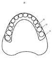
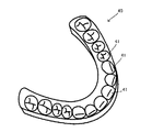
義歯床の設計S22では、口腔内データの取得S21で得た情報に対して必要に応じて変更を加え、義歯床20の形状を設計する。図4には、上顎側の義歯床20を模式的に表した。下顎側の義歯床も上下の差異はあるが、基本的な構成は同様に考えることができる。どちらか一方を作製する場合もあるし、両方作製する場合もある。
義歯床は、人工歯を所定の位置に保持するとともに、口腔粘膜上に有床義歯自体を安定して装着させる機能を有する部材である。従って義歯床20は図4からわかるように、最終的には人工歯30が排列される部位として堤状の盛り上がった堤部21を備えるとともに、この堤部21の頂部に人工歯30の一端が挿入され、人工歯30が固定される凹部22が設けられた形態を備えることになる。ただし、凹部22の位置や形状は排列される人工歯30によって決まるので、当該凹部22の形態は次の人工歯排列の設計S23の後に決まる。
このような義歯床20の設計は公知の方法を用いることができる。
In the denture base design S22, the information obtained in the intraoral data acquisition S21 is changed as necessary, and the shape of the
The denture base is a member having a function of holding the artificial tooth in a predetermined position and stably mounting the denture itself on the oral mucosa. Therefore, as can be seen from FIG. 4, the
Such a
人工歯排列の設計S23では、義歯床の設計S22に対して人工歯30を排列していく。コンピュータのデータベースから人工歯の情報を呼び出して人工歯30を義歯床20に排列する。すなわち、ここまでで取り込んだ情報に基づき、コンピュータの記憶手段に格納されたデータベースから歯列弓に見合った人工歯データを呼び出す。そしてこれを義歯床20の顎堤21上のおおよその位置に配置させたのち位置を微調整する。当該微調整により位置が決まった後、義歯床20に上記説明した凹部22(図4参照)を形成する。このとき、凹部22は、人工歯30を凹部22に挿入し易いように、人工歯30の外形に対して若干大きい形状とされる。
In the artificial tooth arrangement design S23, the
人工歯30は天然の歯牙に代わって機能して天然歯を模して作製された人工の歯牙である。図5(a)に示したように、必要に応じて複数の人工歯30が天然歯と同様に排列される。図5(a)では紙面上が咬合面側、紙面下が義歯床20側であり、紙面左右が排列方向となる。図5(b)には図5(a)にVb−Vbで示した線に沿った人工歯30の断面を示した。これは排列方向に直交する方向の断面である。図5(a)、図5(b)からわかるように、人工歯30のうち、義歯床20側の端部で排列方向とは直交する方向の側面にはアンダーカット部31が設けられている。これにより人工歯30の義歯床20への固定がより強固なものとなる。
The
そして義歯床20に人工歯30が排列されると図6に示したように有床義歯10となる。すなわち、義歯床20の凹部22に人工歯30が配置されて有床義歯10とされる。
When the
咬合プレートの設計S24では、上下の歯列の咬合面間に配置される咬合プレート40を設計する。咬合プレート40は、上下顎の人工歯(又は人工歯と天然歯)の咬合面の咬み合わせ関係が転写された板状の部材である。図7及び図8に説明のための概念図を示した。図7(a)は上下顎の有床義歯10の間に咬合プレート40を配置した場面を斜め方向から見た概念図、図7(b)は正面方向から見た概念図である。また図8には咬合プレート40の斜視図を表した。
In the occlusal plate design S24, the
図7(a)、図7(b)、及び図8からわかるように、咬合プレート40は、歯列に沿った弓状の板であり、上下の歯列の咬合面をその表裏に転写している。従って咬合プレート40には咬合状態における上下歯列の位置関係の情報が含まれる。すなわち、図8からわかるように、咬合プレート40には人工歯30の咬合面側形状に対応した凹部41が形成されている。
As can be seen from FIGS. 7 (a), 7 (b) and 8, the
咬合プレート40の厚さは特に限定されることはないが、当該咬合プレート40のデータに基づいて後述するように実際の咬合プレート140を作製したときに、咬合プレート140の凹部141に人工歯130を差し込んで保持することができるように構成することが好ましい。
The thickness of the
位置決め手段の設計S25では、義歯床20、人工歯30、及び咬合プレート40の位置関係を維持するための位置決め手段を設計する。これにより、後述するように実際に作製された義歯床120に人工歯130を配置するに際して、咬合の状態も含めて精度よく(設計通りに)行うことができる。
In the positioning means design S25, a positioning means for maintaining the positional relationship of the
図9には第一の形態に係る位置決め手段50を説明する図を示した。図9は図7(b)と同じ視点による図である。図9(a)は位置決め手段50を組み合わせたときの姿勢、図9(b)は位置決め手段50を分離したときの姿勢をそれぞれ表している。
FIG. 9 shows a view for explaining the positioning means 50 according to the first embodiment. FIG. 9 is a view from the same viewpoint as FIG. 9A shows the posture when the
位置決め手段50は、図9(a)、図9(b)からわかるように、義歯床接続部材51、咬合プレート接続部材52、及び連結部材53を有して構成されている。ここで義歯床接続部材51は義歯床20に着脱可能に接続する部材であり、咬合プレート接続部材52は咬合プレート40に着脱可能に接続する部材である。そして連結部材53は、義歯床接続部材51と咬合プレート接続部材52とを連結する部材である。本形態では、連結部材52の一部で接続と分離ができるようにジョイント部52aが設けられている。
As can be seen from FIGS. 9A and 9B, the positioning means 50 includes a denture
義歯床接続部材51の義歯床20との接続部、咬合プレート接続部材52の咬合プレート40との接続部、及びジョイント部52aには、突起50a及びこれに対応する穴50bが設けられており、装着時の位置ずれが防止されている。
The connecting portion of the denture
このような位置決め手段50は、患者の咬合状態が再現できる義歯床20、人工歯30の配置になるように形状が設計される。
The positioning means 50 is designed so that the
図10、図11には第二の形態に係る位置決め手段60を説明する図を示した。図10は位置決め手段60が分離した姿勢、図11は位置決め手段60が組み合わされた姿勢である。 10 and 11 are views for explaining the positioning means 60 according to the second embodiment. FIG. 10 shows a posture in which the positioning means 60 is separated, and FIG. 11 shows a posture in which the positioning means 60 is combined.
位置決め手段60は、図10、図11からわかるように、義歯床保持部材61、咬合プレート接続部材62、及び連結部材63を有して構成されている。
ここで、義歯床保持部材61は義歯床20を所定の姿勢に維持する部材である。なお、図10、図11は位置決め手段60を説明するための図であるため、わかり易さの観点から、保持されている義歯床20の表記は省略している。そして図10、図11からわかるように、義歯床保持部材61には義歯床20を保持する凹部61aが設けられ、義歯床20が当該凹部61aに保持されつつ移動及び回動しないように構成されている。
咬合プレート接続部材62は咬合プレート40に一体となって接続する部位である。本形態ではクロス状の部材で、その先端に連結部材63が形成されている。
そして連結部材63は、義歯床保持部材61と咬合プレート接続部材62とを連結する部材である。本形態では、咬合プレート接続部材62の先端に設けられた3つの突起63a、及び義歯床保持部材61に設けられた、当該突起63aが挿入される溝63bにより連結部材63が構成されている。
As can be seen from FIGS. 10 and 11, the positioning means 60 includes a denture
Here, the denture
The occlusal
The connecting
このような位置決め手段60によれば、義歯床保持部材61の凹部61aの内側に義歯床20が配置され、これに対して、図11に示したように、溝63bの内側に突起63aを挿入することで咬合プレート40と義歯床20との位置決めが行われる。
According to such positioning means 60, the
このような位置決め手段60も、位置決め手段50と同様に作用し、設計した人工歯の排列を精度よく実現することができる。 Such positioning means 60 also acts in the same way as the positioning means 50, and can implement the designed artificial tooth arrangement with high accuracy.
図12には第三の形態に係る位置決め手段70を説明する図を示した。当該位置決め手段70では、一群の人工歯列のうち少なくとも1つ、及び、これが差し込まれる義歯床20の凹部22に位置決め手段を設ける例である。図12の例では、人工歯30のうち凹部22の底面に対向する面に位置決め手段70を構成する一方である1つの角柱状の突起70aが配置され、凹部22の底面には突起70aに対応する形状及び位置に窪み70bが設けられている。これによれば、位置決め手段70が設けられた人工歯30では設計した位置及び向きでしか義歯床20の凹部22(位置決め手段70が設けられた凹部)に配置することができない。従って咬合プレートによって位置関係が決定している他の通常の人工歯も位置決め手段70が設けられた人工歯30に追随して正しい位置及び向きで義歯床30の凹部22に配置できる。
また、このような位置決め手段70によれば、位置決め手段70は、最終製品として有床義歯を作製した後には隠蔽されてしまうので、後処理(例えば位置決め手段の除去)をする必要がない。
FIG. 12 shows a view for explaining the positioning means 70 according to the third embodiment. The positioning means 70 is an example in which positioning means is provided in at least one of the group of artificial tooth rows and the
In addition, according to such positioning means 70, the positioning means 70 is concealed after producing the denture as a final product, so that it is not necessary to perform post-processing (for example, removal of the positioning means).
以上のような過程を経て有床義歯の設計S20が終了する。 The platen denture design S20 is completed through the above process.
図1に戻り有床義歯の作製S30について説明する。図3には有床義歯の作製S30の流れを示した。
有床義歯の作製S30では、有床義歯の設計S20で設計された各要素のデータに基づいて実際に各要素を作製し、これらを組み合わせて精度良い有床義歯を作製する工程である。ここでは位置決め手段50による例について説明する。図3からわかるように、有床義歯の作製S30は、要素製作S31、咬合プレートへの人工歯配置S32、義歯床への人工歯配置S33、及び咬合プレート及び位置決め手段の除去S34、を含んでいる。
Returning to FIG. 1, the preparation S30 for a plate denture will be described. FIG. 3 shows the flow of preparation S30 for a plate denture.
In the preparation of a plate denture S30, each element is actually prepared based on the data of each element designed in the plate denture design S20, and a combination of these elements is used to create a precise denture. Here, an example using the positioning means 50 will be described. As can be seen from FIG. 3, the preparation of a denture S30 includes an element production S31, an artificial tooth arrangement S32 on the occlusal plate, an artificial tooth arrangement S33 on the denture base, and an occlusal plate and positioning means removal S34. Yes.
要素作製S31では、有床義歯の設計S20で設計された、義歯床20の形状データ、人工歯30の形状データ、咬合プレート40の形状データ及び位置決め手段50の形状データを個別に抽出し、工作機械へ指令データとして出力し、加工データを受信した工作機械により形状を削り出す。この過程自体は公知の方法により行うことができ、いわゆるCAMによる加工を挙げることができる。
これにより、データとしての義歯床20から実際の義歯床120が作製され、データとしての人工歯30から実際の人工歯130が作製され、データとしての咬合プレート40から実際の咬合プレート140が作製され、データとして位置決め手段50から実際の位置決め手段150(位置決め手段60の場合には位置決め手段160(不図示)、位置決め手段70の場合には位置決め手段170(不図示)。)が作製される。
In the element preparation S31, the shape data of the
Thereby, an
咬合プレートへの人工歯配置S32は、咬合プレート140に人工歯130の咬合面側を挿入して配置する。図13に模式的に表した。咬合プレート140は当該人工歯130の咬合面に基づいて凹部141が形成されているので、その形状が人工歯130と一致することから図13に示したように適切に配置することができる。必要に応じて粘着力の弱い粘着剤等により、ずれない最小限度で咬合プレート140、人工歯130を固定してもよい。
これにより、人工歯130における咬み合わせを含めた位置関係が適切なものとなり、設計に対して精度良い配置を得ることができる。またこの後にも述べるように、人工歯130の排列を1つずつでなく、咬合プレートごと歯列全体で行うことができるので、精度を維持したまま効率よく人工歯の配置をすることが可能である。
In the artificial tooth arrangement S32 on the occlusal plate, the occlusal surface side of the
Thereby, the positional relationship including occlusion in the
義歯床への人工歯配置S33では、咬合プレート140に配置された人工歯130を義歯床120に固定する。本形態では具体的に例えば次のように行われる。図14〜図16に説明のための図を表した。
In the artificial tooth placement S <b> 33 on the denture base, the
始めに、図14に示したように、義歯床120の凹部122に接着材としてのレジン125を配置する。このレジンは人工歯を義歯床に固定する際に用いられる通常のものを用いることができる。
次に本例では先に上顎側の義歯床120に人工歯130を配置する。その際には、図15に示したように、咬合プレート140に配置された人工歯130をまとめて上顎側の義歯床120に押しつけ、それぞれの人工歯130がそれぞれの凹部122に挿入される。そしてこのときには、位置決め手段150の義歯床接続部151が義歯床120に、咬合プレート接続部152が咬合プレート140に接続され、これらが連結部153で連結されている。
その後に下顎側の義歯床120に人工歯130を配置する。その際には図16に示したように、咬合プレート140に配置された人工歯130をまとめて下顎側の義歯床120に押しつけ、それぞれの人工歯130がそれぞれの凹部122に挿入される。そしてこのときには、位置決め手段150の義歯床接続部151が義歯床120に、咬合プレート接続部152が咬合プレート140に接続され、これらが連結部153で連結されている。
First, as shown in FIG. 14, a
Next, in this example, the
Thereafter, the
以上のように、咬合プレート140及び位置決め手段150により、複数の人工歯150の位置関係、人工歯150の義歯床120への位置、及び上下顎の咬合関係が設計に沿って精度よく実現される。
As described above, the
そして最後に図3に表したように、咬合プレート及び位置決め手段の除去S34で、咬合プレート140及び位置決め手段150を除去することにより有床義歯110を得る。
Finally, as shown in FIG. 3, the
なお、位置決め手段160、170が用いられた場合には位置決め手段60、70において説明したように位置決め手段160、170を組み合わせることにより上記の例に倣って同様に有床義歯を得ることができる。ただし、位置決め手段170が用いられた場合には、位置決め手段170の除去は不要である。 When the positioning means 160, 170 are used, the denture can be obtained in the same manner as described above by combining the positioning means 160, 170 as described in the positioning means 60, 70. However, when the positioning means 170 is used, it is not necessary to remove the positioning means 170.
10 有床義歯(データ)
20 義歯床(データ)
30 人工歯(データ)
40 咬合プレート(データ)
50、60、70 位置決め手段(データ)
110 有床義歯
120 義歯床
130 人工歯
140 咬合プレート
150、160、170 位置決め手段
10 Plated denture (data)
20 Denture base (data)
30 Artificial teeth (data)
40 Occlusal plate (data)
50, 60, 70 Positioning means (data)
110
Claims (4)
前記口腔内形状の前記データに基づいて義歯床の形状データを作成する過程と、
前記義歯床の前記形状データに排列される上下顎の人工歯の形状データを作成する過程と、
前記排列された上下顎の人工歯の前記形状データにおける咬合面の形状に対応し、前記上下顎の前記人工歯の前記形状データにおける前記咬合面の咬み合わせ関係が転写された凹部を有する板状の咬合プレートの形状データを作成する過程と、
前記義歯床の前記形状データと前記咬合プレートの前記形状データとの位置を固定する位置決め手段のデータを作成する過程と、を含む、有床義歯の設計方法。 A method of designing a denture on a computer based on intraoral shape data,
A process of creating the shape data of the denture base, based on the data of the intraoral shape,
Creating shape data of upper and lower artificial teeth arranged in the shape data of the denture base;
Wherein corresponding to the shape of the occlusal surface in the shape data of Hairetsu been maxillary and mandibular artificial teeth, a plate shape having the recess occlusal relationship of the occlusal surface in the shape data of the artificial teeth has been transferred the upper and lower jaws The process of creating the shape data of the occlusal plate of
A method for designing a denture, comprising: creating data of positioning means for fixing the position of the shape data of the denture base and the shape data of the occlusal plate .
請求項1に記載の設計方法により有床義歯を設計する過程と、
前記設計に基づいて義歯床、人工歯、咬合プレート、及び位置決め手段を作製する過程と、
作製した前記咬合プレートに作製した前記人工歯を配置する過程と、
前記咬合プレートに配置された前記人工歯を前記義歯床に配置する過程と、を含み、
前記人工歯を前記義歯床に配置する過程では、前記位置決め手段により前記義歯床と前記咬合プレートとの位置関係が決定される、有床義歯の製造方法。 A method for producing a denture,
A process of designing a denture with a design method according to claim 1 ;
Producing a denture base, artificial tooth, occlusal plate, and positioning means based on the design;
A process of placing the artificial teeth prepared on the prepared occlusal plate;
Arranging the artificial teeth arranged on the occlusal plate on the denture base,
In the process of arranging the artificial tooth on the denture base, the positional relationship between the denture base and the occlusal plate is determined by the positioning means.
義歯床と、上下顎の人工歯の咬合面の形状に対応し、前記上下顎の前記人工歯の前記咬合面の咬み合わせ関係が転写された凹部を有する咬合プレートと、を連結する手段である、有床義歯作製用の位置決め手段。 A positioning means used when manufacturing a denture,
Corresponding to the shape of the occlusal surface of the artificial teeth of the upper and lower jaws and an occlusal plate having a recess to which the occlusal relationship of the occlusal surfaces of the artificial teeth of the upper and lower jaws is transferred , Positioning means for preparing dentures.
義歯床の姿勢を保持する義歯床保持部材と、
上下顎の人工歯の咬合面の形状に対応し、前記上下顎の前記人工歯の前記咬合面の咬み合わせ関係が転写された凹部を有する咬合プレートに具備され、前記義歯床保持部材に連結する連結部材と、を備える、有床義歯作製用の位置決め手段。 A positioning means used when manufacturing a denture,
A denture base holding member that holds the posture of the denture base,
Corresponding to the shape of the occlusal surface of the artificial teeth of the upper and lower jaws, the occlusal plate having a recess to which the occlusal relationship of the occlusal surfaces of the artificial teeth of the upper and lower jaws is transferred is connected to the denture base holding member A positioning means for preparing a denture with a connecting member.
Priority Applications (1)
| Application Number | Priority Date | Filing Date | Title |
|---|---|---|---|
| JP2015199660A JP6454627B2 (en) | 2015-10-07 | 2015-10-07 | Method for designing denture, method for producing denture, positioning means |
Applications Claiming Priority (1)
| Application Number | Priority Date | Filing Date | Title |
|---|---|---|---|
| JP2015199660A JP6454627B2 (en) | 2015-10-07 | 2015-10-07 | Method for designing denture, method for producing denture, positioning means |
Publications (3)
| Publication Number | Publication Date |
|---|---|
| JP2017070518A JP2017070518A (en) | 2017-04-13 |
| JP2017070518A5 JP2017070518A5 (en) | 2017-09-07 |
| JP6454627B2 true JP6454627B2 (en) | 2019-01-16 |
Family
ID=58538413
Family Applications (1)
| Application Number | Title | Priority Date | Filing Date |
|---|---|---|---|
| JP2015199660A Active JP6454627B2 (en) | 2015-10-07 | 2015-10-07 | Method for designing denture, method for producing denture, positioning means |
Country Status (1)
| Country | Link |
|---|---|
| JP (1) | JP6454627B2 (en) |
Families Citing this family (3)
| Publication number | Priority date | Publication date | Assignee | Title |
|---|---|---|---|---|
| US10952828B2 (en) | 2017-10-05 | 2021-03-23 | Gc Corporation | Method for designing denture, method for producing denture and positioning means |
| EP3517073A1 (en) * | 2018-01-30 | 2019-07-31 | DGSHAPE Corporation | Method for fabricating denture |
| EP3517074B1 (en) * | 2018-01-30 | 2020-02-19 | DGSHAPE Corporation | Method for fabricating denture base and denture base fabricating kit |
Family Cites Families (3)
| Publication number | Priority date | Publication date | Assignee | Title |
|---|---|---|---|---|
| EP2322115B1 (en) * | 2009-11-16 | 2017-02-15 | Nobel Biocare Services AG | Method for planning and producing a dental prosthesis |
| WO2015055793A1 (en) * | 2013-10-17 | 2015-04-23 | Ivoclar Vivadent Ag | Dental transfer template |
| DE102014118231B3 (en) * | 2014-12-09 | 2016-05-12 | Heraeus Kulzer Gmbh | Method for producing a dental prosthesis with a template |
-
2015
- 2015-10-07 JP JP2015199660A patent/JP6454627B2/en active Active
Also Published As
| Publication number | Publication date |
|---|---|
| JP2017070518A (en) | 2017-04-13 |
Similar Documents
| Publication | Publication Date | Title |
|---|---|---|
| AU2004200418B2 (en) | Device and Method for Manufacturing Dental Prosthesis | |
| US9918810B2 (en) | Method for producing a dental prosthesis with a template | |
| JP6322698B2 (en) | Artificial teeth | |
| US20170348077A1 (en) | Simplified protocol for fixed implant restorations using intra-oral scanning and dental cad/cam | |
| US8876527B2 (en) | Electronic register device for recording jaw movements | |
| US8047846B2 (en) | Preventing interference between tooth models | |
| DK2499990T3 (en) | dental Model | |
| JP6200575B2 (en) | Occlusal harvesting tool for edentulous patients | |
| WO2015194449A1 (en) | Artificial tooth | |
| JP2011110418A (en) | Method of manufacturing denture after implant operation | |
| US20180042709A1 (en) | Preparation of a wax or plastic base for producing a dental prosthesis | |
| JP6454627B2 (en) | Method for designing denture, method for producing denture, positioning means | |
| US20160296305A1 (en) | Artificial tooth and method for producing a denture base | |
| WO2018050836A1 (en) | Calibration members and method for calibrating a virtual articulator | |
| KR20140024363A (en) | Method for producing trays for brackets | |
| US11890151B2 (en) | Method for designing denture, method for producing denture and positioning means | |
| KR101707910B1 (en) | Methods, systems and accessories useful for procedures relating to dental implants | |
| JP6708856B2 (en) | Artificial molar arrangement jig | |
| KR101329732B1 (en) | Mould assembly for fabrication of dental model | |
| JP6802927B2 (en) | Trial denture and trial denture preparation program | |
| JP2022522120A (en) | Denture making assembly, method, and equipment | |
| KR101108627B1 (en) | Plate with reference marker for the image reconstruction of occlusal relationship | |
| WO2019176178A1 (en) | Try-in tool and denture manufacturing method | |
| KR20220143099A (en) | Removable local dentures | |
| WO2018050830A1 (en) | A method for generating a virtual model of a maxillary cast or a mandibular cast in a virtual articulator |
Legal Events
| Date | Code | Title | Description |
|---|---|---|---|
| A521 | Request for written amendment filed |
Free format text: JAPANESE INTERMEDIATE CODE: A523 Effective date: 20170731 |
|
| A621 | Written request for application examination |
Free format text: JAPANESE INTERMEDIATE CODE: A621 Effective date: 20170731 |
|
| A977 | Report on retrieval |
Free format text: JAPANESE INTERMEDIATE CODE: A971007 Effective date: 20180620 |
|
| A131 | Notification of reasons for refusal |
Free format text: JAPANESE INTERMEDIATE CODE: A131 Effective date: 20180703 |
|
| A601 | Written request for extension of time |
Free format text: JAPANESE INTERMEDIATE CODE: A601 Effective date: 20180829 |
|
| A521 | Request for written amendment filed |
Free format text: JAPANESE INTERMEDIATE CODE: A523 Effective date: 20180913 |
|
| TRDD | Decision of grant or rejection written | ||
| A01 | Written decision to grant a patent or to grant a registration (utility model) |
Free format text: JAPANESE INTERMEDIATE CODE: A01 Effective date: 20181204 |
|
| A61 | First payment of annual fees (during grant procedure) |
Free format text: JAPANESE INTERMEDIATE CODE: A61 Effective date: 20181217 |
|
| R150 | Certificate of patent or registration of utility model |
Ref document number: 6454627 Country of ref document: JP Free format text: JAPANESE INTERMEDIATE CODE: R150 |
|
| R250 | Receipt of annual fees |
Free format text: JAPANESE INTERMEDIATE CODE: R250 |
|
| R250 | Receipt of annual fees |
Free format text: JAPANESE INTERMEDIATE CODE: R250 |
|
| R250 | Receipt of annual fees |
Free format text: JAPANESE INTERMEDIATE CODE: R250 |