JP6449660B2 - Printing method and printer using portable label printer - Google Patents
Printing method and printer using portable label printer Download PDFInfo
- Publication number
- JP6449660B2 JP6449660B2 JP2015016809A JP2015016809A JP6449660B2 JP 6449660 B2 JP6449660 B2 JP 6449660B2 JP 2015016809 A JP2015016809 A JP 2015016809A JP 2015016809 A JP2015016809 A JP 2015016809A JP 6449660 B2 JP6449660 B2 JP 6449660B2
- Authority
- JP
- Japan
- Prior art keywords
- printing
- printer
- label
- item
- band
- Prior art date
- Legal status (The legal status is an assumption and is not a legal conclusion. Google has not performed a legal analysis and makes no representation as to the accuracy of the status listed.)
- Active
Links
- 238000000034 method Methods 0.000 title claims description 24
- 238000002372 labelling Methods 0.000 claims description 7
- 238000004519 manufacturing process Methods 0.000 description 7
- 238000011161 development Methods 0.000 description 6
- 229910000831 Steel Inorganic materials 0.000 description 2
- 238000013461 design Methods 0.000 description 2
- 230000002093 peripheral effect Effects 0.000 description 2
- 239000010959 steel Substances 0.000 description 2
- 239000003086 colorant Substances 0.000 description 1
- 238000004040 coloring Methods 0.000 description 1
- 238000010586 diagram Methods 0.000 description 1
- 230000008014 freezing Effects 0.000 description 1
- 238000007710 freezing Methods 0.000 description 1
- 238000010438 heat treatment Methods 0.000 description 1
- 239000004615 ingredient Substances 0.000 description 1
- 238000003825 pressing Methods 0.000 description 1
- 238000012545 processing Methods 0.000 description 1
- 238000010257 thawing Methods 0.000 description 1
- 238000012546 transfer Methods 0.000 description 1
Images


Classifications
-
- B—PERFORMING OPERATIONS; TRANSPORTING
- B41—PRINTING; LINING MACHINES; TYPEWRITERS; STAMPS
- B41K—STAMPS; STAMPING OR NUMBERING APPARATUS OR DEVICES
- B41K1/00—Portable hand-operated devices without means for supporting or locating the articles to be stamped, i.e. hand stamps; Inking devices or other accessories therefor
- B41K1/08—Portable hand-operated devices without means for supporting or locating the articles to be stamped, i.e. hand stamps; Inking devices or other accessories therefor with a flat stamping surface and changeable characters
- B41K1/10—Portable hand-operated devices without means for supporting or locating the articles to be stamped, i.e. hand stamps; Inking devices or other accessories therefor with a flat stamping surface and changeable characters having movable type-carrying bands or chains
-
- B—PERFORMING OPERATIONS; TRANSPORTING
- B41—PRINTING; LINING MACHINES; TYPEWRITERS; STAMPS
- B41K—STAMPS; STAMPING OR NUMBERING APPARATUS OR DEVICES
- B41K3/00—Apparatus for stamping articles having integral means for supporting the articles to be stamped
- B41K3/54—Inking devices
- B41K3/58—Inking devices using ink ribbons, ink sheets, or carbon tape or paper
-
- B—PERFORMING OPERATIONS; TRANSPORTING
- B41—PRINTING; LINING MACHINES; TYPEWRITERS; STAMPS
- B41K—STAMPS; STAMPING OR NUMBERING APPARATUS OR DEVICES
- B41K5/00—Plier-like tools for stamping, or stamping and delivering, tickets or the like
- B41K5/02—Plier-like tools for stamping, or stamping and delivering, tickets or the like with means for varying the image stamped
- B41K5/023—Plier-like tools for stamping, or stamping and delivering, tickets or the like with means for varying the image stamped having type-carrying bands or chains
-
- B—PERFORMING OPERATIONS; TRANSPORTING
- B65—CONVEYING; PACKING; STORING; HANDLING THIN OR FILAMENTARY MATERIAL
- B65C—LABELLING OR TAGGING MACHINES, APPARATUS, OR PROCESSES
- B65C11/00—Manually-controlled or manually-operable label dispensers, e.g. modified for the application of labels to articles
- B65C11/02—Manually-controlled or manually-operable label dispensers, e.g. modified for the application of labels to articles having printing equipment
- B65C11/0205—Manually-controlled or manually-operable label dispensers, e.g. modified for the application of labels to articles having printing equipment modified for the application of labels to articles
- B65C11/021—Manually-controlled or manually-operable label dispensers, e.g. modified for the application of labels to articles having printing equipment modified for the application of labels to articles label feeding from strips
- B65C11/0215—Labels being adhered to a web
-
- B—PERFORMING OPERATIONS; TRANSPORTING
- B65—CONVEYING; PACKING; STORING; HANDLING THIN OR FILAMENTARY MATERIAL
- B65C—LABELLING OR TAGGING MACHINES, APPARATUS, OR PROCESSES
- B65C9/00—Details of labelling machines or apparatus
- B65C9/46—Applying date marks, code marks, or the like, to the label during labelling
Description
本発明は携帯式ラベル印字貼付け機の印字器による印字方法および印字器にかかるもので、とくに少なくとも上下二段印字を行う携帯式ラベル印字貼付け機の印字器による印字方法および印字器に関するものである。
BACKGROUND OF THE
従来から、ラベルによるとくに食品あるいはその食材に関して、製造年月日や消費期限ないし賞味期限、さらには冷凍や解凍、加熱その他の各種処理などの諸項目に関する項目印字、およびその具体的日時など管理用日付に関するデータ印字を行う際に、その項目印字ごとおよびデータ印字ごとに印字器を設けることは、印字器の数が増加および大型化することにつながる結果、携帯式ラベル印字貼付け機に装備する印字器としては、重量および大きさなど制約された範囲内で対応する必要がある。
とくに、少なくとも二種類の独立した項目印字についてそれぞれのデータ印字を一枚のラベルに印字することが要望されている。たとえば、二種類の項目印字およびそれぞれのデータ印字を印字するために、一般的には合計上下四段の印字器を装備する必要があり、携帯式ラベル印字貼付け機としては現実的ではないという問題がある。
Conventionally, for items such as date of manufacture, expiry date, expiration date, and other items such as freezing, thawing, heating, and other various processing, and specific date and time for management, such as food and its ingredients, especially on labels When printing data related to dates, providing a printer for each item print and each data print leads to an increase in the number of printers and an increase in the size of the printer. As a container, it is necessary to cope within a limited range such as weight and size.
In particular, it is desired to print each data print on one label for at least two kinds of independent item prints. For example, in order to print two types of item printing and each data printing, it is generally necessary to equip a total of four upper and lower printers, which is not practical as a portable label printer. There is.
たとえば図6は、ラベル片1への二段印字の典型的な一例を示す説明図であって、図6(1)は、ラベル片1の平面図、図6(2)は、ラベル片1へのたとえば左右四桁の印字を行うためのデータ印字用バンド2の見出し文字記号部分の展開図である。
図6(1)に示すように、ラベル片1には、上下二段の印字器(図示せず)による印字を行って、たとえば消費期限として、上段印字部3に印字した「12月01日」から下段印字部4に印字した「12月02日」を表示している。
For example, FIG. 6 is an explanatory view showing a typical example of two-stage printing on the
As shown in FIG. 6 (1), the
図6(2)に示すように、それぞれのデータ印字用バンド2は、「1、2、・・・9、0」、および「AM」や「PM」その他必要な文字ないし記号を印字可能としている。ただし、データ印字用バンド2は、印字器を装備する携帯式ラベル印字貼付け機の大きさないし重量からの制約から、たとえば13個の文字記号を表示可能としている。
As shown in FIG. 6 (2), each
しかしながら、図6に示したラベル片1への印字による表示では、当然のことながら、「消費期限」の表示を別途行うか、あらかじめこのような表示が消費期限を示しているとの事前の了解が必要である。
However, in the display by printing on the
図7は、この「消費期限」を明示可能としたラベル片5の一例を示す説明図であって、図7(1)は、ラベル片5の平面図、図7(2)は、ラベル片5へのとくに「消費期限」など項目印字を行うための項目印字用バンド6の見出し文字記号部分の展開図である。
なお、項目印字用バンド6は、項目を表示するためにデータ印字用バンド2より幅広にこれを形成しているとともに、データ印字用バンド2と同様に、たとえば13個の文字記号を表示可能としている。
FIG. 7 is an explanatory view showing an example of the
The
図7(1)に示すように、ラベル片5は、上段印字部7、中段印字部8および下段印字部9を有し、上下三段の印字器(図示せず)により、中段印字部8に項目印字用バンド6による「消費期限」の表示を行うとともに、上述のデータ印字用バンド2(図6(2))によって上段印字部7に印字した「12月01日」から下段印字部9に印字した「12月02日」を表示している。
As shown in FIG. 7 (1), the
しかして、とくに食品表示に関しては、「消費期限」ないし「賞味期限」や「製造年月日」などの諸項目に関する項目印字の種類が増加する傾向にあり、この項目印字の数に応じてラベル片1やラベル片5に、上述のようにたとえば少なくとも二種類の独立した項目印字についてそれぞれのデータ印字を一枚のラベルに印字することが要望されている。
In particular, regarding food labeling, there is a tendency for the types of item printing related to various items such as “expiration date” or “expiration date” and “manufacturing date” to increase, and labeling depends on the number of items printed. As described above, for example, at least two types of independent item printing is required to print each data print on the
本発明は以上のような諸問題にかんがみなされたもので、少なくとも上下二段にわたって項目印字およびこれに対応するデータ印字を行うことができる携帯式ラベル印字貼付け機の印字器による印字方法および印字器を提供することを課題とする。 The present invention has been considered in view of the above problems, and a printing method and printer using a printer of a portable label printing and pasting machine capable of performing item printing and data printing corresponding to the upper and lower two stages. It is an issue to provide.
また本発明は、制約がある段数内で、少なくとも二種類の独立した管理日付などのデータ印字およびその項目印字を印字可能な携帯式ラベル印字貼付け機の印字器による印字方法および印字器を提供することを課題とする。 The present invention also provides a printing method and printer using a printer of a portable label printing and pasting machine capable of printing data such as at least two types of independent management dates and their item printing within a limited number of stages. This is the issue.
また本発明は、大きさに制約があるラベル片に必要な情報を印字可能な携帯式ラベル印字貼付け機の印字器による印字方法および印字器を提供することを課題とする。 Another object of the present invention is to provide a printing method and printer using a printer of a portable label printing and pasting machine capable of printing necessary information on a label piece having a size restriction.
すなわち本発明は、印字器として、少なくとも上下二段に設けた第1の印字器及び第2印字器のいずれか一方に項目印字用バンドを設けることに着目したものである。本発明のある態様によれば、帯状の台紙に複数枚のラベル片を仮着したラベル連続体の各ラベル片に印字を行って貼り付ける携帯式ラベル印字貼付け機の印字器による印字方法であって、前記印字器として、少なくとも上下二段に設けた第1の印字器および第2の印字器のいずれか一方に項目印字用バンドを少なくとも二列に設けておくとともに、いずれか他方の前記印字器にデータ印字用バンドを設けておき、前記ラベル片の印字領域を上下左右の四区域に分ける区分け用枠を前記ラベル片にあらかじめ印刷し、前記第1の印字器および前記第2の印字器により、前記印字領域の前記四区域に印字を行う、携帯式ラベル印字貼付け機の印字器による印字方法が提供される。 That is, the present invention pays attention to providing an item printing band on at least one of the first and second printers provided in the upper and lower stages as the printer . According to an aspect of the present invention, there is provided a printing method using a printer of a portable label printing and pasting machine that performs printing on each label piece of a continuous label body in which a plurality of label pieces are temporarily attached to a belt-like mount. In addition, as the printer, at least one of the first printer and the second printer provided in the upper and lower two stages is provided with item printing bands in at least two rows, and the other of the prints A data printing band is provided on the device, and a dividing frame for dividing the printing area of the label piece into four areas, upper, lower, left and right, is printed in advance on the label piece, and the first printer and the second printer By this, the printing method by the printer of a portable label printing sticking machine which performs printing in the four areas of the printing area is provided.
本発明の他の態様によれば、帯状の台紙に複数枚のラベル片を仮着したラベル連続体の各ラベル片に印字を行って貼り付ける携帯式ラベル印字貼付け機の印字器であって、前記印字器として上下三段に設けた、第1の印字器、第2の印字器および第3の印字器の中央部に位置するこの第2の印字器に少なくとも二種類の項目印字に関する項目印字用バンドを設け、前記第2の印字器の上下に位置する前記第1の印字器および第3の印字器により前記項目印字に対応するデータ印字を行い、前記項目印字用バンドは、前記項目印字を上下の二区域に分ける区分け用枠を前記項目印字とともに前記ラベル片に印字可能である、携帯式ラベル印字貼付け機の印字器が提供される。 According to another aspect of the present invention, there is provided a printer for a portable label printing and pasting machine that performs printing on each label piece of a label continuum in which a plurality of label pieces are temporarily attached to a belt-like mount. Item printing related to at least two types of item printing on the first printer, the second printer, and the second printer located at the center of the third printer provided in the upper and lower three stages as the printer A band for printing is provided, and data printing corresponding to the item printing is performed by the first printer and the third printer located above and below the second printer, and the item printing band is used for the item printing. There is provided a printer for a portable label printing and pasting machine capable of printing a labeling frame that divides the upper and lower areas into the label piece together with the item printing .
本発明のその他の態様によれば、帯状の台紙に複数枚のラベル片を仮着したラベル連続体の各ラベル片に印字を行って貼り付ける携帯式ラベル印字貼付け機の印字器による印字方法であって、前記印字器として、上下二段に設けた第1の印字器および第2の印字器の少なくともいずれか一方に項目印字用バンドを、上下または左右の少なくともいずれかの方向に二列に設けておくとともに、前記印字器の、前記項目印字用バンドが設けられていない位置にデータ印字用バンドを設けておき、前記ラベル片の印字領域を、少なくとも上下または、左右の区域に分ける区分け用枠を前記ラベル片にあらかじめ印刷し、前記第1の印字器および前記第2の印字器により、前記印字領域の前記区域に印字を行う、携帯式ラベル印字貼付け機の印字器による印字方法が提供される。According to another aspect of the present invention, a printing method using a printer of a portable label printing and pasting machine that prints and affixes to each label piece of a label continuous body in which a plurality of label pieces are temporarily attached to a belt-like mount. In addition, as the printer, item printing bands are provided in at least one of the first printer and the second printer provided in two upper and lower stages, and are arranged in two rows in at least one of the vertical and horizontal directions. A data printing band is provided at a position of the printer where the item printing band is not provided, and the printing area of the label piece is divided into at least upper and lower or left and right areas. A printer for a portable label printing and pasting machine, in which a frame is printed in advance on the label piece, and printing is performed in the area of the printing area by the first printer and the second printer. Printing method is provided that.
本発明による携帯式ラベル印字貼付け機の印字器による印字方法および印字器においては、印字器として、少なくとも上下二段に設けた第1の印字器および第2の印字器のいずれか一方に項目印字用バンドを設けるとともに、この項目印字用バンドによって二種類の項目印字を可能としたので、各種印字が必要な項目印字およびデータ印字に応じて、ラベル片1への印字を実行可能である。
In the printing method and printer using the printer of the portable label printing and pasting machine according to the present invention, item printing is performed on at least one of the first printer and the second printer provided in the upper and lower two stages as the printer. Since the item band is provided and two types of item printing are made possible by this item printing band, printing on the
とくに第一の発明の携帯式ラベル印字貼付け機の印字器による印字方法によれば、ラベル片の印字領域を上下左右の四区域に分ける区分け用枠をラベル片にあらかじめ印刷し、第1の印字器および第2の印字器により、印字領域の四区域に印字を行うようにしたので、項目印字およびデータ印字をそれぞれの区域を分けて印字することができるとともに、項目印字用バンドを少なくとも二列に設けたため、項目印字の増加に対処可能である。 In particular, according to the printing method by the printer of the portable label printing and pasting machine of the first invention, the dividing frame for dividing the printing area of the label piece into four areas, top, bottom, left and right, is printed in advance on the label piece, and the first printing Since the printer and the second printer perform printing in the four areas of the printing area, the item printing and the data printing can be performed separately in each area, and at least two rows of item printing bands can be printed. Therefore, it is possible to cope with an increase in item printing.
とくに第二の発明の携帯式ラベル印字貼付け機の印字器によれば、印字器として上下三段に設けた、第1の印字器、第2の印字器および第3の印字器の中央部に位置する第2の印字器に少なくとも二種類の項目印字に関する項目印字用バンドを設け、第2の印字器の上下に位置する第1の印字器および第3の印字器により項目印字に対応するデータ印字を行うようにしたので、とくに項目印字の情報が増加してもこれに対応してその表示が可能である。
In particular, according to the printer of the portable label printing and pasting machine of the second invention, the first printer, the second printer, and the third printer provided at the upper and lower three stages as the printer Data corresponding to item printing by the first printer and the third printer located above and below the second printer is provided with at least two types of item printing bands on the second printer located. Since printing is performed, even if the information of item printing increases, it can be displayed correspondingly.
本発明は、印字器として、少なくとも上下二段に設けた第1の印字器および第2の印字器のいずれか一方に二種類の項目印字が可能な項目印字用バンドを設け、各種印字が必要な項目印字およびデータ印字に応じて、ラベル片への印字を実行可能な携帯式ラベル印字貼付け機の印字器による印字方法および印字器を実現した。 In the present invention, an item printing band capable of printing two types of items is provided on at least one of the first and second printers provided in the upper and lower stages as the printer, and various types of printing are required. A printing method and printer using a printer of a portable label printing and pasting machine capable of printing on a label piece according to various item printing and data printing.
つぎに本発明(第一の発明)による携帯式ラベル印字貼付け機の印字器による印字方法および印字器を図1ないし図4にもとづき説明する。ただし、図6および図7と同様の部分には同一符号を付し、その詳述はこれを省略する。
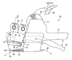
図1は、携帯式ラベル印字貼付け機10の一部切欠き側面図であって、携帯式ラベル印字貼付け機10は、貼付け機本体11と、貼付け機本体11に形成したグリップ12と、貼付け機本体11に設けたレバー軸13に回動可能に設けた操作レバー14と、操作レバー14の先端部に形成したヨーク15に取り付けた上下二段の印字器(たとえば、上段印字用の第1の印字器16、下段印字用の第2の印字器17)と、インキローラー18と、プラテン19と、貼付けローラー20と、を有し、貼付け機本体11の上部にラベル連続体21をロール状に保持して、内部に帯状に供給可能としている。
Next, a printing method and printer using a printer of a portable label printing and pasting machine according to the present invention (first invention) will be described with reference to FIGS. However, the same parts as those in FIGS. 6 and 7 are denoted by the same reference numerals, and detailed description thereof will be omitted.
FIG. 1 is a partially cutaway side view of a portable label printing and
ラベル連続体21は、帯状の台紙22に複数枚のラベル片23(ラベル片2(図6(1)およびラベル片5(図7(1)に相当)を仮着した構成を有している。
携帯式ラベル印字貼付け機10のグリップ12および操作レバー14を握持することにより、第1の印字器16および第2の印字器17がプラテン19方向に下降し、インキローラー18がインキを塗布して、プラテン19上のラベル連続体21のラベル片23に押圧印字する。
グリップ12および操作レバー14の握持開放により貼付け機本体11内の移送機構(図示せず)により、プラテン19の転向稜24において台紙22のみを後方に転向させ、台紙22からラベル片23を剥離して、貼付けローラー20により所定の商品ないし物品(図示せず)に貼り付ける。
The
By gripping the
When the
図2は、第1の印字器16および第2の印字器17の一般的な構成を例示する、図1のII−II線断面図、図3は、図2のIII−III線断面図である。ただし、第1の印字器16および第2の印字器17はいずれも同様の構成を採用可能であるため、第1の印字器16の構成として以下説明する。
第1の印字器16は、印字器本体25と、見出しホィール26および選択軸部材27の間に掛け渡したエンドレスの印字バンド28と、を有し、インジケーター29の矢印指示端30を見出し窓31内で見ながら選択軸32の選択つまみ33を操作することにより、印字バンド28の任意の文字記号を選択可能としている。
すなわち、選択軸32に取り付けた選択ピン34がそれぞれの見出しホィール26の内周方向に形成した内周凹部35に係合しており、見出しホィール26を介して印字バンド28を回動することにより、その見出し文字記号36を見ながらそれぞれの印字文字記号37を選択可能である。
なお、スプリング38により付勢したスチールボール39が、選択軸32に形成した選択溝40に係脱して、選択軸32の移動操作による列方向の印字バンド28の選択を可能とする。
2 is a cross-sectional view taken along the line II-II of FIG. 1 illustrating the general configuration of the
The
That is, the
Note that the steel ball 39 biased by the spring 38 is engaged with and disengaged from the
とくに図3に示すように、見出しホィール26は、弾性支持体41により、見出し文字記号36および印字文字記号37ごとの回動角度でこれを回転および停止可能に支持する。
In particular, as shown in FIG. 3, the heading
選択軸部材27は、スプリング42により付勢した押さえ部材43によりこれを回転および停止可能に支持している。
The
ただし、本発明においては、印字バンド28を各種項目印字およびデータ印字の種類および大きさなどに合わせて、適宜その選択軸32の軸方向における幅および数(列数)、さらには印字するための印字文字記号37を変えている。
すなわち、図2は、その一例を示しており、図2中、右側の四列は、前記データ印字用バンド2(図6(2))と同様の印字バンド28であり、左側の一列は、前記項目印字用バンド6(図7(2))と同様の印字バンド28である。
これらのデータ印字用バンド2および項目印字用バンド6などに代表される印字バンド28は、ラベル連続体21のラベル片23に印字される各種項目印字およびデータ印字の種類および大きさなどに合わせて、データ印字用バンド2および項目印字用バンド6の組み合わせを選択可能である。
However, in the present invention, the width and number (the number of columns) in the axial direction of the
That is, FIG. 2 shows an example thereof. In FIG. 2, the four rows on the right side are the
The
たとえば、図4は、ラベル片23に上下二段に印字する方法の説明図であって、図4(1)は上下二段に印字を行う前のラベル片23を示す平面図、図4(2)は、印字を行うための二列の項目印字用バンド6および四列のデータ印字用バンド2の見出し文字記号部分の展開図、図4(3)は、上下二段に印字を行った状態のラベル片23の平面図である。
For example, FIG. 4 is an explanatory view of a method of printing on the
少なくとも上下二段に設けた第1の印字器16および第2の印字器17のいずれか一方(たとえば第1の印字器16)に、図4(2)に示すように、項目印字用バンド6を少なくとも二列に設けておくとともに、いずれか他方の印字器(たとえば第2の印字器17)にデータ印字用バンド2を設けておく。
At least one of the
また図4(1)に示すように、ラベル片23の印字領域を上下左右の四区域に分ける区分け用枠44(図中、たとえば十字形に描いている)をラベル片23にあらかじめ印刷し、第1の印字器16および第2の印字器17により、印字領域の四区域に印字を行う。
Further, as shown in FIG. 4 (1), a labeling frame 44 (in the figure, for example, drawn in a cross shape) that divides the print area of the
ただし図4(3)に示すように、ラベル片23における上下左右の四区域の上段印字部45および下段印字部46のいずれか一方の段印字部(上段印字部45)における左区域45Aおよび右区域45Bに項目印字用バンド6による二列に項目印字(たとえば、「製造」、「消費期限」)を行う。
さらに、四区域の上段印字部45および下段印字部46のいずれか他方の段印字部(下段印字部46)における左区域46Aおよび右区域46Bに、項目印字に対応するデータ印字(たとえば「製造」が「15日」であり、「消費期限」が「16日」であるとの表示)をデータ印字用バンド2により印字を行う。
However, as shown in FIG. 4 (3), the
Further, data printing corresponding to item printing (for example, “manufacturing”) is performed on the
なお、図4(1)および図4(3)に示すように、項目印字およびデータ印字の少なくともいずれか一方に関連する表示データ(たとえば、当該商品の売出し日が「金曜日」であること)を区分け用枠44にあらかじめ印刷しておくことにより、表示する情報量を増やすことができる。
さらに、区分け用枠44には、上記表示データとしてあらかじめ各種の色を着色したり、任意のデザインをあらかじめ印刷しておき、この着色やデザインによりラベル片23自体を識別可能とし、同じく、表示する情報量を増やすことができる。
As shown in FIG. 4 (1) and FIG. 4 (3), display data related to at least one of item printing and data printing (for example, the sale date of the product is “Friday”). By printing in advance on the sorting
Further, various colors are colored as the display data in advance or an arbitrary design is printed in advance on the sorting
かくして、ラベル片23には、あらかじめ印刷した区分け用枠44により上段印字部45および下段印字部46の区域(左区域45A、右区域45B、左区域46A、右区域46B)を明確に区分けして、それぞれの区域に必要な項目印字およびデータ印字を行うことができる。
さらに、項目印字用バンド6を少なくとも二列に設けているので、項目印字の情報量の増加にも対処可能である。
Thus, the
Furthermore, since the
図5は、ラベル片23に上下三段に印字する第二の発明の説明図であって、図5(1)は、上下三段に印字を行う前のラベル片23を示す平面図、図5(2)は、印字を行うための項目印字用バンド50の見出し文字記号部分の展開図、図5(3)は、上下三段に印字を行った状態のラベル片23の平面図である。
FIG. 5 is an explanatory view of the second invention for printing on the
当該第二の発明においては、上段印字部51に印字するための第1の印字器、中段印字部52に印字するための第2の印字器、および、下段印字部53に印字するための第3の印字器を設けている。
これらの第1の印字器、第2の印字器および第3の印字器は、既述した第1の印字器16(第2の印字器17)における前記項目印字用バンド6と同様の上記項目印字用バンド50、および前記データ印字用バンド2を適宜採用する。
In the second invention, a first printer for printing on the
These first printer, second printer, and third printer are the same items as the
すなわち、中央部に位置する第2の印字器に少なくとも二種類の項目印字に関する項目印字用バンド50を設け、第2の印字器の上下に位置する第1の印字器および第3の印字器にデータ印字用バンド2を設けて、項目印字に対応するデータ印字を行う。
That is, an
ただし、項目印字用バンド50は、項目印字を上下の二区域(上段印字部51、下段印字部53)に分ける区分け用枠54を項目印字(たとえば「製造」、「消費期限」)とともにラベル片23に印字可能である。
However, the
具体的には、とくに図5(2)に示すように、項目印字用バンド50における区分け用枠54は、中段印字部52の左区域52Aに項目印字(たとえば「製造」)とともに印字可能であって左区域52Aの下方に位置する下方線54Aと、右区域52Bに項目印字(たとえば「消費期限」)とともに印字可能であって右区域52Bの上方に位置する上方線54Bと、これら下方線54Aおよび上方線54Bを連結する傾斜線54Cと、を有する。
Specifically, as shown in FIG. 5 (2) in particular, the sorting
かくして、図5(3)に示すように、たとえば二種類の項目印字が可能な項目印字用バンド50を適宜選択して項目印字すなわち、「製造」および「消費期限」さらには区分け用枠印字54Dを中段印字部52に行うとともに、印字したそれぞれの項目印字に応じたデータ印字すなわち、「1201」および「AM10」、ならびに「1201」および「PM10」をそれぞれ上段印字部51ならびに下段印字部53に行うことができる。
したがって、項目印字用バンド50における項目印字の内容を適宜選択組み合わせておくことにより、項目印字の情報量が増加しても、これに対応して必要な印字を的確に実行可能である。
携帯式ラベル印字貼付け機の印字器による印字方法では、ラベル片の上下左右に分けられた四区域の上段印字部および下段印字部のいずれか一方の段印字部における左区域および右区域に項目印字用バンドによる項目印字を行うとともに、四区域の上段印字部および下段印字部のいずれか他方の段印字部における左区域および右区域に、項目印字に対応するデータ印字をデータ印字用バンドにより行うことができる。
項目印字およびデータ印字の少なくともいずれか一方に関連する表示データを区分け用枠にあらかじめ印刷しておくことができる。
Thus, as shown in FIG. 5 (3), for example, an
Therefore, by appropriately selecting and combining the contents of item printing in the
In the printing method using the printer of the portable label printing and pasting machine, items are printed in the left and right areas of one of the upper and lower printing sections of the four areas divided into the upper, lower, left and right sides of the label strip. In addition to performing item printing with a band for data, data printing corresponding to item printing should be performed with the band for data printing in the left and right zones of the other one of the upper and lower printing sections of the four zones. Can do.
Display data related to at least one of item printing and data printing can be printed in advance on the sorting frame.
1 ラベル片(従来、図6(1))
2 データ印字用バンド
3 上段印字部
4 下段印字部
5 ラベル片(従来、図7(1))
6 項目印字用バンド
7 上段印字部
8 中段印字部
9 下段印字部
10 携帯式ラベル印字貼付け機(図1)
11 貼付け機本体
12 グリップ
13 レバー軸
14 操作レバー
15 ヨーク
16 第1の印字器(印字器)
17 第2の印字器(印字器)
18 インキローラー
19 プラテン
20 貼付けローラー
21 ラベル連続体
22 台紙
23 ラベル片(図4(1)、図5(1))
24 転向稜
25 印字器本体
26 見出しホィール
27 選択軸部材
28 印字バンド(印字用バンド2、項目印字用バンド6、50)
29 インジケーター
30 矢印指示端
31 見出し窓
32 選択軸
33 選択つまみ
34 選択ピン
35 内周凹部
36 見出し文字記号
37 印字文字記号
38 スプリング
39 スチールボール
40 選択溝
41 弾性支持体
42 スプリング
43 押さえ部材
44 区分け用枠(図4(1))
45 上段印字部
45A 上段印字部45の左区域
45B 上段印字部45の右区域
46 下段印字部
46A 下段印字部46の左区域
46B 下段印字部46の右区域
50 項目印字用バンド(図5(2))
51 上段印字部(図5(1))
52 中段印字部
52A 中段印字部52の左区域
52B 中段印字部52の右区域
53 下段印字部
54 区分け用枠(図5(2))
54A 区分け用枠54の下方線
54B 区分け用枠54の上方線
54C 区分け用枠54の傾斜線
54D 区分け用枠印字(図5(3))
1 Label piece (conventional, Fig. 6 (1))
2 Band for data printing 3
6 Band for item printing 7 Upper printing section 8 Middle printing section 9
11
17 Second printer (printer)
18
24
29
45
51 Upper printing section (Fig. 5 (1))
52
54A The lower line 54B of the sorting
Claims (5)
前記印字器として、少なくとも上下二段に設けた第1の印字器および第2の印字器のいずれか一方に項目印字用バンドを少なくとも二列に設けておくとともに、
いずれか他方の前記印字器にデータ印字用バンドを設けておき、
前記ラベル片の印字領域を上下左右の四区域に分ける区分け用枠を前記ラベル片にあらかじめ印刷し、
前記第1の印字器および前記第2の印字器により、前記印字領域の前記四区域に印字を行う、携帯式ラベル印字貼付け機の印字器による印字方法。 It is a printing method by a printer of a portable label printing and pasting machine that performs printing on each label piece of a continuous label body in which a plurality of label pieces are temporarily attached to a belt-like mount,
As the printer, at least one of the first printer and the second printer provided in two upper and lower stages is provided with item printing bands in at least two rows,
Either one of the other printers is provided with a data printing band,
A pre-printed frame for dividing the label piece into four areas, upper, lower, left and right, is printed on the label piece,
A printing method using a printer of a portable label printing and pasting machine, wherein printing is performed in the four areas of the printing area by the first printer and the second printer.
前記四区域の前記上段印字部および前記下段印字部のいずれか他方の段印字部における左区域および右区域に、前記項目印字に対応するデータ印字を前記データ印字用バンドにより行う、請求項1記載の携帯式ラベル印字貼付け機の印字器による印字方法。 While performing the item printing by the item printing band in the left area and the right area in any one of the upper stage printing part and the lower stage printing part of the four areas divided into the upper, lower, left and right of the label piece,
The left area and right area in any other stage printing section of the upper printing unit and the lower printing unit of the four zones, performs data printing corresponding to the item printed by the data print band, according to claim 1, wherein Printing method using a portable label printing and pasting machine.
前記印字器として上下三段に設けた、第1の印字器、第2の印字器および第3の印字器の中央部に位置するこの第2の印字器に少なくとも二種類の項目印字に関する項目印字用バンドを設け、
前記第2の印字器の上下に位置する前記第1の印字器および第3の印字器により前記項目印字に対応するデータ印字を行い、
前記項目印字用バンドは、前記項目印字を上下の二区域に分ける区分け用枠を前記項目印字とともに前記ラベル片に印字可能である、携帯式ラベル印字貼付け機の印字器。 It is a printer of a portable label printing and pasting machine that performs printing and pasting on each label piece of a continuous label body in which a plurality of label pieces are temporarily attached to a belt-like mount,
Item printing related to at least two types of item printing on the first printer, the second printer, and the second printer located at the center of the third printer provided in the upper and lower three stages as the printer Provided a band for
Performing data printing corresponding to the item printing by the first and third printers located above and below the second printer ;
The item printing band is a printer for a portable label printing and pasting machine capable of printing a labeling frame for dividing the item printing into two upper and lower areas together with the item printing on the label piece .
前記印字器として、上下二段に設けた第1の印字器および第2の印字器の少なくともいずれか一方に項目印字用バンドを、上下または左右の少なくともいずれかの方向に二列に設けておくとともに、 As the printer, item printing bands are provided in at least one of the first printer and the second printer provided in two upper and lower stages in two rows in at least one of the upper and lower directions and the left and right directions. With
前記印字器の、前記項目印字用バンドが設けられていない位置にデータ印字用バンドを設けておき、 A data printing band is provided at a position of the printer where the item printing band is not provided,
前記ラベル片の印字領域を、少なくとも上下または、左右の区域に分ける区分け用枠を前記ラベル片にあらかじめ印刷し、 A labeling frame that divides the print area of the label piece into at least upper and lower or left and right areas is pre-printed on the label piece,
前記第1の印字器および前記第2の印字器により、前記印字領域の前記区域に印字を行う、携帯式ラベル印字貼付け機の印字器による印字方法。 A printing method using a printer of a portable label printing and pasting machine, wherein printing is performed in the area of the printing area by the first printer and the second printer.
Priority Applications (3)
| Application Number | Priority Date | Filing Date | Title |
|---|---|---|---|
| JP2015016809A JP6449660B2 (en) | 2015-01-30 | 2015-01-30 | Printing method and printer using portable label printer |
| PCT/JP2016/051851 WO2016121647A1 (en) | 2015-01-30 | 2016-01-22 | Printing method by printer of portable label printing/sticking machine, and printer |
| US15/510,413 US10414184B2 (en) | 2015-01-30 | 2016-01-22 | Print method using printer module of portable label printing/sticking machine and printer module |
Applications Claiming Priority (1)
| Application Number | Priority Date | Filing Date | Title |
|---|---|---|---|
| JP2015016809A JP6449660B2 (en) | 2015-01-30 | 2015-01-30 | Printing method and printer using portable label printer |
Publications (3)
| Publication Number | Publication Date |
|---|---|
| JP2016140999A JP2016140999A (en) | 2016-08-08 |
| JP2016140999A5 JP2016140999A5 (en) | 2017-03-16 |
| JP6449660B2 true JP6449660B2 (en) | 2019-01-09 |
Family
ID=56543260
Family Applications (1)
| Application Number | Title | Priority Date | Filing Date |
|---|---|---|---|
| JP2015016809A Active JP6449660B2 (en) | 2015-01-30 | 2015-01-30 | Printing method and printer using portable label printer |
Country Status (3)
| Country | Link |
|---|---|
| US (1) | US10414184B2 (en) |
| JP (1) | JP6449660B2 (en) |
| WO (1) | WO2016121647A1 (en) |
Family Cites Families (12)
| Publication number | Priority date | Publication date | Assignee | Title |
|---|---|---|---|---|
| US1362329A (en) * | 1919-04-09 | 1920-12-14 | Advance Mfg & Supply Company | Band-wheel for hand-stamps |
| JPS599420B2 (en) * | 1975-09-05 | 1984-03-02 | (株) サト−研究所 | Constant pressure mechanism in hand labeler |
| US4113544A (en) * | 1975-12-20 | 1978-09-12 | Kabushiki Kaisha Sato Kenkyusho | Portable label printing and applying machine |
| US4075944A (en) * | 1976-04-30 | 1978-02-28 | Primark Corporation | Self-indexing label marking gun |
| JP3414900B2 (en) * | 1995-07-24 | 2003-06-09 | 株式会社新盛インダストリーズ | Fixing device for setting print sequence in handler labeler |
| DE10041522A1 (en) * | 2000-08-24 | 2002-03-07 | Meto International Gmbh | printing unit |
| JP4056241B2 (en) * | 2001-10-26 | 2008-03-05 | 株式会社キングジム | Tape printer |
| US20070029820A1 (en) * | 2005-08-02 | 2007-02-08 | Navatech Company Limited | Tamper evident seal assembly |
| US7621216B2 (en) * | 2006-06-21 | 2009-11-24 | Avery Dennison Retail Information Services Llc | Labeler and endless printing band for date-coding system |
| WO2008075652A1 (en) * | 2006-12-20 | 2008-06-26 | Kabushiki Kaisha Sato | Thermally active label, and printer for the thermally active label |
| JP5712638B2 (en) * | 2011-01-27 | 2015-05-07 | 株式会社寺岡精工 | Mountless label printer |
| JP5038518B2 (en) | 2011-04-26 | 2012-10-03 | サトーホールディングス株式会社 | Print selection device for printer |
-
2015
- 2015-01-30 JP JP2015016809A patent/JP6449660B2/en active Active
-
2016
- 2016-01-22 US US15/510,413 patent/US10414184B2/en active Active
- 2016-01-22 WO PCT/JP2016/051851 patent/WO2016121647A1/en active Application Filing
Also Published As
| Publication number | Publication date |
|---|---|
| WO2016121647A1 (en) | 2016-08-04 |
| US10414184B2 (en) | 2019-09-17 |
| US20170282624A1 (en) | 2017-10-05 |
| JP2016140999A (en) | 2016-08-08 |
Similar Documents
| Publication | Publication Date | Title |
|---|---|---|
| US7170538B2 (en) | Thermal and inkjet printer | |
| CN100415531C (en) | Information processing apparatus, information processing method and program | |
| CN202383928U (en) | Three-layer adhesive label | |
| EP2325090B1 (en) | Composite label web roll | |
| JP2010514642A (en) | Auxiliary equipment for labeling machines | |
| JP6449660B2 (en) | Printing method and printer using portable label printer | |
| DE19912529A1 (en) | Device for documenting overheating of cold store or deep-frozen products; has layer of thermo-indicator that undergoes irreversible reaction to produce colour change, or display symbol or message | |
| JP5712638B2 (en) | Mountless label printer | |
| EP1201444A3 (en) | A label printer | |
| US1957167A (en) | Coupon ticket printing machine | |
| JP6147986B2 (en) | Price changing label affixing sheet and price changing method using the same | |
| US2790386A (en) | Rotary printing device | |
| CN203825947U (en) | Logistic waybill label | |
| MY166571A (en) | Method for manufacturing the tab of a can so as to be able to use the end thereof for promotional use | |
| KR20060113945A (en) | Variable data heat transfer label, method of making and using same | |
| US3408929A (en) | Merchandising marker | |
| CN201130450Y (en) | Infant mathematics machine | |
| JP4560759B2 (en) | Manufacturing method of sleeve box for golf ball | |
| TWM512002U (en) | Improved label sticker and roll type label sticker | |
| US20230271752A1 (en) | Multipack of several containers held together by adhesive | |
| JP3152914U (en) | Coupon sheet | |
| DE202022001682U1 (en) | Office Chocolate Characters | |
| JP2006334978A (en) | Label printer | |
| JP2018103489A (en) | Identification code printer, identification code printing method, label and packing material | |
| JP2016140999A5 (en) |
Legal Events
| Date | Code | Title | Description |
|---|---|---|---|
| A521 | Request for written amendment filed |
Free format text: JAPANESE INTERMEDIATE CODE: A523 Effective date: 20170213 |
|
| A621 | Written request for application examination |
Free format text: JAPANESE INTERMEDIATE CODE: A621 Effective date: 20171205 |
|
| A131 | Notification of reasons for refusal |
Free format text: JAPANESE INTERMEDIATE CODE: A131 Effective date: 20180807 |
|
| A521 | Request for written amendment filed |
Free format text: JAPANESE INTERMEDIATE CODE: A523 Effective date: 20181001 |
|
| RD02 | Notification of acceptance of power of attorney |
Free format text: JAPANESE INTERMEDIATE CODE: A7422 Effective date: 20181001 |
|
| TRDD | Decision of grant or rejection written | ||
| A01 | Written decision to grant a patent or to grant a registration (utility model) |
Free format text: JAPANESE INTERMEDIATE CODE: A01 Effective date: 20181127 |
|
| A61 | First payment of annual fees (during grant procedure) |
Free format text: JAPANESE INTERMEDIATE CODE: A61 Effective date: 20181206 |
|
| R150 | Certificate of patent or registration of utility model |
Ref document number: 6449660 Country of ref document: JP Free format text: JAPANESE INTERMEDIATE CODE: R150 |
|
| R250 | Receipt of annual fees |
Free format text: JAPANESE INTERMEDIATE CODE: R250 |
|
| R250 | Receipt of annual fees |
Free format text: JAPANESE INTERMEDIATE CODE: R250 |
|
| R250 | Receipt of annual fees |
Free format text: JAPANESE INTERMEDIATE CODE: R250 |