JP6446189B2 - Sound equipment - Google Patents

Sound equipment Download PDF

Info

Publication number
JP6446189B2
JP6446189B2 JP2014132670A JP2014132670A JP6446189B2 JP 6446189 B2 JP6446189 B2 JP 6446189B2 JP 2014132670 A JP2014132670 A JP 2014132670A JP 2014132670 A JP2014132670 A JP 2014132670A JP 6446189 B2 JP6446189 B2 JP 6446189B2
Authority
JP
Japan
Prior art keywords
headrest
acoustic
sound
backrest
cushion
Prior art date
Legal status (The legal status is an assumption and is not a legal conclusion. Google has not performed a legal analysis and makes no representation as to the accuracy of the status listed.)
Active
Application number
JP2014132670A
Other languages
Japanese (ja)
Other versions
JP2016011005A5 (en
JP2016011005A (en
Inventor
高田 直樹
直樹 高田
文彬 中島
文彬 中島
貴夫 石川
貴夫 石川
隆彦 長澤
隆彦 長澤
康行 伊藤
康行 伊藤
Current Assignee (The listed assignees may be inaccurate. Google has not performed a legal analysis and makes no representation or warranty as to the accuracy of the list.)
Tachi S Co Ltd
Faurecia Clarion Electronics Co Ltd
Original Assignee
Clarion Co Ltd
Tachi S Co Ltd
Priority date (The priority date is an assumption and is not a legal conclusion. Google has not performed a legal analysis and makes no representation as to the accuracy of the date listed.)
Filing date
Publication date
Application filed by Clarion Co Ltd, Tachi S Co Ltd filed Critical Clarion Co Ltd
Priority to JP2014132670A priority Critical patent/JP6446189B2/en
Priority to PCT/JP2015/064052 priority patent/WO2015198745A1/en
Priority to US15/307,889 priority patent/US10328831B2/en
Priority to EP15812128.5A priority patent/EP3162622B1/en
Priority to CN201580030026.3A priority patent/CN106414167B/en
Publication of JP2016011005A publication Critical patent/JP2016011005A/en
Publication of JP2016011005A5 publication Critical patent/JP2016011005A5/ja
Application granted granted Critical
Publication of JP6446189B2 publication Critical patent/JP6446189B2/en
Active legal-status Critical Current
Anticipated expiration legal-status Critical

Links

Images

Description

本発明は、音響装置に関する。   The present invention relates to an acoustic device.

従来、シートのヘッドレストのケース部材に箱型のスピーカーを内蔵した音響装置が知られている(例えば、特許文献1参照)。   Conventionally, an acoustic device in which a box-shaped speaker is built in a case member of a headrest of a seat is known (for example, see Patent Document 1).

特開2009−247388号公報JP 2009-247388 A

しかし、上記従来の音響装置では、スピーカーの箱状のエンクロージャーがヘッドレストの内側に組み込まれるため、ヘッドレストとしてのサイズの制約から大型のエンクロージャーを用いることができず、低音の再生能力が低くなっている。
本発明は、上述した事情に鑑みてなされたものであり、ヘッドレストにスピーカーを備えた音響装置において、簡単な構造で低音の再生能力を向上できるようにすることを目的とする。
However, in the above-described conventional acoustic device, since the box-shaped enclosure of the speaker is incorporated inside the headrest, a large enclosure cannot be used due to the size restriction as the headrest, and the low-frequency sound reproduction capability is low. .
The present invention has been made in view of the above-described circumstances, and an object of the present invention is to improve a bass reproduction capability with a simple structure in an acoustic device including a speaker on a headrest.

上記目的を達成するため、本発明は、ヘヘッドレスト本体の芯となる密閉構造の芯材と、当該芯材に配置される音響スピーカーと、前記芯材を貫通する中空のヘッドレストステーとを有し、前記ヘッドレスト本体は前記ヘッドレストステーがシートの背もたれ部に挿入されて前記背もたれ部に接続され、前記ヘッドレストステーは、中空部を介して前記芯材の内部空間と前記背もたれ部の内部とを連通させ、前記ヘッドレストステーは、空気の連通孔を備え、前記連通孔の内、前記芯材の内部空間で開口する前記連通孔は、前記音響スピーカーの後方に位置するとともに、前記ヘッドレストステーの上方に開口することを特徴とする。
また、本発明は、前記連通孔の内、前記背もたれ部内で開口する前記連通孔は、前記ヘッドレストステーのパイプ形状の端または側面に設けられ、前記パイプ形状の前記側面に前記連通孔が設けられる場合、前記背もたれ部内の前記パイプ形状の前記端は塞がれ、前記側面の前記連通孔を空気が流通し、前記パイプ形状の前記側面に前記連通孔が設けられない場合、前記背もたれ部内の前記パイプ形状の前記端は塞がれず、前記端を空気が流通することを特徴とする。
In order to achieve the above object, the present invention includes a sealed core material serving as a core of a headrest main body, an acoustic speaker disposed on the core material, and a hollow headrest stay penetrating the core material. The headrest body has the headrest stay inserted into the backrest portion of the seat and connected to the backrest portion, and the headrest stay communicates the internal space of the core member with the interior of the backrest portion through a hollow portion. The headrest stay includes an air communication hole, and the communication hole that opens in the internal space of the core member is located behind the acoustic speaker and opens above the headrest stay. vinegar Rukoto and features.
Further, according to the present invention, the communication hole that opens in the backrest portion of the communication hole is provided in a pipe-shaped end or side surface of the headrest stay, and the communication hole is provided in the side surface of the pipe shape. The pipe-shaped end in the backrest portion is closed, air flows through the communication hole in the side surface, and the communication hole is not provided in the pipe-shaped side surface, the inside of the backrest portion The end of the pipe shape is not blocked, and air flows through the end .

また、本発明は、前記背もたれ部の内部に設けられる拡張エンクロージャーを備え、前記ヘッドレストステーは、前記拡張エンクロージャーに連通することを特徴とする。
さらに、本発明は、前記拡張エンクロージャーは、前記背もたれ部の前面側へ空気を放出させるポートを備えることを特徴とする。
また、本発明は、前記音響スピーカーは左右一対で設けられ、前記ヘッドレストステーは、前記音響スピーカーに近接する位置に左右一対で設けられることを特徴とする。
The present invention also includes an expansion enclosure provided inside the front dress resting portion, the headrest stay is characterized by communicating with the expansion enclosure.
Furthermore, the present invention is characterized in that the expansion enclosure includes a port for releasing air to the front side of the backrest.
Further, the present invention is characterized in that the acoustic speakers are provided as a pair of left and right, and the headrest stay is provided as a pair of left and right at a position close to the acoustic speaker.

本発明によれば、ヘッドレストにスピーカーを備えた音響装置において、簡単な構造で低音の再生能力を向上できる。   ADVANTAGE OF THE INVENTION According to this invention, the reproduction | regeneration capability of a bass can be improved with a simple structure in the audio equipment which provided the speaker with the headrest.

本発明の第1の実施の形態に係るヘッドレスト装置を示す斜視図である。It is a perspective view showing a headrest device concerning a 1st embodiment of the present invention. ヘッドレスト装置を示す斜視図である。It is a perspective view which shows a headrest apparatus. ヘッドレスト本体を分解した斜視図である。It is the perspective view which decomposed | disassembled the headrest main body. ヘッドレスト装置の縦断面図である。It is a longitudinal cross-sectional view of a headrest apparatus. ヘッドレスト装置の縦断面図である。It is a longitudinal cross-sectional view of a headrest apparatus. ヘッドレスト装置の横断面図である。It is a cross-sectional view of the headrest device. 図5における下部クロスメンバの周辺部の拡大図である。It is an enlarged view of the peripheral part of the lower cross member in FIG. ヘッドレスト装置の音のボリュームと制御基板の温度との関係を示す図表である。It is a graph which shows the relationship between the volume of the sound of a headrest apparatus, and the temperature of a control board. 第2の実施の形態におけるフレームの上部を示す正面図である。It is a front view which shows the upper part of the flame | frame in 2nd Embodiment. のZ矢視図である。FIG. 10 is a Z arrow view of FIG. 9 . 第3の実施の形態におけるフレームの構成を示す図である。It is a figure which shows the structure of the flame | frame in 3rd Embodiment. 第4の実施の形態に係るシートの構造を示す模式図である。It is a schematic diagram which shows the structure of the sheet | seat which concerns on 4th Embodiment. シートの内部構成を示す図である。It is a figure which shows the internal structure of a sheet | seat.

以下、本発明の実施の形態について図面を参照しながら以下に説明する。
[第1の実施の形態]
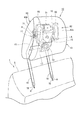
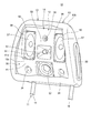
図1及び図2は、本発明の第1の実施の形態に係るヘッドレスト装置10を示す斜視図である。図1では、後述するクッション芯材12の図示が省略されている。図2では、後述するクッション13の前面の図示が省略されている。
ヘッドレスト装置10(音響装置)は、車室内に配置される乗員用のシート1に設けられるものである。上記車室としては、例えば、自動車、電車、飛行機及び船舶等の車室が挙げられるが、本実施の形態では、自動車の前部座席であって運転者が着座するシート1に設けられるヘッドレスト装置10を例に挙げて説明する。自動車としては、通常の四輪車の他、例えば、側面のドアを備えていない小型の電気自動車が挙げられる。
シート1は、運転者(着座者)が着座する座面部(不図示)と、座面部の後端から僅かに後ろに傾斜した姿勢で上方に延在する背もたれ部5と、この背もたれ部5の上端に取り付けられるヘッドレスト装置10とを備える。
Hereinafter, embodiments of the present invention will be described with reference to the drawings.
[First Embodiment]
FIG.1 and FIG.2 is a perspective view which shows the headrest apparatus 10 which concerns on the 1st Embodiment of this invention. In FIG. 1, illustration of a cushion core member 12 to be described later is omitted. In FIG. 2, illustration of the front surface of the cushion 13 described later is omitted.
The headrest device 10 (acoustic device) is provided on an occupant seat 1 disposed in a vehicle interior. Examples of the vehicle compartment include vehicle compartments such as automobiles, trains, airplanes, and ships. In this embodiment, a headrest device provided on a seat 1 that is a front seat of an automobile and on which a driver sits. 10 will be described as an example. As an automobile, in addition to a normal four-wheeled vehicle, for example, a small electric vehicle not provided with a side door can be cited.
The seat 1 includes a seat surface portion (not shown) on which a driver (seater) sits, a backrest portion 5 that extends upward in a posture slightly tilted rearward from the rear end of the seat surface portion, and the backrest portion 5. And a headrest device 10 attached to the upper end.

ヘッドレスト装置10は、音響スピーカー50及び音響マイク51を備えるとともに、近距離無線通信によりヘッドレスト装置10を携帯端末等の他の機器(不図示)と連携可能とする通信部(不図示)を備える。上記他の機器としては、例えば、携帯電話、スマートフォン、タブレット端末、カーオーディオ、及びカーナビゲーションシステム等が挙げられる。上記近距離無線通信としては、例えば、Bluetooth(近距離無線通信規格:登録商標)が挙げられる。なお、ヘッドレスト装置10と上記他の機器とは、近距離無線通信に限らず、例えば有線によって接続することも可能である。   The headrest device 10 includes an acoustic speaker 50 and an acoustic microphone 51, and also includes a communication unit (not illustrated) that enables the headrest device 10 to cooperate with other devices (not illustrated) such as a mobile terminal through short-range wireless communication. As said other apparatus, a mobile telephone, a smart phone, a tablet terminal, a car audio, a car navigation system etc. are mentioned, for example. Examples of the short-range wireless communication include Bluetooth (Near-Range Wireless Communication Standard: registered trademark). The headrest device 10 and the other devices can be connected not only by short-range wireless communication but also by wire, for example.

ヘッドレスト装置10は、上記他の機器と連携した状態では、他の機器から読み出されたコンテンツの音声データや、車両を目的地まで誘導するための誘導音声データなどを、音響スピーカー50から音声出力する。また、着座者は、ヘッドレスト装置10が上記他の機器と連携した状態では、音響マイク51で集音された音声をボイスコマンドとして他の機器を操作したり、音響マイク51を介してハンズフリーで通話したりすることができる。   In a state in which the headrest device 10 is linked to the other device, the sound speaker 50 outputs sound data of content read from the other device, guidance sound data for guiding the vehicle to the destination, and the like from the acoustic speaker 50. To do. In addition, in the state where the headrest device 10 is linked to the other device, the seated person can operate the other device by using the voice collected by the acoustic microphone 51 as a voice command, or hands-free via the acoustic microphone 51. You can make a call.

ヘッドレスト装置10は、ヘッドレスト装置10の骨組みとしてのフレーム11(フレーム部材)と、フレーム11に連結されるヘッドレスト本体としてのクッション芯材12(芯材)と、クッション芯材12の周囲を覆うように設けられ、着座者の頭部を受けるクッション13とを備える。本第1の実施の形態では、ヘッドレスト本体は、クッション芯材12であるが、ヘッドレスト本体は、最外層のクッション13によって覆われるものであれば良く、クッション芯材12に加えて他の部材を含んでいても良い。   The headrest device 10 covers a frame 11 (frame member) as a skeleton of the headrest device 10, a cushion core material 12 (core material) as a headrest main body connected to the frame 11, and a periphery of the cushion core material 12. And a cushion 13 for receiving the head of the seated person. In the first embodiment, the headrest body is the cushion core material 12, but the headrest body only needs to be covered by the outermost cushion 13, and other members in addition to the cushion core material 12 are used. It may be included.

図3は、クッション芯材12及びフレーム11を分解した斜視図である。
フレーム11は、金属製であり、パイプ材及び板材を溶接して一体に形成される。フレーム11は、例えば鉄鋼材料製である。
フレーム11は、左右方向に並んで上下方向に延在する一対のヘッドレストステー15,15と、ヘッドレストステー15,15の上端部を左右に連結する上部クロスメンバ16と、上部クロスメンバ16の下方でヘッドレストステー15,15を左右に連結する下部クロスメンバ17とを備える。
FIG. 3 is an exploded perspective view of the cushion core member 12 and the frame 11.
The frame 11 is made of metal and is integrally formed by welding a pipe material and a plate material. The frame 11 is made of, for example, a steel material.
The frame 11 includes a pair of headrest stays 15, 15 extending in the vertical direction side by side in the left-right direction, an upper cross member 16 that connects the upper ends of the headrest stays 15, 15 to the left and right, And a lower cross member 17 that connects the headrest stays 15 and 15 to the left and right.

ヘッドレストステー15,15は、中空の丸パイプ状に形成されており、その全長に亘って断面略円形の中空部70を備える。ヘッドレストステー15,15は、背もたれ部5と略平行に上方へ延びるステー部18,18と、ステー部18,18の上端で前方へ屈曲してやや前傾した姿勢で上方に延びる内部フレーム部19,19とを備える。
内部フレーム部19,19は、クッション13の内側でヘッドレスト装置10の内部に位置する。ステー部18,18は、背もたれ部5の上面に形成された取り付け孔部(不図示)に挿入されてシート1に固定される。ヘッドレスト装置10は、前記取り付け孔部へのステー部18,18の挿入深さを調節することで、着座者の体格等に合わせて取り付けの高さ位置を変更可能に構成されている。
The headrest stays 15 and 15 are formed in a hollow round pipe shape, and include a hollow portion 70 having a substantially circular cross section over the entire length thereof. The headrest stays 15, 15 include stay portions 18, 18 that extend upward substantially parallel to the backrest portion 5, and an internal frame portion 19 that extends upward in a slightly forward tilted posture by bending forward at the upper ends of the stay portions 18, 18. 19.
The inner frame portions 19 and 19 are located inside the headrest device 10 inside the cushion 13. The stay portions 18, 18 are inserted into attachment holes (not shown) formed on the upper surface of the backrest portion 5 and fixed to the seat 1. The headrest device 10 is configured such that the height position of the attachment can be changed according to the physique of the seated person by adjusting the insertion depth of the stay portions 18 and 18 into the attachment hole portion.

クッション芯材12は、後面が開口した略箱型の前側ケース30と、前面が開口した略箱型の後側ケース31とを互いの開口で合わせることで、密閉された箱状に形成されている。クッション芯材12は、上下方向及び左右方向に長く、前後方向に短い略直方体形状に形成されている。前側ケース30及び後側ケース31は、樹脂成型品であり、例えば、ABS樹脂やポリプロピレン樹脂などの樹脂材料により構成される。
前側ケース30及び後側ケース31は、開口の周縁部に合わせ面32,33をそれぞれ有する。詳細には、前側ケース30の合わせ面32に形成された溝部32aに後側ケース31の合わせ面33が嵌まることで、合わせ面32,33は閉じられる。合わせ面32,33の間には、枠状のパッキン(不図示)が介装されることで密閉性が向上されている。また、合わせ面32,33は、例えば、超音波溶着によって接合して密閉されても良い。
The cushion core member 12 is formed in a sealed box shape by combining a substantially box-shaped front case 30 with an open rear surface and a substantially box-shaped rear case 31 with an open front surface at each other opening. Yes. The cushion core material 12 is formed in a substantially rectangular parallelepiped shape that is long in the vertical direction and the left-right direction and short in the front-back direction. The front case 30 and the rear case 31 are resin molded products, and are made of, for example, a resin material such as ABS resin or polypropylene resin.
The front case 30 and the rear case 31 have mating surfaces 32 and 33 at the peripheral edge of the opening, respectively. Specifically, the mating surfaces 32 and 33 are closed by fitting the mating surface 33 of the rear case 31 into the groove 32 a formed on the mating surface 32 of the front case 30. Between the mating surfaces 32 and 33, a frame-like packing (not shown) is interposed to improve the sealing performance. Further, the mating surfaces 32 and 33 may be sealed by joining, for example, by ultrasonic welding.

上部クロスメンバ16及び下部クロスメンバ17の前面には、固定孔部20が複数設けられ、固定孔部20には、前側ケース30をフレーム11に固定する前側ケース固定ボルト21(図5)が締結される。上部クロスメンバ16及び下部クロスメンバ17の後面には、固定孔部22が複数設けられ、固定孔部22には、後側ケース31をフレーム11に固定する後側ケース固定ボルト23(図4)が締結される。
前側ケース30は、前側ケース固定ボルト21が挿通される固定部34を複数備える。後側ケース31は、後側ケース固定ボルト23が挿通される固定部35を複数備える。詳細には、固定部34,35は、クッション芯材12の内側へ窪む有底円筒状に形成されており、前側ケース固定ボルト21及び後側ケース固定ボルト23はこの円筒形状の底部に挿通される。
A plurality of fixing hole portions 20 are provided in front of the upper cross member 16 and the lower cross member 17, and a front case fixing bolt 21 (FIG. 5) for fixing the front case 30 to the frame 11 is fastened to the fixing hole portion 20. Is done. A plurality of fixing hole portions 22 are provided on the rear surfaces of the upper cross member 16 and the lower cross member 17, and a rear case fixing bolt 23 (FIG. 4) that fixes the rear case 31 to the frame 11 is provided in the fixing hole portion 22. Is concluded.
The front case 30 includes a plurality of fixing portions 34 through which the front case fixing bolts 21 are inserted. The rear case 31 includes a plurality of fixing portions 35 through which the rear case fixing bolts 23 are inserted. Specifically, the fixing portions 34 and 35 are formed in a bottomed cylindrical shape that is recessed toward the inside of the cushion core member 12, and the front case fixing bolt 21 and the rear case fixing bolt 23 are inserted into the cylindrical bottom portion. Is done.

前側ケース30及び後側ケース31は、フレーム11を前後から挟むとともに、合わせ面32,33同士が嵌まるように配置され、外側から設けられる前側ケース固定ボルト21及び後側ケース固定ボルト23によってフレーム11に固定される。すなわち、フレーム11の上部は、中空に形成されたクッション芯材12の内部に位置する。
クッション芯材12は、ステー部18,18が下方へ貫通するステー用貫通孔36,36を下部に備える。ステー用貫通孔36,36とステー部18,18との間には、シール部材(不図示)が設けられ、クッション芯材12内部の密閉性が確保される。
The front case 30 and the rear case 31 are arranged such that the frame 11 is sandwiched from the front and the rear and the mating surfaces 32 and 33 are fitted to each other, and the front case fixing bolt 21 and the rear case fixing bolt 23 provided from the outside are used as the frame. 11 is fixed. That is, the upper part of the frame 11 is located inside the cushion core member 12 formed in a hollow shape.
The cushion core material 12 includes stay through holes 36 and 36 in the lower part through which the stay portions 18 and 18 penetrate downward. A seal member (not shown) is provided between the stay through-holes 36 and 36 and the stay portions 18 and 18, and the inside of the cushion core material 12 is secured.

図4は、ヘッドレスト装置10の縦断面図である。図5は、ヘッドレスト装置10の縦断面図である。図6は、ヘッドレスト装置10の横断面図である。ここで、図4及び図6では、音響スピーカー50を通る位置の断面が示されている。図5では、ヘッドレスト装置10の幅方向の中央の断面が示されている。
図3〜図6を参照し、前側ケース30は、後側ケース31側へ略水平に延びる仕切り板部37を内部の下部に備える。後側ケース31は、仕切り板部37の後端が嵌まる係合部38を内部の下部に備える。
FIG. 4 is a longitudinal sectional view of the headrest device 10. FIG. 5 is a longitudinal sectional view of the headrest device 10. FIG. 6 is a cross-sectional view of the headrest device 10. Here, in FIG.4 and FIG.6, the cross section of the position which passes the acoustic speaker 50 is shown. In FIG. 5, the cross section of the center of the width direction of the headrest apparatus 10 is shown.
3 to 6, the front case 30 includes a partition plate portion 37 that extends substantially horizontally toward the rear case 31 at the lower portion inside. The rear case 31 includes an engagement portion 38 into which the rear end of the partition plate portion 37 is fitted at the lower portion inside.

クッション芯材12の内部の空間は、仕切り板部37によって、下部の収納部39と、収納部39の上方のエンクロージャー部40とに仕切られている。エンクロージャー部40は、収納部39よりも広い内部空間40aを有する。
クッション芯材12は、着座者の後頭部Hに面する前面12aと、後面12bと、天面12cと、下面12dと、右側面12eと、左側面12fとを備える。
The space inside the cushion core member 12 is partitioned by a partition plate portion 37 into a lower storage portion 39 and an enclosure portion 40 above the storage portion 39. The enclosure part 40 has a larger internal space 40 a than the storage part 39.
The cushion core 12 includes a front surface 12a facing the back head H of the seated person, a rear surface 12b, a top surface 12c, a lower surface 12d, a right side surface 12e, and a left side surface 12f.

クッション芯材12には、左右一対の音響スピーカー50,50と、音響マイク51と、サブウーハー52とが設けられる。詳細には、音響スピーカー50,50、音響マイク51及びサブウーハー52は、前面12aにおいてエンクロージャー部40の前面である音響機器取り付け面41に取り付けられる。
また、クッション芯材12の内側には、制御基板53(発熱体)と、制御基板53に電源を供給するための二次電池54とが収納される。制御基板53には、外部から送られる音声信号をデジタルスピーカー用の音声信号に変換処理して音響スピーカー50及びサブウーハー52を動作させる音信号処理回路や、音響マイク51を制御するための制御回路などが搭載されている。制御基板53は、アンプの機能を有するものである。
The cushion core member 12 is provided with a pair of left and right acoustic speakers 50, 50, an acoustic microphone 51, and a subwoofer 52. Specifically, the acoustic speakers 50 and 50, the acoustic microphone 51, and the subwoofer 52 are attached to the acoustic device attachment surface 41 that is the front surface of the enclosure unit 40 on the front surface 12 a.
Further, inside the cushion core member 12, a control board 53 (a heating element) and a secondary battery 54 for supplying power to the control board 53 are housed. The control board 53, and acoustic signal processing circuit for operating the acoustic speaker 50 and the subwoofer 52 and conversion processing an audio signal sent from the outside into the audio signal for digital speaker, control for controlling the acoustic microphone 51 Circuits are installed. The control board 53 has an amplifier function.

クッション芯材12の左側面12fには、制御基板53及び二次電池54への外部からの接続端子や電源スイッチ等が配置されるインターフェース部55が設けられている。
ヘッドレスト装置10は、二次電池54を備えるとともに背もたれ部5に対して別体で着脱自在に設けられており、単独で動作可能である。
The left side surface 12f of the cushion core member 12 is provided with an interface portion 55 in which connection terminals, a power switch, and the like from the outside to the control board 53 and the secondary battery 54 are disposed.
The headrest device 10 includes a secondary battery 54 and is detachably provided separately from the backrest 5 and can operate independently.

各音響スピーカー50は、左右方向よりも上下方向に長細い長円状(略レーストラック状)の振動板57と、ボイスコイル及びマグネット等からなり振動板57を駆動する駆動部(不図示)とを備える。
図2及び図6に示すように、音響機器取り付け面41は、着座者の後頭部Hを受ける耐衝撃面であり、ヘッドレスト装置10の幅方向の中央で平面視において略平坦に形成される受け面部58と、受け面部58の左右の側方でエンクロージャー部40の内側へ連通するスピーカー支持孔59,59とを備える。音響スピーカー50,50は、スピーカー支持孔59,59に嵌め込むようにして固定される。
Each acoustic speaker 50 includes an ellipse (substantially racetrack-like) diaphragm 57 that is longer in the vertical direction than the left-right direction, and a drive unit (not shown) that includes a voice coil and a magnet to drive the diaphragm 57. Is provided.
As shown in FIGS. 2 and 6, the acoustic device mounting surface 41 is an impact-resistant surface that receives the occipital head H of the seated person, and is a receiving surface portion that is formed substantially flat in plan view at the center in the width direction of the headrest device 10. 58 and speaker support holes 59 and 59 communicating with the inside of the enclosure part 40 on the left and right sides of the receiving surface part 58. The acoustic speakers 50 and 50 are fixed so as to be fitted into the speaker support holes 59 and 59.

図6に示すように、音響スピーカー50,50は、後頭部Hの左右の側方に位置するように、音響機器取り付け面41の左右の縁部に配置されとともに、その長手方向が上下方向を指向するように配置される。また、音響スピーカー50,50は、略水平に音声S1を出力できるように振動板57を前方に向けて配置されるとともに、出力した音声S1が前方側ほど左右の外側に広がるように、外向きに傾斜して配置される。
このように、上下に細長い音響スピーカー50,50をヘッドレスト装置10に設けたため、振動板57の全体としての大きさを保ちながらヘッドレスト装置10の横幅を小さくできる。このため、音質を確保できるとともに、着座者が後方を確認する際に、ヘッドレスト装置10が邪魔にならず、後方の視認性が良い。また、ヘッドレスト装置10は、音響スピーカー50,50を有していても横幅が大きくならないため、汎用性が高く、様々な車種に適応可能である。
As shown in FIG. 6, the acoustic speakers 50, 50 are arranged on the left and right edges of the acoustic equipment mounting surface 41 so as to be positioned on the left and right sides of the occipital head H, and the longitudinal direction thereof is directed in the vertical direction. To be arranged. Further, the acoustic speakers 50, 50 are disposed with the diaphragm 57 facing forward so that the sound S1 can be output substantially horizontally, and the sound S1 that is output is directed outward so that the front side of the sound S1 spreads outward on the left and right. It is inclined and arranged.
Thus, since the headrest device 10 is provided with the vertically elongated acoustic speakers 50, 50, the lateral width of the headrest device 10 can be reduced while maintaining the overall size of the diaphragm 57. For this reason, while being able to ensure sound quality, when a seated person confirms back, the headrest apparatus 10 does not become obstructive and the visibility of back is good. In addition, the headrest device 10 has high versatility and can be applied to various types of vehicles because the lateral width does not increase even if the headrest device 10 includes the acoustic speakers 50 and 50.

また、音響スピーカー50,50は、上下に細長いため、図4及び図6に示すように、音響スピーカー50,50の音声S1は、左右方向には狭い範囲で出力され、上下方向には広い範囲で出力される。すなわち、音響スピーカー50,50の音声S1の指向性は、左右方向では狭く、上下方向では、左右方向よりも広い。
これにより、上下方向に広い範囲に音声S1を出力でき、着座者の頭部の高さ位置や、ヘッドレスト装置10の上下の調整位置に影響されずに、着座者に常に音質の高い音を提供できる。また、左右方向に音声S1が広がり難いため、着座者に対してパーソナルな音響空間を提供でき、着座者の隣のシート側にヘッドレスト装置10の出力する音が届くことを抑制できる。
Since the acoustic speakers 50 and 50 are elongated vertically, as shown in FIGS. 4 and 6, the sound S1 of the acoustic speakers 50 and 50 is output in a narrow range in the left-right direction and wide in the vertical direction. Is output. That is, the directivity of the sound S1 of the acoustic speakers 50, 50 is narrow in the left-right direction and wider in the up-down direction than in the left-right direction.
As a result, the voice S1 can be output in a wide range in the vertical direction, and the sound quality is always provided to the seated person without being affected by the height position of the head of the seated person or the vertical adjustment position of the headrest device 10. it can. In addition, since the voice S1 hardly spreads in the left-right direction, a personal acoustic space can be provided to the seated person, and the sound output from the headrest device 10 can be prevented from reaching the seat side adjacent to the seated person.

さらに、音響スピーカー50,50は、出力した音声S1が前方側ほど左右の外側に広がるように、外向きに傾斜して配置されているため、音響スピーカー50,50の左右の間隔を小さくしてヘッドレスト装置10を小型化した構成であっても、音が着座者の耳に届くように音を左右に広がらせることができ、良好なステレオ感を着座者に感じさせることができる。   Further, since the sound speakers 50 and 50 are arranged so as to be inclined outward so that the output sound S1 spreads outward in the left and right directions toward the front side, the left and right intervals between the sound speakers 50 and 50 are reduced. Even if the headrest device 10 is downsized, the sound can be spread left and right so that the sound reaches the ears of the seated person, and the seated person can feel a good stereo feeling.

また、本実施の形態では、クッション芯材12で音響スピーカー50,50を支持することで、密閉された中空のクッション芯材12のエンクロージャー部40を、低音を増強させるエンクロージャーとして使用している。このため、専用のエンクロージャーを設ける必要がなく、構造を簡略化できる。また、比較的大きな内部空間40aを有するクッション芯材12をエンクロージャーとして使用するため、音質が良い。   Moreover, in this Embodiment, the acoustic speaker 50,50 is supported by the cushion core material 12, and the enclosure part 40 of the sealed hollow cushion core material 12 is used as an enclosure which reinforces a low sound. For this reason, it is not necessary to provide a dedicated enclosure, and the structure can be simplified. Further, since the cushion core material 12 having a relatively large internal space 40a is used as an enclosure, the sound quality is good.

図3及び図5に示すように、音響機器取り付け面41は、サブウーハー52が取り付けられるウーハー取り付け面60を下部に備える。詳細には、ウーハー取り付け面60は、スピーカー支持孔59,59の下方においてクッション芯材12の幅方向の中央に設けられており、前下方を向くように傾斜している。サブウーハー52は、ウーハー取り付け面60に取り付けられることで前下方を向き、前下方に音声S2を出力する。サブウーハー52の振動板は、制御基板53により制御される駆動部(不図示)によって駆動される。このように、サブウーハー52を下向きに設けることで、着座者の体の下の部分に音を伝達でき、着座者に低音を感じ易くさせることができるという効果が得られる。   As shown in FIGS. 3 and 5, the acoustic device mounting surface 41 includes a woofer mounting surface 60 to which the subwoofer 52 is mounted at the lower portion. Specifically, the woofer mounting surface 60 is provided at the center in the width direction of the cushion core member 12 below the speaker support holes 59, 59, and is inclined so as to face the front lower side. The subwoofer 52 is attached to the woofer attachment surface 60 so that the subwoofer 52 faces front and lower and outputs the sound S2 to front and lower. The diaphragm of the subwoofer 52 is driven by a drive unit (not shown) controlled by the control board 53. In this way, by providing the subwoofer 52 downward, it is possible to transmit sound to the lower part of the seated person's body and to make it easier for the seated person to feel the bass.

図2、図3及び図5に示すように、音響機器取り付け面41の受け面部58は、エンクロージャー部40の内側へ向かって窪む集音部61を備える。集音部61は、音響スピーカー50,50の間でヘッドレスト装置10の幅方向の中央部に配置されるとともに、サブウーハー52の上方でヘッドレスト装置10の上下方向の中央部に配置され、後頭部Hの後方に位置する。集音部61は、後端側ほど先細る略円錐状に形成されており、集音部61の略円錐形状の軸線(不図示)は、前方へ略水平に延びている。集音部61の前面には、集音部61内に音を取り込む集音開口部61aが形成されている。なお、集音部61は集音可能な形状であれば良く、略円錐形状に限定されるものではない。集音部61は、例えば、略角錐状または略円錐台形状等の形状であっても良い。   As shown in FIGS. 2, 3, and 5, the receiving surface portion 58 of the acoustic device mounting surface 41 includes a sound collecting portion 61 that is recessed toward the inside of the enclosure portion 40. The sound collection unit 61 is disposed in the center in the width direction of the headrest device 10 between the acoustic speakers 50, 50, and is disposed in the center in the vertical direction of the headrest device 10 above the subwoofer 52. Located behind. The sound collecting portion 61 is formed in a substantially conical shape that tapers toward the rear end side, and a substantially conical axis (not shown) of the sound collecting portion 61 extends substantially horizontally forward. A sound collection opening 61 a that takes sound into the sound collection unit 61 is formed on the front surface of the sound collection unit 61. Note that the sound collection unit 61 may have any shape that can collect sound, and is not limited to a substantially conical shape. The sound collection unit 61 may have a substantially pyramid shape or a substantially truncated cone shape, for example.

音響マイク51は、効率良く音響マイク51に集音できるように、集音部61内の中央に配置される。
本実施の形態では、音響マイク51を音響スピーカー50,50の間に配置し、音響スピーカー50,50を外向きに配置したため、音響スピーカー50,50の音声S1が音響マイク51に直接的に受音されることを防止でき、音響マイク51が音声S1に影響されることを防止できる。
さらに、サブウーハー52は、音響マイク51の下方で前下方に音声S2を出力するため、音声S2が直接的に音響マイク51に受音されることを防止でき、音響マイク51が音声S2に影響されることを防止できる。また、サブウーハー52は、後頭部Hの後方側から前下方に音声S2を出力するため、音声S2は、主として、頭部よりも体積の大きい着座者の胴体部を介して着座者に伝達される。このため、着座者に低音を感じ易くさせることができ、迫力のある低音を提供できる。
The acoustic microphone 51 is arranged in the center of the sound collection unit 61 so that the acoustic microphone 51 can collect sound efficiently.
In the present embodiment, since the acoustic microphone 51 is disposed between the acoustic speakers 50 and 50 and the acoustic speakers 50 and 50 are disposed outward, the sound S1 of the acoustic speakers 50 and 50 is directly received by the acoustic microphone 51. Sound can be prevented, and the acoustic microphone 51 can be prevented from being affected by the sound S1.
Further, since the subwoofer 52 outputs the voice S2 forward and downward below the acoustic microphone 51, the voice S2 can be prevented from being directly received by the acoustic microphone 51, and the acoustic microphone 51 affects the voice S2. Can be prevented. Further, since the subwoofer 52 outputs the sound S2 from the rear side of the back head H to the front lower side, the sound S2 is transmitted to the seated person mainly through the trunk part of the seated person having a larger volume than the head. . For this reason, a seated person can be made to feel a low sound easily and a powerful low sound can be provided.

また、サブウーハー52は、音響スピーカー50,50と同様に、密閉された中空のクッション芯材12のエンクロージャー部40によって支持されており、低音を増強させるエンクロージャーとしてエンクロージャー部40を使用している。このため、専用のエンクロージャーを設ける必要がなく、構造を簡略化できる。また、比較的大きな内部空間40aを有するクッション芯材12をエンクロージャーとして使用するため、音質が良い。
すなわち、音響スピーカー50,50及びサブウーハー52は、クッション芯材12のエンクロージャー部40をエンクロージャーとして共用している。ここで、音響スピーカー50,50及びサブウーハー52を同一のエンクロージャー部40に設けた場合、相互に干渉して音質に影響が出ることが考えられるが、ヘッドレスト装置10は、頭部に近接して設けられるものであり、音の出力が比較的小さくて済むため、上記干渉の影響は小さなものとなる。
Moreover, the subwoofer 52 is supported by the enclosure part 40 of the sealed hollow cushion core material 12 similarly to the acoustic speakers 50, 50, and uses the enclosure part 40 as an enclosure that enhances bass. For this reason, it is not necessary to provide a dedicated enclosure, and the structure can be simplified. Further, since the cushion core material 12 having a relatively large internal space 40a is used as an enclosure, the sound quality is good.
That is, the acoustic speakers 50 and 50 and the subwoofer 52 share the enclosure portion 40 of the cushion core material 12 as an enclosure. Here, when the acoustic speakers 50 and 50 and the subwoofer 52 are provided in the same enclosure unit 40, it may be considered that the sound quality is affected by mutual interference, but the headrest device 10 is close to the head. Since the sound output is relatively small, the influence of the interference is small.

さらに、前側ケース固定ボルト21が挿通される固定部34(図2)は、音響マイク51の上方において音響スピーカー50,50の間、及び、音響スピーカー50,50の下方においてサブウーハー52の左右側方にそれぞれ設けられている。このため、音響スピーカー50,50、音響マイク51及びサブウーハー52をバランス良く配置しながら、前側ケース30を強固に固定できる位置に設けられた固定部34によって前側ケース30を固定でき、クッション芯材12の密閉性を確保できる。   Further, the fixing portion 34 (FIG. 2) through which the front case fixing bolt 21 is inserted is between the acoustic speakers 50 and 50 above the acoustic microphone 51 and on the left and right sides of the subwoofer 52 below the acoustic speakers 50 and 50. It is provided for each. For this reason, the front case 30 can be fixed by the fixing portion 34 provided at a position where the front case 30 can be firmly fixed while the acoustic speakers 50, 50, the acoustic microphone 51, and the subwoofer 52 are arranged in a well-balanced manner. 12 sealing properties can be secured.

図4〜図6に示すように、クッション13は、クッション芯材12の前面12aを覆う前面クッション部62と、クッション芯材12の残りの面を覆う後部側クッション部63とを備える。
後部側クッション部63は、残りの面である後面12b、右側面12e、左側面12f、下面12dの後部及び天面12cの後部を覆う。前面クッション部62は、前面12aの全体、下面12dの前部及び天面12cの前部を覆う。前面クッション部62と後部側クッション部63とは、縁部で繋ぎ合わされて袋状に形成されており、被せられるようにしてクッション芯材12に装着される。
As shown in FIGS. 4 to 6, the cushion 13 includes a front cushion portion 62 that covers the front surface 12 a of the cushion core member 12, and a rear cushion portion 63 that covers the remaining surface of the cushion core member 12.
The rear side cushion part 63 covers the rear surface 12b, the right side surface 12e, the left side surface 12f, the rear surface of the lower surface 12d, and the rear surface of the top surface 12c, which are the remaining surfaces. The front cushion portion 62 covers the entire front surface 12a, the front portion of the lower surface 12d, and the front portion of the top surface 12c. The front cushion portion 62 and the rear cushion portion 63 are joined together at the edges to form a bag shape, and are attached to the cushion core 12 so as to be covered.

後部側クッション部63は、音を高効率で減衰する素材で構成される減衰層63aと、遮音性の高い素材で構成される遮音層63bとの2層を備える。
減衰層63aは、例えば、ウレタン等の吸音性能が高く、且つ、クッション性が高い樹脂で構成される。ウレタンは、例えば、多孔質構造を備える連続気泡体のものを用いることで、高い吸音性が得られる。
The rear cushion 63 includes two layers, an attenuation layer 63a made of a material that attenuates sound with high efficiency, and a sound insulation layer 63b made of a material with high sound insulation.
The attenuation layer 63a is made of, for example, a resin having high sound absorption performance such as urethane and having high cushioning properties. As the urethane, for example, a high sound-absorbing property can be obtained by using an open-cell body having a porous structure.

遮音層63bは、縫製可能であり、且つ、振動(音)の減衰性及び遮音性が高い軟質樹脂材料により構成される。遮音層63bは、例えば、エラストマーにより構成され、一例としては、オレフィン系熱可塑性エラストマーから構成される。
減衰層63aは、クッション芯材12の後面12bに密着する内層であり、遮音層63bは、外側に露出する外層である。減衰層63aの外面と遮音層63bの内面とは、密着して接合されており、減衰層63aと遮音層63bとは一体化されている。減衰層63aは遮音層63bよりも厚く形成されている。
すなわち、後部側クッション部63は、ヘッドレストとしてのクッション性を備えるとともに、音を効率良く減衰及び遮音できる素材から構成されている。
The sound insulation layer 63b is made of a soft resin material that can be sewn and has high vibration (sound) attenuation and sound insulation. The sound insulation layer 63b is made of, for example, an elastomer, and as an example, is made of an olefin-based thermoplastic elastomer.
The attenuation layer 63a is an inner layer that is in close contact with the rear surface 12b of the cushion core member 12, and the sound insulation layer 63b is an outer layer that is exposed to the outside. The outer surface of the attenuation layer 63a and the inner surface of the sound insulation layer 63b are in close contact with each other, and the attenuation layer 63a and the sound insulation layer 63b are integrated. The attenuation layer 63a is formed thicker than the sound insulation layer 63b.
That is, the rear side cushion part 63 is made of a material that can provide cushioning as a headrest and that can efficiently attenuate and insulate sound.

前面クッション部62は、繊維体を編んで立体的な網状に構成した立体網状クッション体であり、いわゆる繊維パッドである。上記繊維体としては、例えば、ポリプロピレンの繊維体や、ポリプロピレンとポリエチレンテレフタレートとの混紡繊維体が挙げられる。詳細には、前面クッション部62は、上記立体網状クッション体からなる前面クッション部本体62aと、前面クッション部本体62aの表面を覆う前面パッド部62bとを備える。前面パッド部62bは、前面クッション部本体62aよりも網目が粗な立体網状クッション体により構成されている。
前面クッション部62は、高いクッション性を備えるとともに、立体網状構造により、高い通音性及び通気性を備える。すなわち、前面クッション部62は、ヘッドレストとしてのクッション性を備えるとともに、音を効率良く通音できる素材から構成されている。
The front cushion 62 is a so-called fiber pad, which is a three-dimensional mesh cushion formed by knitting a fibrous body into a three-dimensional mesh. Examples of the fiber body include a polypropylene fiber body and a mixed fiber body of polypropylene and polyethylene terephthalate. In detail, the front cushion part 62 is provided with the front cushion part main body 62a which consists of the said three-dimensional net-like cushion body, and the front pad part 62b which covers the surface of the front cushion part main body 62a. The front pad portion 62b is constituted by a three-dimensional mesh cushion body having a mesh that is coarser than that of the front cushion portion main body 62a.
The front cushion portion 62 has high cushioning properties and high sound permeability and breathability due to the three-dimensional network structure. That is, the front cushion part 62 is made of a material having cushioning properties as a headrest and capable of passing sound efficiently.

音響スピーカー50,50及びサブウーハー52から前方に出力される音声S1,S2は、高い通音性を備えた前面クッション部62を通って前方に出力される。他方、音響スピーカー50,50及びサブウーハー52から後方に出力される音は、後部側クッション部63によってヘッドレスト装置10内で減衰及び遮断され、後方の外側にはほとんど出力されない。詳細には、音響スピーカー50,50及びサブウーハー52から後方に出力される音は、まず、減衰層63aで減衰されて弱められ、その後、遮音層63bで減衰及び遮音されるため、後方に漏れ出す音を効果的に遮音できる。これにより、通音性の高い前面クッション部62を通して前方に音を供給できるとともに、後方に漏れる音を後部側クッション部63によって小さくできるため、着座者にパーソナルな音響空間を提供できる。   The sounds S1 and S2 output forward from the acoustic speakers 50 and 50 and the subwoofer 52 are output forward through the front cushion portion 62 having high sound permeability. On the other hand, the sound output rearward from the acoustic speakers 50 and 50 and the subwoofer 52 is attenuated and blocked in the headrest device 10 by the rear side cushion portion 63, and is hardly output outside the rear. Specifically, the sound output backward from the acoustic speakers 50 and 50 and the subwoofer 52 is first attenuated and attenuated by the attenuation layer 63a, and then attenuated and sound-insulated by the sound insulation layer 63b. The sound to be output can be effectively insulated. Thereby, while being able to supply a sound forward through the front cushion part 62 with high sound permeability, the sound leaking backward can be reduced by the rear cushion part 63, a personal acoustic space can be provided to the seated person.

また、前面クッション部62は、略全面が通音性の良い素材で構成されており、クッションの一部に通音孔等を設けた構成に比して、前面クッション部62が音に与える影響を小さくできる。このため、ヘッドレスト装置10の音質が良い。また、上記通音孔等を設けた構成では、頭部で通音孔が塞がれてしまうことが考えられ、この場合、音質が劣化する。これに対し、本実施の形態では、前面クッション部62の略前面が通音性の良い素材で構成されており、頭部によって前面クッション部62の全体が塞がれてしまうことがないため、良い音質が得られる。ここで、前面クッション部62における通音性の良い素材で構成される部分は、正面視において頭部を前面クッション部62側に投影した投影部の領域よりも広い領域に亘って設けられることが望ましい。すなわち、前面クッション部62における通音性の良い素材で構成される部分は、頭部がヘッドレスト装置10に当接した状態で、正面視において頭部で隠れない範囲まで設けられることが望ましい。   Further, the front cushion part 62 is made of a material having a good sound transmission property over the entire surface, and the front cushion part 62 has an effect on the sound as compared with a structure in which a sound passage hole is provided in a part of the cushion. Can be reduced. For this reason, the sound quality of the headrest device 10 is good. Moreover, in the structure provided with the above-described sound hole, the sound hole may be blocked by the head, and in this case, the sound quality is deteriorated. On the other hand, in the present embodiment, the substantially front surface of the front cushion portion 62 is made of a material with good sound transmission, and the entire front cushion portion 62 is not blocked by the head. Good sound quality is obtained. Here, the portion formed of the material having good sound transmission in the front cushion portion 62 may be provided over a region wider than the region of the projection portion in which the head is projected on the front cushion portion 62 side in the front view. desirable. That is, it is desirable that the portion of the front cushion portion 62 made of a material with good sound transmission is provided up to a range that is not hidden by the head when viewed from the front with the head in contact with the headrest device 10.

次に、ヘッドレスト装置10の出力する音声の低音の再生能力をさらに増強する構成について説明する。
図1、図3及び図6に示すように、ヘッドレストステー15,15は、その全長に亘って中空のパイプ状に形成されており、ヘッドレストステー15,15内を軸方向に貫通する中空部70をそれぞれ有する。中空部70は、エンクロージャー部40内で開口する上部開口71(連通孔)と、このクッション芯材12の外側で開口する下部開口72(連通孔)とを備える。下部開口72は、背もたれ部5の内部で開口する。
本実施の形態では、上部開口71はヘッドレストステー15,15の上端に位置し、下部開口72はヘッドレストステー15,15の下端に位置する。
すなわち、エンクロージャー部40の内部空間40aとエンクロージャー部40の外側の空間とは、ヘッドレストステー15,15の中空部70を介して連通している。
Next, a configuration for further enhancing the bass reproduction capability of the sound output from the headrest device 10 will be described.
As shown in FIGS. 1, 3, and 6, the headrest stays 15, 15 are formed in a hollow pipe shape over the entire length, and a hollow portion 70 that penetrates the headrest stays 15, 15 in the axial direction. Respectively. The hollow portion 70 includes an upper opening 71 (communication hole) that opens in the enclosure portion 40 and a lower opening 72 (communication hole) that opens outside the cushion core member 12. The lower opening 72 opens inside the backrest 5.
In the present embodiment, the upper opening 71 is located at the upper ends of the headrest stays 15 and 15, and the lower opening 72 is located at the lower ends of the headrest stays 15 and 15.
That is, the internal space 40 a of the enclosure part 40 and the space outside the enclosure part 40 communicate with each other via the hollow part 70 of the headrest stays 15 and 15.

音響スピーカー50,50及びサブウーハー52が駆動されると、音響スピーカー50,50及びサブウーハー52の振動によってエンクロージャー部40内の空気Aは押し出される。詳細には、この空気Aは、図1に示すように、ヘッドレストステー15,15の上部開口71から中空部70に入り、中空部70を通って下部開口72から外側に流れる。このため、ヘッドレストステー15,15をいわゆるバスレフダクトとして使用でき、専用のダクトを設けることなく、音響スピーカー50,50及びサブウーハー52の低音の再生能力を増強できる。   When the acoustic speakers 50 and 50 and the subwoofer 52 are driven, the air A in the enclosure part 40 is pushed out by the vibration of the acoustic speakers 50 and 50 and the subwoofer 52. Specifically, as shown in FIG. 1, the air A enters the hollow portion 70 from the upper opening 71 of the headrest stays 15, 15, and flows outward from the lower opening 72 through the hollow portion 70. For this reason, the headrest stays 15 and 15 can be used as so-called bass reflex ducts, and the low-frequency reproduction capability of the acoustic speakers 50 and 50 and the subwoofer 52 can be enhanced without providing a dedicated duct.

なお、上部開口71及び下部開口72の位置は、ヘッドレストステー15,15の上端及び下端に限らず、優れた音響特性が得られる位置に設けられれば良い。上部開口71及び下部開口72の位置や大きさは、エンクロージャー部40の容積、音響スピーカー50,50のサイズ及び能力等を考慮し、優れた音響特性が得られるように設定される。例えば、上部開口71及び下部開口72に替えて、ヘッドレストステー15,15の側面に設けられて中空部70に連通する上部開口及び下部開口をそれぞれ設けることができ、この際、優れた音響特性が得られるように、上部開口と下部開口との間の距離を調整しても良い。また、必要とされる音響特性に応じて、ヘッドレストステー15,15の片方のみに上部開口71及び下部開口72を設け、1本のヘッドレストステー15のみをバスレフダクトとして使用しても良い。   Note that the positions of the upper opening 71 and the lower opening 72 are not limited to the upper and lower ends of the headrest stays 15 and 15 and may be provided at positions where excellent acoustic characteristics can be obtained. The positions and sizes of the upper opening 71 and the lower opening 72 are set so that excellent acoustic characteristics can be obtained in consideration of the volume of the enclosure part 40, the size and capacity of the acoustic speakers 50, 50, and the like. For example, instead of the upper opening 71 and the lower opening 72, an upper opening and a lower opening that are provided on the side surfaces of the headrest stays 15 and 15 and communicate with the hollow portion 70 can be provided, respectively. You may adjust the distance between an upper opening and a lower opening so that it may be obtained. Further, according to the required acoustic characteristics, only one headrest stay 15 may be used as a bass reflex duct by providing the upper opening 71 and the lower opening 72 on only one of the headrest stays 15 and 15.

また、各上部開口71,71は、正面視で音響スピーカー50,50に重なる位置に配置され、音響スピーカー50,50の後方にそれぞれ位置する。このため、左右の音響スピーカー50,50の駆動に起因する空気の流れを左右の上部開口71,71を介してバランス良く中空部70,70に流すことができ、左右のバランス良く低音を増強できる。 The upper openings 71 and 71 are disposed at positions overlapping the acoustic speakers 50 and 50 when viewed from the front, and are located behind the acoustic speakers 50 and 50 , respectively. For this reason, the air flow resulting from the driving of the left and right acoustic speakers 50, 50 can be flowed through the left and right upper openings 71, 71 into the hollow portions 70, 70 in a well-balanced manner, and the bass can be enhanced with a good balance between the left and right sides. .

次に、制御基板53を効率良く冷却する構成について説明する。
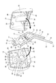
図7は、図5における下部クロスメンバ17の周辺部の拡大図である。
図3、図5及び図7を参照し、下部クロスメンバ17は、ヘッドレストステー15,15を左右に繋ぐ棒状に形成されている。下部クロスメンバ17は、板材を略L字状に折り曲げるようにして形成されており、その長手方向に垂直な断面視において、略水平に伸びる横板部85と、横板部85の一端から上方に延びる縦板部86とを備える。
縦板部86は、鉛直方向に対して横板部85の他端側に傾斜しており、横板部85と縦板部86とが成す角は90°よりも小さい。
Next, a configuration for efficiently cooling the control board 53 will be described.
FIG. 7 is an enlarged view of the periphery of the lower cross member 17 in FIG.
Referring to FIGS. 3, 5, and 7, the lower cross member 17 is formed in a rod shape that connects the headrest stays 15, 15 to the left and right. The lower cross member 17 is formed by bending a plate material into a substantially L shape, and in a cross-sectional view perpendicular to the longitudinal direction, the lower cross member 17 extends substantially horizontally and from above one end of the horizontal plate portion 85. And a vertical plate portion 86 extending in the vertical direction.
The vertical plate portion 86 is inclined toward the other end side of the horizontal plate portion 85 with respect to the vertical direction, and the angle formed by the horizontal plate portion 85 and the vertical plate portion 86 is smaller than 90 °.

横板部85は、他端から上方に延びる固定板部87を長手方向の両端にそれぞれ有し、固定孔部22は固定板部87に形成される。また、横板部85は、横板部85を他端側から切り欠いた切り欠き部85aを固定板部87,87の間に有する。
縦板部86は、長手方向の両端に固定孔部20をそれぞれ備える。縦板部86は、ヘッドレスト装置10の前面側に面する外側面86aと、外側面86aの裏側の内側面86bとを備える。
下部クロスメンバ17は、横板部85の他端及び縦板部86の上端を介し、長手方向の両端部がヘッドレストステー15,15にそれぞれ溶接される。
The horizontal plate portion 85 has a fixed plate portion 87 extending upward from the other end at both ends in the longitudinal direction, and the fixed hole portion 22 is formed in the fixed plate portion 87. Further, the horizontal plate portion 85 has a cutout portion 85 a formed by cutting the horizontal plate portion 85 from the other end side between the fixed plate portions 87 and 87.
The vertical plate portion 86 includes the fixed hole portions 20 at both ends in the longitudinal direction. The vertical plate portion 86 includes an outer surface 86a facing the front surface side of the headrest device 10 and an inner surface 86b on the back side of the outer surface 86a.
The lower cross member 17 is welded to the headrest stays 15 and 15 at both ends in the longitudinal direction via the other end of the horizontal plate portion 85 and the upper end of the vertical plate portion 86.

制御基板53は、集積回路であるLSI53aと、LSI53aを支持する基板53bとを備える。制御基板53は、内側面86b上において固定孔部20,20の間に設けられる。
制御基板53は、下部クロスメンバ17の内側面86bとLSI53aとの間に設けられる熱伝導部材88を介して内側面86bに取り付けられる。熱伝導部材88としては、熱伝導率の高い材質で構成されるシート状のものや、放熱グリスを用いることができる。
The control board 53 includes an LSI 53a that is an integrated circuit and a board 53b that supports the LSI 53a. The control board 53 is provided between the fixed holes 20 and 20 on the inner side surface 86b.
The control board 53 is attached to the inner side surface 86b via a heat conducting member 88 provided between the inner side surface 86b of the lower cross member 17 and the LSI 53a. As the heat conduction member 88, a sheet-like member made of a material having high heat conductivity or heat radiation grease can be used.

制御基板53の熱は、熱伝導部材88を介して下部クロスメンバ17に伝達され、さらに、下部クロスメンバ17からヘッドレストステー15,15及び上部クロスメンバ16に伝達され、フレーム11の全体から空気中に放熱される。すなわち、金属製で放熱性が高いフレーム11を制御基板53の放熱部材として用いるため、専用の放熱板等を追加せずに簡単な構成で制御基板53の熱を効率良く放熱できる。特に、ヘッドレストステー15,15は、下部がエンクロージャー部40の外側に延びているため、効果的に放熱できる。また、専用の放熱板等を追加しないため、エンクロージャー部40の内部空間40aの容積を大きく確保でき、低音の再生能力が良い。
なお、本第1の実施の形態では、制御基板53はエンクロージャー部40の内側に設けられているが、エンクロージャー部40を備えない構成において制御基板53がクッション13の内側に設けられる場合、制御基板53がフレーム11に接触して設けられていれば、フレーム11を介した熱伝導によって制御基板53を効率良く放熱できる。
The heat of the control board 53 is transmitted to the lower cross member 17 through the heat conducting member 88, and further transmitted from the lower cross member 17 to the headrest stays 15 and 15 and the upper cross member 16, and from the entire frame 11 into the air. Heat is dissipated. That is, since the frame 11 made of metal and having high heat dissipation is used as the heat dissipation member of the control board 53, the heat of the control board 53 can be efficiently radiated with a simple configuration without adding a dedicated heat sink or the like. In particular, the headrest stays 15 and 15 can effectively dissipate heat because their lower portions extend outside the enclosure portion 40. Moreover, since a dedicated heat sink or the like is not added, a large volume of the internal space 40a of the enclosure part 40 can be ensured, and a low sound reproduction capability is good.
In the first embodiment, the control board 53 is provided inside the enclosure unit 40. However, when the control board 53 is provided inside the cushion 13 in a configuration without the enclosure unit 40, the control board 53 is provided. If 53 is provided in contact with the frame 11, the control board 53 can be efficiently radiated by heat conduction through the frame 11.

また、エンクロージャー部40の内部空間40aの空気A(図1)は、ヘッドレストステー15,15の中空部70を通って下部開口72から外側に排出される。このため、制御基板53の放熱により熱せられた空気を中空部70を介して外側に排出でき、簡単な構成で制御基板53の熱を効率良く放熱できる。
また、LSI53aに熱伝導部材88を接触させるため、LSI53aの熱を効率良く下部クロスメンバ17に伝達できる。
さらに、着座者が背もたれ部5にもたれ掛かることで、背もたれ部5のクッションが変形し、これにより発生した空気流の一部は、下部開口72から中空部70に流れ、内部空間40aに流入し、制御基板53を冷却する。このため、着座者の動きによって発生する空気流を利用して制御基板53を効率良く冷却できる。
Further, the air A (FIG. 1) in the internal space 40 a of the enclosure part 40 passes through the hollow part 70 of the headrest stays 15, 15 and is discharged from the lower opening 72 to the outside. For this reason, the air heated by the heat radiation of the control board 53 can be discharged to the outside through the hollow portion 70, and the heat of the control board 53 can be efficiently radiated with a simple configuration.
Further, since the heat conducting member 88 is brought into contact with the LSI 53a, the heat of the LSI 53a can be efficiently transmitted to the lower cross member 17.
Furthermore, when the seated person leans against the backrest part 5, the cushion of the backrest part 5 is deformed, and a part of the air flow generated thereby flows from the lower opening 72 to the hollow part 70 and flows into the internal space 40a. Then, the control board 53 is cooled. For this reason, the control board 53 can be efficiently cooled using the airflow generated by the movement of the seated person.

図8は、ヘッドレスト装置10の音のボリュームと制御基板53の温度との関係を示す図表である。図8では、制御基板53を熱伝導部材88を介して内側面86bに取り付けた場合の結果R1と、制御基板53をフレーム11に接触させずに内部空間40aに設けた場合の結果R2とが示されている。
図8に示すように、音のボリュームが大きくなるほど音響スピーカー50,50等が要する電流が大きくなるため、制御基板53の温度は、ボリュームの増加に伴い増加する。
本実施の形態では、制御基板53を下部クロスメンバ17に取り付けることで、制御基板53をフレーム11に接触させない場合に比して、ボリュームの大きさに係わらず略20℃だけ温度を低下させることができた。
また、ボリュームが大きくなるほど音響スピーカー50,50等の振動が大きくなり、中空部70を流れて排出される空気Aの流量も増加する。すなわち、本実施の形態では、音のボリュームが大きくなるのに従って、自然に空気Aの流量が増加し、制御基板53の熱を放熱する能力が増加する。このため、効率良く制御基板53の熱を放熱できる。
FIG. 8 is a chart showing the relationship between the sound volume of the headrest device 10 and the temperature of the control board 53. In FIG. 8, a result R1 when the control board 53 is attached to the inner side surface 86b via the heat conducting member 88 and a result R2 when the control board 53 is provided in the internal space 40a without contacting the frame 11 are shown. It is shown.
As shown in FIG. 8, as the sound volume increases, the current required by the acoustic speakers 50, 50, etc. increases, so the temperature of the control board 53 increases as the volume increases.
In the present embodiment, by attaching the control board 53 to the lower cross member 17, the temperature is lowered by about 20 ° C. regardless of the size of the volume as compared with the case where the control board 53 is not in contact with the frame 11. I was able to.
Further, as the volume increases, the vibration of the acoustic speakers 50, 50, etc. increases, and the flow rate of the air A discharged through the hollow portion 70 also increases. In other words, in the present embodiment, as the sound volume increases, the flow rate of the air A naturally increases and the ability to dissipate the heat of the control board 53 increases. For this reason, the heat of the control board 53 can be efficiently radiated.

以上説明したように、本発明を適用した第1の実施の形態によれば、ヘッドレスト装置10は、密閉構造のクッション芯材12と、クッション芯材12に配置される音響スピーカー50,50と、クッション芯材12を貫通する中空のヘッドレストステー15,15とを有し、ヘッドレストステー15,15は、中空部70を介してクッション芯材12の内部の空気を外側に流通させる。これにより、ヘッドレストステー15,15を、低音の再生能力を向上させるダクトとして用いることができ、簡単な構造で低音の再生能力を向上できる。   As described above, according to the first embodiment to which the present invention is applied, the headrest device 10 includes the cushion core material 12 having a sealed structure, the acoustic speakers 50 and 50 disposed on the cushion core material 12, The headrest stays 15 and 15 have hollow headrest stays 15 and 15 penetrating the cushion core material 12, and the headrest stays 15 and 15 distribute the air inside the cushion core material 12 to the outside via the hollow portion 70. As a result, the headrest stays 15 and 15 can be used as ducts for improving the bass reproduction capability, and the bass reproduction capability can be improved with a simple structure.

また、ヘッドレストステー15,15は、パイプ形状の上端及び下端に、空気の連通孔である上部開口71,71及び下部開口72,72を備えるため、要求特性に合わせて上部開口71,71及び下部開口72,72の位置を設定することで音響特性を簡単な構成で最適化できる。
また、音響スピーカー50,50は左右一対で設けられ、ヘッドレストステー15,15は、音響スピーカー50,50に近接する位置に左右一対で設けられる。このため、左右の音響スピーカー50,50の低音の再生能力をバランス良く向上できる。
さらに、下部開口72,72は、着座者の耳から離れた背もたれ部5内で開口するため、下部開口72,72から放出される空気流の音が着座者に聞こえてしまうことを抑制できる。このため雑音を低減して音質を向上できる。
Moreover, since the headrest stays 15 and 15 are provided with upper openings 71 and 71 and lower openings 72 and 72 that are air communication holes at the upper and lower ends of the pipe shape, the upper openings 71 and 71 and the lower openings are arranged in accordance with required characteristics. The acoustic characteristics can be optimized with a simple configuration by setting the positions of the openings 72 and 72.
The acoustic speakers 50 and 50 are provided as a pair of left and right, and the headrest stays 15 and 15 are provided as a pair of left and right at positions close to the acoustic speakers 50 and 50. For this reason, the low-pitched sound reproduction ability of the left and right acoustic speakers 50, 50 can be improved in a well-balanced manner.
Furthermore, since the lower openings 72 and 72 are opened in the backrest part 5 away from the seated person's ear, it is possible to suppress the sound of the airflow emitted from the lower openings 72 and 72 from being heard by the seated person. For this reason, noise can be reduced and sound quality can be improved.

また、本発明を適用した第1の実施の形態によれば、ヘッドレスト装置10は、ヘッドレスト装置10の内側に設けられる金属製のフレーム11を備え、フレーム11は、シート1の背もたれ部5に接続されるヘッドレストステー15,15を一体に備え、発熱体としての制御基板53がフレーム11に固定される。このため、制御基板53の熱をヘッドレストステー15,15を含む金属製のフレーム11を介して外側に効率良く放熱できる。   Further, according to the first embodiment to which the present invention is applied, the headrest device 10 includes the metal frame 11 provided inside the headrest device 10, and the frame 11 is connected to the backrest portion 5 of the seat 1. The headrest stays 15 and 15 are integrally provided, and a control board 53 as a heating element is fixed to the frame 11. For this reason, the heat of the control board 53 can be efficiently radiated to the outside through the metal frame 11 including the headrest stays 15 and 15.

また、ヘッドレストステー15,15は、中空に構成されており、中空部70,70を介してヘッドレスト装置10の内部の空気を外側に流通させるため、中空部70,70から外側に流れる空気Aによって制御基板53の熱を外側に効率良く放熱できる。
さらに、フレーム11は、密閉構造のクッション芯材12の内側に設けられてクッション芯材12を支持し、ヘッドレストステー15,15は、クッション芯材12の内側の内部空間40aを外側に連通させる。このため、密閉構造のクッション芯材12の内側の内部空間40aの空気を中空部70,70から外側に流通させることができ、制御基板53の熱を外側に効率良く放熱できる。
Further, the headrest stays 15 and 15 are configured to be hollow, and the air inside the headrest device 10 is circulated to the outside via the hollow portions 70 and 70, so that the air A flowing from the hollow portions 70 and 70 to the outside is used. The heat of the control board 53 can be efficiently radiated to the outside.
Furthermore, the frame 11 is provided inside the cushion core material 12 having a sealed structure and supports the cushion core material 12, and the headrest stays 15 and 15 communicate the inner space 40 a inside the cushion core material 12 to the outside. For this reason, the air in the inner space 40a inside the cushion core member 12 having the sealed structure can be circulated from the hollow portions 70 and 70 to the outside, and the heat of the control board 53 can be efficiently radiated to the outside.

また、クッション芯材12には、音響スピーカー50,50が設けられるため、ヘッドレスト装置10から音を出力できるとともに、音響スピーカー50,50の出力による空気の流れによって、中空部70,70の空気Aの流通を促進できる。このため、制御基板53の熱を外側に効率良く放熱できる。
また、制御基板53は、音響スピーカー50,50の音響信号処理回路であるため、中空部70,70から外側に流れる空気Aによって、音響信号処理回路の発熱を効率良く放熱できる。
また、ヘッドレストステー15,15は、クッション芯材12の内部空間40aを背もたれ部5の内部に連通させるため、背もたれ部5の変形等による背もたれ部5内の空気の流動によって中空部70,70の空気の流通を促進できる。このため、制御基板53の熱を外側に効率良く放熱できる。
In addition, since the acoustic speaker 50, 50 is provided on the cushion core member 12, sound can be output from the headrest device 10, and air A of the hollow portions 70, 70 can be generated by the air flow generated by the output of the acoustic speaker 50, 50. Can be promoted. For this reason, the heat of the control board 53 can be efficiently radiated to the outside.
Further, since the control board 53 is an acoustic signal processing circuit for the acoustic speakers 50, 50, the heat A of the acoustic signal processing circuit can be efficiently radiated by the air A flowing from the hollow portions 70, 70 to the outside.
Further, the headrest stays 15, 15 communicate the inner space 40 a of the cushion core member 12 with the interior of the backrest 5, so that the hollow portions 70, 70 are formed by the flow of air in the backrest 5 due to deformation of the backrest 5. Air circulation can be promoted. For this reason, the heat of the control board 53 can be efficiently radiated to the outside.

[第2の実施の形態]
以下、図9及び図10を参照して、本発明を適用した第2の実施の形態について説明する。この第2の実施の形態において、上記第1の実施の形態と同様に構成される部分については、同符号を付して説明を省略する。
上記第1の実施の形態では、制御基板53は下部クロスメンバ17に設けられるものとして説明したが、本第2の実施の形態は、制御基板53が下部クロスメンバ17を有しないフレーム311に設けられる点が上記第1の実施の形態と異なる。
[Second Embodiment]
Hereinafter, a second embodiment to which the present invention is applied will be described with reference to FIGS. 9 and 10. In the second embodiment, parts that are configured in the same manner as in the first embodiment are given the same reference numerals, and descriptions thereof are omitted.
In the first embodiment, the control board 53 is described as being provided on the lower cross member 17. However, in the second embodiment, the control board 53 is provided on the frame 311 having no lower cross member 17. This is different from the first embodiment.

図9は、第2の実施の形態におけるフレーム311の上部を示す正面図である。
フレーム311(フレーム部材)の上部は、クッション芯材12の内側に位置し、クッション芯材12はフレーム311に支持される。
フレーム311は、金属製の中空の丸パイプを略U字状に曲げて形成されており、略鉛直に延びる一対のヘッドレストステー部315,315(ヘッドレストステー)と、ヘッドレストステー部315,315を繋ぐ略半円の円弧状の屈曲部316とを備える。フレーム311は、その全長に亘る中空部370を備える。
ヘッドレストステー部315,315は、中空部370を外側に連通させる不図示の下部開口(連通孔)を下端部に備える。また、ヘッドレストステー部315,315は、中空部370を外側に連通させる上部開口371(連通孔)を上端部に備える。上部開口371は、内部空間40aに開口する。
FIG. 9 is a front view showing the upper part of the frame 311 in the second embodiment.
The upper part of the frame 311 (frame member) is located inside the cushion core material 12, and the cushion core material 12 is supported by the frame 311.
The frame 311 is formed by bending a hollow metal pipe into a substantially U shape, and connects the pair of headrest stay portions 315 and 315 (headrest stay) extending substantially vertically and the headrest stay portions 315 and 315. And a substantially semicircular arc-shaped bent portion 316. The frame 311 includes a hollow portion 370 extending over the entire length thereof.
The headrest stay portions 315 and 315 include a lower opening (communication hole) (not shown) that allows the hollow portion 370 to communicate with the outside at the lower end portion. Moreover, the headrest stay parts 315 and 315 are provided with an upper opening 371 (communication hole) that allows the hollow part 370 to communicate with the outside. The upper opening 371 opens into the internal space 40a.

ヘッドレストステー部315,315は、周囲のヘッドレストステー部315,315よりも外径が小径に形成された小径部317,317を途中に有する。小径部317,317の中空部317a,317aの内径は、周囲のヘッドレストステー部315,315の中空部370の内径よりも小さい。すなわち、中空部317a,317aの断面積は、その周囲の中空部370の断面積よりも小さい。このため、中空部317a,317aを流れる空気の流速は、その周囲の中空部370を流れる空気の流速よりも大きい。
制御基板53は、左右のヘッドレストステー部315,315に跨って設けられる。詳細には、制御基板53は、長手方向の両端部が小径部317,317に取り付けられる。
The headrest stay portions 315 and 315 have small-diameter portions 317 and 317 having outer diameters smaller than those of the surrounding headrest stay portions 315 and 315. The inner diameters of the hollow portions 317a and 317a of the small diameter portions 317 and 317 are smaller than the inner diameter of the hollow portion 370 of the surrounding headrest stay portions 315 and 315. That is, the cross-sectional area of the hollow portions 317a and 317a is smaller than the cross-sectional area of the surrounding hollow portion 370. For this reason, the flow velocity of the air flowing through the hollow portions 317a and 317a is larger than the flow velocity of the air flowing through the surrounding hollow portion 370.
The control board 53 is provided across the left and right headrest stay portions 315 and 315. Specifically, the control board 53 is attached to the small diameter portions 317 and 317 at both ends in the longitudinal direction.

図10は、図のZ矢視図である。
制御基板53は、小径部317,317の外周面とLSI53aとの間に設けられる熱伝導部材88を介して小径部317,317に取り付けられる。
本第2の実施の形態では、ヘッドレストステー部315,315において制御基板53の近傍の部分である小径部317,317は、中空部317a,317aの断面積が周囲よりも小さく形成されているため、制御基板53の近傍の中空部317a,317aを流れる空気の流速を大きくできる。このため、制御基板53の熱を外側に効率良く放熱できる。
また、内側に凹んだ小径部317,317に制御基板53が配置されるため、制御基板53をコンパクトに配置できる。
さらに、ヘッドレストステー部315,315をバスレフダクトとして使用するため、低音を増強できる。
Figure 10 is a Z arrow view of FIG.
The control board 53 is attached to the small diameter portions 317 and 317 via a heat conducting member 88 provided between the outer peripheral surfaces of the small diameter portions 317 and 317 and the LSI 53a.
In the second embodiment, in the headrest stay portions 315 and 315, the small-diameter portions 317 and 317, which are portions in the vicinity of the control board 53, are formed so that the cross-sectional areas of the hollow portions 317a and 317a are smaller than the surroundings. The flow velocity of the air flowing through the hollow portions 317a and 317a in the vicinity of the control board 53 can be increased. For this reason, the heat of the control board 53 can be efficiently radiated to the outside.
Moreover, since the control board 53 is arrange | positioned in the small diameter parts 317 and 317 dented inside, the control board 53 can be arrange | positioned compactly.
Furthermore, since the headrest stay portions 315 and 315 are used as bass reflex ducts, bass can be enhanced.

なお、ヘッドレストステー部315,315に小径部317,317を設けずに、ヘッドレストステー部315,315を全長に亘って略同一径としても良い。この場合、制御基板53は、ヘッドレストステー部315,315の外周部に熱伝導部材88を介して取り付けられる。
また、上記第1の実施の形態のヘッドレストステー15,15の途中に、周囲のヘッドレストステー15,15の外径よりも小さい小径部を設け、この小径部の中空部の断面積を小さくしても良い。この場合、小径部を制御基板53の両端部の近傍に設けることで、制御基板53の近傍の中空部の流速を大きくでき、放熱の効率を向上できる。
また、上記第2の実施の形態では、ヘッドレストステー部315,315は、周囲のヘッドレストステー部315,315よりも外径が小径に形成された小径部317,317を途中に有するものとして説明したが、本発明はこれに限定されるものではない。例えば、小径部317,317に替えて、ヘッドレストステー部315,315の途中をプレス加工等により凹まして平面状の部分を設け、この平面状の部分に制御基板53を配置しても良い。すなわち、上記平面状の部分は、断面視でかまぼこ形状であり、このかまぼこ形状の平板状の部分に制御基板53を取り付けることで、ヘッドレストステー部315,315と制御基板53との接触面積を大きくすることができ、制御基板53の熱を効率良くヘッドレストステー部315,315に伝達することができる。
Note that the headrest stay portions 315 and 315 may have substantially the same diameter over the entire length without providing the headrest stay portions 315 and 315 with the small diameter portions 317 and 317. In this case, the control board 53 is attached to the outer peripheral portions of the headrest stay portions 315 and 315 via the heat conducting member 88.
Further, a small-diameter portion smaller than the outer diameter of the surrounding headrest stays 15 and 15 is provided in the middle of the headrest stays 15 and 15 of the first embodiment, and the cross-sectional area of the hollow portion of the small-diameter portion is reduced. Also good. In this case, by providing the small diameter portion in the vicinity of both end portions of the control board 53, the flow velocity of the hollow portion in the vicinity of the control board 53 can be increased, and the heat dissipation efficiency can be improved.
In the second embodiment, the headrest stay portions 315 and 315 have been described as having small-diameter portions 317 and 317 that have outer diameters smaller than those of the surrounding headrest stay portions 315 and 315. However, the present invention is not limited to this. For example, instead of the small-diameter portions 317 and 317, the headrest stay portions 315 and 315 may be recessed by pressing or the like to provide a planar portion, and the control board 53 may be disposed on the planar portion. In other words, the planar portion has a semi-cylindrical shape in a cross-sectional view, and the contact area between the headrest stay portions 315 and 315 and the control substrate 53 is increased by attaching the control substrate 53 to the semi-cylindrical flat plate-like portion. The heat of the control board 53 can be efficiently transmitted to the headrest stay portions 315 and 315.

[第3の実施の形態]
以下、図11を参照して、本発明を適用した第3の実施の形態について説明する。この第3の実施の形態において、上記第1の実施の形態と同様に構成される部分については、同符号を付して説明を省略する。
第3の実施の形態は、上記第1の実施の形態とは異なる位置に空気の連通孔が設けられている。
[Third Embodiment]
A third embodiment to which the present invention is applied will be described below with reference to FIG. In the third embodiment, parts that are configured in the same manner as in the first embodiment are given the same reference numerals, and descriptions thereof are omitted.
In the third embodiment, air communication holes are provided at positions different from those of the first embodiment.

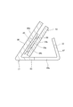
図11は、第3の実施の形態におけるフレーム111の構成を示す図である。
ヘッドレスト装置110は、フレーム11に替えてフレーム111を備える。
フレーム111は、背もたれ部5の上面に形成された取り付け孔部(不図示)に挿入されるヘッドレストステー115,115と、エンクロージャー部40(図4)の内側でヘッドレストステー115,115の上端部を左右に連結するクロスメンバ117とを備える。
FIG. 11 is a diagram illustrating a configuration of the frame 111 according to the third embodiment.
The headrest device 110 includes a frame 111 instead of the frame 11.
The frame 111 includes headrest stays 115 and 115 that are inserted into attachment holes (not shown) formed on the upper surface of the backrest portion 5, and upper end portions of the headrest stays 115 and 115 inside the enclosure portion 40 (FIG. 4). And a cross member 117 connected to the left and right.

各ヘッドレストステー115,115は、中空のパイプ状のステー本体175と、ステー本体175の上端に連結される中空の延長パイプ部176と、ステー本体175の下端を塞ぐ蓋部材177とを備える。ステー本体175及びクロスメンバ117は金属製である。延長パイプ部176及び蓋部材177はステー本体175の材質よりも軽量な樹脂製である。
クロスメンバ117は、延長パイプ部176に設けられる。ステー本体175と延長パイプ部176とは繋げられて一体化され、その全長に亘る中空部170を備える。延長パイプ部176は、エンクロージャー部40内で開口する上部開口171(連通孔)を上端に備える。すなわち、ステー本体175に延長パイプ部176を追加することで、各ヘッドレストステー115,115の開口位置が上方に移動している。また、延長パイプ部176は樹脂性で軽量であるため、重量を大きく増加させずに、上部開口171の位置を調整できる。
Each headrest stay 115, 115 includes a hollow pipe-like stay main body 175, a hollow extension pipe portion 176 connected to the upper end of the stay main body 175, and a lid member 177 that closes the lower end of the stay main body 175. The stay main body 175 and the cross member 117 are made of metal. The extension pipe portion 176 and the lid member 177 are made of resin that is lighter than the material of the stay body 175.
The cross member 117 is provided on the extension pipe portion 176. The stay main body 175 and the extension pipe portion 176 are connected and integrated, and have a hollow portion 170 extending over the entire length thereof. The extension pipe part 176 includes an upper opening 171 (communication hole) that opens in the enclosure part 40 at the upper end. That is, by adding the extension pipe portion 176 to the stay main body 175, the opening positions of the headrest stays 115 and 115 are moved upward. Moreover, since the extension pipe part 176 is resinous and lightweight, the position of the upper opening 171 can be adjusted without greatly increasing the weight.

ステー本体175の下端の開口175aは、蓋部材177によって塞がれる。ステー本体175は、開口175aよりも上方の側面に、中空部170に連通する側面開口172(連通孔)を備える。側面開口172は、背もたれ部5の内部に開口する。すなわち、ステー本体175の下端の開口175aを蓋部材177で塞ぐとともにその上方に側面開口172を設けることで、中空部170の下端側の開口の位置が上方に移動している。蓋部材177は樹脂性で軽量であるため、各ヘッドレストステー115,115の重量を大きく増加させることがない。
このように、延長パイプ部176及び蓋部材177をステー本体175に追加することで、音響特性の優れた任意の位置に上部開口171及び側面開口172を設けることができる。なお、延長パイプ部176及び蓋部材177は同時に用いられる必要はなく、必要な音響特性に応じて単独で用いられることができる。
また、第3の実施の形態では、連通孔として上部開口171及び側面開口172を例に挙げて説明したが、これに限らず、連通孔は、エンクロージャー部40の内側とエンクロージャー部40の外側とに少なくとも一対設けられていれば良く、連通孔の位置は、音響特性や配置スペースの制約等によって任意の位置に設定される。すなわち、連通孔は、ヘッドレストステー115,115の側面に一対設けられても良く、或いは、ヘッドレストステー115,115の端と側面とに設けられても良い。
An opening 175 a at the lower end of the stay main body 175 is closed by a lid member 177. The stay main body 175 includes a side surface opening 172 (communication hole) communicating with the hollow portion 170 on the side surface above the opening 175a. The side opening 172 opens inside the backrest 5. That is, the opening 175a at the lower end of the stay main body 175 is closed with the lid member 177 and the side opening 172 is provided above the opening 175a, whereby the position of the opening on the lower end side of the hollow portion 170 is moved upward. Since the lid member 177 is resinous and lightweight, the weights of the headrest stays 115 and 115 are not greatly increased.
As described above, by adding the extension pipe portion 176 and the lid member 177 to the stay main body 175, the upper opening 171 and the side opening 172 can be provided at arbitrary positions having excellent acoustic characteristics. In addition, the extension pipe part 176 and the cover member 177 do not need to be used simultaneously, but can be used independently according to a required acoustic characteristic.
In the third embodiment, the upper opening 171 and the side opening 172 are described as examples of the communication holes. However, the communication holes are not limited to this, and the communication holes are formed on the inside of the enclosure part 40 and the outside of the enclosure part 40. It is sufficient that at least one pair is provided, and the position of the communication hole is set at an arbitrary position depending on the acoustic characteristics, the restriction of the arrangement space, and the like. That is, a pair of communication holes may be provided on the side surfaces of the headrest stays 115 and 115, or may be provided on the ends and side surfaces of the headrest stays 115 and 115.

[第4の実施の形態]
以下、図12及び図13を参照して、本発明を適用した第4の実施の形態について説明する。この第4の実施の形態において、上記第1の実施の形態と同様に構成される部分については、同符号を付して説明を省略する。
第4の実施の形態は、ヘッドレストステー15,15の下部開口72に連通する拡張エンクロージャー281が背もたれ部5に設けられる点が、上記第1の実施の形態と異なる。
[Fourth Embodiment]
Hereinafter, a fourth embodiment to which the present invention is applied will be described with reference to FIGS. 12 and 13. In the fourth embodiment, parts that are configured in the same manner as in the first embodiment are given the same reference numerals, and descriptions thereof are omitted.
The fourth embodiment is different from the first embodiment in that an expansion enclosure 281 communicating with the lower opening 72 of the headrest stays 15 and 15 is provided in the backrest portion 5.

図12は、第4の実施の形態に係るシート201の構造を示す模式図である。図13は、シート201の内部構成を示す図である。
音響装置としてのシート201(音響装置)は、座面部3と、背もたれ部5と、ヘッドレスト装置10とを備える。
背もたれ部5は、シートフレーム(不図示)と、シートフレームの周囲に設けられるクッション(不図示)と、このクッションを覆うカバー部材280とを備える。
カバー部材280は、背もたれ部5の前面の略全体に設けられて着座者の背中に接触する背もたれ前面部280aと、背もたれ後面部280bとを備える。
背もたれ前面部280aは、通気性の良い、例えば樹脂や布等の素材により構成される。背もたれ後面部280bは、背もたれ前面部280aよりも通気性が低い(背もたれ前面部280aよりも通音性が低い)、例えば木材、コルク及び樹脂等の素材により構成される。
FIG. 12 is a schematic diagram illustrating a structure of a sheet 201 according to the fourth embodiment. FIG. 13 is a diagram illustrating an internal configuration of the sheet 201.
A seat 201 (acoustic device) as an acoustic device includes a seat surface portion 3, a backrest portion 5, and a headrest device 10.
The backrest 5 includes a seat frame (not shown), a cushion (not shown) provided around the seat frame, and a cover member 280 that covers the cushion.
The cover member 280 includes a backrest front surface portion 280a that is provided on substantially the entire front surface of the backrest portion 5 and contacts the back of the seated person, and a backrest rear surface portion 280b.
The backrest front portion 280a is made of a material having good air permeability, such as resin or cloth. The backrest rear surface portion 280b has a lower air permeability than the backrest front surface portion 280a (has a lower sound permeability than the backrest front surface portion 280a), and is made of a material such as wood, cork, or resin.

背もたれ部5の内部には、箱状の拡張エンクロージャー281が設けられている。拡張エンクロージャー281は、前記クッションの内部に埋め込まれるようにして配置される。拡張エンクロージャー281は、着座者側へ内部の空気を放出させるポート282を、背もたれ前面部280aに面する前面に備える。
ヘッドレスト装置10のヘッドレストステー15,15は、拡張エンクロージャー281に接続される。詳細には、ヘッドレストステー15,15は、拡張エンクロージャー281の上面281aを貫通して拡張エンクロージャー281の内部空間に侵入し、ヘッドレストステー15,15の下部開口72は、拡張エンクロージャー281の内部空間に開口する。
A box-shaped expansion enclosure 281 is provided inside the backrest 5. The expansion enclosure 281 is disposed so as to be embedded in the cushion. The expansion enclosure 281 is provided with a port 282 that discharges internal air to the seated person, on the front surface facing the backrest front surface portion 280a.
The headrest stays 15, 15 of the headrest device 10 are connected to the expansion enclosure 281. Specifically, the headrest stays 15, 15 penetrate the upper surface 281 a of the expansion enclosure 281 and enter the internal space of the expansion enclosure 281, and the lower opening 72 of the headrest stays 15, 15 opens into the internal space of the expansion enclosure 281. To do.

すなわち、エンクロージャー部40の内部空間40aと拡張エンクロージャー281の内部空間とは、ヘッドレストステー15,15の中空部70を介して連通している。
音響スピーカー50,50及びサブウーハー52の駆動によりエンクロージャー部40から放出された空気は、中空部70を通って拡張エンクロージャー281内に流れ、ポート282から前方の着座者側に放出される。
このため、拡張エンクロージャー281によって音響装置のエンクロージャーの容積を拡大して低音を増強できるとともに、音響スピーカー50,50の駆動に連動する空気流を着座者に直接的に当てることができ、着座者に音を感じ易くさせることができる。なお、拡張エンクロージャー281を設けるだけでエンクロージャーの容積を拡大して低音を増強できるため、ポート282を設けない構成としても良い。
さらに、背もたれ前面部280aは、背もたれ後面部280bよりも通音声が高く構成されている。このため、拡張エンクロージャー281の放出する音を背もたれ前面部280a側に指向させて出力でき、着座者側に良好な低音を感じさせることができる。
That is, the internal space 40 a of the enclosure part 40 and the internal space of the expansion enclosure 281 are communicated via the hollow part 70 of the headrest stays 15 and 15.
The air emitted from the enclosure part 40 by the driving of the acoustic speakers 50 and 50 and the subwoofer 52 flows into the expansion enclosure 281 through the hollow part 70 and is emitted from the port 282 to the front seated person side.
For this reason, the volume of the enclosure of the audio device can be increased by the expansion enclosure 281 to enhance the bass, and the air flow linked to the driving of the acoustic speakers 50 and 50 can be directly applied to the occupant. The sound can be easily felt. In addition, since the volume of the enclosure can be expanded and the bass can be enhanced only by providing the expansion enclosure 281, the port 282 may be omitted.
Further, the backrest front portion 280a is configured to have higher voice volume than the backrest rear portion 280b. For this reason, the sound emitted from the expansion enclosure 281 can be directed and output to the backrest front surface portion 280a side, and a good bass can be felt on the seated person side.

なお、上記第1〜第4の実施の形態は本発明を適用した一態様を示すものであって、本発明は上記第1〜第4の実施の形態に限定されるものではない。
上記第1〜第4の実施の形態では、発熱体としての制御基板53は、音信号処理回路や、音響マイク51を制御するための制御回路などが搭載されているものであるとして説明したが、本発明はこれに限定されるものではない。発熱体は電子機器に関するものであれば良く、例えば、電動シートの動作を制御する制御基板や、ヘッドレスト装置10に内蔵されたセンサー基板等であっても良い。
また、上記第4の実施の形態では、背もたれ部5の内部には、箱状の拡張エンクロージャー281が設けられるものとして説明したが、本発明はこれに限定されるものではない。例えば、拡張エンクロージャー281を設けずに、背もたれ前面部280aを孔空きの表皮や通気性の良い素材で形成して通気性が高い構成とし、背もたれ後面部280b及び背もたれ部5の左右の側面の略全体をゴム系等の通気性の低い素材で覆う構成としても良い。この場合、背もたれ部5から放出される音を背もたれ前面部280a側に指向させて出力でき、拡張エンクロージャー281を設けた場合と同様の効果を得られる。
In addition, the said 1st-4th embodiment shows the one aspect | mode which applied this invention, Comprising: This invention is not limited to the said 1st-4th embodiment.
In the above first to fourth embodiments, the control board 53 as a heat generating body, and acoustic signal processing circuit, a control circuit for controlling the acoustic microphone 51 has been described as being mounted However, the present invention is not limited to this. The heating element may be any electronic device, and may be, for example, a control board for controlling the operation of the electric seat, a sensor board built in the headrest device 10, or the like.
In the fourth embodiment described above, the box-shaped expansion enclosure 281 is provided inside the backrest 5, but the present invention is not limited to this. For example, without providing the expansion enclosure 281, the back surface front portion 280 a is formed of a perforated skin or a material having good air permeability so as to have a high air permeability. It is good also as a structure which covers the whole with materials with low air permeability, such as a rubber type. In this case, the sound emitted from the backrest portion 5 can be output by directing it toward the backrest front portion 280a, and the same effect as when the expansion enclosure 281 is provided can be obtained.

1 シート
5 背もたれ部
10,110 ヘッドレスト装置(音響装置)
12 クッション芯材(芯材、ヘッドレスト本体)
15,15,115,115 ヘッドレストステー
50,50 音響スピーカー
70,70,170,170,370 中空部
71,171 上部開口(連通孔)
72 下部開口(連通孔)
172 側面開口(連通孔)
201 シート(音響装置)
281 拡張エンクロージャー
282 ポート
315,315 ヘッドレストステー部(ヘッドレストステー)
371 上部開口(連通孔)
1 seat 5 backrest part 10,110 headrest device (acoustic device)
12 Cushion core (core, headrest body)
15, 15, 115, 115 Headrest stay 50, 50 Acoustic speaker 70, 70, 170, 170, 370 Hollow part 71, 171 Upper opening (communication hole)
72 Lower opening (communication hole)
172 Side opening (communication hole)
201 sheet (acoustic device)
281 Expansion enclosure 282 Ports 315, 315 Headrest stay (headrest stay)
371 Upper opening (communication hole)

Claims (5)

ヘッドレスト本体の芯となる密閉構造の芯材と、当該芯材に配置される音響スピーカーと、前記芯材を貫通する中空のヘッドレストステーとを有し、前記ヘッドレスト本体は前記ヘッドレストステーがシートの背もたれ部に挿入されて前記背もたれ部に接続され、
前記ヘッドレストステーは、中空部を介して前記芯材の内部空間と前記背もたれ部の内部とを連通させ
前記ヘッドレストステーは、空気の連通孔を備え、前記連通孔の内、前記芯材の内部空間で開口する前記連通孔は、前記音響スピーカーの後方に位置するとともに、前記ヘッドレストステーの上方に開口することを特徴とする音響装置。
The headrest body includes a core material having a sealed structure, a sound speaker disposed on the core material, and a hollow headrest stay that penetrates the core material, and the headrest body includes a backrest of a seat. Inserted into the part and connected to the backrest part,
The headrest stay communicates the internal space of the core member and the interior of the backrest part through a hollow part ,
The headrest stay includes an air communication hole, and the communication hole that opens in the internal space of the core member is located behind the acoustic speaker and opens above the headrest stay. An acoustic device characterized by that.
前記連通孔の内、前記背もたれ部内で開口する前記連通孔は、前記ヘッドレストステーのパイプ形状の端または側面に設けられ、
前記パイプ形状の前記側面に前記連通孔が設けられる場合、前記背もたれ部内の前記パイプ形状の前記端は塞がれ、前記側面の前記連通孔を空気が流通し、
前記パイプ形状の前記側面に前記連通孔が設けられない場合、前記背もたれ部内の前記パイプ形状の前記端は塞がれず、前記端を空気が流通することを特徴とする請求項1記載の音響装置。
Of the communication holes, the communication hole that opens in the backrest portion is provided on a pipe-shaped end or side surface of the headrest stay ,
When the communication hole is provided on the side surface of the pipe shape, the end of the pipe shape in the backrest portion is closed, and air flows through the communication hole of the side surface,
2. The acoustic device according to claim 1 , wherein when the communication hole is not provided in the side surface of the pipe shape, the end of the pipe shape in the backrest portion is not blocked and air flows through the end. .
前記背もたれ部の内部に設けられる拡張エンクロージャーを備え、前記ヘッドレストステーは、前記拡張エンクロージャーに連通することを特徴とする請求項1または2記載の音響装置。   The acoustic device according to claim 1, further comprising an expansion enclosure provided inside the backrest, wherein the headrest stay communicates with the expansion enclosure. 前記拡張エンクロージャーは、前記背もたれ部の前面側へ空気を放出させるポートを備えることを特徴とする請求項3記載の音響装置。   The acoustic device according to claim 3, wherein the expansion enclosure includes a port that discharges air to a front side of the backrest portion. 前記音響スピーカーは左右一対で設けられ、前記ヘッドレストステーは、前記音響スピーカーに近接する位置に左右一対で設けられることを特徴とする請求項1から4のいずれかに記載の音響装置。   5. The acoustic device according to claim 1, wherein the acoustic speakers are provided in a pair of left and right, and the headrest stay is provided in a pair of left and right at a position close to the acoustic speaker.
JP2014132670A 2014-06-27 2014-06-27 Sound equipment Active JP6446189B2 (en)

Priority Applications (5)

Application Number Priority Date Filing Date Title
JP2014132670A JP6446189B2 (en) 2014-06-27 2014-06-27 Sound equipment
PCT/JP2015/064052 WO2015198745A1 (en) 2014-06-27 2015-05-15 Acoustic device
US15/307,889 US10328831B2 (en) 2014-06-27 2015-05-15 Acoustic device
EP15812128.5A EP3162622B1 (en) 2014-06-27 2015-05-15 Acoustic device
CN201580030026.3A CN106414167B (en) 2014-06-27 2015-05-15 Audio device

Applications Claiming Priority (1)

Application Number Priority Date Filing Date Title
JP2014132670A JP6446189B2 (en) 2014-06-27 2014-06-27 Sound equipment

Publications (3)

Publication Number Publication Date
JP2016011005A JP2016011005A (en) 2016-01-21
JP2016011005A5 JP2016011005A5 (en) 2017-06-22
JP6446189B2 true JP6446189B2 (en) 2018-12-26

Family

ID=55228012

Family Applications (1)

Application Number Title Priority Date Filing Date
JP2014132670A Active JP6446189B2 (en) 2014-06-27 2014-06-27 Sound equipment

Country Status (1)

Country Link
JP (1) JP6446189B2 (en)

Families Citing this family (3)

* Cited by examiner, † Cited by third party
Publication number Priority date Publication date Assignee Title
US10696201B2 (en) 2016-05-25 2020-06-30 Clarion Co., Ltd. Headrest and vehicle seat
WO2019175967A1 (en) * 2018-03-13 2019-09-19 株式会社ソシオネクスト Steering device and speech output system
FR3097487B1 (en) * 2019-06-18 2022-11-04 Faurecia Sieges Dautomobile Headrest for vehicle seat, with built-in loudspeaker

Family Cites Families (7)

* Cited by examiner, † Cited by third party
Publication number Priority date Publication date Assignee Title
JPS6128468Y2 (en) * 1981-05-22 1986-08-23
KR940005196B1 (en) * 1991-07-03 1994-06-13 삼성전관 주식회사 Fluorescent substance based on zinc sulphide
KR960001089Y1 (en) * 1993-01-12 1996-02-07 조철수 Frame of multi-functional headrest for a car-seat
JPH07264689A (en) * 1994-03-16 1995-10-13 Fujitsu Ten Ltd Headrest speaker
US6669285B1 (en) * 2002-07-02 2003-12-30 Eric Park Headrest mounted video display
JP4802824B2 (en) * 2006-04-04 2011-10-26 トヨタ自動車株式会社 Noise control structure
JP5118892B2 (en) * 2007-05-29 2013-01-16 株式会社イノアックコーポレーション Manufacturing method of headrest

Also Published As

Publication number Publication date
JP2016011005A (en) 2016-01-21

Similar Documents

Publication Publication Date Title
US10328831B2 (en) Acoustic device
JP6423906B2 (en) Sound collector
JP6396698B2 (en) Headrest device
JP3880865B2 (en) Chair with speaker
EP3094517B1 (en) Vehicle headrest
JP4180662B2 (en) Personnel vehicle having a loudspeaker with panel-shaped acoustic radiating elements
JP4264068B2 (en) Acoustic wave induction in vehicles
JP4263252B2 (en) Device with built-in electroacoustic transducer for optimal sound reproduction
JP2009260524A (en) Speaker system
JP6446189B2 (en) Sound equipment
US11345266B2 (en) Headrest with loudspeaker for vehicle seat
JP6247907B2 (en) Headrest device
US9967672B2 (en) Audio system
JP6374153B2 (en) Headrest device
JP2006273164A (en) On-vehicle acoustic system and on-vehicle seat
CN219467600U (en) Headrest and housing for a motor vehicle seat
JP2006020163A (en) Speaker unit mounting structure and vehicle seat
JP2022018899A (en) Cabin acoustic device
US20220286764A1 (en) Near to the ear subwoofer
JP2006254396A (en) Back reliance cushion for two-wheeled vehicle having acoustic system
JP2009260525A (en) Speaker system
JP2023056478A (en) vehicle seat
KR0174195B1 (en) Car speaker assembly
JPH0358699A (en) On-vehicle speaker equipment

Legal Events

Date Code Title Description
A521 Request for written amendment filed

Free format text: JAPANESE INTERMEDIATE CODE: A523

Effective date: 20170511

A621 Written request for application examination

Free format text: JAPANESE INTERMEDIATE CODE: A621

Effective date: 20170511

A131 Notification of reasons for refusal

Free format text: JAPANESE INTERMEDIATE CODE: A131

Effective date: 20180227

A521 Request for written amendment filed

Free format text: JAPANESE INTERMEDIATE CODE: A523

Effective date: 20180426

A131 Notification of reasons for refusal

Free format text: JAPANESE INTERMEDIATE CODE: A131

Effective date: 20180807

A521 Request for written amendment filed

Free format text: JAPANESE INTERMEDIATE CODE: A523

Effective date: 20181004

TRDD Decision of grant or rejection written
A01 Written decision to grant a patent or to grant a registration (utility model)

Free format text: JAPANESE INTERMEDIATE CODE: A01

Effective date: 20181113

A61 First payment of annual fees (during grant procedure)

Free format text: JAPANESE INTERMEDIATE CODE: A61

Effective date: 20181203

R150 Certificate of patent or registration of utility model

Ref document number: 6446189

Country of ref document: JP

Free format text: JAPANESE INTERMEDIATE CODE: R150

R250 Receipt of annual fees

Free format text: JAPANESE INTERMEDIATE CODE: R250

R250 Receipt of annual fees

Free format text: JAPANESE INTERMEDIATE CODE: R250

S531 Written request for registration of change of domicile

Free format text: JAPANESE INTERMEDIATE CODE: R313531

R350 Written notification of registration of transfer

Free format text: JAPANESE INTERMEDIATE CODE: R350

R250 Receipt of annual fees

Free format text: JAPANESE INTERMEDIATE CODE: R250