JP6446121B2 - Lighting device and display device - Google Patents
Lighting device and display device Download PDFInfo
- Publication number
- JP6446121B2 JP6446121B2 JP2017506537A JP2017506537A JP6446121B2 JP 6446121 B2 JP6446121 B2 JP 6446121B2 JP 2017506537 A JP2017506537 A JP 2017506537A JP 2017506537 A JP2017506537 A JP 2017506537A JP 6446121 B2 JP6446121 B2 JP 6446121B2
- Authority
- JP
- Japan
- Prior art keywords
- light source
- power supply
- bottom wall
- connector
- light
- Prior art date
- Legal status (The legal status is an assumption and is not a legal conclusion. Google has not performed a legal analysis and makes no representation as to the accuracy of the status listed.)
- Active
Links
Images


Classifications
-
- G—PHYSICS
- G02—OPTICS
- G02B—OPTICAL ELEMENTS, SYSTEMS OR APPARATUS
- G02B6/00—Light guides; Structural details of arrangements comprising light guides and other optical elements, e.g. couplings
- G02B6/0001—Light guides; Structural details of arrangements comprising light guides and other optical elements, e.g. couplings specially adapted for lighting devices or systems
- G02B6/0011—Light guides; Structural details of arrangements comprising light guides and other optical elements, e.g. couplings specially adapted for lighting devices or systems the light guides being planar or of plate-like form
- G02B6/0033—Means for improving the coupling-out of light from the light guide
- G02B6/005—Means for improving the coupling-out of light from the light guide provided by one optical element, or plurality thereof, placed on the light output side of the light guide
- G02B6/0055—Reflecting element, sheet or layer
-
- G—PHYSICS
- G02—OPTICS
- G02F—OPTICAL DEVICES OR ARRANGEMENTS FOR THE CONTROL OF LIGHT BY MODIFICATION OF THE OPTICAL PROPERTIES OF THE MEDIA OF THE ELEMENTS INVOLVED THEREIN; NON-LINEAR OPTICS; FREQUENCY-CHANGING OF LIGHT; OPTICAL LOGIC ELEMENTS; OPTICAL ANALOGUE/DIGITAL CONVERTERS
- G02F1/00—Devices or arrangements for the control of the intensity, colour, phase, polarisation or direction of light arriving from an independent light source, e.g. switching, gating or modulating; Non-linear optics
- G02F1/01—Devices or arrangements for the control of the intensity, colour, phase, polarisation or direction of light arriving from an independent light source, e.g. switching, gating or modulating; Non-linear optics for the control of the intensity, phase, polarisation or colour
- G02F1/13—Devices or arrangements for the control of the intensity, colour, phase, polarisation or direction of light arriving from an independent light source, e.g. switching, gating or modulating; Non-linear optics for the control of the intensity, phase, polarisation or colour based on liquid crystals, e.g. single liquid crystal display cells
- G02F1/133—Constructional arrangements; Operation of liquid crystal cells; Circuit arrangements
- G02F1/1333—Constructional arrangements; Manufacturing methods
- G02F1/1335—Structural association of cells with optical devices, e.g. polarisers or reflectors
- G02F1/1336—Illuminating devices
- G02F1/133602—Direct backlight
- G02F1/133603—Direct backlight with LEDs
-
- F—MECHANICAL ENGINEERING; LIGHTING; HEATING; WEAPONS; BLASTING
- F21—LIGHTING
- F21S—NON-PORTABLE LIGHTING DEVICES; SYSTEMS THEREOF; VEHICLE LIGHTING DEVICES SPECIALLY ADAPTED FOR VEHICLE EXTERIORS
- F21S2/00—Systems of lighting devices, not provided for in main groups F21S4/00 - F21S10/00 or F21S19/00, e.g. of modular construction
-
- F—MECHANICAL ENGINEERING; LIGHTING; HEATING; WEAPONS; BLASTING
- F21—LIGHTING
- F21V—FUNCTIONAL FEATURES OR DETAILS OF LIGHTING DEVICES OR SYSTEMS THEREOF; STRUCTURAL COMBINATIONS OF LIGHTING DEVICES WITH OTHER ARTICLES, NOT OTHERWISE PROVIDED FOR
- F21V23/00—Arrangement of electric circuit elements in or on lighting devices
- F21V23/06—Arrangement of electric circuit elements in or on lighting devices the elements being coupling devices, e.g. connectors
-
- G—PHYSICS
- G02—OPTICS
- G02F—OPTICAL DEVICES OR ARRANGEMENTS FOR THE CONTROL OF LIGHT BY MODIFICATION OF THE OPTICAL PROPERTIES OF THE MEDIA OF THE ELEMENTS INVOLVED THEREIN; NON-LINEAR OPTICS; FREQUENCY-CHANGING OF LIGHT; OPTICAL LOGIC ELEMENTS; OPTICAL ANALOGUE/DIGITAL CONVERTERS
- G02F1/00—Devices or arrangements for the control of the intensity, colour, phase, polarisation or direction of light arriving from an independent light source, e.g. switching, gating or modulating; Non-linear optics
- G02F1/01—Devices or arrangements for the control of the intensity, colour, phase, polarisation or direction of light arriving from an independent light source, e.g. switching, gating or modulating; Non-linear optics for the control of the intensity, phase, polarisation or colour
- G02F1/13—Devices or arrangements for the control of the intensity, colour, phase, polarisation or direction of light arriving from an independent light source, e.g. switching, gating or modulating; Non-linear optics for the control of the intensity, phase, polarisation or colour based on liquid crystals, e.g. single liquid crystal display cells
- G02F1/133—Constructional arrangements; Operation of liquid crystal cells; Circuit arrangements
- G02F1/1333—Constructional arrangements; Manufacturing methods
- G02F1/1335—Structural association of cells with optical devices, e.g. polarisers or reflectors
- G02F1/1336—Illuminating devices
- G02F1/133602—Direct backlight
- G02F1/133608—Direct backlight including particular frames or supporting means
-
- H—ELECTRICITY
- H05—ELECTRIC TECHNIQUES NOT OTHERWISE PROVIDED FOR
- H05K—PRINTED CIRCUITS; CASINGS OR CONSTRUCTIONAL DETAILS OF ELECTRIC APPARATUS; MANUFACTURE OF ASSEMBLAGES OF ELECTRICAL COMPONENTS
- H05K1/00—Printed circuits
- H05K1/02—Details
- H05K1/14—Structural association of two or more printed circuits
- H05K1/142—Arrangements of planar printed circuit boards in the same plane, e.g. auxiliary printed circuit insert mounted in a main printed circuit
-
- G—PHYSICS
- G02—OPTICS
- G02F—OPTICAL DEVICES OR ARRANGEMENTS FOR THE CONTROL OF LIGHT BY MODIFICATION OF THE OPTICAL PROPERTIES OF THE MEDIA OF THE ELEMENTS INVOLVED THEREIN; NON-LINEAR OPTICS; FREQUENCY-CHANGING OF LIGHT; OPTICAL LOGIC ELEMENTS; OPTICAL ANALOGUE/DIGITAL CONVERTERS
- G02F1/00—Devices or arrangements for the control of the intensity, colour, phase, polarisation or direction of light arriving from an independent light source, e.g. switching, gating or modulating; Non-linear optics
- G02F1/01—Devices or arrangements for the control of the intensity, colour, phase, polarisation or direction of light arriving from an independent light source, e.g. switching, gating or modulating; Non-linear optics for the control of the intensity, phase, polarisation or colour
- G02F1/13—Devices or arrangements for the control of the intensity, colour, phase, polarisation or direction of light arriving from an independent light source, e.g. switching, gating or modulating; Non-linear optics for the control of the intensity, phase, polarisation or colour based on liquid crystals, e.g. single liquid crystal display cells
- G02F1/133—Constructional arrangements; Operation of liquid crystal cells; Circuit arrangements
- G02F1/1333—Constructional arrangements; Manufacturing methods
- G02F1/1335—Structural association of cells with optical devices, e.g. polarisers or reflectors
- G02F1/1336—Illuminating devices
- G02F1/133602—Direct backlight
- G02F1/133612—Electrical details
-
- H—ELECTRICITY
- H05—ELECTRIC TECHNIQUES NOT OTHERWISE PROVIDED FOR
- H05K—PRINTED CIRCUITS; CASINGS OR CONSTRUCTIONAL DETAILS OF ELECTRIC APPARATUS; MANUFACTURE OF ASSEMBLAGES OF ELECTRICAL COMPONENTS
- H05K2201/00—Indexing scheme relating to printed circuits covered by H05K1/00
- H05K2201/10—Details of components or other objects attached to or integrated in a printed circuit board
- H05K2201/10007—Types of components
- H05K2201/10106—Light emitting diode [LED]
Description
本発明は、光源基板が複数枚並置された照明装置及び表示装置に関する。 The present invention relates to an illumination device and a display device in which a plurality of light source substrates are juxtaposed.
液晶表示装置は、液晶表示パネルと、複数個のLED(発光ダイオード)を有する照明装置とを備える。照明装置は、液晶表示パネルを背面側から照明する。
エッジライト型の照明装置の場合、LEDは、液晶表示パネルに対面配置された導光板の端面に対向して複数個並置される(特許文献1参照)。
直下型の照明装置の場合、LEDは、液晶表示パネルの背面に対向して複数個並置される(特許文献2〜4参照)。The liquid crystal display device includes a liquid crystal display panel and an illumination device having a plurality of LEDs (light emitting diodes). The illumination device illuminates the liquid crystal display panel from the back side.
In the case of an edge light type lighting device, a plurality of LEDs are juxtaposed facing the end face of a light guide plate disposed facing the liquid crystal display panel (see Patent Document 1).
In the case of a direct illumination device, a plurality of LEDs are juxtaposed facing the back surface of the liquid crystal display panel (see Patent Documents 2 to 4).
ローカルディミングを行なう場合、直下型の方がエッジライト型よりも有利である。以下では、直下型の照明装置について説明する。
LEDはLED基板に実装されて、皿状のシャーシに収容される。LED基板はシャーシの底壁に固定される。LEDに給電するための電源回路は、シャーシの外側に配される。When performing local dimming, the direct type is more advantageous than the edge light type. Hereinafter, the direct type illumination device will be described.
The LED is mounted on an LED substrate and accommodated in a dish-shaped chassis. The LED substrate is fixed to the bottom wall of the chassis. A power supply circuit for supplying power to the LEDs is disposed outside the chassis.
ここで、ローカルディミングに対応した照明装置に、縦横比が大きく面積が広い矩形状のLED基板を1枚だけ配置する場合と、縦横比が小さく面積が狭い短冊状のLED基板を複数枚並置する場合とを比較する。 Here, in a lighting device that supports local dimming, a single rectangular LED substrate having a large aspect ratio and a large area is disposed, and a plurality of strip-shaped LED substrates having a small aspect ratio and a small area are juxtaposed. Compare with the case.
矩形状のLED基板を1枚だけ配置する場合、LED基板においてLEDの実装又は配線等に使用されない無駄な部分が生じてしまう。
一方、短冊状のLED基板を複数枚並置する場合、LEDの実装又は配線等に使用されない無駄な部分を排除することができる。従って、LED基板のコストパフォーマンスの点では、短冊状のものを複数枚並置する方が、矩形状のものを1枚だけ配置するよりも有利である。When only one rectangular LED substrate is disposed, a useless portion that is not used for mounting or wiring of the LED is generated on the LED substrate.
On the other hand, when a plurality of strip-shaped LED substrates are juxtaposed, useless portions that are not used for mounting or wiring of LEDs can be eliminated. Therefore, in terms of cost performance of the LED substrate, it is more advantageous to arrange a plurality of strips in parallel than to arrange only one rectangular.
とはいえ、矩形状のLED基板の場合、電源回路と1枚のLED基板とを少数本の給電線で接続すればよいので、配線が容易である。
一方、短冊状のLED基板の場合、電源回路と複数枚のLED基板夫々とを多数本の給電線で接続しなければならないので、配線が困難である。However, in the case of a rectangular LED substrate, the power supply circuit and one LED substrate need only be connected by a small number of power supply lines, and wiring is easy.
On the other hand, in the case of a strip-shaped LED substrate, the power supply circuit and each of the plurality of LED substrates must be connected by a large number of power supply lines, so that wiring is difficult.
本発明は斯かる事情に鑑みてなされたものであり、その主たる目的は、容易に配線することができる照明装置及び表示装置を提供することにある。 This invention is made | formed in view of such a situation, The main objective is to provide the illuminating device and display apparatus which can be wired easily.
本発明に係る照明装置は、皿状の収容体と、夫々の一面に光源が実装されており、前記収容体の底壁の内面に並置された複数枚の光源基板と、前記一面及び前記収容体の内面を覆い、光を反射する反射シートと、電源部とを備える照明装置において、前記一面に設けられたコネクタと、フレキシブルプリント基板を用いてなり、前記底壁及び前記反射シートの間に配されており、前記電源部から前記光源基板へ給電するための給電部材と、該給電部材に設けられており、前記コネクタと電気的に接続される光源接続部とを備えることを特徴とする。 The lighting device according to the present invention includes a dish-shaped container, a light source mounted on one surface of each, a plurality of light source substrates juxtaposed on the inner surface of the bottom wall of the container, the one surface, and the container In a lighting device including a reflection sheet that covers an inner surface of the body and reflects light, and a power supply unit, a connector provided on the one surface and a flexible printed circuit board are used, and the gap is formed between the bottom wall and the reflection sheet. And a power supply member for supplying power from the power supply unit to the light source board, and a light source connection unit provided on the power supply member and electrically connected to the connector. .
本発明に係る照明装置は、前記給電部材は帯状をなし、前記電源部に電気的に接続されており、前記光源基板は短冊状をなし、前記給電部材の長さ方向に沿って前記光源基板の幅方向に並置されていることを特徴とする。 In the lighting device according to the present invention, the power supply member has a strip shape and is electrically connected to the power supply unit, the light source substrate has a strip shape, and the light source substrate along the length direction of the power supply member It is characterized by being juxtaposed in the width direction.
本発明に係る照明装置は、前記給電部材は帯状をなし、前記電源部に電気的に接続されており、前記給電部材の幅方向に2枚の前記光源基板の端部同士が隣り合い、前記コネクタは、前記端部に配されていることを特徴とする。 In the illumination device according to the present invention, the power supply member has a belt shape and is electrically connected to the power supply unit, and ends of the two light source substrates are adjacent to each other in the width direction of the power supply member, The connector is arranged at the end portion.
本発明に係る照明装置は、前記光源は、前記一面に実装された発光部と、該発光部を覆い、該発光部が発した光が入射する入光部及び該入光部に入射した光が出射する出光部を含むレンズとを有し、前記反射シートの前記一面を覆う部分の前記一面からの高さは、前記出光部の前記一面からの高さよりも低いことを特徴とする。 In the illumination device according to the present invention, the light source includes a light emitting unit mounted on the one surface, a light incident unit that covers the light emitting unit and receives light emitted from the light emitting unit, and light incident on the light incident unit. The height of the part covering the one surface of the reflection sheet from the one surface is lower than the height from the one surface of the light emitting unit.
本発明に係る照明装置は、前記底壁には貫通孔が設けられており、前記電源部は、前記底壁の外面に配されており、前記貫通孔を通して前記給電部材に電気的に接続されていることを特徴とする。 In the lighting device according to the present invention, a through hole is provided in the bottom wall, and the power supply unit is disposed on an outer surface of the bottom wall, and is electrically connected to the power feeding member through the through hole. It is characterized by.
本発明に係る照明装置は、前記給電部材の一面には、前記光源接続部、及び、前記電源部と電気的に接続するための電源接続部が設けられていることを特徴とする。 The illuminating device according to the present invention is characterized in that the light source connecting portion and a power source connecting portion for electrically connecting to the power source portion are provided on one surface of the power supply member.
本発明に係る照明装置は、前記給電部材の前記光源接続部が設けられている部分は前記コネクタを被覆しており、前記給電部材は舌状片を有し、該舌状片は前記底壁に密着固定してあることを特徴とする。 In the illumination device according to the present invention, the portion of the power supply member provided with the light source connection portion covers the connector, the power supply member has a tongue-shaped piece, and the tongue-shaped piece is the bottom wall. It is characterized in that it is closely fixed to.
本発明に係る照明装置は、前記給電部材は、帯状の本体部と、本体部に突設された複数個の腕状片とを有し、該腕状片に前記光源接続部が設けられていることを特徴とする。 In the lighting device according to the present invention, the power supply member includes a belt-like main body portion and a plurality of arm-shaped pieces projecting from the main body portion, and the light source connection portion is provided on the arm-shaped piece. It is characterized by being.
本発明に係る照明装置は、各光源基板と前記電源部とは、前記給電部材を介して個別に電気的に接続されていることを特徴とする。 The illuminating device according to the present invention is characterized in that each light source substrate and the power supply unit are individually electrically connected via the power feeding member.
本発明に係る照明装置は、皿状の収容体と、夫々の一面に光源が実装されており、前記収容体の底壁の内面に並置された複数枚の光源基板と、前記一面及び前記収容体の内面を覆い、光を反射する反射シートと、電源部とを備える照明装置において、前記光源基板は短冊状をなし、前記光源基板の長さ方向非端部の前記一面に設けられたコネクタと、フレキシブルプリント基板又はフラットケーブルを用いてなり、前記底壁と前記反射シートとの間に配されており、前記電源部から前記光源基板へ給電するための給電部材と、該給電部材に設けられており、前記コネクタと電気的に接続される光源接続部とを備えることを特徴とする。 The lighting device according to the present invention includes a dish-shaped container, a light source mounted on one surface of each, a plurality of light source substrates juxtaposed on the inner surface of the bottom wall of the container, the one surface, and the container In a lighting device including a reflection sheet that covers an inner surface of a body and reflects light, and a power supply unit, the light source substrate has a strip shape, and is a connector provided on the one surface at a non-end portion in the length direction of the light source substrate. And a flexible printed circuit board or a flat cable, and is arranged between the bottom wall and the reflection sheet, and is provided on the power supply member for supplying power from the power supply unit to the light source substrate. And a light source connecting portion electrically connected to the connector.
本発明に係る照明装置は、前記コネクタは、前記光源基板を長さ方向に仮想的に4等分した中央2領域内に配されていることを特徴とする。 The illuminating device according to the present invention is characterized in that the connector is disposed in two central regions obtained by virtually dividing the light source substrate into four in the length direction.
本発明に係る照明装置は、前記コネクタは、前記光源基板の幅方向端部に配されていることを特徴とする。 The illuminating device according to the present invention is characterized in that the connector is arranged at an end in a width direction of the light source substrate.
本発明に係る照明装置は、少なくとも1枚の前記光源基板は、前記底壁の周縁部に配されており、前記給電部材は、前記底壁の周縁部に配された光源基板よりも前記底壁の中央部側に配されていることを特徴とする。 In the illuminating device according to the present invention, at least one of the light source substrates is disposed on a peripheral portion of the bottom wall, and the power supply member is located on the bottom of the light source substrate disposed on the peripheral portion of the bottom wall. It is arranged on the center side of the wall.
本発明に係る照明装置は、前記光源基板又は前記給電部材は、前記反射シートと共に前記底壁に共締めされていることを特徴とする。 The illumination device according to the present invention is characterized in that the light source substrate or the power feeding member is fastened together with the bottom wall together with the reflection sheet.
本発明に係る表示装置は、本発明に係る照明装置と、該照明装置によって背面側から照明される表示パネルとを備えることを特徴とする。 A display device according to the present invention includes the illumination device according to the present invention and a display panel illuminated from the back side by the illumination device.
テレビジョン受信機は、本発明に係る表示装置と、テレビジョン放送を受信する受信部とを備え、該受信部にて受信したテレビジョン放送に基づいて、前記表示装置に映像を表示するようにしてあることを特徴とする。 A television receiver includes a display device according to the present invention and a receiving unit that receives a television broadcast, and displays video on the display device based on the television broadcast received by the receiving unit. It is characterized by being.
本発明の照明装置及び表示装置による場合、電源部と光源基板との間を、フレキシブルプリント基板を用いて容易に配線することができる。 According to the illumination device and the display device of the present invention, the power supply unit and the light source substrate can be easily wired using a flexible printed circuit board.
以下、本発明を、その実施の形態を示す図面に基づいて詳述する。以下の説明では、図において矢符で示す上下、前後、及び左右を使用する。 Hereinafter, the present invention will be described in detail with reference to the drawings illustrating embodiments thereof. In the following description, up and down, front and rear, and left and right indicated by arrows in the figure are used.
(実施の形態 1.)
図1は、本発明の実施の形態1に係る表示装置13を備えるテレビジョン受信機1の構成を略示する断面図ある。
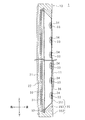
図2及び図3は、表示装置13が備える照明装置22の構成を略示する正面図及び拡大正面図である。
図4は、照明装置22の光源基板33近傍の構成を略示する断面図である。(
FIG. 1 is a cross-sectional view schematically showing a configuration of a
2 and 3 are a front view and an enlarged front view schematically showing the configuration of the
FIG. 4 is a cross-sectional view schematically showing a configuration in the vicinity of the
テレビジョン受信機1は、据え置き式又は壁掛け式等である。テレビジョン受信機1は、受信部11、信号処理部12、及び表示装置13を備えている。
受信部11は、図示しない受信回路が実装された回路基板である。受信回路は、図示しないアンテナを介して外部からテレビジョン放送を受信し、受信したテレビジョン放送に基づく放送信号を出力する。
信号処理部12は、図示しない信号処理回路が実装された回路基板である。信号処理回路は、受信部11が出力した放送信号に所定の信号処理を施すことによって、映像データを出力する。The
The receiving
The
表示装置13は正面視矩形状である。表示装置13は、表示パネル21及び照明装置22と、これらを収容する図示しないキャビネットとを備えている。このキャビネットには、受信部11及び信号処理部12も収容されている。なお、受信部11及び信号処理部12は、表示装置13に外付けされていてもよい。
The
表示パネル21は、矩形板状の液晶表示パネルを用いてなる。表示パネル21は、矩形状の表示領域と、表示領域を囲繞する矩形枠状の額縁領域とを有する。表示領域(及び額縁領域)は表示パネル21の中央部(及び周縁部)に位置する。表示パネル21の表示領域には、信号処理部12が出力した映像データに基づく映像が表示される。
The
照明装置22は、光学シート群30、拡散板31、スペーサ32、複数枚の光源基板33,33,…、複数個の光源34,34,…、収容体35、反射シート36、電源部37、2個の配線部材38,38、複数個の共締め用部材39,39,…、及び2個の給電部材4,4を備えている。
光学シート群30は、夫々光透過性を有する複数枚の光学シートが積層されてなる。各光学シートは、光拡散機能、集光機能、又は偏光機能等を有する。光学シート群30は、表示パネル21の表示領域よりも面積が大きい矩形状になしてある。光学シート群30は、表示パネル21の表示領域の後面に適長離隔して対面配置されている。The
The
拡散板31は光拡散性を有する。拡散板31の光透過率は50%程度である。拡散板31の後面に入射した光の一部は拡散板31を透過し、拡散板31の前面から拡散して出射する。拡散板31の後面に入射した光の他の一部は背面側へ反射する。拡散板31は、光学シート群30よりも面積が大きい矩形状になしてある。拡散板31は、光学シート群30の後面に適長離隔して対面配置されている。
The
スペーサ32は枠状をなし、緩衝性を有する。スペーサ32は、光学シート群30の後面周縁部と拡散板31の前面周縁部との間に介在している。スペーサ32の配置位置は、表示パネル21の額縁領域に対向する位置である。
図2及び図3は、光学シート群30、拡散板31、及びスペーサ32の図示を省略している。The
2 and 3, illustration of the
各光源基板33は短冊状をなす。光源基板33の前面33aには、複数個の光源34,34,…が実装されている。図1及び図3には、18個の光源34,34,…が等配されている場合が例示されている。
先に、光源34について説明する。Each
First, the
各光源34は、発光部341及びレンズ342を有する。
発光部341はLEDを用いてなり、光源基板33の前面33aに実装されている。
レンズ342は、入光部34a及び出光部34bを含む。
入光部34aは円柱状をなし、円柱の後面を光源基板33の前面33aに対面させて光源基板33に取り付けられている。入光部34aの下面中心部には収容凹部34cが設けられており、収容凹部34cに発光部341が収容されている。つまり、発光部341は、レンズ342の入光部34aに覆われている。故に、発光部341が発した光は、入光部34aに入射する。
出光部34bは、入光部34aの円柱の前面に設けられた凸部であり、球面状の表面を有する。入光部34aに入射した光は、レンズ342の内部を透過し、出光部34bの表面から拡散して出射する。Each
The
The
The
The
次に、光源基板33について説明する。
光源基板33の前面33aにおいて、一方の長辺部(即ち幅方向端部)には雄型のコネクタ331が設けられており、他方の長辺部には貫通孔332が設けられている。
更に詳細には、コネクタ331及び貫通孔332夫々の配置位置は、光源基板33の長さ方向中心部である。コネクタ331と貫通孔332とは、光源基板33の幅方向に対向配置されている。光源基板33の幅は光源基板33の長さに比べて短いので、コネクタ331と貫通孔332との離隔距離は短い。換言すれば、貫通孔332はコネクタ331の近傍に配されている。コネクタ331及び貫通孔332夫々は、2個の光源34,34間の中心位置に配されている。Next, the
On the
More specifically, the arrangement position of each of the
なお、光源基板33の長さ方向に係るコネクタ331の配置位置は、長さ方向中心部に限定されず、長さ方向非端部であればよく、より好ましくは長さ方向中央部であればよい。具体的には、コネクタ331は、光源基板33を長さ方向に仮想的に4等分した中央2領域内に配されていればよい。とはいえ、コネクタ331は、本実施の形態のように長さ方向中心部に配されていることが最も望ましい。
The arrangement position of the
コネクタ331は、いわゆる薄型コネクタである。コネクタ331の前面33aからの高さは、レンズ342の入光部34aと出光部34bとの境界部分の前面33aからの高さよりも低い。
The
光源基板33は、夫々の幅方向が上下方向、長さ方向が左右方向、前面33aが拡散板31の後面に対面する向きで、幅方向及び長さ方向夫々に複数枚並置されている。本実施の形態では、20枚の光源基板33,33,…が、10行2列に並置されている場合を例示する。左右方向に隣り合う2枚の光源基板33,33は、長さ方向の端部同士(短辺部同士)が対向配置されている。上下方向に隣り合う2枚の光源基板33,33は、幅方向の端部同士(長辺部同士)が対向配置されている。
A plurality of
最下位置に配されている光源基板33の向きは、最上位置に配された光源基板33が自身の面方向に180 °回転した向き(上下左右逆向き)と同じである。即ち、最上位置の光源基板33の場合、コネクタ331が設けられている長辺部が下辺部であり、貫通孔332が設けられている長辺部が上辺部であるが、最下位置の光源基板33の場合、コネクタ331が設けられている長辺部が上辺部であり、貫通孔332が設けられている長辺部が下辺部である。最上位置及び最下位置以外に配されている光源基板33,33,…夫々の向きは、最上位置の光源基板33と同じである。
The direction of the
収容体35は、底壁351、周壁352、及び支持部353を有する皿状である。収容体35は光源基板33,33,…及び反射シート36等を収容している。
底壁351は、拡散板31よりも面積が小さい矩形状になしてある。底壁351と周壁352との境界部には支持部353が配置してある。支持部353は断面直角三角形状の矩形枠状をなしており、三角形の2つの隣辺に相当する面が底壁351及び周壁352に当接し、斜辺に相当する面が拡散板31側に向いている。
以下では、底壁351における底壁351と支持部353との境界部の近傍を、底壁351の周縁部(上辺部、下辺部、左辺部、及び右辺部)という。The
The
Hereinafter, the vicinity of the boundary portion between the
底壁351の内面には、光源基板33,33,…が、夫々の後面を底壁351に向けて並置してある。光源基板33,33,…は、底壁351の周縁部にも配されている。具体的には、最上位置(又は最下位置)に配された光源基板33の上辺部(又は下辺部)が、底壁351の上辺部(又は下辺部)に接近配置されている。また、左側(又は右側)に配された各光源基板33の左辺部(又は右辺部)が、底壁351の左辺部(又は右辺部)に接近配置されている。
On the inner surface of the
底壁351には、複数個の貫通孔354,354,…が設けられている。
底壁351の後面には、受信部11及び信号処理部12が取り付けられている。
周壁352の前後方向中央部及び支持部353の前端部は、拡散板31の周縁部を支持している。
収容体35の開口は、表示パネル21によって閉塞されている。このために、周壁352の前端部は、表示パネル21の周縁部を支持している。A plurality of through
The receiving
The center part in the front-rear direction of the
The opening of the
反射シート36は光反射性を有する。反射シート36は、光源基板33,33,…夫々の前面33aと収容体35の内面(具体的には底壁351の内面及び支持部353)とを覆う。各光源基板33のコネクタ331及び貫通孔332は反射シート36に覆われるが、光源34,34,…は覆われない。このために、反射シート36における光源34,34,…夫々に対応する部分には、開口が設けられている。また、収容体35の内面の内、拡散板31よりも前側に位置している部分は反射シート36に覆われない。図2及び図3における反射シート36の図示は省略している。
反射シート36には、複数個の貫通孔361,361,…が設けられている。The
The
電源部37は、収容体35の外側にて、底壁351の後面における上下左右方向中央部に取り付けられている。
The
給電部材4,4夫々は、電源部37から各光源基板33へ給電するためのものである。一方の給電部材4は、左側に上下方向に並置されている光源基板33,33,…(即ち左側1列の光源基板33,33,…)に対する給電に用いられ、他方の給電部材4は、右側に上下方向に並置されている光源基板33,33,…(即ち右側1列の光源基板33,33,…)に対する給電に用いられる。左右の給電部材4,4は同様の構成である。
Each of the
給電部材4は、ベースフィルムが透光性を有するフレキシブルプリント基板を用いてなり、底壁351と反射シート36との間に配されている。給電部材4は十分に薄いので、給電部材4が介在しているせいで底壁351と反射シート36とが無用に離隔する虞はない。
給電部材4は、ポリエチレンテレフタレート樹脂又はポリエチレンナフタレート樹脂を含んでなる。故に、給電部材4は、ポリイミド樹脂を含んでなる一般的なフレキシブルプリント基板に比べて安価である。また、ポリエチレンテレフタレート樹脂又はポリエチレンナフタレート樹脂を用いれば、透光性を有するフレキシブルプリント基板を容易且つ安価に得ることができる。The
The
給電部材4は本体部41と複数個の腕状片42,42,…とを有する。
本体部41は、上下方向に長い帯状になしてある。
腕状片42,42,…の個数は、左側(又は右側)1列の光源基板33,33,…の枚数と同一である。各腕状片42は、長さ方向が左右方向である矩形舌状の基端側舌状片42aと、長さ方向が上下方向である矩形舌状の先端側舌状片42bとを有する。The
The
The number of arm-shaped
各基端側舌状片42aは、本体部41から本体部41の幅方向に突出する。つまり、基端側舌状片42a,42a,…は、上下方向に並設されている。最上位置(又は最下位置)の基端側舌状片42aは、本体部41の最上端部(又は最下端部)に突設されている。各基端側舌状片42aが本体部41から突出する方向、及び突出する長さは同じである。
Each base-side tongue-
各先端側舌状片42bは、基端側舌状片42aの先端部から本体部41の長さ方向に突出する。つまり、複数個の先端側舌状片42b,42b,…は、上下方向に一列に並んでいる。各先端側舌状片42bが基端側舌状片42aから突出する長さは同じである。最上位置の先端側舌状片42bと最下位置の先端側舌状片42bとは、互いに離反する上下方向(前者は上方向、後者は下方向)に突出している。最上位置及び最下位置の先端側舌状片42b,42b以外の先端側舌状片42b,42b,…は、最上位置及び最下位置の何れか一方の先端側舌状片42bの突出方向と同じ方向に突出している(本実施の形態では上方向)。先端側舌状片42bの先端部には、貫通孔43が設けられている。
Each distal-side tongue-
給電部材4はフレキシブルなので、各基端側舌状片42aは、本体部41との境界部を中心に配置を調整することができ、各先端側舌状片42bは、基端側舌状片42aとの境界部を中心に配置を調整することができる。故に、例えば基端側舌状片42a(又は先端側舌状片42b)は、本体部41(又は基端側舌状片42a)に対して斜めに並置することができる。
Since the
先端側舌状片42bは、光源基板33の前面33aにおける2個の光源34,34間であって、コネクタ331及び貫通孔332が設けられている部分を覆う。
本体部41は、最上位置及び最下位置の光源基板33,33を除く全ての光源基板33,33,…を部分的に覆う。更に詳細には、各光源基板33の前面33aにおける2個の光源34,34間であって、コネクタ331及び貫通孔332が設けられている部分以外を覆う。The front-side tongue-
The
給電部材4の一面には、複数個の光源接続部44,44,…及び図示しない電源接続部が設けられている。また、給電部材4には、電源接続部と各光源接続部44とを個別に接続する図示しない給電経路が形成されている。給電経路は透光性を有していてもよく、遮光性を有していてもよい。
光源接続部44,44,…及び電源接続部が給電部材4の同一面に設けられているので、これらが給電部材4の異なる面に個別に設けられている場合に比べて、給電部材4の製造コストは低減される。A plurality of light
Since the light
光源接続部44,44,…は腕状片42,42,…に設けられている。更に詳細には、各光源接続部44は、先端側舌状片42bにおける貫通孔43よりも先端側舌状片42bの基端部側に設けられている。光源接続部44と貫通孔43との離隔距離は、光源基板33におけるコネクタ331と貫通孔332との離隔距離に対応する。
The light
光源接続部44は、コネクタ331に対応する雌型のコネクタである。光源接続部44は、コネクタ331に前側から嵌め合わされることによってコネクタ331に電気的に接続されている。
光源接続部44が腕状片42に設けられているので、光源接続部44が本体部41に設けられている場合に比べて、光源接続部44の配置位置の調整は容易である。故に、寸法誤差又は配置時のトラブル等による本体部41と光源基板33,33,…との相対的な位置ずれ、或いは温度変化に起因する膨張/収縮による位置ずれ等が生じたとしても、光源接続部44とコネクタ331とを容易に接続することができ、また、無用に接続が解除されることが抑制される。The light
Since the light
製造者が光源接続部44をコネクタ331に接続する作業は作業性が高い。何故ならば、給電部材4は透光性を有しているので、給電部材4でコネクタ331を覆っても、給電部材4を通してコネクタ331の配置位置を容易に確認することができるからである。
The work of connecting the light
給電部材4の電源接続部は、本体部41の上下方向中央部に設けられている。給電部材4は、電源接続部と配線部材38とを介して電源部37に電気的に接続されている。この結果、各光源基板33と電源部37とは、給電部材4を介して個別に電気的に接続されている。
配線部材38は、フレキシブルプリント基板又はフラットケーブル等を用いてなり、底壁351に設けられている図示しない貫通孔を貫通して収容体35の内外に引き出されている。
なお、給電部材4の電源接続部が、底壁351に設けられている図示しない貫通孔を貫通して収容体35の外部へ突出していてもよい。この場合、配線部材38を収容体35の内部へ引き入れる必要はない。The power supply connection portion of the
The
Note that the power supply connecting portion of the
反射シート36の貫通孔361と給電部材4の貫通孔43と光源基板33の貫通孔332と収容体35の貫通孔354とは前後方向に対向している。貫通孔361,43,332,354夫々は正面視円形状であり、互いに同径である。
反射シート36、給電部材4、及び光源基板33は、共締め用部材39を用いて、底壁351に共締めされる。
共締め用部材39は、光反射性を有する頭部391と、先端部が二股状の脚部392とを有する。
脚部392の二股状部分は弾性を有し、互いに離反している。脚部392は、反射シート36との貫通孔361、給電部材4の貫通孔43、光源基板33の貫通孔332、底壁351の貫通孔354に前側からこの順に貫通している。The through
The
The
The bifurcated portions of the
貫通孔361,43,332,354への挿入時には、脚部392の二股状部分は強制的に接近させられるが、脚部392の先端部が底壁351の背面側へ突出したときに弾性復元力によって離反する。このとき、脚部392の二股状部分が貫通孔354の周縁部に係合するので、脚部392が貫通孔361,43,332,354から無用に抜脱されることが抑制される。また、このとき、頭部391が、底壁351との間で反射シート36、給電部材4、及び光源基板33を挟持する。
以上の結果、反射シート36、給電部材4、及び光源基板33が底壁351に共締めされる。At the time of insertion into the through
As a result, the
反射シート36、給電部材4、及び光源基板33は、共通の共締め用部材39によって底壁351に共締めされる。故に、これらが相異なる固定用部材によって底壁351に個別に固定される場合に比べて、部品数及び部品点数を削減することができる。
The
反射シート36は、給電部材4に被覆されたコネクタ331を更に覆っている。従って、反射シート36におけるコネクタ331近傍の部分は、コネクタ331から遠い部分に比べて、前側へ湾曲し易い。つまり、コネクタ331と給電部材4とが前後方向に接続されているせいで、いわゆる反射シート36の浮きが生じ易い。
The
反射シート36の浮きは、反射シート36、給電部材4、及び光源基板33の底壁351に対する共締めによって抑制される。何故ならば、共締め位置とコネクタ位置との離隔距離が、光源基板33の幅の長さ未満だからである。換言すれば、反射シート36は、浮き易い部分の近傍が、共締め用部材39によって底壁351側に押し付けられるので、共締め用部材39による押しつけがない場合よりも浮き難い。
給電部材4は共締め用部材39によって底壁351側に押し付けられるので、光源接続部44がコネクタ331に押し付けられる。従って、光源接続部44がコネクタ331から脱落して両者の電気的な接続が無用に解除されてしまうことが抑制される。The floating of the
Since the
なお、給電部材4の各基端側舌状片42a又は本体部41は、反射シート36と共に、底壁351に共締めされていてもよい。このとき、基端側舌状片42a又は本体部41が底壁351に密着固定されるので、給電部材4が全体的に底壁351側へ付勢される。すると、光源接続部44がコネクタ331に押し付けられるので、給電部材4と光源基板33との接続が無用に解除されることが抑制される。
反射シート36と共に基端側舌状片42aが底壁351に共締めされる場合、共締め位置が光源接続部44の近傍であれば、反射シート36の浮きを抑制することができる。Each base-side tongue-
When the base side tongue-
以上のような照明装置22の場合、電源部37から配線部材38,38、給電部材4,4、及び光源基板33,33,…を介して各光源34へ給電される。給電部材4,4及び光源基板33,33,…夫々(並びにフレキシブルプリント基板を用いてなる配線部材38,38)には、給電経路をパターン形成することができる。故に、電源部37から配線部材38、給電部材4,4に替わる複数本の給電線、及び光源基板33,33,…を介して各光源34へ給電される場合に比べて、容易に配線することができる。
In the case of the
光源34,34,…が発した光の一部は、直接的に拡散板31へ入射して拡散板31を透過する。また、光源34,34,…が発した光の他の一部は、拡散板31と反射シート36又は共締め用部材39との間で反射を繰り返してから拡散板31へ入射して拡散板31を透過する。拡散板31を透過した光は光学シート群30を透過する。この結果、照明装置22は表示パネル21を背面側から照明する。
A part of the light emitted from the
光源34からの出光は、反射シート36又は共締め用部材39によって阻害されることはない。このために、反射シート36における光源基板33の前面33aを覆う部分、及び共締め用部材39夫々の前面33aからの高さは、レンズ342の入光部34aと出光部34bとの境界部分の光源基板33の前面33aからの高さよりも低くなるようにしてある。
The light emitted from the
ここで、最上位置の光源基板33と最下位置の光源基板33とが上下左右逆向きにしてある理由を説明する。
最上位置の光源基板33からは、腕状片42が下向きに引き出されている。一方、最下位置の光源基板33からは、腕状片42が上向きに引き出されている。つまり、2枚の光源基板33,33の何れからも、腕状片42は底壁351の上下方向中央部側に引き出されている。このため、底壁351の上辺部及び下辺部に光源基板33,33を配置することができる。
仮に、最下位置の光源基板33の向きを最上位置の光源基板33と同じにすると、腕状片42を光源基板33からの下辺部に引き出すことになるので、底壁351の下辺部に光源基板33を配置することができない。Here, the reason why the
From the uppermost
If the orientation of the lowermost
ところで、各光源基板33から腕状片42が引き出される方向は上下方向なので、腕状片42を底壁351の左辺部又は右辺部に引き出す必要がない。故に、光源基板33の端部を底壁351の左辺部又は右辺部に配置することができる。
即ち、底壁351の周縁部全てに光源基板33,33,…を配置することができる。換言すれば、底壁351の中央部のみならず、周縁部にも光源34,34,…を配置することができる。従って、表示パネル21の表示領域の周縁部の輝度を向上させることができる。また、底壁351上のスペースが無駄にならないので、底壁351に配置される光源基板33,33,…の枚数を増加させることができる。その分、多くの光源34,34,…を配置することができるので、表示パネル21の表示領域全体の輝度を向上させることができる。By the way, since the arm-shaped
That is, the
ところで、最上位置の光源基板33と最下位置の光源基板33とは共通化されている。何故ならば、各光源基板33は、コネクタ331の配置位置に関して左右対称なので、2枚の光源基板33,33の内、一方の向きを上下左右逆向きにしても、給電部材4から各コネクタ331までの距離を略同じにすることができるからである。
光源基板33,33,…の共通化は、部品点数の削減につながるので、大量生産及び部品管理の簡素化等によるコスト削減を図ることができる。By the way, the uppermost
Since the sharing of the
仮に、コネクタ331が光源基板33の長さ方向一端部に設けられている場合、2枚の光源基板33,33の内、一方の向きを上下左右逆向きにすると、コネクタ331が右端部に位置する場合と左端部に位置する場合とで給電部材4から各コネクタ331までの距離が大幅に異なる。すると、給電部材4の各腕状片42の本体部41からの突出長さを個別に変えておく必要があるので、給電部材4の製造手順が煩雑になる。
If the
この問題を解消するために、コネクタ331が下辺部の右端部に位置する光源基板33を最上位置配置用とし、コネクタ331が上辺部の右端部に位置する光源基板33を最下位置配置用とすることが考えられる。しかしながら、この場合には、光源基板33,33,…を共通化することができない。
コネクタ331を光源基板33の上下左右中心部に配した場合、光源基板33のコネクタ331の配置位置に係る対称性が向上する。しかしながら、この場合には貫通孔332を適切な位置に設けることができない可能性がある。また、コネクタ331と光源接続部44とを接続させるために、給電部材4は無用に多く光源基板33を覆わなければならない。In order to solve this problem, the
When the
なお、光源基板33,33,…の並置状態は本実施の形態のものに限定されず、例えば光源基板33,33,…が、長さ方向及び幅方向を上下方向及び左右方向に向けて並置されてもよい。
The juxtaposed state of the
給電部材4,4夫々の左右方向の配置位置は、底壁351の周縁部以外であれば特に限定されない。また、給電部材4の電源接続部の配置位置も、特に限定されない。これらの配置は、電源部37からの離隔距離、配線部材38の配置との兼ね合い、又は他部材との干渉等を考慮して、適宜に決定されたものであればよい。つまり、給電部材4及び電源接続部の配置位置は、自由度が高い。
The arrangement positions of the
コネクタ331と光源接続部44との接続方向は、前面33aに交差する方向に限定されず、前面33aに沿う方向でもよい。
とはいえ、コネクタ331と光源接続部44との接続方向は、前面33aに沿う方向よりも、前面33aに交差する方向の方が望ましい。何故ならば、照明装置22は、前面33aに沿う方向の空間的な余裕に比べれば、前面33aに交差する方向の空間的な余裕の方が大きいからである。この結果、照明装置22が無用に大型化することが抑制される。The connection direction between the
However, the direction of connection between the
給電部材4は、フラットケーブルを用いてなる構成でもよい。しかしながら、フラットケーブルには貫通孔を設けることができないので、共締め以外の手法(例えば両面テープを用いた接着、クリップを用いた挟持、又は樹脂モールドによる封止)で給電部材4を底壁351に取り付ける必要がある。ただし、この場合であっても光源基板33と反射シート36とを底壁351に共締めすることはできる。
また、給電部材4は、透光性を有していなくてもよい。The
Further, the
(実施の形態 2.)
図5及び図6は、本発明の実施の形態2に係る表示装置13が備える照明装置22の構成を略示する正面図及び拡大正面図である。図5及び図6は、実施の形態1の図2及び図3に対応する。
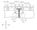
図7及び図8は、照明装置22の光源基板33近傍及び電源部37近傍の構成を略示する断面図である。
本実施の形態の表示装置13及び照明装置22は、実施の形態1の表示装置13及び照明装置22と略同様の構成である。以下では、実施の形態1との差異について説明し、その他、実施の形態1に対応する部分には同一符号を付してそれらの説明を省略する。(Embodiment 2.)
5 and 6 are a front view and an enlarged front view schematically showing the configuration of the
7 and 8 are cross-sectional views schematically showing configurations in the vicinity of the
The
本実施の形態の光源基板33には、実施の形態1のコネクタ331及び貫通孔332は設けられていない。
光源基板33の前面33aには、コネクタ333が設けられている。コネクタ333は、配置位置を除いて、実施の形態1のコネクタ331と同様の構成である。The
A
コネクタ333は、光源基板33における一方の短辺部(即ち長さ方向端部)の幅方向中心部に配されている。左右方向に隣り合う2枚の光源基板33,33のコネクタ333,333は、光源基板33,33の互いに対向配置された端部に配されている。即ち、左側1列に含まれている各光源基板33の場合、コネクタ333は右辺部に配されている。右側1列に含まれている各光源基板33の場合、コネクタ333は左辺部に配されている。
The
収容体35の底壁351には、実施の形態1の貫通孔354,354,…は設けられていない。
底壁351には貫通孔355が設けられている。貫通孔355の配置位置は、底壁351の上下左右方向中央部である。
反射シート36には、実施の形態1の貫通孔361,361,…は設けられていない。各光源基板33のコネクタ333は反射シート36に覆われる。図7及び図8における反射シート36の図示は省略している。In the
A through
The
電源部37は、雄型のコネクタ371を有している。コネクタ371は、背面側から底壁351の貫通孔355に挿入されて、収容体35の内部に突出している。ただし、コネクタ371の底壁351の前面からの高さは、光源基板33の底壁351の前面からの高さよりも低い。
本実施の形態の照明装置22は配線部材38,38を備えておらず、給電部材4,4に替えて給電部材5を備えている。The
The
給電部材5は、電源部37から各光源基板33へ給電するためのものである。実施の形態1では2個の給電部材4,4を左右に配して左右2列の光源基板33,33,…夫々へ給電するが、本実施の形態では1個の給電部材5を左右方向中央部に配して左右2列の光源基板33,33,…へ給電する。
The
給電部材5は、ベースフィルムが透光性を有するフレキシブルプリント基板を用いてなり、底壁351と反射シート36との間に配されている。給電部材5は十分に薄いので、給電部材5が介在しているせいで底壁351と反射シート36とが無用に離隔する虞はない。
給電部材5は、ポリエチレンテレフタレート樹脂又はポリエチレンナフタレート樹脂を含んでなる。故に、給電部材5は、ポリイミド樹脂を含んでなる一般的なフレキシブルプリント基板に比べて安価である。また、ポリエチレンテレフタレート樹脂又はポリエチレンナフタレート樹脂を用いれば、透光性を有するフレキシブルプリント基板を容易且つ安価に得ることができる。The
The
給電部材5は本体部51と複数個の腕状片521,521,…と複数個の舌状片522,522,…とを有する。腕状片521,521,…の個数は、光源基板33,33,…の枚数と同一である。舌状片522,522,…の個数は、例えば4個である。
The
給電部材5の一面には、複数個の光源接続部54,54,…と、電源接続部55とが設けられており、電源接続部55と各光源接続部54とを個別に接続する給電経路が形成されている。光源接続部54,54,…及び電源接続部55が給電部材5の同一面に設けられているので、これらが給電部材5の異なる面に個別に設けられている場合に比べて、給電部材5の製造コストは低減される。光源接続部54,54,…の個数は腕状片521,521,…の個数と同じである。
A plurality of light
本体部51は、上下方向に長い帯状になしてある。本体部51の配置位置は、左側1列の光源基板33,33,…と右側1列の光源基板33,33,…との間である。つまり、本体部51は光源基板33を被覆しない。
本体部51の上端部(又は下端部)は、最上位置(又は最下位置)にて左右方向に隣り合う2枚の光源基板33,33間に配されている。The
The upper end (or lower end) of the
本体部51の上下方向中央部には、電源接続部55が設けられている。電源接続部55は、電源部37のコネクタ371に対応する雌型のコネクタ551と、コネクタ551を支持する接続支持部552とを有する。電源接続部55は、コネクタ551がコネクタ371に前側から嵌め合わされることによってコネクタ371に電気的に接続されている。
A power
接続支持部552は、コネクタ551を本体部51から後側に離隔して配置し、且つ、コネクタ551と本体部51に形成されている給電経路とを電気的に接続するためのものである。このように、コネクタ551と本体部51との間に接続支持部552が介在しているので、電源接続部55がコネクタ371に接続されているせいで本体部51が後側へ無用に湾曲することが抑制される。
以上のように、給電部材5は、電源接続部55とコネクタ371とを介して電源部37に電気的に接続されている。この結果、各光源基板33と電源部37とは、給電部材5を介して個別に電気的に接続されている。The
As described above, the
給電部材5の各腕状片521は、長さ方向が左右方向の矩形舌状である。腕状片521,521,…は、2個ずつ左右方向の離反方向に向けて、本体部51から突出する。つまり、腕状片521,521,…は、10行2列に並設されている。最上位置(又は最下位置)の腕状片521は、本体部51の最上端部(又は最下端部)に突設されている。各腕状片521が本体部51から突出する方向、及び突出する長さは同じである。
給電部材5はフレキシブルなので、各腕状片521は、本体部51との境界部を中心に配置を調整することができ、故に、腕状片521は、本体部51に対して斜めに並置することができる。Each arm-shaped
Since the
光源接続部54は、腕状片521の先端部に設けられている。光源接続部54は、コネクタ333に対応する雌型のコネクタである。光源接続部54は、コネクタ333に前側から嵌め合わされることによってコネクタ333に電気的に接続されている。
光源接続部54が腕状片521に設けられているので、光源接続部54が本体部51に設けられている場合に比べて、光源接続部54の配置位置の調整は容易である。故に、寸法誤差又は配置時のトラブル等による本体部51と光源基板33,33,…との相対的な位置ずれ、或いは温度変化に起因する膨張/収縮による位置ずれ等が生じたとしても、光源接続部54とコネクタ333とを容易に接続することができ、また、無用に接続が解除されることが抑制される。The light
Since the light
製造者が光源接続部54をコネクタ333に接続する作業は作業性が高い。何故ならば、給電部材5は透光性を有しているので、給電部材5でコネクタ333を覆っても、給電部材5を通してコネクタ333の配置位置を容易に確認することができるからである。
各腕状片521は、光源基板33のコネクタ333が設けられている部分を覆う。コネクタ333は光源基板33の短辺部に設けられているので、給電部材5が光源基板33を無用に被覆することはない。The work of connecting the light
Each arm-shaped
給電部材5の各舌状片522は、長さ方向が左右方向の矩形舌状である。舌状片522,522,…は、2個ずつ左右方向の離反方向に向けて、本体部51から突出する。上側(又は下側)の舌状片522は、最上位置(又は最下位置)の光源基板33と、これの下側(又は上側)に隣り合う光源基板33との間に配されている。つまり、各舌状片522は光源基板33を被覆しない。
Each tongue-
舌状片522の先端部には、図示しない貫通孔が設けられている。この貫通孔に対応する図示しない貫通孔が、反射シート36に設けられている。舌状片522,522,…と反射シート36とは、共締め用部材39,39,…を用いて、底壁351に共締めされる。故に、これらが相異なる固定用部材によって底壁351に個別に固定される場合に比べて、部品数及び部品点数を削減することができる。
A through hole (not shown) is provided at the tip of the tongue-
反射シート36との共締めによって、各舌状片522は底壁351に密着固定される。この結果、給電部材5が底壁351側に付勢されて光源接続部54がコネクタ333に押し付けられるので、光源接続部54がコネクタ333から脱落して両者の電気的な接続が無用に解除されてしまうことも抑制される。
なお、舌状片522,522,…は反射シート36とは無関係に、又は共締め用部材39,39,…以外の固定用部材を用いて、底壁351に密着固定されてもよい。Each tongue-
The tongue-
以上のような照明装置22の場合、電源部37から給電部材5及び光源基板33,33,…を介して各光源34へ給電される。
この結果、照明装置22は、実施の形態1の照明装置22と同様の作用効果を奏することができる。しかも、実施の形態1の照明装置22は2個の給電部材4,4を備えており、配線部材38,38を介して電源部37に接続されているのに対し、本実施の形態の照明装置22は1個の給電部材5を備えており、直接的に電源部37に接続されているので、部品数を削減することができる。In the case of the
As a result, the illuminating
ところで、各光源基板33から腕状片521が引き出される方向は左右方向なので、腕状片521を底壁351の上辺部又は下辺部に引き出す必要がない。また、各光源基板33のコネクタ333は、光源基板33における底壁351の左右方向中央部側の端部に設けられている。従って、腕状片521を底壁351の左辺部又は右辺部に引き出す必要がない。
By the way, since the arm-shaped
以上のように、給電部材5は、最上位置(又は最下位置)の光源基板33,33よりも底壁351の上辺部側(又は下辺部側)には配されていない。また、給電部材5は、左側(又は右側)1列の光源基板33,33,…よりも底壁351の左辺部側(又は右辺部側)には配されていない。
以上の結果、底壁351の周縁部に光源基板33,33,…を配置することができるので、底壁351の周縁部に光源34,34,…を配置することができる。従って、表示パネル21の表示領域の周縁部の輝度を向上させることができる。また、底壁351上のスペースが無駄にならないので、底壁351に配置される光源基板33,33,…の枚数を増加させることができる。その分、多くの光源34,34,…を配置することができるので、表示パネル21の表示領域全体の輝度を向上させることができる。As described above, the
As a result, the
(実施の形態 3.)
図9は、本発明の実施の形態3に係る表示装置13が備える照明装置22の電源部37近傍の構成を略示する断面図である。図9は、実施の形態2の図7及び図8に対応する。
本実施の形態の表示装置13及び照明装置22は、実施の形態2の表示装置13及び照明装置22と略同様の構成である。以下では、実施の形態2との差異について説明し、その他、実施の形態2に対応する部分には同一符号を付してそれらの説明を省略する。(
FIG. 9 is a cross-sectional view schematically showing a configuration in the vicinity of the
The
給電部材5の電源接続部55は、実施の形態2のコネクタ551に相当するものが本体部51に直接的に設けられており、実施の形態2の接続支持部552を有していない。このため、本実施の形態の給電部材5は、実施の形態2のものより簡易な構成である。
電源部37のコネクタ371は、底壁351の貫通孔355に挿入されておらず、収容体35の外部に位置している。The power
The
本実施の形態の照明装置22は配線部材38を備えている。配線部材38は、底壁351の貫通孔355を通して収容体35の内外に引き出されており、給電部材5の電源接続部55と電源部37のコネクタ371とを電気的に接続している。このために、配線部材38は、電源接続部55に対応する雄型のコネクタ381と、コネクタ371に対応する雌型のコネクタ382とを有する。
この結果、各光源基板33と電源部37とは、給電部材5を介して個別に電気的に接続されている。The
As a result, each
以上のような照明装置22は、実施の形態2の照明装置22と同様の作用効果を奏する。
また、コネクタ371と電源接続部55との間に配線部材38が介在しているので、電源接続部55がコネクタ371に接続されているせいで本体部51が後側へ無用に湾曲することが抑制される。The
Further, since the
次に、本発明の実施の形態1〜3についてまとめる。
Next,
本発明に係る照明装置22は、皿状の収容体35と、夫々の一面に光源34が実装されており、前記収容体35の底壁351の内面に並置された複数枚の光源基板33と、前記一面及び前記収容体35の内面を覆い、光を反射する反射シート36と、電源部37とを備える照明装置22において、前記一面に設けられたコネクタ331,333と、フレキシブルプリント基板を用いてなり、前記底壁351及び前記反射シート36の間に配されており、前記電源部37から前記光源基板33へ給電するための給電部材4,5と、該給電部材4,5に設けられており、前記コネクタ331,333と電気的に接続される光源接続部44,54とを備えることを特徴とする。
The illuminating
本発明に係る照明装置22は、前記給電部材4,5は帯状をなし、前記電源部37に電気的に接続されており、前記光源基板33は短冊状をなし、前記給電部材4,5の長さ方向に沿って前記光源基板33の幅方向に並置されていることを特徴とする。
In the illuminating
本発明に係る照明装置22は、前記給電部材5は帯状をなし、前記電源部37に電気的に接続されており、前記給電部材5の幅方向に2枚の前記光源基板33の端部同士が隣り合い、前記コネクタ333は、前記端部に配されていることを特徴とする。
In the illuminating
本発明に係る照明装置22は、前記光源34は、前記一面に実装された発光部341と、該発光部341を覆い、該発光部341が発した光が入射する入光部34a及び該入光部34aに入射した光が出射する出光部34bを含むレンズ342とを有し、前記反射シート36の前記一面を覆う部分の前記一面からの高さは、前記出光部34bの前記一面からの高さよりも低いことを特徴とする。
In the
本発明に係る照明装置22は、前記底壁351には貫通孔355が設けられており、前記電源部37は、前記底壁351の外面に配されており、前記貫通孔355を通して前記給電部材5に電気的に接続されていることを特徴とする。
In the
本発明に係る照明装置22は、前記給電部材5の一面には、前記光源接続部54、及び、前記電源部37と電気的に接続するための電源接続部55が設けられていることを特徴とする。
The illuminating
本発明に係る照明装置22は、前記給電部材5の前記光源接続部54が設けられている部分は前記コネクタ333を被覆しており、前記給電部材5は舌状片522を有し、該舌状片522は前記底壁351に密着固定してあることを特徴とする。
In the
本発明に係る照明装置22は、前記給電部材4,5は、帯状の本体部41,51と、本体部41,51に突設された複数個の腕状片42,521とを有し、該腕状片42,521に前記光源接続部44,54が設けられていることを特徴とする。
In the
本発明に係る照明装置22は、各光源基板33と前記電源部37とは、前記給電部材4,5を介して個別に電気的に接続されていることを特徴とする。
The illuminating
本発明に係る表示装置13は、本発明に係る照明装置22と、該照明装置22によって背面側から照明される表示パネル21とを備えることを特徴とする。
The
テレビジョン受信機は、本発明に係る表示装置13と、テレビジョン放送を受信する受信部11とを備え、該受信部にて受信したテレビジョン放送に基づいて、前記表示装置13に映像を表示するようにしてあることを特徴とする。
The television receiver includes a
本発明にあっては、給電部材がフレキシブルプリント基板を用いてなる。故に、各光源基板に複数本の給電線を電気的に接続する場合に比べて、配線が簡易である。 In the present invention, the power supply member uses a flexible printed board. Therefore, the wiring is simpler than in the case where a plurality of power supply lines are electrically connected to each light source substrate.
本発明にあっては、帯状の給電部材の長さ方向に沿って、短冊状の光源基板が幅方向に並置される。従って、帯状の給電部材の長さ方向に沿って短冊状の光源基板が長さ方向に並置される場合よりも、給電部材を介して給電される光源基板の枚数を容易に増加させることができる。 In the present invention, the strip-shaped light source substrates are juxtaposed in the width direction along the length direction of the belt-shaped power supply member. Therefore, the number of light source substrates fed via the power feeding member can be increased more easily than when strip-shaped light source substrates are juxtaposed along the length direction of the belt-shaped power feeding member. .
本発明にあっては、隣り合う2枚の光源基板の対向端部夫々にコネクタが設けられているので、隣り合う2枚の光源基板の対向端部以外にコネクタが設けられている場合に比べて、2倍の枚数の光源基板を給電部材に容易に接続することができる。従って、光源基板の枚数が同じであれば、給電部材数を削減することができる。 In the present invention, the connector is provided at each of the opposing end portions of the two adjacent light source boards, so that compared to the case where the connector is provided at other than the opposing end portions of the two adjacent light source boards. Thus, twice as many light source substrates can be easily connected to the power supply member. Therefore, if the number of light source substrates is the same, the number of power supply members can be reduced.
本発明にあっては、反射シートが、光源の出光部より光源基板側に配されている。故に、反射シート、及び反射シートに覆われている給電部材又はコネクタ等が、光源からの出光を阻害することが抑制される。 In the present invention, the reflection sheet is arranged on the light source substrate side from the light output portion of the light source. Therefore, the reflection sheet and the power supply member or the connector covered with the reflection sheet are prevented from inhibiting light output from the light source.
本発明にあっては、収容体の底壁に設けられた貫通孔を通して、簡易な構成で電源部と光源基板とを電気的に接続することができる。 In the present invention, the power supply unit and the light source substrate can be electrically connected with a simple configuration through the through hole provided in the bottom wall of the container.
本発明にあっては、光源接続部及び電源接続部が給電部材の同一面に設けられている。故に、これらが異なる面に設けられている場合よりも給電部材の製造コストを低減することができる。 In the present invention, the light source connecting portion and the power source connecting portion are provided on the same surface of the power feeding member. Therefore, the manufacturing cost of the power feeding member can be reduced as compared with the case where they are provided on different surfaces.
本発明にあっては、舌状片が収容体の底壁に密着固定してあるので、給電部材が全体的に底壁側へ付勢される。すると、光源接続部がコネクタに押し付けられるので、給電部材とコネクタとの接続が無用に解除されることが抑制される。 In the present invention, since the tongue-like piece is tightly fixed to the bottom wall of the container, the power feeding member is generally biased toward the bottom wall. Then, since the light source connection portion is pressed against the connector, it is possible to suppress the unnecessary connection between the power supply member and the connector.
本発明にあっては、本体部に比べて、個々の腕状片の配置は自由度が高い。故に、例えば本体部と光源基板との間に位置ずれが生じた場合でも、生じた位置ずれを腕状片の配置によって容易に吸収することができる。従って、本体部に光源接続部が設けられている場合に比べて、腕状片に設けられている光源接続部とコネクタとの接続は容易であり、しかも、これらの接続が無用に解除されてしまうことが抑制される。 In the present invention, the arrangement of the individual arm-like pieces has a higher degree of freedom than the main body. Therefore, for example, even when a positional shift occurs between the main body and the light source substrate, the generated positional shift can be easily absorbed by the arrangement of the arm-shaped pieces. Therefore, compared with the case where the light source connection part is provided on the main body part, the connection between the light source connection part provided on the arm-shaped piece and the connector is easy, and these connections are unnecessarily released. Is suppressed.
本発明にあっては、各光源基板と前記電源部とが、給電部材を介して個別に電気的に接続されているので、配線を容易にしつつ、ローカルディミングに対応することができる。 In the present invention, each light source substrate and the power supply unit are individually electrically connected via the power supply member, so that it is possible to cope with local dimming while facilitating wiring.
(実施の形態 4.)
図10は、本発明の実施の形態4に係る表示装置13が備える照明装置22の構成を略示する拡大正面図である。
図11は、照明装置22の光源基板33近傍の構成を略示する断面図である。
図10及び図11は、実施の形態1の図3及び図4に対応する。
本実施の形態の表示装置13及び照明装置22は、実施の形態1の表示装置13及び照明装置22と略同様の構成である。以下では、実施の形態1との差異について説明し、その他、実施の形態1に対応する部分には同一符号を付してそれらの説明を省略する。(
FIG. 10 is an enlarged front view schematically showing the configuration of the
FIG. 11 is a cross-sectional view schematically showing a configuration in the vicinity of the
10 and 11 correspond to FIGS. 3 and 4 of the first embodiment.
The
給電部材4が有する各腕状片42は、基端側舌状片42aと、実施の形態1の先端側舌状片42bに対応する先端側舌状片42cとを有する。
先端側舌状片42cの長さは、実施の形態1の先端側舌状片42bの半分程度である。先端側舌状片42cには実施の形態1の貫通孔43と同様の貫通孔は設けられていない。先端側舌状片42cの先端部には、光源接続部44が設けられている。本実施の形態でも、光源接続部44はコネクタ331に電気的に接続されている。Each arm-
The length of the
先端側舌状片42cは、光源基板33の前面33aにおける2個の光源34,34間であって、コネクタ331が設けられている部分を覆うが、貫通孔332が設けられている部分は覆わない。コネクタ331は光源基板33の長辺部(即ち、光源基板33の幅方向端部)に設けられているので、給電部材4が光源基板33を無用に被覆することはない。
The front-side tongue-
光源基板33及び反射シート36は、共締め用部材39を用いて、底壁351に共締めされる。しかしながら、給電部材4が、光源基板33と共に底壁351に共締めされることはない。
The
給電部材4の各基端側舌状片42a及び反射シート36は、共締め用部材39を用いて、底壁351に共締めされる。このとき、基端側舌状片42aが底壁351に密着固定されるので、給電部材4が全体的に底壁351側へ付勢される。すると、光源接続部44がコネクタ331に押し付けられるので、給電部材4と光源基板33との接続が無用に解除されることが抑制される。
反射シート36と共に基端側舌状片42aが底壁351に共締めされる場合、共締め位置が光源接続部44の近傍であれば、反射シート36の浮きを抑制することができる。
以上のような照明装置22は、実施の形態1の照明装置22と同様の作用効果を奏する。Each base-side tongue-
When the base side tongue-
The
(実施の形態 5.)
図12は、本発明の実施の形態5に係る表示装置13が備える照明装置22の構成を略示する拡大正面図である。
図12は、実施の形態4の図10に対応する。
本実施の形態の表示装置13及び照明装置22は、実施の形態4の表示装置13及び照明装置22と略同様の構成である。以下では、実施の形態4との差異について説明し、その他、実施の形態4に対応する部分には同一符号を付してそれらの説明を省略する。(
FIG. 12 is an enlarged front view schematically showing the configuration of the
FIG. 12 corresponds to FIG. 10 of the fourth embodiment.
The
給電部材4が有する本体部41は、光源基板33,33,…と底壁351との間に配されている。従って、給電部材4が光源基板33を無用に被覆することはない。
給電部材4は十分に薄いので、給電部材4が介在しているせいで底壁351と各光源基板33とが無用に離隔する虞はない。
以上のような照明装置22は、実施の形態4の照明装置22と同様の作用効果を奏する。The
Since the
The
本発明の実施の形態1〜6に係る表示装置は、テレビジョン受信機1として構成されている表示装置13に限定されず、電子看板、又は、パーソナルコンピュータ用のモニタ等として構成されていてもよい。
本発明の実施の形態1〜6に係る照明装置は、表示装置13に組み込まれる構成に限定されない。例えば、照明装置は、携帯電話機又は携帯情報端末装置等が備える表示部のバックライトユニットとして構成されていてもよい。或いは、照明装置は、シーリングライト又は壁掛け照明器具等として構成されていてもよい。The display device according to the first to sixth embodiments of the present invention is not limited to the
The illumination devices according to
最後に、本発明の実施の形態1,4,5についてまとめる。
Finally,
本発明に係る照明装置22は、皿状の収容体35と、夫々の一面に光源34が実装されており、前記収容体35の底壁351の内面に並置された複数枚の光源基板33と、前記一面及び前記収容体35の内面を覆い、光を反射する反射シート36と、電源部37とを備える照明装置22において、前記光源基板33は短冊状をなし、前記光源基板33の長さ方向非端部の前記一面に設けられたコネクタ331と、フレキシブルプリント基板又はフラットケーブルを用いてなり、前記底壁351及び前記反射シート36の間に配されており、前記電源部37から前記光源基板33へ給電するための給電部材4と、該給電部材4に設けられており、前記コネクタ331と電気的に接続される光源接続部44とを備えることを特徴とする。
The illuminating
本発明に係る照明装置22は、前記コネクタ331は、前記光源基板33を長さ方向に仮想的に4等分した中央2領域内に配されていることを特徴とする。
The illuminating
本発明に係る照明装置22は、前記コネクタ331は、前記光源基板33の幅方向端部に配されていることを特徴とする。
The illuminating
本発明に係る照明装置22は、少なくとも1枚の前記光源基板33は、前記底壁351の周縁部に配されており、前記給電部材4は、前記底壁351の周縁部に配された光源基板33よりも前記底壁351の中央部側に配されていることを特徴とする。
In the illuminating
本発明に係る照明装置22は、前記光源基板33又は前記給電部材4は、前記反射シート36と共に前記底壁351に共締めされていることを特徴とする。
The illuminating
本発明に係る表示装置13は、本発明に係る照明装置22と、該照明装置22によって背面側から照明される表示パネル21とを備えることを特徴とする。
The
テレビジョン受信機は、本発明に係る表示装置13と、テレビジョン放送を受信する受信部11とを備え、該受信部にて受信したテレビジョン放送に基づいて、前記表示装置13に映像を表示するようにしてあることを特徴とする。
The television receiver includes a
本発明にあっては、コネクタが、光源基板の長さ方向非端部に設けられている。即ち、コネクタの配置位置に関して、光源基板は長さ方向に概ね対称である。長さ方向に対称の光源基板は、光源基板の面方向に180 °回転しても、電源部からコネクタまでの距離が略同じである。 In the present invention, the connector is provided at the non-end portion in the length direction of the light source substrate. That is, the light source board is generally symmetric in the length direction with respect to the connector arrangement position. A light source substrate that is symmetrical in the length direction has substantially the same distance from the power supply unit to the connector even if the light source substrate is rotated 180 ° in the surface direction of the light source substrate.
本発明にあっては、コネクタが、光源基板の長さ方向中央部に設けられている。即ち、コネクタの配置位置に関して、光源基板は長さ方向の対称性が高い。 In the present invention, the connector is provided in the central portion in the length direction of the light source substrate. That is, the light source board is highly symmetrical in the length direction with respect to the connector arrangement position.
本発明にあっては、コネクタが、光源基板の幅方向端部に設けられている。故に、コネクタが光源基板の幅方向中央部に設けられている場合と比べて、コネクタに接続された給電部材が光源基板を無用に被覆することはない。 In the present invention, the connector is provided at the end in the width direction of the light source substrate. Therefore, compared with the case where the connector is provided at the center in the width direction of the light source substrate, the power supply member connected to the connector does not unnecessarily cover the light source substrate.
本発明にあっては、給電部材が、収容体の底壁の周縁部に配された光源基板よりも底壁の周縁部側に配されることはないので、収容体の底壁における収容体の側壁との境界部分に光源基板を接近配置することができる。 In the present invention, since the power feeding member is not arranged on the peripheral edge side of the bottom wall relative to the light source substrate arranged on the peripheral edge of the bottom wall of the container, the container on the bottom wall of the container The light source substrate can be disposed close to the boundary with the side wall of the light source.
本発明にあっては、光源基板又は給電部材と反射シートとが収容体の底壁に共締めされるので、光源基板又は給電部材と反射シートとが収容体の底壁に個別に固定される場合に比べて、固定用部材の個数を削減することができる。 In the present invention, since the light source substrate or the power supply member and the reflection sheet are fastened together with the bottom wall of the container, the light source substrate or the power supply member and the reflection sheet are individually fixed to the bottom wall of the container. Compared to the case, the number of fixing members can be reduced.
本発明の照明装置及び表示装置による場合、光源基板が長さ方向に略対称形状であるので、光源基板を共通化することができる。故に、部品点数を削減することができる。従って、部品点数の削減によるコスト削減を図ることができる。 In the case of the illumination device and the display device according to the present invention, since the light source substrate has a substantially symmetrical shape in the length direction, the light source substrate can be shared. Therefore, the number of parts can be reduced. Therefore, the cost can be reduced by reducing the number of parts.
今回開示された実施の形態は、全ての点で例示であって、制限的なものではないと考えられるべきである。本発明の範囲は、上述した意味ではなく、請求の範囲と均等の意味及び請求の範囲内での全ての変更が含まれることが意図される。
また、本発明の効果がある限りにおいて、テレビジョン受信機1、表示装置13、又は照明装置22に、実施の形態1〜3に開示されていない構成要素が含まれていてもよい。
各実施の形態に開示されている構成要件(技術的特徴)はお互いに組み合わせ可能であり、組み合わせによって新しい技術的特徴を形成することができる。The embodiment disclosed this time is to be considered as illustrative in all points and not restrictive. The scope of the present invention is not intended to include the above-described meaning, but is intended to include meanings equivalent to the scope of the claims and all modifications within the scope of the claims.
In addition, as long as the effect of the present invention is obtained, the
The constituent elements (technical features) disclosed in each embodiment can be combined with each other, and a new technical feature can be formed by the combination.
13 表示装置
21 表示パネル
22 照明装置
33 光源基板
331 コネクタ
34 光源
341 発光部
342 レンズ
34a 入光部
34b 出光部
35 収容体
351 底壁
355 貫通孔
36 反射シート
37 電源部
4,5 給電部材
41,51 本体部
42,521 腕状片
44,55 光源接続部
55 電源接続部
522 舌状片DESCRIPTION OF
Claims (15)
夫々の一面に光源が実装されており、前記収容体の底壁の内面に並置された複数枚の光源基板と、
前記一面及び前記収容体の内面を覆い、光を反射する反射シートと、
電源部と
を備える照明装置において、
前記一面に設けられたコネクタと、
フレキシブルプリント基板を用いてなり、前記底壁及び前記反射シートの間に配されており、前記電源部から前記光源基板へ給電するための給電部材と、
該給電部材に設けられており、前記コネクタと電気的に接続される光源接続部と
を備え、
前記給電部材の前記光源接続部が設けられている部分は前記コネクタを被覆しており、
前記給電部材は、前記底壁に密着固定してあることを特徴とする照明装置。 A dish-shaped container;
A light source is mounted on one surface of each, a plurality of light source substrates juxtaposed on the inner surface of the bottom wall of the container,
A reflective sheet that covers the one surface and the inner surface of the container and reflects light;
In a lighting device comprising a power supply unit,
A connector provided on the one surface;
A flexible printed circuit board is used, and is arranged between the bottom wall and the reflective sheet, and a power supply member for supplying power from the power supply unit to the light source board,
A light source connecting portion provided on the power supply member and electrically connected to the connector ;
The portion where the light source connecting portion of the power supply member is provided covers the connector,
The power supply member, an illumination device according to closely fixed to said tare Rukoto to the bottom wall.
夫々の一面に光源が実装されており、前記収容体の底壁の内面に並置された複数枚の光源基板と、A light source is mounted on one surface of each, a plurality of light source substrates juxtaposed on the inner surface of the bottom wall of the container,
前記一面及び前記収容体の内面を覆い、光を反射する反射シートと、A reflective sheet that covers the one surface and the inner surface of the container and reflects light;
電源部とPower supply and
を備える照明装置において、In a lighting device comprising:
前記一面に設けられたコネクタと、A connector provided on the one surface;
フレキシブルプリント基板を用いてなり、前記底壁及び前記反射シートの間に配されており、前記電源部から前記光源基板へ給電するための給電部材と、A flexible printed circuit board is used, and is arranged between the bottom wall and the reflective sheet, and a power supply member for supplying power from the power supply unit to the light source board,
該給電部材に設けられており、前記コネクタと電気的に接続される光源接続部とA light source connecting portion provided on the power supply member and electrically connected to the connector;
を備え、With
前記給電部材は、本体部と、本体部に突設された腕状片とを有し、該腕状片に前記光源接続部が設けられていることを特徴とする照明装置。The power supply member includes a main body portion and an arm-shaped piece projecting from the main body portion, and the light source connecting portion is provided on the arm-shaped piece.
前記光源基板は短冊状をなし、前記給電部材の長さ方向に沿って前記光源基板の幅方向に並置されていることを特徴とする請求項1又は2に記載の照明装置。 The power supply member has a strip shape and is electrically connected to the power supply unit,
The light source substrate forms a strip lighting device according to claim 1 or 2, characterized in that it is juxtaposed along the length of the feeding member in the widthwise direction of the light source substrate.
前記給電部材の幅方向に2枚の前記光源基板の端部同士が隣り合い、
前記コネクタは、前記端部に配されていることを特徴とする請求項1又は2に記載の照明装置。 The power supply member has a strip shape and is electrically connected to the power supply unit,
The ends of the two light source substrates are adjacent to each other in the width direction of the power supply member,
The connector, the lighting device according to claim 1 or 2, characterized in that arranged on the end portion.
前記一面に実装された発光部と、
該発光部を覆い、該発光部が発した光が入射する入光部及び該入光部に入射した光が出射する出光部を含むレンズと
を有し、
前記反射シートの前記一面を覆う部分の前記一面からの高さは、前記出光部の前記一面からの高さよりも低いことを特徴とする請求項1から4のいずれかひとつに記載の照明装置。 The light source is
A light emitting unit mounted on the one surface;
A light-receiving part that covers the light-emitting part and includes a light incident part into which light emitted from the light-emitting part is incident and a light-emitting part from which light incident on the light incident part is emitted;
The height from the one surface of the portion covering the one surface of the reflection sheet, illumination device according to any one of 4 claims 1, wherein the lower than the height from the one surface of the light exit portion.
前記電源部は、前記底壁の外面に配されており、前記貫通孔を通して前記給電部材に電気的に接続されていることを特徴とする請求項1から5のいずれかひとつに記載の照明装置。 The bottom wall is provided with a through hole,
The power supply unit, the are arranged on the outer surface of the bottom wall, lighting device according to any one of claims 1-5, characterized in that it is electrically connected to the power feeding member through the through hole .
前記給電部材は舌状片を有し、該舌状片は前記底壁に密着固定してあることを特徴とする請求項1から7のいずれかひとつに記載の照明装置。 The portion where the light source connecting portion of the power supply member is provided covers the connector,
The feeding member has a tongue, the lighting device according to any one of claims 1, wherein 7 that is tongue-shaped piece are closely fixed to the bottom wall.
前記コネクタは、前記光源基板を長さ方向に仮想的に4等分した中央2領域内に配されていることを特徴とする請求項1から10のいずれかひとつに記載の照明装置。 The light source substrate has a strip shape,
The lighting device according to any one of claims 1 to 10 , wherein the connector is disposed in a central two region obtained by virtually dividing the light source substrate into four in the length direction.
前記コネクタは、前記光源基板の幅方向端部に配されていることを特徴とする請求項1から11のいずれかひとつに記載の照明装置。 The light source substrate has a strip shape,
The connector, the lighting device according to any one of claims 1 to 11, characterized in that arranged in the width direction end portion of the light source substrate.
前記給電部材は、前記底壁の周縁部に配された光源基板よりも前記底壁の中央部側に配されていることを特徴とする請求項1から12のいずれかひとつに記載の照明装置。 At least one of the light source substrates is disposed on a peripheral edge of the bottom wall;
The lighting device according to any one of claims 1 to 12, wherein the power feeding member is disposed closer to a central portion of the bottom wall than a light source substrate disposed on a peripheral portion of the bottom wall. .
該照明装置によって背面側から照明される表示パネルと
を備えることを特徴とする表示装置。 The lighting device according to any one of claims 1 to 14,
A display panel illuminated from the back side by the illumination device.
Applications Claiming Priority (5)
| Application Number | Priority Date | Filing Date | Title |
|---|---|---|---|
| JP2015054856 | 2015-03-18 | ||
| JP2015054856 | 2015-03-18 | ||
| JP2015054857 | 2015-03-18 | ||
| JP2015054857 | 2015-03-18 | ||
| PCT/JP2016/057858 WO2016148087A1 (en) | 2015-03-18 | 2016-03-11 | Illumination device and display device |
Publications (2)
| Publication Number | Publication Date |
|---|---|
| JPWO2016148087A1 JPWO2016148087A1 (en) | 2017-12-07 |
| JP6446121B2 true JP6446121B2 (en) | 2018-12-26 |
Family
ID=56920394
Family Applications (1)
| Application Number | Title | Priority Date | Filing Date |
|---|---|---|---|
| JP2017506537A Active JP6446121B2 (en) | 2015-03-18 | 2016-03-11 | Lighting device and display device |
Country Status (5)
| Country | Link |
|---|---|
| US (1) | US10180532B2 (en) |
| EP (1) | EP3273156B1 (en) |
| JP (1) | JP6446121B2 (en) |
| CN (1) | CN107407477A (en) |
| WO (1) | WO2016148087A1 (en) |
Families Citing this family (6)
| Publication number | Priority date | Publication date | Assignee | Title |
|---|---|---|---|---|
| JP6975904B2 (en) * | 2017-02-09 | 2021-12-01 | パナソニックIpマネジメント株式会社 | Image display device |
| WO2018147269A1 (en) * | 2017-02-09 | 2018-08-16 | パナソニックIpマネジメント株式会社 | Image display device |
| TWI616616B (en) * | 2017-03-20 | 2018-03-01 | 蔡高德 | LED plane light source lamp |
| CN112567170B (en) * | 2018-08-22 | 2024-01-26 | 索尼公司 | Lighting device and display device |
| CN110285393B (en) * | 2019-05-31 | 2020-08-28 | 中山市超质光电有限公司 | Novel LED lamp and assembling method thereof |
| CN117157567A (en) * | 2021-08-17 | 2023-12-01 | 三星电子株式会社 | Display device and backlight unit |
Family Cites Families (14)
| Publication number | Priority date | Publication date | Assignee | Title |
|---|---|---|---|---|
| JP2724642B2 (en) * | 1991-09-10 | 1998-03-09 | シャープ株式会社 | Liquid crystal display |
| EP1801493B1 (en) * | 2004-11-30 | 2009-05-06 | Sharp Kabushiki Kaisha | Lamp holder, illumination device for display device, using the lamp holder, display device using the display device, and liquid crystal display device using illumination device for display device |
| CN102809091B (en) * | 2007-03-08 | 2015-04-08 | 夏普株式会社 | Led backlight and liquid crystal display |
| JP2010062456A (en) * | 2008-09-05 | 2010-03-18 | Sharp Corp | Light source, video image display device, lighting device, and method of manufacturing them |
| JP4599470B2 (en) | 2009-04-28 | 2010-12-15 | シャープ株式会社 | Substrate holder, electronic device and display device |
| CN102428316A (en) * | 2009-05-22 | 2012-04-25 | 夏普株式会社 | Light Reflecting Sheet, Light Source Device, And Display Device |
| JP4519943B1 (en) * | 2009-05-22 | 2010-08-04 | シャープ株式会社 | Display device |
| JP5351723B2 (en) * | 2009-05-22 | 2013-11-27 | シャープ株式会社 | Light source device and display device |
| US8636382B2 (en) * | 2009-06-25 | 2014-01-28 | Sharp Kabushiki Kaisha | Light source apparatus, image display apparatus and television receiving apparatus |
| WO2011086760A1 (en) * | 2010-01-12 | 2011-07-21 | シャープ株式会社 | Led substrate, backlight unit, and liquid crystal display |
| JP2012013722A (en) | 2010-06-29 | 2012-01-19 | Funai Electric Co Ltd | Liquid crystal module |
| JP5735439B2 (en) | 2012-02-10 | 2015-06-17 | シャープ株式会社 | Mounting board fixing member, lighting device, and liquid crystal display device |
| JP2013229232A (en) | 2012-04-26 | 2013-11-07 | Sharp Corp | Lighting device, display device, and television receiver |
| JP6136501B2 (en) | 2013-04-12 | 2017-05-31 | 船井電機株式会社 | Display device |
-
2016
- 2016-03-11 EP EP16764917.7A patent/EP3273156B1/en active Active
- 2016-03-11 US US15/554,469 patent/US10180532B2/en active Active
- 2016-03-11 WO PCT/JP2016/057858 patent/WO2016148087A1/en active Application Filing
- 2016-03-11 CN CN201680012931.0A patent/CN107407477A/en active Pending
- 2016-03-11 JP JP2017506537A patent/JP6446121B2/en active Active
Also Published As
| Publication number | Publication date |
|---|---|
| CN107407477A (en) | 2017-11-28 |
| WO2016148087A1 (en) | 2016-09-22 |
| EP3273156A4 (en) | 2018-03-28 |
| JPWO2016148087A1 (en) | 2017-12-07 |
| US20180045877A1 (en) | 2018-02-15 |
| EP3273156B1 (en) | 2020-11-18 |
| US10180532B2 (en) | 2019-01-15 |
| EP3273156A1 (en) | 2018-01-24 |
Similar Documents
| Publication | Publication Date | Title |
|---|---|---|
| JP6446121B2 (en) | Lighting device and display device | |
| US9482914B2 (en) | Liquid crystal display and display apparatus set having the same | |
| CN104766547A (en) | Bendable display apparatus | |
| US20110075443A1 (en) | Light emitting unit, backlight module and display device | |
| KR20160022420A (en) | Display device | |
| JP5511588B2 (en) | Light source device, display device including the same, and television receiver | |
| US20150070592A1 (en) | Liquid crystal display apparatus and television receiver | |
| JP2012013722A (en) | Liquid crystal module | |
| US10267983B2 (en) | Planar illumination apparatus | |
| KR101737054B1 (en) | Backlight assembly and display apparatus having the same | |
| US10914984B2 (en) | Image display apparatus and support pin | |
| US10914985B2 (en) | Image display apparatus and support pin | |
| JP6827183B2 (en) | Display device | |
| USRE48493E1 (en) | Display device | |
| US9581846B2 (en) | Display device and television device | |
| WO2013065539A1 (en) | Illumination device, display device, and television receiving device | |
| US10302848B2 (en) | Curved display device | |
| JP2017045532A (en) | Lighting device, display device, and television receiver | |
| EP2857924A2 (en) | Video display apparatus | |
| JP7396925B2 (en) | Electronics | |
| JP7065355B2 (en) | Image display device | |
| JP6975904B2 (en) | Image display device | |
| JP2023083651A (en) | Display unit and display system | |
| KR101401256B1 (en) | Light emitting diode module and, back light unit and display device comprising the same | |
| WO2018147269A1 (en) | Image display device |
Legal Events
| Date | Code | Title | Description |
|---|---|---|---|
| A621 | Written request for application examination |
Free format text: JAPANESE INTERMEDIATE CODE: A621 Effective date: 20170829 |
|
| A131 | Notification of reasons for refusal |
Free format text: JAPANESE INTERMEDIATE CODE: A131 Effective date: 20180522 |
|
| A521 | Request for written amendment filed |
Free format text: JAPANESE INTERMEDIATE CODE: A523 Effective date: 20180717 |
|
| TRDD | Decision of grant or rejection written | ||
| A01 | Written decision to grant a patent or to grant a registration (utility model) |
Free format text: JAPANESE INTERMEDIATE CODE: A01 Effective date: 20181113 |
|
| A61 | First payment of annual fees (during grant procedure) |
Free format text: JAPANESE INTERMEDIATE CODE: A61 Effective date: 20181130 |
|
| R150 | Certificate of patent or registration of utility model |
Ref document number: 6446121 Country of ref document: JP Free format text: JAPANESE INTERMEDIATE CODE: R150 |