JP6445576B2 - Flexible low dead space respiratory nosepiece for gas sampling cannula and method of manufacturing respiratory nosepiece - Google Patents
Flexible low dead space respiratory nosepiece for gas sampling cannula and method of manufacturing respiratory nosepiece Download PDFInfo
- Publication number
- JP6445576B2 JP6445576B2 JP2016550746A JP2016550746A JP6445576B2 JP 6445576 B2 JP6445576 B2 JP 6445576B2 JP 2016550746 A JP2016550746 A JP 2016550746A JP 2016550746 A JP2016550746 A JP 2016550746A JP 6445576 B2 JP6445576 B2 JP 6445576B2
- Authority
- JP
- Japan
- Prior art keywords
- passage
- section
- diameter
- nosepiece
- tube
- Prior art date
- Legal status (The legal status is an assumption and is not a legal conclusion. Google has not performed a legal analysis and makes no representation as to the accuracy of the status listed.)
- Active
Links
- 230000000241 respiratory effect Effects 0.000 title claims description 40
- 238000004519 manufacturing process Methods 0.000 title description 4
- 238000005070 sampling Methods 0.000 title description 3
- 230000029058 respiratory gaseous exchange Effects 0.000 claims description 55
- 238000003780 insertion Methods 0.000 claims description 29
- 230000037431 insertion Effects 0.000 claims description 28
- 238000004891 communication Methods 0.000 claims description 19
- 230000006870 function Effects 0.000 claims description 9
- 239000004800 polyvinyl chloride Substances 0.000 claims description 5
- JOYRKODLDBILNP-UHFFFAOYSA-N Ethyl urethane Chemical compound CCOC(N)=O JOYRKODLDBILNP-UHFFFAOYSA-N 0.000 claims description 4
- HQQADJVZYDDRJT-UHFFFAOYSA-N ethene;prop-1-ene Chemical group C=C.CC=C HQQADJVZYDDRJT-UHFFFAOYSA-N 0.000 claims description 4
- 239000000178 monomer Substances 0.000 claims description 4
- 229920001296 polysiloxane Polymers 0.000 claims description 4
- 229920000915 polyvinyl chloride Polymers 0.000 claims description 4
- 229920002725 thermoplastic elastomer Polymers 0.000 claims description 4
- 210000003928 nasal cavity Anatomy 0.000 claims description 2
- 239000007789 gas Substances 0.000 description 29
- 238000000465 moulding Methods 0.000 description 17
- 238000000034 method Methods 0.000 description 14
- QVGXLLKOCUKJST-UHFFFAOYSA-N atomic oxygen Chemical compound [O] QVGXLLKOCUKJST-UHFFFAOYSA-N 0.000 description 7
- 238000001746 injection moulding Methods 0.000 description 7
- 229910052760 oxygen Inorganic materials 0.000 description 7
- 239000001301 oxygen Substances 0.000 description 7
- 230000007704 transition Effects 0.000 description 7
- 238000002347 injection Methods 0.000 description 6
- 239000007924 injection Substances 0.000 description 6
- 239000000463 material Substances 0.000 description 6
- 239000012778 molding material Substances 0.000 description 6
- 238000012806 monitoring device Methods 0.000 description 4
- 210000001331 nose Anatomy 0.000 description 4
- 230000009471 action Effects 0.000 description 3
- 238000007493 shaping process Methods 0.000 description 3
- CURLTUGMZLYLDI-UHFFFAOYSA-N Carbon dioxide Chemical compound O=C=O CURLTUGMZLYLDI-UHFFFAOYSA-N 0.000 description 2
- 230000008901 benefit Effects 0.000 description 2
- 229920000642 polymer Polymers 0.000 description 2
- 230000008569 process Effects 0.000 description 2
- 239000011347 resin Substances 0.000 description 2
- 229920005989 resin Polymers 0.000 description 2
- 238000010125 resin casting Methods 0.000 description 2
- 241000083547 Columella Species 0.000 description 1
- 208000001705 Mouth breathing Diseases 0.000 description 1
- 229920001944 Plastisol Polymers 0.000 description 1
- 229910000831 Steel Inorganic materials 0.000 description 1
- 239000000853 adhesive Substances 0.000 description 1
- 230000001070 adhesive effect Effects 0.000 description 1
- XAGFODPZIPBFFR-UHFFFAOYSA-N aluminium Chemical compound [Al] XAGFODPZIPBFFR-UHFFFAOYSA-N 0.000 description 1
- 229910052782 aluminium Inorganic materials 0.000 description 1
- 230000015572 biosynthetic process Effects 0.000 description 1
- 229910002092 carbon dioxide Inorganic materials 0.000 description 1
- 239000001569 carbon dioxide Substances 0.000 description 1
- 230000008602 contraction Effects 0.000 description 1
- 238000004132 cross linking Methods 0.000 description 1
- 150000001993 dienes Chemical class 0.000 description 1
- 238000007598 dipping method Methods 0.000 description 1
- 238000010438 heat treatment Methods 0.000 description 1
- 238000007654 immersion Methods 0.000 description 1
- 230000007794 irritation Effects 0.000 description 1
- 210000000088 lip Anatomy 0.000 description 1
- 230000007246 mechanism Effects 0.000 description 1
- 230000004048 modification Effects 0.000 description 1
- 238000012986 modification Methods 0.000 description 1
- 230000010352 nasal breathing Effects 0.000 description 1
- 239000002245 particle Substances 0.000 description 1
- 239000004999 plastisol Substances 0.000 description 1
- 239000002861 polymer material Substances 0.000 description 1
- 239000002904 solvent Substances 0.000 description 1
- 239000010959 steel Substances 0.000 description 1
- 239000000725 suspension Substances 0.000 description 1
Images


Classifications
-
- A—HUMAN NECESSITIES
- A61—MEDICAL OR VETERINARY SCIENCE; HYGIENE
- A61B—DIAGNOSIS; SURGERY; IDENTIFICATION
- A61B10/00—Other methods or instruments for diagnosis, e.g. instruments for taking a cell sample, for biopsy, for vaccination diagnosis; Sex determination; Ovulation-period determination; Throat striking implements
-
- A—HUMAN NECESSITIES
- A61—MEDICAL OR VETERINARY SCIENCE; HYGIENE
- A61M—DEVICES FOR INTRODUCING MEDIA INTO, OR ONTO, THE BODY; DEVICES FOR TRANSDUCING BODY MEDIA OR FOR TAKING MEDIA FROM THE BODY; DEVICES FOR PRODUCING OR ENDING SLEEP OR STUPOR
- A61M16/00—Devices for influencing the respiratory system of patients by gas treatment, e.g. mouth-to-mouth respiration; Tracheal tubes
- A61M16/08—Bellows; Connecting tubes ; Water traps; Patient circuits
- A61M16/0816—Joints or connectors
- A61M16/0841—Joints or connectors for sampling
- A61M16/085—Gas sampling
-
- A—HUMAN NECESSITIES
- A61—MEDICAL OR VETERINARY SCIENCE; HYGIENE
- A61M—DEVICES FOR INTRODUCING MEDIA INTO, OR ONTO, THE BODY; DEVICES FOR TRANSDUCING BODY MEDIA OR FOR TAKING MEDIA FROM THE BODY; DEVICES FOR PRODUCING OR ENDING SLEEP OR STUPOR
- A61M16/00—Devices for influencing the respiratory system of patients by gas treatment, e.g. mouth-to-mouth respiration; Tracheal tubes
- A61M16/06—Respiratory or anaesthetic masks
- A61M16/0666—Nasal cannulas or tubing
- A61M16/0672—Nasal cannula assemblies for oxygen therapy
-
- A—HUMAN NECESSITIES
- A61—MEDICAL OR VETERINARY SCIENCE; HYGIENE
- A61M—DEVICES FOR INTRODUCING MEDIA INTO, OR ONTO, THE BODY; DEVICES FOR TRANSDUCING BODY MEDIA OR FOR TAKING MEDIA FROM THE BODY; DEVICES FOR PRODUCING OR ENDING SLEEP OR STUPOR
- A61M16/00—Devices for influencing the respiratory system of patients by gas treatment, e.g. mouth-to-mouth respiration; Tracheal tubes
- A61M16/08—Bellows; Connecting tubes ; Water traps; Patient circuits
- A61M16/0816—Joints or connectors
-
- B—PERFORMING OPERATIONS; TRANSPORTING
- B29—WORKING OF PLASTICS; WORKING OF SUBSTANCES IN A PLASTIC STATE IN GENERAL
- B29C—SHAPING OR JOINING OF PLASTICS; SHAPING OF MATERIAL IN A PLASTIC STATE, NOT OTHERWISE PROVIDED FOR; AFTER-TREATMENT OF THE SHAPED PRODUCTS, e.g. REPAIRING
- B29C45/00—Injection moulding, i.e. forcing the required volume of moulding material through a nozzle into a closed mould; Apparatus therefor
- B29C45/17—Component parts, details or accessories; Auxiliary operations
- B29C45/26—Moulds
- B29C45/261—Moulds having tubular mould cavities
-
- B—PERFORMING OPERATIONS; TRANSPORTING
- B29—WORKING OF PLASTICS; WORKING OF SUBSTANCES IN A PLASTIC STATE IN GENERAL
- B29C—SHAPING OR JOINING OF PLASTICS; SHAPING OF MATERIAL IN A PLASTIC STATE, NOT OTHERWISE PROVIDED FOR; AFTER-TREATMENT OF THE SHAPED PRODUCTS, e.g. REPAIRING
- B29C45/00—Injection moulding, i.e. forcing the required volume of moulding material through a nozzle into a closed mould; Apparatus therefor
- B29C45/17—Component parts, details or accessories; Auxiliary operations
- B29C45/26—Moulds
- B29C45/36—Moulds having means for locating or centering cores
-
- A—HUMAN NECESSITIES
- A61—MEDICAL OR VETERINARY SCIENCE; HYGIENE
- A61B—DIAGNOSIS; SURGERY; IDENTIFICATION
- A61B10/00—Other methods or instruments for diagnosis, e.g. instruments for taking a cell sample, for biopsy, for vaccination diagnosis; Sex determination; Ovulation-period determination; Throat striking implements
- A61B2010/0083—Other methods or instruments for diagnosis, e.g. instruments for taking a cell sample, for biopsy, for vaccination diagnosis; Sex determination; Ovulation-period determination; Throat striking implements for taking gas samples
- A61B2010/0087—Breath samples
-
- A—HUMAN NECESSITIES
- A61—MEDICAL OR VETERINARY SCIENCE; HYGIENE
- A61M—DEVICES FOR INTRODUCING MEDIA INTO, OR ONTO, THE BODY; DEVICES FOR TRANSDUCING BODY MEDIA OR FOR TAKING MEDIA FROM THE BODY; DEVICES FOR PRODUCING OR ENDING SLEEP OR STUPOR
- A61M2202/00—Special media to be introduced, removed or treated
- A61M2202/02—Gases
- A61M2202/0208—Oxygen
-
- A—HUMAN NECESSITIES
- A61—MEDICAL OR VETERINARY SCIENCE; HYGIENE
- A61M—DEVICES FOR INTRODUCING MEDIA INTO, OR ONTO, THE BODY; DEVICES FOR TRANSDUCING BODY MEDIA OR FOR TAKING MEDIA FROM THE BODY; DEVICES FOR PRODUCING OR ENDING SLEEP OR STUPOR
- A61M2207/00—Methods of manufacture, assembly or production
- A61M2207/10—Device therefor
-
- A—HUMAN NECESSITIES
- A61—MEDICAL OR VETERINARY SCIENCE; HYGIENE
- A61M—DEVICES FOR INTRODUCING MEDIA INTO, OR ONTO, THE BODY; DEVICES FOR TRANSDUCING BODY MEDIA OR FOR TAKING MEDIA FROM THE BODY; DEVICES FOR PRODUCING OR ENDING SLEEP OR STUPOR
- A61M2210/00—Anatomical parts of the body
- A61M2210/06—Head
- A61M2210/0625—Mouth
-
- A—HUMAN NECESSITIES
- A61—MEDICAL OR VETERINARY SCIENCE; HYGIENE
- A61M—DEVICES FOR INTRODUCING MEDIA INTO, OR ONTO, THE BODY; DEVICES FOR TRANSDUCING BODY MEDIA OR FOR TAKING MEDIA FROM THE BODY; DEVICES FOR PRODUCING OR ENDING SLEEP OR STUPOR
- A61M2230/00—Measuring parameters of the user
- A61M2230/40—Respiratory characteristics
- A61M2230/43—Composition of exhalation
- A61M2230/432—Composition of exhalation partial CO2 pressure (P-CO2)
-
- B—PERFORMING OPERATIONS; TRANSPORTING
- B29—WORKING OF PLASTICS; WORKING OF SUBSTANCES IN A PLASTIC STATE IN GENERAL
- B29C—SHAPING OR JOINING OF PLASTICS; SHAPING OF MATERIAL IN A PLASTIC STATE, NOT OTHERWISE PROVIDED FOR; AFTER-TREATMENT OF THE SHAPED PRODUCTS, e.g. REPAIRING
- B29C45/00—Injection moulding, i.e. forcing the required volume of moulding material through a nozzle into a closed mould; Apparatus therefor
- B29C45/17—Component parts, details or accessories; Auxiliary operations
- B29C45/26—Moulds
- B29C45/36—Moulds having means for locating or centering cores
- B29C2045/366—Moulds having means for locating or centering cores using retractable pins
-
- B—PERFORMING OPERATIONS; TRANSPORTING
- B29—WORKING OF PLASTICS; WORKING OF SUBSTANCES IN A PLASTIC STATE IN GENERAL
- B29L—INDEXING SCHEME ASSOCIATED WITH SUBCLASS B29C, RELATING TO PARTICULAR ARTICLES
- B29L2031/00—Other particular articles
- B29L2031/753—Medical equipment; Accessories therefor
Description
本発明は、一般的には、ガス採取(gas sampling)のための呼吸ノーズピース(respiratory nosepiece)に関する。より具体的には、ここに開示する様々な発明的な装置及び組み立て方法は、低死腔(低内部容積)を有し、呼吸ガスサンプルのガスシグナル忠実度(gas signal fidelity)を維持するように構成される、射出成形される呼吸ノーズピースに関する。 The present invention relates generally to a respiratory nosepiece for gas sampling. More specifically, the various inventive devices and assembly methods disclosed herein have a low dead space (low internal volume) to maintain the gas signal fidelity of a breathing gas sample. It relates to an injection-molded breathing nosepiece.
ガス採取のための既存の呼吸ノーズピースは、典型的には、ワイヤフレームをプラスチゾル(ポリ塩化ビニル(PVC)粒子の懸濁液)中に浸漬することによって作製される。浸漬されるワイヤフレームは、加熱によって硬化され、次に、硬化されたノーズピースは、ワイヤフレームから手で剥ぎ取られる。そのような浸漬プロセスは時間がかかり、高価であるが、ガス採取のために必要とされる低死腔(低内部容積)を有する呼吸ノーズピースを製造するために必要であると考えられる。 Existing breathing nosepieces for gas collection are typically made by dipping a wire frame in plastisol (a suspension of polyvinyl chloride (PVC) particles). The dipped wire frame is cured by heating, and then the cured nosepiece is manually peeled from the wire frame. Such an immersion process is time consuming and expensive, but may be necessary to produce a respiratory nosepiece having a low dead space (low internal volume) required for gas collection.
従来的な射出成形技法は、一般的には、ガス採取用の呼吸ノーズピースを製造するために用いられない。何故ならば、小さな直径の通路(低内部容積)を実現するのに必要な小さな型ピン寸法は、典型的には、通路内に閉塞部(occlusions)を形成する樹脂鋳張り(resin flash)をもたらすからである。閉塞部はサンプルガス流中に乱流を創り、ガスサンプルのシグナル忠実度を低下させる。 Conventional injection molding techniques are generally not used to produce breathing nosepieces for gas collection. This is because the small mold pin size required to achieve a small diameter passage (low internal volume) typically results in a resin flash that forms occlusions in the passage. Because it brings. The obstruction creates turbulence in the sample gas flow and reduces the signal fidelity of the gas sample.
低内部容積を有する安価な呼吸ノーズピース、及び閉塞の形成を回避し且つガスサンプルのシグナル忠実度を維持する呼吸ノーズピースを製造する効率的な方法を提供するのが望ましい。 It would be desirable to provide an inexpensive breathing nosepiece having a low internal volume and an efficient method of producing a breathing nosepiece that avoids the formation of obstructions and maintains the signal fidelity of the gas sample.
本開示はガス採取のための呼吸ノーズピース、及びガス採取のための呼吸ノーズピースを製造する方法に向けられる。 The present disclosure is directed to a breathing nosepiece for gas collection and a method of manufacturing a breathing nosepiece for gas collection.
一般的には、1つの特徴において、呼吸ノーズピースは、患者の鼻孔内に挿入可能であるように構成される第1の鼻プロングであって、第1の通路が第1の方向に沿って第1の鼻プロングを通じて延びる、第1の鼻プロングと、異なる第1の直径及び第2の直径を有するチューブに接続可能な第1の側方ポートとを含み、第1の側方ポートは、第1の方向に対して直交する第2の方向に沿って延びる第2の通路を含み、第2の通路は、チューブを挿入可能に受け入れるように構成される第1の端を有し、且つ、第1の通路と連通する第2の端を有し、第2の通路は、第1の直径を有する第1の端にある第1の区画と、第2の直径を有する第2の区画と、第1及び第2の区画の間の第1の段部と、第2の通路の第2の端と第2の区画との間の第2の段部とを含み、第1の段部は、第2の区画の内への、第1の直径を有する第1のチューブの挿入を防止するように構成され、第2の段部は、第2の通路の更に内への、第2の直径を有する第2のチューブの挿入を防止するように構成される。 In general, in one feature, a breathing nosepiece is a first nasal prong configured to be insertable into a patient's nostril, wherein the first passage is along a first direction. A first nasal prong extending through the first nasal prong and a first side port connectable to a tube having a different first diameter and second diameter, the first side port comprising: A second passage extending along a second direction orthogonal to the first direction, the second passage having a first end configured to receive the tube removably; and A second end in communication with the first passage, the second passage having a first section at the first end having a first diameter and a second section having a second diameter. And a first step between the first and second compartments, and a second step between the second end of the second passage and the second compartment. The first step is configured to prevent insertion of the first tube having the first diameter into the second compartment, wherein the second step is It is configured to prevent the insertion of a second tube having a second diameter further into the second passage.
1つ又はそれよりも多くの実施態様において、呼吸ノーズピースは、患者の他の鼻腔内に挿入可能であるように構成される第2の鼻プロングであって、第3の通路が第1の方向に沿って第2の鼻プロングを通じて延びる、第2の鼻プロングと、第2の方向に沿って延びる第4の通路を含む、チューブに接続可能な第2の側方ポートであって、第4の通路は、チューブを挿入可能に受け入れるように構成される第1の端と、第3の通路と連通する第2の端とを有する、第2の側方ポートとを更に含み、第4の通路は、第1の直径を有する第1の端にある第3の区画と、第2の直径を有する第4の区画と、第3及び第4の区画の間の第3の段部と、第4の通路の第2の端と第4の区画との間の第4の段部とを含み、第3の段部は、第3の区画内への第1のチューブの挿入を防止するように構成され、第4の段部は、第4の通路の更に内への第2のチューブの挿入を防止するように構成される。 In one or more embodiments, the breathing nosepiece is a second nasal prong configured to be insertable into another nasal cavity of the patient, wherein the third passage is the first A second side port connectable to the tube, the second side port including a second nasal prong extending through the second nasal prong along the direction and a fourth passage extending along the second direction, The fourth passage further includes a second side port having a first end configured to insertably receive the tube and a second end in communication with the third passage, The passage includes a third section at a first end having a first diameter, a fourth section having a second diameter, and a third step between the third and fourth sections. A fourth step between the second end of the fourth passage and the fourth compartment, the third step into the third compartment Is configured to prevent the insertion of the first tube, the stepped portion of the fourth is configured to prevent insertion of the fourth of the second tube into further within the passageway.
1つ又はそれよりも多くの実施態様において、呼吸ノーズピースは、第1の側方ポートと第2の側方ポートとの間に延び、患者に対して呼吸ノーズピースを支持するように構成される、架橋区画を更に含む。 In one or more embodiments, the respiratory nosepiece extends between the first side port and the second side port and is configured to support the respiratory nosepiece with respect to the patient. A cross-linking section.
1つ又はそれよりも多くの実施態様において、第2の通路は、第2の直径よりも小さな第3の直径を有する追加的な区画を更に含み、追加的な区画は、第2の通路の第2の端と第2の段部との間に延びる。 In one or more embodiments, the second passage further comprises an additional section having a third diameter that is smaller than the second diameter, the additional section being a second passageway. Extending between the second end and the second step.
1つ又はそれよりも多くの実施態様において、第1のチューブの内径は、第2の直径と実質的に同じである。 In one or more embodiments, the inner diameter of the first tube is substantially the same as the second diameter.
1つ又はそれよりも多くの実施態様において、第2の通路の第2の端は、第1及び第2の通路の間のガスの流れを滑らかに方向変更するように構成される球状の形状を有する。 In one or more embodiments, the second end of the second passage is a spherical shape configured to smoothly redirect the gas flow between the first and second passages. Have
1つ又はそれよりも多くの実施態様において、呼吸ノーズピースは、フレキシブルであるよう十分に低いデュロメータを有する、ポリ塩化ビニル、熱可塑性エラストマ、シリコーン、エチレンプロピレンモノマー、又はウレタンで作製される。 In one or more embodiments, the breathing nosepiece is made of polyvinyl chloride, thermoplastic elastomer, silicone, ethylene propylene monomer, or urethane with a durometer that is low enough to be flexible.
1つ又はそれよりも多くの実施態様において、架橋区画の頂面は、第1の方向に沿う架橋区画の高さが第1及び第2の鼻プロングの間の中間地点付近で減少されるよう、湾曲させられる。 In one or more embodiments, the top surface of the bridging section is such that the height of the bridging section along the first direction is reduced near an intermediate point between the first and second nasal prongs. Curved.
1つ又はそれよりも多くの実施態様において、頂面に隣接する架橋区画の側面は、架橋区画の側面の間の幅が、第1及び第2の鼻プロングの間の中央地点付近で減少させられるように、湾曲させられる。 In one or more embodiments, the side of the bridging section adjacent to the top surface is reduced in width between the side of the bridging section near a central point between the first and second nasal prongs. To be curved.
1つ又はそれよりも多くの実施態様において、呼吸ノーズピースは、第2の通路の第2の端と連通する第1の端を有し、第2の端を有する、架橋区画内の第5の通路と、第1の方向に沿って延びる第6の通路を含む経口採取ポートとを更に含んでよく、第6の通路は、第5の通路の第2の端と連通する第1の端を有し、患者の口に隣接するように構成される第2の端を有する。 In one or more embodiments, the breathing nosepiece has a first end in communication with the second end of the second passage, and a fifth in the bridging section having the second end. And an oral collection port including a sixth passage extending along the first direction, the sixth passage being in communication with the second end of the fifth passage. And has a second end configured to be adjacent to the patient's mouth.
1つ又はそれよりも多くの実施態様において、経口採取ポートは、第6の通路の第2の端で患者の口に向かって傾斜させられる。 In one or more embodiments, the oral collection port is inclined toward the patient's mouth at the second end of the sixth passage.
他の特徴において、呼吸ノーズピースを製造する方法が、第1及び第2の成形片を提供するステップであって、第1の成形片は、呼吸ノーズピースの形状の空洞を有する、ステップと、第2の成形片を第1の成形片に対して配置して、空洞を取り囲むステップと、平坦な面を有する第1のピンの遠位端が、第2のピンの平坦な側壁部分と直接的に接触させられるよう、第1及び第2のピンを、第1及び第2の成形片のそれぞれの壁を通じて、空洞内に挿入するステップと、第1及び第2の成形片によって取り囲まれる空洞内にポリマを射出するステップとを含む。 In other features, a method of manufacturing a respiratory nosepiece includes providing first and second molded pieces, the first molded piece having a cavity in the shape of a respiratory nosepiece; Placing the second shaped piece relative to the first shaped piece to enclose the cavity, and the distal end of the first pin having a flat face directly with the flat side wall portion of the second pin Inserting the first and second pins through the respective walls of the first and second molded pieces into the cavity so that they can be brought into contact with each other, and the cavity surrounded by the first and second molded pieces Injecting the polymer into the interior.
方法は、1つ又はそれよりも多くの実施態様において、第1及び第2の成形片から第1及び第2のピンを引っ込めるステップと、第1の成形片から第2の成形片を取り外すステップと、第1及び第2の成形片から呼吸ノーズピースを取り外すステップとを更に含む。 The method, in one or more embodiments, retracts the first and second pins from the first and second molded pieces and removes the second molded piece from the first molded piece. And removing the breathing nosepiece from the first and second molded pieces.
1つ又はそれよりも多くの実施態様において、ポリマは、フレキシブルであるよう十分に低いデュロメータを有する、ポリ塩化ビニル、熱可塑性エラストマ、シリコーン、エチレンプロピレンモノマー、又はウレタンであってよい。 In one or more embodiments, the polymer may be polyvinyl chloride, thermoplastic elastomer, silicone, ethylene propylene monomer, or urethane with a durometer that is low enough to be flexible.
1つ又はそれよりも多くの実施態様において、第1及び第2のピンは、互いに直交する方向において第1及び第2の成形片を通じて挿入される。 In one or more embodiments, the first and second pins are inserted through the first and second molded pieces in directions orthogonal to each other.
1つ又はそれよりも多くの実施態様において、第2のピンは、第1の直径を有する第1の区画と、第2の直径を有する第2の区画と、平坦な側壁部分を含む第3の区画とを含む。 In one or more embodiments, the second pin includes a first section having a first diameter, a second section having a second diameter, and a third side including a flat sidewall portion. And the other compartment.
1つ又はそれよりも多くの実施態様において、第2のピンの遠位端は、球状の形状を有する。 In one or more embodiments, the distal end of the second pin has a spherical shape.
他の特徴において、呼吸ノーズピースが、患者の鼻孔内に挿入可能であるように構成される第1及び第2の鼻プロングと、第1の通路を有する第1の側方ポートであって、第1の通路は、異なる第1及び第2の直径を有するチューブを挿入可能に受け入れるように構成される第1の端と、第1の鼻プロングと連通する第2の端とを有する、第1の側方ポートと、第2の通路を有する第2の側方ポートであって、第2の通路は、チューブを挿入可能に受け入れるように構成される第1の端と、第2の鼻プロングと連通する第1の鼻プロングと連通する第2の端とを有する、第2の側方ポートとを含み、第1及び第2の通路の各々は、第2の直径を有する第2の区画が後続する第1の端で第1の直径を有する第1の区画を含み、第1の直径は、第2の直径よりも大きい。 In other features, a breathing nosepiece is a first side port having first and second nasal prongs configured to be insertable into a patient's nostril and a first passage, The first passage has a first end configured to insertably receive tubes having different first and second diameters, and a second end in communication with the first nasal prong. A second side port having a first side port and a second passage, the second passage configured to removably receive a tube; and a second nose A second side port having a second end in communication with the first nasal prong in communication with the prong, each of the first and second passages having a second diameter. A first section having a first diameter at a first end followed by the section, wherein the first diameter is Of greater than the diameter.
1つ又はそれよりも多くの実施態様において、第1及び第2の通路の各々は、第2の区画に続く第3の区画を更に含み、第3の区画は、第2の直径よりも小さな第3の直径を有する。 In one or more embodiments, each of the first and second passages further includes a third section that follows the second section, the third section being smaller than the second diameter. Having a third diameter.
1つ又はそれよりも多くの実施態様において、呼吸ノーズピースは、第1及び第2の側方ポートの間に延び、患者に対して呼吸ノーズピースを支持するように構成される、架橋区画と、架橋区画内の第3の通路であって、第1の通路の第2の端と連通する第1の端を有し、第2の端を有する、第3の通路と、第1及び第2の鼻プロングと同じ方向に沿って延びる経口採取ポートであって、第3の通路の第2の端と連通する第1の端を有し、患者の口に隣接するように構成される第2の端を有する、第4の通路を含む、経口採取ポートとを更に含む。 In one or more embodiments, the breathing nosepiece extends between the first and second side ports and is configured to support the breathing nosepiece with respect to the patient; A third passage in the bridging section, having a first end in communication with the second end of the first passage and having a second end; An oral collection port extending along the same direction as the two nasal prongs, having a first end in communication with the second end of the third passage and configured to be adjacent to the patient's mouth And an oral collection port including a fourth passage having two ends.
前述の着想及び以下により詳細に議論する追加的な着想の全ての組み合わせは(そのような着想が相互に矛盾しないならば)ここに開示する発明的な主題の部分であると想定されることが理解されるべきである。具体的には、この開示の終わりに現れる請求項の主題の全ての組み合わせは、ここに開示する発明的な主題の部分として想定される。参照として援用されるあらゆる開示中にも現れることがある、ここにおいて明示的に利用される用語は、ここに開示する具体的な着想と最も一致する意味と調和させられるべきであることも理解されなければならない。 All combinations of the foregoing ideas and additional ideas discussed in more detail below may be assumed to be part of the inventive subject matter disclosed herein (if such ideas are consistent with each other). Should be understood. In particular, all combinations of claimed subject matter appearing at the end of this disclosure are contemplated as part of the inventive subject matter disclosed herein. It is also understood that the terms explicitly used herein, which may appear in any disclosure incorporated by reference, should be harmonized with the meaning most consistent with the specific ideas disclosed herein. There must be.
図面中、同等の参照記号は、異なる図を通じて同じ部品を概ね指す。また、図面は必ずしも原寸通りでなく、むしろ強調が概ね置かれて、本発明の原理を例示する。 In the drawings, like reference characters generally refer to the same parts throughout the different views. In addition, the drawings are not necessarily to scale, but rather emphasis is placed upon them to illustrate the principles of the invention.
以下の詳細な記述では、限定のためではなく説明の目的のために、特定の詳細を開示する代表的な実施態様が、本教示の網羅的な理解をもたらすために示される。しかしながら、ここに開示する特定の詳細から逸脱する本教示に従った他の実施態様が付属の請求項の範囲内に留まることが本開示の利益を享受する当業者に明らかであろう。その上、代表的な実施態様の記述を曖昧にしないよう、周知の装置及び方法の記述は省略されることがある。そのような方法及び装置は、明らかに本教示の範囲内にある。 In the following detailed description, for purposes of explanation and not limitation, representative embodiments disclosing specific details are set forth in order to provide a thorough understanding of the present teachings. However, it will be apparent to one skilled in the art having the benefit of this disclosure that other embodiments in accordance with the present teachings that depart from the specific details disclosed herein remain within the scope of the appended claims. Moreover, descriptions of well-known devices and methods may be omitted so as not to obscure the description of representative embodiments. Such methods and apparatus are clearly within the scope of the present teachings.
前述に鑑み、本発明の様々な実施態様及び実施が、ガス採取のための呼吸ノーズピース及びガス採取のための呼吸ノーズピースを製造する方法に向けられている。 In view of the foregoing, various embodiments and implementations of the present invention are directed to a breathing nosepiece for gas collection and a method of manufacturing a breathing nosepiece for gas collection.
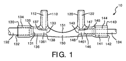
図1は、挿入されたチューブ192及び194を含む例示的な実施態様の呼吸ノーズピース10(呼吸鼻当て)の平面図を例示している。呼吸ノーズピース10は、射出成形によって作製され、例えば、約ショアA15〜ショアA90の範囲内のような、フレキシブルであるよう十分に低いデュロメータを有する、ポリ塩化ビニル、熱可塑性エラストマ、シリコーン、エチレンプロピレンジエンモノマー、又はウレタンのような、ポリマ材料であってよい。
FIG. 1 illustrates a plan view of an exemplary embodiment respiratory nosepiece 10 (respiratory nose pad) that includes inserted
図1に示すような呼吸ノーズピース10は、鼻専用構成であり、第1の側方ポート130に接続される第1の鼻プロング110と、第2の側方ポート140に接続される第2の鼻プロング120と、第1の側方ポート130と第2の側方ポート140との間に延びる輪郭付き架橋区画150とを含む。第1及び第2の鼻プロング110及び120は、患者の鼻孔内に挿入可能であり、患者の快適性のために比較的短い。第1及び第2の鼻プロング110及び120の間のプロング間の間隔は、広範囲の患者集団(patient populations)に適した、約0.25インチ〜0.625インチの範囲内にあってよい。破線によって描く第1の通路112が、第1の(垂直)方向に沿って第1の鼻プロング110を通じて延びる。第1の通路112は、約40,000分の1インチ〜60,000分の1インチの範囲内にあってよい第1の鼻プロング110の長さに沿って実質的に一定の直径を有する。ある例示的な実施態様において、第1の通路112は、それが第1の鼻プロング110を通じて下向きに延びるに応じて、僅かに内向きにテーパ状でよい。
The
図1に示すような第1及び第2の側方ポート130及び140は、両方とも、異なる第1及び第2の直径を有するチューブに接続可能である。第1の側方ポート130は、第1の(垂直)方向に対して直交する第2の(水平)方向に沿って第1の側方ポート130を通じて延びる破線によって描かれる、第2の通路131を含む。第2の通路131は、チューブを挿入可能に受け入れるように構成される第1の端132と、第1の鼻プロング110の第1の通路112と連通する第2の端133とを有する。第2の通路131は、第1の直径を有する第1の端132にある第1の区画134と、第2の直径を有する第2の区画136と、第1及び第2の区画134及び136の間の第1の段部135と、第2の通路131の第2の端133と第2の区画136との間の第2の段部137とを含む。第2の通路131は、第2の直径よりも小さい第3の直径を有する追加的な区画1361を更に含み、追加的な区画1361は、第2の通路131の第2の端133と第2の段部137との間に延びる。
Both first and
第1の段部135は、第1及び第2の区画134及び136の間のテーパ状の直径を有する移行部であり、第2の通路131の内周全体の回りに延在する。第1の段部135は、第2の区画136がチューブ192の過挿入によって閉塞されないよう、第2の区画136内への第1の直径を有するチューブ192のようなチューブの挿入を防止する、硬質ストップ(hard stop)として機能する。第2の段部137は、第2の通路131の第2の端と第2の区画136との間の移行部である。第2の段部137は、追加的な区画1361がチューブ194の過挿入によって閉塞されないよう、第2の通路131の更に内への第2の直径を有するチューブ194のようなチューブの挿入を防止する、硬質ストップとして機能する。第1の段部135と異なり、第2の段部137は、第2の通路131の上方内周に沿ってのみ配置され、第2の通路131内へのチューブの更なる挿入を防止するようチューブ194のような過挿入チューブの端面に対して当接する硬質ストップとして機能する壁部分で構成される。また、第2の通路131の第2の端133は、ガスの流れを第1及び第2の通路112及び131の間に滑らかに方向付け且つガス流中の乱流を最小にするよう、138で球状の形状を有する。
The
破線によって図1に描かれる第3の通路122は、第1の(垂直)方向に沿って第2の鼻プロング120を通じて延びる。第3の通路122は、約40,000分の1インチ〜60,000分の1インチの範囲内にあってよい第2の鼻プロング120の長さに沿って実質的に一定の直径を有する。第3の通路122は、第3の通路122が第2の鼻プロング120を通じて下向きに延びるに応じて、僅かに内向きにテーパ状でよい。
A
第2の側方ポート140は、第2の(水平)方向に沿って第2の側方ポート140を通じて延びる破線によって描く第4の通路141を含む。第4の通路141は、チューブを挿入可能に受け入れるように構成される第1の端142と、第2の鼻プロング120の第3の通路122と連通する第2の端143とを有する。第4の通路141は、第1の直径を有する第1の端142にある第3の区画144と、第2の直径を有する第4の区画146と、第3及び第4の区画144及び146の間の第3の段部145と、第4の通路141の第2の端143と第4の区画146との間の第4の段部147とを含む。第4の通路141は、第2の直径よりも小さな第3の直径を有する追加的な区画1461を更に含み、追加的な区画1461は、第4の通路141の第2の端143と第4の段部147との間に延びる。
The
第3の段部145は、第3及び第4の区画144及び146の間のテーパ状の直径を有する移行部であり、第4の通路141の内周全体に亘って延在する。第3の段部145は、第4の区画146がチューブ192の過挿入によって閉塞されないよう、第4の区画146内への、第1の直径を有するチューブ192のような第1のチューブの挿入を防止する、硬質ストップとして機能する。第4の段部147は、第4の通路141の第2の端143と第4の区画146との間の移行部である。第4の段部147は、追加的な区画1461がチューブ194の過挿入によって閉塞されないよう、第4の通路141の更に内への、第2の直径を有するチューブ194のような第2のチューブの挿入を防止する、硬質ストップとして機能する。第3の段部145と異なり、第4の段部147は、第4の通路141の上方内周に沿って配置されるに過ぎず、第4の通路141内へのチューブの更なる挿入を防止するよう、チューブ194のような挿入されるチューブの端面に対して当接する硬質ストップとして機能する、壁部分で構成される。また、第4の通路141の第2の端143は、第3及び第4の通路122及び141の間のガスの流れを滑らかに方向付け、且つガス流内の乱流を最小にするよう、148で球状の形状をを有する。
The
例示の実施態様において、第1の側方ポート130に接続され且つ図1に示す第2の通路131の第1の区画134内に挿入されるチューブ192は、酸素給送システム(図示せず)に接続される酸素給送チューブであってよい。チューブ192は、第4の通路141の第3の区画144及び第2の通路131の第1の区画の第1の直径に実質的に対応する、約125,000分の1インチの外径を有してよい。他の例示的な実施態様において、図1に示すように第2の側方ポート140に接続され且つ第3の区画144を通じて第4の通路141の第4の区画146内に挿入されるチューブ194は、呼吸ガスモニタリングデバイス(図示せず)に接続される二酸化炭素(CO2)採取チューブであってよい。チューブ194は、第4の通路141の第4の区画146及び第2の通路131の第2の区画136の第2の直径に実質的に対応する、約93,000分の1インチの外径を有してよい。
In the illustrated embodiment, a
例示的な実施態様において、チューブ192は、第1及び第3の段部135及び145に結合されてよく、チューブ194は、接着剤又は溶剤結合によって第2及び第4の段部137及び147に結合されてよい。他の例示的な実施態様において、チューブ192及び194は、チューブ192及び194の外壁から延びる棘付き突起(図示せず)によって第2及び第4の通路131及び141の内壁に取り付けられてよい。
In the exemplary embodiment,
その上、容易に理解されるべきであるように、図1に示すような第1及び第2の側方ポート130及び140は、両方とも、酸素給送チューブであってよいチューブ192又はCO2ガス採取チューブであってよいチューブ194のいずれかを挿入可能に受け入れるように構成される。図1に示すような例示的な実施態様では、第1の側方ポート130内へのチューブ192の挿入及び第2の側方ポート140内へのチューブ194の挿入によって、呼吸ノーズピース10並びにチューブ192及び194を含むガス採取カニューレが提供されてよく、それによって、患者によって吐き出される呼吸CO2ガスが第1の側方ポート130を介して呼吸ガスモニタリングデバイス(図示せず)に給送されてよく、酸素が第2の側方ポート140を介して酸素源(図示せず)から患者に急送されてよい。更なる実施態様では、第1及び第2の側方ポート130及び140の両方の内へのチューブ192の挿入によって、呼吸ノーズピース10及びチューブ192を含むガス採取カニューレが斯様に提供されてよく、そによって、患者によって吐き出される呼吸CO2ガスが第1及び第2の側方ポート130及び140の両方を介して呼吸ガスモニタリングデバイス(図示せず)に給送されてよい。従って、汎用側方ポートとして特徴付けられてよい第1及び第2の側方ポート130及び140を有することによって、図1に示すように構成される呼吸ノーズピース10は、2つの異なる種類の呼吸ノーズピースの機能性を斯様に効率的に組み合わせる。
Moreover, as should be readily understood, the first and
記載されるように、呼吸ノーズピース10は、フレキシブルであるよう十分に低いデュロメータの材料で作製されてよい。第1及び第2の鼻プロング110及び120が鼻孔内に挿入された状態で、呼吸ノーズピース10が患者に取り付けられるとき、図1に示す輪郭付き架橋区画150が、鼻の下に位置付けられて、呼吸ノーズピース10を患者の人中(nasal philtrum)に対して支持してよく、第1及び第2の側方ポート130及び140のいずれかに接続されるチューブ192及び194が、患者の耳の後に掛けられてよい。例示的な実施態様では、第1の(垂直)方向に沿う輪郭付き架橋区画の高さが第1及び第2の鼻プロング110及び120の間の中央地点付近で減少されてよいよう、輪郭付き架橋区画150の頂面が湾曲してよい。断面高さの減少は、呼吸ノーズピース10が取り付けられるときに患者の鼻柱(nasal columella)から離れる方向に延びる、輪郭付き架橋区画150をもたらして、不快な擦傷を回避する。
As described, the breathing
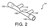
図2は、例示的な実施態様の呼吸ノーズピース10の斜視図を例示している。第1及び第2の鼻プロング110及び120、第1及び第2の側方ポート130及び140、並びに呼吸ノーズピース10の頂面151を含む輪郭付き架橋区画150が、図2に示されている。
FIG. 2 illustrates a perspective view of the
図3は、図1に示す図の下側からの、例示的な実施態様の呼吸ノーズピース10の底面図を例示している。図3に示すような輪郭付き架橋区画150は、頂面151に隣接する側面(側壁)152及び153を含む。図示のような側面152及び153は、輪郭付き架橋区画150の側面152及び153の間の幅が、第1及び第2の鼻プロング110及び120(図示せず)の間の中央地点付近で減少されてよいように、内向きに湾曲させられてよい。幅の減少は、輪郭付き架橋区画150でより大きな可撓性(フレキシビリティ)を可能にし、よって、患者の人中に対するより快適な適合をもたらす。
FIG. 3 illustrates a bottom view of the
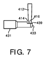
図4は、第1及び第2のピン412及び431を含む、例示的な実施態様の呼吸ノーズピース10の断面図を例示している。第1及び第2のピン412及び431は、図5及び6に関して引き続き記載するように、射出成形プロセス中に成形装置内に挿入されて、第1の鼻プロング110内の第1の通路112及び第1の側方ポート130内の第2の通路131をそれぞれ形成する。第1及び第2のピン412及び431は、鋼又はアルミニウムで作製されてよく、成形材料の射出前に成形装置内に挿入される。よって、図4は、以下のような説明の目的のために、成形材料の射出後であるが、第1及び第2のピン412及び431の収縮前の、呼吸ノーズピース10の断面を示している。
FIG. 4 illustrates a cross-sectional view of an exemplary embodiment
図4に示すような第1のピン412は、実質的に平坦な面416を有する遠位端414を含む、実質的に円筒形である。第1のピン412は、その長さに沿って実質的に一定の直径を有するが、成形材料の射出後により容易に収縮可能であるよう遠位端414に向かって僅かにテーパ状であってよい。第2のピン431は、第1及び第2の端432及び433と、第1の直径を有する第1の区画434と、第2の直径を有する第2の区画436と、成形材料の挿入の直前に、第1及び第2のピン412及び431が成形装置内の完全に挿入された位置にあるときに、第1のピン412の下に整列させられ且つ第1のピン412と直接的に接触する、平坦な側壁部分439を有する、第3の区画4361とを含む。図7の図から理解されるように、第1のピン412が、第2のピン431の側壁部分439と、それらの間に実質的に如何なる間隙又は空間もない状態で接触することにより、射出成形中の呼吸ノーズピース10の第1及び第2の通路112及び131内への樹脂樹脂鋳張り(resin flash)を回避するよう、第1及び第2のピン412及び431は、第1のピン412の遠位端414にある平坦な面416が、第2のピン431の平坦な側壁部分439と直接的に接触させられるよう、構成される。よって、第1及び第2のピン412及び431は、平坦なピンの上にピンがある幾何学的構成(flat pin-on-pin geometry)を有する、それぞれ対向する接触領域を含む。よって、滑らかな移行部が呼吸ノーズピース10の第1及び第2の通路112及び131の間に提供され、ガス流の乱流はない。
The
図4に更に示すように、第2のピン431は、第1及び第2の区画434及び436の間の移行部として段付き部分435を含み、段付き部分435は、呼吸ノーズピース10の第2の通路131内に第1の段部135を形成する。第2のピン431は、第3の区画4361の平坦な側壁部分439と第2の区画436との間の移行部としての壁437を更に含む。壁437は、第2の通路131内に第2の段部137を形成する。第2のピン431の第1及び第2の区画434及び436は、実質的に円筒形であるのに対し、第3の区画4361」は、頂面として平坦な側壁部分439を有する実質的に円筒形の底部分を含む。更に示すように、第2のピン431の第2の(遠位)端433は、第2の通路131内の第2の端133で球状の形状138を相応して形成する、球状の形状の区画438を有し、それは第1及び第2の通路112及び131の間のガス流を滑らかに方向変更するのに役立つと同時に、乱流を最小にする。
As further shown in FIG. 4, the
図4に示す呼吸ノーズピース10は、呼吸ノーズピース10の第3の通路122を形成する第2の鼻プロング120内に第3のピン422と、第4の通路141を形成する第2の側方ポート140内の第4のピン441とを更に含む。第3及び第4のピン422及び441は、第1及び第2のピン412及び431とそれぞれ実質的に同一である。よって、第3及び第4のピン422及び441の詳細な説明は省略する。
The
図5は、例示的な実施態様の第1及び第2の成形片310及び330と、第1のピン412と、第2のピン431と、第3のピン422と、第4のピン441とを含む、成形装置30の斜視図を例示している。初期位置の間の成形装置30が図5に示されており、第1及び第2の成形片310及び330は、互いに離間し、第1乃至第4のピン412、422、431及び441は、収縮位置にある。図6は、例示的な実施態様の成形装置30の斜視図を例示しており、第1及び第2の成形片310及び330は互いに閉塞されている。
FIG. 5 illustrates exemplary embodiment first and second molded
図5に示すような第1の成形片310は、呼吸ノーズピース10の第1の半体を形成する空洞316を含む。第2の成形片330は、呼吸ノーズピース10の第2の半体を形成する追加的な空洞(図示せず)を含む。成形プロセス中、第1及び第2の成形片310及び330は、完全なノーズピース空洞が空洞316及び追加的な空洞(図示せず)によって形成されるよう、互いに接合される。溝311、312、313及び314が、第1の成形片310に形成され、対応する対になる溝331、332、333及び追加的な溝(図示せず)が、第2の成形片330に形成される。図6の閉塞された成形装置30に示すように、第1及び第2の成形片310及び330の対になる溝は、対応するピン挿入孔342、341、343及び対応する第4のピン挿入孔(図示せず)を形成し、第1、第2、第3、及び第4のピン412、431、422、及び441は、閉塞した成形装置30の壁を通じて、対応するピン挿入孔342、341、343、及び対応する第4のピン挿入孔(図示せず)内に挿入され、ノーズピース空洞内に至る。
A first molded
ピンが完全に挿入されると、図5に示す第1のピン412の遠位端414にある平坦な面416が、第2のピン431の第2の端433にある平坦な側壁部分439と直接的に接触し、図7に示すように、それらの間には実質的に如何なる間隙もない。第1及び第2のピン412及び431は、成形装置30内に挿入されると、呼吸ノーズピース10の第1及び第2の通路112及び131をそれぞれ形成し、第1及び第2の通路112及び131は、互いに連通する。同様に、ピンが完全に挿入されるとき、図5に示す第3のピン422の遠位端424にある平坦な面426は、第4のピン441の第2の端433にある平坦な側壁部分449と直接的に接触し、それらの間には実質的に如何なる間隙もない。第3及び第4のピン422及び441は、成形装置30内に挿入されると、呼吸ノーズピース10の第3及び第4の通路122及び141をそれぞれ形成し、第3及び第4の通路122及び141は互いに連通する。
When the pin is fully inserted, the
追加的に、図5に示す場所318のような場所に成形材料を供給するために、射出ポート(図示せず)が第1の成形片310を通じて形成されてよい。場所318でノーズピース空洞に成形材料を供給する射出ポートの位置付けは、図1乃至3に示すような呼吸ノーズピース10の輪郭付き架橋区画150の頂面151並びに/或いは側面152及び153が実質的に滑らかで隆起がなく、呼吸ノーズピース10が患者に取り付けられるときの刺激を最小にすることを保証する。
Additionally, an injection port (not shown) may be formed through the first molded
図7は、形成装置内に完全に挿入され且つ互いに接触するときの例示的な実施態様の第1及び第2のピン412及び431の斜視図を例示している。第1のピン412の遠位端414は、第2のピン431の第2の端433にある平坦な側壁部分439と直接的に接触する平坦な面416を含み、それらの間には実質的に如何なる間隙もなく、呼吸ノーズピース10のそれぞれの第1及び第2の通路112及び131内への樹脂鋳張りを最小にし且つ回避する。
FIG. 7 illustrates a perspective view of the first and
図8は、経口採取ポート260を含む、例示的な実施態様の呼吸ノーズピース20の斜視図を例示している。図8に示すような呼吸ノーズピース20は、図1に関した記載したような、第1の鼻プロング110と、第1の通路112と、第1の側方ポート130と、第2の通路131と、第2の鼻プロング120と、第3の通路122と、第2の側方ポート140とを含み、それらについて、図8を参照した詳細な記載は省略する。第1の鼻プロング110、第1の側方ポート130、第2の鼻プロング120、及び第2の側方ポート140を通じてそれぞれ延びるような、第1乃至第4の通路112、131、122、及び144は、破線によって描いている。
FIG. 8 illustrates a perspective view of the
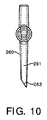
図8に示すような呼吸ノーズピース20は、更に、経口採取ポート260と、架橋区画250内の第5の通路251とを含む。第5の通路251は、第1の側方ポート130内の第2の通路131と連通する第1の端252と、第2の端253とを含む。経口採取ポート260は、第1の(垂直)方向に沿って延びる第6の通路261を含む。第6の通路261は、第5の通路251の第2の端253と連通する第1の端262と、第2の端263とを含む。経口採取ポート260は、呼吸ノーズピース20が患者に取り付けられるときに、第2の端263が患者の口に隣接することがあるように、構成される。図10に示すように、経口採取ポート260の第2の端263は、患者の口に向かって傾斜させられてよい。
The
図8に示すような呼吸ノーズピース20は、鼻呼吸に加えて或いは鼻呼吸の代わりに口呼吸を行いがちな患者のために設計される。例示的な実施態様において、図8に示すような呼吸ノーズピース20の第1の側方ポート130は、第2の直径に実質的に対応する外径を有する図1に示すチューブ194のようなCO2採取チューブを介して、呼吸ガスモニタリングデバイス(図示せず)に接続されてよい。他の例示的な実施態様において、図8に示すような呼吸ノーズピース20の第1の側方ポート130は、第1の直径に実質的に対応する外径を有する図1に示すチューブ192のような酸素給送チューブを介して、酸素供給源(図示せず)に接続されてよい。
A
図9は、例示的な実施態様の経口採取ポート260を含む、呼吸ノーズピース20の斜視図を例示している。呼吸ノーズピース20の第1及び第2の鼻プロング110及び120、第1及び第2の側方ポート130及び140、架橋区画250、及び経口採取ポート260が、図9に示されている。
FIG. 9 illustrates a perspective view of the
図10は、例示的な実施態様の呼吸ノーズピース20の経口採取ポート260の側面図を例示している。図9に示すように、経口採取ポート260の第6の通路261の第2の端263が、(図示されていない、図面の左に配置される)患者の口に向かって傾斜させられる。
FIG. 10 illustrates a side view of the
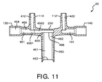
図11は、第5及び第6のピン451及び461を含む、例示的な実施態様の呼吸ノーズピース20の断面図を例示している。第5のピン451は、図8に示す呼吸ノーズピース20の架橋区画250内の第5の通路251及び第2の通路131を形成する射出成形プロセス中に図5及び6に示すような成形装置内に挿入可能である。第6のピン461は、経口採取ポート260内の第6の通路261を形成する射出成形プロセス中に成形装置内に挿入可能である。第5のピン451は、図4に関して記載した第2のピン431と構造が類似するピンであってよく、第2のピン431の第1、第2、及び第3の区画434、436、及び4361にそれぞれ対応する、第1、第2、及び第3の区画454、456、及び4561を含み、第3の区画4561から延びる第4の区画4562を更に含む。第5のピン451は、第4の区画4562に平坦な側壁部分459を含んでよい。第6のピン461は、第2の(遠位)端462に平坦な端面466を有してよい。対応する成形装置内に完全に挿入されると、第6のピン461の平坦な端面466は、第5のピン451の第4の区画4562にある平坦な側壁部分459と直接的に接触させられ、それらの間には間隙がなく、呼吸ノーズピース20の第5及び第6の通路251及び261内への樹脂鋳張りを最小にし且つ回避する。
FIG. 11 illustrates a cross-sectional view of the
変形として、例えば、射出成形ツールフレーム内で多数回反復され、各空洞/コアの組み合わせがその独自のセットのピンを有する、図5に示すような空洞316を有する第1及び第2の成形片310及び330を含む、多空洞ツールが提供されてよい。射出成形ツールの全体的な機構は、各空洞/コアのセットのためにピンを相応して作動させる。 As a variation, for example, first and second molded pieces having cavities 316 as shown in FIG. 5, repeated many times in an injection molding tool frame, each cavity / core combination having its own set of pins. A multi-cavity tool including 310 and 330 may be provided. The overall mechanism of the injection molding tool actuates the pins correspondingly for each cavity / core set.
幾つかの発明的な実施態様をここに記載し且つ例示したが、当業者は、ここに記載する利点の1つ又はそれよりも多く及び/又は結果を取得し、且つ/或いは機能を遂行する、様々な多の手段及び/又は構造を直ちに予見するであろう。そのような変形及び/又は修正の各々は、ここに記載する発明的な実施態様の範囲内にあるものと見做される。より一般的には、当業者は、ここに記載する全てのパラメータ、寸法、材料、及び構成が、例示的であることを意図すること、並びに、実際のパラメータ、寸法、材料、及び/又は構成が、発明的な教示を用いる特定の用途又は複数の用途に依存することを直ちに理解するであろう。従って、前記の実施態様は、一例として提示されているに過ぎないこと、並びに、付属の請求項及びそれらの均等物の範囲内で、発明的な実施態様は、具体的に記載され且つ請求されるのと異なって実施されてよいことが理解されるべきである。本開示の発明的な実施態様は、ここに記載する各個別の構成、システム、物品、材料、キット、及び/又は方法に向けられている。加えて、2つ又はそれよりも多くのそのような構成、システム、物品、材料、キット、及び/又は方法のあらゆる組み合わせは、そのような構成、システム、物品、材料、キット、及び/又は方法が相互に矛盾しないならば、本開示の発明的な範囲内に含められる。 Although several inventive embodiments have been described and illustrated herein, one of ordinary skill in the art will obtain and / or perform a function and / or result in one or more of the advantages described herein. A variety of means and / or structures will immediately be foreseen. Each such variation and / or modification is considered to be within the scope of the inventive embodiments described herein. More generally, those skilled in the art will appreciate that all parameters, dimensions, materials, and configurations described herein are intended to be exemplary and that actual parameters, dimensions, materials, and / or configurations Will immediately depend on the particular application or applications using the inventive teachings. Accordingly, the foregoing embodiments have been presented by way of example only, and within the scope of the appended claims and their equivalents, the inventive embodiments are specifically described and claimed. It should be understood that it may be implemented differently. Inventive embodiments of the present disclosure are directed to each individual configuration, system, article, material, kit, and / or method described herein. In addition, any combination of two or more such configurations, systems, articles, materials, kits, and / or methods may be combined into such configurations, systems, articles, materials, kits, and / or methods. Are consistent with each other, are included within the inventive scope of the present disclosure.
ここにおいて定められ且つ用いられる全ての定義は、辞書的な定義、参照として援用される参考文献中の定義、及び/又は定義づけられる用語の通常の意味を支配するものと理解されるべきである。 All definitions set forth and used herein should be understood to govern the lexical definition, the definition in the reference incorporated by reference, and / or the ordinary meaning of the term being defined. .
ここにおいて明細書中で並びに請求項中で用いられるとき、不定冠詞は、明らかに逆のことが示されない限り、「少なくとも1つ」を意味するものと理解されるべきである。 As used herein in the specification and in the claims, the indefinite article should be understood to mean "at least one" unless the contrary is clearly indicated.
ここにおいて明細書中で並びに請求項中で用いられるとき、「及び/又は」という成句は、そのように結合される要素の「いずれか又は両方」、即ち、一部の場合には結合的に存在するが、他の場合には非結合的に存在する要素、を意味するものと理解されるべきである。「及び/又は」と共に列挙される多数の要素は、同じように、即ち、要素の「1つ又はそれよりも多く」がそのように結合されるものと解釈されるべきである。「及び/又は」節によって具体的に特定される要素以外の他の要素が、それらの具体的に特定される要素に関係しようが関係しまいが、任意的に存在してよい。よって、非限定的な例として、「A及び/又はB」についての言及は、「含む」のような開端(オープンエンド)言語と共に用いられるとき、1つの実施態様において、(B以外の要素を任意的に含む)Aのみを指し、他の実施態様において、(A以外の要素を任意的に含む)Bのみを指し、更に他の実施態様において、(他の要素を任意的に含む)A及びBの両方を指す等である。 As used herein in the specification and in the claims, the phrase “and / or” refers to “either or both” of the elements so conjoined, ie, in some cases conjointly. It should be understood to mean an element that exists but is otherwise non-bonded. Multiple elements listed with “and / or” should be construed in the same way, ie, “one or more” of the elements are so combined. There may optionally be other elements other than those specifically specified by the “and / or” clause, whether or not they relate to those specifically specified elements. Thus, as a non-limiting example, a reference to “A and / or B” when used with an open-ended language such as “includes”, in one embodiment, includes elements other than B (Optionally) refers only to A, in other embodiments, refers only to B (optionally includes elements other than A), and in yet other embodiments, refers to A (optionally includes other elements) And both B and the like.
ここにおいて明細書中で並びに請求項中で用いられるとき、「又は」は、上で定義した「及び/又は」と同じ意味を有するものと理解されるべきである。例えば、あるリスト中の品目を分離するとき、「又は」又は「及び/又は」は、内包的である、即ち、多数の要素又は要素のリストの少なくとも1つを含むが、1つよりも多くも含み、任意的に、リストされていない追加的な品目を含むものと解釈されなければならない。「〜のうちの少なくとも1つ」又は「〜のうちの正に1つ」のような、明らかに逆のことを示す用語、或いは、請求項において用いられるときの「〜成る」のみが、多数の要素又は要素のリストのうちの正に1つの要素が含まれることを指す。一般的に、ここにおいて用いられるとき、「又は」という用語は、「〜のいずれか」、「〜のうちの1つ」、「〜の1つのみ」、又は「〜の正に1つ」のような、排他性の用語によって先行されるとき、排他的な代替(即ち、〜のいずれか一方であるが、両方ではない)としてのみ解釈されるべきである。請求項において用いられるとき、「本質的に〜成る」は、特許法の分野において用いられるときのその通常の意味を有する。 As used herein in the specification and in the claims, “or” should be understood to have the same meaning as “and / or” as defined above. For example, when separating items in a list, “or” or “and / or” is inclusive, ie includes at least one of a number of elements or lists of elements, but more than one. And, optionally, should be construed to include additional items not listed. There are many terms that clearly indicate the opposite, such as “at least one of” or “exactly one of” or “consisting of” when used in the claims. Means that exactly one element of the element or the list of elements is included. In general, as used herein, the term “or” means “any of”, “one of”, “only one of”, or “just one of”. Should be construed only as an exclusive alternative (i.e., but not both) when preceded by an exclusive term such as. As used in the claims, “consisting essentially of” has its ordinary meaning when used in the field of patent law.
ここにおいて明細書中で並びに請求項中で用いられるとき、1つ又はそれよりも多くの要素のリストへの言及における「少なくとも1つ」という成句は、要素のそのリスト中の要素のうちの任意の1つ又はそれよりも多くから選択される少なくとも1つを意味するが、要素のそのリスト中に具体的に列挙されるありとあらゆる要素の少なくとも1つを必ずしも含まず、要素のそのリスト中の要素の任意の組み合わせを排除しないものと理解されるべきである。この定義は、具体的に特定される要素に関係しようが関係しまいが、「少なくとも1つ」という成句が言及する要素のリスト中に具体的に特定される要素以外の要素が任意的に存在してよいことも許容する。よって、非限定的な例として、「A及びBの少なくとも1つ」(或いは、均等的に「A又はBの少なくとも1つ」、或いは、均等的に、「A及び/又はBの少なくとも1つ」)は、1つの実施態様において、Bが存在しない(そして、任意的に、B以外の要素を含む)、1つよりも多くを任意的に含む、少なくとも1つのAを意味し、他の実施態様において、Aが存在しない(そして、任意的に、A以外の要素を含む)1つよりも多くを任意的に含む、少なくとも1つのBを意味し、更に他の実施態様において、任意的に1つよりも多くを含む、少なくとも1つのA、及び、任意的に少なくとも1つよりも多くを含み、(そして、任意的に、他の要素を含む)少なくとも1つのB等を意味する。 As used herein in the specification and in the claims, the phrase “at least one” in referring to a list of one or more elements is any of the elements in that list of elements. Means at least one selected from one or more of the following, but does not necessarily include at least one of every and every element specifically listed in that list of elements, and elements in that list of elements It should be understood that any combination of the above is not excluded. This definition may or may not relate to a specifically identified element, but there is an optional element other than the specifically identified element in the list of elements to which the phrase “at least one” refers. It is permissible. Thus, as a non-limiting example, “at least one of A and B” (or equivalently “at least one of A or B” or equivalently “at least one of A and / or B” ") Means, in one embodiment, at least one A, optionally containing more than one, wherein B is absent (and optionally includes elements other than B) In an embodiment, A is absent (and optionally includes elements other than A) means at least one B, optionally including more than one, and in yet other embodiments, optional Means at least one A containing more than one, and optionally at least one B containing more than one (and optionally other elements).
逆のことを明らかに示さない限り、1つのステップ又は行為よりも多くを含む、ここに請求されるあらゆる方法において、方法のステップ又は行為の順序は、方法のステップ又は行為が引用される順序に必ずしも限定されないことが理解されるべきである。 Unless expressly indicated to the contrary, in any method claimed herein that includes more than one step or action, the order of the method steps or actions is in the order in which the method steps or actions are cited. It should be understood that it is not necessarily limited.
請求項において、並びに、上記明細書において、「含む」、「包含する」、「支持する」、「有する」、「収容する」、「包含する」、「保持する」、「〜で構成される」、及び同等物のような、全ての移行句は、開端(オープンエンド)である、即ち、非限定的に含むことを意味するものと理解されるべきである。「〜成る」及び「本質的に〜成る」という移行句のみが、米国特許審査便覧のセクション211に示されるような、閉端的(closed)又は半閉端的(semi-closed)な移行句である。 In the claims as well as in the above specification, “comprising”, “including”, “supporting”, “having”, “containing”, “including”, “holding”, “consisting of” All transitional phrases such as “and the like” should be understood to mean open-ended, ie, including but not limited to. Only the transitional phrases “consisting of” and “consisting essentially of” are closed or semi-closed transitional phrases as shown in Section 211 of the US Patent Examination Manual. .
Claims (12)
異なる第1の直径及び第2の直径を有するチューブに接続可能な第1の側方ポートとを含み、
該第1の側方ポートは、前記第1の方向に対して直交する第2の方向に沿って延びる第2の通路を含み、該第2の通路は、前記チューブを挿入可能に受け入れるように構成される第1の端を有し、且つ、該第1の通路と連通する第2の端を有し、
前記第2の通路は、前記第1の直径を有する前記第1の端にある第1の区画と、前記第2の直径を有する第2の区画と、前記第1及び第2の区画の間の第1の段部と、前記第2の通路の前記第2の端と前記第2の区画との間の第2の段部とを含み、前記第1の段部は、前記第2の区画の内への、前記第1の直径を有する第1のチューブの挿入を防止するように構成され、前記第2の段部は、前記第2の通路の更に内への、前記第2の直径を有する第2のチューブの挿入を防止するように構成され、
前記第2の段部は、前記第2の通路の上方内周に沿ってのみ配置され、前記第2の通路内への挿入されたチューブの更なる挿入を防止するように前記チューブの端面に当接する硬質ストップとして機能する壁部分で構成される、
呼吸ノーズピース。 A first nasal prong configured to be insertable into a patient's nostril, wherein the first passage extends through the first nasal prong in a first direction;
A first side port connectable to tubes having different first diameters and second diameters;
The first side port includes a second passage extending along a second direction orthogonal to the first direction, the second passage receiving the tube in an insertable manner. Having a first end configured and having a second end in communication with the first passage;
The second passage is between a first section at the first end having the first diameter, a second section having the second diameter, and between the first and second sections. A first step portion, and a second step portion between the second end of the second passage and the second section, the first step portion being the second step portion. Configured to prevent insertion of a first tube having the first diameter into a compartment, wherein the second step is further into the second passage. Configured to prevent insertion of a second tube having a diameter;
The second step portion is disposed only along the upper inner periphery of the second passage, and is provided on an end surface of the tube so as to prevent further insertion of the inserted tube into the second passage. Consists of a wall part that functions as a hard stop to abut,
Breathing nosepiece.
前記チューブに接続可能な第2の側方ポートとを含み、該第2の側方ポートは、前記第2の方向に沿って延びる第4の通路を含み、該第4の通路は、前記チューブを挿入可能に受け入れるように構成される第1の端と、前記第3の通路と連通する第2の端とを有し、
前記第4の通路は、前記第1の直径を有する前記第1の端にある第3の区画と、前記第2の直径を有する第4の区画と、前記第3及び第4の区画の間の第3の段部と、前記第4の通路の前記第2の端と前記第4の区画との間の第4の段部とを含み、前記第3の段部は、前記第3の区画の内への、前記第1のチューブの挿入を防止するように構成され、前記第4の段部は、前記第4の通路の更に内への、前記第2のチューブの挿入を防止するように構成される、
請求項1に記載の呼吸ノーズピース。 A second nasal prong configured to be insertable into another nasal cavity of the patient, wherein the third passage extends through the second nasal prong along the first direction. With prongs,
A second side port connectable to the tube, the second side port including a fourth passage extending along the second direction, wherein the fourth passage is the tube. Having a first end configured to be insertably received and a second end in communication with the third passageway,
The fourth passageway includes a third section at the first end having the first diameter, a fourth section having the second diameter, and between the third and fourth sections. A third step portion and a fourth step portion between the second end of the fourth passage and the fourth section, wherein the third step portion is the third step portion. Configured to prevent insertion of the first tube into a compartment, and the fourth step prevents insertion of the second tube further into the fourth passage. Configured as
The respiratory nosepiece according to claim 1.
前記第1の方向に沿って延びる第6の通路を含む経口採取ポートとを更に含み、前記第6の通路は、前記第5の通路の前記第2の端と連通する第1の端を有し、患者の口に隣接するように構成される第2の端を有する、
請求項3に記載の呼吸ノーズピース。 A fifth passage in the bridging section having a first end in communication with the second end of the fourth passage and having a second end;
An oral collection port including a sixth passage extending along the first direction, the sixth passage having a first end in communication with the second end of the fifth passage. And having a second end configured to be adjacent to the patient's mouth,
The respiratory nosepiece according to claim 3.
第1の通路を有する第1の側方ポートであって、前記第1の通路は、異なる第1及び第2の直径を有するチューブを挿入可能に受け入れるように構成される第1の端と、前記第1の鼻プロングと連通する第2の端とを有する、第1の側方ポートと、
第2の通路を有する第2の側方ポートであって、前記第2の通路は、前記チューブを挿入可能に受け入れるように構成される第1の端と、前記第2の鼻プロングと連通する第2の端とを有する、第2の側方ポートとを含み、
前記第1及び第2の通路の各々は、
前記第2の直径を有する第2の区画が後続する前記第1の端で前記第1の直径を有する第1の区画であって、前記第1の直径は、前記第2の直径よりも大きい、第1の区画と、
前記第2の区画に続く第3の区画であって、前記第2の直径よりも小さな第3の直径を有する、第3の区画と、
前記第1及び第2の区画の間の第1の段部、並びに前記第2及び第3の区画の間の第2の段部とを含み、
前記第1の段部は、前記第2の区画の内への、前記第1の直径を有する第1のチューブの挿入を防止するように構成され、前記第2の段部は、前記第2の通路の更に内への、前記第2の直径を有する第2のチューブの挿入を防止するように構成され、
前記第2の段部は、前記第2の通路の上方内周に沿ってのみ配置され、前記第2の通路内への挿入されたチューブの更なる挿入を防止するように前記チューブの端面に当接する硬質ストップとして機能する壁部分で構成される、
呼吸ノーズピース。 First and second nasal prongs configured to be insertable into a patient's nostril;
A first side port having a first passage, wherein the first passage is configured to removably receive tubes having different first and second diameters; A first side port having a second end in communication with the first nasal prong;
A second side port having a second passage, wherein the second passage is in communication with the first end configured to insertably receive the tube and the second nasal prong. A second side port having a second end,
Each of the first and second passages is
A first section having the first diameter at the first end followed by a second section having the second diameter, the first diameter being greater than the second diameter; The first compartment;
A third section following the second section, the third section having a third diameter smaller than the second diameter;
A first step between the first and second compartments, and a second step between the second and third compartments,
The first step is configured to prevent insertion of a first tube having the first diameter into the second compartment, and the second step is the second step. Configured to prevent the insertion of the second tube having the second diameter into the further passage of
The second step portion is disposed only along the upper inner periphery of the second passage, and is provided on an end surface of the tube so as to prevent further insertion of the inserted tube into the second passage. Consists of a wall part that functions as a hard stop to abut,
Breathing nosepiece.
該架橋区画内の第3の通路であって、前記第1の通路の前記第2の端と連通する第1の端を有し、且つ、第2の端を有する、第3の通路と、
前記第1及び第2の鼻プロングと同じ方向に沿って延びる経口採取ポートであって、前記第3の通路の前記第2の端と連通する第1の端を有し、且つ、患者の口に隣接するように構成される第2の端を有する、第4の通路を含む、経口採取ポートとを更に含む、
請求項11に記載の呼吸ノーズピース。 A bridging compartment extending between the first and second side ports and configured to support the respiratory nosepiece to a patient;
A third passage in the bridging section, having a first end in communication with the second end of the first passage and having a second end;
An oral collection port extending along the same direction as the first and second nasal prongs, having a first end in communication with the second end of the third passage, and a mouth of the patient An oral collection port, including a fourth passage, having a second end configured to be adjacent to
The respiratory nosepiece according to claim 11.
Applications Claiming Priority (3)
| Application Number | Priority Date | Filing Date | Title |
|---|---|---|---|
| US201461938729P | 2014-02-12 | 2014-02-12 | |
| US61/938,729 | 2014-02-12 | ||
| PCT/IB2015/051045 WO2015121815A1 (en) | 2014-02-12 | 2015-02-12 | Flexible low deadspace respiratory nosepiece for gas sampling cannulae and method of manufacturing respiratory nosepiece |
Publications (3)
| Publication Number | Publication Date |
|---|---|
| JP2017506949A JP2017506949A (en) | 2017-03-16 |
| JP2017506949A5 JP2017506949A5 (en) | 2018-07-12 |
| JP6445576B2 true JP6445576B2 (en) | 2018-12-26 |
Family
ID=52595380
Family Applications (1)
| Application Number | Title | Priority Date | Filing Date |
|---|---|---|---|
| JP2016550746A Active JP6445576B2 (en) | 2014-02-12 | 2015-02-12 | Flexible low dead space respiratory nosepiece for gas sampling cannula and method of manufacturing respiratory nosepiece |
Country Status (6)
| Country | Link |
|---|---|
| US (1) | US10471228B2 (en) |
| EP (1) | EP3104924B1 (en) |
| JP (1) | JP6445576B2 (en) |
| CN (1) | CN105992560B (en) |
| MX (1) | MX2016010311A (en) |
| WO (1) | WO2015121815A1 (en) |
Families Citing this family (15)
| Publication number | Priority date | Publication date | Assignee | Title |
|---|---|---|---|---|
| AU2016209104B2 (en) * | 2015-01-23 | 2020-04-30 | Masimo Sweden Ab | Nasal/oral cannula system and manufacturing |
| CN211798112U (en) | 2015-06-30 | 2020-10-30 | 蒸汽热能公司 | Nasal cannula and respiratory therapy system |
| US10220174B2 (en) * | 2016-02-17 | 2019-03-05 | Christine M. Huerta | Septi-cannula |
| AU2017290742B2 (en) | 2016-06-30 | 2021-07-29 | Vapotherm, Inc. | Cannula device for high flow therapy |
| CN109906097B (en) * | 2016-08-31 | 2022-01-14 | 费雪派克医疗保健有限公司 | Patient interface, system and method |
| DE102017004224A1 (en) * | 2016-12-13 | 2018-11-08 | Drägerwerk AG & Co. KGaA | Nasal cannula for high-flow ventilation |
| USD859646S1 (en) * | 2017-01-23 | 2019-09-10 | Koninklijke Philips N.V. | Nasal cannula |
| USD873410S1 (en) * | 2017-01-24 | 2020-01-21 | Koninklijke Philips N.V. | Nasal cannula with oral scoop |
| EP3678721A1 (en) * | 2017-09-08 | 2020-07-15 | Vapotherm, Inc. | Birfurcated cannula device |
| USD917042S1 (en) * | 2017-12-29 | 2021-04-20 | Koninklijke Philips N.V. | Nasal cannula |
| AU2020302871A1 (en) | 2019-06-28 | 2022-01-27 | Vapotherm, Inc. | Variable geometry cannula |
| US11607064B2 (en) | 2019-08-06 | 2023-03-21 | Dart Industries Inc. | Reusable drinking straw |
| EP4353288A2 (en) | 2019-09-26 | 2024-04-17 | Vapotherm, Inc. | Internal cannula mounted nebulizer |
| USD957622S1 (en) * | 2019-10-16 | 2022-07-12 | Aires Medical LLC | Nasal cannula |
| CN214050088U (en) * | 2020-10-30 | 2021-08-27 | 北京怡和嘉业医疗科技股份有限公司 | Nasal plug for nasal oxygen catheter, nasal oxygen catheter and ventilation treatment equipment |
Family Cites Families (21)
| Publication number | Priority date | Publication date | Assignee | Title |
|---|---|---|---|---|
| DE2845346B2 (en) | 1978-10-18 | 1980-11-27 | Sterimed Gesellschaft Fuer Medizinischen Bedarf Mbh, 6600 Saarbruecken | Connecting sleeve |
| US4989599A (en) * | 1989-01-26 | 1991-02-05 | Puritan-Bennett Corporation | Dual lumen cannula |
| JPH05505119A (en) | 1991-01-29 | 1993-08-05 | ピューリタン―ベネット コーポレイション | double lumen cannula |
| DK171592B1 (en) * | 1993-12-21 | 1997-02-17 | Maersk Medical As | Device for supplying oxygen and / or other gases to a patient |
| CN2231113Y (en) | 1995-02-07 | 1996-07-17 | 宋进省 | Tracheal catheter through nasal cavity |
| CA2370995C (en) | 2001-09-13 | 2010-08-17 | Fisher & Paykel Healthcare Limited | Breathing assistance apparatus |
| US20040182397A1 (en) * | 2003-03-21 | 2004-09-23 | Innomed Technologies, Inc. | Nasal interface including ventilation insert |
| US7472707B2 (en) * | 2003-08-06 | 2009-01-06 | Innomed Technologies, Inc. | Nasal interface and system including ventilation insert |
| US7970631B2 (en) * | 2004-08-31 | 2011-06-28 | Ethicon Endo-Surgery, Inc. | Medical effector system |
| US7383839B2 (en) * | 2004-11-22 | 2008-06-10 | Oridion Medical (1987) Ltd. | Oral nasal cannula |
| JP2007229207A (en) * | 2006-03-01 | 2007-09-13 | Saitama Univ | Nasal cpap element |
| US20080105318A1 (en) * | 2006-10-11 | 2008-05-08 | Leone James E | Turbulence Minimizing Device for Multi-Lumen Fluid Infusing Systems and Method for Minimizing Turbulence in Such Systems |
| US8371304B2 (en) | 2007-12-28 | 2013-02-12 | Carefusion | Continuous positive airway pressure device and method |
| CN101977648A (en) * | 2008-01-25 | 2011-02-16 | 索尔特实验室 | Respiratory therapy system including a nasal cannula assembly |
| US8707954B2 (en) * | 2008-10-09 | 2014-04-29 | Daniel A. McCarthy | Air/oxygen supply system and method |
| WO2010115166A1 (en) * | 2009-04-02 | 2010-10-07 | Breathe Technologies, Inc. | Methods, systems and devices for non-invasive open ventilation with gas delivery nozzles in free space |
| JP3157855U (en) * | 2009-12-17 | 2010-03-04 | アトムメディカル株式会社 | Oxygen supply equipment |
| US8939152B2 (en) | 2010-09-30 | 2015-01-27 | Breathe Technologies, Inc. | Methods, systems and devices for humidifying a respiratory tract |
| US20140005565A1 (en) * | 2012-06-29 | 2014-01-02 | Steven J. Derrick | Oral/nasal cannula manifold |
| EP2928532A4 (en) * | 2012-12-07 | 2016-06-29 | Parion Sciences Inc | Nasal cannula for delivery of aerosolized medicaments |
| US10716908B2 (en) * | 2013-08-06 | 2020-07-21 | Fisher & Paykel Healthcare Limited | Infant CPAP device, interface and system |
-
2015
- 2015-02-12 MX MX2016010311A patent/MX2016010311A/en unknown
- 2015-02-12 WO PCT/IB2015/051045 patent/WO2015121815A1/en active Application Filing
- 2015-02-12 CN CN201580008412.2A patent/CN105992560B/en active Active
- 2015-02-12 US US15/118,644 patent/US10471228B2/en active Active
- 2015-02-12 EP EP15706942.8A patent/EP3104924B1/en active Active
- 2015-02-12 JP JP2016550746A patent/JP6445576B2/en active Active
Also Published As
| Publication number | Publication date |
|---|---|
| EP3104924A1 (en) | 2016-12-21 |
| US20170049986A1 (en) | 2017-02-23 |
| CN105992560A (en) | 2016-10-05 |
| CN105992560B (en) | 2019-06-04 |
| US10471228B2 (en) | 2019-11-12 |
| JP2017506949A (en) | 2017-03-16 |
| EP3104924B1 (en) | 2018-08-29 |
| MX2016010311A (en) | 2016-10-17 |
| WO2015121815A1 (en) | 2015-08-20 |
Similar Documents
| Publication | Publication Date | Title |
|---|---|---|
| JP6445576B2 (en) | Flexible low dead space respiratory nosepiece for gas sampling cannula and method of manufacturing respiratory nosepiece | |
| CN102655738B (en) | Mouthpiece-vented teat cup inflation | |
| JP4806016B2 (en) | Nose and mouth cannula having two functions and manufacturing method thereof | |
| JP4703572B2 (en) | Naso-oral cannula supply, sample collection and / or detector | |
| JP4170094B2 (en) | Method for manufacturing nasal and mouth cannula respiratory detection device | |
| CN101918063B (en) | Tubes and their manufacture | |
| JP2017506949A5 (en) | ||
| US20070296125A1 (en) | Thin cuff for use with medical tubing and method and apparatus for making the same | |
| US20080078398A1 (en) | Methods of forming a laryngeal mask | |
| US20220280739A1 (en) | Respiratory interface device and method of manufacturing a sealing member for a respiratory interface device | |
| US20110290254A1 (en) | Tracheal tube with connector insert | |
| US20120247469A1 (en) | Infant pacifier for oxygen delivery | |
| US6533983B2 (en) | Method to produce nasal and oral cannula apnea detection devices | |
| US20170136207A1 (en) | Catheter, catheter production mold, catheter production method | |
| JP2005270319A (en) | Tracheotomy tube | |
| CN104363944B (en) | Tracheostomy tube | |
| US20180185601A1 (en) | Sensor adaptor, apparatus, and method for monitoring end-tidal carbon dioxide | |
| CA2888285A1 (en) | Tracheostomy tube with cannula connector | |
| JP6456309B2 (en) | Milker liner and breast interface | |
| CN107614043B (en) | Manufacturing method of trachea cannula and trachea cannula | |
| KR101544350B1 (en) | Endo-tracheal dual tube | |
| US20140316357A1 (en) | Noise-suppressing, suction probe apparatus and method | |
| CN219501764U (en) | Nasal oxygen cannula |
Legal Events
| Date | Code | Title | Description |
|---|---|---|---|
| A621 | Written request for application examination |
Free format text: JAPANESE INTERMEDIATE CODE: A621 Effective date: 20180208 |
|
| A521 | Request for written amendment filed |
Free format text: JAPANESE INTERMEDIATE CODE: A523 Effective date: 20180604 |
|
| A871 | Explanation of circumstances concerning accelerated examination |
Free format text: JAPANESE INTERMEDIATE CODE: A871 Effective date: 20180604 |
|
| A975 | Report on accelerated examination |
Free format text: JAPANESE INTERMEDIATE CODE: A971005 Effective date: 20180626 |
|
| A131 | Notification of reasons for refusal |
Free format text: JAPANESE INTERMEDIATE CODE: A131 Effective date: 20180703 |
|
| A521 | Request for written amendment filed |
Free format text: JAPANESE INTERMEDIATE CODE: A523 Effective date: 20180925 |
|
| TRDD | Decision of grant or rejection written | ||
| A01 | Written decision to grant a patent or to grant a registration (utility model) |
Free format text: JAPANESE INTERMEDIATE CODE: A01 Effective date: 20181106 |
|
| A61 | First payment of annual fees (during grant procedure) |
Free format text: JAPANESE INTERMEDIATE CODE: A61 Effective date: 20181129 |
|
| R150 | Certificate of patent or registration of utility model |
Ref document number: 6445576 Country of ref document: JP Free format text: JAPANESE INTERMEDIATE CODE: R150 |
|
| R250 | Receipt of annual fees |
Free format text: JAPANESE INTERMEDIATE CODE: R250 |
|
| R250 | Receipt of annual fees |
Free format text: JAPANESE INTERMEDIATE CODE: R250 |
|
| R250 | Receipt of annual fees |
Free format text: JAPANESE INTERMEDIATE CODE: R250 |