JP6445314B2 - Powder processing equipment and powder processing equipment - Google Patents
Powder processing equipment and powder processing equipment Download PDFInfo
- Publication number
- JP6445314B2 JP6445314B2 JP2014252179A JP2014252179A JP6445314B2 JP 6445314 B2 JP6445314 B2 JP 6445314B2 JP 2014252179 A JP2014252179 A JP 2014252179A JP 2014252179 A JP2014252179 A JP 2014252179A JP 6445314 B2 JP6445314 B2 JP 6445314B2
- Authority
- JP
- Japan
- Prior art keywords
- powder
- processing
- cyclone
- gas
- container
- Prior art date
- Legal status (The legal status is an assumption and is not a legal conclusion. Google has not performed a legal analysis and makes no representation as to the accuracy of the status listed.)
- Active
Links
- 238000009700 powder processing Methods 0.000 title claims description 130
- 239000000843 powder Substances 0.000 claims description 345
- 239000002994 raw material Substances 0.000 claims description 53
- 230000002093 peripheral effect Effects 0.000 claims description 43
- 239000000203 mixture Substances 0.000 claims description 38
- 238000011084 recovery Methods 0.000 claims description 24
- 238000009825 accumulation Methods 0.000 claims description 20
- 238000005192 partition Methods 0.000 claims description 16
- 238000007599 discharging Methods 0.000 claims description 10
- JTJMJGYZQZDUJJ-UHFFFAOYSA-N phencyclidine Chemical class C1CCCCN1C1(C=2C=CC=CC=2)CCCCC1 JTJMJGYZQZDUJJ-UHFFFAOYSA-N 0.000 claims description 7
- 238000000638 solvent extraction Methods 0.000 claims 1
- 238000001816 cooling Methods 0.000 description 19
- 230000000694 effects Effects 0.000 description 16
- 238000000034 method Methods 0.000 description 16
- 230000008569 process Effects 0.000 description 14
- 238000010586 diagram Methods 0.000 description 8
- 239000002131 composite material Substances 0.000 description 7
- 239000000463 material Substances 0.000 description 7
- 239000002245 particle Substances 0.000 description 7
- 238000011144 upstream manufacturing Methods 0.000 description 6
- 238000004891 communication Methods 0.000 description 5
- 238000009499 grossing Methods 0.000 description 4
- 238000010438 heat treatment Methods 0.000 description 4
- 238000010298 pulverizing process Methods 0.000 description 4
- OKTJSMMVPCPJKN-UHFFFAOYSA-N Carbon Chemical compound [C] OKTJSMMVPCPJKN-UHFFFAOYSA-N 0.000 description 3
- 229910052751 metal Inorganic materials 0.000 description 3
- 239000002184 metal Substances 0.000 description 3
- VYZAMTAEIAYCRO-UHFFFAOYSA-N Chromium Chemical compound [Cr] VYZAMTAEIAYCRO-UHFFFAOYSA-N 0.000 description 2
- 239000000919 ceramic Substances 0.000 description 2
- 238000005516 engineering process Methods 0.000 description 2
- 239000010439 graphite Substances 0.000 description 2
- 229910002804 graphite Inorganic materials 0.000 description 2
- 230000001788 irregular Effects 0.000 description 2
- 230000014759 maintenance of location Effects 0.000 description 2
- 238000002844 melting Methods 0.000 description 2
- 230000008018 melting Effects 0.000 description 2
- 238000007747 plating Methods 0.000 description 2
- 230000000717 retained effect Effects 0.000 description 2
- 238000000926 separation method Methods 0.000 description 2
- 239000004677 Nylon Substances 0.000 description 1
- GWEVSGVZZGPLCZ-UHFFFAOYSA-N Titan oxide Chemical compound O=[Ti]=O GWEVSGVZZGPLCZ-UHFFFAOYSA-N 0.000 description 1
- 230000001174 ascending effect Effects 0.000 description 1
- 230000008901 benefit Effects 0.000 description 1
- 229910052799 carbon Inorganic materials 0.000 description 1
- 238000013329 compounding Methods 0.000 description 1
- 239000000110 cooling liquid Substances 0.000 description 1
- 238000007791 dehumidification Methods 0.000 description 1
- 229910052500 inorganic mineral Inorganic materials 0.000 description 1
- 239000007788 liquid Substances 0.000 description 1
- 239000012567 medical material Substances 0.000 description 1
- 239000011707 mineral Substances 0.000 description 1
- 230000004048 modification Effects 0.000 description 1
- 238000012986 modification Methods 0.000 description 1
- 229920001778 nylon Polymers 0.000 description 1
- 230000003287 optical effect Effects 0.000 description 1
- 230000000704 physical effect Effects 0.000 description 1
- 239000004033 plastic Substances 0.000 description 1
- 239000002861 polymer material Substances 0.000 description 1
- 239000011347 resin Substances 0.000 description 1
- 229920005989 resin Polymers 0.000 description 1
- 238000009751 slip forming Methods 0.000 description 1
- 238000005507 spraying Methods 0.000 description 1
- 238000007751 thermal spraying Methods 0.000 description 1
- OGIDPMRJRNCKJF-UHFFFAOYSA-N titanium oxide Inorganic materials [Ti]=O OGIDPMRJRNCKJF-UHFFFAOYSA-N 0.000 description 1
Images


Description
本発明は、粒子状の粉体を球形化する、粉体の表面を平滑化する、粉体を粉砕する、または2種類以上の粉体を混合して複合化する粉体処理装置および紛体処理設備に係り、とりわけ、粉体の処理時間を延ばして処理効果を向上させるとともに粉体の処理を均一化させることができる粉体処理装置および粉体処理設備に関する。 The present invention relates to a powder processing apparatus and powder processing that spheroidizes a particulate powder, smoothes the surface of the powder, pulverizes the powder, or mixes two or more types of powder to form a composite. More particularly, the present invention relates to a powder processing apparatus and a powder processing facility capable of extending the processing time of powder to improve the processing effect and uniformize the processing of the powder.
最近、電子技術用材料、光学技術用材料、高分子材料、医用材料として使用される樹脂、カーボン、金属、鉱物などの微粉体において、粉体形状の改善、特に、不規則粒形の球形化により流動性や充填性等を向上させるニーズが高くなってきた。また、粉体物性の改善、特に、2種以上の粉体の複合化により粉体表面を改質し、機能性を向上させるニーズも高くなってきた。 Recent improvements in powder shape, especially irregular spheres, for fine powders such as resin, carbon, metal, minerals, etc. used as materials for electronic technology, materials for optical technology, polymer materials, and medical materials As a result, needs for improving fluidity and filling properties have increased. In addition, there is a growing need for improving the physical properties of powders, particularly by modifying the powder surface by combining two or more kinds of powders to improve functionality.
このような粉体の処理に使用される粉体処理装置として、例えば、特許文献1に開示された粉体処理装置が知られている。この粉体処理装置は、円筒状の固定子の内周側で回転子を回転させて、固定子と回転子との間に形成された微小な処理間隙を、気流中に分散された粉体を通過させるように構成されている。このことにより、処理間隙を通過する際に、粉体が固定子または回転子に接触したり、粉体同士が接触したりして、不規則粒形であった粉体が球形化されたり、粉体の表面が平滑化されたりする等の処理が行われる。また、2種類以上の粉体が供給される場合には、効率良く混合して複合化することができる。 As a powder processing apparatus used for such powder processing, for example, a powder processing apparatus disclosed in Patent Document 1 is known. In this powder processing apparatus, a rotor is rotated on the inner peripheral side of a cylindrical stator, and a fine processing gap formed between the stator and the rotor is dispersed in an air current. Is configured to pass through. As a result, when the powder passes through the processing gap, the powder contacts the stator or the rotor, the powders contact each other, and the irregularly shaped powder is spheroidized, Processing such as smoothing the surface of the powder is performed. Moreover, when two or more types of powders are supplied, they can be efficiently mixed and combined.
特に、特許文献1に示す粉体処理装置においては、固定子の内周面に円周溝が設けられ、この円周溝に入り込む突起が回転子の外周面に設けられており、固定子と回転子との間の処理間隙に、円周溝と突起とが存在している。この場合には、回転子を回転させることにより円周溝内に高速の旋回流が発生して、粉体の滞留時間を延ばすことができる。その結果、処理時間を延ばして、処理効果を向上させることができる。 In particular, in the powder processing apparatus shown in Patent Document 1, a circumferential groove is provided on the inner circumferential surface of the stator, and a protrusion that enters the circumferential groove is provided on the outer circumferential surface of the rotor. Circumferential grooves and protrusions exist in the processing gap between the rotor and the rotor. In this case, by rotating the rotor, a high-speed swirling flow is generated in the circumferential groove, and the residence time of the powder can be extended. As a result, the processing time can be extended and the processing effect can be improved.
一方、固定子の内周面に、回転子の軸方向に延びる軸方向溝を設けると共に、回転子の外周面にも同様の軸方向溝を設ける場合には、処理間隙を通過する粉体を粉砕することができ、粉体を微細化することが可能となる。 On the other hand, when an axial groove extending in the axial direction of the rotor is provided on the inner peripheral surface of the stator and a similar axial groove is provided also on the outer peripheral surface of the rotor, the powder passing through the processing gap is removed. The powder can be pulverized and the powder can be miniaturized.
上述した粉体処理装置では、粉体は連続的に供給されて処理され、球形化された粉体が連続的に排出される。このため、粉体の処理時間を長くして処理効果をより一層向上させることが困難になっている。 In the above-described powder processing apparatus, the powder is continuously supplied and processed, and the spherical powder is continuously discharged. For this reason, it is difficult to further improve the processing effect by lengthening the processing time of the powder.
すなわち、上述したように、特許文献1に示す粉体処理装置では円周溝と突起とを設けることで粉体の滞留時間を延ばして処理効果の向上を図っている。しかしながら、このような円周溝によって処理時間を更に延ばすことには限界がある。また、固定子と回転子の長さを長くすれば処理時間を延ばすことも可能ではあるが、装置の大きさなどの制約によって固定子と回転子の長さを長くすることにも限界がある。さらに、固定子と回転子との間の処理間隙に流す気体の流量(風量)を調整することで処理時間を延ばすことも可能ではあるが、その調整幅は小幅に留まる。 That is, as described above, in the powder processing apparatus disclosed in Patent Document 1, the retention time of the powder is extended by providing the circumferential groove and the protrusion, thereby improving the processing effect. However, there is a limit to further extending the processing time with such circumferential grooves. Although it is possible to extend the processing time by increasing the length of the stator and rotor, there is a limit to increasing the length of the stator and rotor due to constraints such as the size of the device. . Furthermore, although it is possible to extend the processing time by adjusting the flow rate (air volume) of the gas flowing in the processing gap between the stator and the rotor, the adjustment range remains small.
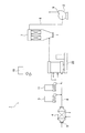
ところで、図18に示すように、粉体処理装置100の処理間隙を通過する気流は、粉体処理装置100の下流側に設けられた排風装置101によって引き起こされている。そして、粉体処理装置100には、原料供給装置102から供給される粉体と、冷却装置103から冷却されて供給される気体とが供給されるようになっている。また、粉体処理装置100から排出された処理済みの粉体は、粉体処理装置100と排風装置101との間に設けられたサイクロン104によって連続的に回収されている。すなわち、サイクロン104は、粉体処理装置100から排出された気体と粉体の混合体から処理済みの粉体を分離して回収している。分離された気体はバグフィルタ105を介して排風装置101に供給される。
By the way, as shown in FIG. 18, the airflow passing through the processing gap of the
そこで、粉体の処理時間を延ばすことを目的として、図18に示すように、サイクロン104によって回収された粉体を粉体処理装置100に再び供給して処理を行うことも効果的のように考えられる。
Therefore, for the purpose of extending the processing time of the powder, as shown in FIG. 18, it is also effective to supply the powder recovered by the
しかしながら、図18に示す例では、粉体処理装置100において処理された粉体が粉体処理装置100から一度排出されてサイクロン104に供給され、サイクロン104を通過した粉体が再び粉体処理装置100に戻されるため、粉体の循環径路が長くなる。このことにより、粉体が循環径路のうち処理間隙以外の部分において停留する可能性が高くなり、粉体の処理にムラが生じて、粉体を均一に処理することが困難になる。また、この例では、排風装置101の動力が不安定になり、このことによっても、粉体を均一に処理することが困難になり得る。
However, in the example shown in FIG. 18, the powder processed in the
本発明は、このような点を考慮してなされたものであり、粉体の処理時間を延ばして処理効果を向上させるとともに粉体の処理を均一化させることができる粉体処理装置および粉体処理設備を提供することを目的とする。 The present invention has been made in consideration of such points, and a powder processing apparatus and a powder capable of extending the processing time of the powder to improve the processing effect and uniformize the processing of the powder. The purpose is to provide treatment facilities.
本発明は、処理容器と、前記処理容器に設けられ、粉体と気体とを含む混合体が供給される供給口と、前記処理容器内に設けられた円筒状の固定子と、前記固定子の内周側であって、前記固定子に対して前記混合体が通過する処理間隙を介して回転可能に設けられた円筒状の回転子と、前記処理容器に設けられ、前記処理間隙を通過した前記混合体から前記気体を分離して排出するサイクロンと、前記サイクロンを通過した前記粉体を前記処理間隙に戻す戻し流路と、前記処理容器に設けられ、前記処理間隙を通過した前記粉体を排出する容器粉体排出口と、前記容器粉体排出口に設けられた排出口開閉弁と、を備えたことを特徴とする粉体処理装置を提供する。 The present invention provides a processing container, a supply port provided in the processing container to which a mixture containing powder and gas is supplied, a cylindrical stator provided in the processing container, and the stator A cylindrical rotor that is rotatably provided through a processing gap through which the mixture passes with respect to the stator, and is provided in the processing container and passes through the processing gap. A cyclone that separates and discharges the gas from the mixture, a return channel that returns the powder that has passed through the cyclone to the processing gap, and the powder that is provided in the processing container and passes through the processing gap. There is provided a powder processing apparatus comprising: a container powder discharge port for discharging a body; and a discharge port opening / closing valve provided at the container powder discharge port.
なお、上述した粉体処理装置において、前記サイクロンは、前記回転子の内周側に設けられた、前記粉体が流出するサイクロン粉体排出口を有し、前記回転子よりも前記供給口の側に、流路区画部材が設けられ、前記戻し流路は、前記回転子と前記流路区画部材との間に形成され、前記流路区画部材は、前記供給口から前記処理間隙への前記混合体の供給流路と、前記戻し流路とを区画している、ようにしてもよい。 In the above-described powder processing apparatus, the cyclone has a cyclone powder discharge port through which the powder flows out, which is provided on the inner peripheral side of the rotor. On the side, a flow path partition member is provided, the return flow path is formed between the rotor and the flow path partition member, and the flow path partition member is connected to the processing gap from the supply port. The supply channel for the mixture and the return channel may be partitioned.
また、上述した粉体処理装置において、前記戻し流路内に、前記戻し流路内を流れる前記粉体を前記処理間隙に案内する案内部材が設けられている、ようにしてもよい。 Further, in the powder processing apparatus described above, a guide member for guiding the powder flowing in the return channel to the processing gap may be provided in the return channel.
また、上述した粉体処理装置において、前記案内部材は半径方向に延びている、ようにしてもよい。 In the powder processing apparatus described above, the guide member may extend in the radial direction.
また、上述した粉体処理装置において、前記処理容器は、円筒状に形成され、前記排出口開閉弁は、前記処理容器の内周側面に設けられた座面と、前記座面に対して前記処理容器の内周側に離接可能に設けられた弁体と、を有している、ようにしてもよい。 Further, in the above-described powder processing apparatus, the processing container is formed in a cylindrical shape, and the discharge opening / closing valve is provided on a seating surface provided on an inner peripheral side surface of the processing container, and on the seating surface. And a valve body detachably provided on the inner peripheral side of the processing container.
また、上述した粉体処理装置において、前記容器粉体排出口に、前記処理容器の接線方向に延びる粉体排出管が連結されている、ようにしてもよい。 In the above-described powder processing apparatus, a powder discharge pipe extending in a tangential direction of the processing container may be connected to the container powder discharge port.
また、上述した粉体処理装置において、前記容器粉体排出口から排出された前記粉体を蓄積する粉体蓄積部を更に備えている、ようにしてもよい。 The above-described powder processing apparatus may further include a powder accumulation unit that accumulates the powder discharged from the container powder discharge port.
また、上述した粉体処理装置において、前記粉体蓄積部に蓄積された前記粉体を回収する粉体回収口と、前記粉体蓄積部と前記粉体回収口との間に直列に設けられた2つの回収口開閉弁と、を更に備えている、ようにしてもよい。 Further, in the above-described powder processing apparatus, a powder recovery port for recovering the powder accumulated in the powder accumulation unit, and a serial connection between the powder accumulation unit and the powder recovery port are provided. And two recovery port opening / closing valves.
また、上述した粉体処理装置において、前記サイクロンは、互いに並列に設けられた複数の第1サイクロンを有している、ようにしてもよい。 In the above-described powder processing apparatus, the cyclone may include a plurality of first cyclones provided in parallel to each other.
また、上述した粉体処理装置において、前記サイクロンは、前記第1サイクロンを通過した前記粉体から前記気体を分離する第2サイクロンを更に有している、ようにしてもよい。 In the above-described powder processing apparatus, the cyclone may further include a second cyclone that separates the gas from the powder that has passed through the first cyclone.
また、本発明は、上述した粉体処理装置と、前記粉体処理装置に前記気体を供給するとともに、前記粉体処理装置から前記気体を排出する気体給排装置と、前記粉体処理装置に供給される前記気体に原料としての前記粉体を供給する原料供給装置と、を備えたことを特徴とする粉体処理設備を提供する。 In addition, the present invention provides a powder processing apparatus, a gas supply / discharge apparatus that supplies the gas to the powder processing apparatus and discharges the gas from the powder processing apparatus, and the powder processing apparatus. A powder processing facility comprising: a raw material supply device that supplies the powder as a raw material to the gas to be supplied.
なお、上述した粉体処理設備において、制御装置を更に備え、前記制御装置は、前記原料供給装置から前記粉体を所定量供給した後、前記粉体の供給を停止し、前記粉体の供給を停止してから所定時間経過した後、前記排出口開閉弁を開くように、前記原料供給装置および前記排出口開閉弁を制御する、ようにしてもよい。 The powder processing facility described above further includes a control device, and the control device stops supplying the powder after supplying a predetermined amount of the powder from the raw material supply device, and supplies the powder. The raw material supply device and the discharge port on / off valve may be controlled so that the discharge port on / off valve is opened after a lapse of a predetermined time from the stop.
また、上述した粉体処理設備において、前記原料供給装置から供給される前記粉体とは異なる第2の粉体を原料として供給する第2の原料供給装置を更に備えている、ようにしてもよい。 The powder processing facility may further include a second raw material supply device that supplies, as a raw material, a second powder that is different from the powder supplied from the raw material supply device. Good.
本発明によれば、粉体の処理時間を延ばして処理効果を向上させるとともに粉体の処理を均一化させることができる。 ADVANTAGE OF THE INVENTION According to this invention, the processing time of powder can be extended, a processing effect can be improved, and the processing of powder can be made uniform.
以下、図面を参照して、本発明の実施の形態における粉体処理装置および粉体処理設備について説明する。 Hereinafter, a powder processing apparatus and powder processing equipment in an embodiment of the present invention will be described with reference to the drawings.
(第1の実施の形態)
図1乃至図13を用いて、本発明の第1の実施の形態における粉体処理装置および粉体処理設備について説明する。
(First embodiment)
A powder processing apparatus and powder processing equipment in the first embodiment of the present invention will be described with reference to FIGS.
ここでは、まず、処理対象となる粉体、粉体の処理について説明する。粉体としては、例えば、有機、無機系を問わず、トナー、黒鉛、ナイロン、酸化チタン等に代表される、平均粒径が数百μm以下の粉末が挙げられる。粉体の処理とは、例えば、平均粒径が5〜50μmの不規則粒形の粉体を球形化すること、粒子表面の凹凸を平滑化すること、または、例えば、平均粒径が5〜50μmの母粉体(第1の粉体)の表面に、母粉体の平均粒径に対して好ましくは1/10以下、より好ましくは1/100の粒径を持つ他の子粉体(第2の粉体)を付着させて粉体を複合化するなど、異なる機能を有する2種以上の粉体を複合化処理することを意味する。また、複合化処理においては、複合化した粉体の球形化も同時に行なわれる。さらに、粉体処理の他の例として、粒子状の粉体を粉砕して微細化することも挙げられる。 Here, first, the powder to be processed and the processing of the powder will be described. Examples of the powder include powders having an average particle size of several hundred μm or less, typified by toner, graphite, nylon, titanium oxide and the like, regardless of organic or inorganic type. The treatment of the powder is, for example, spheroidizing an irregular particle powder having an average particle diameter of 5 to 50 μm, smoothing irregularities on the particle surface, or, for example, an average particle diameter of 5 to 5 On the surface of the 50 μm mother powder (first powder), another sub-powder having a particle diameter of preferably 1/10 or less, more preferably 1/100 of the average particle diameter of the mother powder ( It means that two or more kinds of powders having different functions are combined, for example, the second powder is attached to form a composite powder. In the compounding process, the compounded powder is spheroidized at the same time. Furthermore, as another example of the powder processing, it is also possible to pulverize and refine the particulate powder.
本実施の形態の以下の説明では、1種の粉体を処理(例えば、球形化処理、平滑化処理、微細化処理)する場合を例にとって説明する。 In the following description of the present embodiment, a case where one kind of powder is processed (for example, spheroidizing process, smoothing process, and miniaturization process) will be described as an example.
図1に示すように、粉体処理設備1は、粉体と気体とを含む混合体が供給されて粉体処理が行われる粉体処理装置20と、粉体処理装置20に気体を供給するとともに、粉体処理装置20から気体を排出する排風装置2(気体給排装置)と、粉体処理装置20に供給される気体に原料としての粉体を供給する原料供給装置3と、を備えている。このうち排風装置2は、粉体処理装置20の下流側に設けられ、原料供給装置3は、粉体処理装置20の上流側に設けられている。
As shown in FIG. 1, the powder processing facility 1 supplies a gas to the
より具体的には、粉体処理装置20の上流側に冷却装置4が設けられている。冷却装置4は、気体(例えば空気)が吸引される吸引口5を有しており、吸引口5から吸引された気体を冷却する。冷却装置4と粉体処理装置20の供給口22(後述)は供給ダクト6によって連結されている。排風装置2が駆動されると、吸引口5から気体が吸引されて冷却装置4によって冷却され、供給ダクト6を介して粉体処理装置20の供給口22に供給される。冷却装置4には、クーラ等を使用して気体の冷却のみならず、除湿も可能にすることが好ましい。冷却温度は、処理対象となる原料によって適宜設定されるが、例えばトナーの場合には、粉体処理装置20から排出される気体の温度が60℃〜70℃を超えないように、粉体処理装置20に供給される気体が低温に維持される。このように粉体処理設備1が冷却装置4を備えることにより、粉体同士が融着すること、または粉体が固定子23若しくは回転子24に融着することを防止し、粉体の処理能力(処理量)を向上させることができる。特に、粉体が弱熱性材料または低融点材料である場合、または粉体の供給量が多い場合に顕著な効果を得ることができる。一方、処理対象の粉体が処理時の温度を上げることで処理効果が高まる材料である場合には、冷却装置4はヒータによって置き換えられ、ヒータ内を通る粉体を加熱するようにしてもよい。なお、冷却装置4は、粉体処理装置20の上流側であれば、原料供給装置3の下流側に設けられていてもよい。
More specifically, the cooling device 4 is provided on the upstream side of the
供給ダクト6内を流れる気体には、上述した原料供給装置3から原料としての粉体が供給され、供給された粉体が気体の流れに分散されて粉体と気体とを含む混合体をなし、この混合体が粉体処理装置20に供給される。原料供給装置3には、スクリュー式またはテーブル式などの供給装置を使用することができるが、これに限らず、粉体を供給ダクト6に供給可能であれば任意の供給装置を使用することができる。
The gas flowing in the supply duct 6 is supplied with the powder as the raw material from the raw
粉体処理装置20は、供給された混合体に含まれる粉体を処理する。そして、粉体処理装置20は、処理された粉体から気体を分離して排出すると共に、処理された粉体を回収可能に構成されている。詳細は後述する。
The
粉体処理装置20の下流側には、バグフィルタ7が設けられており、粉体処理装置20のサイクロン気体排出口44(後述)から排出された気体が、バグフィルタ7に供給されるようになっている。
A
バグフィルタ7には、排出ダクト8を介して上述の排風装置2が連結されており、バグフィルタ7から排出された気体が排風装置2に供給されるようになっている。排風装置2は、気体を排出する排出口9を有している。
The
次に、図2乃至図13を用いて粉体処理装置20について説明する。
Next, the
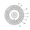
図2に示すように、粉体処理装置20は、処理容器21と、処理容器21に設けられ、上述した供給ダクト6から粉体と気体とを含む混合体が供給される供給口22と、処理容器21内に設けられた固定子23と、固定子23の内周側に回転可能に設けられた円筒状の回転子24と、を備えている。このうち処理容器21は、図2に示す例では、各々が円筒状に形成された4つの容器(すなわち、供給口22が設けられた容器21a、固定子23が取り付けられた容器21b、後述する容器粉体排出口55が設けられた容器21c、およびその上方に設けられた容器21d)を組み合わせることによって、円筒状に形成されている。供給口22は、処理容器21の接線方向に沿って混合体を処理容器21内に流入させるように形成されていることが好ましい。回転子24は、固定子23に対して混合体が通過する処理間隙25を介して設けられている。言い換えると、固定子23と回転子24との間に処理間隙25が形成されており、供給口22に供給された混合体が処理間隙25を通過可能になっている。
As shown in FIG. 2, the
固定子23は、金属等で円筒状に作製され、回転子24の外周面を囲むように形成されている。固定子23の内周面は、超硬合金やセラミックなどの耐摩耗材料により形成されていることが好ましい。あるいは、硬質クロムメッキまたは超硬合金等の溶射により耐摩耗処理されていてもよい。
The
回転子24に、垂直方向に延びる回転軸26が連結されている。処理容器21の底部(図2に示す例では容器21a)には基台Bが設けられており、回転軸26は、この基台Bに設けられた軸受Rにより回転可能に支持されている。このようにして、回転子24は、基台Bに回転可能に支持されているが、処理容器21の頂部(図2に示す例では容器21d)に設けられた頂板21eには支持されていない。このようにして、回転子24は、片持ち状に支持されている。
A rotating
基台Bには、回転子24を回転駆動するモータ等の回転駆動部27が設けられている。回転駆動部27は、駆動軸28を有しており、この駆動軸28にVプーリー29が装着されている。上述した回転軸26にも同様のVプーリー30が装着されており、これらのVプーリー29、30に、Vベルト31が巻き掛けられている。このような構成により、回転駆動部27の回転駆動力が回転子24に伝達されて回転子24が回転する。本実施の形態による回転子24は、一例として8000rpmの回転速度で回転するが、これに限られることはなく、回転子24の回転速度は、回転駆動部27によって調整可能であることが好適である。この場合、黒鉛のような塑性変形しない粉体や、低融点の粉体など性状が異なる種々の粉体に対して、最適な回転速度で回転子24を回転させて、適切な粉体処理を行うことが可能となる。
The base B is provided with a
回転子24は、金属等で円筒状に作製され、その外周面が超硬合金やセラミックなどの耐摩耗材料により形成されていることが好ましい。あるいは、回転子24は、硬質クロムメッキまたは超硬合金等の容射により耐摩耗処理されていてもよい。
The
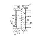
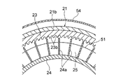
図3および図4に示すように、固定子23の内周面には、回転子24と同心状に形成された周方向に延びる円周溝23aが多段に設けられていてもよい。円周溝23aは、例えば、図4に示すように台形状に形成されていてもよい。一方、回転子24の外周面には、回転子24の軸方向に延びる多数のブレード24aが、周方向に離間して設けられていてもよい。この場合、ブレード24aは、固定子23と回転子24との間の処理間隙25に存在し、固定子23の内周面とは接触しない状態で狭い隙間を保ったまま、固定子23の内周面に沿って回転する。図3および図4に示す例では、固定子23に円周溝23aが設けられているため、粉体同士の接触が過度に強くなることを抑制でき、粉体の粉砕を抑制し、粉体を高精度に球形化または平滑化することができる。また、円周溝23a内に粉体を滞留させることができ、処理間隙25内における粉体の滞留時間を延ばして、処理効果を向上させることができる。
As shown in FIGS. 3 and 4,
なお、固定子23の内周面に円周溝23aを設ける場合には、図5に示すように、ブレード24aの外周面に複数の突起24bを設けるようにしてもよい。図5に示す例においては、複数の突起24bは、周方向に並んで配置されるとともに多段に配置されている。各突起24bは、固定子23の内周面(円周溝23aの入口)を越えて、対応する円周溝23a内に入り込んでいる。この場合、突起24bは、円周溝23aの内壁とは接触しない状態で狭い隙間を保ったまま、円周溝23a内で円周溝23aに沿って回転する。図5に示す例では、円周溝23aの断面と突起24bの投影断面に大きな差がない限り、回転子24の回転により円周溝23a内に回転子24の回転速度と同等の旋回流が発生する。このため、円周溝23a内に滞留する粉体の滞留時間を延ばすことができ、粉体をより一層高精度に球形化または平滑化することができ、処理効果を向上させることができる。なお、図5に示す形態では、固定子23を周方向に2つ以上に分割して回転子24の側方からあてがうように組み立てることが好適である。
In addition, when providing the
また、固定子23の内周面には、円周溝23aではなく、図6乃至図8に示すように、複数の固定子側軸方向溝23bが設けられていてもよい。固定子側軸方向溝23bは、回転子24の軸方向に延びており、周方向に離間して設けられている。固定子側軸方向溝23bは、例えば、図7に示すようにU字形状に形成されていてもよく、あるいは図8に示すように概略的に三角形状に形成されていてもよい。回転子24の外周面には、図4に示す例と同様にして回転子24の軸方向に延びる多数のブレード24aが、周方向に離間して設けられている。この場合、ブレード24aは、固定子23の内周面とは接触しない状態で狭い隙間を保ったまま、固定子23の内周面に沿って回転する。図6乃至図8に示す例では、後述する図9および図10に示す例と同様に、粉体を粉砕しやすくなり、粉体を微細化することが可能となる。また、図6乃至図8に示す例は、図9および図10に示す例よりも処理間隙25が広くなるため、比較的大きい原料を処理することが可能となるとともに、処理間隙25における気体の流れの圧損を低減することができる。また、圧損を低減できるため、回転子24を低回転速度で粉体を処理することができる。このように、図6乃至図8に示す例は、汎用性を有することができる。
Further, instead of the
固定子23の内周面に固定子側軸方向溝23bを設ける場合には、図9および図10に示すように、回転子24の外周面に、複数の回転子側軸方向溝24cが設けられていてもよい。回転子側軸方向溝24cは、固定子側軸方向溝23bと同様に回転子24の軸方向に延びており、周方向に離間して設けられている。この場合、回転子24は、固定子23の内周面とは接触しない状態で狭い隙間を保ったまま、固定子23の内周面に沿って回転する。図9および図10に示す例では、図6乃至図8に示す例よりも粉体を粉砕しやすくなり、粉体をより一層微細化することが可能となる。すなわち、図9および図10に示す固定子側軸方向溝23bおよび回転子側軸方向溝24cの形状は、粉体を粉砕して微細化することに適している。また、図9および図10に示す例では、図6乃至図8に示す例よりも処理間隙25が狭くなる傾向にあるため、後述する戻し流路50に羽根52を設けて、羽根52を回転子24と共に回転させることが好適である。このことにより、後述するように、戻し流路50内に中心側から外周側に向う流れを形成することができ、供給口22に供給された気体が戻し流路50を通ってサイクロン40(後述)に逆流することを防止して、処理間隙25にスムースに流入することができる。この場合、回転子24の回転速度を高めることにより、逆流防止の効果を高めることができ、さらには処理間隙25における粉体の粉砕力を高めることもできる。このため、粉体の粉砕力をより一層高めることができ、粉体をより一層微細化することが可能となる。なお、図10に示す例においては、固定子側軸方向溝23bおよび回転子側軸方向溝24cは、いずれもU字形状に形成されているが、これに限られることはない。
When the stator-side
図2に示すように、処理容器21内には、固定子23と回転子24との間の処理間隙25を通過した混合体から気体を分離して排出するサイクロン40が設けられている。サイクロン40は、サイクロン本体41と、サイクロン本体41の上方に設けられ、処理間隙25を通過した混合体が流入するサイクロン流入口42と、サイクロン本体41の下方に設けられ、サイクロン本体41を通過した粉体を排出するサイクロン粉体排出口43と、を有している。このように本実施の形態によるサイクロン40は、単一のサイクロンとして構成されている。サイクロン流入口42は、回転子24の上方に配置されている。図11に示す例においては、サイクロン流入口42は、4つ設けられているが、これに限られることはない。サイクロン粉体排出口43は、回転子24の下部であって回転子24の内周側に設けられている。なお、サイクロン40は、処理容器21に対して回転不能に取り付けられている。ところで、混合体から気体を分離するための構成として、自身が回転することにより気体を分離する分級器などが挙げられるが、本実施の形態のようなサイクロン40は、処理容器21に回転不能に取り付けられるため、分級器を用いる場合に比べて、粉体処理装置20の構造を簡素化することが可能となる。
As shown in FIG. 2, a
サイクロン本体41の上部には、粉体から分離された気体を排出するサイクロン気体排出口44が設けられている。サイクロン気体排出口44は、サイクロン流入口42の中心部に配置されて、サイクロン本体41の内部から上方に延びている。処理容器21の頂板21eには、処理容器21の外方に延びる容器気体排出口53が設けられている。図1に示す例においては、容器気体排出口53は、サイクロン気体排出口44と一体に連続的に形成されて連通し、容器気体排出口53およびサイクロン気体排出口44は上述した排風装置2によって吸引されている。この吸引力によって、サイクロン40において分離された気体がサイクロン気体排出口44を通過して容器気体排出口53から排出されるようになっている。すなわち、この吸引力によりサイクロン40内で粉体から気体が分離されるようになっている。容器気体排出口53から排出された気体は、上述したバグフィルタ7に供給される
In the upper part of the cyclone
回転子24の下方には、戻し流路50が設けられている。戻し流路50は、図12に示す例においては、サイクロン粉体排出口43から、固定子23と回転子24との間の処理間隙25に延びて連通している。このような戻し流路50によって、サイクロン本体41を通過してサイクロン粉体排出口43から排出された粉体は処理間隙25に戻されるようになっている。
A
図2に示すように、回転子24よりも供給口22の側に流路区画部材51が設けられている。より具体的には、流路区画部材51は、回転子24の下方に、回転子24に対して離間して設けられており、回転子24と流路区画部材51との間に上述した戻し流路50が形成されている。そして、流路区画部材51は、供給口22から処理間隙25への混合体の供給流路と、サイクロン粉体排出口43から処理間隙25へ向う戻し流路50とを区画しており、供給口22から処理間隙25へ流れる混合体が、戻し流路50に流入されることを防止している。
As shown in FIG. 2, a flow
戻し流路50内には、戻し流路50内を流れる粉体を処理間隙25に案内する複数の羽根52(案内部材)が設けられている。これらの羽根52は、図12に示すように、周方向に離間して配置され、各々が半径方向に延びている。また、羽根52は、回転子24と流路区画部材51とを連結しており、回転子24と流路区画部材51と羽根52は、一体に回転するようになっている。このため、戻し流路50内を流れる粉体と気体の混合体に対して、羽根52から周方向の速度成分が付与され、これにより、粉体に遠心力が生じて、粉体に外周側に向う力が生じる。このようにして、サイクロン粉体排出口43から排出された粉体が、処理間隙25にスムースに流れるようになっている。
In the
ところで、図2に示すように、処理容器21の外周側に加熱・冷却ジャケット54が設けられていてもよい。加熱・冷却ジャケット54は、固定子23に対向する位置、すなわち固定子23を外周側から囲むように形成されており、固定子23を加熱または冷却するようになっている。このことにより、処理間隙25内の粉体を、粉体の性状に応じて、加熱または冷却し、処理効果を高めることが可能となっている。例えば、加熱・冷却ジャケット54内には、−20℃〜90℃の冷却液または加熱液が供給されて、粉体が弱熱性である場合には固定子23を冷却して処理間隙25内の温度上昇を抑制し、処理時の温度を上げることで処理効果が高まる粉体の場合には、固定子23を加熱して処理間隙25内の温度を上昇させることが好ましい。
Incidentally, as shown in FIG. 2, a heating /
図2および図13に示すように、処理容器21には、処理間隙25を通過した粉体(すなわち、処理済みの粉体)を排出する容器粉体排出口55が設けられている。容器粉体排出口55は、固定子23の上方に配置されている。容器粉体排出口55には、排出口ダンパ56(排出口開閉弁)が設けられている。排出口ダンパ56は、処理容器21の外周側面に設けられた座面56aと、座面56aに対して処理容器21の外周側に離接可能に設けられた弁体56bと、を有している。例えば、座面56aは、処理容器21に固定されたフランジの外面とすることが好適である。
As shown in FIGS. 2 and 13, the
容器粉体排出口55には、回転子24の半径方向に延びる粉体排出管57が連結されている。上述した排出口ダンパ56の弁体56bは、粉体排出管57の軸線方向に移動可能になっている。弁体56bには、弁棒56cを介して弁体駆動部56d(例えば、エアシリンダ)が連結されており、この弁体駆動部56dによって、弁体56bは、座面56aに着座した閉位置(図2の実線で示す位置)と、座面56aから処理容器21の外周側処理容器21に離間した開位置(図2の二点鎖線で示す位置)との間で移動可能になっている。
A
図2に示すように、粉体排出管57には、粉体案内管58を介して粉体蓄積部59が連結されている。粉体蓄積部59は、容器粉体排出口55から排出された処理済みの粉体を蓄積する。粉体案内管58は、粉体排出管57から斜め下方に延びるように形成されている。
As shown in FIG. 2, a
粉体蓄積部59の下流側には、粉体蓄積部59に蓄積された粉体を回収する粉体回収口60が設けられている。粉体蓄積部59と粉体回収口60との間に、2つの回収口ダンパ61、62(回収口開閉弁)が直列に設けられている。
A
図1に示すように、粉体処理設備1は、制御装置10を更に備えている。この制御装置10は、上述した原料供給装置3および粉体処理装置20の排出口ダンパ56を制御し、原料供給装置3から粉体を所定量供給した後、粉体の供給が停止され、粉体の供給が停止されてから所定時間経過した後、粉体処理装置20の排出口ダンパ56が開く。このようにして、所定時間処理が行われた処理済みの粉体が、容器粉体排出口55から排出されて、粉体蓄積部59に蓄積されるようになっている。
As shown in FIG. 1, the powder processing facility 1 further includes a
次に、このような構成からなる本実施の形態の作用、すなわち本実施の形態による粉体処理設備1における粉体処理方法について説明する。 Next, the operation of the present embodiment having such a configuration, that is, the powder processing method in the powder processing facility 1 according to the present embodiment will be described.
まず、図1に示す排風装置2が駆動され、冷却装置4の吸引口5から気体が吸引される。このことにより、供給ダクト6、粉体処理装置20および排出ダクト8をこの順で流れる気体の流れが形成される。また、図2に示す粉体処理装置20内では、供給口22から処理間隙25を通過して容器気体排出口53に流れる気体の流れが形成される。なお、供給ダクト6に供給される粉体は、冷却装置4によって必要に応じて所望の温度に冷却される。あるいは冷却装置4がヒータに置き換えられる場合には、供給ダクト6に供給される粉体は、ヒータによって所望の温度に加熱される。排出ダクト8を流れる気体は、排風装置2の排出口9から排出される。
First, the air exhaust device 2 shown in FIG. 1 is driven, and gas is sucked from the suction port 5 of the cooling device 4. As a result, a gas flow that flows through the supply duct 6, the
続いて、図2に示す粉体処理装置20の回転駆動部27が駆動されて、回転子24が回転する。このことにより、固定子23と回転子24との間に形成された処理間隙25内に、回転子24の回転速度に応じた旋回流が発生する。
Subsequently, the
次に、原料供給装置3が駆動されて、供給ダクト6内に原料としての粉体が供給される。供給ダクト6内に供給された粉体は、供給ダクト6内の気体の流れに分散して混合体をなし、原料供給装置3の供給口22に供給される。
Next, the raw
粉体処理装置20の供給口22に供給された混合体は、固定子23と回転子24との間の処理間隙25に流入する。例えば、図4等に示すように固定子23の内周面に円周溝23aが形成されている場合には、処理間隙25内の粉体は、旋回流によって円周溝23aの内壁に押し付けられながら、処理間隙25の下端(上流端)から上端(下流端)まで移動する。このとき、粉体は、円周溝23aの内壁と接触し、または粉体同士が接触し、球形化処理または平滑化処理される。
The mixture supplied to the
処理間隙25を通過した混合体は、図2に示すサイクロン40のサイクロン流入口42に達する。この際、容器粉体排出口55に設けられた排出口ダンパ56は閉じられている。
The mixture that has passed through the
サイクロン流入口42に達した混合体は、サイクロン流入口42からサイクロン本体41内に流入して、旋回しながら下降する。この間、粉体は、遠心力によってサイクロン本体41の内壁面に沿って旋回しながら下降し、サイクロン粉体排出口43に達する。一方、気体は、排風装置2の吸引力によって、サイクロン本体41の中心部で上昇に転じ、サイクロン気体排出口44を通過して容器気体排出口53に達する。
The mixture that has reached the
サイクロン粉体排出口43に達した粉体は、周囲の気体とともに戻し流路50を通過して処理間隙25に戻される。戻し流路50を流れる際、戻し流路50内の粉体および気体には、回転子24と流路区画部材51とを連結している羽根52から、回転子24の回転方向と同じ方向の周方向速度成分が付与される。このことにより、粉体および気体に遠心力が生じて粉体および気体は外周側に向って流れ、戻し流路50内に外周側に向う流れが形成される。また、この際、処理間隙25には、回転子24の下端から上端に向う気体の流れが形成されるとともに、回転子24のブレード24aによって旋回流が形成されている。このような処理間隙25内の流れによっても、戻し流路50内に外周側に向う流れが形成される。このため、サイクロン粉体排出口43に達した粉体は戻し流路50に吸引されて、戻し流路50内に形成された外周側に向う流れに乗って処理間隙25に達する。このようにして、サイクロン粉体排出口43に達した粉体は、戻し流路50によって処理間隙25にスムースに戻されるとともに、サイクロン粉体排出口43に達した粉体がサイクロン本体41内を上昇してサイクロン気体排出口44に逆流し、粉体処理装置20から排出されることを防止している。
The powder that has reached the
そして、戻し流路50から処理間隙25に達した粉体は、処理間隙25において再び球形化処理または平滑化処理される。このようにして、粉体処理装置20内において粉体が循環して、粉体の処理が繰り返される。粉体が循環している間、排風装置2が駆動され続け、粉体処理装置20の供給口22から容器気体排出口53に向う流れが形成されている。このことにより、処理間隙25を気体が連続的に通過し、処理間隙25内の粉体の温度が上昇することを抑制している。
Then, the powder that has reached the
一方、容器気体排出口53に達した気体は、容器気体排出口53から排出されて、粉体処理装置20の下流側に設けられたバグフィルタ7(図1参照)に供給される。
On the other hand, the gas that has reached the container
バグフィルタ7を通過した気体は、排出ダクト8を通過して排風装置2に供給され、排風装置2の排出口9から排出される。
The gas that has passed through the
ところで、原料供給装置3および排出口ダンパ56が制御装置10により制御されており、原料供給装置3による粉体の供給は、原料供給装置3から粉体を所定量供給した後に停止され、粉体の供給を停止してから所定時間経過した後、排出口ダンパ56が開く。
By the way, the raw
より具体的には、まず、原料供給装置3が駆動されて、原料としての粉体の供給が開始される。
More specifically, first, the raw
続いて、粉体が所定量供給された後、粉体の供給が停止される。この際、例えば、原料供給装置3から供給される粉体の単位時間当たりの流量から、所定の供給量となる供給時間を求めて、この供給時間だけ粉体を供給するようにしてもよい。なお、原料供給装置3による粉体の供給量は、例えば、粉体処理装置20の容量や、処理能力、回転駆動部27の容量などに基づいて設定することが好適である。
Subsequently, after a predetermined amount of powder is supplied, the supply of powder is stopped. At this time, for example, the supply time for a predetermined supply amount may be obtained from the flow rate per unit time of the powder supplied from the raw
次に、粉体の供給を停止してから所定の時間経過した後、排出口ダンパ56が開き、処理された粉体が容器粉体排出口55から排出される。このことにより、所定の処理時間にわたって、粉体が処理間隙25、サイクロン40、戻し流路50を循環して球形化処理または平滑化処理される。この処理時間を調整することにより、粉体の処理効果を調整することが可能となる。なお、処理容器21内の粉体は旋回しているため、排出口ダンパ56が開くと、旋回する粉体は、遠心力によって容器粉体排出口55からスムースに排出される。
Next, after a predetermined time has passed since the supply of the powder was stopped, the
容器粉体排出口55から排出された処理済みの粉体は、粉体排出管57および粉体案内管58を通過して粉体蓄積部59に達する。この際、粉体蓄積部59の下流側に設けられた2つの回収口ダンパ61、62は、閉じられている。このことにより、粉体蓄積部59に達した粉体が蓄積されるとともに、粉体回収口60から粉体蓄積部59を通過して処理容器21内に気体が逆流することを防止している。
The processed powder discharged from the container
粉体蓄積部59に処理済みの粉体が蓄積された後、排出口ダンパ56が閉じられる。
After the processed powder is accumulated in the
粉体蓄積部59に蓄積された粉体を回収する際には、まず、2つの回収口ダンパ61、62のうち上流側の第1回収口ダンパ61を開く。このことにより、粉体蓄積部59に蓄積された粉体が、2つの回収口ダンパ61、62の間の領域に一時的に蓄積される。この場合においても、下流側の第2回収口ダンパ62が閉じられているため、粉体回収口60から処理容器21内に気体が逆流することを防止できる。
When collecting the powder accumulated in the
続いて、第1回収口ダンパ61を閉じ、その後、下流側の第2回収口ダンパ62を開く。このことにより、2つの回収口ダンパ61、62の間の領域に一時的に蓄積されていた粉体が、粉体回収口60を介して回収される。第2回収口ダンパ62を開いた際には第1回収口ダンパ61は閉じられているため、粉体回収口60から処理容器21内に気体が逆流することを防止できる。
Subsequently, the first
粉体を回収した後、第2回収口ダンパ62を閉じる。
After collecting the powder, the second
このようにして、粉体を球形化処理して回収する一連の工程が終了する。続いて新たな粉体を処理する場合には、再び原料供給装置3から供給ダクト6に原料としての粉体を供給して、上述した工程を繰り返せばよい。なお、排出口ダンパ56を閉じていれば、粉体蓄積部59に蓄積されていた粉体を回収するのと並行して、処理容器21内で粉体の処理を行うこともできる。
In this way, a series of steps for spheroidizing and collecting the powder is completed. Subsequently, when processing a new powder, the powder as the raw material is again supplied from the raw
このように本実施の形態によれば、固定子23と回転子24との間に設けられた処理間隙25を通過した混合体に含まれる粉体が、サイクロン40および戻し流路50を通過して、再び処理間隙25に戻される。このことにより、粉体処理装置20内において粉体を循環させて、処理間隙25を複数回通過させることができ、粉体の処理を繰り返すことができる。このため、粉体の処理時間を延ばすことができ、粉体の処理効果を向上させることができる。
As described above, according to the present embodiment, the powder contained in the mixture that has passed through the
また、本実施の形態によれば、処理容器21内に設けられた固定子23と回転子24との間の処理間隙25と、同様に処理容器21内に設けられたサイクロン40および戻し流路50を通過させて粉体を循環させることができる。このことにより、粉体の循環径路を短くすることができ、粉体が循環径路のうち処理間隙25以外の部分において停留することを抑制できる。このため、粉体の処理にムラが生じることを抑制し、粉体の処理を均一化させることができる。
Further, according to the present embodiment, the
また、本実施の形態によれば、回転子24の下方に流路区画部材51が設けられ、この流路区画部材51によって、供給口22から処理間隙25への混合体の供給流路と、戻し流路50とが区画されている。このことにより、供給口22に供給された混合体が、処理間隙25を通過することなくサイクロン40に直接的に流れることを防止できるとともに、戻し流路50内の粉体が、サイクロン40に逆流することを防止できる。このため、粉体処理装置20内において粉体をスムースに循環させることができる。
Further, according to the present embodiment, the flow
また、本実施の形態によれば、原料供給装置3による粉体の供給を停止してから所定時間経過した後に排出口ダンパ56が開く。このことにより、この処理時間の間、粉体の処理を連続的に行うことができ、粉体を効率良く処理することができる。また、この処理時間を調整することにより、種々の粉体に対して適切な処理を行うことができ、粉体処理装置20の汎用性を向上させることができる。
Further, according to the present embodiment, the
また、本実施の形態によれば、戻し流路50内に、戻し流路50内を流れる粉体を処理間隙25に案内する羽根52が設けられている。このことにより、戻し流路50内を流れる粉体および気体に対して羽根52から周方向の速度成分を付与することができ、粉体および気体に遠心力を生じさせることができる。このため、戻し流路50内に中心側から外周側に向う流れを形成することができ、戻し流路50内の粉体を処理間隙25にスムースに流すことができる。また、羽根52が回転子24とともに回転することにより、供給口22に供給された気体が戻し流路50を通ってサイクロン40に逆流することを防止でき、サイクロン40内の粉体がサイクロン気体排出口44に逆流して粉体処理装置20から排出されることを防止できる。とりわけ、本実施の形態によれば、案内部材は半径方向に延びているため、戻し流路50内を流れる粉体および気体に対して効果的に周方向の速度成分を付与することができる。
Further, according to the present embodiment, the
なお、上述した本実施の形態においては、排出口ダンパ56が、処理容器21の外周側面に設けられた座面56aと、座面56aに離接可能に設けられた弁体56bと、を有し、弁体56bが、座面56aから処理容器21の外周側に移動可能になっている例について説明した。しかしながら、このことに限られることはなく、図14に示すように、排出口ダンパ56の座面56aが処理容器21の内周側面に設けられ、弁体56bが、座面56aに対して処理容器21の内周側に離接可能になっていてもよい。この場合、弁体56bは、開位置(図14の二点鎖線で示す位置)において、処理容器21の内周側に位置付けられる。このため、処理容器21内で旋回している粉体は、容器粉体排出口55に容易に流入することができ、粉体をスムースに排出することができる。
In the present embodiment described above, the
また、図14に示す例においては、粉体排出管57は、処理容器21の接線方向に延びている。このことにより、処理容器21内で旋回している粉体は、粉体排出管57内に容易に流入することができ、粉体をスムースに排出することができる。なお、図14に示す例においては、弁棒56cは、この粉体排出管57の軸線方向に傾斜する方向に延びている。
In the example shown in FIG. 14, the
なお、粉体排出管57に、図1に示す排風装置2または他の排風装置(図示せず)が連結され、粉体排出管57内の気体が吸引されるようにしてもよい。この場合、粉体を迅速に処理容器21から排出することができ、粉体の排出時間を短縮することができる。
The
また、上述した本実施の形態においては、1種の粉体を処理(球形化処理、平滑化処理、微細化処理など)する粉体処理設備1の例について説明した。しかしながら、このことに限られることはなく、2種以上の粉体を複合化処理する粉体処理設備1にも、上述した粉体処理装置20を適用することができる。図15に、一例として、2種の粉体を複合化処理する粉体処理設備1が示されている。
Moreover, in this Embodiment mentioned above, the example of the powder processing equipment 1 which processes 1 type of powder (spheroidization process, smoothing process, refinement | miniaturization process, etc.) was demonstrated. However, the present invention is not limited to this, and the above-described
図15に示す粉体処理設備1においては、上述した原料供給装置3が原料として母粉体を供給し、この母粉体とは異なる子粉体(第2の粉体)を原料として供給する第2の(他の)原料供給装置11を更に備えている。第2の原料供給装置11は、原料供給装置3と同様の構成とすることができ。すなわち、原料供給装置3から供給ダクト6内に母粉体が供給され、第2の原料供給装置11から供給ダクト6内に子粉体が供給される。このことにより、供給ダクト6内に供給された母粉体と子粉体が、供給ダクト6内の気体の流れに分散して混合体をなし、粉体処理装置20の供給口22に供給される。なお、図15に示す例では、原料供給装置3の下流側に第2の原料供給装置11が設けられているが、これに限られることはない。また、3種以上の粉体を原料とする場合には、このような原料供給装置を、粉体の種類毎に設ければよい。
In the powder processing facility 1 shown in FIG. 15, the raw
粉体処理装置20に供給された混合体に含まれる母粉体および子粉体は、上述した球形化処理などと同様の原理により複合化処理される。すなわち、粉体処理装置20の供給口22に供給された母粉体および子粉体は、固定子23と回転子24との間に形成された処理間隙25に流入する。処理間隙25内の粉体は、旋回流によって円周溝23aの内壁に押し付けられ、処理間隙25の下端(上流端)から上端(下流端)まで移動する。このとき、母粉体と子粉体は、円周溝23aの内壁と接触し、または、母粉体と子粉体とが接触する。これにより、母粉体の表面に子粉体が付着して複合化処理される。また、このような接触により、複合化された粉体が球形化処理される。このため、粉体の複合化処理を繰り返して粉体の複合化処理時間を延ばすことができ、粉体の複合化処理効果を向上させることができる。
The mother powder and the child powder contained in the mixture supplied to the
図15に示す例では、母粉体と子粉体とを別々に供給ダクト6に供給するようにしているが、これに限られることはなく、任意の方法を採用することができる。例えば、母粉体と子粉体とを予め混合してから供給ダクト6に供給するようにしてもよく、あるいは、別途混合機(図示せず)を設けて、母粉体と子粉体とを所定の割合で混合してから供給ダクト6に供給するようにしてもよい。 In the example shown in FIG. 15, the mother powder and the child powder are separately supplied to the supply duct 6, but the present invention is not limited to this, and any method can be adopted. For example, the mother powder and the child powder may be mixed in advance and then supplied to the supply duct 6, or a separate mixer (not shown) may be provided to May be supplied to the supply duct 6 after being mixed at a predetermined ratio.
また、上述した本実施の形態においては、冷却装置4の吸引口5から吸引された気体が、供給ダクト6、粉体処理装置20、排出ダクト8を通過して、排風装置2の排出口9から排出されるような一方向に気体を流す開回路式の粉体処理設備1を例にとって説明した。しかしながら、このことに限られることはなく、粉体処理設備1は、排風装置2の排出口9から排出される気体を冷却装置4の吸引口5に戻して、気体が循環するような閉回路式としてもよい。
Moreover, in this Embodiment mentioned above, the gas attracted | sucked from the suction port 5 of the cooling device 4 passes the supply duct 6, the
(第2の実施の形態)
次に、図16および図17を用いて、本発明の第2の実施の形態における粉体処理装置および粉体処理設備について説明する。
(Second Embodiment)
Next, the powder processing apparatus and the powder processing equipment in the second embodiment of the present invention will be described with reference to FIGS.
図16および図17に示す第2の実施の形態においては、サイクロンが、互いに並列に設けられた複数の第1サイクロンと、第1サイクロンを通過した粉体から気体を分離する第2サイクロンと、を有している点が主に異なり、他の構成は、図1乃至図13に示す第1の実施の形態と略同一である。なお、図16および図17において、図1乃至図13に示す第1の実施の形態と同一部分には同一符号を付して詳細な説明は省略する。 In the second embodiment shown in FIGS. 16 and 17, the cyclone has a plurality of first cyclones provided in parallel to each other, and a second cyclone that separates gas from the powder that has passed through the first cyclone, The other points are substantially the same as those of the first embodiment shown in FIGS. 1 to 13. 16 and 17, the same parts as those in the first embodiment shown in FIGS. 1 to 13 are denoted by the same reference numerals, and detailed description thereof is omitted.
図16および図17に示すように、本実施の形態によるサイクロン40は、互いに並列に設けられた複数の第1サイクロン70と、第1サイクロン70を通過した粉体から気体を分離する第2サイクロン71と、を有している。図16および図17に示す例においては、処理容器21内に4つの第1サイクロン70が設けられており、略同一の高さ位置に配置されている。処理間隙25を通過して戻し流路50に向う粉体は、各第1サイクロン70に分流されて、並列に流れるようになっている。このように、本実施の形態では、サイクロン40が、マルチサイクロン構造を有している。
As shown in FIGS. 16 and 17, the
本実施の形態によるサイクロン流入口42は、対応する第1サイクロン70の上部に設けられている。サイクロン粉体排出口43は、第2サイクロン71の下部に設けられている。各第1サイクロン70は第2サイクロン71に連結されており、第1サイクロン70を通過した混合体が連通口72を通過して第2サイクロン71に流入されるようになっている。
The
各第1サイクロン70の上部には、粉体から分離された気体を排出させるサイクロン気体排出口44が設けられている。サイクロン気体排出口44は、第1サイクロン70の上部かつ中心部に配置されて、第1サイクロン70の内部から上方に延びている。処理容器21の頂板21eには、容器気体排出口53が設けられており、容器気体排出口53はサイクロン気体排出口44と連通し、容器気体排出口53およびサイクロン気体排出口44は上述した排風装置2によって吸引されている。この吸引力によって、第1サイクロン70において分離された気体がサイクロン気体排出口44を通過して容器気体排出口53から排出されるようになっている。すなわち、この吸引力により第1サイクロン70および第2サイクロン71内で粉体から気体が分離されるようになっている。容器気体排出口53から排出された気体は、上述したバグフィルタ7に供給される。
A
処理間隙25を通過してサイクロン流入口42に達した混合体は、サイクロン流入口42から第1サイクロン70内に流入して、各第1サイクロン70内において旋回しながら下降する。この間、粉体は、遠心力によって第1サイクロン70の内壁面に沿って旋回しながら下降し、連通口72に達する。一方、第1サイクロン70内において粉体から分離された気体は、排風装置2の吸引力によって、第1サイクロン70の中心部で上昇に転じ、対応するサイクロン気体排出口44を通過して容器気体排出口53に達する。
The mixture that has passed through the
連通口72に達した混合体は、旋回しながら連通口72を通過し、第2サイクロン71に旋回しながら流入する。そして、第2サイクロン71に流入した混合体は、旋回しながら下降する。この間、粉体は、遠心力によって第2サイクロン71の内壁面に沿って旋回しながら下降し、サイクロン粉体排出口43に達する。一方、気体は、第2サイクロン71本体の中心部で上昇に転じ、連通口72を通過して第1サイクロン70に流入して、第1サイクロン70内において粉体から分離された気体とともに、サイクロン気体排出口44を通過して容器気体排出口53から排出される。
The mixture that has reached the
このように本実施の形態によれば、サイクロン40が、並列に設けられた複数の第1サイクロン70を有している。このことにより、サイクロン流入口42に達した混合体を、各第1サイクロン70に分流させて、各第1サイクロン70において、粉体から気体を分離することができる。このため、処理間隙25を通過した混合体から複数の第1サイクロン70によって気体を分離することができ、サイクロン40における気体の分離効率を向上させて、製品としての処理済み粉体の回収効率を向上させることができる。
Thus, according to this Embodiment, the
また、本実施の形態によれば、サイクロン40が、第1サイクロン70を通過した粉体から気体を分離する第2サイクロン71を更に有している。このことにより、サイクロン40全体として気体の分離効率をより一層向上させることができ、製品としての処理済み粉体の回収効率をより一層向上させることができる。
Further, according to the present embodiment, the
以上、本発明の実施の形態について詳細に説明してきたが、本発明による粉体処理装置および粉体処理設備は、上記実施の形態に何ら限定されるものではなく、本発明の趣旨を逸脱しない範囲において種々の変更が可能である。また、当然のことながら、本発明の要旨の範囲内で、これらの実施の形態を、部分的に適宜組み合わせることも可能である。 As mentioned above, although embodiment of this invention has been described in detail, the powder processing apparatus and powder processing equipment by this invention are not limited to the said embodiment at all, and do not deviate from the meaning of this invention. Various changes in range are possible. Moreover, as a matter of course, these embodiments can be partially combined as appropriate within the scope of the present invention.
1 粉体処理設備
2 排風装置
3 原料供給装置
10 制御装置
11 第2の原料供給装置
20 粉体処理装置
21 処理容器
23 固定子
24 回転子
25 処理間隙
40 サイクロン
43 サイクロン粉体排出口
50 戻し流路
51 流路区画部材
52 羽根
55 容器粉体排出口
56 排出口ダンパ
57 粉体排出管
59 粉体蓄積部
60 粉体回収口
61 第1回収口ダンパ
62 第2回収口ダンパ
70 第1サイクロン
71 第2サイクロン
DESCRIPTION OF SYMBOLS 1 Powder processing equipment 2
Claims (13)
前記処理容器に設けられ、粉体と気体とを含む混合体が供給される供給口と、
前記処理容器内に設けられた円筒状の固定子と、
前記固定子の内周側であって、前記固定子に対して前記混合体が通過する処理間隙を介して回転可能に設けられた円筒状の回転子と、
前記処理容器内に設けられ、前記処理間隙を通過した前記混合体から前記気体を分離して排出するサイクロンと、
前記サイクロンを通過した前記粉体を前記処理間隙に戻す戻し流路と、
前記処理容器に設けられ、前記処理間隙を通過した前記粉体を排出する容器粉体排出口と、
前記容器粉体排出口に設けられた排出口開閉弁と、を備え、
前記サイクロンは、前記回転子の内周側に設けられた、前記粉体が流出するサイクロン粉体排出口を有し、
前記戻し流路は、前記サイクロン粉体排出口から流出した前記粉体を前記処理間隙に戻すことを特徴とする粉体処理装置。 A processing vessel;
A supply port which is provided in the processing container and is supplied with a mixture containing powder and gas;
A cylindrical stator provided in the processing vessel;
A cylindrical rotor which is provided on the inner peripheral side of the stator and is rotatable through a processing gap through which the mixture passes with respect to the stator;
A cyclone that is provided in the processing vessel and separates and discharges the gas from the mixture that has passed through the processing gap;
A return flow path for returning the powder that has passed through the cyclone to the processing gap;
A container powder discharge port provided in the processing container for discharging the powder that has passed through the processing gap;
An outlet opening / closing valve provided in the container powder outlet ,
The cyclone has a cyclone powder outlet provided on the inner peripheral side of the rotor through which the powder flows out,
The powder processing apparatus , wherein the return channel returns the powder flowing out from the cyclone powder discharge port to the processing gap .
前記戻し流路は、前記回転子と前記流路区画部材との間に形成され、
前記流路区画部材は、前記供給口から前記処理間隙への前記混合体の供給流路と、前記戻し流路とを区画していることを特徴とする請求項1に記載の粉体処理装置。 On the side of the supply port than the previous SL rotor, the flow path dividing member is provided,
The return flow path is formed between the rotor and the flow path partition member,
The powder processing apparatus according to claim 1, wherein the flow path partitioning member partitions a supply flow path for the mixture from the supply port to the processing gap and the return flow path. .
前記排出口開閉弁は、前記処理容器の内周側面に設けられた座面と、前記座面に対して前記処理容器の内周側に離接可能に設けられた弁体と、を有していることを特徴とする請求項1乃至4のいずれか一項に記載の粉体処理装置。 The processing container is formed in a cylindrical shape,
The discharge opening / closing valve includes a seat surface provided on an inner peripheral side surface of the processing container, and a valve body provided so as to be able to be separated from and connected to the inner peripheral side of the processing container with respect to the seat surface The powder processing apparatus according to any one of claims 1 to 4, wherein the powder processing apparatus is provided.
前記粉体蓄積部と前記粉体回収口との間に直列に設けられた2つの回収口開閉弁と、を更に備えたことを特徴とする請求項7に記載の粉体処理装置。 A powder collection port for collecting the powder accumulated in the powder accumulation unit;
The powder processing apparatus according to claim 7, further comprising two recovery port opening / closing valves provided in series between the powder accumulation unit and the powder recovery port.
前記粉体処理装置に前記気体を供給するとともに、前記粉体処理装置から前記気体を排出する気体給排装置と、
前記粉体処理装置に供給される前記気体に原料としての前記粉体を供給する原料供給装置と、
を備えたことを特徴とする粉体処理設備。 The powder processing apparatus according to any one of claims 1 to 10,
A gas supply / discharge device for supplying the gas to the powder processing device and discharging the gas from the powder processing device;
A raw material supply device for supplying the powder as a raw material to the gas supplied to the powder processing device;
A powder processing facility comprising:
前記制御装置は、前記原料供給装置から前記粉体を所定量供給した後、前記粉体の供給を停止し、前記粉体の供給を停止してから所定時間経過した後、前記排出口開閉弁を開くように、前記原料供給装置および前記排出口開閉弁を制御することを特徴とする請求項11に記載の粉体処理設備。 A control device;
The control device stops supplying the powder after supplying a predetermined amount of the powder from the raw material supply device, and after a predetermined time has elapsed after stopping the supply of the powder, the outlet opening / closing valve The powder processing facility according to claim 11, wherein the raw material supply device and the outlet opening / closing valve are controlled so as to open.
Priority Applications (1)
| Application Number | Priority Date | Filing Date | Title |
|---|---|---|---|
| JP2014252179A JP6445314B2 (en) | 2014-12-12 | 2014-12-12 | Powder processing equipment and powder processing equipment |
Applications Claiming Priority (1)
| Application Number | Priority Date | Filing Date | Title |
|---|---|---|---|
| JP2014252179A JP6445314B2 (en) | 2014-12-12 | 2014-12-12 | Powder processing equipment and powder processing equipment |
Publications (2)
| Publication Number | Publication Date |
|---|---|
| JP2016112494A JP2016112494A (en) | 2016-06-23 |
| JP6445314B2 true JP6445314B2 (en) | 2018-12-26 |
Family
ID=56139540
Family Applications (1)
| Application Number | Title | Priority Date | Filing Date |
|---|---|---|---|
| JP2014252179A Active JP6445314B2 (en) | 2014-12-12 | 2014-12-12 | Powder processing equipment and powder processing equipment |
Country Status (1)
| Country | Link |
|---|---|
| JP (1) | JP6445314B2 (en) |
Families Citing this family (2)
| Publication number | Priority date | Publication date | Assignee | Title |
|---|---|---|---|---|
| JP6570272B2 (en) * | 2015-03-10 | 2019-09-04 | 株式会社栗本鐵工所 | Crusher with classification function |
| CN107051694B (en) * | 2017-04-18 | 2018-11-13 | 浙江阿克希龙舜华铝塑业有限公司 | A kind of powder class Cosmetic Manufacture processing fine grinding device |
Family Cites Families (9)
| Publication number | Priority date | Publication date | Assignee | Title |
|---|---|---|---|---|
| JPH02126930A (en) * | 1988-11-04 | 1990-05-15 | Kawasaki Heavy Ind Ltd | Surface processing device for inorganic solid particle |
| JP4205888B2 (en) * | 2001-12-20 | 2009-01-07 | ホソカワミクロン株式会社 | Powder processing apparatus and powder processing method |
| JP4227538B2 (en) * | 2003-03-07 | 2009-02-18 | キヤノン株式会社 | Color toner |
| JP4208693B2 (en) * | 2003-10-20 | 2009-01-14 | キヤノン株式会社 | Toner production method and toner particle surface modification device |
| JP2005209610A (en) * | 2003-12-25 | 2005-08-04 | Honda Motor Co Ltd | Control method of fuel cell and its device |
| JP2007245035A (en) * | 2006-03-16 | 2007-09-27 | Earth Technica:Kk | Grinding facility and cleaning method used for the same |
| JP5289785B2 (en) * | 2008-01-28 | 2013-09-11 | 株式会社バイオマス・プロダクツ | Method for producing fine powder of lignocellulosic material |
| JP5345907B2 (en) * | 2009-08-10 | 2013-11-20 | 株式会社アーステクニカ | Powder processing equipment and powder processing method |
| JP5638318B2 (en) * | 2010-08-27 | 2014-12-10 | 三菱重工業株式会社 | Vertical roller mill |
-
2014
- 2014-12-12 JP JP2014252179A patent/JP6445314B2/en active Active
Also Published As
| Publication number | Publication date |
|---|---|
| JP2016112494A (en) | 2016-06-23 |
Similar Documents
| Publication | Publication Date | Title |
|---|---|---|
| EA012424B1 (en) | Drying mill and method of drying ground material | |
| JP4818807B2 (en) | Airflow classifier and classification plant | |
| JP6445314B2 (en) | Powder processing equipment and powder processing equipment | |
| US5269471A (en) | Pulverizer | |
| CN204770462U (en) | Handle device with cooling casting sand | |
| JP2009028707A (en) | Medium-type powder treating device | |
| JP4907655B2 (en) | Airflow classifier and classification plant | |
| JP5511177B2 (en) | Powder processing equipment | |
| JP5269688B2 (en) | Classification mechanism | |
| JP2005144444A (en) | Treatment apparatus for powder and treatment method for powder | |
| JP4753387B2 (en) | Airflow classifier | |
| EP0051389B1 (en) | Pulveriser machines | |
| JP6217665B2 (en) | Powder and particle separation device and powder and particle separation method | |
| JPH105696A (en) | Powder classifier | |
| JP2011224423A (en) | Classifier | |
| JP5820684B2 (en) | Airflow classifier | |
| JP2017047378A (en) | Powder treatment apparatus and method for manufacturing toner | |
| JPH02265660A (en) | Centrifugal flow crusher | |
| JP2003062475A (en) | Crushing method for solid material, manufacturing method of oxidized crushed material and apparatus therefor | |
| JP6009349B2 (en) | Classification mechanism and classification method | |
| KR100235291B1 (en) | Air separator and method | |
| RU2626721C1 (en) | Rotor-vortex mill and its working body | |
| JP6054177B2 (en) | Classification mechanism | |
| JP2008149257A (en) | Crushing and classifying apparatus | |
| KR101283418B1 (en) | Powder classifying device |
Legal Events
| Date | Code | Title | Description |
|---|---|---|---|
| RD03 | Notification of appointment of power of attorney |
Free format text: JAPANESE INTERMEDIATE CODE: A7423 Effective date: 20161004 |
|
| A621 | Written request for application examination |
Free format text: JAPANESE INTERMEDIATE CODE: A621 Effective date: 20171205 |
|
| A977 | Report on retrieval |
Free format text: JAPANESE INTERMEDIATE CODE: A971007 Effective date: 20180529 |
|
| A131 | Notification of reasons for refusal |
Free format text: JAPANESE INTERMEDIATE CODE: A131 Effective date: 20180605 |
|
| A521 | Request for written amendment filed |
Free format text: JAPANESE INTERMEDIATE CODE: A523 Effective date: 20180731 |
|
| TRDD | Decision of grant or rejection written | ||
| A01 | Written decision to grant a patent or to grant a registration (utility model) |
Free format text: JAPANESE INTERMEDIATE CODE: A01 Effective date: 20181102 |
|
| A61 | First payment of annual fees (during grant procedure) |
Free format text: JAPANESE INTERMEDIATE CODE: A61 Effective date: 20181129 |
|
| R150 | Certificate of patent or registration of utility model |
Ref document number: 6445314 Country of ref document: JP Free format text: JAPANESE INTERMEDIATE CODE: R150 |
|
| R250 | Receipt of annual fees |
Free format text: JAPANESE INTERMEDIATE CODE: R250 |