JP6444973B2 - Microfemto incision method and system - Google Patents
Microfemto incision method and system Download PDFInfo
- Publication number
- JP6444973B2 JP6444973B2 JP2016500726A JP2016500726A JP6444973B2 JP 6444973 B2 JP6444973 B2 JP 6444973B2 JP 2016500726 A JP2016500726 A JP 2016500726A JP 2016500726 A JP2016500726 A JP 2016500726A JP 6444973 B2 JP6444973 B2 JP 6444973B2
- Authority
- JP
- Japan
- Prior art keywords
- iol
- capsulotomy
- fixed
- eye
- capsule
- Prior art date
- Legal status (The legal status is an assumption and is not a legal conclusion. Google has not performed a legal analysis and makes no representation as to the accuracy of the status listed.)
- Expired - Fee Related
Links
- 238000000034 method Methods 0.000 title description 73
- 239000002775 capsule Substances 0.000 claims description 85
- 239000003814 drug Substances 0.000 claims description 38
- 230000004075 alteration Effects 0.000 claims description 35
- 229940079593 drug Drugs 0.000 claims description 34
- 230000003287 optical effect Effects 0.000 claims description 34
- 238000003384 imaging method Methods 0.000 claims description 24
- 238000012937 correction Methods 0.000 claims description 22
- 201000009310 astigmatism Diseases 0.000 claims description 19
- 238000011282 treatment Methods 0.000 claims description 17
- 210000002159 anterior chamber Anatomy 0.000 claims description 15
- 238000001356 surgical procedure Methods 0.000 claims description 14
- 230000008602 contraction Effects 0.000 claims description 4
- 230000006378 damage Effects 0.000 claims description 3
- 230000000717 retained effect Effects 0.000 claims description 2
- 230000000712 assembly Effects 0.000 claims 1
- 238000000429 assembly Methods 0.000 claims 1
- 210000000695 crystalline len Anatomy 0.000 description 126
- 238000012014 optical coherence tomography Methods 0.000 description 59
- 208000002177 Cataract Diseases 0.000 description 24
- 230000010287 polarization Effects 0.000 description 14
- 239000007943 implant Substances 0.000 description 12
- 206010036346 Posterior capsule opacification Diseases 0.000 description 11
- 210000001519 tissue Anatomy 0.000 description 10
- 238000001514 detection method Methods 0.000 description 7
- 230000006870 function Effects 0.000 description 7
- 238000005286 illumination Methods 0.000 description 7
- 230000033001 locomotion Effects 0.000 description 7
- 230000008901 benefit Effects 0.000 description 6
- 210000004087 cornea Anatomy 0.000 description 6
- 230000003750 conditioning effect Effects 0.000 description 5
- 230000008878 coupling Effects 0.000 description 5
- 238000010168 coupling process Methods 0.000 description 5
- 238000005859 coupling reaction Methods 0.000 description 5
- 238000002059 diagnostic imaging Methods 0.000 description 5
- 230000001965 increasing effect Effects 0.000 description 5
- 238000013459 approach Methods 0.000 description 4
- 230000008859 change Effects 0.000 description 4
- 239000000835 fiber Substances 0.000 description 4
- 239000008141 laxative Substances 0.000 description 4
- 230000002475 laxative effect Effects 0.000 description 4
- 210000001542 lens epithelial cell Anatomy 0.000 description 4
- 230000001404 mediated effect Effects 0.000 description 4
- 230000008569 process Effects 0.000 description 4
- 238000013268 sustained release Methods 0.000 description 4
- 239000012730 sustained-release form Substances 0.000 description 4
- 229940124597 therapeutic agent Drugs 0.000 description 4
- 238000002604 ultrasonography Methods 0.000 description 4
- 238000003491 array Methods 0.000 description 3
- 230000009286 beneficial effect Effects 0.000 description 3
- 230000000295 complement effect Effects 0.000 description 3
- 231100000433 cytotoxic Toxicity 0.000 description 3
- 230000001472 cytotoxic effect Effects 0.000 description 3
- 238000010586 diagram Methods 0.000 description 3
- 229960001193 diclofenac sodium Drugs 0.000 description 3
- 239000006185 dispersion Substances 0.000 description 3
- 239000012530 fluid Substances 0.000 description 3
- 238000003780 insertion Methods 0.000 description 3
- 230000037431 insertion Effects 0.000 description 3
- 229960004384 ketorolac tromethamine Drugs 0.000 description 3
- BWHLPLXXIDYSNW-UHFFFAOYSA-N ketorolac tromethamine Chemical compound OCC(N)(CO)CO.OC(=O)C1CCN2C1=CC=C2C(=O)C1=CC=CC=C1 BWHLPLXXIDYSNW-UHFFFAOYSA-N 0.000 description 3
- 230000014759 maintenance of location Effects 0.000 description 3
- 208000001491 myopia Diseases 0.000 description 3
- 230000004379 myopia Effects 0.000 description 3
- 108090000623 proteins and genes Proteins 0.000 description 3
- JGMJQSFLQWGYMQ-UHFFFAOYSA-M sodium;2,6-dichloro-n-phenylaniline;acetate Chemical compound [Na+].CC([O-])=O.ClC1=CC=CC(Cl)=C1NC1=CC=CC=C1 JGMJQSFLQWGYMQ-UHFFFAOYSA-M 0.000 description 3
- 238000011269 treatment regimen Methods 0.000 description 3
- 201000004569 Blindness Diseases 0.000 description 2
- 208000010412 Glaucoma Diseases 0.000 description 2
- 230000005540 biological transmission Effects 0.000 description 2
- 230000015572 biosynthetic process Effects 0.000 description 2
- 210000000988 bone and bone Anatomy 0.000 description 2
- 230000015556 catabolic process Effects 0.000 description 2
- 238000004891 communication Methods 0.000 description 2
- 150000001875 compounds Chemical class 0.000 description 2
- 238000012790 confirmation Methods 0.000 description 2
- 238000009792 diffusion process Methods 0.000 description 2
- 238000005516 engineering process Methods 0.000 description 2
- 230000008556 epithelial cell proliferation Effects 0.000 description 2
- 238000000605 extraction Methods 0.000 description 2
- 230000004438 eyesight Effects 0.000 description 2
- 238000000799 fluorescence microscopy Methods 0.000 description 2
- CPBQJMYROZQQJC-UHFFFAOYSA-N helium neon Chemical compound [He].[Ne] CPBQJMYROZQQJC-UHFFFAOYSA-N 0.000 description 2
- 238000002513 implantation Methods 0.000 description 2
- 230000013011 mating Effects 0.000 description 2
- 238000005259 measurement Methods 0.000 description 2
- 238000000399 optical microscopy Methods 0.000 description 2
- 238000000059 patterning Methods 0.000 description 2
- 239000008188 pellet Substances 0.000 description 2
- 238000005086 pumping Methods 0.000 description 2
- 210000001747 pupil Anatomy 0.000 description 2
- 230000011514 reflex Effects 0.000 description 2
- 238000007789 sealing Methods 0.000 description 2
- 230000011218 segmentation Effects 0.000 description 2
- 238000002560 therapeutic procedure Methods 0.000 description 2
- 230000000007 visual effect Effects 0.000 description 2
- 238000010626 work up procedure Methods 0.000 description 2
- RBTBFTRPCNLSDE-UHFFFAOYSA-N 3,7-bis(dimethylamino)phenothiazin-5-ium Chemical compound C1=CC(N(C)C)=CC2=[S+]C3=CC(N(C)C)=CC=C3N=C21 RBTBFTRPCNLSDE-UHFFFAOYSA-N 0.000 description 1
- 208000008516 Capsule Opacification Diseases 0.000 description 1
- 206010010071 Coma Diseases 0.000 description 1
- 108090000695 Cytokines Proteins 0.000 description 1
- 102000004127 Cytokines Human genes 0.000 description 1
- 108010041308 Endothelial Growth Factors Proteins 0.000 description 1
- 206010020675 Hypermetropia Diseases 0.000 description 1
- 206010024214 Lenticular opacities Diseases 0.000 description 1
- 241001071864 Lethrinus laticaudis Species 0.000 description 1
- XUIMIQQOPSSXEZ-UHFFFAOYSA-N Silicon Chemical compound [Si] XUIMIQQOPSSXEZ-UHFFFAOYSA-N 0.000 description 1
- 102000005789 Vascular Endothelial Growth Factors Human genes 0.000 description 1
- 108010019530 Vascular Endothelial Growth Factors Proteins 0.000 description 1
- 238000002679 ablation Methods 0.000 description 1
- 230000006978 adaptation Effects 0.000 description 1
- 230000003044 adaptive effect Effects 0.000 description 1
- 210000003484 anatomy Anatomy 0.000 description 1
- 230000002137 anti-vascular effect Effects 0.000 description 1
- 230000004888 barrier function Effects 0.000 description 1
- 230000004397 blinking Effects 0.000 description 1
- 210000004027 cell Anatomy 0.000 description 1
- 239000003795 chemical substances by application Substances 0.000 description 1
- 230000001886 ciliary effect Effects 0.000 description 1
- 238000004590 computer program Methods 0.000 description 1
- 238000007796 conventional method Methods 0.000 description 1
- 238000013461 design Methods 0.000 description 1
- 238000011161 development Methods 0.000 description 1
- 230000018109 developmental process Effects 0.000 description 1
- 230000004069 differentiation Effects 0.000 description 1
- 238000007865 diluting Methods 0.000 description 1
- 238000006073 displacement reaction Methods 0.000 description 1
- 238000002651 drug therapy Methods 0.000 description 1
- 230000009977 dual effect Effects 0.000 description 1
- 239000000975 dye Substances 0.000 description 1
- 230000000694 effects Effects 0.000 description 1
- 238000004945 emulsification Methods 0.000 description 1
- 230000009786 epithelial differentiation Effects 0.000 description 1
- 210000002950 fibroblast Anatomy 0.000 description 1
- 238000001914 filtration Methods 0.000 description 1
- 239000012634 fragment Substances 0.000 description 1
- 230000004305 hyperopia Effects 0.000 description 1
- 201000006318 hyperopia Diseases 0.000 description 1
- 238000007654 immersion Methods 0.000 description 1
- 230000006872 improvement Effects 0.000 description 1
- MOFVSTNWEDAEEK-UHFFFAOYSA-M indocyanine green Chemical compound [Na+].[O-]S(=O)(=O)CCCCN1C2=CC=C3C=CC=CC3=C2C(C)(C)C1=CC=CC=CC=CC1=[N+](CCCCS([O-])(=O)=O)C2=CC=C(C=CC=C3)C3=C2C1(C)C MOFVSTNWEDAEEK-UHFFFAOYSA-M 0.000 description 1
- 229960004657 indocyanine green Drugs 0.000 description 1
- 230000001939 inductive effect Effects 0.000 description 1
- 238000002347 injection Methods 0.000 description 1
- 239000007924 injection Substances 0.000 description 1
- 230000002262 irrigation Effects 0.000 description 1
- 238000003973 irrigation Methods 0.000 description 1
- 230000000366 juvenile effect Effects 0.000 description 1
- 238000003698 laser cutting Methods 0.000 description 1
- 210000003041 ligament Anatomy 0.000 description 1
- 230000031700 light absorption Effects 0.000 description 1
- 238000012423 maintenance Methods 0.000 description 1
- 239000000463 material Substances 0.000 description 1
- 239000012528 membrane Substances 0.000 description 1
- 229960000907 methylthioninium chloride Drugs 0.000 description 1
- 238000012986 modification Methods 0.000 description 1
- 230000004048 modification Effects 0.000 description 1
- 238000012544 monitoring process Methods 0.000 description 1
- 239000013307 optical fiber Substances 0.000 description 1
- 238000012634 optical imaging Methods 0.000 description 1
- 238000005457 optimization Methods 0.000 description 1
- 230000008447 perception Effects 0.000 description 1
- 229920000642 polymer Polymers 0.000 description 1
- 239000011148 porous material Substances 0.000 description 1
- 201000010041 presbyopia Diseases 0.000 description 1
- 230000003252 repetitive effect Effects 0.000 description 1
- 210000001525 retina Anatomy 0.000 description 1
- 229910052710 silicon Inorganic materials 0.000 description 1
- 239000010703 silicon Substances 0.000 description 1
- 239000007787 solid Substances 0.000 description 1
- 239000000126 substance Substances 0.000 description 1
- 238000006467 substitution reaction Methods 0.000 description 1
- 230000001225 therapeutic effect Effects 0.000 description 1
- 230000009772 tissue formation Effects 0.000 description 1
- 230000005945 translocation Effects 0.000 description 1
- 238000002054 transplantation Methods 0.000 description 1
- 230000004304 visual acuity Effects 0.000 description 1
- 230000004393 visual impairment Effects 0.000 description 1
- 230000004412 visual outcomes Effects 0.000 description 1
- 238000012800 visualization Methods 0.000 description 1
- XLYOFNOQVPJJNP-UHFFFAOYSA-N water Substances O XLYOFNOQVPJJNP-UHFFFAOYSA-N 0.000 description 1
- 230000037303 wrinkles Effects 0.000 description 1
- 238000004383 yellowing Methods 0.000 description 1
Images


Classifications
-
- A—HUMAN NECESSITIES
- A61—MEDICAL OR VETERINARY SCIENCE; HYGIENE
- A61F—FILTERS IMPLANTABLE INTO BLOOD VESSELS; PROSTHESES; DEVICES PROVIDING PATENCY TO, OR PREVENTING COLLAPSING OF, TUBULAR STRUCTURES OF THE BODY, e.g. STENTS; ORTHOPAEDIC, NURSING OR CONTRACEPTIVE DEVICES; FOMENTATION; TREATMENT OR PROTECTION OF EYES OR EARS; BANDAGES, DRESSINGS OR ABSORBENT PADS; FIRST-AID KITS
- A61F9/00—Methods or devices for treatment of the eyes; Devices for putting-in contact lenses; Devices to correct squinting; Apparatus to guide the blind; Protective devices for the eyes, carried on the body or in the hand
- A61F9/007—Methods or devices for eye surgery
- A61F9/00736—Instruments for removal of intra-ocular material or intra-ocular injection, e.g. cataract instruments
- A61F9/00754—Instruments for removal of intra-ocular material or intra-ocular injection, e.g. cataract instruments for cutting or perforating the anterior lens capsule, e.g. capsulotomes
-
- A—HUMAN NECESSITIES
- A61—MEDICAL OR VETERINARY SCIENCE; HYGIENE
- A61F—FILTERS IMPLANTABLE INTO BLOOD VESSELS; PROSTHESES; DEVICES PROVIDING PATENCY TO, OR PREVENTING COLLAPSING OF, TUBULAR STRUCTURES OF THE BODY, e.g. STENTS; ORTHOPAEDIC, NURSING OR CONTRACEPTIVE DEVICES; FOMENTATION; TREATMENT OR PROTECTION OF EYES OR EARS; BANDAGES, DRESSINGS OR ABSORBENT PADS; FIRST-AID KITS
- A61F9/00—Methods or devices for treatment of the eyes; Devices for putting-in contact lenses; Devices to correct squinting; Apparatus to guide the blind; Protective devices for the eyes, carried on the body or in the hand
- A61F9/0008—Introducing ophthalmic products into the ocular cavity or retaining products therein
- A61F9/0017—Introducing ophthalmic products into the ocular cavity or retaining products therein implantable in, or in contact with, the eye, e.g. ocular inserts
-
- A—HUMAN NECESSITIES
- A61—MEDICAL OR VETERINARY SCIENCE; HYGIENE
- A61F—FILTERS IMPLANTABLE INTO BLOOD VESSELS; PROSTHESES; DEVICES PROVIDING PATENCY TO, OR PREVENTING COLLAPSING OF, TUBULAR STRUCTURES OF THE BODY, e.g. STENTS; ORTHOPAEDIC, NURSING OR CONTRACEPTIVE DEVICES; FOMENTATION; TREATMENT OR PROTECTION OF EYES OR EARS; BANDAGES, DRESSINGS OR ABSORBENT PADS; FIRST-AID KITS
- A61F9/00—Methods or devices for treatment of the eyes; Devices for putting-in contact lenses; Devices to correct squinting; Apparatus to guide the blind; Protective devices for the eyes, carried on the body or in the hand
- A61F9/007—Methods or devices for eye surgery
- A61F9/008—Methods or devices for eye surgery using laser
- A61F9/00825—Methods or devices for eye surgery using laser for photodisruption
- A61F9/00834—Inlays; Onlays; Intraocular lenses [IOL]
-
- A—HUMAN NECESSITIES
- A61—MEDICAL OR VETERINARY SCIENCE; HYGIENE
- A61F—FILTERS IMPLANTABLE INTO BLOOD VESSELS; PROSTHESES; DEVICES PROVIDING PATENCY TO, OR PREVENTING COLLAPSING OF, TUBULAR STRUCTURES OF THE BODY, e.g. STENTS; ORTHOPAEDIC, NURSING OR CONTRACEPTIVE DEVICES; FOMENTATION; TREATMENT OR PROTECTION OF EYES OR EARS; BANDAGES, DRESSINGS OR ABSORBENT PADS; FIRST-AID KITS
- A61F2/00—Filters implantable into blood vessels; Prostheses, i.e. artificial substitutes or replacements for parts of the body; Appliances for connecting them with the body; Devices providing patency to, or preventing collapsing of, tubular structures of the body, e.g. stents
- A61F2/02—Prostheses implantable into the body
- A61F2/14—Eye parts, e.g. lenses, corneal implants; Implanting instruments specially adapted therefor; Artificial eyes
- A61F2/16—Intraocular lenses
-
- A—HUMAN NECESSITIES
- A61—MEDICAL OR VETERINARY SCIENCE; HYGIENE
- A61F—FILTERS IMPLANTABLE INTO BLOOD VESSELS; PROSTHESES; DEVICES PROVIDING PATENCY TO, OR PREVENTING COLLAPSING OF, TUBULAR STRUCTURES OF THE BODY, e.g. STENTS; ORTHOPAEDIC, NURSING OR CONTRACEPTIVE DEVICES; FOMENTATION; TREATMENT OR PROTECTION OF EYES OR EARS; BANDAGES, DRESSINGS OR ABSORBENT PADS; FIRST-AID KITS
- A61F9/00—Methods or devices for treatment of the eyes; Devices for putting-in contact lenses; Devices to correct squinting; Apparatus to guide the blind; Protective devices for the eyes, carried on the body or in the hand
- A61F9/007—Methods or devices for eye surgery
- A61F9/008—Methods or devices for eye surgery using laser
- A61F2009/00844—Feedback systems
- A61F2009/00851—Optical coherence topography [OCT]
-
- A—HUMAN NECESSITIES
- A61—MEDICAL OR VETERINARY SCIENCE; HYGIENE
- A61F—FILTERS IMPLANTABLE INTO BLOOD VESSELS; PROSTHESES; DEVICES PROVIDING PATENCY TO, OR PREVENTING COLLAPSING OF, TUBULAR STRUCTURES OF THE BODY, e.g. STENTS; ORTHOPAEDIC, NURSING OR CONTRACEPTIVE DEVICES; FOMENTATION; TREATMENT OR PROTECTION OF EYES OR EARS; BANDAGES, DRESSINGS OR ABSORBENT PADS; FIRST-AID KITS
- A61F9/00—Methods or devices for treatment of the eyes; Devices for putting-in contact lenses; Devices to correct squinting; Apparatus to guide the blind; Protective devices for the eyes, carried on the body or in the hand
- A61F9/007—Methods or devices for eye surgery
- A61F9/008—Methods or devices for eye surgery using laser
- A61F2009/00861—Methods or devices for eye surgery using laser adapted for treatment at a particular location
- A61F2009/0087—Lens
-
- A—HUMAN NECESSITIES
- A61—MEDICAL OR VETERINARY SCIENCE; HYGIENE
- A61F—FILTERS IMPLANTABLE INTO BLOOD VESSELS; PROSTHESES; DEVICES PROVIDING PATENCY TO, OR PREVENTING COLLAPSING OF, TUBULAR STRUCTURES OF THE BODY, e.g. STENTS; ORTHOPAEDIC, NURSING OR CONTRACEPTIVE DEVICES; FOMENTATION; TREATMENT OR PROTECTION OF EYES OR EARS; BANDAGES, DRESSINGS OR ABSORBENT PADS; FIRST-AID KITS
- A61F9/00—Methods or devices for treatment of the eyes; Devices for putting-in contact lenses; Devices to correct squinting; Apparatus to guide the blind; Protective devices for the eyes, carried on the body or in the hand
- A61F9/007—Methods or devices for eye surgery
- A61F9/008—Methods or devices for eye surgery using laser
- A61F2009/00885—Methods or devices for eye surgery using laser for treating a particular disease
- A61F2009/00887—Cataract
- A61F2009/00889—Capsulotomy
Landscapes
- Health & Medical Sciences (AREA)
- Ophthalmology & Optometry (AREA)
- Life Sciences & Earth Sciences (AREA)
- Animal Behavior & Ethology (AREA)
- Engineering & Computer Science (AREA)
- Biomedical Technology (AREA)
- Heart & Thoracic Surgery (AREA)
- Vascular Medicine (AREA)
- Veterinary Medicine (AREA)
- Public Health (AREA)
- General Health & Medical Sciences (AREA)
- Surgery (AREA)
- Nuclear Medicine, Radiotherapy & Molecular Imaging (AREA)
- Physics & Mathematics (AREA)
- Optics & Photonics (AREA)
- Prostheses (AREA)
Description
〔関連出願への相互参照〕
本出願は、2013年3月15日出願の米国特許仮出願第61/788,201号に対する優先権を主張するものであり、この特許の内容全体は、引用によって本明細書に組み込まれる。完全なパリ条約による優先権がこれにより明示的に留保される。
[Cross-reference to related applications]
This application claims priority to US Provisional Patent Application No. 61 / 788,201, filed Mar. 15, 2013, the entire contents of which are hereby incorporated by reference. The full Paris Convention priority is hereby expressly reserved.
白内障摘出は、世界で最も一般的に行われている外科手順の1つである。白内障は、眼の水晶体又はそのエンベロープ、すなわち、水晶体嚢の不透明化によって形成される。白内障は、レンズを通る光の通過を妨げる。白内障は、軽微から完全まで不透明度の程度が変化する可能性がある。加齢関連の白内障の発症の初期には、レンズの屈折力が増大される場合があり、近視(近眼)が引き起こされる。レンズの漸進的な黄変及び不透明化は、青色の知覚を低減する場合があり、それは、それらの波長が吸収されて水晶体内で散乱されるからである。白内障形成は、典型的には遅く進行し、漸進的な失明をもたらす。白内障は、未治療の場合に潜在的に失明に至る。 Cataract extraction is one of the most commonly performed surgical procedures in the world. Cataracts are formed by the opacification of the lens of the eye or its envelope, ie the lens capsule. Cataracts prevent the passage of light through the lens. Cataracts can vary in degree of opacity from minor to complete. In the early stages of age-related cataract development, the refractive power of the lens may be increased, causing myopia (myopia). The gradual yellowing and opacity of the lens may reduce the perception of blue because those wavelengths are absorbed and scattered within the lens. Cataract formation typically progresses slowly, resulting in gradual blindness. Cataracts can potentially lead to blindness if untreated.
一般的な白内障治療は、不透明水晶体を人工眼内レンズ(IOL)と交換することを伴っている。現在、年間につき推定1500万件の白内障手術が世界的に行われている。白内障治療市場は、移植のための眼内レンズ、外科的手技を容易にする粘弾性ポリマー、及び超音波白内障手術先端部、チューブ、様々なナイフ、及び鉗子を含む使い捨て器具を含む様々なセグメントから構成される。 Common cataract treatment involves replacing an opaque lens with an artificial intraocular lens (IOL). Currently, an estimated 15 million cataract surgery is performed worldwide annually. The cataract treatment market consists of various segments including intraocular lenses for implantation, viscoelastic polymers that facilitate surgical procedures, and disposable instruments including ultrasonic cataract surgical tips, tubes, various knives, and forceps. Composed.
現在、白内障手術は、典型的には、関連の潅注及び吸引ポートを有する超音波先端部が、水晶体前嚢に作られた開口部を通じた除去を容易にするためにレンズの比較的硬い核を刻むために使用される水晶体超音波乳化吸引術と呼ばれる技術を使用して行われている。レンズの核は、水晶体嚢と呼ばれるレンズの外膜内に封入されている。レンズ核へのアクセスは、小さい丸い孔が水晶体嚢の前側に形成される前嚢切開を行うことによって与えることができる。レンズ核へのアクセスはまた、手動連続曲線嚢切開(CCC)手順を行うことによって与えることができる。レンズ核の除去後に、合成折り畳み可能眼内レンズ(IOL)は、小さい切開部を通して眼の残りの水晶体嚢内に挿入することができる。典型的には、IOLは、前嚢及び水晶体嚢の縁部によって定位置に保持される。IOLはまた、単独に又は前嚢と鍵結合するかのいずれかにより、後嚢によって保持される場合がある。この後者の構成は、「レンズ内の嚢」移植として当業技術で公知である。 Currently, cataract surgery typically involves the use of an ultrasound tip with associated irrigation and suction ports to remove the relatively hard nucleus of the lens to facilitate removal through an opening made in the anterior lens capsule. It is performed using a technique called phacoemulsification used for engraving. The lens nucleus is encapsulated in the outer membrane of the lens called the lens capsule. Access to the lens nucleus can be provided by making an anterior capsulotomy where a small round hole is formed on the anterior side of the lens capsule. Access to the lens nucleus can also be provided by performing a manual continuous curved capsulotomy (CCC) procedure. After removal of the lens nucleus, a synthetic foldable intraocular lens (IOL) can be inserted into the remaining lens capsule of the eye through a small incision. Typically, the IOL is held in place by the anterior and capsular rims. The IOL may also be retained by the posterior capsule, either alone or by keying with the anterior capsule. This latter configuration is known in the art as an “capsule in lens” implant.
白内障摘出手順において最も技術的に困難かつ極めて重要な段階の1つは、レンズ核へのアクセスを与えることである。手動連続曲線嚢切開(CCC)手順は、水晶体前嚢を円形に穿孔するために鋭い針が使用され、次に、典型的には直径5−8mmの範囲の水晶体嚢の円形断片が除去される缶切り式嚢切開と呼ばれる早期の技術から進化したものである。嚢切開は、小さいほど手動で生成するのが困難である。嚢切開は、水晶体超音波乳化吸引術による次の核彫刻の段階を容易にする。初期の缶切り式技術に関連付けられる様々な複雑さに起因して、当業技術の一流専門家により、乳化吸引段階の前に水晶体前嚢を除去するためのより良い技術の開発が試みられた。 One of the most technically difficult and vital steps in the cataract extraction procedure is to provide access to the lens nucleus. A manual continuous curviform capsulotomy (CCC) procedure uses a sharp needle to puncture the anterior lens capsule circularly, and then removes a circular fragment of the lens capsule, typically in the range of 5-8 mm in diameter. It evolved from an early technique called can open sac incision. The smaller the capsulotomy, the more difficult it is to generate manually. The capsulotomy facilitates the next stage of nuclear engraving with phacoemulsification. Due to the various complications associated with early can opener techniques, leading experts in the art have attempted to develop better techniques for removing the anterior lens capsule prior to the emulsification and aspiration phase.
手動連続曲線嚢切開の望ましい結果は、核の水晶体超音波乳化吸引を安全かつ容易に行うことができるだけでなく眼内レンズの簡単な挿入をもたらすための滑らかな途切れない円形開口部をもたらすことである。前嚢の得られる開口部により、核除去中のツール挿入及びIOL挿入のためのクリアな中心アクセス、患者の網膜への画像の伝達のための恒久的開口の両方、及び同じく転位の可能性を制限する残留嚢の内側のIOLの支持が得られる。IOLを患者の眼に収容し、拘束し、位置決めし、かつ維持するために残留嚢の形状、対称性、均一性、及び強度への得られる依存性は、IOLの配置精度を初期にかつ時間の経過にわたって制限する。次に、患者の屈折矯正の結果及び得られる視力は、IOL配置不確実性のために決定性が劣り、かつ本質的に最適状態に及ばない。これは、特に非点収差矯正(「乱視」)及び適合(「老視」)IOLに対して当て嵌まる。 The desired result of manual continuous curvicular capsulotomy is that it provides a smooth uninterrupted circular opening that not only allows safe and easy nuclear phacoemulsification aspiration but also provides for easy insertion of an intraocular lens is there. The resulting opening in the anterior capsule provides both clear central access for tool insertion and IOL insertion during nucleus removal, a permanent opening for transmission of images to the patient's retina, and also the possibility of translocation Support for the IOL inside the residual pouch restricting is obtained. The resulting dependence on the shape, symmetry, uniformity, and strength of the residual sac to accommodate, restrain, position and maintain the IOL in the patient's eye is critical to the accuracy and time of placement of the IOL. Limit over the course of. Secondly, the patient's refractive correction results and the resulting visual acuity are less deterministic due to IOL placement uncertainties and are essentially sub-optimal. This is especially true for astigmatism correction ("astigmatism") and fit ("presbyopia") IOLs.
同じく外科医が、赤色反射の欠如のために適切に嚢を視覚化することができず、嚢を十分に安全に把持することができず、かつ半径方向の裂け目及び拡張部を作り出さずに適切なサイズのかつ正しい位置で嚢に滑らかな円形の開口部を開けることができないことに関連する問題が発生する場合がある。嚢を開けた後の前眼房深度の深さの維持、瞳の小さいサイズ、又はレンズ不透明度に起因する赤色反射の欠如に関係がある技術的な困難も存在する。視覚化に関する問題の一部は、メチレンブルー又はインドシアニングリーンのような染料の使用を通して最小にすることができる。追加の複雑性も、弱い毛様小帯を有する患者(典型的には高齢の患者)及び制御可能にかつ確実に断裂して開けることが非常に困難である非常に柔らかくて弾力性がある嚢を有する非常に幼い子供に発生する場合がある。 Also, the surgeon is unable to properly visualize the sac due to the lack of red reflex, the sac cannot be grasped sufficiently safely, and is appropriate without creating a radial tear and extension. Problems associated with the inability to open a smooth circular opening in the sac at the correct size and position may occur. There are also technical difficulties associated with maintaining the depth of the anterior chamber after opening the sac, the small size of the pupil, or the lack of red reflex due to lens opacity. Some of the problems with visualization can be minimized through the use of dyes such as methylene blue or indocyanine green. Additional complexity is also present in patients with weak ciliary ligaments (typically elderly patients) and very soft and resilient sac that is very difficult to controlably and reliably tear open It can occur in very young children with.
「レンズ内の嚢」IOLの移植は、典型的には同じサイズの水晶体嚢内の前後の開口部を使用する。しかし、「レンズ内の嚢」構成に適合する前後の嚢切開を手動で作成することは特に困難である。 Transplantation of the “lens capsule” IOL typically uses front and back openings in the same size lens capsule. However, it is particularly difficult to manually create an anteroposterior capsulotomy that conforms to the “capsular in lens” configuration.
多くの白内障患者は、乱視性視覚誤差を有する。乱視は、角膜曲率が全方向で等しくない時に発生する可能性がある。IOLは、乱視を矯正するのに使用することができるが、正確な回転的かつ中心的配置を必要とする。これに加えて、IOLは、典型的には5Dの乱視を超えた矯正には使用されない。しかし、多くの患者は、5Dよりも大きい乱視性視覚誤差を有する。5Dを超える高度の矯正は、典型的には角膜をより球形にするためのその再成形が必要である。角膜形成、乱視矯正角膜切開、角膜弛緩切開(CRI)、及び輪部弛緩切開(LRI)を含む角膜を再成形する多くの既存の手法が存在する。乱視矯正角膜切開、角膜弛緩切開(CRI)、及び輪部弛緩切開(LRI)では、角膜切開は、十分に定められた方法及び深さで行われ、角膜がより球形になるように形状を変えることを可能にする。現在、これらの角膜切開は、典型的には、多くの場合に限定的な精度を伴って手動で達成される。 Many cataract patients have astigmatic visual errors. Astigmatism can occur when the corneal curvature is not equal in all directions. IOLs can be used to correct astigmatism, but require precise rotational and central placement. In addition, IOLs are typically not used for correction beyond 5D astigmatism. However, many patients have astigmatic visual errors greater than 5D. A high degree of correction above 5D typically requires its reshaping to make the cornea more spherical. There are many existing techniques for reshaping the cornea, including cornea formation, astigmatism correcting corneal incision, corneal laxative incision (CRI), and limbal laxative incision (LRI). In astigmatic corrective corneal incision, corneal laxative incision (CRI), and limbal laxative incision (LRI), the corneal incision is performed in a well-defined manner and depth, changing the shape so that the cornea becomes more spherical Make it possible. Currently, these corneal incisions are typically accomplished manually with limited accuracy in many cases.
薬剤の持続放出のための従来の方法によって理想的に対処されていない多くの持続する眼科的な必要性も存在する。 There are also many ongoing ophthalmic needs that are not ideally addressed by conventional methods for sustained release of drugs.
すなわち、眼を治療する方法及びシステムの改良が必要である。 Thus, there is a need for improved methods and systems for treating the eye.
マイクロフェムト切開を含むことができるいずれか1つ又はそれよりも多くの固定嚢切開の作成の方法及び装置を提供する。マイクロフェムト切開を含むような固定嚢切開は、嚢内、前眼房、及び/又は後眼房配置のための眼内レンズ上の相補型固定特徴部を用いて行うことができる。固定嚢切開及び/又はマイクロフェムト切開はまた、嚢固定式の薬剤溶出インプラントを固定するのに使用することができる。 Methods and apparatus are provided for making any one or more fixed sac incisions that can include microfemto incisions. Fixed capsulotomy, including microfemto incisions, can be performed using complementary fixation features on intraocular lenses for intracapsular, anterior chamber, and / or posterior chamber placement. Fixed capsulotomy and / or microfemto incision can also be used to secure capsular fixed drug eluting implants.
白内障の除去及び治療を特に言及するが、本明細書に説明するような方法及び装置は、多くの外科手順のうちの1つ又はそれよりも多く、例えば、患者の非白内障の眼の固定切開と共に使用することができる。 Although particular reference is made to the removal and treatment of cataracts, the method and apparatus as described herein can be used in one or more of a number of surgical procedures, for example, a fixed incision in a non-cataract eye of a patient. Can be used with.
多くの実施形態において、固定嚢切開のパターンが、眼の水晶体嚢内に作成され、眼内レンズ(IOL)は、次に、IOLの固定特徴部を固定嚢切開のパターンに機械的に係合することによって水晶体嚢に結合される。IOLは、非収容式IOL又は収容式IOLを含むことができる。また、多くの実施形態において、IOLと水晶体嚢の間に確立されることになる軸線方向の向きが決定される。眼は、回転軸を含むことができ、パターンは、IOL又は他のインプラントの軸を眼の意図する軸と位置合わせさせるように位置付けることができる。多くの実施形態において、IOLは、収差矯正、例えば、非点収差又は高次収差のような軸に沿った他の収差を含むことができ、固定特徴部のパターンは、IOL又は他のインプラントの軸を眼の軸と位置合わせさせる位置で眼上に置くことができる。多くの実施形態において、非点収差矯正の軸が決定され、パターンは、IOLが視力矯正軸に置かれ、かつ軸から離れるIOLの回転が、置かれた時に妨げられるように、IOLの特徴部を受け入れるように小さい嚢切開を位置付けるために眼上で回転される。これに代えて又は組み合わせで、小さい嚢切開は、IOLの中心を眼の光軸と位置合わせさせるように位置付けることができる。多くの実施形態において、プロセッサは、IOL又は他のインプラントの軸を眼の軸と位置合わせさせるために眼上の小さい嚢切開の角度的位置を決定するための命令が具現化されたコンピュータ可読媒体を含む。多くの実施形態において、固定特徴部は、IOLの収差矯正軸に対して予め決められた角度的向きを含み、小さい嚢切開は、IOLの収差矯正軸を眼の収差軸と位置合わせさせるように位置付けられる。 In many embodiments, a fixed capsulotomy pattern is created in the lens capsule of the eye, and an intraocular lens (IOL) then mechanically engages the fixed feature of the IOL with the fixed capsulotomy pattern. To be coupled to the capsular bag. The IOL can include a non-contained IOL or a contained IOL. Also, in many embodiments, the axial orientation that will be established between the IOL and the capsular bag is determined. The eye can include a rotational axis and the pattern can be positioned to align the axis of the IOL or other implant with the intended axis of the eye. In many embodiments, the IOL can include aberration correction, eg, other aberrations along the axis, such as astigmatism or higher order aberrations, and the pattern of fixed features can be that of the IOL or other implant. It can be placed on the eye at a position that aligns the axis with the eye axis. In many embodiments, the astigmatism correction axis is determined and the pattern is such that the IOL is placed on the vision correction axis and rotation of the IOL away from the axis is prevented when placed. Is rotated on the eye to position a small capsulotomy to accept. Alternatively or in combination, a small capsulotomy can be positioned to align the center of the IOL with the optical axis of the eye. In many embodiments, the processor is a computer-readable medium embodying instructions for determining the angular position of a small capsulotomy on the eye to align the axis of the IOL or other implant with the axis of the eye including. In many embodiments, the fixation feature includes a predetermined angular orientation with respect to the aberration correction axis of the IOL so that the small capsulotomy aligns the aberration correction axis of the IOL with the aberration axis of the eye. Positioned.
固定嚢切開は、IOLが水晶体嚢に組み付けられるか又は非転回状態にされた時に、決定された軸線方向の向きを達成するように位置付けることができる。従って、IOLは、水晶体嚢に対する望ましい位置及び向きに保持することができ、それによって水晶体嚢に対するIOLシフト位置及び/又は向きを有することに関連する望ましくない態様を回避する。IOLはまた、以下に限定されるものではないが、前眼房内、眼の水晶体嚢内、眼の後嚢の前側上、又は眼の前嚢の後側上を含む眼内の異なる位置に位置付けることができる。眼内のIOLの位置におけるそのような柔軟性は、以前に埋め込まれたIOLに対して前方に第2のIOLを設置する機能のような治療の柔軟性の増大を提供する。 The fixed capsulotomy can be positioned to achieve a determined axial orientation when the IOL is assembled into the capsular bag or brought out of rotation. Thus, the IOL can be held in a desired position and orientation relative to the lens capsule, thereby avoiding undesirable aspects associated with having an IOL shift position and / or orientation relative to the lens capsule. The IOL is also located at different locations within the eye including, but not limited to, in the anterior chamber, in the lens capsule of the eye, on the anterior side of the posterior capsule of the eye, or on the posterior side of the anterior capsule of the eye. be able to. Such flexibility in the location of the IOL within the eye provides increased therapeutic flexibility, such as the ability to place a second IOL forward relative to a previously implanted IOL.
一態様において、眼科的介入の方法を提供する。本方法は、固定嚢切開のパターンを眼の水晶体嚢に作成する段階を含む。固定嚢切開のパターンは、眼内レンズ(IOL)の固定特徴部に機械的に結合されるように構成される。IOLは、次に、IOLの固定特徴部を固定嚢切開のパターンと機械的に係合させることによって水晶体嚢に結合される。 In one aspect, a method for ophthalmic intervention is provided. The method includes creating a fixed capsulotomy pattern in the lens capsule of the eye. The fixed capsulotomy pattern is configured to be mechanically coupled to a fixation feature of an intraocular lens (IOL). The IOL is then coupled to the capsular bag by mechanically engaging the fixed feature of the IOL with a fixed capsulotomy pattern.
別の態様において、「マイクロフェムト切開」又は小さい嚢切開は、IOLを位置決めしかつ向きを定めるために水晶体嚢に形成される。IOLは、更に、既存IOLの上方に「ピギーバック」することができる。IOLを既存IOLの上方にピギーバックすることは、光学調節が必要とされる時及び元のIOLを除去する侵襲性及び危険性を回避することが望ましい時に望ましい場合がある。そのような光学的調節は、例えば、小児の眼の成長などの結果として必要とされる場合がある。元のIOLが良好に着座したが、正しい位置にない場合に、良好に位置決めされたピギーバックIOLを使用して患者の光学系を均衡させることができる。重なり合うIOLは、円筒形/円環光学矯正を与えることができ、1つの領域で厚く、別の領域で薄く作ることができ、又は収差制御に対して屈折率プロファイルを利用することができる。 In another aspect, a “microfemto incision” or small capsulotomy is formed in the capsular bag to position and orient the IOL. The IOL can also be “piggybacked” above the existing IOL. Piggybacking an IOL over an existing IOL may be desirable when optical adjustment is required and when it is desirable to avoid the invasiveness and risk of removing the original IOL. Such optical adjustment may be required as a result of, for example, pediatric eye growth. A well-positioned piggyback IOL can be used to balance the patient's optics when the original IOL sits well but is not in the correct position. Overlapping IOLs can provide cylindrical / annular optical correction, can be made thick in one region, thin in another region, or a refractive index profile can be utilized for aberration control.
小さい嚢切開は、様々な形状を使用して作ることができる。線、矩形、正方形、及び楕円形のような非半径方向対称形状は、埋め込まれることになるデバイス上の特徴部を補完して特徴部を保持するために使用することができる。 Small capsulotomy can be made using a variety of shapes. Non-radially symmetric shapes such as lines, rectangles, squares, and ellipses can be used to complement the features on the device to be embedded and retain the features.
多くの実施形態において、薬剤のような治療剤の投与の改良のための方法及び装置を提供する。薬の持続放出のために本明細書に開示する方法の用途の非限定的な例は、緑内障薬物治療、反血管内皮成長ファクタ(VEGF)治療、及びジクロフェナクナトリウム、ケトロラクトロメタミンのような治療薬及びPCOと戦う細胞毒性LEC特異遺伝子の放出を含む。追加の非限定的な例は、角膜の化学的拡散又はポンピングを改善する他の化合物を含む。典型的な持続放出薬剤配置は、比較的不安定なプラットフォームを与える眼内に外科的に生成されたポケット内へのそれらの注入によって達成される。これとは対照的に、縫合又は他の物理拘束物を伴わない改良型手法を提供する。実施形態において、マイクロフェムト切開は、薬剤溶出デバイス又はペレットを支持するのに使用される。 In many embodiments, methods and devices are provided for improved administration of therapeutic agents such as drugs. Non-limiting examples of the use of the methods disclosed herein for sustained release of drugs include glaucoma drug treatment, anti-vascular endothelial growth factor (VEGF) treatment, and treatments such as diclofenac sodium, ketorolac tromethamine Includes release of cytotoxic LEC-specific genes to fight drugs and PCO. Additional non-limiting examples include other compounds that improve corneal chemical diffusion or pumping. Typical sustained release drug placement is achieved by their injection into a surgically generated pocket in the eye that provides a relatively unstable platform. In contrast, an improved approach without stitching or other physical constraints is provided. In embodiments, a microfemto incision is used to support a drug eluting device or pellet.
特に滑らかに丸みを帯びた縁部を有するそのような小さい嚢切開の作成は、実際的には手動で行うのは不可能である。これに加えて、プラズマ介在(又は光破壊)嚢切開は、手動で作成される嚢切開よりも実際に強力である。これは、驚くべき結果であり、その理由は、嚢切開にエネルギ駆動式デバイスを使用する試みは、手動切嚢術と比較すると常に切開縁部強度が劣っていると報告する医学及び科学文献が多数あるからである。プラズマ介在嚢切開の強度の増大は、マイクロフェムト切開の作成又は小さいレーザによって作成される嚢切開に対する本発明の手法の重要度を更に高める。 The creation of such a small capsulotomy with a particularly smoothly rounded edge is practically impossible to do manually. In addition, plasma mediated (or photodisruptive) capsulotomy is actually more powerful than manually created capsulotomy. This is a surprising result because the medical and scientific literature reports that attempts to use energy-driven devices for capsulotomy always have poor incision edge strength compared to manual capsulotomy. This is because there are many. Increasing the intensity of the plasma-mediated capsulotomy further increases the importance of the present technique for making microfemto incisions or capsulostomy made by small lasers.
本発明の開示の特徴及び利点のより深い理解は、本発明の開示の原理が利用される例示的実施形態を説明する以下の詳細説明及び添付図面を参照することで得られるであろう。 A better understanding of the features and advantages of the present disclosure will be obtained by reference to the following detailed description that sets forth illustrative embodiments, in which the disclosed principles of the invention are utilized, and the accompanying drawings of which:
以下の説明では、本発明の開示の様々な実施形態を説明する。説明上、例示的実施形態を完全な理解することができるように特定の構成及び詳細に対して説明する。しかし、特定の詳細がなくても本発明の開示を実施することができることが当業者に明らかであろう。更に、公知の特徴は、説明する実施形態を不明瞭にしないように省略又は簡略化される場合がある。 In the following description, various embodiments of the present disclosure will be described. For purposes of explanation, specific configurations and details are set forth in order to provide a thorough understanding of the exemplary embodiments. However, it will be apparent to one skilled in the art that the present disclosure may be practiced without the specific details. Furthermore, well-known features may be omitted or simplified in order not to obscure the described embodiments.
1つ又はそれよりも多くの小さい固定嚢切開が眼の水晶体嚢内に形成されるレーザ支援型眼科手術を行う方法及びシステムを提供する。1つ又はそれよりも多くの固定嚢切開は、眼内レンズ(IOL)の1つ又はそれよりも多くの対応する固定特徴部を収容するのに使用することができ、その結果、IOLが水晶体嚢に対して拘束される。固定嚢切開はまた、治療薬を時間と共に送出するために薬剤溶出部材を収容するのに使用することができる。固定嚢切開はまた、「ピギーパック」IOLを拘束し、かつ水晶体嚢によって拘束された既存の光学構造体(例えば、第1のIOL、水晶体)に対して前方に向けるために使用することができる。 Methods and systems for performing laser-assisted ophthalmic surgery in which one or more small fixed capsulotomy is formed in the lens capsule of the eye are provided. One or more fixation capsule incisions can be used to accommodate one or more corresponding fixation features of an intraocular lens (IOL) so that the IOL is in the lens. Restrained against the sac. A fixed capsulotomy can also be used to house a drug eluting member to deliver therapeutic agent over time. A fixed capsulotomy can also be used to constrain the “piggypack” IOL and to point forward with respect to an existing optical structure (eg, first IOL, lens) constrained by the capsular bag. .
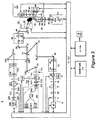
本明細書に開示する方法は、図1に示すシステム2のような光ビームを患者の眼68に投射又は走査するシステムによって実施することができる。システム2は、超高速(UF)光源4(例えば、フェムト秒レーザ)を含む。システム2を使用して、ビームを3次元:x、y、zで患者の眼68に走査することができる。光破壊を焦点(焦点ゾーン)の周りに引き起こすために誘電破壊を生成するために短パルスレーザ光を眼組織に集束させることができ、その結果、組織が光誘導性プラズマの近くで断裂される。この実施形態において、レーザ光の波長は、800nm〜1200nm間で変えることができ、レーザ光のパルス幅は、10fsから10000fsまで変えることができる。パルス繰返し周波数も、10kHzから500kHzまで変えることができる。非ターゲット組織の想定外の損傷に関する安全限界により、繰返し数及びパルスエネルギに関する上限値が抑制され、更に、閾値エネルギ、手順を完了する時間、及び安定性により、パルスエネルギ及び繰返し数の下限値が抑制される。眼68における及び特に眼の水晶体69及び前嚢内の被集束点のピーク電力は、光学破壊を生成してプラズマ介在融除処理を開始するのに十分である。生体組織内の線形光吸収及び散乱が近赤外線波長のために低減されるので、近赤外線波長が多くの実施形態に使用されるが、多くの代替実施形態は、可視光、紫外線、又は赤外光エネルギの1つ又はそれよりも多くを含む。非限定的な例として、レーザ4は、100kHzの繰返し数で500fsパルスを1〜20マイクロジュール範囲で個々のパルスエネルギを生成する繰返しパルス1035nmデバイスとすることができる。一般的に、あらゆる適切なパラメータを有するあらゆる適切なレーザを使用することができる。そのような適切なシステムの例は、Blumenkranzらの名の下で「3次元水晶体セグメント化における水晶体及び嚢パターン化プラズマ介在レーザ穿孔方法及び装置」という名称の米国特許出願第11/328,970号明細書、同号第2006/0195076号に説明されており、この開示内容全体は、引用によって本明細書に組み込まれている。本明細書に説明する実施形態による組合せに適する紫外レーザの実施形態は、Schueleらの名の下で「眼組織及び眼内レンズを修正する方法及びシステム」という名称の米国特許出願第12/987069号明細書、同第2011/0172649号に説明されており、この開示内容全体が、引用によって本明細書に組み込まれている。
The methods disclosed herein may be implemented by a system that projects or scans a light beam, such as
レーザ4は、光ビーム6を作成するために入力及び出力デバイス302を通して制御電子機器300によって制御される。制御電子機器300は、コンピュータ、マイクロコントローラのようなプロセッサを含むことができる。この例では、コントローラ300は、システム全体を制御し、データは、入力及び出力デバイスIO302を通して移動される。グラフィカルユーザインタフェースGUI304は、システム作動パラメータ、プロセスユーザ入力(UI)306を設定して、目の構造体の画像のような収集された情報を表示するのに使用することができる。GUI304及びUI306は、公知のコンピュータシステムの構成要素、例えば、ディスプレイ、タッチスクリーンディスプレイ、キーボード、ポインタ、又はマウスのうちの例えば1つ又はそれよりも多くを含むことができる。例えば、制御電子機器は、コンピュータシステムの1つ又はそれよりも多くのプロセッサを含むことができる。
The
制御電子機器300は、多くの方法のうちの1つ又はそれよりも多くで構成することができ、かつ実施されるコンピュータプログラムの命令を有する有形媒体を有するプロセッサを含むことができる。多くの実施形態において、有形媒体は、実施されるコンピュータ可読媒体の命令を有するコンピュータ可読メモリを含む。これに代えて又は組み合わせで、制御電子機器は、フィールドプログラマブルゲートアレイが本明細書に説明するように1つ又はそれよりも多くの命令を実行するようにゲートアレイ、プログラマブルゲートアレイのようなアレイ論理部を含むことができる。有形媒体の命令は、制御電子機器のプロセッサによって実行することができる。
The
生成されたUF光ビーム6は、患者の眼68の方向に進んで、1/2位相差板8及び直線偏光子10を通過する。ビームの偏光状態は、望ましい光量がUFビーム6の可変減衰器の役目を協働して果たす1/2位相差板8及び直線偏光子10を通過するように調節することができる。更に、直線偏光子10の向きにより、ビーム結合器34に入射する入射光偏光状態が決まり、その結果、ビーム結合器34収量が最適化される。
The generated UF light beam 6 travels in the direction of the patient's
UF光ビーム6は、システム制御式シャッター12、開口14、及びピックオフデバイス16を通って進む。システム制御式シャッター12は、レーザのオン/オフ制御を手順及び安全上の理由から保証する。開口14は、UF光ビーム6の有効外径を設定し、ピックオフデバイス16は、得られたビームをモニタする。ピックオフデバイス16は、部分反射ミラー20と検出器18とを含む。パルスエネルギ、平均電力、又は組合せは、検出器18を使用して測定することができる。検出器18からの出力は、減衰のために1/2位相差板8へのフィードバックに、及びシステム制御式シャッター12が開状態又は閉状態か否かを確かめるために使用することができる。更に、システム制御式シャッター12は、冗長状態検出を行うために位置センサを有することができる。
The UF light beam 6 travels through the system controlled
ビームは、ビーム直径、発散、真円度、及び非点収差のようなビームパラメータを修正することができるビーム調整段22を通過する。この例示的な例では、ビーム調整段22は、意図するビームサイズ及び平行化をもたらすために球面光学器械24、26で構成された2要素ビーム拡大テレスコープを含む。ここで図示していないが、アナモフィック又は他の光学系を、望ましいビームパラメータをもたらすのに使用することができる。これらのビームパラメータを決定するのに使用されるファクタには、レーザの出力ビームパラメータ、システムの全体的な倍率、及び治療位置での望ましい開口数(NA)が挙げられる。更に、ビーム調整段22は、望ましい位置(例えば、以下に説明する2軸走査デバイス50間の中心位置)までの開口14を撮像するのに使用することができる。本方法では、光に開口14を通過させる光量は、光に走査システムを通過させるように保証される。ピックオフデバイス16は、従って、使用可能な光の確実な対策である。
The beam passes through a
ビーム調整段22を出た後に、ビーム6は、折り返しミラー28、30、32から反射する。これらのミラーは、アラインメント目的に対して調節可能とすることができる。ビーム6は、次に、ビーム結合器34に入射する。ビーム結合器34は、UFビーム6を反射する(かつ撮像ビーム、この例示的な事例では光干渉断層撮影(OCT)ビーム114、及び以下に説明する照準202ビームの両方を透過する)。効率的なビーム結合器作動のために、入射角は、45°未満に保たれ、ビームの偏光は、可能であれば一定であることが好ましい。UFビーム6に関して、直線偏光子10の向きによって一定の偏光がもたらされる。この非限定的な例においてOCTが画像診断法として使用されるが、Purkinje撮像、Scheimpflug撮像、共焦点又は非線形光学顕微鏡法、蛍光撮像、超音波、立体照明、ステレオ撮像のような他の手法、又は他の公知の眼科又は医用画像診断法及び/又はその組合せを使用することができる。
After exiting the
ビーム結合器34の後に、ビーム6は、z調節器又はZ走査デバイス40へ進む。この例示的な例では、z調節器40は、2つのレンズ群42、44(各レンズ群は、1つ又はそれよりも多くのレンズを含む)を有するガリレオテレスコープを含む。レンズ群42は、テレスコープの平行化位置の周りにz軸に沿って移動する。このようにして、患者の眼68内のスポットの焦点位置は、図示のようにz軸に沿って移動する。一般的に、一定の比例関係がレンズ42の作動と焦点の作動の間に存在する。この場合に、z調節テレスコープは、ほぼ2倍のビーム拡大比率及び1:1のレンズ42の動き:焦点の移動の関係を有する。これに代えて、レンズ群44は、z調節及び走査を起動させるためにz軸に沿って移動することができる。z調節器40は、眼68の治療のためのz走査デバイスである。このデバイスは、システムによって自動的かつ動的に制御され、独立するか又は次に説明するX−Y走査デバイスと相互作用するように選択することができる。ミラー36、38は、光軸をz調節器40の軸と位置合わせさせるのに使用することができる。
After the
z調節器40を通過した後に、ビーム6は、ミラー46、48によってx−y走査デバイス50に向けられる。ミラー46、48は、アラインメント目的に対して調節可能とすることができる。X−Y走査は、好ましくは、制御電子機器300の制御下の2つのミラー52、54を使用する走査デバイス50によって達成され、この制御電子機器は、モータ、検流計、又はあらゆる他の公知の光移動デバイスを使用して直交方向に回転する。ミラー52、54は、以下に説明する対物レンズ58及び接触レンズ66組合せのテレセントリック位置の近くに位置付けられる。ミラー52、54を傾かせると、ビーム6の得られる方向が変化し、横方向変位が、患者の眼68に位置付けたれたUF焦点の平面に発生する。対物レンズ58は、図示のように、複合多要素レンズ要素とすることができ、かつレンズ60、62及び64によって表すことができる。対物レンズ58の複合性は、走査野サイズ、集束スポットサイズ、対物レンズ58の近位側及び遠位側の両方の利用可能な作動距離、並びに収差制御の量によって決定付けられることになる。直径15mmの入力ビームサイズで10mmの走査野にわたって10μmのスポットサイズを生成する焦点距離60mmのf−θ対物レンズ58がその例である。これに代えて、走査デバイス50によるx−y走査はまた、入力及び出力デバイス302を通して制御電子機器300によって制御することができる1つ又はそれよりも多くの移動可能な光学器械(例えば、レンズ、回折格子)を使用することによって達成することができる。
After passing through the
制御電子機器300の制御下の走査デバイス50は、照準及び治療走査パターンを自動的に生成することができる。そのようなパターンは、単一光点、複数の光点、光の連続パターン、光の複数の連続パターン、及び/又はこれらのあらゆる組合せで構成することができる。更に、(以下に説明する照準ビーム202を使用する)照準パターンは、(光ビーム6を使用する)治療パターンと同一である必要はないが、治療光が患者安全のために確実に望ましいターゲット区域のみに送出されるように境界を少なくとも定めることが好ましい。これは、例えば、照準パターンに意図する治療パターンの外形を提供させることによって行うことができる。このようにして、治療パターンの空間範囲は、個々の点自体の正確な位置とまではいかないが、ユーザに分るようにすることができ、走査は、従って、速度、効率、及び精度に対して最適化することができる。照準パターンはまた、ユーザに対する視認性を高めるために明滅で知覚させることができる。
The
あらゆる適切な眼のためのレンズとすることができる任意的な接触レンズ66は、眼の位置を安定させる一助としながら光ビーム6を患者の眼68に更に集束するのを補助するために使用することができる。光ビーム6の位置決め及び特性及び/又は光ビーム6が眼68の上に形成する走査パターンは、更に、患者及び/又は光学系を位置決めするためにジョイスティックのような入力デバイス、又はあらゆる他の適切なユーザ入力デバイス(例えば、GUI304)の使用によって制御することができる。
An optional contact lens 66, which can be a lens for any suitable eye, is used to help further focus the light beam 6 on the patient's
UFレーザ4及び制御電子機器300は、眼68におけるターゲット構造体をターゲットとして光ビーム6が適切な場合に確実に集束されてターゲット以外の組織を誤って損傷させないように設定することができる。上述したもの又は超音波のような本明細書に説明する画像診断法及び技術は、位置を決定して2D及び3Dパターン化を含むレーザ集束法の正確化をもたらすために水晶体及び水晶体嚢の厚みを測定するために使用することができる。レーザ集束はまた、照準ビームの直接観測、又は上述したもののような他の公知の眼科又は医用画像診断法及び/又はその組合せを含む1つ又はそれよりも多くの方法を使用して達成することができる。図1の実施形態において、OCTデバイス100を説明するが、他の治療法も本発明の範囲である。眼のOCT走査は、前後水晶体嚢の軸線方向の位置、白内障核の境界、並びに前眼房の深さに関する情報を提供することになる。この情報は、次に、制御電子機器300に取り込まれ、その後のレーザ支援型外科的手技をプログラム及び制御するのに使用される。この情報はまた、例えば、取りわけ、水晶体嚢切断及び水晶体皮質及び核のセグメント化に使用される焦点面の軸線方向の上限及び下限及び水晶体嚢の厚みのような手順に関連する広範なパラメータを決定するのに使用することができる。
The
図1のOCTデバイス100は、基準アーム106及びサンプルアーム110にファイバ結合器104によって分割される広帯域又は掃引光源102を含む。基準アーム106は、適切な分散及び経路長補償と共に基準反射を含むモジュール108を含む。OCTデバイス100のサンプルアーム110は、UFレーザシステムの残りとの接続部として機能する出力コネクタ112を有する。基準及びサンプルアーム106、110の両方からの戻り信号は、次に、時間領域検出技術、周波数検出技術、又は単一点検出技術を使用する検出デバイス128に結合器104によって向けられる。図1では、周波数領域技術は、830nmのOCT波長及び100nmの帯域幅と共に使用される。
The
コネクタ112を出た後に、OCTビーム114は、レンズ116を使用して平行化される。平行化されたOCTビーム114のサイズは、水晶体116の焦点距離に依存する。ビーム114のサイズは、眼内の焦点での望ましいNA及び眼68に至るビーム列の倍率によって決定付けられる。通常は、OCTビーム114は、焦点面ではUF光ビーム6ほどの高いNAを必要とせず、従って、OCTビーム114は、直径がビーム結合器34の位置でのUF光ビーム6よりも小さい。平行化レンズ116の後には、眼でのOCTビーム114の得られるNAを更に修正する絞り118がある。開口118の直径は、ターゲット組織に入射するOCT光及び戻り信号の強度を最適化するように選択される。アクティブ又は動的とすることができる偏光制御要素120が、偏光状態の変化を補償するのに使用される。偏光状態の変化は、例えば、角膜複屈折の個々の差によって誘発される場合がある。ミラー122、124は、次に、OCTビーム114をビーム結合器126、34の方向に向けるのに使用される。ミラー122、124は、アラインメントに対して、及び特にビーム結合器34の後のUF光ビーム6へのOCTビーム114の重畳に対して調節可能とすることができる。同様に、ビーム結合器126は、以下に説明するように、OCTビーム114を照準ビーム202と結合するのに使用される。
After exiting
OCTビーム114は、ビーム結合器34の後にUF光ビーム6と結合された状態で、系の残りを通るUF光ビーム6と同じ光路に従う。このようにして、OCTビーム114は、UF光ビーム6の位置を示している。次に、OCTビーム114は、z走査40及びx−y走査50デバイスを通過し、次に、対物レンズ58、接触レンズ66を通過して眼68に入る。眼の中の構造体からの反射及び散乱は、光学系を通ってコネクタ112に入り、結合器104を通ってOCT検出器128に戻る戻りビームをもたらす。これらの戻り後方反射は、UF光ビーム6焦点位置のX、Y、及びZにおける位置に関して次にシステムによって解釈されるOCT信号をもたらす。
The
OCTデバイス100は、基準及びサンプルアーム間の光路長の差を測定する原理で作用する。従って、OCTビーム114をz調節器40に通しても、OCTシステム100のz範囲は拡張せず、その理由は、光路長がレンズ群42の移動の関数として変わらないからである。OCTシステム100は、検出方式に関連する固有のz範囲を有し、周波数領域検出の場合に、この範囲は、具体的には分光計及び基準アーム106の位置に関連する。図1に使用されたOCTシステム100の場合に、z範囲は、水環境においてほぼ1〜2mmである。この範囲を少なくとも4mmに拡張することは、OCTシステム100内の基準アームの光路長の調節を伴っている。サンプルアームにおいてOCTビーム114をz調節器40のz走査に通すことは、OCT信号強度の最適化を可能にする。これは、OCTシステム100の基準アーム106内の光路を相応に増大させることによって拡張された光学光路長に適合させながらOCTビーム114をターゲット構造体上へ集束させることによって達成される。
The
液浸指標、屈折、及び有色及び単色両方の収差のような影響に起因するUFフォーカスデバイスに関するOCT測定値の基本的な差のために、OCT信号をUFビーム焦点位置に関して解析する際には注意しなければならない。X、Y、及びZの関数としての較正又は位置合わせ手順が、OCT信号情報をUF焦点位置に、更には相対から絶対までの次元量に適合させるために行われるべきである。 Care should be taken when analyzing OCT signals with respect to UF beam focus position due to fundamental differences in OCT measurements for UF focus devices due to effects such as immersion index, refraction, and both colored and monochromatic aberrations Must. A calibration or alignment procedure as a function of X, Y, and Z should be performed in order to adapt the OCT signal information to the UF focal position and also to relative to absolute dimensional quantities.
照準ビームの観測結果はまた、ユーザがUFレーザ焦点に向けるのを容易にするために使用することができる。これに加えて、赤外線OCTビーム及びUF光ビームの代わりの肉眼に見える照準ビームが、照準ビームが赤外線ビームパラメータを正確に表すことを条件としてアラインメントに役に立つことができる。照準サブシステム200が、図1に示す構成に使用される。照準ビーム202は、633nmの波長で作動するヘリウムネオンレーザのような照準ビーム光源201によって生成される。これに代えて、630〜650nmの範囲のレーザダイオードを使用することができる。ヘリウムネオン633nmビームを使用する利点は、その長い干渉長であり、この長い干渉長は、レーザ非等光路干渉計(LUPI)としての照準光路の使用が、例えば、ビーム列の光学品質を測定するのを可能にすることになると考えられる。
The aim beam observations can also be used to facilitate the user to aim at the UF laser focus. In addition, a sighting beam that is visible to the eye instead of the infrared OCT beam and the UF light beam can be useful for alignment, provided that the aiming beam accurately represents the infrared beam parameters. Aiming
照準ビーム光源201が照準ビーム202を生成すると、照準ビーム202は、レンズ204で平行化される。平行化ビームのサイズは、水晶体204の焦点距離に依存する。照準ビーム202のサイズは、眼内の焦点での望ましいNA及び眼68に至るビーム列の倍率によって決定付けられる。通常は照準ビーム202は、焦点面においてUFと同じに近いNAに光ビーム6を有し、従って、照準ビーム202は、ビーム結合器34でUF光ビーム6と類似の直径である。照準ビーム202は、眼のターゲット組織への系アラインメント中にUF光ビーム6の代役を務めることが意図されるので、照準光路の多くは、上述のようにUFパスに似ている。照準ビーム202は、1/2位相差板206及び直線偏光子208を通って先に進む。照準ビーム202の偏光状態は、望ましい光量が偏光子208を通過するように調節することができる。1/2位相差板206及び直線偏光子208は、従って、照準ビーム202の可変減衰器として作用する。更に、偏光子208の向きにより、ビーム結合器126、34に入射する入射光偏光状態が決定され、その結果、偏光状態が固定され、ビーム結合器126、34の収量の最適化が可能である。勿論、固体レーザが照準ビーム光源200として使用される場合に、光出力を調節するために駆動電流を変えることができる。
When the aiming
照準ビーム202は、システム制御式シャッター210及び絞り212を通って先に進む。システム制御式シャッター210は、照準ビーム202のオン/オフ制御を提供する。絞り212は、照準ビーム202に対して有効外径を設定して適切に調節することができる。眼での照準ビーム202の出力を測定する較正手順を使用して、照準ビーム202の減衰を偏光子206の制御を通して設定することができる。
Aiming
次に、照準ビーム202は、ビーム調整デバイス214を通過する。ビーム直径、発散、真円度、及び非点収差のようなビームパラメータは、1つ又はそれよりも多くの公知のビーム調節光学器械を使用して修正することができる。光ファイバから現れる照準ビーム202の場合に、ビーム調整デバイス214は、意図するビームサイズ及び平行化をもたらすために2つの光学器械216、218を有するビーム拡大テレスコープを単に含むことができる。平行化の程度のような照準ビームパラメータを決定するのに使用される最終的な要素は、UF光ビーム6及び照準ビーム202を眼68の位置で適合させるのに必要であるものによって決定付けられる。色収差は、ビーム調整デバイス214の適切な調節によって考慮に入れることができる。更に、光学系214は、絞り212を絞り14の共役位置のような望ましい位置に撮像するのに使用される。
The aiming
照準ビーム202は、次に、折り返しミラー220、222から反射し、折り返しミラーは、ビーム結合器34後のUF光ビーム6に対するアラインメント位置合わせに対して調節可能であることが好ましい。照準ビーム202は、次に、照準ビーム202がOCTビーム114と結合されるビーム結合器126に入射する。ビーム結合器126は、照準ビーム202を反射し、OCTビーム114を透過し、これは、両方の波長範囲でのビーム結合機能の効率的な作動を可能にする。これに代えて、ビーム結合器126の透過機能及び反射機能を逆転することができ、構成を反対にすることができる。ビーム結合器126の後に、照準ビーム202は、OCTビーム114と共にビーム結合器34によってUF光ビーム6と結合される。
The aiming
眼68上又は眼内のターゲット組織を撮像するデバイスが、撮像システム71として図1に概略的に示されている。撮像システム71は、ターゲット組織の画像を作成するカメラ74及び照明光源86を含む。撮像システム71は、予め定義された構造体の周りに又は構造体内に中心があるパターンを供給する制御電子機器300によって使用することができる画像を収集する。照明光源86は、ほぼ広帯域及びインコヒーレントである。例えば、光源86は、図示のように複数のLEDを含むことができる。照明光源86の波長は、好ましくは700nm〜750nmの範囲であるが、ビーム結合器5によって受け入れられるものとすることができ、ビーム結合器は、観察光をUF光ビーム6及び照準ビーム202のビーム経路と結合する(ビーム結合器56は、観察波長を反射し、一方、OCT及びUF波長を透過する)。ビーム結合器56は、照準ビーム202が表示カメラ74に見えるように照準波長を部分的に透過することができる。光源86の前の任意的な偏光要素84は、直線偏光子、1/4位相差板、1/2位相差板、又はあらゆる組合せとすることができ、信号を最適化するのに使用される。近赤外線形波長によって生成されるような偽カラー画像は、許容可能である。
A device for imaging a target tissue on or in the
光源86からの照明光は、UF光ビーム6及び照準ビーム202と同じ対物レンズ58及び接触レンズ66で眼の方向に向けられる。眼68の様々な構造体から反射及び散乱した光は、同じレンズ58、66によって集束されてビーム結合器56の方向に向けられる。ビーム結合器56で、戻り光は、ビーム結合器56及びミラー82を通して観察光路に、及び表示カメラ74上に向けられる。表示カメラ74は、例えば、適切にサイズ設定されたフォーマットのあらゆるシリコン系検出器アレイであるが、これに限定することはできない。映像レンズ76が、画像をカメラの検出器アレイの上に形成し、一方、光学器械80、78が、それぞれ、偏光制御及び波長フィルタリングを提供する。絞り又は虹彩81が、撮像NA、従って、焦点深度及び被写界深度の制御を提供する。小さい絞りが、患者精密検査手順を容易にする大きい被写界深度という利点をもたらす。これに代えて、照明経路及びカメラ経路を切り換えることができる。更に、照準光源200に、直接に可視ではなくて撮像システム71で捕捉及び表示することができる赤外光を射出させることができる。
Illumination light from the light source 86 is directed toward the eye by the same
粗い調節位置合わせが、通常は接触レンズ66が眼68の角膜と接触する時にターゲット構造体がシステムのX−Y走査の捕捉範囲にあるように必要とされる。従って、システムが接触状態(すなわち、患者の眼68と接触レンズ66との接触)に接近する時に好ましくは患者の動きを考慮する精密検査手順が好ましい。この視認システム71は、接触レンズ66が眼68と接触する前に患者の眼68及び他の顕著な特徴が見えるように焦点深度が十分に大きいように構成される。
Coarse adjustment alignment is usually required so that the target structure is in the capture range of the XY scan of the system when the contact lens 66 contacts the cornea of the
動き制御システム70は、システム2全体に一体化されて、接触レンズ66と眼68との正確及び確実な接触をもたらすために、患者、システム2、又はその要素、又は両方を移動することができることが好ましい。更に、真空吸引サブシステム及びフランジをシステム2に組み込むことができ、眼68を安定化させるために使用することができる。接触レンズ66を通じたシステム2との眼68のアラインメントは、撮像システム71の出力をモニタしながら達成することができ、IO302を通して制御電子機器300によって電子的に撮像システム71によって生成された画像を解析することによって手動で又は自動的に行うことができる。また、力及び/又は圧力センサフィードバックを使用して、接触を見分け、並びに真空サブシステムを始動することができる。代替患者インタフェースは、米国特許出願第13/225,373号明細書に説明されているように使用することができ、この特許は、引用によって本明細書に組み込まれている。
The
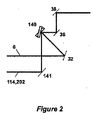
代替ビーム結合構成を図2の代替実施形態に示している。例えば、図1の受動ビーム結合器34は、図2に示すように能動結合器140と交換することができる。図示のように、能動ビーム結合器140は、ガルバノ走査ミラーのような移動式又は動的に制御された要素とすることができる。能動結合器140は、一度に1つずつUF光ビーム6又は結合された照準及びOCTビーム202,114を走査デバイス50の方向にかつ最終的には眼68の方向に向けるために角度的向きを変える。能動結合技術の利点は、受動ビーム結合器を使用して類似の波長範囲又は偏光状態を有するビームを結合するという問題点を回避するということである。この機能は、時間的に同時のビームを有する機能とトレードオフされ、潜在的に劣る精度及び精度は、能動ビーム結合器140の位置決め公差に起因する。
An alternative beam combining configuration is shown in the alternative embodiment of FIG. For example, the
別の代替実施形態を図3に示しており、図1のそれに類似であるが、OCT100への代替手法を利用する。図3では、OCT101は、基準アーム106が基準アーム132に取って代わられていることを除き、図1のOCT100と同じである。この自由空間OCT基準アーム132は、水晶体116の後にビームスプリッタ130を含むことによって達成される。基準ビーム132は、次に、偏光制御要素134を通り、次に、基準戻りモジュール136上へ進む。基準戻りモジュール136は、適切な分散及び光路長調節及び補償要素を含み、サンプル信号との干渉のために適切な基準信号を生成する。OCT101のサンプルアームが、ここで、ビームスプリッタ130の後に出てくる。この自由空間構成の潜在的な利点には、基準及びサンプルアームの別々の偏光制御及び維持が挙げられる。OCT101の繊維系ビームスプリッタ104はまた、繊維系循環器に取って代わることができる。これに代えて、OCT検出器128及びビームスプリッタ130は、両方とも、基準戻りモジュール136とは対照的に一緒に移動されることがある。
Another alternative embodiment is shown in FIG. 3 and is similar to that of FIG. 1 but utilizes an alternative approach to
図4は、OCTビーム114及びUF光ビーム6を結合する別の代替実施形態を示している。図4では、OCT156(OCT100又は101の構成のいずれかを含むことができる)は、OCT156によって出力されたOCTビーム154がビーム結合器152を使用するz走査デバイス40の後にUF光ビーム6に結合されるように構成される。このようにして、OCTビーム154は、z走査デバイス40を使用することを回避する。それによってOCT156を一部の場合に簡単にビームに折り込んで作動安定化のために光路長を短縮することができる。このOCT構成は、図1に関して上述したように信号戻り記号強度の最適化の代償である。時間及び周波数領域手法、単一及び二重ビーム方法、掃引光源などを含む多くの可能性は、米国特許第5,748,898号明細書、米国特許第5,748,352号明細書、米国特許第5,459,570号明細書、米国特許第6,111,645号明細書、及び米国特許第6,053,613号明細書に説明されているようにOCT干渉計の構成に対して存在する(これらの特許の開示内容は、参照によって本明細書に組み込まれている)。
FIG. 4 shows another alternative embodiment for combining the
システム2は、嚢の表面の位置を識別して、光ビーム6が望ましい開口部の全ての点で水晶体嚢上で集束されることを保証するように設定することができる。例えば、Purkinje撮像、Scheimpflug撮像、共焦点又は非線形光学顕微鏡法、蛍光撮像、超音波、立体照明、ステレオ撮像、又は他の公知の眼科又は医用画像診断法及び/又はその組合せのような光干渉断層撮影(OCT)のような本明細書に説明する画像診断法及び技術を使用して、2D及び3Dパターン化を含むレーザ集束法の正確化をもたらすために水晶体及び水晶体嚢の形状、幾何学的形状、周囲、境界、及び/又は3次元の位置を決定することができる。レーザ集束はまた、以下に限定されるものではないが、照準ビームの直接観測、又は先に定義したものなどのような他の公知の眼科又は医用画像診断法及び/又はその組合せを含む1つ又はそれよりも多くの方法を使用して達成することができる。
The
前眼房及び水晶体の光学撮像は、切断のためのパターンを生成するのに使用される同じレーザ及び/又は同じ走査デバイスを使用して水晶体に行うことができる。この走査は、前後水晶体嚢、白内障核の境界、並びに前眼房の深さの軸線方向の位置及び形状(及び更には厚み)に関する情報を提供することになる。この情報は、次に、レーザ3D走査システム取り込むことができ、又は前眼房の3次元モデル/表現/画像及び眼のレンズを生成するのに使用することができ、かつ外科的手技に使用されたパターンを定めるために使用することができる。 Optical imaging of the anterior chamber and the lens can be performed on the lens using the same laser and / or the same scanning device that is used to generate the pattern for cutting. This scan will provide information regarding the axial position and shape (and even thickness) of the anterior and posterior lens capsule, the boundary of the cataract nucleus, and the depth of the anterior chamber. This information can then be captured by a laser 3D scanning system, or used to generate a three-dimensional model / representation / image of the anterior chamber and an eye lens, and used for surgical procedures. Can be used to define different patterns.
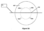
上述のシステムは、眼の水晶体の嚢を切開して固定嚢切開を生成するのに使用することができる。一例は、図5Aに示すIOL上で相補型固定特徴部と嵌合するのに使用することができるより大きい嚢切開の周りに周方向に規則的な間隔に配置された水晶体嚢内の4つの固定嚢切開のアレイである。この例では、嚢402を上述のシステムを使用して切開して固定嚢切開432A〜432Dを作成する。これらのマイクロフェムト切開は、中心嚢切開400周囲の周りに配置される。中心嚢切開400は、本発明を実施するのに要求されず、IOL440が、中心嚢切開400が先在する既存のIOL(図示せず)の上方に又は中心嚢切開400が白内障手術中に水晶体を除去する器具使用ためのアクセスをもたらすために従来の方法に使用される場合嚢自体内へ移植される事例の非限定的な例として示している。
The system described above can be used to incise the lens capsule of the eye to create a fixed capsulotomy. One example is four fixations in a capsular bag spaced circumferentially around a larger capsulotomy that can be used to mate with complementary fixation features on the IOL shown in FIG. 5A. An array of capsulotomy. In this example, the
多くの実施形態において、眼は、収差軸405に沿って延びる収差を含む。収差軸は、例えば、非点収差及び高次収差のような眼の収差を説明するのに適切な多くの軸の1つ又はそれよりも多くを含むことができる。多くの実施形態において、収差軸405は、眼の横軸に沿って又は眼の垂直軸に沿って延びることになる。非点収差に関して、第1の軸は、第1の方向に延びることができ、第2の軸は、第1の方向に垂直な第2の方向に延びることができる。多くの実施形態において、収差軸405は、眼の横軸から離れるようにかつ眼の垂直軸から離れるように延びることになる。
In many embodiments, the eye includes an aberration that extends along the
図5Bは、固定嚢切開432A〜432Dを通して拘束されるように構成されたIOL440を示している。この非限定的な例では、IOL440は、固定嚢切開432A〜432Dと係合するように構成されたアンカー442、並びにストラット450を伴って構成される。ストラット450は、規定の距離をIOL440と嚢402の間に維持することが意図される。これを、「後発白内障」としても公知である後嚢不透明化に関して以下の節でより詳細に説明する。固定嚢切開は、手によって確実に作成されるには小さすぎる場合がある。同様に、固定嚢切開の必要な配置は、非常に正確とすることができる。患者の眼の水晶体嚢に対するIOLの改善した配置をもたらすそのような嵌合する固定嚢切開及びIOL固定特徴部を使用する無数の可能性がある。欧州特許出願第EPP16613A−100927号明細書では、類似のIOLを開示しており、これは、引用によって本明細書に含まれる。
FIG. 5B shows an
多くの実施形態において、IOL440は、眼の収差及び収差矯正軸445を矯正する形状を含む。収差矯正軸445は、アンカー442に関連して、例えば、アンカー442に対して予め決められたアラインメントで位置合わせすることができる。アンカー442は、眼の非点収差又は高次収差のうちの1つ又はそれよりも多くのような眼の収差を治療するために収差矯正軸445を収差軸405と位置合わせするように位置付けることができる。
In many embodiments, the
図6A及び図6Bは、マイクロフェムト切開432を使用して図5BのIOL440をアンカー442によって水晶体嚢402内に固定する上述の実施形態のより解剖学的な詳細を示している。
FIGS. 6A and 6B show more anatomical details of the above-described embodiment using a
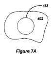
固定嚢切開は、前出例及び更に改めて図7Aに示すように、円形である必要はない。非限定的な例として、図7A〜図7Cは、使用することができる数個の有用な固定嚢切開形状を示している。一般的に、あらゆる適切に成形された固定嚢切開を使用することができる。図7B及び図7Cは、楕円形及び矩形の固定嚢切開形状の周囲の2つの例示的な代替構成を示している。楕円形及び/又は矩形固定嚢切開の成形された周囲を上述のボタン穴概念に使用することができる。図7B及び図7Cに示す周囲は、長短両方の縁を含む。 The fixed sac incision need not be circular, as in the previous example and again shown in FIG. 7A. By way of non-limiting example, FIGS. 7A-7C illustrate several useful fixed capsulotomy shapes that can be used. In general, any suitably shaped fixed capsulotomy can be used. FIGS. 7B and 7C show two exemplary alternative configurations around an elliptical and rectangular fixed capsulotomy shape. The shaped perimeter of an oval and / or rectangular fixed sac incision can be used for the buttonhole concept described above. The perimeter shown in FIGS. 7B and 7C includes both long and short edges.
各アンカーの先端は、係合するとアンカーを捕捉してアンカーを定位置に保持するように対応する嚢切開に挿入して押し通すことができる。従って、アンカーの先端は、固定嚢切開のボタン穴切開よりも全体的に大きいものであるべきである。これは、ボタンを保持するボタン穴と類似と考えることができる。これに代えて、ボタン穴嚢切開は、単一直線切開を使用して構成することができる。そのような直線切開は、この切開が移植されるIOLの適合する支柱を示す円に正接するか又はほぼ正接するように作ることができる。従って、IOLは、切開が移植されるIOLの支柱の位置を示す円に多かれ少なかれ垂直な時に当て嵌まるように、支柱が多かれ少なかれ定位置に完全にある必要があるということではなく、個々に各支柱を挿入することによって埋め込むことができる。 The tip of each anchor can be inserted and pushed through the corresponding capsulotomy to capture the anchor when engaged and hold the anchor in place. Thus, the anchor tip should be generally larger than the fixed sac incision buttonhole incision. This can be considered similar to a buttonhole holding a button. Alternatively, the buttonhole sac incision can be constructed using a single straight incision. Such a linear incision can be made so that the incision is tangent or nearly tangent to the circle that indicates the compatible post of the IOL to be implanted. Thus, the IOL does not require that the struts be more or less completely in place, so that the incision fits more or less perpendicular to the circle indicating the position of the IOL struts to be implanted. It can be embedded by inserting a post.
切開はまた、切開が名目上は直線であって丸みを帯びた縁部を含む「骨形状の」切開を形成するように作ることができる。同様に、涙滴形状の又は円形点涙滴形状の切開を構成することができる。 The incision can also be made so that the incision is nominally straight and forms a “bone-shaped” incision with rounded edges. Similarly, a teardrop-shaped or circular teardrop-shaped incision can be constructed.
更に別の代替実施形態において、小さい嚢切開を矩形ではなくて実質的に正方形であるように作ることができる。添付図面には図示していないが、実質的に直線の縁部を含む小さい嚢切開のコーナを丸みをもたせて鋭いコーナでの歪み集中に起因する嚢切開拡張の危険性を最小にすることができる。特に滑らかに丸みを帯びた縁部を有するそのような小さい嚢切開を作成するのは、実際的には手動で行うのは不可能である。 In yet another alternative embodiment, the small capsulotomy can be made to be substantially square rather than rectangular. Although not shown in the accompanying drawings, a small capsulotomy corner that includes a substantially straight edge may be rounded to minimize the risk of capsulotomy expansion due to strain concentration at the sharp corner. it can. Creating such a small capsulotomy with a particularly smoothly rounded edge is practically impossible to do manually.
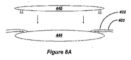
図8A及び図8Bは、移植されるIOL440が既存の眼球レンズ444の上方に置かれる代替実施形態を示している。これは、代替的に「ピギーパック」と本明細書で呼ばれ、既存の眼球レンズ444(本来の水晶体又は人工インプラント)の除去がもたらされない場合には特に有用である。そのような追加のレンズ440の移植は、若年性白内障のような特定の場合に又は患者の屈折が時間と共に認め得るほどに変わる他の状況において望ましい場合がある。そのような場合に、たとえ眼が侵襲をうけるべきであるとしても、既存のインプラント444の除去に関連付けられた危険性は、IOL440を前眼房において既存の水晶体444上に埋め込むことによって回避される。そのようなIOLは、患者の光学系の均衡を改善するように構成することができる。これは、それぞれ、正及び負の球面レンズのような光学器械の導入によって遠視及び近眼の場合に達成することができる。円柱レンズ、光学くさび、及び屈折率勾配材料のような円環要素も、非点収差を矯正するために、更に、コマ収差のような高次収差に対処するのにも使用することができる。
FIGS. 8A and 8B show an alternative embodiment in which the implanted
更に、与えられた配置精度により、多くの収差を矯正するために光学器械を患者の眼に埋め込むことができる。例えば、患者の屈折は、カスタマイズされた光学インプラントを設計することができるように、波面測定又は他の適切な手段、及び決定される正視をもたらすのに要求される光学矯正によって決定することができる。便宜上、光学インプラントをIOLと呼ぶが、光学インプラントは、従来のレンズである必要はない。このインプラント(IOL)は、次に、移植の向きが明確であるように製作することができる。これは、図9A〜図9Dに示すようにIOL向きが「鍵結合」又は「クロック結合」であるようにアンカー及び嵌合する固定嚢切開の回転非対称の構成を使用して達成することができる。従って、IOL440は、眼の嚢内に置くことができ、嚢が眼の非点収差軸に対してIOLを回転方向に置くようになっている。そのようなクロック結合は、図9C及び図9Dに示すようにマイクロフェムト切開432A、432B、432C、434Dのパターンを切開が回転非対称のパターンを形成するように置くことによって達成することができる。この回転非対称のパターンは、IOLの軸が、眼の正しい軸に位置合わせして、例えば、ミスアラインメントで90°又は120°ではないことを保証するのに有用とすることができる。これに代えて、切開パターンは、図9A及び図9Bに示すように回転対称のパターンを形成するように作ることができる。左右対称及び左右非対称のパターンのような類似の案を使用することができる。パターンは、眼の上に中心があるものとすることができる。
Furthermore, with a given placement accuracy, an optical instrument can be implanted in the patient's eye to correct many aberrations. For example, patient refraction can be determined by wavefront measurements or other suitable means, and optical corrections required to provide the determined normal vision so that a customized optical implant can be designed. . For convenience, the optical implant is referred to as an IOL, but the optical implant need not be a conventional lens. This implant (IOL) can then be fabricated so that the orientation of the implant is clear. This can be accomplished using a rotationally asymmetric configuration of a fixed capsulotomy that anchors and mates such that the IOL orientation is “key-coupled” or “clock-coupled” as shown in FIGS. 9A-9D. . Accordingly, the
多くの実施形態において、眼の収差軸405は、IOLの収差矯正軸445に位置合わせする。マイクロフェムト切開432A、432B、432C、434Dのパターンは、水晶体の収差矯正軸445を眼の収差軸405と位置合わせするように嚢上に位置付けることができる。
In many embodiments, the
IOLの回転の向き、あるいは、眼の幾何学的軸又は眼の光軸の周りの回転指標付けの提供も、パターンが他のマイクロフェムト切開と異なる複数のマイクロフェムト切開の1つを作ることによって行うことができる。それによって眼及び/又は移植されるIOLの非対称軸を識別する機能が得られる。この識別で、外科医は適合する特徴を配置して患者の眼におけるIOLの正しいアラインメントを保証することができる。これらの切開と嵌合するのに使用されるIOLは、その臨床的有用性を改善するために同一ではない支柱と共に製造することができる。 The orientation of the rotation of the IOL, or the provision of rotation indexing around the eye's geometric axis or the optical axis of the eye, can also be made by creating one of a plurality of microfemto incisions whose pattern differs from other micro femto incisions. It can be carried out. This provides the ability to identify the asymmetric axis of the eye and / or the implanted IOL. With this identification , the surgeon can place matching features to ensure correct alignment of the IOL in the patient's eye. The IOL used to mate with these incisions can be manufactured with non-identical struts to improve its clinical utility.
同様に、横方向の位置(すなわち、嚢上のマイクロフェムト切開の外側の位置)を使用して手順の視覚的結果を改善することができる。非対称の瞳又は擬似中心窩の存在は、他の場合に予想されるものとは異なる外側のアラインメントを示すことができる。すなわち、そのような眼の非対称性により、解剖学的組織を単に見ても予知されないIOL位置が発生することになる。本発明のシステム及び方法は、特に解剖学的目印又は他のそのような基準点に対する切開配置をもたらすために一体型の撮像システムが使用される時に解剖学的撮像及びレーザ支援型嚢切開の作成によって得られる精度及び柔軟性によってこれらの異常に対処するのに特に適している。 Similarly, the lateral position (ie, the position outside the microfemto incision on the sac) can be used to improve the visual outcome of the procedure. The presence of an asymmetric pupil or pseudo fovea can indicate an outer alignment that is different from what would otherwise be expected. That is, such asymmetry of the eye results in an IOL position that cannot be predicted simply by looking at the anatomy. The system and method of the present invention creates anatomical imaging and laser-assisted capsulotomy, especially when an integrated imaging system is used to provide an incision placement relative to an anatomical landmark or other such reference point. Is particularly suitable for dealing with these anomalies due to the accuracy and flexibility afforded by.
この概念は、支柱の大半を最低半径方向力の方向に置くことにより、IOLの支柱と係合することを目的とした切開の非対称パターンを誘導することによって嚢収縮の自然な非対称性に対処するように拡張することができる。 This concept addresses the natural asymmetry of capsular contraction by inducing an asymmetric pattern of incision intended to engage the IOL strut by placing most of the strut in the direction of the lowest radial force. Can be extended as
レンズ除去の後の嚢内に残る水晶体上皮細胞(LEC)が問題になることがある。線維芽細胞のような細胞へのLECの分化により、嚢のしわ、折り目、及び不透明度(「後発白内障」)を引き起こす可能性もあり、その結果、後嚢不透明化(PCO)及びIOL中心ずれが発生する可能性がある。後嚢不透明化によって25%よりも多い患者に白内障手術後の最初の5年で視力の低下が発生すると報告されている。手術後の2〜4週で、嚢内の繊維組織の形成が発生することが多く、レンズが後嚢上に押し戻される。従来の正方形の縁部を有するIOLでは、水晶体の後縁部上でのLECの移動に対する機械的な障壁が作成され、正方形の縁部を有する障壁は、中心視野がPCOなしに保たれるように位置付けられる。PCOは、ジクロフェナクナトリウム、ケトロラクトロメタミンの非限定的な例のような治療薬、及び細胞毒性のLEC特異遺伝子の放出を通してPCOと戦うために、本明細書に説明するIOLデバイスを使用して2つの明確に異なる方法で、及び埋め込まれた薬剤溶出デバイス(プラグ、又はペレットのような)を使用して第3の方法で回避することができる。 Lens epithelial cells (LECs) remaining in the sac after lens removal may be a problem. Differentiation of LECs into cells such as fibroblasts can also cause sac wrinkles, folds, and opacity ("post cataract"), resulting in posterior capsule opacification (PCO) and IOL misalignment May occur. It has been reported that more than 25% of patients with posterior capsule opacification experience visual loss in the first 5 years after cataract surgery. Two to four weeks after surgery, fiber tissue formation in the sac often occurs and the lens is pushed back onto the posterior capsule. In conventional IOLs with square edges, a mechanical barrier is created for movement of the LEC on the posterior edge of the lens so that the central field of view remains without the PCO. Positioned on. PCO uses the IOL devices described herein to fight PCO through the release of diclofenac sodium, therapeutic agents such as non-limiting examples of ketorolac tromethamine, and cytotoxic LEC-specific genes. It can be avoided in the third method in two distinctly different ways and using an embedded drug eluting device (such as a plug or pellet).
時間と共にIOLを変位させて患者の屈折矯正を変更する役目をする嚢における不透明化及び機械的な不適合部の両方を引き起こす水晶体上皮細胞の増殖を防止するための嚢の緊密な密封は、シールをレンズが各固定嚢切開の周りに、及びまた嚢上でより大きい中心嚢切開の周りに形成するように嵌合するIOLを製作することによって達成することができる。第2の手法は、問題のあるサイトカイン及び他の作用物質を希釈することによって上皮細胞増殖及び/又は分化を増加する危険性を最小にするために前眼房と流体連通する開放状態の嚢を維持することである。 Close sealing of the sac to prevent lens epithelial cell proliferation that causes both opacification and mechanical incompatibility in the sac, which serves to change the patient's refractive correction by displacing the IOL over time, This can be accomplished by making an IOL that fits so that the lens forms around each fixed capsulotomy and also around the larger central capsulotomy on the capsule. The second approach involves an open sac in fluid communication with the anterior chamber to minimize the risk of increasing epithelial cell proliferation and / or differentiation by diluting problematic cytokines and other agents. Is to maintain.
殆どの従来のIOLは、水晶体に接触する嵌合部の機械的な不連続性に起因して完全な外周シールを一貫してもたらすものではない。この基本的な限界により、LEC移動及びその後のPCOの経路が発生する。固定嚢切開に嵌合するIOLを使用して密封システムを供給することは、これらの従来の接触部がない場合によって容易に達成される。更に、1組の適合する固定嚢切開も後嚢において作ることができる。これらは、嚢を折り畳んでシールを改善する役目をすることになる。また、それは、眼の適応プロセスが焦点改善のためにIOL移動するためにより多くの力をIOLに与えることを可能にするという利点を有する。 Most conventional IOLs do not consistently provide a perfect perimeter seal due to the mechanical discontinuity of the mating portion that contacts the lens. This basic limitation causes LEC movement and subsequent PCO paths. Supplying a sealing system using an IOL that fits into a fixed capsulotomy is easily accomplished by the absence of these conventional contacts. In addition, a set of matching fixed capsulotomy can also be made in the posterior capsule. These will serve to fold the sac and improve the seal. It also has the advantage of allowing the eye adaptation process to apply more force to the IOL to move the IOL for focus improvement.
代替的に、本発明のIOL設計は、嚢と前眼房の間の流体連通を維持するために、水晶体と嚢の間の間隙を少なくとも様々な位置にもたらすことができる。それによって流体が前眼房及び嚢内部を通って流れることができることになる。図5Bに示す非限定的な例示的なIOLは、このために支持棒特徴部450を含む。例えば、中空溝を固定特徴部442内に置くなどの他の構成も可能である。
Alternatively, the IOL design of the present invention can provide gaps between the lens and the sac at least in various locations to maintain fluid communication between the sac and the anterior chamber. This allows fluid to flow through the anterior chamber and the sac. The non-limiting exemplary IOL shown in FIG. 5B includes a support bar feature 450 for this purpose. Other configurations are possible, such as placing a hollow groove in the fixed
代替的に、レンズは、前嚢、後嚢、又は前後嚢の両方内に埋め込むことができる。後者は、眼の適応的なプロセスによって良好にもたらすことができる「レンズ内の嚢」構成として当業技術で公知のものの代替実施形態である。本明細書に説明する方法によって埋め込まれるレンズは、嚢内、前嚢及び/又は後嚢上、又は嚢自体の前端及び/又は後端上に作ることができる。 Alternatively, the lens can be implanted in the anterior capsule, the posterior capsule, or both the anterior and posterior capsule. The latter is an alternative embodiment of what is known in the art as a “capsule in lens” configuration that can be successfully brought about by an adaptive process of the eye. The lens implanted by the methods described herein can be made in the capsule, on the anterior and / or posterior capsule, or on the anterior and / or posterior end of the capsule itself.
IOLは、前嚢及び後嚢と係合する軸対称の支柱を有するように製造することができる。IOLはまた、支柱が軸対称ではないように製造することができる。すなわち、支柱は、鏡像としてさえも、横方向に併設する必要はない。従って、1つの面からIOLを見る時に、全ての支柱の基部を見ることができる。 The IOL can be manufactured with axisymmetric struts that engage the anterior and posterior capsules. The IOL can also be manufactured so that the struts are not axisymmetric. That is, the support columns do not need to be provided side by side even as mirror images. Thus, when viewing the IOL from one side, the base of all the columns can be seen.
上述のように、代替実施形態は、IOLの代わりに又はIOLに加えて薬剤溶出デバイスを支持するマイクロフェムト切開の使用を含む。持続放出型の薬剤配置の現在の方法によって適切に対処されていない多くの継続中の眼科上の必要性が存在する。この非限定的な例は、緑内障薬物療法、抗VEGF治療、及びジクロフェナクナトリウム、ケトロラクトロメタミンのような治療薬、及びPCOと戦う細胞毒性LEC特異遺伝子の放出、並びに角膜の薬剤拡散又はポンピングを改善する他の化合物である。 As mentioned above, alternative embodiments include the use of a micro femto incision that supports the drug eluting device instead of or in addition to the IOL. There are many ongoing ophthalmic needs that are not adequately addressed by current methods of sustained release drug placement. Non-limiting examples include glaucoma drug therapy, anti-VEGF therapy, and therapeutic agents such as diclofenac sodium, ketorolac tromethamine, and release of cytotoxic LEC-specific genes that fight PCO, as well as drug diffusion or pumping of the cornea. Other compounds that improve.
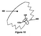
図10は、固定嚢切開432a内に埋め込まれた薬剤溶出デバイスの実施形態を示している。この例では、薬剤溶出デバイスは、嚢402上で中心嚢切開400の近くの固定嚢切開432a内に埋め込まれるプラグ500である。この例では、プラグ500は、プラグを固定嚢切開432a内に保持するように設計された機械的な特徴部を含む。
FIG. 10 illustrates an embodiment of a drug eluting device implanted within a fixed
図11に示す薬剤溶出プラグ500は、キャップ502を端部504で終了する本体506上に有する。孔隙510が、他の場合は薬剤溶出プラグ500に収容される薬剤の分散を可能にするために本体506上に含まれる。デバイス500の機械的特徴部の例示的な寸法は、以下の通りである。
The

図12は、固定嚢切開と共に使用される薬剤溶出デバイスの更に別の代替実施形態を示している。他の点では図11の実施形態と類似のものであるが、図12に示す実施形態は、固定嚢切開432内のデバイス500の改善した保持をもたらすための本体506に沿った腰部512の追加を含む。これに代えて、ボタン穴嚢切開は、デバイス500の強化された保持及び支持をもたらすために使用することができる。
FIG. 12 illustrates yet another alternative embodiment of a drug eluting device for use with a fixed capsulotomy. While otherwise similar to the embodiment of FIG. 11, the embodiment shown in FIG. 12 is the addition of a
図5A〜図6Bに示すデバイスと同様に、図13Aに示す代替実施形態は、固定嚢切開432内の改善した保持をもたらす末端キャップ514の追加を含む。図13Bは、中心嚢切開の近くではない嚢の領域内に配置される同じデバイスを示している。
Similar to the device shown in FIGS. 5A-6B, the alternative embodiment shown in FIG. 13A includes the addition of an
図14は、多くの実施形態によるレーザ支援型手術を眼に行う方法600を示している。本明細書に開示するあらゆる適切なシステムを含むあらゆる適切なシステムを方法600を実施するのに使用することができる。
FIG. 14 illustrates a
段階602では、水晶体嚢を切開するためにレーザを使用することによって固定嚢切開を眼の水晶体嚢内に形成する。固定嚢切開は、例えば、本明細書に開示されているように、あらゆる適切な手法を使用して眼内レンズ(IOL)の固定特徴部を収容するように構成される。多くの実施形態において、固定特徴部は、図6Bに示すなどの水晶体嚢切開の近くで水晶体嚢と接続するIOLの表面に対して横断方向に突出する。固定嚢切開は、例えば、ボタン穴、直線、骨形状、涙滴形状、円形、丸コーナを有する矩形、鋭いコーナを有する矩形、及び楕円形を含むあらゆる適切な形状を有することができる。あらゆる適切な数の固定嚢切開を水晶体嚢内に構成することができる。1つ又はそれよりも多くの固定嚢切開は、例えば、前嚢内、後嚢内、及び前嚢及び後嚢内などのあらゆる適切な位置に置くことができる。複数の固定嚢切開の各々は、IOLの対応する固定特徴部を収容するように構成することができる。複数の固定嚢切開が使用される時に、同じか又は異なる形状を使用することができる。多くの実施形態において、固定嚢切開及びIOLは、眼の乱視の矯正を行うためにIOLを眼に対して向けるように構成される。固定嚢切開は、例えば、回転対称のパターン、回転非対称のパターン、左右対称のパターン及び左右非対称のパターンを含む適切なパターンを形成するように配置することができる。パターンの非対称性は、パターンを嚢収縮の自然な非対称性の方向に対処するように向けることを可能にする。多くの実施形態において、固定嚢切開の少なくとも1つは、IOLが埋め込まれる時に、IOLの固定特徴部を通過する円に正接して細長い。更には、固定特徴部の少なくとも1つは、対応する固定嚢切開に隣接して水晶体嚢と嵌合するIOLの表面に対して横断方向に突出することができる。
In
段階604では、IOLの固定特徴部を固定嚢切開と結合する。IOLは、あらゆる適切な位置に配置することができる。例えば、IOLは、前眼房内、水晶体嚢上又は嚢内、後嚢の前側、及び前嚢の後側に置くことができる。IOLは、「ピギーバック」IOLとすることができる。第2のIOLは、IOL及び第2のIOLが両方とも水晶体嚢に結合されるように水晶体嚢に結合することができる。第2のIOLは、IOLに対して前方に位置決めすることができる。水晶体嚢に対する第2のIOLの向きは、レーザで水晶体嚢を通過して作成された1つよりも多い固定嚢切開を使用して拘束することができる。
In
上述の段階は実施形態による眼を治療する方法600を示すが、当業者は、本明細書に説明する教示に基づいて多くの変形を認識するであろう。段階は、異なる順番で完了することができる。段階は、追加又は削除することができる。段階の一部は、部分段階を含むことができる。段階の多くは、治療に有益である場合と同じ程度に頻繁に繰り返すことができる。
Although the above steps illustrate a
方法600の段階の1つ又はそれよりも多くは、本明細書に説明するような回路、例えば、プロセッサ、又はフィールドプログラマブルゲートアレイのプログラマブルアレイ論理部のような論理回路のうちの1つ又はそれよりも多くで実行することができる。回路は、方法600の段階の1つ又はそれよりも多くをもたらすようにプログラムすることができ、プログラムは、例えば、コンピュータ可読メモリ上に記憶されたプログラム命令、又はプログラマブルアレイ論理部又はフィールドプログラマブルゲートアレイのような論理回路のプログラムされた段階を含むことができる。
One or more of the steps of
図15は、多くの実施形態によるレーザ支援型手術を眼に行う方法610を示している。本明細書に開示するあらゆる適切なシステムを含むあらゆる適切なシステムを方法610を実施するのに使用することができる。
FIG. 15 illustrates a
段階612では、水晶体嚢を切開するためにレーザを使用することによって固定嚢切開を眼の水晶体嚢内に形成する。固定嚢切開は、例えば、本明細書に開示されているように、あらゆる適切な手法を使用して薬剤溶出部材を収容するように構成される。更には、薬剤溶出部材を収容するように構成された1つよりも多い固定嚢切開は、前嚢内、後嚢内、又は前後嚢の両方内を含むあらゆる適切な位置に形成及び/又は位置付けることができる。
In
段階614では、薬剤溶出部材を固定嚢切開に取外し可能に結合する。薬剤溶出部材の機械的特徴部は、水晶体嚢に対する薬剤溶出部材の位置を保持するために固定嚢切開を通して取外し可能に取り付けることができる。1つ又はそれよりも多くの追加の薬剤溶出部材を対応する追加の固定嚢切開と取外し可能に結合することができる。
In
上述の段階は実施形態による方法610を示すが、当業者は、本明細書に説明する教示に基づいて多くの変形を認識するであろう。段階は、異なる順番で完了することができる。段階は、追加又は削除することができる。段階の一部は、部分段階を含むことができる。段階の多くは、治療に有益である場合と同じ程度に頻繁に繰り返すことができる。
Although the above steps illustrate a
方法610の段階の1つ又はそれよりも多くは、本明細書に説明するような回路、例えば、プロセッサ、又はフィールドプログラマブルゲートアレイのプログラマブルアレイ論理部のような論理回路の1つ又はそれよりも多くで実行することができる。回路は、方法610の段階の1つ又はそれよりも多くをもたらすようにプログラムすることができ、プログラムは、例えば、コンピュータ可読メモリ上に記憶されたプログラム命令、又はプログラマブルアレイ論理部又はフィールドプログラマブルゲートアレイのような論理回路のプログラムされた段階を含むことができる。
One or more of the steps of
図16は、多くの実施形態による眼科的介入の方法650を示している。本明細書に開示するあらゆる適切なシステムを含むあらゆる適切なシステムを方法650を実施するのに使用することができる。 FIG. 16 illustrates a method 650 of ophthalmic intervention according to many embodiments. Any suitable system can be used to perform method 650, including any suitable system disclosed herein.
段階652では、固定嚢切開のパターンを眼の水晶体嚢内に作成する。固定嚢切開のパターンは、眼内レンズ(IOL)の固定特徴部に機械的に結合されるように構成される。パターンの各固定嚢切開は、例えば、本明細書に開示されているように、あらゆる適切な手法を使用して眼内レンズ(IOL)の対応する固定特徴部を収容するように構成される。多くの実施形態において、パターンの固定特徴部の少なくとも1つは、図6Bに示す対応する固定嚢切開に隣接して水晶体嚢と嵌合するIOLの表面に対して横断方向に突出する。パターンの固定嚢切開は、あらゆる適切な形状を有することができる。例えば、パターンの固定嚢切開の少なくとも1つは、ボタン穴形状、涙滴形状、丸形、鋭いコーナを有する矩形の形状、丸コーナを有する矩形の形状、直線形状、骨形状、及び楕円形の形状を有することができる。多くの実施形態において、固定嚢切開のパターンを作成する段階は、水晶体嚢をレーザで切開する段階を含む。
In
段階654では、1次嚢切開を水晶体嚢内に作成する。1次嚢切開は、前嚢切開、後嚢切開、及び/又は前嚢切開及び後嚢切開の両方とすることができる。1次嚢切開は、あらゆる適切な境界形状を有するように作成することができる。例えば、1次嚢切開の境界形状は、円形、楕円形、多角形、円弧状、及び直線とすることができる。多くの実施形態において、1次嚢切開を作成する段階は、水晶体嚢をレーザで切開する段階を含む。
In
固定嚢切開は、1次嚢切開の周りのあらゆる適切な位置に配置することができる。例えば、固定嚢切開のパターンの作成は、1次嚢切開の境界の周りに実質的に同等に離間した位置で固定嚢切開の2つ又はそれよりも多くを置く段階を含むことができる。固定嚢切開のパターンの作成は、1次嚢切開の境界の周りに不均一に離間した位置で2つ又はそれよりも多くの固定嚢切開を置く段階を含むことができる。固定嚢切開のパターンは、回転対称、回転非対称、左右対称、又は左右非対称であるように作成することができる。 The fixed capsulotomy can be placed at any suitable location around the primary capsulotomy. For example, creating a fixed capsulotomy pattern can include placing two or more of the fixed capsulotomy at substantially equally spaced locations around the boundary of the primary capsulotomy. Creating a fixed capsulotomy pattern can include placing two or more fixed capsulotomy at non-uniformly spaced locations around the boundary of the primary capsulotomy. The pattern of fixed capsulotomy can be created to be rotationally symmetric, rotationally asymmetrical, bilaterally symmetric, or bilaterally asymmetric.
段階656では、水晶体嚢とIOLとの間に確立される転回の向きを決定する。例えば、転回の向きの決定は、眼の非点収差軸を決定して眼の非点収差軸に少なくとも部分的に基づいて転回の向きを決定する段階を含むことができる。パターンの固定嚢切開は、IOLが水晶体嚢と組み付けられる時に決定された転回の向きを達成するように構成された位置に配置することができる。転回の向きは、水晶体嚢の収縮の自然な非対称性の方向に対応するように決定することができる。
In
段階658では、水晶体嚢にIOLを結合する前に、IOLが水晶体嚢に対して決定された転回の向きにあるという確認が達成される。転回の向きの確認は、あらゆる適切な方法を使用して達成することができる。例えば、転回の向きの確認は、IOLの鍵結合した特徴部の転回の向きを観測する段階を含むことができる。転回の向きは、水晶体嚢の鍵結合した特徴部の転回の向きを観測する段階を含むことができる。IOLの鍵結合した特徴部は、固定特徴部の相対的な位置決めとすることができる。例えば、多くの実施形態において、パターンは、結果として2つの左右対称のパターン半分になるために二等分角に沿って二等分することができ、二等分角は、鍵結合した特徴部として使用することができる。IOL上の鍵結合した特徴部はまた、IOL内に作成される1つ又はそれよりも多くの鍵結合マーカとすることができる。水晶体嚢の鍵結合した特徴部は、水晶体嚢の1つ又はそれよりも多くの解剖学的目印を含むことができる。水晶体嚢の鍵結合した特徴部は、水晶体嚢内に作成される1つ又はそれよりも多くのマーカを含むことができる。
In
段階660では、IOLの固定特徴部を水晶体嚢において固定嚢切開のパターンと機械的に係合させることによってIOLを水晶体嚢に結合する。IOLは、水晶体嚢に結合された時に、例えば、前眼房内、眼の水晶体嚢内、眼の後嚢の前側上、又は眼の前嚢の後側上に位置付けることができる。
In
上述の段階は実施形態による方法650を示すが、当業者は、本明細書に説明する教示に基づいて多くの変形を認識するであろう。段階は、異なる順番で完了することができる。段階は、追加又は削除することができる。段階の一部は、部分段階を含むことができる。段階の多くは、治療に有益である場合と同じ程度に頻繁に繰り返すことができる。 Although the above steps illustrate a method 650 according to embodiments, those skilled in the art will recognize many variations based on the teachings described herein. The stages can be completed in a different order. Stages can be added or deleted. Some of the stages can include partial stages. Many of the stages can be repeated as often as they are beneficial for treatment.
方法650の段階の1つ又はそれよりも多くは、本明細書に説明するような回路、例えば、プロセッサ、又はフィールドプログラマブルゲートアレイのプログラマブルアレイ論理部のような論理回路の1つ又はそれよりも多くで実行することができる。回路は、方法650の段階の1つ又はそれよりも多くをもたらすようにプログラムすることができ、プログラムは、例えば、コンピュータ可読メモリ上に記憶されたプログラム命令、又はプログラマブルアレイ論理部又はフィールドプログラマブルゲートアレイのような論理回路のプログラムされた段階を含むことができる。 One or more of the steps of method 650 may be more than one or more of the circuits as described herein, eg, a logic circuit such as a processor, or a programmable array logic portion of a field programmable gate array. Can be done with many. The circuit can be programmed to provide one or more of the steps of method 650, which can be programmed, for example, program instructions stored on a computer readable memory, or a programmable array logic or field programmable gate. It can include programmed stages of logic circuits such as arrays.
方法600、610、及び650は、多くの方法のうちの1つ又はそれよりも多くで組み合わせることができ、例えば、各方法の1つ又はそれよりも多くの段階は、組み合わせることができ、段階は、異なる順番で完了するか、追加又は削除することができ、組み合わされた段階の一部は、部分段階を含むことができ、かつ本明細書に説明するように回路で実行することができる。
本発明の好ましい実施形態を図示して説明したが、そのような実施形態は、一例としてのみ示したことは当業者には明らかであろう。多くの変形、変更、及び置換は、ここで本発明から逸脱することなく当業者に想起されると考えられる。本明細書に説明する本発明の実施形態に対して様々な代替を本発明を実施する際に使用することができることを理解しなければならない。特許請求の範囲は、本発明の範囲を定め、これらの特許請求の範囲及びそれらの均等物の範囲内の方法及び構造は、本発明の範囲によって包含されるように意図されている。 While preferred embodiments of the invention have been illustrated and described, it will be apparent to those skilled in the art that such embodiments have been presented by way of example only. Many variations, modifications, and substitutions will now occur to those skilled in the art without departing from the invention. It should be understood that various alternatives to the embodiments of the invention described herein can be used in practicing the invention. The following claims define the scope of the invention, and methods and structures within the scope of these claims and their equivalents are intended to be encompassed by the scope of the present invention.
402 水晶体嚢
432 マイクロフェムト切開
440 眼内レンズ
444 眼球レンズ
402
Claims (12)
複数のレーザパルスを含む治療ビームを生成するように構成されたレーザ源と、
治療レーザ送出アセンブリに作動的に結合された撮像アセンブリをそれらが少なくとも1つの共通光学要素を共有するように含み、1つ又はそれよりも多くのターゲット組織構造体に関する画像情報を取得し、かつ該ターゲット組織構造体のうちの少なくとも1つに破壊を引き起こすために3次元パターンで前記治療ビームを向けるように構成された一体型光学系と、
前記レーザ源と前記一体型光学系とに作動的に結合され、複数の固定嚢切開を前記水晶体嚢に切り込むように該系を制御するように構成されたコントローラであって、該固定嚢切開が、眼内レンズ(IOL)の固定特徴部を収容するように構成される、前記コントローラと、
を含み、
各々の前記複数の固定嚢切開の横断方向の各位置は、前記コントローラによる前記水晶体嚢の非対称性と関連しない少なくとも一つの眼の非対称性の決定に少なくとも部分的に基づき、
前記固定嚢切開は、当該固定嚢切開が、嚢収縮の自然な非対称性の方向に対応するように配向された回転非対称のパターンを形成するように配置され、
前記眼の内部での前記IOLの整列を保証するために、前記IOLの非対称軸を画定する、対応する一つの前記固定特徴部を受容するように、前記固定嚢切開の一つは、それを通る眼の非対称軸を区別するように他の固定嚢切開とは異なる形状を有する、ことを特徴とするシステム。 A system for performing laser-assisted surgery on an eye having a capsular bag,
A laser source configured to generate a treatment beam including a plurality of laser pulses;
Including imaging assemblies operatively coupled to the treatment laser delivery assembly such that they share at least one common optical element to obtain image information about one or more target tissue structures; and An integrated optical system configured to direct the treatment beam in a three-dimensional pattern to cause destruction to at least one of the target tissue structures;
A controller operatively coupled to the laser source and the integrated optical system and configured to control the system to cut a plurality of fixed capsule incisions into the lens capsule; , configured to accommodate pinning feature of intraocular lenses (IOL), and said controller,
Including
Each transverse position of each of the plurality of fixed capsulotomy is based at least in part on a determination of at least one eye asymmetry that is not associated with asymmetry of the capsular bag by the controller;
The fixed capsulotomy is arranged such that the fixed capsulotomy forms a rotationally asymmetric pattern oriented to correspond to the natural asymmetry direction of capsular contraction;
To ensure alignment of the IOL inside the eye, to define an asymmetric axis of the IOL, to receive the pinning feature of a corresponding one, the one one fixed capsulorhexis is it A system characterized by having a shape different from other fixed capsulotomy so as to distinguish the asymmetric axis of the passing eye.
前記IOL上の対応する特徴部が、第1の部分と第2の部分を含み、該第1の部分は、前記固定嚢切開を通過するサイズを有する第1の断面寸法を有し、該第2の部分は、該第1の断面寸法よりも小さい第2の断面寸法を有し、
前記特徴部は、前記第1の部分が、前記第2の部分が前記嚢を通って延びる時に該嚢の第1の側面上に保持されるように、前記IOLの本体からある距離を延びる、
ことを特徴とする請求項1に記載のシステム。 The plurality of fixed capsule incisions are formed in the lens capsule by using the laser to cut through the lens capsule, and each fixed capsule incision is configured to accommodate a corresponding fixed feature of the IOL. And
Corresponding features on the IOL include a first portion and a second portion, the first portion having a first cross-sectional dimension that is sized to pass through the fixed capsulotomy, The second portion has a second cross-sectional dimension that is smaller than the first cross-sectional dimension;
The feature extends a distance from the body of the IOL so that the first portion is retained on a first side of the sac when the second portion extends through the sac.
The system according to claim 1.
ことを特徴とする請求項3に記載のシステム。 Fixed capsulotomy with different shapes include buttonholes, straight lines, teardrop shapes, rounds, rectangles with round corners, rectangles with sharp corners, squares with round corners, squares with sharp corners, straight lines, and ellipses Having a shape selected from the group consisting of shapes,
The system according to claim 3.
前記IOLは、該IOLの収差矯正軸に対する前記特徴部の位置の予め決められた構成を含み、
前記固定嚢切開は、前記眼の収差矯正を提供するために前記IOLの前記収差矯正軸を該眼の収差軸と位置合わせする位置に置かれ、
前記固定嚢切開の位置が、前記IOLを前記眼の前記軸と位置合わせさせるために該眼の前記収差矯正軸に関連して回転される、
ことを特徴とする請求項3に記載のシステム。 The plurality of fixed capsulotomy and the IOL are configured to orient the IOL relative to the eye to provide correction of astigmatism of the eye;
The IOL includes a predetermined configuration of the position of the feature relative to the aberration correction axis of the IOL;
The fixed capsulotomy is positioned to align the aberration correction axis of the IOL with the aberration axis of the eye to provide aberration correction of the eye;
The position of the fixed capsulotomy is rotated relative to the aberration correction axis of the eye to align the IOL with the axis of the eye;
The system according to claim 3.
前記固定特徴部の少なくとも1つが、対応する前記固定嚢切開に隣接して前記水晶体嚢と接続するように構成された前記IOLの表面に対して横断方向に突出する、
ことを特徴とする請求項3に記載のシステム。 At least one of the fixation capsulotomy is extended tangential to a circle passing through the fixation feature of the IOL when the IOL is implanted;
At least one of the fixation features protrudes transversely to the surface of the IOL configured to connect with the capsular bag adjacent to the corresponding fixation capsule incision;
The system according to claim 3.
前記水晶体嚢は、前嚢と後嚢を含み、
前記IOLは、前記前眼房内、前記水晶体嚢上又は内、前記後嚢の前側上、及び前記前嚢の後側上から構成される群から選択された位置に置かれるように構成される、
ことを特徴とする請求項2に記載のシステム。 The eye has an anterior chamber;
The lens capsule includes an anterior capsule and a posterior capsule;
The IOL is configured to be placed in a position selected from the group consisting of in the anterior chamber, on or in the lens capsule, on the anterior side of the posterior capsule, and on the posterior side of the anterior capsule ,
The system according to claim 2.
前記第2のIOLは、前記IOLに対して前方に位置決めされ、
前記水晶体嚢に対する前記第2のIOLの向きが、システムによって該水晶体嚢を通して作成された2つ又はそれよりも多くの固定嚢切開を使用して拘束される、
ことを特徴とする請求項3に記載のシステム。 The fixed capsulotomy is configured to couple a second IOL to the lens capsule such that the IOL and the second IOL are both coupled to the lens capsule;
The second IOL is positioned forward relative to the IOL;
The orientation of the second IOL relative to the capsular bag is constrained using two or more fixed capsulotomy created by the system through the capsular bag;
The system according to claim 3.
前記固定嚢切開は、前記前嚢、前記後嚢、及び該前嚢及び後嚢の両方から構成される群から選択された位置に置かれる、
ことを特徴とする請求項2に記載のシステム。 The lens capsule includes an anterior capsule and a posterior capsule;
The fixed capsulotomy is placed at a location selected from the group consisting of the anterior capsule, the posterior capsule, and both the anterior and posterior capsules;
The system according to claim 2.
を含むことを特徴とする請求項1に記載のシステム。 The controller is configured to control the system to cut the fixed sac incision into the capsular bag, the fixed sac incision configured to receive a drug eluting member, and the mechanical of the drug eluting member A controller configured to be removably mounted through a portion of the fixed capsule incision to maintain a position of the drug eluting member relative to the lens capsule;
The system of claim 1, comprising:
Applications Claiming Priority (3)
| Application Number | Priority Date | Filing Date | Title |
|---|---|---|---|
| US201361788201P | 2013-03-15 | 2013-03-15 | |
| US61/788,201 | 2013-03-15 | ||
| PCT/US2014/021119 WO2014149832A1 (en) | 2013-03-15 | 2014-03-06 | Microfemtotomy methods and systems |
Publications (3)
| Publication Number | Publication Date |
|---|---|
| JP2016511072A JP2016511072A (en) | 2016-04-14 |
| JP2016511072A5 JP2016511072A5 (en) | 2018-11-15 |
| JP6444973B2 true JP6444973B2 (en) | 2018-12-26 |
Family
ID=50382686
Family Applications (1)
| Application Number | Title | Priority Date | Filing Date |
|---|---|---|---|
| JP2016500726A Expired - Fee Related JP6444973B2 (en) | 2013-03-15 | 2014-03-06 | Microfemto incision method and system |
Country Status (6)
| Country | Link |
|---|---|
| US (5) | US20140276681A1 (en) |
| EP (2) | EP2968003B1 (en) |
| JP (1) | JP6444973B2 (en) |
| AU (2) | AU2014237804B2 (en) |
| CA (2) | CA2907114C (en) |
| WO (1) | WO2014149832A1 (en) |
Families Citing this family (8)
| Publication number | Priority date | Publication date | Assignee | Title |
|---|---|---|---|---|
| US20130218145A1 (en) | 2010-05-10 | 2013-08-22 | Tel Hashomer Medical Research Infrastructure And Services Ltd. | System and method for treating an eye |
| US11771596B2 (en) | 2010-05-10 | 2023-10-03 | Ramot At Tel-Aviv University Ltd. | System and method for treating an eye |
| AU2014237804B2 (en) * | 2013-03-15 | 2018-03-22 | Amo Development, Llc | Microfemtotomy methods and systems |
| US10369053B2 (en) | 2013-04-17 | 2019-08-06 | Optimedica Corporation | Corneal topography measurements and fiducial mark incisions in laser surgical procedures |
| AU2015320309B2 (en) | 2014-09-25 | 2020-07-23 | Amo Development, Llc | Methods and systems for corneal topography, blink detection and laser eye surgery |
| WO2018049414A1 (en) * | 2016-09-12 | 2018-03-15 | Lensar, Inc. | Laser methods and systems for the aligned insertion of devices into a structure of the eye |
| IL279749B2 (en) | 2018-07-02 | 2024-04-01 | Belkin Vision Ltd | Direct selective laser trabeculoplasty |
| US20230201034A1 (en) * | 2020-07-19 | 2023-06-29 | Belkin Vision Ltd. | Automated capsulotomy |
Family Cites Families (39)
| Publication number | Priority date | Publication date | Assignee | Title |
|---|---|---|---|---|
| US5722970A (en) * | 1991-04-04 | 1998-03-03 | Premier Laser Systems, Inc. | Laser surgical method using transparent probe |
| US6111645A (en) | 1991-04-29 | 2000-08-29 | Massachusetts Institute Of Technology | Grating based phase control optical delay line |
| WO1992019930A1 (en) | 1991-04-29 | 1992-11-12 | Massachusetts Institute Of Technology | Method and apparatus for optical imaging and measurement |
| US5984916A (en) | 1993-04-20 | 1999-11-16 | Lai; Shui T. | Ophthalmic surgical laser and method |
| JP3261244B2 (en) | 1993-12-17 | 2002-02-25 | ブラザー工業株式会社 | Scanning optical device |
| US5743902A (en) | 1995-01-23 | 1998-04-28 | Coherent, Inc. | Hand-held laser scanner |
| US6454761B1 (en) | 1995-01-30 | 2002-09-24 | Philip D. Freedman | Laser surgery device and method |
| JPH0955843A (en) | 1995-08-10 | 1997-02-25 | Nec Corp | Picture data transmission/reception system |
| US5720894A (en) | 1996-01-11 | 1998-02-24 | The Regents Of The University Of California | Ultrashort pulse high repetition rate laser system for biological tissue processing |
| US7655002B2 (en) | 1996-03-21 | 2010-02-02 | Second Sight Laser Technologies, Inc. | Lenticular refractive surgery of presbyopia, other refractive errors, and cataract retardation |
| US6019472A (en) | 1997-05-12 | 2000-02-01 | Koester; Charles J. | Contact lens element for examination or treatment of ocular tissues |
| US6053613A (en) | 1998-05-15 | 2000-04-25 | Carl Zeiss, Inc. | Optical coherence tomography with new interferometer |
| US6478821B1 (en) * | 2000-01-12 | 2002-11-12 | Advanced Medical Optics, Inc. | Iris fixated intraocular lens and method of implantation |
| CA2420038C (en) * | 2000-08-30 | 2010-11-09 | John Hopkins University | Devices for intraocular drug delivery |
| AUPR173100A0 (en) * | 2000-11-28 | 2000-12-21 | Maloof, Anthony | A device for sealing the capsular bag of an eye and a method for delivering fluid or treatment substances to the lens of an eye |
| JP2002360616A (en) * | 2001-06-08 | 2002-12-17 | Canon Inc | Intraocular inserting lens |
| US7001426B2 (en) | 2002-11-18 | 2006-02-21 | The Institute For Eye Research | One-piece minicapsulorhexis valve |
| US8394084B2 (en) | 2005-01-10 | 2013-03-12 | Optimedica Corporation | Apparatus for patterned plasma-mediated laser trephination of the lens capsule and three dimensional phaco-segmentation |
| WO2007082342A1 (en) * | 2006-01-17 | 2007-07-26 | Minas Theodore Coroneo | A capsular implant for maintaining the shape and/or position of an opening formed by capsulorhexis |
| US8262646B2 (en) | 2006-01-20 | 2012-09-11 | Lensar, Inc. | System and method for providing the shaped structural weakening of the human lens with a laser |
| JP2007284420A (en) | 2006-03-20 | 2007-11-01 | Toshiharu Fukai | Water having anticancer property and method for producing the same water |
| US20080103592A1 (en) * | 2006-10-30 | 2008-05-01 | Calhoun Vision, Inc. | Piggyback lenses |
| US20110319875A1 (en) | 2007-01-19 | 2011-12-29 | Frieder Loesel | Apparatus and Method for Morphing a Three-Dimensional Target Surface into a Two-Dimensional Image for Use in Guiding a Laser Beam in Ocular Surgery |
| EP2120789B1 (en) * | 2007-03-05 | 2010-10-06 | Nulens Ltd | Unitary accommodating intraocular lenses (aiols) and discrete base members for use therewith |
| US20090012507A1 (en) * | 2007-03-13 | 2009-01-08 | William Culbertson | Method for patterned plasma-mediated modification of the crystalline lens |
| DE102007028042B3 (en) | 2007-06-14 | 2008-08-07 | Universität Zu Lübeck | Using laser to make bubbles or cavities in transparent materials by focused, non-linear pulse absorption, operates at specified wavelength and pulse duration with controlled, uniform intensity |
| US7717907B2 (en) | 2007-12-17 | 2010-05-18 | Technolas Perfect Vision Gmbh | Method for intrastromal refractive surgery |
| US8480659B2 (en) * | 2008-07-25 | 2013-07-09 | Lensar, Inc. | Method and system for removal and replacement of lens material from the lens of an eye |
| CA2979355C (en) * | 2009-05-18 | 2023-02-21 | Dose Medical Corporation | Drug eluting ocular implant |
| US8382745B2 (en) | 2009-07-24 | 2013-02-26 | Lensar, Inc. | Laser system and method for astigmatic corrections in association with cataract treatment |
| US9833358B2 (en) | 2010-01-08 | 2017-12-05 | Optimedica Corporation | Method and system for modifying eye tissue and intraocular lenses |
| US8845625B2 (en) * | 2010-01-22 | 2014-09-30 | Optimedica Corporation | Method and apparatus for automated placement of scanned laser capsulorhexis incisions |
| US8414564B2 (en) | 2010-02-18 | 2013-04-09 | Alcon Lensx, Inc. | Optical coherence tomographic system for ophthalmic surgery |
| US8652206B2 (en) * | 2010-04-12 | 2014-02-18 | Samuel Masket | Anti-dysphotopic intraocular lens and method |
| US8845624B2 (en) | 2010-06-25 | 2014-09-30 | Alcon LexSx, Inc. | Adaptive patient interface |
| EP2422747B1 (en) * | 2010-08-26 | 2019-04-10 | Stevens, Julian Douglas | Intraocular implant |
| EP3170474B1 (en) * | 2010-08-26 | 2019-05-01 | Stevens, Julian Douglas | Intraocular implant |
| US9681981B2 (en) * | 2012-06-08 | 2017-06-20 | Julian Douglas STEVENS | Intraocular implant and method for fixing same into an eye |
| AU2014237804B2 (en) * | 2013-03-15 | 2018-03-22 | Amo Development, Llc | Microfemtotomy methods and systems |
-
2014
- 2014-03-06 AU AU2014237804A patent/AU2014237804B2/en not_active Ceased
- 2014-03-06 WO PCT/US2014/021119 patent/WO2014149832A1/en active Application Filing
- 2014-03-06 CA CA2907114A patent/CA2907114C/en active Active
- 2014-03-06 EP EP14712946.4A patent/EP2968003B1/en active Active
- 2014-03-06 JP JP2016500726A patent/JP6444973B2/en not_active Expired - Fee Related
- 2014-03-06 CA CA3144057A patent/CA3144057A1/en not_active Abandoned
- 2014-03-06 EP EP22184216.4A patent/EP4112019A1/en active Pending
- 2014-03-06 US US14/199,087 patent/US20140276681A1/en not_active Abandoned
-
2018
- 2018-03-23 AU AU2018202098A patent/AU2018202098B2/en not_active Ceased
- 2018-04-12 US US15/952,147 patent/US10888459B2/en active Active
-
2020
- 2020-12-08 US US17/115,738 patent/US20210085523A1/en not_active Abandoned
-
2021
- 2021-01-08 US US17/145,257 patent/US11554043B2/en active Active
-
2023
- 2023-01-15 US US18/154,838 patent/US20230190526A1/en active Pending
Also Published As
| Publication number | Publication date |
|---|---|
| US20180296392A1 (en) | 2018-10-18 |
| CA3144057A1 (en) | 2014-09-25 |
| US20210085523A1 (en) | 2021-03-25 |
| AU2014237804A1 (en) | 2015-10-08 |
| EP2968003A1 (en) | 2016-01-20 |
| CA2907114C (en) | 2021-07-13 |
| AU2018202098A1 (en) | 2018-04-19 |
| US10888459B2 (en) | 2021-01-12 |
| EP2968003B1 (en) | 2022-07-13 |
| JP2016511072A (en) | 2016-04-14 |
| US20210128354A1 (en) | 2021-05-06 |
| US20230190526A1 (en) | 2023-06-22 |
| AU2018202098B2 (en) | 2019-11-21 |
| AU2014237804B2 (en) | 2018-03-22 |
| CA2907114A1 (en) | 2014-09-25 |
| US11554043B2 (en) | 2023-01-17 |
| WO2014149832A1 (en) | 2014-09-25 |
| EP4112019A1 (en) | 2023-01-04 |
| US20140276681A1 (en) | 2014-09-18 |
Similar Documents
| Publication | Publication Date | Title |
|---|---|---|
| JP6495428B2 (en) | Intraocular lens | |
| US11554043B2 (en) | Microfemtotomy methods and systems | |
| AU2016202527B2 (en) | Apparatus for creating incisions to improve intraocular lens placement | |
| AU2012241152B2 (en) | Apparatus for creating incisions to improve intraocular lens placement |
Legal Events
| Date | Code | Title | Description |
|---|---|---|---|
| A621 | Written request for application examination |
Free format text: JAPANESE INTERMEDIATE CODE: A621 Effective date: 20170104 |
|
| RD04 | Notification of resignation of power of attorney |
Free format text: JAPANESE INTERMEDIATE CODE: A7424 Effective date: 20170420 |
|
| A977 | Report on retrieval |
Free format text: JAPANESE INTERMEDIATE CODE: A971007 Effective date: 20171106 |
|
| A131 | Notification of reasons for refusal |
Free format text: JAPANESE INTERMEDIATE CODE: A131 Effective date: 20171113 |
|
| A521 | Request for written amendment filed |
Free format text: JAPANESE INTERMEDIATE CODE: A523 Effective date: 20180123 |
|
| A521 | Request for written amendment filed |
Free format text: JAPANESE INTERMEDIATE CODE: A821 Effective date: 20180330 |
|
| RD02 | Notification of acceptance of power of attorney |
Free format text: JAPANESE INTERMEDIATE CODE: A7422 Effective date: 20180330 |
|
| RD04 | Notification of resignation of power of attorney |
Free format text: JAPANESE INTERMEDIATE CODE: A7424 Effective date: 20180405 |
|
| A131 | Notification of reasons for refusal |
Free format text: JAPANESE INTERMEDIATE CODE: A131 Effective date: 20180703 |
|
| A521 | Request for written amendment filed |
Free format text: JAPANESE INTERMEDIATE CODE: A523 Effective date: 20181003 |
|
| A524 | Written submission of copy of amendment under article 19 pct |
Free format text: JAPANESE INTERMEDIATE CODE: A524 Effective date: 20181003 |
|
| TRDD | Decision of grant or rejection written | ||
| A01 | Written decision to grant a patent or to grant a registration (utility model) |
Free format text: JAPANESE INTERMEDIATE CODE: A01 Effective date: 20181030 |
|
| A61 | First payment of annual fees (during grant procedure) |
Free format text: JAPANESE INTERMEDIATE CODE: A61 Effective date: 20181128 |
|
| R150 | Certificate of patent or registration of utility model |
Ref document number: 6444973 Country of ref document: JP Free format text: JAPANESE INTERMEDIATE CODE: R150 |
|
| R250 | Receipt of annual fees |
Free format text: JAPANESE INTERMEDIATE CODE: R250 |
|
| R250 | Receipt of annual fees |
Free format text: JAPANESE INTERMEDIATE CODE: R250 |
|
| LAPS | Cancellation because of no payment of annual fees |