JP6442942B2 - Driver status determination device - Google Patents
Driver status determination device Download PDFInfo
- Publication number
- JP6442942B2 JP6442942B2 JP2014184906A JP2014184906A JP6442942B2 JP 6442942 B2 JP6442942 B2 JP 6442942B2 JP 2014184906 A JP2014184906 A JP 2014184906A JP 2014184906 A JP2014184906 A JP 2014184906A JP 6442942 B2 JP6442942 B2 JP 6442942B2
- Authority
- JP
- Japan
- Prior art keywords
- driver
- state
- far
- infrared image
- detected
- Prior art date
- Legal status (The legal status is an assumption and is not a legal conclusion. Google has not performed a legal analysis and makes no representation as to the accuracy of the status listed.)
- Active
Links
- 210000001508 eye Anatomy 0.000 claims description 68
- 238000001514 detection method Methods 0.000 claims description 57
- 230000002159 abnormal effect Effects 0.000 claims description 50
- 230000029058 respiratory gaseous exchange Effects 0.000 claims description 46
- 230000000241 respiratory effect Effects 0.000 claims description 45
- 210000003928 nasal cavity Anatomy 0.000 claims description 33
- 210000001331 nose Anatomy 0.000 claims description 29
- 238000000034 method Methods 0.000 claims description 21
- 239000011521 glass Substances 0.000 claims description 12
- 230000004397 blinking Effects 0.000 claims description 10
- 239000000284 extract Substances 0.000 claims description 6
- 238000000605 extraction Methods 0.000 claims description 6
- 230000001815 facial effect Effects 0.000 description 20
- 230000005856 abnormality Effects 0.000 description 7
- 238000010586 diagram Methods 0.000 description 5
- 210000000214 mouth Anatomy 0.000 description 5
- 210000005252 bulbus oculi Anatomy 0.000 description 4
- 210000000744 eyelid Anatomy 0.000 description 4
- 206010041349 Somnolence Diseases 0.000 description 2
- 230000007423 decrease Effects 0.000 description 2
- 230000035945 sensitivity Effects 0.000 description 2
- 125000002066 L-histidyl group Chemical group [H]N1C([H])=NC(C([H])([H])[C@](C(=O)[*])([H])N([H])[H])=C1[H] 0.000 description 1
- 208000032140 Sleepiness Diseases 0.000 description 1
- 230000000694 effects Effects 0.000 description 1
- 230000004399 eye closure Effects 0.000 description 1
- 230000006870 function Effects 0.000 description 1
- 238000005286 illumination Methods 0.000 description 1
- 238000003384 imaging method Methods 0.000 description 1
- 238000012544 monitoring process Methods 0.000 description 1
- 230000010352 nasal breathing Effects 0.000 description 1
- 230000005855 radiation Effects 0.000 description 1
- 230000037321 sleepiness Effects 0.000 description 1
- 239000000126 substance Substances 0.000 description 1
Images


Classifications
-
- A—HUMAN NECESSITIES
- A61—MEDICAL OR VETERINARY SCIENCE; HYGIENE
- A61B—DIAGNOSIS; SURGERY; IDENTIFICATION
- A61B5/00—Measuring for diagnostic purposes; Identification of persons
- A61B5/16—Devices for psychotechnics; Testing reaction times ; Devices for evaluating the psychological state
- A61B5/18—Devices for psychotechnics; Testing reaction times ; Devices for evaluating the psychological state for vehicle drivers or machine operators
-
- A—HUMAN NECESSITIES
- A61—MEDICAL OR VETERINARY SCIENCE; HYGIENE
- A61B—DIAGNOSIS; SURGERY; IDENTIFICATION
- A61B5/00—Measuring for diagnostic purposes; Identification of persons
- A61B5/0059—Measuring for diagnostic purposes; Identification of persons using light, e.g. diagnosis by transillumination, diascopy, fluorescence
- A61B5/0075—Measuring for diagnostic purposes; Identification of persons using light, e.g. diagnosis by transillumination, diascopy, fluorescence by spectroscopy, i.e. measuring spectra, e.g. Raman spectroscopy, infrared absorption spectroscopy
-
- A—HUMAN NECESSITIES
- A61—MEDICAL OR VETERINARY SCIENCE; HYGIENE
- A61B—DIAGNOSIS; SURGERY; IDENTIFICATION
- A61B5/00—Measuring for diagnostic purposes; Identification of persons
- A61B5/0059—Measuring for diagnostic purposes; Identification of persons using light, e.g. diagnosis by transillumination, diascopy, fluorescence
- A61B5/0077—Devices for viewing the surface of the body, e.g. camera, magnifying lens
-
- A—HUMAN NECESSITIES
- A61—MEDICAL OR VETERINARY SCIENCE; HYGIENE
- A61B—DIAGNOSIS; SURGERY; IDENTIFICATION
- A61B5/00—Measuring for diagnostic purposes; Identification of persons
- A61B5/01—Measuring temperature of body parts ; Diagnostic temperature sensing, e.g. for malignant or inflamed tissue
- A61B5/015—By temperature mapping of body part
-
- A—HUMAN NECESSITIES
- A61—MEDICAL OR VETERINARY SCIENCE; HYGIENE
- A61B—DIAGNOSIS; SURGERY; IDENTIFICATION
- A61B5/00—Measuring for diagnostic purposes; Identification of persons
- A61B5/08—Detecting, measuring or recording devices for evaluating the respiratory organs
-
- A—HUMAN NECESSITIES
- A61—MEDICAL OR VETERINARY SCIENCE; HYGIENE
- A61B—DIAGNOSIS; SURGERY; IDENTIFICATION
- A61B5/00—Measuring for diagnostic purposes; Identification of persons
- A61B5/08—Detecting, measuring or recording devices for evaluating the respiratory organs
- A61B5/0816—Measuring devices for examining respiratory frequency
-
- A—HUMAN NECESSITIES
- A61—MEDICAL OR VETERINARY SCIENCE; HYGIENE
- A61B—DIAGNOSIS; SURGERY; IDENTIFICATION
- A61B5/00—Measuring for diagnostic purposes; Identification of persons
- A61B5/68—Arrangements of detecting, measuring or recording means, e.g. sensors, in relation to patient
- A61B5/6887—Arrangements of detecting, measuring or recording means, e.g. sensors, in relation to patient mounted on external non-worn devices, e.g. non-medical devices
- A61B5/6893—Cars
-
- A—HUMAN NECESSITIES
- A61—MEDICAL OR VETERINARY SCIENCE; HYGIENE
- A61B—DIAGNOSIS; SURGERY; IDENTIFICATION
- A61B5/00—Measuring for diagnostic purposes; Identification of persons
- A61B5/72—Signal processing specially adapted for physiological signals or for diagnostic purposes
- A61B5/7271—Specific aspects of physiological measurement analysis
- A61B5/7278—Artificial waveform generation or derivation, e.g. synthesising signals from measured signals
-
- A—HUMAN NECESSITIES
- A61—MEDICAL OR VETERINARY SCIENCE; HYGIENE
- A61B—DIAGNOSIS; SURGERY; IDENTIFICATION
- A61B5/00—Measuring for diagnostic purposes; Identification of persons
- A61B5/72—Signal processing specially adapted for physiological signals or for diagnostic purposes
- A61B5/7271—Specific aspects of physiological measurement analysis
- A61B5/7282—Event detection, e.g. detecting unique waveforms indicative of a medical condition
-
- B—PERFORMING OPERATIONS; TRANSPORTING
- B60—VEHICLES IN GENERAL
- B60K—ARRANGEMENT OR MOUNTING OF PROPULSION UNITS OR OF TRANSMISSIONS IN VEHICLES; ARRANGEMENT OR MOUNTING OF PLURAL DIVERSE PRIME-MOVERS IN VEHICLES; AUXILIARY DRIVES FOR VEHICLES; INSTRUMENTATION OR DASHBOARDS FOR VEHICLES; ARRANGEMENTS IN CONNECTION WITH COOLING, AIR INTAKE, GAS EXHAUST OR FUEL SUPPLY OF PROPULSION UNITS IN VEHICLES
- B60K28/00—Safety devices for propulsion-unit control, specially adapted for, or arranged in, vehicles, e.g. preventing fuel supply or ignition in the event of potentially dangerous conditions
- B60K28/02—Safety devices for propulsion-unit control, specially adapted for, or arranged in, vehicles, e.g. preventing fuel supply or ignition in the event of potentially dangerous conditions responsive to conditions relating to the driver
- B60K28/06—Safety devices for propulsion-unit control, specially adapted for, or arranged in, vehicles, e.g. preventing fuel supply or ignition in the event of potentially dangerous conditions responsive to conditions relating to the driver responsive to incapacity of driver
- B60K28/066—Safety devices for propulsion-unit control, specially adapted for, or arranged in, vehicles, e.g. preventing fuel supply or ignition in the event of potentially dangerous conditions responsive to conditions relating to the driver responsive to incapacity of driver actuating a signalling device
-
- B—PERFORMING OPERATIONS; TRANSPORTING
- B60—VEHICLES IN GENERAL
- B60W—CONJOINT CONTROL OF VEHICLE SUB-UNITS OF DIFFERENT TYPE OR DIFFERENT FUNCTION; CONTROL SYSTEMS SPECIALLY ADAPTED FOR HYBRID VEHICLES; ROAD VEHICLE DRIVE CONTROL SYSTEMS FOR PURPOSES NOT RELATED TO THE CONTROL OF A PARTICULAR SUB-UNIT
- B60W10/00—Conjoint control of vehicle sub-units of different type or different function
- B60W10/30—Conjoint control of vehicle sub-units of different type or different function including control of auxiliary equipment, e.g. air-conditioning compressors or oil pumps
-
- B—PERFORMING OPERATIONS; TRANSPORTING
- B60—VEHICLES IN GENERAL
- B60W—CONJOINT CONTROL OF VEHICLE SUB-UNITS OF DIFFERENT TYPE OR DIFFERENT FUNCTION; CONTROL SYSTEMS SPECIALLY ADAPTED FOR HYBRID VEHICLES; ROAD VEHICLE DRIVE CONTROL SYSTEMS FOR PURPOSES NOT RELATED TO THE CONTROL OF A PARTICULAR SUB-UNIT
- B60W40/00—Estimation or calculation of non-directly measurable driving parameters for road vehicle drive control systems not related to the control of a particular sub unit, e.g. by using mathematical models
- B60W40/08—Estimation or calculation of non-directly measurable driving parameters for road vehicle drive control systems not related to the control of a particular sub unit, e.g. by using mathematical models related to drivers or passengers
-
- B—PERFORMING OPERATIONS; TRANSPORTING
- B60—VEHICLES IN GENERAL
- B60W—CONJOINT CONTROL OF VEHICLE SUB-UNITS OF DIFFERENT TYPE OR DIFFERENT FUNCTION; CONTROL SYSTEMS SPECIALLY ADAPTED FOR HYBRID VEHICLES; ROAD VEHICLE DRIVE CONTROL SYSTEMS FOR PURPOSES NOT RELATED TO THE CONTROL OF A PARTICULAR SUB-UNIT
- B60W50/00—Details of control systems for road vehicle drive control not related to the control of a particular sub-unit, e.g. process diagnostic or vehicle driver interfaces
- B60W50/08—Interaction between the driver and the control system
- B60W50/14—Means for informing the driver, warning the driver or prompting a driver intervention
- B60W50/16—Tactile feedback to the driver, e.g. vibration or force feedback to the driver on the steering wheel or the accelerator pedal
-
- G—PHYSICS
- G06—COMPUTING; CALCULATING OR COUNTING
- G06V—IMAGE OR VIDEO RECOGNITION OR UNDERSTANDING
- G06V10/00—Arrangements for image or video recognition or understanding
- G06V10/10—Image acquisition
- G06V10/12—Details of acquisition arrangements; Constructional details thereof
- G06V10/14—Optical characteristics of the device performing the acquisition or on the illumination arrangements
- G06V10/143—Sensing or illuminating at different wavelengths
-
- G—PHYSICS
- G06—COMPUTING; CALCULATING OR COUNTING
- G06V—IMAGE OR VIDEO RECOGNITION OR UNDERSTANDING
- G06V20/00—Scenes; Scene-specific elements
- G06V20/50—Context or environment of the image
- G06V20/59—Context or environment of the image inside of a vehicle, e.g. relating to seat occupancy, driver state or inner lighting conditions
- G06V20/597—Recognising the driver's state or behaviour, e.g. attention or drowsiness
-
- B—PERFORMING OPERATIONS; TRANSPORTING
- B60—VEHICLES IN GENERAL
- B60W—CONJOINT CONTROL OF VEHICLE SUB-UNITS OF DIFFERENT TYPE OR DIFFERENT FUNCTION; CONTROL SYSTEMS SPECIALLY ADAPTED FOR HYBRID VEHICLES; ROAD VEHICLE DRIVE CONTROL SYSTEMS FOR PURPOSES NOT RELATED TO THE CONTROL OF A PARTICULAR SUB-UNIT
- B60W40/00—Estimation or calculation of non-directly measurable driving parameters for road vehicle drive control systems not related to the control of a particular sub unit, e.g. by using mathematical models
- B60W40/08—Estimation or calculation of non-directly measurable driving parameters for road vehicle drive control systems not related to the control of a particular sub unit, e.g. by using mathematical models related to drivers or passengers
- B60W2040/0818—Inactivity or incapacity of driver
-
- B—PERFORMING OPERATIONS; TRANSPORTING
- B60—VEHICLES IN GENERAL
- B60W—CONJOINT CONTROL OF VEHICLE SUB-UNITS OF DIFFERENT TYPE OR DIFFERENT FUNCTION; CONTROL SYSTEMS SPECIALLY ADAPTED FOR HYBRID VEHICLES; ROAD VEHICLE DRIVE CONTROL SYSTEMS FOR PURPOSES NOT RELATED TO THE CONTROL OF A PARTICULAR SUB-UNIT
- B60W50/00—Details of control systems for road vehicle drive control not related to the control of a particular sub-unit, e.g. process diagnostic or vehicle driver interfaces
- B60W50/08—Interaction between the driver and the control system
- B60W50/14—Means for informing the driver, warning the driver or prompting a driver intervention
- B60W2050/143—Alarm means
-
- B—PERFORMING OPERATIONS; TRANSPORTING
- B60—VEHICLES IN GENERAL
- B60W—CONJOINT CONTROL OF VEHICLE SUB-UNITS OF DIFFERENT TYPE OR DIFFERENT FUNCTION; CONTROL SYSTEMS SPECIALLY ADAPTED FOR HYBRID VEHICLES; ROAD VEHICLE DRIVE CONTROL SYSTEMS FOR PURPOSES NOT RELATED TO THE CONTROL OF A PARTICULAR SUB-UNIT
- B60W50/00—Details of control systems for road vehicle drive control not related to the control of a particular sub-unit, e.g. process diagnostic or vehicle driver interfaces
- B60W50/08—Interaction between the driver and the control system
- B60W50/14—Means for informing the driver, warning the driver or prompting a driver intervention
- B60W2050/146—Display means
-
- B—PERFORMING OPERATIONS; TRANSPORTING
- B60—VEHICLES IN GENERAL
- B60W—CONJOINT CONTROL OF VEHICLE SUB-UNITS OF DIFFERENT TYPE OR DIFFERENT FUNCTION; CONTROL SYSTEMS SPECIALLY ADAPTED FOR HYBRID VEHICLES; ROAD VEHICLE DRIVE CONTROL SYSTEMS FOR PURPOSES NOT RELATED TO THE CONTROL OF A PARTICULAR SUB-UNIT
- B60W2420/00—Indexing codes relating to the type of sensors based on the principle of their operation
- B60W2420/40—Photo or light sensitive means, e.g. infrared sensors
- B60W2420/403—Image sensing, e.g. optical camera
-
- B—PERFORMING OPERATIONS; TRANSPORTING
- B60—VEHICLES IN GENERAL
- B60W—CONJOINT CONTROL OF VEHICLE SUB-UNITS OF DIFFERENT TYPE OR DIFFERENT FUNCTION; CONTROL SYSTEMS SPECIALLY ADAPTED FOR HYBRID VEHICLES; ROAD VEHICLE DRIVE CONTROL SYSTEMS FOR PURPOSES NOT RELATED TO THE CONTROL OF A PARTICULAR SUB-UNIT
- B60W50/00—Details of control systems for road vehicle drive control not related to the control of a particular sub-unit, e.g. process diagnostic or vehicle driver interfaces
- B60W50/08—Interaction between the driver and the control system
- B60W50/14—Means for informing the driver, warning the driver or prompting a driver intervention
Description
本発明は、ドライバの異常状態を判定するドライバ状態判定装置に関する。 The present invention relates to a driver state determination device that determines an abnormal state of a driver.
車両を運転中に、ドライバの状態が漫然、居眠り、発作等の異常状態にあると、事故を引き起こす可能性が高まる。そこで、事故を未然防止するために、ドライバの状態を監視する装置が提案されている。 While driving a vehicle, if the driver is in an abnormal state such as slumbering, falling asleep, or having a seizure, the possibility of causing an accident increases. Therefore, in order to prevent an accident, an apparatus for monitoring the state of a driver has been proposed.
例えば、特許文献1に記載の眠気検出装置は、カメラにより撮影されたドライバの顔画像から、目、口等の顔の部品を検出し、顔の部品の形状等に基づいて、ドライバの眠気を検出している。また、生体センサによりドライバの脈拍を測定して、ドライバの状態を監視するものも提案されている。
For example, the drowsiness detection device described in
顔画像から検出した顔の部品の形状を用いる場合、日射や対向車のヘッドライト等の外乱光の影響で、ドライバの顔の部品の検出精度が低下し、ドライバの異常状態の判定精度が低下するという問題がある。また、生体センサを用いる場合、ドライバを拘束する必要があり、ドライバの異常状態の判定を安定して行うには不向きである。さらに、生体センサは微弱電気信号を扱うため車両ノイズに弱いという問題もある。 When using the shape of a facial part detected from a facial image, the detection accuracy of the driver's facial part decreases due to the influence of ambient light such as solar radiation and headlights of oncoming vehicles, and the determination accuracy of the driver's abnormal state decreases. There is a problem of doing. Moreover, when using a biosensor, it is necessary to restrain a driver, and it is unsuitable for performing the determination of the abnormal state of a driver stably. Furthermore, since the biosensor handles weak electric signals, there is also a problem that it is vulnerable to vehicle noise.
本発明は、上記実情に鑑み、高精度に安定してドライバの異常状態を判定できるドライバ状態判定装置を提供することを主たる目的とする。 In view of the above circumstances, it is a primary object of the present invention to provide a driver state determination device that can determine an abnormal state of a driver with high accuracy and stability.
本発明は、上記実情に鑑み、ドライバ状態判定装置であって、車両のドライバの顔画像であって、前記ドライバの顔表面の温度分布を表す遠赤外画像を撮影する遠赤外カメラと、前記遠赤外カメラにより所定期間に逐次撮影された前記遠赤外画像に基づいて、前記ドライバの異常状態を判定する状態判定手段と、を備える。 In view of the above circumstances, the present invention is a driver state determination device, which is a face image of a driver of a vehicle, and a far-infrared camera that captures a far-infrared image representing a temperature distribution of the driver's face surface; State determination means for determining an abnormal state of the driver based on the far-infrared images sequentially photographed by the far-infrared camera for a predetermined period.
本発明によれば、遠赤外カメラにより、ドライバの顔表面の温度分布を表す遠赤外画像が撮影される。ドライバが漫然状態や急病状態等の異常状態になると、ドライバの呼吸や瞬目の状態は正常時と異なる状態に変化する。ドライバの呼吸や瞬目の状態が正常時と異なる状態に変化すると、ドライバの顔表面の温度分布の変動が正常時と異なる変動となる。よって、所定期間に逐次撮影された遠赤外画像が表す温度分布に基づいて、ドライバの異常状態が判定できる。また、遠赤外カメラは外乱光の影響を受けにくい。さらに、遠赤外カメラは非接触センサであるため、安定してドライバの顔画像を撮影できる。したがって、ドライバの顔の遠赤外画像から、高精度に安定してドライバの異常状態を判定できる。 According to the present invention, a far-infrared image representing the temperature distribution of the driver's face surface is captured by the far-infrared camera. When the driver is in an abnormal state such as a sloppy state or a sudden illness state, the driver's breathing or blinking state changes to a state different from the normal state. When the state of breathing or blinking of the driver changes to a state different from the normal state, the temperature distribution on the driver's face surface changes differently from the normal state. Therefore, the abnormal state of the driver can be determined based on the temperature distribution represented by the far-infrared images that are sequentially captured during the predetermined period. In addition, the far-infrared camera is not easily affected by ambient light. Furthermore, since the far-infrared camera is a non-contact sensor, the driver's face image can be stably captured. Therefore, the abnormal state of the driver can be determined with high accuracy and stability from the far-infrared image of the driver's face.
以下、ドライバ状態判定装置を具現化した実施形態について、図面を参照しつつ説明する。 Hereinafter, an embodiment embodying a driver state determination device will be described with reference to the drawings.
まず、本実施形態に係るドライバ状態判定装置10の構成について、図1及び2を参照して説明する。ドライバ状態判定装置10は、ECU20、遠赤外カメラ11、及び近赤外カメラ12を備えて、ドライバの異常状態を判定する。本実施形態において、ドライバの異常状態とは、ドライバが運転に必要な適切な認識、判断及び操作を実施することができない状態であり、例えば漫然状態、居眠り状態、体調異常状態、脇見状態等である。
First, the configuration of the driver
遠赤外カメラ11は、遠赤外線領域に感度を有するカメラであり、撮影範囲内の物質が発する遠赤外線の強度を画素値に変換して、遠赤外画像を生成する。よって、遠赤外画像は撮影対象の温度分布を表し、画素値が大きいほど温度は高い。近赤外カメラ12は、近赤外線領域に感度を有するカメラであり、投光器14により照らされた領域を含む撮影対象を撮影して、近赤外画像を生成する。投光器14は、近赤外光を照射する照明装置であり、駆動部13により駆動される。駆動部13は、後述するECU20の画像処理部30により制御される。なお、投光器14はLED(発光ダイオード)の他、フィラメントなどを有する別の光源であっても良いが、ここではLEDを代表例として説明する。
The far-infrared camera 11 is a camera having sensitivity in the far-infrared region, and converts a far-infrared intensity emitted by a substance within the photographing range into a pixel value to generate a far-infrared image. Thus, the far-infrared image represents the temperature distribution of the subject, and the higher the pixel value, the higher the temperature. The near-
遠赤外カメラ11及び近赤外カメラ12は、運転シートに着座した際のドライバの顔領域を含む領域の画像を、1秒間に数枚から数百枚分撮影する。遠赤外カメラ11及び近赤外カメラ12は、図2に示すように、メータパネル15上の近い位置に斜め上向きに仰角を有するように搭載されている。遠赤外カメラ11および近赤外カメラ12はドライバのアイリプス部を含む領域を視野角に含めるように設定されており、近赤外カメラ12は遠赤外カメラ11が撮像するアイリプスよりも広視野となっている。アイリプス部は、車種ごとに決まっている領域であり、通常の運転時に、体格の異なる様々なドライバの眼位置が分布する楕円の領域である。
The far-infrared camera 11 and the near-
なお、遠赤外カメラ11及び近赤外カメラ12の搭載位置は、メータパネル15上に限らず、例えば、ステアリングコラム上でもよい。遠赤外カメラ11及び近赤外カメラ12の搭載位置は、ドライバがシートに着座して正面を向いたときに、ドライバの鼻腔部を撮影できる位置であればよい。
The mounting positions of the far-infrared camera 11 and the near-
ECU20は、CPU、ROM、RAM及びI/O等を備えるマイクロコンピュータであり、CPUがROMに記憶されている各種プログラムを実行することにより、画像処理部30、状態判定部40及びアクチュエーション判定部50の機能を実現する。
The ECU 20 is a microcomputer including a CPU, a ROM, a RAM, an I / O, and the like. When the CPU executes various programs stored in the ROM, the
画像処理部30は、近赤外カメラ12の露光タイミングや露光時間、投光器14の発光タイミングや発光時間、光量等を設定して、近赤外カメラ12及び投光器14の駆動部13へ制御指令を送信する。また、画像処理部30は、遠赤外カメラ11により撮影された遠赤外画像、及び近赤外カメラ12により撮影された近赤外画像を取得する。
The
状態判定部40は、位置取得手段41、領域抽出手段42、マスク検出手段43、眼鏡検出手段44、呼吸状態検出手段45、瞬目状態検出手段46、状態判定手段47及び顔向き検出手段48を備え、ドライバの異常状態を判定する。各手段の詳細は後述する。
The
アクチュエーション判定部50は、状態判定部40によりドライバが異常状態であると判定された場合には、ドライバに覚醒を促したり、注意を喚起したりするように、アクチュエーション部60の各装置61〜63へ制御信号を送信するとともに、異常状態が継続する場合には、緊急車両停止装置64へ制御信号を送信する。詳しくは、アクチュエーション判定部50は、警告音や警告メッセージを出力するように、スピーカ61へ制御指令を送信する。また、アクチュエーション判定部50は、運転席のシートを振動させるように、運転席のシートに設置されたシート振動装置62へ制御指令を送信する。また、アクチュエーション判定部50は、冷たい風をドライバに吹き付けるように、空調装置63へ制御指令を送信する。アクチュエーション判定部50は、ドライバの状態が異常状態から正常状態に復帰しない場合に、車両を緊急停止させるように、車両緊急停止装置64へ制御指令を送信する。
When the
アクチュエーション判定部50は、スピーカ61、シート振動装置62及び空調装置63のうちの2つ以上を駆動させるようにしてもよい。また、アクチュエーション判定部50は、異常状態の継続に伴い、順次駆動させる装置を変化させたり増やしたりするようにしてもよい。また、ドライバの覚醒を促す装置は、スピーカ61、シート振動装置62、空調装置63に限らず、他の装置でもよい。アクチュエーション部60には、ドライバの覚醒を促す少なくとも1つの装置と、車両緊急停止装置64とが含まれていればよい。
The
次に、状態判定部40の各手段について、図3〜9を参照して説明する。位置取得手段41は、近赤外画像から顔の部品を認識し、認識した顔の部品の位置情報を取得する。認識する顔の部品は、眼、鼻、口などである。詳しくは、位置取得手段41は、近赤外画像において、眼、鼻、口をテンプレートマッチングなど公知の手法で処理を行い、認識する。そして、位置取得手段41は、認識した眼、鼻、口の位置情報、すなわち画像の座標情報を取得する。
Next, each means of the
領域抽出手段42は、位置取得手段41により取得された位置情報、及び近赤外画像と遠赤外画像の座標の対応関係を用いて、図3(a)及び図4(a)に示すように、遠赤外画像において、眼領域Er,El、鼻領域N及び口領域Mを抽出する。図では便宜上、眼領域Er,Elを一体的に記載しているが、実際には2つの領域である。眼領域Er,Elは、眼球が存在する部分である眼部を探索する探索領域である。鼻領域Nは鼻腔部を探索する探索領域であり、口領域Mは口内部を探索する探索領域である。領域抽出手段42は、眼、鼻、口の位置情報を中心とした一定の領域を、それぞれ眼領域Er,El、鼻領域N、口領域Mとして抽出する。なお、ドライバが鼻呼吸をしている場合は鼻腔部が呼吸部となり、口呼吸をしている場合は口内部が呼吸部となる。
The
遠赤外画像は通常の可視光画像と異なり形状のエッジ部分が明瞭ではないため、遠赤外画像を用いて顔全体から、顔の部品を認識することは困難である。そこで、領域抽出手段42は、近赤外画像から取得された位置情報を用いて、探索領域の抽出を行う。このように探索領域の抽出を行うことにより、遠赤外画像において、眼部、鼻腔部及び口内部の探索処理の負荷を軽減できるとともに、眼部、鼻腔部及び口内部を高精度に検出できる。
Unlike a normal visible light image, the far-infrared image has an unclear edge portion, so it is difficult to recognize facial parts from the entire face using the far-infrared image. Therefore, the
呼吸状態検出手段45は、鼻腔部又は口内部の温度変動情報から呼吸状態を検出する。鼻又は口から息を吸うと、鼻腔部又は口内部に比較的低温の空気が流入する。そのため、ドライバが鼻から息を吸っている状態又は息を止めている状態では、図3(a)に示すように、遠赤外画像の鼻腔部の輝度は低くなり暗く映る。ドライバの鼻が詰まっている場合は、詰まっている鼻腔部に流入する空気が少なくなるため、図3(b)に示すように、遠赤外画像において、詰まっている方の鼻腔部は、詰まっていない方の鼻腔部よりも輝度が高くなる。また、ドライバが口から息を吸っている状態又は息を止めている状態では、図3(c)に示すように、遠赤外画像の口内部の輝度は低くなり暗く映る。 The breathing state detection means 45 detects the breathing state from the temperature fluctuation information inside the nasal cavity or the mouth. When breathing from the nose or mouth, relatively cool air flows into the nasal cavity or inside the mouth. Therefore, when the driver is breathing from the nose or holding the breath, the brightness of the nasal cavity portion of the far-infrared image is low and appears dark as shown in FIG. When the driver's nose is clogged, the amount of air flowing into the clogged nasal cavity is reduced. Therefore, as shown in FIG. 3B, the clogged nasal cavity is clogged in the far-infrared image. The brightness is higher than that of the nasal cavity which is not. In the state where the driver is breathing from the mouth or holding the breath, as shown in FIG. 3C, the brightness inside the mouth of the far-infrared image becomes low and appears dark.
一方、鼻又は口から息を吐くと、鼻腔部又は口内部から比較的高温の空気が流出する。そのため、ドライバが鼻から息を吐いている状態では、図4(a)に示すように、遠赤外画像の鼻腔部の輝度は高くなり明るく映る。ドライバの鼻が詰まっている場合は、図4(b)に示すように、遠赤外画像において、詰まっている方の鼻腔部は、詰まっていない方の鼻腔部よりも輝度が低くなる。また、ドライバが口から息を吸っている状態又は息を止めている状態では、図4(c)に示すように、遠赤外画像の口内部の輝度は高くなり明るく映る。 On the other hand, when exhaling from the nose or mouth, relatively hot air flows out from the nasal cavity or inside the mouth. Therefore, when the driver is exhaling from the nose, as shown in FIG. 4A, the brightness of the nasal cavity portion of the far-infrared image becomes high and appears bright. When the driver's nose is clogged, as shown in FIG. 4B, in the far-infrared image, the clogged nasal cavity has a lower brightness than the clogged nasal cavity. Further, in a state where the driver is inhaling or holding his / her breath from the mouth, as shown in FIG. 4C, the brightness inside the mouth of the far-infrared image becomes higher and appears brighter.
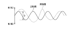
よって、所定期間(例えば数十秒)に撮影された遠赤外画像における呼吸部の温度は、呼吸に伴い変動する。呼吸状態検出手段45は、呼吸部の温度変動情報すなわち遠赤外画像における呼吸部の輝度変動情報から、ドライバの呼吸周期、呼吸の深さ、呼吸速度等の呼吸状態を検出する。呼吸周期は、図8に示すような呼吸部の輝度の変化曲線において、例えば山と山との間隔又は谷と谷との間隔とする。また、呼吸の深さは、図8に示すような呼吸部の輝度の変化曲線において、例えば山と谷との輝度の差分量Dとする。
Therefore, the temperature of the breathing part in the far-infrared image captured during a predetermined period (for example, several tens of seconds) varies with breathing. The breathing
ただし、マスク検出手段43によりドライバの鼻及び口を覆うマスクが検出された場合には、呼吸状態検出手段45は、検出されたマスクを呼吸部として、マスクの温度変動情報から呼吸状態を検出する。
However, when a mask covering the driver's nose and mouth is detected by the
マスク検出手段43は、所定期間に撮影された遠赤外画像からマスクを検出する。近赤外画像では、マスクと肌と境界線を抽出してマスクを検出することは困難である。これに対して、遠赤外画像では、図5に示すように、呼吸に伴いマスクにおいて鼻や口を覆う部分の温度が全体的に変動するため、所定期間における遠赤外画像からマスクを検出することができる。マスク検出手段43は、顔の下部において、通常の鼻領域Nや口領域Mよりも広い領域で温度が変動している場合に、温度の変動領域をマスクとして検出する。
The
さらに、呼吸状態検出手段45は、顔向き検出手段48により検出されたドライバの顔向きが、遠赤外カメラ11に対して鼻腔部の見えない向きであった場合に、誤検出を防止するため呼吸状態の検出を停止する。例えば、顔が大きく下又は上に傾いている場合には鼻腔部が見えないため、呼吸状態検出手段45は、このような場合には呼吸状態の検出を停止する。顔向き検出手段48は、近赤外画像からドライバの顔向きを検出する。詳しくは、顔向き検出手段48は、近赤外画像において認識した顔の部品の配置に基づいて顔向きを検出する。
Further, the breathing
瞬目状態検出手段46は、眼部の温度変動情報から瞬目状態を検出する。眼球の表面温度は、瞼の表面温度よりも低い。そのため、ドライバが眼を開いている場合は、遠赤外画像の眼球部の輝度は低くなり暗く映る。また、ドライバが眼を閉じている場合は、遠赤外画像の眼球部の輝度は高くなり明るく映る。 The blink state detection means 46 detects the blink state from the temperature variation information of the eye part. The surface temperature of the eyeball is lower than the surface temperature of the eyelid. Therefore, when the driver opens his eyes, the brightness of the eyeball part of the far-infrared image is lowered and appears dark. Further, when the driver closes his eyes, the brightness of the eyeball part of the far-infrared image becomes higher and appears brighter.
よって、所定期間に撮影された遠赤外画像における眼領域Er,Elの温度は、瞬きに伴い変動する。瞬目状態検出手段46は、眼領域Er,Elの温度変動情報すなわち遠赤外画像における眼領域Er,Elの輝度変動情報から、ドライバの瞬目周期、継続閉眼時間等の瞬目状態を検出する。瞬目周期は、眼領域Er,Elの輝度の変化曲線において、例えば山と山との間隔又は谷と谷との間隔とする。 Therefore, the temperatures of the eye regions Er and El in the far-infrared image captured during a predetermined period vary with blinking. The blink state detection means 46 detects the blink state such as the blink cycle of the driver, the continuous eye closure time, etc. from the temperature variation information of the eye regions Er and El, that is, the luminance variation information of the eye regions Er and El in the far-infrared image. To do. The blink cycle is, for example, the interval between the peaks or the valleys or the interval between the valleys in the luminance change curves of the eye regions Er and El.
ただし、眼鏡検出手段44によりドライバの眼鏡が検出された場合には、瞬目状態検出手段46は、図7に示すように、近赤外画像からドライバの眼の開度である開眼度を検出し、検出した開眼度の変動から瞬目状態を検出する。詳しくは、瞬目状態検出手段46は、近赤外画像から上下瞼の輪郭を抽出し、抽出した上瞼の輪郭と下瞼の輪郭との間隔や輪郭の形状から開眼度を検出する。
However, when the eyeglasses of the driver are detected by the
眼鏡検出手段44は、遠赤外画像からドライバの眼鏡を検出する。遠赤外画像では、図6に示すように、眼鏡部分はその他の顔部分よりも常に暗く映る。よって、眼鏡検出手段44は、遠赤外画像において、顔の上部で、常に低温部分が存在する場合に、低温部分を眼鏡として検出する。 The eyeglass detection means 44 detects the eyeglasses of the driver from the far infrared image. In the far-infrared image, as shown in FIG. 6, the spectacle portion always appears darker than the other face portions. Therefore, the spectacles detection means 44 detects a low-temperature part as spectacles, when a low-temperature part always exists in the upper part of a face in a far-infrared image.
状態判定手段47は、遠赤外カメラ11により所定期間に撮影された遠赤外画像に基づいて、ドライバの異常状態を判定する。詳しくは、状態判定手段47は、ドライバの呼吸状態及び瞬目状態に基づいて、ドライバの異常状態を判定する。
The
図8に示すように、ドライバが正常状態の場合には、呼吸の周期や深さは安定した略一定値となる。一方、ドライバが異常状態の場合には、呼吸の周期や深さは正常状態から変化して不安定に変動するものとなる。状態判定手段47は、呼吸周期の変動や呼吸の深さの変動に基づいて、ドライバの異常状態を判定する。
As shown in FIG. 8, when the driver is in a normal state, the breathing cycle and depth are stable and substantially constant values. On the other hand, when the driver is in an abnormal state, the breathing cycle and depth change from the normal state and vary in an unstable manner. The
また、図9に示すように、ドライバが正常状態の場合には、瞬目の周期や平均閉眼時間は安定した略一定値となる。一方、ドライバが異常状態の場合には、瞬目周期や平均閉眼時間は正常状態から変化して不安定に変動するものとなる。状態判定手段47は、瞬目周期の変動や平均閉眼時間の変動や半眼状態の継続など開眼度の変動に基づいて、ドライバの異常状態を判定する。半眼の検出は、眼探索領域内の明暗の内、暗い部分の領域の面積変動から求められる。 Further, as shown in FIG. 9, when the driver is in a normal state, the blinking cycle and the average eye-closing time are stable and substantially constant values. On the other hand, when the driver is in an abnormal state, the blinking cycle and the average eye-closing time change from the normal state and vary in an unstable manner. The state determination means 47 determines the abnormal state of the driver based on the fluctuation of the eye opening degree such as the fluctuation of the blink period, the fluctuation of the average eye-closing time, and the continuation of the half-eye state. The detection of the half eye is obtained from the area variation of the dark portion of the light search area in the eye search area.
次に、ドライバの異常状態を判定する処理手順について、図10のフローチャートを参照して説明する。本処理手順は、ECU20が繰り返し実行する。
Next, a processing procedure for determining the abnormal state of the driver will be described with reference to the flowchart of FIG. This processing procedure is repeatedly executed by the
まず、近赤外カメラ12により撮影された近赤外画像を取得するとともに(S10)、遠赤外カメラ11により撮影された遠赤外画像を取得する(S11)。S10とS11はほぼ同じタイミングであればよく順番は逆となっても問題ない。また、遠赤外カメラ11はその性格上、撮像毎ではないが時々はシャッタによりリセットする必要があるため、フレーム抜けが発生する可能性があるが、そこは適宜適切な処理をする。
First, a near-infrared image photographed by the near-
続いて、S10で取得した近赤外画像から、顔の部品すなわち眼、鼻、口を検出する。詳しくは、近赤外画像において顔の部品を認識し、顔の部品の位置情報を取得する(S12)。続いて、S12で検出した顔の部品の配置に基づいて、顔の位置及び顔向きを検出する(S13)。検出した顔の位置が遠赤外画像内に入らない位置の場合は、遠赤外画像に基づいた処理(S14〜S17)は実行しない。 Subsequently, face parts, that is, eyes, nose, and mouth are detected from the near-infrared image acquired in S10. Specifically, the facial component is recognized in the near-infrared image, and the positional information of the facial component is acquired (S12). Then, based on the arrangement of the facial parts detected in S12, the face position and face orientation are detected (S13). If the detected face position is not within the far infrared image, the processing based on the far infrared image (S14 to S17) is not executed.
続いて、S13で検出した顔向きが、鼻腔部が見える顔向きか否か判定する(S14)。鼻腔部が見える顔向きの場合は(S14:YES)、S11で取得した遠赤外画像に基づいて呼吸状態検出を行う(S15)。呼吸状態検出の処理手順の詳細は後述する。一方、鼻腔部が見えない顔向きの場合は(S14:NO)、呼吸状態検出を行わないで、眼鏡検出に進む。 Subsequently, it is determined whether or not the face direction detected in S13 is a face direction in which the nasal cavity portion can be seen (S14). If the face is facing the nasal cavity (S14: YES), the respiratory state is detected based on the far-infrared image acquired in S11 (S15). Details of the processing procedure of the respiratory state detection will be described later. On the other hand, when the face is facing the nasal cavity (S14: NO), the flow proceeds to eyeglass detection without detecting the respiratory state.
続いて、S11で取得した遠赤外線画像から眼鏡を検出したか否か判定する(S16)。眼鏡を検出していない場合は(S16:NO)、S11で取得した遠赤外画像に基づいて瞬目状態検出を行う(S17)。瞬目状態検出の処理手順の詳細は後述する。S17の処理の後、S10で取得した近赤外画像から、ドライバの眼の開眼度を検出する(S18)。一方、眼鏡を検出した場合は(S16:YES)、S11で取得した遠赤外画像に基づいた瞬目状態検出を行わないで、S10で取得した近赤外画像から、ドライバの眼の開眼度の検出を行う(S18)。 Subsequently, it is determined whether or not glasses are detected from the far-infrared image acquired in S11 (S16). When glasses are not detected (S16: NO), blink state detection is performed based on the far-infrared image acquired in S11 (S17). Details of the blink state detection processing procedure will be described later. After the process of S17, the eye opening degree of the driver's eye is detected from the near-infrared image acquired in S10 (S18). On the other hand, when eyeglasses are detected (S16: YES), the eye-opening degree of the driver's eyes is determined from the near-infrared image acquired in S10 without performing the blink state detection based on the far-infrared image acquired in S11. Is detected (S18).
S10で取得した近赤外画像から、ドライバの眼の開眼度を検出するとき、S16で眼鏡を検出している場合は、S16で検出された眼鏡の有無および位置情報を用いることで、眼鏡のフレームを眼の輪郭として誤検出することを防止する。続いて、開眼度の履歴及びS18で検出した開眼度を用いて、所定期間における開眼度の変動を算出し、算出した開眼度の変動から瞬目周期を検出する(S19)。 When detecting the eye open degree of the driver's eye from the near-infrared image acquired in S10, if the spectacles are detected in S16, the presence / absence and position information of the spectacles detected in S16 is used. This prevents erroneous detection of the frame as an eye contour. Subsequently, using the eye opening degree history and the eye opening degree detected in S18, the fluctuation of the eye opening degree in a predetermined period is calculated, and the blink cycle is detected from the calculated eye opening degree fluctuation (S19).
続いて、S15で検出した呼吸周期、及び/又は、S17及び/又はS19で検出した瞬目周期に基づいて、ドライバが異常状態か否か判定する(S20)。例えば、検出した呼吸周期及び瞬目周期を学習しておき、検出した呼吸周期と呼吸周期の学習値との差が呼吸閾値よりも大きい場合、又は検出した瞬目周期と瞬目周期の学習値との差が瞬目閾値よりも大きい場合に、ドライバが異常状態と判定する。あるいは、検出した呼吸周期の分散値が呼吸分散閾値よりも大きい場合、又は検出した瞬目周期の分散値が瞬目分散閾値よりも大きい場合に、ドライバが異常状態と判定してもよい。また、検出した呼吸周期及び瞬目周期からそれぞれ異常度合を算出するとともに、それぞれ算出した異常度合を統合し、統合した異常度合と異常閾値とを比較して、ドライバの異常状態を判定してもよい。なお、S15で呼吸状態を検出していない場合は、瞬目状態のみに基づいてドライバの異常状態を判定する。 Subsequently, it is determined whether or not the driver is in an abnormal state based on the respiratory cycle detected in S15 and / or the blink cycle detected in S17 and / or S19 (S20). For example, when the detected breathing cycle and blink cycle are learned and the difference between the detected breathing cycle and the learning value of the breathing cycle is greater than the breathing threshold, or the detected blinking cycle and blinking cycle learning value When the difference between is greater than the blink threshold, the driver determines that the state is abnormal. Alternatively, the driver may determine that the abnormal state is present when the detected variance value of the respiratory cycle is greater than the respiratory variance threshold value or when the detected blink interval variance value is greater than the blink variance threshold value. In addition, the degree of abnormality is calculated from the detected respiratory cycle and blink period, and the calculated abnormality degree is integrated, and the abnormal state of the driver is determined by comparing the integrated abnormality degree and the abnormality threshold. Good. If the respiratory state is not detected in S15, the driver's abnormal state is determined based only on the blink state.
さらに、S13で検出した顔向きに基づいて、ドライバが異常状態か否か判定する(S20)。ドライバの顔向きが脇見をしている向きの場合は、ドライバが異常状態と判定する。 Further, based on the face orientation detected in S13, it is determined whether or not the driver is in an abnormal state (S20). If the driver's face is looking aside, the driver determines that it is in an abnormal state.
S20でドライバが正常状態と判定した場合は(S20:NO)、本処理を終了する。S20でドライバが異常状態と判定した場合は(S20:YES)、アクチュエーション部60の各装置61〜63に制御信号を送信して、各装置61〜63を駆動させる(S21)。
If it is determined in S20 that the driver is in a normal state (S20: NO), this process ends. When the driver determines that the driver is in an abnormal state in S20 (S20: YES), a control signal is transmitted to each device 61-63 of the
続いて、S11〜S20の処理を繰り返して、ドライバが正常状態に復帰したか否か判定する(S22)。ドライバが正常状態に復帰した場合は(S22:YES)、本処理を終了する。ドライバが異常状態のままである場合は(S22:NO)、車両緊急停止装置64へ制御信号を送信して、車両を緊急停止させる(S23)。以上で本処理を終了する。
Subsequently, the processes of S11 to S20 are repeated to determine whether or not the driver has returned to a normal state (S22). If the driver returns to the normal state (S22: YES), this process is terminated. If the driver remains in an abnormal state (S22: NO), a control signal is transmitted to the vehicle
次に、呼吸状態検出の処理手順について、図11のサブルーチンを参照して説明する。まず、S11で取得した遠赤外画像からマスクを検出したか否か判定する(S151)。 Next, the processing procedure for detecting the respiratory state will be described with reference to the subroutine of FIG. First, it is determined whether a mask is detected from the far-infrared image acquired in S11 (S151).
マスクを検出していない場合は(S151:NO)、S12で取得した鼻の位置情報を用いて、S11で取得した遠赤外画像から鼻腔部の探索領域である鼻領域Nを抽出する(S152)。続いて、S152で抽出した鼻領域Nを探索して、鼻腔部の輪郭を検出する(S153)。2つの鼻腔部のうちの一方が鼻詰まりになっている場合もあるため、鼻腔部は左右それぞれ検出する。続いて、S153で検出した左右の鼻腔部の輪郭内である鼻腔部の画素値を平均して、画素値の平均値を左右それぞれ算出する(S154)。続いて、左右の画素平均値の履歴、及びS154で算出した左右の画素平均値を用いて、所定期間における左右の画素平均値の変動を算出し、呼吸周期を検出する。左右の鼻腔部それぞれにつて呼吸周期を検出するため、一方の鼻腔部が鼻詰まりになっていても、呼吸周期を検出できる。この後、S16の処理に進む。 When the mask is not detected (S151: NO), the nose region N that is the search region of the nasal cavity is extracted from the far-infrared image acquired in S11 using the nose position information acquired in S12 (S152). ). Subsequently, the nose region N extracted in S152 is searched to detect the outline of the nasal cavity (S153). Since one of the two nasal cavity parts may be clogged, the nasal cavity part is detected on each of the left and right sides. Subsequently, the pixel values of the nasal cavity portions within the contours of the left and right nasal cavity portions detected in S153 are averaged, and the average value of the pixel values is calculated for each of the left and right sides (S154). Subsequently, using the history of the left and right pixel average values and the left and right pixel average values calculated in S154, the fluctuation of the left and right pixel average values in a predetermined period is calculated, and the respiratory cycle is detected. Since the respiratory cycle is detected for each of the left and right nasal cavity portions, the respiratory cycle can be detected even if one of the nasal cavity portions is clogged. Thereafter, the process proceeds to S16.
なお、所定期間における左右の画素平均値がほとんど変動していない場合は、ドライバが鼻呼吸ではなく口呼吸をしていると判断する。この場合、S11で取得した遠赤外画像から口領域Mを抽出し、口領域Mを探索して、口の輪郭を検出する。そして、口内部の画素平均値を算出するとともに、所定期間における口内部の画素平均値の変動を算出し、呼吸周期を検出する。 Note that if the left and right pixel average values in the predetermined period hardly fluctuate, it is determined that the driver is breathing mouth instead of nasal breathing. In this case, the mouth region M is extracted from the far-infrared image acquired in S11, the mouth region M is searched, and the contour of the mouth is detected. And while calculating the pixel average value inside a mouth, the fluctuation | variation of the pixel average value inside a mouth in a predetermined period is calculated, and a respiratory cycle is detected.
また、マスクを検出している場合は(S151:YES)は、検出したマスクの鼻や口を覆っている部分について画素値の平均値を算出する(S155)。続いて、マスクの輝度平均値の履歴、及びS155で算出したマスク全体または、マスク内で鼻や口が存在すると推定される領域の画素値の平均値を用いて、所定時間における画素平均値の変動を算出し、呼吸周期を検出する。この後、S16の処理に進む。 When a mask is detected (S151: YES), an average value of pixel values is calculated for a portion of the detected mask covering the nose and mouth (S155). Subsequently, using the average luminance value of the mask and the average value of the pixel values of the entire mask calculated in S155 or the area where the nose and mouth are estimated to be present in the mask, Change is calculated and respiratory cycle is detected. Thereafter, the process proceeds to S16.
次に、瞬目状態検出の処理手順について、図12のサブルーチンを参照して説明する。まず、S12で取得した眼の位置情報を用いて、S11で取得した遠赤外画像から眼部の探索領域である眼領域El,Erを抽出する(S171)。続いて、S171で抽出した眼領域El,Erを探索して、左右の眼の輪郭を検出する(S172)。続いて、S172で検出した左右の眼の輪郭内である左右の眼部の画素値の平均値をそれぞれ算出する(S173)。続いて、眼部の画素平均値の履歴、及びS173で算出した眼部の画素平均値を用いて、所定期間における眼部の画素平均値の変動を算出し、瞬目周期を検出する(S174)。この後、S20の処理に進む。 Next, the blinking state detection processing procedure will be described with reference to the subroutine of FIG. First, eye regions El and Er, which are eye region search regions, are extracted from the far-infrared image acquired in S11 using the eye position information acquired in S12 (S171). Subsequently, the eye regions El and Er extracted in S171 are searched to detect the right and left eye contours (S172). Subsequently, the average value of the pixel values of the left and right eyes within the contours of the left and right eyes detected in S172 is calculated (S173). Subsequently, using the history of the average pixel value of the eye and the average pixel value of the eye calculated in S173, the variation of the average pixel value of the eye during a predetermined period is calculated, and the blink cycle is detected (S174). ). Thereafter, the process proceeds to S20.
以上説明した本実施形態によれば、以下の効果を奏する。 According to this embodiment described above, the following effects are obtained.
・遠赤外カメラ11により、ドライバの顔表面の温度分布を表す遠赤外画像が撮影される。ドライバが異常状態になると、ドライバの顔の温度分布はドライバが正常状態のときとは局所的には異なる変動をする。よって、所定期間に逐次撮影された遠赤外画像に基づいて、ドライバの異常状態が判定できる。また、遠赤外カメラ11は外乱光の影響を受けにくい。さらに、遠赤外カメラ11は非接触センサであるため、安定してドライバの顔画像を撮影できる。したがって、所定期間におけるドライバの顔の遠赤外画像から、高精度に安定してドライバの異常状態を判定できる。 The far infrared camera 11 captures a far infrared image representing the temperature distribution on the driver's face. When the driver enters an abnormal state, the temperature distribution of the driver's face varies locally differently from when the driver is in a normal state. Therefore, the abnormal state of the driver can be determined based on the far-infrared images that are sequentially photographed during the predetermined period. Further, the far-infrared camera 11 is not easily affected by ambient light. Furthermore, since the far-infrared camera 11 is a non-contact sensor, it can stably capture a driver's face image. Therefore, the abnormal state of the driver can be determined with high accuracy and stability from the far-infrared image of the driver's face in a predetermined period.
・呼吸の周期に対応して鼻腔部又は口内部の温度は変動する。よって、ドライバの鼻腔部又は口内部の温度変動情報からドライバの呼吸状態を検出できる。そして、検出したドライバの呼吸状態からドライバの異常状態を判定できる。 ・ The temperature of the nasal cavity or the mouth fluctuates according to the respiratory cycle. Therefore, the respiratory state of the driver can be detected from the temperature fluctuation information inside the driver's nasal cavity or mouth. Then, the abnormal state of the driver can be determined from the detected respiratory state of the driver.
・瞬目周期に対応して眼部の温度は変動する。よって、ドライバの眼部の温度変動情報からドライバの瞬目状態を検出できる。そして、検出したドライバの瞬目状態からドライバの異常状態を判定できる。 ・ Eye temperature fluctuates corresponding to the blink cycle. Therefore, the blink state of the driver can be detected from the temperature fluctuation information of the driver's eyes. Then, the abnormal state of the driver can be determined from the detected blink state of the driver.
・ドライバが異常状態になると、呼吸周期が正常時の周期から変化したり、呼吸周期がばらついたりする。よって、呼吸周期の変動に基づいて、ドライバの異常状態を判定することができる。 ・ If the driver becomes abnormal, the respiratory cycle may change from the normal cycle or the respiratory cycle may vary. Therefore, the abnormal state of the driver can be determined based on the change in the respiratory cycle.
・ドライバが異常状態となると、瞬目周期が正常時の周期から変化したり、瞬目周期がばらついたりする。よって、瞬目周期の変動に基づいて、ドライバの異常状態を判定することができる。 -When the driver enters an abnormal state, the blink cycle changes from the normal cycle or the blink cycle varies. Therefore, the abnormal state of the driver can be determined based on the fluctuation of the blink cycle.
・遠赤外画像は画像としては明瞭ではないため、通常の画像処理にて顔の部品を認識することは困難である。一方、近赤外画像は、顔の部品のエッジ点を抽出して顔の部品を認識しやすい。そこで、近赤外カメラ12により撮影された近赤外画像から顔の部品が認識されて、顔の部品の位置情報が取得される。そして、近赤外画像から取得された顔の部品の位置情報を用いて、遠赤外画像における眼領域El,Er、鼻領域N、及び口領域Mが抽出される。このように、遠赤外カメラ11と近赤外カメラ12を組み合わせたマルチモーダルな検出方法を用いることにより、遠赤外カメラ11のみを用いた場合よりも高精度にドライバの呼吸状態及び瞬目状態を検出できる。
-Since a far-infrared image is not clear as an image, it is difficult to recognize facial parts by normal image processing. On the other hand, the near-infrared image easily recognizes a facial part by extracting an edge point of the facial part. Therefore, the facial part is recognized from the near-infrared image photographed by the near-
・一般的に近赤外画像からマスクを検出することは困難であるが、遠赤外画像では呼吸に伴いマスクの鼻や口を覆う部分の温度が全体的に変動するため、マスクを高精度に検出することができる。 ・ In general, it is difficult to detect a mask from a near-infrared image. However, in a far-infrared image, the temperature of the part covering the nose and mouth of the mask varies as a whole with breathing, so the mask is highly accurate. Can be detected.
・遠赤外画像では、眼鏡はその他の顔部分よりも常に暗くなる。そのため、遠赤外画像から眼鏡を高精度に検出することができる。 ・ In far-infrared images, glasses are always darker than other face parts. Therefore, the glasses can be detected from the far infrared image with high accuracy.
・ドライバがマスクを着用している場合は、鼻領域N又は口領域Mを抽出できないが、呼吸に伴いマスクが全体的に温度変動する。そこで、マスクが検出された場合は、マスクを呼吸部とすることで、マスクの温度変動から呼吸状態を検出できる。 When the driver is wearing a mask, the nose region N or the mouth region M cannot be extracted, but the temperature of the mask varies as a whole with breathing. Therefore, when a mask is detected, the respiratory state can be detected from the temperature variation of the mask by using the mask as a breathing unit.
・ドライバが眼鏡を着用している場合は、遠赤外画像を用いて眼部の温度変動から瞬目状態を検出することができない。そこで、この場合は、近赤外画像から開眼度を検出することにより、開眼度の変動から瞬目状態を検出できる。 -When the driver is wearing glasses, the blink state cannot be detected from the temperature variation of the eye using a far-infrared image. Therefore, in this case, by detecting the eye opening degree from the near-infrared image, the blink state can be detected from the fluctuation of the eye opening degree.
・遠赤外画像から検出された眼鏡の位置情報を用いて、近赤外画像からドライバの眼の開眼度を検出することにより、眼鏡のフレームを眼の輪郭と誤検出することを防止できる。 By detecting the eye opening degree of the driver's eye from the near-infrared image using the position information of the eyeglass detected from the far-infrared image, it is possible to prevent erroneous detection of the eyeglass frame as the eye contour.
(他の実施形態)
・呼吸状態検出手段45は、ドライバの異常判定に用いる指標として、呼吸の深さや呼吸速度等の呼吸周期以外の呼吸状態を検出してもよい。
(Other embodiments)
The breathing
・瞬目状態検出手段46は、ドライバの異常判定に用いる指標として、継続閉眼時間や平均開眼時間等の瞬目状態を検出してもよい。 The blink state detection means 46 may detect blink states such as a continuous eye closing time and an average eye opening time as an index used for driver abnormality determination.
・呼吸状態及び瞬目状態のいずれか一方のみを検出し、いずれか一方のみに基づいて、ドライバの異常状態を判定するようにしてもよい。 -Only one of the breathing state and the blink state may be detected, and the abnormal state of the driver may be determined based on only one of them.
・ECU20の状態判定部40は、遠赤外画像において、所定期間における温度の変動量が閾値よりも大きい温度変動領域を検出する変動領域検出手段を備えていてもよい。そして、位置取得手段41は、近赤外画像において、変動領域検出手段により検出された温度変動領域を用いて認識領域を抽出し、抽出した認識領域において顔の部品の認識処理を行ってもよい。このようにすると、認識処理の負荷を軽減できる。
The
・ドライバ状態判定装置10は、近赤外カメラ12を備えていなくてもよい。遠赤外カメラ11により撮影された遠赤外画像のみを用いて、ドライバの異常状態を判定してもよい。この場合、遠赤外画像の時間変化をみて、温度が高低を繰り返している左右一対の部分を、眼部及び鼻腔部として検出する。また、ドライバが口呼吸をしているときには、眼よりも下で温度が高低を繰り返している部分を口内部として検出する。
The driver
10…ドライバ状態判定装置、11…遠赤外カメラ、20…ECU、47…状態判定手段。
DESCRIPTION OF
Claims (10)
前記遠赤外カメラにより所定期間に逐次撮影された前記遠赤外画像に基づいて、前記ドライバの異常状態を判定する状態判定手段(47)と、
前記遠赤外画像における前記ドライバの眼部の温度変動情報から前記ドライバの瞬目状態を検出する瞬目状態検出手段(46)と、
前記遠赤外画像から前記ドライバの眼鏡を検出する眼鏡検出手段(44)と、
前記ドライバの顔の近赤外画像を撮影する近赤外カメラと、を備え、
前記瞬目状態検出手段は、前記瞬目状態として瞬目周期を検出し、前記眼鏡検出手段により前記遠赤外画像から前記眼鏡が検出された場合に、前記近赤外画像から前記ドライバの開眼度を検出し、検出した前記開眼度の変動から前記瞬目周期を検出し、
前記状態判定手段は、前記瞬目状態検出手段により検出された前記瞬目周期の変動に基づいて、前記ドライバの異常状態を判定するドライバ状態判定装置。 A far-infrared camera (11) that captures a far-infrared image representing a temperature distribution of the driver's face surface, which is a face image of a driver of the vehicle;
State determination means (47) for determining an abnormal state of the driver based on the far-infrared images sequentially captured by the far-infrared camera for a predetermined period;
Blink state detection means (46) for detecting blink state of the driver from temperature variation information of the eye of the driver in the far-infrared image;
Glasses detecting means (44) for detecting the driver's glasses from the far-infrared image;
A near-infrared camera that captures a near-infrared image of the driver's face,
The blink state detection unit detects a blink cycle as the blink state, and when the glasses are detected from the far-infrared image by the glasses detection unit, the driver's eye opening from the near-infrared image Detecting the degree of blinking, detecting the blink cycle from the detected variation in the degree of eye opening,
The state determination unit is a driver state determination unit that determines an abnormal state of the driver based on a change in the blink cycle detected by the blink state detection unit.
前記状態判定手段は、前記呼吸状態検出手段により検出された前記呼吸状態に基づいて、前記ドライバの異常状態を判定する請求項1に記載のドライバ状態判定装置。 Respiratory state detection means (45) for detecting a respiratory state of the driver from temperature variation information of the respiratory part, with the nasal cavity or the mouth inside the driver in the far-infrared image as a respiratory part,
The driver state determination device according to claim 1, wherein the state determination unit determines an abnormal state of the driver based on the respiratory state detected by the respiratory state detection unit.
前記状態判定手段は、前記呼吸周期の変動に基づいて、前記ドライバの異常状態を判定する請求項2に記載のドライバ状態判定装置。 The respiratory state detection means detects a respiratory cycle as the respiratory state,
The driver state determination device according to claim 2, wherein the state determination unit determines an abnormal state of the driver based on a change in the respiratory cycle.
前記近赤外カメラにより撮影された前記近赤外画像から前記ドライバの鼻又は口を認識して、認識した前記鼻又は口の位置情報を取得する位置取得手段(41)と、
前記位置取得手段により取得された前記位置情報を用いて、前記遠赤外画像において前記呼吸部を探索する探索領域(N,M)を抽出する領域抽出手段(42)と、を備える請求項2又は3に記載のドライバ状態判定装置。 A near-infrared camera (12) that captures a near-infrared image of the driver's face;
Position acquisition means (41) for recognizing the driver's nose or mouth from the near-infrared image photographed by the near-infrared camera and acquiring the recognized nose or mouth position information;
The area extraction means (42) which extracts the search area | region (N, M) which searches the said respiratory part in the said far-infrared image using the said positional information acquired by the said position acquisition means. Or the driver state determination device according to 3.
前記近赤外カメラにより撮影された前記近赤外画像から前記ドライバの顔向きを検出する顔向き検出手段(48)と、を備え、
前記呼吸状態検出手段は、前記顔向き検出手段により検出された前記ドライバの顔向きが、前記遠赤外カメラに対して前記鼻腔部の見えない向きである場合に、前記呼吸状態の検出を停止する請求項2〜6のいずれかに記載のドライバ状態判定装置。 A near-infrared camera that captures a near-infrared image of the driver's face;
A face orientation detection means (48) for detecting the face orientation of the driver from the near-infrared image captured by the near-infrared camera,
The breathing state detection unit stops the detection of the breathing state when the face direction of the driver detected by the face direction detection unit is a direction in which the nasal cavity portion cannot be seen with respect to the far-infrared camera. The driver state determination apparatus according to any one of claims 2 to 6.
前記近赤外カメラにより撮影された前記近赤外画像から前記ドライバの眼を認識して、認識した前記眼の位置情報を取得する位置取得手段(41)と、
前記位置取得手段により取得された前記位置情報に基づいて、前記遠赤外画像において前記眼部を探索する探索領域(El,Er)を抽出する領域抽出手段と、を備える請求項1〜7のいずれかに記載のドライバ状態判定装置。 A near-infrared camera (12) that captures a near-infrared image of the driver's face;
Position acquisition means (41) for recognizing the eyes of the driver from the near-infrared image photographed by the near-infrared camera and acquiring the recognized position information of the eyes;
The area extraction means which extracts the search area | region (El, Er) which searches the said eye part in the said far-infrared image based on the said positional information acquired by the said position acquisition means . The driver state determination apparatus in any one .
前記位置取得手段は、前記変動領域検出手段により検出された前記温度変動領域を用いて認識処理を行う請求項4又は8に記載のドライバ状態判定装置。 In the far-infrared image, a fluctuation region detection means for detecting a temperature fluctuation region in which the temperature fluctuation amount in the predetermined period is larger than a threshold value;
The driver state determination apparatus according to claim 4 or 8 , wherein the position acquisition unit performs a recognition process using the temperature variation region detected by the variation region detection unit.
Priority Applications (4)
| Application Number | Priority Date | Filing Date | Title |
|---|---|---|---|
| JP2014184906A JP6442942B2 (en) | 2014-09-11 | 2014-09-11 | Driver status determination device |
| US15/506,064 US10165971B2 (en) | 2014-09-11 | 2015-08-03 | Driver state determination apparatus |
| CN201580048564.5A CN106716515B (en) | 2014-09-11 | 2015-08-03 | Driver condition assessment device |
| PCT/JP2015/003904 WO2016038784A1 (en) | 2014-09-11 | 2015-08-03 | Driver state determination apparatus |
Applications Claiming Priority (1)
| Application Number | Priority Date | Filing Date | Title |
|---|---|---|---|
| JP2014184906A JP6442942B2 (en) | 2014-09-11 | 2014-09-11 | Driver status determination device |
Related Child Applications (1)
| Application Number | Title | Priority Date | Filing Date |
|---|---|---|---|
| JP2018222792A Division JP6747493B2 (en) | 2018-11-28 | 2018-11-28 | Driver status determination device |
Publications (3)
| Publication Number | Publication Date |
|---|---|
| JP2016057944A JP2016057944A (en) | 2016-04-21 |
| JP2016057944A5 JP2016057944A5 (en) | 2016-12-22 |
| JP6442942B2 true JP6442942B2 (en) | 2018-12-26 |
Family
ID=55458560
Family Applications (1)
| Application Number | Title | Priority Date | Filing Date |
|---|---|---|---|
| JP2014184906A Active JP6442942B2 (en) | 2014-09-11 | 2014-09-11 | Driver status determination device |
Country Status (4)
| Country | Link |
|---|---|
| US (1) | US10165971B2 (en) |
| JP (1) | JP6442942B2 (en) |
| CN (1) | CN106716515B (en) |
| WO (1) | WO2016038784A1 (en) |
Families Citing this family (31)
| Publication number | Priority date | Publication date | Assignee | Title |
|---|---|---|---|---|
| JP6631783B2 (en) * | 2015-11-19 | 2020-01-15 | エア・ウォーター・バイオデザイン株式会社 | Measuring system and measuring method for measuring life activity caused by respiration of subject |
| JP6658306B2 (en) * | 2016-05-27 | 2020-03-04 | トヨタ自動車株式会社 | Spoken dialogue system and utterance timing determination method |
| JP6598748B2 (en) * | 2016-08-26 | 2019-10-30 | 任天堂株式会社 | Information processing system, information processing program, information processing apparatus, and information processing method |
| US11279279B2 (en) * | 2016-12-22 | 2022-03-22 | Sri International | Driver monitoring and response system |
| CN107280673B (en) * | 2017-06-02 | 2019-11-15 | 南京理工大学 | A kind of infrared imaging breath signal detection method based on key-frame extraction technique |
| CN110809430B (en) * | 2017-07-19 | 2023-07-04 | 松下知识产权经营株式会社 | Drowsiness estimation device and wake induction device |
| CN107480629A (en) * | 2017-08-11 | 2017-12-15 | 常熟理工学院 | A kind of method for detecting fatigue driving and device based on depth information |
| CN111033590B (en) * | 2017-08-18 | 2022-09-09 | 索尼公司 | Vehicle travel control device, vehicle travel control method, and program |
| CN108036476B (en) * | 2017-12-08 | 2020-10-09 | 安徽诚意电气科技有限公司 | Air conditioner |
| CN108050675B (en) * | 2017-12-08 | 2020-11-24 | 太仓米吉纺织有限公司 | Air conditioner control method |
| CN108061364B (en) * | 2017-12-08 | 2020-12-01 | 太仓米吉纺织有限公司 | Air conditioner control method |
| CN108245154B (en) * | 2018-01-24 | 2020-10-09 | 福州大学 | Method for accurately determining blink interval in electroencephalogram or electrooculogram by using abnormal value detection |
| JP6981277B2 (en) * | 2018-01-26 | 2021-12-15 | 富士フイルムビジネスイノベーション株式会社 | Detection device and detection program |
| US10867195B2 (en) * | 2018-03-12 | 2020-12-15 | Microsoft Technology Licensing, Llc | Systems and methods for monitoring driver state |
| JP7180228B2 (en) * | 2018-09-20 | 2022-11-30 | いすゞ自動車株式会社 | Vehicle monitoring device |
| KR102613205B1 (en) * | 2018-10-23 | 2023-12-14 | 현대자동차주식회사 | Vehicle and controlling method for the vehicle |
| JP2020077037A (en) * | 2018-11-05 | 2020-05-21 | 株式会社デンソー | Operation management device and operation management system |
| WO2020100584A1 (en) * | 2018-11-13 | 2020-05-22 | ソニー株式会社 | Information processing device, information processing method, and program |
| JP7251148B2 (en) * | 2019-01-09 | 2023-04-04 | コベルコ建機株式会社 | Operation control device for construction machinery |
| WO2020144807A1 (en) * | 2019-01-10 | 2020-07-16 | 三菱電機株式会社 | Respiration determination device, occupant state determination device, respiration determination method |
| CN109998496A (en) * | 2019-01-31 | 2019-07-12 | 中国人民解放军海军工程大学 | A kind of autonomous type body temperature automatic collection and respiratory monitoring system and method |
| JP2020149507A (en) * | 2019-03-14 | 2020-09-17 | 本田技研工業株式会社 | Occupant observation device |
| KR20210041915A (en) * | 2019-10-08 | 2021-04-16 | 현대자동차주식회사 | Apparatus and method for controlling alcohol interlock |
| JP7259793B2 (en) * | 2020-03-26 | 2023-04-18 | いすゞ自動車株式会社 | Driving support device |
| US20210344852A1 (en) * | 2020-05-04 | 2021-11-04 | Rebellion Photonics, Inc. | Apparatuses, systems, and methods for thermal imaging |
| FR3109876A1 (en) * | 2020-05-11 | 2021-11-12 | Valeo Systemes Thermiques | Disease detection system |
| US11945461B2 (en) | 2021-08-05 | 2024-04-02 | Hyundai Mobis Co., Ltd. | System for preventing drunk driving and method for controlling the same |
| CN114157807A (en) * | 2021-11-29 | 2022-03-08 | 江苏宏智医疗科技有限公司 | Image acquisition method and device and readable storage medium |
| JP7223194B1 (en) * | 2022-05-27 | 2023-02-15 | 株式会社エクサウィザーズ | Information processing method, computer program, information processing device and information processing system |
| DE102022206389A1 (en) * | 2022-06-24 | 2024-01-04 | Continental Engineering Services Gmbh | Detection system for monitoring the condition of the driver of a motor vehicle |
| DE102022206390A1 (en) * | 2022-06-24 | 2024-01-04 | Continental Engineering Services Gmbh | Method and vehicle control system for setting comfortable temperatures |
Family Cites Families (19)
| Publication number | Priority date | Publication date | Assignee | Title |
|---|---|---|---|---|
| JP3293308B2 (en) * | 1994-03-10 | 2002-06-17 | 三菱電機株式会社 | Person state detection device |
| US5689241A (en) * | 1995-04-24 | 1997-11-18 | Clarke, Sr.; James Russell | Sleep detection and driver alert apparatus |
| US6996256B2 (en) * | 2000-06-08 | 2006-02-07 | Honeywell International Inc. | Detection system and method using thermal image analysis |
| JP4325271B2 (en) * | 2003-05-12 | 2009-09-02 | 日産自動車株式会社 | Status detection device and status detection system |
| JP2007229218A (en) * | 2006-03-01 | 2007-09-13 | Toyota Motor Corp | Apparatus, system, and method for vigilance estimation |
| JP4677940B2 (en) * | 2006-03-27 | 2011-04-27 | トヨタ自動車株式会社 | Sleepiness detection device |
| JP2008027044A (en) * | 2006-07-19 | 2008-02-07 | Hino Motors Ltd | Caution device |
| JP4985428B2 (en) * | 2007-02-01 | 2012-07-25 | 株式会社デンソー | Driver management device and operation management system |
| US9129460B2 (en) * | 2007-06-25 | 2015-09-08 | Inthinc Technology Solutions, Inc. | System and method for monitoring and improving driver behavior |
| JP2009183560A (en) * | 2008-02-07 | 2009-08-20 | Kumamoto Technology & Industry Foundation | Apnea detection system |
| JP4727688B2 (en) | 2008-04-23 | 2011-07-20 | トヨタ自動車株式会社 | Awakening level estimation device |
| JP5326521B2 (en) * | 2008-11-26 | 2013-10-30 | 日産自動車株式会社 | Arousal state determination device and arousal state determination method |
| JP5323532B2 (en) * | 2009-02-24 | 2013-10-23 | 学校法人成蹊学園 | Respiration measurement method and respiration measurement device |
| CN101720026A (en) * | 2009-11-04 | 2010-06-02 | 厦门蓝斯通信有限公司 | Vehicle monitoring device |
| JP5680667B2 (en) * | 2009-12-02 | 2015-03-04 | タタ コンサルタンシー サービシズ リミテッドTATA Consultancy Services Limited | System and method for identifying driver wakefulness |
| JP5997871B2 (en) * | 2010-12-10 | 2016-09-28 | ティーケー ホールディングス インク.Tk Holdings Inc. | Vehicle driver monitoring system |
| JP5423724B2 (en) * | 2011-04-28 | 2014-02-19 | トヨタ自動車株式会社 | Driver status determination device |
| WO2013035704A1 (en) * | 2011-09-05 | 2013-03-14 | 富山県 | Dozing-off detection method and device |
| JP2013156707A (en) * | 2012-01-26 | 2013-08-15 | Nissan Motor Co Ltd | Driving support device |
-
2014
- 2014-09-11 JP JP2014184906A patent/JP6442942B2/en active Active
-
2015
- 2015-08-03 WO PCT/JP2015/003904 patent/WO2016038784A1/en active Application Filing
- 2015-08-03 CN CN201580048564.5A patent/CN106716515B/en active Active
- 2015-08-03 US US15/506,064 patent/US10165971B2/en active Active
Also Published As
| Publication number | Publication date |
|---|---|
| WO2016038784A1 (en) | 2016-03-17 |
| JP2016057944A (en) | 2016-04-21 |
| CN106716515A (en) | 2017-05-24 |
| US10165971B2 (en) | 2019-01-01 |
| CN106716515B (en) | 2019-06-07 |
| US20180116579A1 (en) | 2018-05-03 |
Similar Documents
| Publication | Publication Date | Title |
|---|---|---|
| JP6442942B2 (en) | Driver status determination device | |
| JP5109922B2 (en) | Driver monitoring device and program for driver monitoring device | |
| CN104200192B (en) | Driver's gaze detection system | |
| Yan et al. | Real-time driver drowsiness detection system based on PERCLOS and grayscale image processing | |
| JP6338701B2 (en) | Device, method and computer program for detecting instantaneous sleep | |
| Alshaqaqi et al. | Driver drowsiness detection system | |
| JP4793269B2 (en) | Sleepiness detection device | |
| JP6747493B2 (en) | Driver status determination device | |
| JP5177011B2 (en) | Eye opening degree identification device | |
| JP2008210239A (en) | Line-of-sight estimation device | |
| US9892333B2 (en) | Viewing area estimation device | |
| Ghosh et al. | Real time eye detection and tracking method for driver assistance system | |
| JP4840146B2 (en) | Sleepiness detection device | |
| JP2009219555A (en) | Drowsiness detector, driving support apparatus, drowsiness detecting method | |
| CN107507395A (en) | A kind of fatigue driving detecting system and method | |
| JP2019087170A (en) | Eyelid opening determination device and sleepiness detector | |
| RU2413632C2 (en) | Method to prevent driver falling asleep | |
| JP2008194309A (en) | Eye detector, nap detector, and method of eye detector | |
| Bergasa et al. | Visual monitoring of driver inattention | |
| JP4895874B2 (en) | Eye state determination device, eye state determination method, and eye state determination program | |
| JP2004192552A (en) | Eye opening/closing determining apparatus | |
| JP7240910B2 (en) | Passenger observation device | |
| Zeng et al. | A driving assistant safety method based on human eye fatigue detection | |
| JP4781292B2 (en) | Closed eye detection device, dozing detection device, closed eye detection method, and closed eye detection program | |
| Shah et al. | Yawning detection of driver drowsiness |
Legal Events
| Date | Code | Title | Description |
|---|---|---|---|
| A521 | Request for written amendment filed |
Free format text: JAPANESE INTERMEDIATE CODE: A523 Effective date: 20161102 |
|
| A621 | Written request for application examination |
Free format text: JAPANESE INTERMEDIATE CODE: A621 Effective date: 20170322 |
|
| A131 | Notification of reasons for refusal |
Free format text: JAPANESE INTERMEDIATE CODE: A131 Effective date: 20180327 |
|
| A521 | Request for written amendment filed |
Free format text: JAPANESE INTERMEDIATE CODE: A523 Effective date: 20180510 |
|
| TRDD | Decision of grant or rejection written | ||
| A01 | Written decision to grant a patent or to grant a registration (utility model) |
Free format text: JAPANESE INTERMEDIATE CODE: A01 Effective date: 20181030 |
|
| A61 | First payment of annual fees (during grant procedure) |
Free format text: JAPANESE INTERMEDIATE CODE: A61 Effective date: 20181112 |
|
| R151 | Written notification of patent or utility model registration |
Ref document number: 6442942 Country of ref document: JP Free format text: JAPANESE INTERMEDIATE CODE: R151 |
|
| R250 | Receipt of annual fees |
Free format text: JAPANESE INTERMEDIATE CODE: R250 |
|
| R250 | Receipt of annual fees |
Free format text: JAPANESE INTERMEDIATE CODE: R250 |
|
| R250 | Receipt of annual fees |
Free format text: JAPANESE INTERMEDIATE CODE: R250 |