JP6442012B1 - Reservation management apparatus, reservation management method, and reservation management program - Google Patents
Reservation management apparatus, reservation management method, and reservation management program Download PDFInfo
- Publication number
- JP6442012B1 JP6442012B1 JP2017165906A JP2017165906A JP6442012B1 JP 6442012 B1 JP6442012 B1 JP 6442012B1 JP 2017165906 A JP2017165906 A JP 2017165906A JP 2017165906 A JP2017165906 A JP 2017165906A JP 6442012 B1 JP6442012 B1 JP 6442012B1
- Authority
- JP
- Japan
- Prior art keywords
- facility
- user
- terminal
- information
- reservation
- Prior art date
- Legal status (The legal status is an assumption and is not a legal conclusion. Google has not performed a legal analysis and makes no representation as to the accuracy of the status listed.)
- Active
Links
- 238000007726 management method Methods 0.000 title claims abstract description 114
- 230000004044 response Effects 0.000 claims abstract description 23
- 230000005540 biological transmission Effects 0.000 description 60
- 238000000034 method Methods 0.000 description 18
- 238000010586 diagram Methods 0.000 description 6
- 230000008569 process Effects 0.000 description 6
- 230000000391 smoking effect Effects 0.000 description 4
- 238000001514 detection method Methods 0.000 description 1
- 230000006872 improvement Effects 0.000 description 1
- 238000009434 installation Methods 0.000 description 1
- 238000012986 modification Methods 0.000 description 1
- 230000004048 modification Effects 0.000 description 1
- 230000007306 turnover Effects 0.000 description 1
Images


Abstract
【課題】オーナ企業が利用者の囲い込みをより確実に行い、オーナ企業が運営する複数の施設の利用者数を増加させることができる予約管理装置、予約管理方法および予約管理プログラムを提供すること。
【解決手段】予約管理装置2は、利用者により利用される利用者端末3および複数の施設のそれぞれに設置される施設端末4と通信可能に接続される予約管理装置2であって、複数の施設のうちで第1施設により予め指定された第2施設の混雑状況を示す近隣店舗状況を第1施設に設置された施設端末4からの要求に応じて送信し、第1施設に設置された施設端末4に近隣店舗状況を表示させる。
【選択図】図2An object of the present invention is to provide a reservation management apparatus, a reservation management method, and a reservation management program in which an owner company can more securely enclose users and increase the number of users of a plurality of facilities operated by the owner company.
A reservation management apparatus 2 is a reservation management apparatus 2 that is communicably connected to a user terminal 3 used by a user and a facility terminal 4 installed in each of a plurality of facilities, Of the facilities, the neighboring store status indicating the congestion status of the second facility designated in advance by the first facility is transmitted in response to a request from the facility terminal 4 installed in the first facility, and installed in the first facility. The neighboring terminal status is displayed on the facility terminal 4.
[Selection] Figure 2
Description
本発明は、予約管理装置、予約管理方法および予約管理プログラムに関する。 The present invention relates to a reservation management apparatus, a reservation management method, and a reservation management program.
特許文献1には、ユーザによって利用されるユーザ端末及び各種施設に設けられた施設端末と通信可能に接続される予約管理装置が開示されている。また、特許文献1には、その予約管理装置が実行する予約管理方法と、その予約管理装置のコンピュータによって実行されるプログラムと、が開示されている。特許文献1に記載された予約管理装置は、目的とする施設における待ち時間及び当該施設までの所要時間を考慮した予約を行うことが可能とされている。 Patent Document 1 discloses a reservation management device that is communicably connected to a user terminal used by a user and a facility terminal provided in various facilities. Patent Document 1 discloses a reservation management method executed by the reservation management apparatus and a program executed by a computer of the reservation management apparatus. The reservation management apparatus described in Patent Literature 1 is capable of making a reservation in consideration of the waiting time in the target facility and the required time to the facility.
このような予約管理装置が導入された施設を運営するオーナ企業の中には、同じ系列の複数の施設を運営するオーナ企業がある。このようなオーナ企業は、特許文献1に記載された予約管理装置を導入することにより、予約管理(順番待ち受付管理)を行ったり、利用者の囲い込みを行ったりすることができる。 Among owner companies that operate facilities where such a reservation management apparatus is introduced, there are owner companies that operate a plurality of facilities of the same series. By introducing the reservation management device described in Patent Document 1, such an owner company can perform reservation management (standby waiting reception management) or lock a user.
しかし、オーナ企業が運営する複数の施設のうちで利用者が訪れた施設が混雑している場合には、利用者は、その施設の利用を諦め、その施設から離れて、オーナ企業が運営する施設以外の施設を利用するおそれがある。そのため、特許文献1に記載された予約管理装置では、オーナ企業が利用者の囲い込みをより確実に行い、オーナ企業が運営する複数の施設の利用者数を増加させるという点において、改善の余地がある。 However, when the facility visited by the user is congested among the multiple facilities operated by the owner company, the user gives up the use of the facility and is operated by the owner company away from the facility. There is a risk of using other facilities. Therefore, in the reservation management apparatus described in Patent Document 1, there is room for improvement in that the owner company more reliably encloses users and increases the number of users of a plurality of facilities operated by the owner company. is there.
本発明は、前記課題を解決するためになされたものであり、オーナ企業が利用者の囲い込みをより確実に行い、オーナ企業が運営する複数の施設の利用者数を増加させることができる予約管理装置、予約管理方法および予約管理プログラムを提供することを目的とする。 The present invention has been made in order to solve the above-described problem, and reservation management that allows an owner company to more securely enclose users and increase the number of users of a plurality of facilities operated by the owner company. An object is to provide a device, a reservation management method, and a reservation management program.
前記課題は、本発明によれば、利用者により利用される利用者端末および複数の施設のそれぞれに設置される施設端末と通信可能に接続され前記施設における順番待ちを管理する予約管理装置であって、前記複数の施設のうちで第1施設により近隣店舗として予め指定された第2施設の混雑状況を示す近隣店舗状況を前記第1施設に設置された前記施設端末からの要求に応じて送信し、前記第1施設に設置された前記施設端末に前記近隣店舗状況を表示させるとともに、前記第1施設に設置された前記施設端末に対する前記利用者の操作に応じて前記利用者により入力され前記第2施設に対する予約を行うための予約情報と、前記第1施設に設置された前記施設端末に対する前記利用者の操作に応じて前記利用者により入力され前記第2施設を選択した前記利用者の情報を示す利用者情報と、を受信し、前記第2施設における待ち時間と、前記第1施設から前記第2施設までの所要時間と、を比較し、複数の前記待ち時間のうちで前記所要時間よりも短い前記待ち時間が存在する場合であっても前記所要時間が前記待ち時間以下となる順番で前記利用者の前記順番待ち受付を行い、前記第2施設に設置された前記施設端末に前記利用者情報および前記予約情報を送信することを特徴とする予約管理装置により解決される。 The object is achieved, according to the present invention, in the reservation management unit that manages a waiting in communicatively coupled to the facility and the facility terminal installed in each of the utilized are user terminals and a plurality of facilities by the user In response to a request from the facility terminal installed in the first facility, a neighboring store status indicating a congestion status of the second facility designated in advance as a neighboring store by the first facility among the plurality of facilities. And transmits the display to the facility terminal installed in the first facility to display the neighboring store status and is input by the user in response to the user's operation on the facility terminal installed in the first facility. Reservation information for making a reservation for the second facility and the second facility input by the user in response to the user's operation on the facility terminal installed in the first facility Receiving the user information indicating the selected user information, comparing the waiting time in the second facility with the required time from the first facility to the second facility, and a plurality of the waiting times. Even if the waiting time shorter than the required time exists in time, the user waits for the turn in the order in which the required time is equal to or less than the waiting time, and is installed in the second facility. The user information and the reservation information are transmitted to the facility terminal that has been made .
前記構成によれば、予約管理装置は、複数の施設のうちで第1施設により近隣店舗として予め指定された第2施設の混雑状況を示す近隣店舗状況を、第1施設に設置された施設端末に送信する。そして、予約管理装置は、第1施設に設置された施設端末にその近隣店舗状況を表示させる。これにより、利用者は、予約管理装置と通信可能に接続された施設端末が導入された複数の施設のうちで第1施設により近隣店舗として予め指定された第2施設の混雑状況(近隣店舗状況)を、第1施設に設置された施設端末において確認することができる。つまり、利用者は、利用者自身が訪れた第1施設の待ち組数や待ち時間だけではなく、第1施設により近隣店舗として予め指定された第2施設(第1施設の近隣店舗)の待ち組数や待ち時間(混雑状況)を近隣店舗状況として第1施設に設置された施設端末において確認することができる。そのため、利用者が訪れた第1施設が混雑している場合であっても、予約管理装置は、第1施設を訪れた利用者に対して第2施設の利用を促すことができる。これにより、同じ系列の複数の施設を運営するオーナ企業は、利用者の囲い込みをより確実に行い、オーナ企業が運営する複数の施設の利用者数を増加させることができる。
また、前記構成によれば、予約管理装置は、第2施設に対する予約を行うための予約情報と、第2施設を選択した利用者の情報を示す利用者情報と、を受信する。予約情報は、第1施設に設置された施設端末に対する利用者の操作に応じて利用者により入力される。また、第2施設は、第1施設に設置された施設端末に表示された近隣店舗状況に対する利用者の操作により選択される。予約管理装置は、第2施設における待ち時間と、第1施設から第2施設までの所要時間と、を比較し、複数の待ち時間のうちで所要時間よりも短い待ち時間が存在する場合であっても所要時間が待ち時間以下となる順番で利用者の順番待ち受付を行う。そして、予約管理装置は、第2施設に設置された施設端末に利用者情報および予約情報を送信する。これにより、第1施設を訪れた利用者は、第1施設に設置された施設端末を利用して、第2施設に対する予約受付(順番待ち受付)を行うことができる。つまり、利用者は、利用者端末を利用しなくとも、第1施設に設置された施設端末を用いて、第2施設に対する予約受付を行うことができる。これにより、同じ系列の複数の施設を運営するオーナ企業は、利用者の囲い込みをより確実に行い、オーナ企業が運営する複数の施設の利用者数を増加させることができる。また、複数の待ち時間のうちで所要時間よりも短い待ち時間が存在する場合であっても、所要時間が待ち時間以下となる順番で利用者の順番待ち受付が行われるため、待ち時間が経過し利用者を第2施設に案内する案内時間になっても、利用者が第2施設に到着していないという事態を回避することができる。
According to the said structure, the reservation management apparatus is the facility terminal installed in the 1st facility in the 1st facility which shows the congestion state of the 2nd facility previously designated as a nearby store by the 1st facility among several facilities. Send to. And the reservation management apparatus displays the neighboring store status on the facility terminal installed in the first facility. As a result, the user can check the congestion status (neighboring store status) of the second facility designated in advance as a neighboring store by the first facility among the plurality of facilities into which the facility terminal connected to the reservation management device is communicable. ) Can be confirmed at the facility terminal installed at the first facility. That is, the user waits not only for the number of waiting groups and waiting time of the first facility visited by the user, but also for the second facility (neighboring store of the first facility) designated in advance as a nearby store by the first facility. The number of groups and the waiting time (congestion status) can be confirmed as the neighboring store status at the facility terminal installed in the first facility. Therefore, even when the first facility visited by the user is congested, the reservation management apparatus can prompt the user who visited the first facility to use the second facility. Thereby, an owner company that operates a plurality of facilities of the same series can more reliably enclose users and increase the number of users of the plurality of facilities that are operated by the owner company.
Moreover, according to the said structure, the reservation management apparatus receives the reservation information for making a reservation with respect to a 2nd facility, and the user information which shows the information of the user who selected the 2nd facility. The reservation information is input by the user in accordance with the user's operation on the facility terminal installed in the first facility. The second facility is selected by the user's operation on the neighboring store status displayed on the facility terminal installed in the first facility. The reservation management device compares the waiting time at the second facility with the required time from the first facility to the second facility, and there is a case where a waiting time shorter than the required time exists among the plurality of waiting times. However, the waiting time of the user is accepted in the order that the required time is less than the waiting time. And the reservation management apparatus transmits user information and reservation information to the facility terminal installed in the second facility. Thereby, the user who visited the first facility can use the facility terminal installed in the first facility to make a reservation reception (waiting in turn) for the second facility. That is, the user can accept a reservation for the second facility using the facility terminal installed in the first facility without using the user terminal. Thereby, an owner company that operates a plurality of facilities of the same series can more reliably enclose users and increase the number of users of the plurality of facilities that are operated by the owner company. In addition, even if there is a waiting time shorter than the required time among the multiple waiting times, the waiting time elapses because the user's turn waiting reception is performed in the order in which the required time is equal to or less than the waiting time. However, even when it is the guidance time for guiding the user to the second facility, it is possible to avoid a situation in which the user has not arrived at the second facility.
好ましくは、前記第1施設に設置された前記施設端末に表示された前記近隣店舗状況に対する前記利用者の操作に応じて前記利用者により選択された前記第2施設の施設情報を示す近隣店舗情報を前記第1施設に設置された前記施設端末からの要求に応じて送信し、前記第1施設に設置された前記施設端末に前記近隣店舗情報を表示させることを特徴とする。 Preferably, neighboring store information indicating facility information of the second facility selected by the user in response to an operation of the user with respect to the neighboring store status displayed on the facility terminal installed in the first facility Is transmitted in response to a request from the facility terminal installed in the first facility, and the neighboring store information is displayed on the facility terminal installed in the first facility.
前記構成によれば、予約管理装置は、第2施設の施設情報を示す近隣店舗情報を第1施設に設置された施設端末に送信する。第2施設は、第1施設に設置された施設端末に表示された近隣店舗状況に対する利用者の操作に応じて利用者により選択された施設である。そして、予約管理装置は、第1施設に設置された施設端末に第2施設の施設情報を示す近隣店舗情報を表示させる。これにより、例えば、利用者は、第1施設の施設端末に表示された近隣店舗状況において選択した第2施設のウェブページのURL(Uniform Resource Locator)が埋め込まれたQRコード(登録商標)などを、第1施設に設置された施設端末から利用者端末を用いて取得できる。そのため、予約管理装置は、第1施設を訪れた利用者に対して第2施設の利用を促すことができるとともに、第2施設のウェブページを利用して予約受付(順番待ち受付)を促すことができる。あるいは、利用者は、第1施設に設置された施設端末に表示された近隣店舗状況において選択した第2施設の名称や住所などの施設情報を、第1施設に設置された施設端末から取得できる。そのため、利用者は、第2施設の所在位置を把握し、第1施設から第2施設に向かって移動することができる。これにより、同じ系列の複数の施設を運営するオーナ企業は、利用者の囲い込みをより確実に行い、オーナ企業が運営する複数の施設の利用者数を増加させることができる。 According to the said structure, a reservation management apparatus transmits the neighboring store information which shows the facility information of a 2nd facility to the facility terminal installed in the 1st facility. The second facility is a facility selected by the user in accordance with the user's operation on the neighboring store status displayed on the facility terminal installed in the first facility. Then, the reservation management apparatus displays the nearby store information indicating the facility information of the second facility on the facility terminal installed in the first facility. Thereby, for example, the user can input a QR code (registered trademark) in which the URL (Uniform Resource Locator) of the web page of the second facility selected in the neighboring store situation displayed on the facility terminal of the first facility is embedded. From the facility terminal installed at the first facility, it can be obtained using the user terminal. Therefore, the reservation management apparatus can urge the user who visited the first facility to use the second facility, and also urge the user to accept the reservation (accepting the waiting order) using the web page of the second facility. Can do. Alternatively, the user can acquire facility information such as the name and address of the second facility selected in the neighboring store situation displayed on the facility terminal installed in the first facility from the facility terminal installed in the first facility. . Therefore, the user can grasp the location of the second facility and move from the first facility toward the second facility. Thereby, an owner company that operates a plurality of facilities of the same series can more reliably enclose users and increase the number of users of the plurality of facilities that are operated by the owner company.
前記課題は、本発明によれば、利用者により利用される利用者端末および複数の施設のそれぞれに設置される施設端末と通信可能に接続され前記施設における順番待ちを管理する予約管理装置が実行する予約管理方法であって、前記複数の施設のうちで第1施設により近隣店舗として予め指定された第2施設の混雑状況を示す近隣店舗状況を前記第1施設に設置された前記施設端末からの要求に応じて送信する第1ステップと、前記第1施設に設置された前記施設端末に前記近隣店舗状況を表示させる第2ステップと、前記第1施設に設置された前記施設端末に対する前記利用者の操作に応じて前記利用者により入力され前記第2施設に対する予約を行うための予約情報、および前記第1施設に設置された前記施設端末に対する前記利用者の操作に応じて前記利用者により入力され前記第2施設を選択した前記利用者の情報を示す利用者情報と、を受信する第3ステップと、前記第2施設における待ち時間と、前記第1施設から前記第2施設までの所要時間と、を比較し、複数の前記待ち時間のうちで前記所要時間よりも短い前記待ち時間が存在する場合であっても前記所要時間が前記待ち時間以下となる順番で前記利用者の前記順番待ち受付を行う第4ステップと、前記第2施設に設置された前記施設端末に前記利用者情報および前記予約情報を送信する第5ステップと、を備えたことを特徴とする予約管理方法により解決される。 The object is achieved, according to the present invention, the reservation management unit that manages a waiting in communicatively coupled to the facility and the facility terminal installed in each of the user terminal and a plurality of facilities used by the user A reservation management method to be executed, wherein the facility terminal is installed in the first facility with a neighboring store status indicating a congestion status of a second facility designated in advance as a neighboring store by the first facility among the plurality of facilities. A first step of transmitting in response to a request from the second step, a second step of displaying the neighboring store status on the facility terminal installed in the first facility, and the facility terminal installed in the first facility Reservation information input by the user according to a user's operation for making a reservation for the second facility, and the user's information on the facility terminal installed in the first facility A third step of receiving user information that is input by the user according to the work and indicates the information of the user who selected the second facility, a waiting time in the second facility, and the first facility The required time from the first facility to the second facility is compared, and even if there is a waiting time shorter than the required time among the plurality of waiting times, the required time is less than the waiting time. A fourth step of sequentially accepting the user waiting for the turn, and a fifth step of transmitting the user information and the reservation information to the facility terminal installed in the second facility. It is solved by the featured reservation management method.
前記構成によれば、予約管理方法は、第1ステップにおいて、複数の施設のうちで第1施設により近隣店舗として予め指定された第2施設の混雑状況を示す近隣店舗状況を、第1施設に設置された施設端末に送信する。そして、予約管理方法は、第2ステップにおいて、第1施設に設置された施設端末にその近隣店舗状況を表示させる。これにより、利用者は、予約管理装置と通信可能に接続された施設端末が導入された複数の施設のうちで第1施設により近隣店舗として予め指定された第2施設の混雑状況(近隣店舗状況)を、第1施設に設置された施設端末において確認することができる。つまり、利用者は、利用者自身が訪れた第1施設の待ち組数や待ち時間だけではなく、第1施設により近隣店舗として予め指定された第2施設(第1施設の近隣店舗)の待ち組数や待ち時間(混雑状況)を近隣店舗状況として第1施設に設置された施設端末において確認することができる。そのため、利用者が訪れた第1施設が混雑している場合であっても、予約管理方法は、第1施設を訪れた利用者に対して第2施設の利用を促すことができる。これにより、同じ系列の複数の施設を運営するオーナ企業は、利用者の囲い込みをより確実に行い、オーナ企業が運営する複数の施設の利用者数を増加させることができる。
また、前記構成によれば、予約管理方法は、第3ステップにおいて、第2施設に対する予約を行うための予約情報と、第2施設を選択した利用者の情報を示す利用者情報と、を受信する。予約情報は、第1施設に設置された施設端末に対する利用者の操作に応じて利用者により入力される。また、第2施設は、第1施設に設置された施設端末に表示された近隣店舗状況に対する利用者の操作により選択される。予約管理方法は、第4ステップにおいて、第2施設における待ち時間と、第1施設から第2施設までの所要時間と、を比較し、複数の待ち時間のうちで所要時間よりも短い待ち時間が存在する場合であっても所要時間が待ち時間以下となる順番で利用者の順番待ち受付を行う。そして、予約管理方法は、第5ステップにおいて、第2施設に設置された施設端末に利用者情報および予約情報を送信する。これにより、第1施設を訪れた利用者は、第1施設に設置された施設端末を利用して、第2施設に対する予約受付(順番待ち受付)を行うことができる。つまり、利用者は、利用者端末を利用しなくとも、第1施設に設置された施設端末を用いて、第2施設に対する予約受付を行うことができる。これにより、同じ系列の複数の施設を運営するオーナ企業は、利用者の囲い込みをより確実に行い、オーナ企業が運営する複数の施設の利用者数を増加させることができる。また、複数の待ち時間のうちで所要時間よりも短い待ち時間が存在する場合であっても、所要時間が待ち時間以下となる順番で利用者の順番待ち受付が行われるため、待ち時間が経過し利用者を第2施設に案内する案内時間になっても、利用者が第2施設に到着していないという事態を回避することができる。
According to the above configuration, in the first step, in the first step, the reservation management method sets, in the first facility, the neighboring store status indicating the congestion status of the second facility designated in advance as the neighboring store by the first facility among the plurality of facilities. Send to the installed facility terminal. Then, in the second step, the reservation management method displays the neighboring store status on the facility terminal installed in the first facility. As a result, the user can check the congestion status (neighboring store status) of the second facility designated in advance as a neighboring store by the first facility among the plurality of facilities into which the facility terminal connected to the reservation management device is communicable. ) Can be confirmed at the facility terminal installed at the first facility. That is, the user waits not only for the number of waiting groups and waiting time of the first facility visited by the user, but also for the second facility (neighboring store of the first facility) designated in advance as a nearby store by the first facility. The number of groups and the waiting time (congestion status) can be confirmed as the neighboring store status at the facility terminal installed in the first facility. Therefore, even when the first facility visited by the user is congested, the reservation management method can prompt the user who visited the first facility to use the second facility. Thereby, an owner company that operates a plurality of facilities of the same series can more reliably enclose users and increase the number of users of the plurality of facilities that are operated by the owner company.
According to the above configuration, in the third step, the reservation management method receives reservation information for making a reservation for the second facility and user information indicating information of a user who has selected the second facility. To do. The reservation information is input by the user in accordance with the user's operation on the facility terminal installed in the first facility. The second facility is selected by the user's operation on the neighboring store status displayed on the facility terminal installed in the first facility. In the fourth step, the reservation management method compares the waiting time at the second facility with the required time from the first facility to the second facility, and has a waiting time shorter than the required time among the plurality of waiting times. Even if it exists, the user waits in the order in which the required time is less than the waiting time. In the fifth step, the reservation management method transmits the user information and reservation information to the facility terminal installed in the second facility. Thereby, the user who visited the first facility can use the facility terminal installed in the first facility to make a reservation reception (waiting in turn) for the second facility. That is, the user can accept a reservation for the second facility using the facility terminal installed in the first facility without using the user terminal. Thereby, an owner company that operates a plurality of facilities of the same series can more reliably enclose users and increase the number of users of the plurality of facilities that are operated by the owner company. In addition, even if there is a waiting time shorter than the required time among the multiple waiting times, the waiting time elapses because the user's turn waiting reception is performed in the order in which the required time is equal to or less than the waiting time. However, even when it is the guidance time for guiding the user to the second facility, it is possible to avoid a situation in which the user has not arrived at the second facility.
前記課題は、本発明によれば、利用者により利用される利用者端末および複数の施設のそれぞれに設置される施設端末と通信可能に接続され前記施設における順番待ちを管理する予約管理装置のコンピュータによって実行される予約管理プログラムであって、前記コンピュータに、前記複数の施設のうちで第1施設により近隣店舗として予め指定された第2施設の混雑状況を示す近隣店舗状況を前記第1施設に設置された前記施設端末からの要求に応じて送信する第1ステップと、前記第1施設に設置された前記施設端末に前記近隣店舗状況を表示させる第2ステップと、前記第1施設に設置された前記施設端末に対する前記利用者の操作に応じて前記利用者により入力され前記第2施設に対する予約を行うための予約情報、および前記第1施設に設置された前記施設端末に対する前記利用者の操作に応じて前記利用者により入力され前記第2施設を選択した前記利用者の情報を示す利用者情報と、を受信する第3ステップと、前記第2施設における待ち時間と、前記第1施設から前記第2施設までの所要時間と、を比較し、複数の前記待ち時間のうちで前記所要時間よりも短い前記待ち時間が存在する場合であっても前記所要時間が前記待ち時間以下となる順番で前記利用者の前記順番待ち受付を行う第4ステップと、前記第2施設に設置された前記施設端末に前記利用者情報および前記予約情報を送信する第5ステップと、を実行させることを特徴とする予約管理プログラムにより解決される。 The object is achieved, according to the present invention, is communicably connected to the facility terminal installed in each of the utilized are user terminals and a plurality of facilities by the user of the booking control apparatus to manage the waiting in the facility A reservation management program executed by a computer, wherein the first facility indicates a neighboring store status indicating a congestion status of a second facility designated in advance as a neighboring store by the first facility among the plurality of facilities. A first step of transmitting in response to a request from the facility terminal installed in the facility, a second step of displaying the neighboring store status on the facility terminal installed in the first facility, and installation in the first facility Reservation information for making a reservation for the second facility, which is input by the user in response to the user's operation on the facility terminal that has been made, and the first A third step of receiving user information that is input by the user in response to an operation of the user with respect to the facility terminal installed in a facility and that indicates information of the user who has selected the second facility; When the waiting time in the second facility is compared with the required time from the first facility to the second facility, and the waiting time shorter than the required time exists among the plurality of waiting times. A fourth step of accepting the waiting for the user in the order in which the required time is equal to or less than the waiting time, and the user information and the reservation information at the facility terminal installed in the second facility This is solved by a reservation management program characterized by executing the fifth step .
前記構成によれば、予約管理プログラムは、予約管理装置のコンピュータに、複数の施設のうちで第1施設により近隣店舗として予め指定された第2施設の混雑状況を示す近隣店舗状況を第1施設に設置された施設端末に送信する第1ステップを実行させる。そして、予約管理プログラムは、予約管理装置のコンピュータに、第1施設に設置された施設端末に近隣店舗状況を表示させる第2ステップを実行させる。これにより、利用者は、予約管理装置と通信可能に接続された施設端末が導入された複数の施設のうちで第1施設により近隣店舗として予め指定された第2施設の混雑状況(近隣店舗状況)を、第1施設に設置された施設端末において確認することができる。つまり、利用者は、利用者自身が訪れた第1施設の待ち組数や待ち時間だけではなく、第1施設により近隣店舗として予め指定された第2施設(第1施設の近隣店舗)の待ち組数や待ち時間(混雑状況)を近隣店舗状況として第1施設に設置された施設端末において確認することができる。そのため、利用者が訪れた第1施設が混雑している場合であっても、予約管理プログラムは、第1施設を訪れた利用者に対して第2施設の利用を促すことができる。これにより、同じ系列の複数の施設を運営するオーナ企業は、利用者の囲い込みをより確実に行い、オーナ企業が運営する複数の施設の利用者数を増加させることができる。
また、予約管理プログラムは、予約管理装置のコンピュータに、第2施設に対する予約を行うための予約情報と、第2施設を選択した利用者の情報を示す利用者情報と、を受信する第3ステップを実行させる。予約情報は、第1施設に設置された施設端末に対する利用者の操作に応じて利用者により入力される。また、第2施設は、第1施設に設置された施設端末に表示された近隣店舗状況に対する利用者の操作により選択される。予約管理プログラムは、予約管理装置のコンピュータに、第2施設における待ち時間と、第1施設から第2施設までの所要時間と、を比較し、複数の待ち時間のうちで所要時間よりも短い待ち時間が存在する場合であっても所要時間が待ち時間以下となる順番で利用者の順番待ち受付を行う第4ステップを実行させる。そして、予約管理プログラムは、予約管理装置のコンピュータに、第2施設に設置された施設端末に利用者情報および予約情報を送信する第5ステップを実行させる。これにより、第1施設を訪れた利用者は、第1施設に設置された施設端末を利用して、第2施設に対する予約受付(順番待ち受付)を行うことができる。つまり、利用者は、利用者端末を利用しなくとも、第1施設に設置された施設端末を用いて、第2施設に対する予約受付を行うことができる。これにより、同じ系列の複数の施設を運営するオーナ企業は、利用者の囲い込みをより確実に行い、オーナ企業が運営する複数の施設の利用者数を増加させることができる。また、複数の待ち時間のうちで所要時間よりも短い待ち時間が存在する場合であっても、所要時間が待ち時間以下となる順番で利用者の順番待ち受付が行われるため、待ち時間が経過し利用者を第2施設に案内する案内時間になっても、利用者が第2施設に到着していないという事態を回避することができる。
According to the above-described configuration, the reservation management program displays, on the computer of the reservation management apparatus, the neighboring store status indicating the congestion status of the second facility designated in advance as the neighboring store by the first facility among the plurality of facilities. The 1st step transmitted to the facility terminal installed in is performed. Then, the reservation management program causes the computer of the reservation management apparatus to execute the second step of displaying the neighboring store status on the facility terminal installed in the first facility. As a result, the user can check the congestion status (neighboring store status) of the second facility designated in advance as a neighboring store by the first facility among the plurality of facilities into which the facility terminal connected to the reservation management device is communicable. ) Can be confirmed at the facility terminal installed at the first facility. That is, the user waits not only for the number of waiting groups and waiting time of the first facility visited by the user, but also for the second facility (neighboring store of the first facility) designated in advance as a nearby store by the first facility. The number of groups and the waiting time (congestion status) can be confirmed as the neighboring store status at the facility terminal installed in the first facility. Therefore, even when the first facility visited by the user is congested, the reservation management program can prompt the user who visited the first facility to use the second facility. Thereby, an owner company that operates a plurality of facilities of the same series can more reliably enclose users and increase the number of users of the plurality of facilities that are operated by the owner company.
Further, the reservation management program receives, in the computer of the reservation management apparatus, reservation information for making a reservation for the second facility and user information indicating information of a user who has selected the second facility. Is executed. The reservation information is input by the user in accordance with the user's operation on the facility terminal installed in the first facility. The second facility is selected by the user's operation on the neighboring store status displayed on the facility terminal installed in the first facility. The reservation management program compares the waiting time at the second facility with the required time from the first facility to the second facility on the computer of the reservation management apparatus, and waits shorter than the required time among the plurality of waiting times. Even if time exists, the fourth step is performed in which the user waits in the order in which the required time is equal to or less than the waiting time. Then, the reservation management program causes the computer of the reservation management apparatus to execute the fifth step of transmitting the user information and the reservation information to the facility terminal installed in the second facility. Thereby, the user who visited the first facility can use the facility terminal installed in the first facility to make a reservation reception (waiting in turn) for the second facility. That is, the user can accept a reservation for the second facility using the facility terminal installed in the first facility without using the user terminal. Thereby, an owner company that operates a plurality of facilities of the same series can more reliably enclose users and increase the number of users of the plurality of facilities that are operated by the owner company. In addition, even if there is a waiting time shorter than the required time among the multiple waiting times, the waiting time elapses because the user's turn waiting reception is performed in the order in which the required time is equal to or less than the waiting time. However, even when it is the guidance time for guiding the user to the second facility, it is possible to avoid a situation in which the user has not arrived at the second facility.
本発明によれば、オーナ企業が利用者の囲い込みをより確実に行い、オーナ企業が運営する複数の施設の利用者数を増加させることができる予約管理装置、予約管理方法および予約管理プログラムを提供することができる。 According to the present invention, it is possible to provide a reservation management apparatus, a reservation management method, and a reservation management program that allow an owner company to more securely enclose users and increase the number of users of a plurality of facilities operated by the owner company. can do.
以下に、本発明の好ましい実施形態を、図面を参照して詳しく説明する。
なお、以下に説明する実施形態は、本発明の好適な具体例であるから、技術的に好ましい種々の限定が付されているが、本発明の範囲は、以下の説明において特に本発明を限定する旨の記載がない限り、これらの態様に限られるものではない。また、各図面中、同様の構成要素には同一の符号を付して詳細な説明は適宜省略する。
Hereinafter, preferred embodiments of the present invention will be described in detail with reference to the drawings.
The embodiments described below are preferable specific examples of the present invention, and thus various technically preferable limitations are given. However, the scope of the present invention is particularly limited in the following description. Unless otherwise stated, the present invention is not limited to these embodiments. Moreover, in each drawing, the same code | symbol is attached | subjected to the same component and detailed description is abbreviate | omitted suitably.
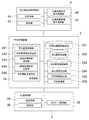
図1は、本実施形態に係る予約管理装置を含むネットワークシステム(予約管理システム)のハードウェアの要部構成を表すブロック図である。
図1に表したネットワークシステムは、主として、予約管理装置2と、複数の利用者端末と、複数の施設端末と、を備える。なお、図1においては、1つの利用者端末3と、第1施設の施設端末4と、第2施設の施設端末5と、が表されている。施設端末の数は、2つには限定されず、3つ以上であってもよい。
FIG. 1 is a block diagram showing a main configuration of hardware of a network system (reservation management system) including a reservation management apparatus according to the present embodiment.
The network system shown in FIG. 1 mainly includes a
予約管理装置2は、コンピュータ(サーバコンピュータ)21と、コンピュータ21に接続された外部記憶装置22と、を有する。外部記憶装置22としては、例えばハードディスクドライブ(HDD:Hard Disk Drive)などが挙げられる。外部記憶装置22は、コンピュータ21によって実行されるプログラム23(予約管理プログラム)を格納する。本実施形態のプログラム23は、本発明の「予約管理プログラム」に相当する。
The
利用者端末3は、利用者によって使用される例えばスマートフォンやタブレットコンピュータなどの携帯型の端末装置である。利用者端末3は、例えば利用者の指の接触等を検出可能なタッチパネルを含むディスプレイを有していてもよい。また、利用者端末3は、利用者の現在位置(利用者端末3の存在位置)を検知する機能を有していてもよい。なお、利用者の現在位置は、例えばGPS(Global Positioning System)によって検知可能とされている。利用者端末3は、コンピュータ31と、コンピュータ31に接続された記憶装置32と、を有する。記憶装置32は、コンピュータ31によって実行されるプログラム33を格納する。
The
第1施設の施設端末4は、例えば飲食店等の各種施設に設置される端末装置である。施設端末4は、第1施設において案内の順番待ちをしている施設利用者を登録したり管理したりする機能を有する。施設端末4は、コンピュータ41と、コンピュータ41に接続された記憶装置42と、を有する。記憶装置42は、コンピュータ41によって実行されるプログラム43を格納する。
The
第2施設の施設端末5は、第1施設の施設端末4と同様の端末装置である。すなわち、第2施設の施設端末5は、第2施設において案内の順番待ちをしている施設利用者を登録したり管理したりする機能を有する。施設端末5は、コンピュータ51と、コンピュータ51に接続された記憶装置52と、を有する。記憶装置52は、コンピュータ51によって実行されるプログラム53を格納する。
The
図1に表したように、予約管理装置2、利用者端末3、第1施設の施設端末4および第2施設の施設端末5は、例えばインターネットなどのネットワーク6を介して互いに通信可能に接続されている。
As shown in FIG. 1, the
予約管理装置2のプログラム23は、コンピュータ読み取り可能な記憶媒体に予め格納され頒布されてもよく、あるいはネットワーク6を介して予約管理装置2にダウンロードされてもよい。利用者端末3のプログラム33は、コンピュータ読み取り可能な記憶媒体に予め格納され頒布されてもよく、あるいはネットワーク6を介して利用者端末3にダウンロードされてもよい。施設端末4のプログラム43は、コンピュータ読み取り可能な記憶媒体に予め格納され頒布されてもよく、あるいはネットワーク6を介して施設端末4にダウンロードされてもよい。施設端末5のプログラム53は、コンピュータ読み取り可能な記憶媒体に予め格納され頒布されてもよく、あるいはネットワーク6を介して施設端末5にダウンロードされてもよい。
The
図2は、本実施形態の予約管理システムの機能構成を表すブロック図である。
図1に関して前述したように、第2施設の施設端末5の構成要素は、第1施設の施設端末4の構成要素と同様である。そのため、説明の便宜上、施設端末の構成の説明では、第1施設の施設端末4を例に挙げる。また、以下の説明では、第2施設が、第1施設の近隣店舗として第1施設により予め指定された場合を例に挙げる。但し、第1施設により予め指定される近隣店舗は、1つの施設には限定されず、複数の施設であってもよい。
FIG. 2 is a block diagram showing a functional configuration of the reservation management system of the present embodiment.
As described above with reference to FIG. 1, the components of the
図2に表したように、予約管理装置2は、送受信部24と、近隣店舗情報格納部251と、待ち組数格納部252と、利用者情報格納部253と、待ち時間算出部254と、所要時間算出部255と、予約管理部256と、を有する。送受信部24は、待ち組数受信部241と、利用者情報送受信部242と、近隣店舗情報送信部243と、近隣店舗状況送信部244と、予約情報送受信部245と、を有する。
As shown in FIG. 2, the
本実施形態において、近隣店舗情報格納部251と、待ち組数格納部252および利用者情報格納部253は、例えば外部記憶装置22に格納されている。また、送受信部24、待ち時間算出部254、所要時間算出部255および予約管理部256は、外部記憶装置22に格納されているプログラム23をコンピュータ21が実行することにより実現される。なお、送受信部24、待ち時間算出部254、所要時間算出部255および予約管理部256は、ハードウェアによって実現されてもよく、ハードウェアとソフトウェアとの組み合わせによって実現されてもよい。
In the present embodiment, the neighborhood store
送受信部24は、各種情報を利用者端末3から受信したり利用者端末3に送信したりする。また、送受信部24は、各種情報を施設端末4および施設端末5から受信したり施設端末4および施設端末5に送信したりする。
The transmission /
具体的には、待ち組数受信部241は、第1施設および第2施設のそれぞれにおいて順番待ちをしている利用者の待ち組数を施設端末4および施設端末5のそれぞれから定期的に受信する。待ち組数受信部241により定期的に受信された待ち組数は、待ち組数格納部252に送信され格納(上書き)される。
Specifically, the waiting group
利用者情報送受信部242は、各施設を利用する利用者に関する情報を利用者端末3および施設端末4の少なくともいずれかから受信する。利用者情報としては、例えば、予め登録された利用者を識別するための利用者ID、利用者の名前(利用者名)、利用者端末3の電話番号および利用者端末3のメールアドレスなどが挙げられる。
The user information transmission /
近隣店舗情報送信部243は、第1施設の近隣店舗に関する施設情報(近隣店舗情報)を利用者端末3および施設端末4の少なくともいずれかに送信する。近隣店舗情報としては、近隣店舗の名称、近隣店舗の住所(所在位置)、および近隣店舗のウェブページのURL(Uniform Resource Locator)が埋め込まれたQRコード(登録商標)などが挙げられる。第1施設の近隣店舗は、第1施設により予め指定されている。本実施形態の説明では、第1施設により予め指定された近隣店舗が、第2施設である場合を例に挙げる。
The neighboring store
近隣店舗状況送信部244は、第1施設の近隣店舗(本実施形態では第2施設)の混雑状況(近隣店舗状況)を利用者端末3および施設端末4の少なくともいずれかに送信する。すなわち、近隣店舗状況送信部244は、第1施設により近隣店舗として予め指定された第2施設の混雑状況を、第1施設の施設端末4に送信する。近隣店舗状況としては、各施設の待ち組数および待ち時間などが挙げられる。待ち時間の詳細については、後述する。
The neighboring store
予約情報送受信部245は、各施設に対する予約を行うための予約情報を施設端末4から受信したり、予約情報が入力された施設端末4以外の施設端末5に送信したりする。また、予約情報送受信部245は、各施設に対する予約を行うための予約情報を利用者端末3から受信したり施設端末4および施設端末5に送信したりする。予約情報としては、予約受付(順番待ち受付)の人数や、席カテゴリなどが挙げられる。席カテゴリとしては、例えば、禁煙席および喫煙席や、カウンタ席、テーブル席および座席などの種類が挙げられる。
The reservation information transmission /
近隣店舗情報格納部251は、近隣店舗情報を格納する。近隣店舗情報の例は、前述した通りである。
待ち組数格納部252は、待ち組数受信部241により定期的に受信された待ち組数を格納する。
利用者情報格納部253は、利用者情報送受信部242により受信された利用者情報を格納する。利用者情報の例は、前述した通りである。
The neighborhood store
The waiting group
The user
待ち時間算出部254は、待ち組数格納部252を参照し、待ち組数格納部252に格納された待ち組数に基づいて利用者を各施設に案内できるまでの待ち時間を算出する。例えば、予約管理装置2においては、施設毎に、各曜日、各時間帯(例えば1時間単位)における利用者の1組(1人)あたりの待ち時間が予め設定(保持)されている。例えば、1組あたりの待ち時間は、各施設の規模や利用者の回転率等に応じて設定されている。この場合には、待ち時間算出部254は、1組あたりの待ち時間および待ち組数を乗算することによって待ち時間を算出することができる。
The waiting
なお、待ち時間の算出方法は、これだけには限定されない。待ち時間算出部254は、他の方法によって待ち時間を算出してもよい。また、前述した1組あたりの待ち時間としては、過去(例えば1年前や2年前の同日または同曜日)の実際の待ち時間等が利用されてもよい。この場合には、過去の実際の待ち時間等が予約管理装置2において蓄積されていればよい。
Note that the method for calculating the waiting time is not limited to this. The waiting
所要時間算出部255は、近隣店舗情報格納部251に格納された各施設の住所(所在位置)に基づいて、各施設間の所要時間を算出する。例えば、所要時間算出部255は、第1施設から第2施設までの経路を算出し、経路の距離および経路における自動車の制限速度等を用いて算出することができる。あるいは、所要時間算出部255は、第1施設から第2施設までの経路を算出し、経路の距離および利用者の徒歩速度等を用いて算出することができる。所要時間の算出に必要な各施設間の経路は、例えば地図情報等が予約管理装置2内に格納されている場合には、予約管理装置2内で算出されてもよい。あるいは、所要時間算出部255は、予約管理装置2以外の端末装置(例えば利用者端末3や施設端末4など)の所要時間算出部により算出された所要時間を利用してもよい。
The required
予約管理部256は、利用者情報送受信部242により受信された利用者情報を取得したり、予約情報送受信部245により受信された予約情報を取得したりする。また、予約管理部256は、利用者情報送受信部242を介して利用者情報を施設端末4に送信したり、予約情報送受信部245を介して予約情報を施設端末4に送信したりする。
The
利用者端末3は、送受信部34と、表示部35と、QRコード読取部36と、を有する。送受信部34は、各種情報を予約管理装置2から受信したり予約管理装置2に送信したりする。表示部35は、例えば利用者の指の接触等を検出可能なタッチパネルを含むディスプレイである。利用者は、利用者端末3の表示部35を操作することにより利用者情報および予約情報を入力することができる。なお、利用者端末3は、利用者の現在位置(利用者端末3の存在位置)を例えばGPS等により検知する現在位置検知部を有していてもよい。QRコード読取部36は、例えば第1施設の施設端末4に表示されたQRコード(登録商標)を読み取る。
The
施設端末4は、送受信部44と、表示部45と、近隣店舗状況表示処理部46と、近隣店舗情報表示処理部47と、を有する。送受信部44は、各種情報を予約管理装置2から受信したり予約管理装置2に送信したりする。表示部45は、例えば利用者の指の接触等を検出可能なタッチパネルを含むディスプレイである。利用者は、施設端末4の表示部45を操作することにより利用者情報および予約情報を入力することができる。
The
近隣店舗状況表示処理部46は、送受信部44により受信された近隣店舗状況を表示部45に表示する処理を実行する。例えば、近隣店舗状況表示処理部46は、第1施設の近隣店舗(本実施形態では第2施設)の混雑状況(近隣店舗状況)を第1施設の施設端末4の表示部45に表示する処理を実行する。
The neighboring store status
近隣店舗情報表示処理部47は、送受信部44により受信された近隣店舗情報を表示部45に表示する処理を実行する。例えば、第1施設の施設端末4の表示部45に表示された近隣店舗状況に対して利用者が第2施設を選択すると、近隣店舗情報表示処理部47は、送受信部44により受信された第2施設に関する施設情報(近隣店舗情報)を第1施設の施設端末4の表示部45に表示する処理を実行する。
The neighboring store information
次に、本実施形態に係る予約管理装置の処理手順を、図面を参照して説明する。
図3は、第1施設の施設端末に表示された画面の一例を例示する図である。
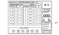
図4は、第1施設の施設端末に表示された近隣店舗状況の一例を例示する図である。
図5は、本実施形態に係る予約管理装置の第1処理手順を表すシーケンスチャートである。
本実施形態に係る予約管理装置2の処理手順の説明では、第1施設の施設端末4の表示部45に表示された近隣店舗状況に対して利用者が第2施設を選択する場合を例に挙げる。
Next, a processing procedure of the reservation management apparatus according to the present embodiment will be described with reference to the drawings.
FIG. 3 is a diagram illustrating an example of a screen displayed on the facility terminal of the first facility.
FIG. 4 is a diagram illustrating an example of the neighborhood store status displayed on the facility terminal of the first facility.
FIG. 5 is a sequence chart showing a first processing procedure of the reservation management apparatus according to the present embodiment.
In the description of the processing procedure of the
図3に表したように、本実施形態に係る予約管理装置2は、第1施設に設置された施設端末4の表示部45に、第1施設により予め指定された近隣店舗(図3では、第2施設、第3施設および第4施設)の混雑状況を示す近隣店舗状況を表示させることができる。図3に表した例では、近隣店舗状況は、施設端末4の表示部45の領域A1に表示され、第2施設、第3施設および第4施設の混雑状況を含んでいる。このように、第1施設により予め指定される近隣店舗は、1つの施設には限定されず、複数の施設であってもよい。また、近隣店舗状況が表示される領域は、図3に表した領域A1には限定されない。図4に表した例では、近隣店舗における待ち時間が、近隣店舗状況として施設端末4の表示部45に表示されている。なお、施設端末4の表示部45に表示される近隣店舗状況は、近隣店舗における待ち時間および待ち組数を含んでいてもよい。また、図4に表した例では、近隣店舗の名称および住所が、近隣店舗情報として近隣店舗状況とともに施設端末4の表示部45に表示されている。
As shown in FIG. 3, the
本実施形態に係る予約管理装置の第1処理手順を具体的に説明すると、図5に表したように、まず、第1施設の施設端末4は、第1施設において順番待ちをしている利用者の待ち組数を送受信部44を介して予約管理装置2に定期的に送信する(ステップS11)。また、第2施設の施設端末5は、第2施設において順番待ちをしている利用者の待ち組数を施設端末5の送受信部を介して予約管理装置2に定期的に送信する(ステップS12)。
The first processing procedure of the reservation management apparatus according to the present embodiment will be described in detail. As shown in FIG. 5, first, the
続いて、予約管理装置2の待ち組数受信部241は、各施設における待ち組数を受信する(ステップS13)。待ち組数受信部241により受信された待ち組数は、待ち組数格納部252に送信され格納される。続いて、待ち時間算出部254は、待ち組数格納部252を参照し、待ち組数格納部252に格納された待ち組数に基づいて、利用者を各施設に案内できるまでの待ち時間を算出する(ステップS14)。待ち時間算出部254が待ち時間を算出する方法の例は、図2に関して前述した通りである。続いて、近隣店舗状況送信部244は、第2施設における待ち組数および待ち時間を近隣店舗状況として第1施設の施設端末4からの要求に応じて第1施設の施設端末4に送信する(ステップS15)。なお、図3および図4に表したように、第1施設により予め指定された近隣店舗が第2施設、第3施設および第4施設である場合には、近隣店舗状況送信部244は、第2施設、第3施設および第4施設のそれぞれにおける待ち組数および待ち時間を近隣店舗状況として第1施設の施設端末4からの要求に応じて第1施設の施設端末4に送信する。
Subsequently, the waiting group
続いて、施設端末4の送受信部44は、第2施設の混雑状況(近隣店舗状況)を受信する(ステップS16)。続いて、近隣店舗状況表示処理部46は、送受信部44により受信された近隣店舗状況を施設端末4の表示部45に表示する処理を実行する(ステップS17)。続いて、送受信部44は、施設端末4に表示された近隣店舗状況に対する利用者の操作に応じて利用者により選択された第2施設の選択情報を予約管理装置2に送信する(ステップS18)。
Subsequently, the transmission /
続いて、予約管理装置2の送受信部24は、利用者により選択された第2施設の選択情報を受信する(ステップS19)。続いて、近隣店舗情報送信部243は、近隣店舗情報格納部251を参照し、近隣店舗情報格納部251に格納された第2施設に関する近隣店舗情報を第1施設の施設端末4からの要求応じて第1施設の施設端末4に送信する(ステップS21)。
Subsequently, the transmission /
続いて、施設端末4の送受信部44は、予約管理装置2の近隣店舗情報送信部243から送信された第2施設に関する近隣店舗情報を受信する(ステップS22)。続いて、近隣店舗情報表示処理部47は、送受信部44により受信された第2施設に関する近隣店舗情報を施設端末4の表示部45に表示する処理を実行する(ステップS23)。そして、施設端末4の送受信部44は、第2施設に関する近隣店舗情報を利用者端末3に送信する(ステップS24)。なお、例えばQRコード(登録商標)などのように、利用者端末3が第2施設に関する近隣店舗情報を施設端末4の表示部45から取得できる場合には、施設端末4の送受信部44は、第2施設に関する近隣店舗情報を必ずしも利用者端末3に送信しなくともよい。
Subsequently, the transmitting / receiving
続いて、利用者端末3は、施設端末4の表示部45に表示された第2施設に関する近隣店舗情報を取得する(ステップS25)。例えば、第2施設のウェブページのURL(Uniform Resource Locator)が埋め込まれたQRコード(登録商標)が、第2施設に関する近隣店舗情報として施設端末4の表示部45に表示される。この場合には、利用者端末3は、施設端末4の表示部45に表示された第2施設に関するQRコード(登録商標)をQRコード読取部36により読み取り、第2施設のウェブページに接続する。
Subsequently, the
続いて、利用者は、利用者端末3の表示部35を操作することにより第2施設のウェブページにおいて利用者情報および予約情報を入力する。このときに利用者が入力する利用者情報としては、例えば、予め登録された利用者を識別するための利用者ID、利用者の名前(利用者名)、利用者端末3の電話番号および利用者端末3のメールアドレスなどが挙げられる。また、このときに利用者が入力する予約情報としては、予約受付(順番待ち受付)の人数および席カテゴリなどが挙げられる。席カテゴリとしては、例えば、禁煙席および喫煙席や、カウンタ席、テーブル席や、座席などの種類が挙げられる。続いて、利用者端末3の送受信部34は、第2施設のウェブページにおいて利用者により入力された利用者情報および予約情報を予約管理装置2に送信する(ステップS26)。
Subsequently, the user operates the
続いて、予約管理部256は、利用者情報送受信部242を介して利用者端末3の送受信部34から送信された利用者情報と、予約情報送受信部245を介して利用者端末3の送受信部34から送信された予約情報と、を受信する(ステップS27)。続いて、予約管理部256は、利用者情報送受信部242を介して第2施設の施設端末5に利用者情報を送信し、予約情報送受信部245を介して第2施設の施設端末5に予約情報を送信する(ステップS28)。
Subsequently, the
第2施設の施設端末5は、利用者情報送受信部242を介して予約管理部256から送信された利用者情報と、予約情報送受信部245を介して予約管理部256から送信された予約情報と、を受信する(ステップS29)。これにより、第1施設により近隣店舗として予め指定された第2施設に対する利用者の予約受付(順番待ち受付)が完了する。
The
本実施形態に係る予約管理装置2の第1処理手順によれば、利用者は、予約管理装置2と通信可能に接続された施設端末が導入された複数の施設のうちで第1施設により近隣店舗として予め指定された第2施設の混雑状況(近隣店舗状況)を、第1施設に設置された施設端末4において確認することができる。つまり、利用者は、利用者自身が訪れた第1施設の待ち組数や待ち時間だけではなく、第1施設により近隣店舗として予め指定された第2施設の待ち組数や待ち時間(混雑状況)を近隣店舗状況として第1施設に設置された施設端末4において確認することができる。そのため、利用者が訪れた第1施設が混雑している場合であっても、予約管理装置2は、第1施設を訪れた利用者に対して第2施設の利用を促すことができる。これにより、同じ系列の複数の施設を運営するオーナ企業は、利用者の囲い込みをより確実に行い、オーナ企業が運営する複数の施設の利用者数を増加させることができる。
According to the first processing procedure of the
また、近隣店舗情報表示処理部47は、送受信部44により受信された第2施設に関する近隣店舗情報を施設端末4の表示部45に表示する処理を実行する。そして、利用者端末3は、施設端末4の表示部45に表示された第2施設に関する近隣店舗情報を取得できる。例えば、利用者端末3は、施設端末4の表示部45に表示された第2施設に関するQRコード(登録商標)をQRコード読取部36により読み取り、第2施設のウェブページに接続することができる。これにより、予約管理装置2は、第1施設を訪れた利用者に対して第2施設の利用を促すことができるとともに、第2施設のウェブページを利用して予約受付(順番待ち受付)を促すことができる。あるいは、利用者は、第1施設に設置された施設端末4に表示された近隣店舗状況において選択した第2施設の名称や住所などの施設情報を、第1施設に設置された施設端末4から取得できる。そのため、利用者は、第2施設の所在位置を把握し、第1施設から第2施設に向かって移動することができる。これにより、同じ系列の複数の施設を運営するオーナ企業は、利用者の囲い込みをより確実に行い、オーナ企業が運営する複数の施設の利用者数を増加させることができる。
In addition, the nearby store information
図6は、本実施形態に係る予約管理装置の第2処理手順を表すシーケンスチャートである。
まず、図6に表したステップS11〜ステップS23の処理は、図5に関して前述したステップS11〜ステップS23の処理と同じである。
FIG. 6 is a sequence chart showing a second processing procedure of the reservation management apparatus according to the present embodiment.
First, the processes in steps S11 to S23 shown in FIG. 6 are the same as the processes in steps S11 to S23 described above with reference to FIG.
本実施形態に係る予約管理装置2の第2処理手順では、利用者は、ステップS23において第1施設の施設端末4の表示部45に表示された第2施設に関する近隣店舗情報に基づいて施設端末4の表示部45を操作することにより、利用者情報および予約情報を入力する。このときに利用者が入力する利用者情報および予約情報のそれぞれの例は、図5に関して前述した通りである。
In the second processing procedure of the
続いて、施設端末4の送受信部44は、第1施設の施設端末4の表示部45に表示された第2施設に関する近隣店舗情報において利用者により入力された利用者情報および予約情報を予約管理装置2に送信する(ステップS31)。続いて、予約管理部256は、利用者情報送受信部242を介して施設端末4の送受信部44から送信された利用者情報と、予約情報送受信部245を介して施設端末4の送受信部44から送信された予約情報と、を受信する(ステップS32)。続いて、予約管理部256は、利用者情報送受信部242を介して第2施設の施設端末5に利用者情報を送信し、予約情報送受信部245を介して第2施設の施設端末5に予約情報を送信する(ステップS33)。
Subsequently, the transmission /
第2施設の施設端末5は、利用者情報送受信部242を介して予約管理部256から送信された利用者情報と、予約情報送受信部245を介して予約管理部256から送信された予約情報と、を受信する(ステップS34)。これにより、第1施設により近隣店舗として予め指定された第2施設に対する利用者の予約受付(順番待ち受付)が完了する。
The
このとき、予約管理部256は、待ち時間算出部254により算出された第2施設における待ち時間と、所要時間算出部255により算出された第1施設から第2施設までの所要時間と、を参照し、第2施設に対する利用者の予約受付(順番待ち受付)を行ってもよい。すなわち、予約管理部256は、待ち時間算出部254により算出された第2施設における待ち時間と、所要時間算出部255により算出された第1施設から第2施設までの所要時間と、を比較し、所要時間が待ち時間以下となる順番で利用者の予約受付(順番待ち受付)を行う。これによれば、待ち時間が経過し利用者を第2施設に案内する案内時間になっても、利用者が第2施設に到着していないという事態を回避することができる。
At this time, the
本実施形態に係る予約管理装置2の第2処理手順によれば、第1施設を訪れた利用者は、第1施設に設置された施設端末4を利用して、第2施設に対する予約受付(順番待ち受付)を行うことができる。つまり、利用者は、利用者端末3を利用しなくとも、第1施設に設置された施設端末4を用いて、第2施設に対する予約受付を行うことができる。これにより、同じ系列の複数の施設を運営するオーナ企業は、利用者の囲い込みをより確実に行い、オーナ企業が運営する複数の施設の利用者数を増加させることができる。
According to the second processing procedure of the
以上、本発明の実施形態について説明した。しかし、本発明は、上記実施形態に限定されず、特許請求の範囲を逸脱しない範囲で種々の変更を行うことができる。上記実施形態の構成は、その一部を省略したり、上記とは異なるように任意に組み合わせたりすることができる。 The embodiment of the present invention has been described above. However, the present invention is not limited to the above-described embodiment, and various modifications can be made without departing from the scope of the claims. A part of the configuration of the above embodiment can be omitted, or can be arbitrarily combined so as to be different from the above.
2・・・予約管理装置、 3・・・利用者端末、 4、5・・・施設端末、 6・・・ネットワーク、 21・・・コンピュータ、 22・・・外部記憶装置、 23・・・プログラム、 24・・・送受信部、 31・・・コンピュータ、 32・・・記憶装置、 33・・・プログラム、 34・・・送受信部、 35・・・表示部、 36・・・コード読取部、 41・・・コンピュータ、 42・・・記憶装置、 43・・・プログラム、 44・・・送受信部、 45・・・表示部、 46・・・近隣店舗状況表示処理部、 47・・・近隣店舗情報表示処理部、 51・・・コンピュータ、 52・・・記憶装置、 53・・・プログラム、 241・・・待ち組数受信部、 242・・・利用者情報送受信部、 243・・・近隣店舗情報送信部、 244・・・近隣店舗状況送信部、 245・・・予約情報送受信部、 251・・・近隣店舗情報格納部、 252・・・待ち組数格納部、 253・・・利用者情報格納部、 254・・・時間算出部、 255・・・所要時間算出部、 256・・・予約管理部
2 ... Reservation management device, 3 ... User terminal, 4, 5 ... Facility terminal, 6 ... Network, 21 ... Computer, 22 ... External storage device, 23 ... Program , 24 ... Transmission / reception unit, 31 ... Computer, 32 ... Storage device, 33 ... Program, 34 ... Transmission / reception unit, 35 ... Display unit, 36 ... Code reading unit, 41・ ・ ・ Computer, 42 ... Storage device, 43 ... Program, 44 ... Transmission / reception unit, 45 ... Display unit, 46 ... Neighborhood store status display processing unit, 47 ... Nearby store information Display processing unit, 51 ... Computer, 52 ... Storage device, 53 ... Program, 241 ... Waiting group number receiving unit, 242 ... User information transmission / reception unit, 243 ... Neighborhood store information Transmitter, 244 ... nearby Store status transmission unit, 245 ... reservation information transmission / reception unit, 251 ... neighborhood store information storage unit, 252 ... waiting group number storage unit, 253 ... user information storage unit, 254 ... time calculation Part, 255... Required time calculation part, 256... Reservation management part
Claims (4)
前記複数の施設のうちで第1施設により近隣店舗として予め指定された第2施設の混雑状況を示す近隣店舗状況を前記第1施設に設置された前記施設端末からの要求に応じて送信し、前記第1施設に設置された前記施設端末に前記近隣店舗状況を表示させるとともに、前記第1施設に設置された前記施設端末に対する前記利用者の操作に応じて前記利用者により入力され前記第2施設に対する予約を行うための予約情報と、前記第1施設に設置された前記施設端末に対する前記利用者の操作に応じて前記利用者により入力され前記第2施設を選択した前記利用者の情報を示す利用者情報と、を受信し、前記第2施設における待ち時間と、前記第1施設から前記第2施設までの所要時間と、を比較し、複数の前記待ち時間のうちで前記所要時間よりも短い前記待ち時間が存在する場合であっても前記所要時間が前記待ち時間以下となる順番で前記利用者の前記順番待ち受付を行い、前記第2施設に設置された前記施設端末に前記利用者情報および前記予約情報を送信することを特徴とする予約管理装置。 A reservation management unit that manages a waiting in communicatively connected to a facility terminal installed in each of the user terminal and a plurality of facilities are used the facility by the user,
In response to a request from the facility terminal installed in the first facility, the neighboring store status indicating the congestion status of the second facility designated in advance as a neighboring store by the first facility among the plurality of facilities, The neighboring store status is displayed on the facility terminal installed in the first facility, and is input by the user according to an operation of the user on the facility terminal installed in the first facility. Reservation information for making a reservation for the facility, and information on the user who has selected the second facility input by the user in response to the user's operation on the facility terminal installed in the first facility The waiting time in the second facility and the required time from the first facility to the second facility, and the required time among a plurality of the waiting times. Even when the waiting time is as short as possible, the user waits for the turn in the order in which the required time is equal to or shorter than the waiting time, and the facility terminal installed in the second facility receives the waiting time. A reservation management apparatus, wherein user information and the reservation information are transmitted .
前記複数の施設のうちで第1施設により近隣店舗として予め指定された第2施設の混雑状況を示す近隣店舗状況を前記第1施設に設置された前記施設端末からの要求に応じて送信する第1ステップと、
前記第1施設に設置された前記施設端末に前記近隣店舗状況を表示させる第2ステップと、
前記第1施設に設置された前記施設端末に対する前記利用者の操作に応じて前記利用者により入力され前記第2施設に対する予約を行うための予約情報、および前記第1施設に設置された前記施設端末に対する前記利用者の操作に応じて前記利用者により入力され前記第2施設を選択した前記利用者の情報を示す利用者情報と、を受信する第3ステップと、
前記第2施設における待ち時間と、前記第1施設から前記第2施設までの所要時間と、を比較し、複数の前記待ち時間のうちで前記所要時間よりも短い前記待ち時間が存在する場合であっても前記所要時間が前記待ち時間以下となる順番で前記利用者の前記順番待ち受付を行う第4ステップと、
前記第2施設に設置された前記施設端末に前記利用者情報および前記予約情報を送信する第5ステップと、
を備えたことを特徴とする予約管理方法。 A user terminal and reservations management method facility terminal and to manage the waiting in communicatively coupled to the facility reservation management unit executes installed in each of the plurality of facilities used by the user,
A second store is sent in response to a request from the facility terminal installed at the first facility, indicating the congestion status of the second facility preliminarily designated as a nearby store by the first facility among the plurality of facilities. One step,
A second step of displaying the neighboring store status on the facility terminal installed in the first facility;
Reservation information for making a reservation for the second facility inputted by the user in response to the user's operation on the facility terminal installed in the first facility, and the facility installed in the first facility A third step of receiving user information that is input by the user in response to an operation of the user on the terminal and that indicates information of the user who has selected the second facility;
When the waiting time in the second facility is compared with the required time from the first facility to the second facility, and the waiting time shorter than the required time exists among the plurality of waiting times. A fourth step of accepting the waiting of the user in the order in which the required time is less than or equal to the waiting time,
A fifth step of transmitting the user information and the reservation information to the facility terminal installed in the second facility;
A reservation management method characterized by comprising:
前記コンピュータに、
前記複数の施設のうちで第1施設により近隣店舗として予め指定された第2施設の混雑状況を示す近隣店舗状況を前記第1施設に設置された前記施設端末からの要求に応じて送信する第1ステップと、
前記第1施設に設置された前記施設端末に前記近隣店舗状況を表示させる第2ステップと、
前記第1施設に設置された前記施設端末に対する前記利用者の操作に応じて前記利用者により入力され前記第2施設に対する予約を行うための予約情報、および前記第1施設に設置された前記施設端末に対する前記利用者の操作に応じて前記利用者により入力され前記第2施設を選択した前記利用者の情報を示す利用者情報と、を受信する第3ステップと、
前記第2施設における待ち時間と、前記第1施設から前記第2施設までの所要時間と、を比較し、複数の前記待ち時間のうちで前記所要時間よりも短い前記待ち時間が存在する場合であっても前記所要時間が前記待ち時間以下となる順番で前記利用者の前記順番待ち受付を行う第4ステップと、
前記第2施設に設置された前記施設端末に前記利用者情報および前記予約情報を送信する第5ステップと、
を実行させることを特徴とする予約管理プログラム。 A Book management program executed is communicatively connected to a facility terminal installed in each of the user terminal and a plurality of facilities used by the user by the computer of the reservation management unit that manages the waiting in the facility And
In the computer,
A second store is sent in response to a request from the facility terminal installed at the first facility, indicating the congestion status of the second facility preliminarily designated as a nearby store by the first facility among the plurality of facilities. One step,
A second step of displaying the neighboring store status on the facility terminal installed in the first facility;
Reservation information for making a reservation for the second facility inputted by the user in response to the user's operation on the facility terminal installed in the first facility, and the facility installed in the first facility A third step of receiving user information that is input by the user in response to an operation of the user on the terminal and that indicates information of the user who has selected the second facility;
When the waiting time in the second facility is compared with the required time from the first facility to the second facility, and the waiting time shorter than the required time exists among the plurality of waiting times. A fourth step of accepting the waiting of the user in the order in which the required time is less than or equal to the waiting time,
A fifth step of transmitting the user information and the reservation information to the facility terminal installed in the second facility;
A reservation management program characterized in that
Priority Applications (1)
| Application Number | Priority Date | Filing Date | Title |
|---|---|---|---|
| JP2017165906A JP6442012B1 (en) | 2017-08-30 | 2017-08-30 | Reservation management apparatus, reservation management method, and reservation management program |
Applications Claiming Priority (1)
| Application Number | Priority Date | Filing Date | Title |
|---|---|---|---|
| JP2017165906A JP6442012B1 (en) | 2017-08-30 | 2017-08-30 | Reservation management apparatus, reservation management method, and reservation management program |
Publications (2)
| Publication Number | Publication Date |
|---|---|
| JP6442012B1 true JP6442012B1 (en) | 2018-12-19 |
| JP2019045977A JP2019045977A (en) | 2019-03-22 |
Family
ID=64668510
Family Applications (1)
| Application Number | Title | Priority Date | Filing Date |
|---|---|---|---|
| JP2017165906A Active JP6442012B1 (en) | 2017-08-30 | 2017-08-30 | Reservation management apparatus, reservation management method, and reservation management program |
Country Status (1)
| Country | Link |
|---|---|
| JP (1) | JP6442012B1 (en) |
Cited By (1)
| Publication number | Priority date | Publication date | Assignee | Title |
|---|---|---|---|---|
| JP2020087303A (en) * | 2018-11-30 | 2020-06-04 | 株式会社Epark | Reservation management device, reservation management method and reservation management program |
Citations (5)
| Publication number | Priority date | Publication date | Assignee | Title |
|---|---|---|---|---|
| JPH08180113A (en) * | 1994-12-21 | 1996-07-12 | Nitsuko Corp | Reservation system of chain restaurant |
| JP2005050002A (en) * | 2003-07-30 | 2005-02-24 | Inst:Kk | Reservation management system and reservation management method |
| US20050259653A1 (en) * | 2003-07-28 | 2005-11-24 | Q-Nomy Inc. | System architecture and method for customer flow management |
| JP2014026360A (en) * | 2012-07-25 | 2014-02-06 | Oki Electric Ind Co Ltd | Reception control device, reception control system, reception control method, and program |
| JP5883892B2 (en) * | 2014-01-24 | 2016-03-15 | 株式会社Epark | Reservation management apparatus, reservation management method and program |
-
2017
- 2017-08-30 JP JP2017165906A patent/JP6442012B1/en active Active
Patent Citations (5)
| Publication number | Priority date | Publication date | Assignee | Title |
|---|---|---|---|---|
| JPH08180113A (en) * | 1994-12-21 | 1996-07-12 | Nitsuko Corp | Reservation system of chain restaurant |
| US20050259653A1 (en) * | 2003-07-28 | 2005-11-24 | Q-Nomy Inc. | System architecture and method for customer flow management |
| JP2005050002A (en) * | 2003-07-30 | 2005-02-24 | Inst:Kk | Reservation management system and reservation management method |
| JP2014026360A (en) * | 2012-07-25 | 2014-02-06 | Oki Electric Ind Co Ltd | Reception control device, reception control system, reception control method, and program |
| JP5883892B2 (en) * | 2014-01-24 | 2016-03-15 | 株式会社Epark | Reservation management apparatus, reservation management method and program |
Cited By (1)
| Publication number | Priority date | Publication date | Assignee | Title |
|---|---|---|---|---|
| JP2020087303A (en) * | 2018-11-30 | 2020-06-04 | 株式会社Epark | Reservation management device, reservation management method and reservation management program |
Also Published As
| Publication number | Publication date |
|---|---|
| JP2019045977A (en) | 2019-03-22 |
Similar Documents
| Publication | Publication Date | Title |
|---|---|---|
| US10302443B2 (en) | Navigation server and program | |
| US20230401495A1 (en) | Service management method and system | |
| JP7285583B2 (en) | Information processing system | |
| EP3012797A1 (en) | Electronic device and method of operating content receiver recommendation service | |
| KR20190068603A (en) | Service Provider Operational Decision Techniques with Range-Dependent Transmissions | |
| US20140195968A1 (en) | Inferring and acting on user intent | |
| JP2012164125A (en) | Reservation management system | |
| JP2015138491A (en) | Reservation management device, reservation management method and program | |
| AU2019200940A1 (en) | Ticket and conveyance management systems | |
| JP6442012B1 (en) | Reservation management apparatus, reservation management method, and reservation management program | |
| JP2011014048A (en) | Apparatus and method for processing information, and program | |
| US20130013451A1 (en) | Optimum Route Generation Based on Common Purchase Plan of Different Travelers | |
| JP5956120B2 (en) | Information processing system, information processing apparatus, information processing program, and information processing method | |
| JP6539403B1 (en) | Reservation management apparatus, reservation management method and reservation management program | |
| US20180114375A1 (en) | Method, device and system for automatic time recordal | |
| US20200082430A1 (en) | Terminal device, display method, and recording medium | |
| JP6598968B1 (en) | Reservation management apparatus, reservation management method, and reservation management program | |
| JP2016099820A (en) | Information processing system, information processing terminal, and program | |
| JP5066956B2 (en) | Search support method, mobile terminal for search, server device, search support system, and computer program | |
| JP6651043B1 (en) | Reservation management device, reservation management method and reservation management program | |
| WO2012143849A1 (en) | Creating a database entry | |
| KR20190004449A (en) | Method for providing automatic reservation change service based on location and apparatus therefor | |
| JP7318131B2 (en) | Service providing system, service providing method, and program | |
| US20160189189A1 (en) | Customer information processing device and customer information processing method | |
| JP2017010211A (en) | Wait time management apparatus, wait time management method, and wait time management system |
Legal Events
| Date | Code | Title | Description |
|---|---|---|---|
| A02 | Decision of refusal |
Free format text: JAPANESE INTERMEDIATE CODE: A02 Effective date: 20180328 |
|
| TRDD | Decision of grant or rejection written | ||
| A01 | Written decision to grant a patent or to grant a registration (utility model) |
Free format text: JAPANESE INTERMEDIATE CODE: A01 Effective date: 20180927 |
|
| A601 | Written request for extension of time |
Free format text: JAPANESE INTERMEDIATE CODE: A601 Effective date: 20181026 |
|
| A61 | First payment of annual fees (during grant procedure) |
Free format text: JAPANESE INTERMEDIATE CODE: A61 Effective date: 20181122 |
|
| R150 | Certificate of patent or registration of utility model |
Ref document number: 6442012 Country of ref document: JP Free format text: JAPANESE INTERMEDIATE CODE: R150 |
|
| R250 | Receipt of annual fees |
Free format text: JAPANESE INTERMEDIATE CODE: R250 |
|
| R250 | Receipt of annual fees |
Free format text: JAPANESE INTERMEDIATE CODE: R250 |
|
| R250 | Receipt of annual fees |
Free format text: JAPANESE INTERMEDIATE CODE: R250 |