JP6441304B2 - Orthodontic appliance and method of operating the same - Google Patents
Orthodontic appliance and method of operating the same Download PDFInfo
- Publication number
- JP6441304B2 JP6441304B2 JP2016502787A JP2016502787A JP6441304B2 JP 6441304 B2 JP6441304 B2 JP 6441304B2 JP 2016502787 A JP2016502787 A JP 2016502787A JP 2016502787 A JP2016502787 A JP 2016502787A JP 6441304 B2 JP6441304 B2 JP 6441304B2
- Authority
- JP
- Japan
- Prior art keywords
- clip
- open
- mesial
- protrusion
- distal
- Prior art date
- Legal status (The legal status is an assumption and is not a legal conclusion. Google has not performed a legal analysis and makes no representation as to the accuracy of the status listed.)
- Expired - Fee Related
Links
Images


Classifications
-
- A—HUMAN NECESSITIES
- A61—MEDICAL OR VETERINARY SCIENCE; HYGIENE
- A61C—DENTISTRY; APPARATUS OR METHODS FOR ORAL OR DENTAL HYGIENE
- A61C7/00—Orthodontics, i.e. obtaining or maintaining the desired position of teeth, e.g. by straightening, evening, regulating, separating, or by correcting malocclusions
- A61C7/12—Brackets; Arch wires; Combinations thereof; Accessories therefor
- A61C7/28—Securing arch wire to bracket
- A61C7/287—Sliding locks
Landscapes
- Health & Medical Sciences (AREA)
- Oral & Maxillofacial Surgery (AREA)
- Dentistry (AREA)
- Epidemiology (AREA)
- Life Sciences & Earth Sciences (AREA)
- Animal Behavior & Ethology (AREA)
- General Health & Medical Sciences (AREA)
- Public Health (AREA)
- Veterinary Medicine (AREA)
- Dental Tools And Instruments Or Auxiliary Dental Instruments (AREA)
Description
本発明は、歯科矯正治療に用いられる接合可能な装具、及びそれに関連する方法に関する。より具体的には、本発明は、接合可能な自己結紮式装具、及びそれに関連する方法に関する。 The present invention relates to connectable appliances used in orthodontic treatment and methods related thereto. More specifically, the present invention relates to a self-ligating brace that can be joined and a method associated therewith.
歯科矯正は、転位歯を正常位置に治療的に移動させることに関与する、歯科学の専門分野である。歯列矯正処置は、咬合機能及び発語の改善、顔の美観向上、並びに歯科衛生維持の容易化を含む多くの利点を患者にもたらし得る。歯の移動に際して、歯科矯正医は矯正装具の使用を処方するのが一般的である。この矯正装具は、患者の歯に機械的に係合させて、穏やかな力を継続的に印加することにより、歯を歯科矯正学的に適正な位置まで漸進的に移動させるものである。治療は多くの場合、症例の複雑性に応じて2〜3年続く。 Orthodontics is a specialized field of dentistry that is involved in therapeutically moving dislocation teeth to a normal position. Orthodontic treatment can provide patients with many benefits including improved occlusal function and speech, improved facial aesthetics, and easier maintenance of dental hygiene. It is common for orthodontists to prescribe the use of orthodontic appliances during tooth movement. This orthodontic appliance mechanically engages the patient's teeth and continuously applies a gentle force to gradually move the teeth to an orthodontic proper position. Treatment often lasts 2-3 years, depending on the complexity of the case.
一般的な様式の治療では、歯科矯正用ブラケットと呼ばれる、スロットを有する小さな装具が使用され、この装具は、歯の表面に接着剤により装着される。弾性アーチ型のワイヤー(「アーチワイヤー」)は一般に、各ブラケットのスロット中に結び付けられている、即ち「結紮されている」。アーチワイヤーの末端部は、一般的には、臼歯用チューブと呼ばれる管形状の装具に捕捉され、患者の臼歯に固着される。アーチワイヤーは当初歪曲されているが、ブラケットに結紮されると、徐々に元の形状に戻っていき、歯の動きを所望される位置に向かって誘導するトラック(track)として機能する。ブラケット、チューブ、及びアーチワイヤーは合わせて、「ブレース」として知られる。 A common mode of treatment uses a small appliance with a slot, called an orthodontic bracket, which is attached to the tooth surface with an adhesive. Elastic arched wires (“archwires”) are typically tied or “ligated” into the slots of each bracket. The distal end of the archwire is typically captured by a tubular appliance called a molar tube and secured to the patient's molar. The archwire is initially distorted, but when it is ligated to the bracket, it gradually returns to its original shape and functions as a track that guides tooth movement toward the desired position. The bracket, tube, and archwire together are known as a “brace”.
従来のブラケットは、ブラケット本体上のクリート状の突起部である、互いに対向する一対以上のタイウィングに補助されてアーチワイヤーに結紮される。アーチワイヤーをアーチワイヤースロット内に定置し、一般的に、小さなエラストマー製の「O」−リング状結紮具、又は代替的に、金属製結紮ワイヤーを、アーチワイヤーの上方、及びアーチワイヤースロットの対向する側面上に位置するタイウィングの逃げ部分の下方に固着させる。この方法では、結紮によって各ブラケットのアーチワイヤースロット内にアーチワイヤーを固定し、これらの本体間の機械的結合を得る。 The conventional bracket is ligated to the archwire with the help of a pair of tie wings facing each other, which are cleat-like protrusions on the bracket body. Place the archwire in the archwire slot, typically a small elastomeric “O” -ring ligature, or alternatively a metal ligature wire, above the archwire and opposite the archwire slot The tie wing is positioned below the side of the tie wing that is positioned on the side surface. In this method, the archwire is secured within the archwire slot of each bracket by ligation to obtain a mechanical connection between these bodies.
しかしながら、結紮の使用によって幾つかの不利益が生じ得る。最初に装着されたとき、例えば、エラストマー製結紮具はアーチワイヤーを非常にきつく固定する傾向があり、結果として、摺動に対する抵抗が比較的高くなる。治療の特定の段階において、例えば、歯を水平にする及び整列するとき、所望せずとも、歯の移動に時間がかかる可能性がある。また、これらの結紮によって弾性が失われて、アーチワイヤーの摺動機構が経時的に変化する傾向もある。そのうえ、各「O」リングをアーチワイヤーの上側及び各ブラケットのタイウィングの下側に伸張させるプロセスは、歯科矯正医にとって煩わしいうえ時間の浪費になる場合もある。最終的に、結紮は、ブラケットのタイウィングの下側領域内に食物又は歯垢を捕捉し、ブラケット周辺領域の洗浄をより困難にする可能性がある。結紮ワイヤーの使用は、結果として、上記エラストマー製結紮具と同じ多くの問題に帰結する。 However, the use of ligation can cause some disadvantages. When first installed, for example, elastomeric ligatures tend to secure the archwire very tightly, resulting in a relatively high resistance to sliding. During certain stages of treatment, for example, when leveling and aligning teeth, tooth movement can be time consuming if not desired. Further, elasticity is lost by these ligatures, and the sliding mechanism of the arch wire tends to change over time. Moreover, the process of extending each “O” ring to the upper side of the archwire and the lower side of the tie wing of each bracket can be cumbersome and time consuming for the orthodontist. Ultimately, ligation can trap food or plaque in the lower area of the tie wings of the bracket, making it more difficult to clean the area surrounding the bracket. The use of a ligature wire results in many of the same problems as the elastomeric ligature.
自己結紮式ブラケットは、上述の問題の多くを軽減し得る。これらの装具は、典型的に、例えば、クリップ、バネ部材、ドア、シャッター、ベイル又は他の結紮機構のような、永久的に装着された可動構成部品を使用する。この機構は、アーチワイヤースロット内にアーチワイヤーを封入し、別途の結紮を不要にするものである。多くの事例において、医師が別個の結紮を使用してスロット内にアーチワイヤーを更に固定することを望んだ場合、自己結紮式ブラケットは、依然としてブラケット本体上にタイウィングを含む。場合によっては、医師はアーチワイヤーをスロットの中に完全に位置決めすることを所望する場合、又はアーチワイヤーとブラケットとの間の摩擦を増やして特定の治療目標を助成することを所望する場合に、そのように結紮を使用し得る。 Self-ligating brackets can alleviate many of the problems described above. These appliances typically use permanently mounted movable components such as clips, spring members, doors, shutters, vails or other ligating mechanisms. This mechanism encloses the archwire in the archwire slot and eliminates the need for separate ligation. In many instances, if the physician wishes to further secure the archwire within the slot using a separate ligature, the self-ligating bracket will still include a tie wing on the bracket body. In some cases, if the physician wants to position the archwire completely in the slot, or if he wants to increase the friction between the archwire and the bracket to help with a specific treatment goal, So ligation can be used.
自己結紮式ブラケットの結紮機構により、多くの潜在的な利点がもたらされる。例えば、これらの装具は、エラストマー製結紮具を用いて結紮したブラケットと比較して、アーチワイヤーとブラケットとの間の摩擦を減らすことができ、これにより、治療の初期段階において歯の移動が迅速化され得る。この機構によって、これらの装具はまた、アーチワイヤーの取り付け及び取り外しを簡素化でき、それにより、治療の専門家のチェアタイムが短縮される。最終的に、自己結紮式ブラケットはまた、上記の従来型ブラケットの衛生上の問題を回避し得る。 The self-ligating bracket ligation mechanism provides many potential advantages. For example, these appliances can reduce friction between the archwire and the bracket compared to brackets ligated with elastomeric ligatures, which allows for faster tooth movement in the early stages of treatment. Can be With this mechanism, these braces can also simplify the installation and removal of the archwire, thereby reducing the chair time of the treatment professional. Finally, self-ligating brackets can also avoid the hygienic problems of conventional brackets described above.
自己結紮式ブラケットによっては、結紮されたアーチワイヤーをそのアーチワイヤースロットの中に位置決めする力を付与することにより「能動的な結紮(active ligation)」をもたらし、治療中に装具の処方を完全に奏効させることを可能にする。そのような構成の意図される利益は、一般論として、ブラケットとワイヤーとの間の係合(例えば、唇側−舌側の係合)の範囲を増大させ、それにより、結果として、治療中の歯の制御及び整列を良好化することにある。対照的に、「受動的な」自己結紮式ブラケットは、十分に大きいスロット深度を有することで、結紮ドアが、アーチワイヤーをスロット中に位置決めする継続的な力を及ぼさないようにしている。更に他のブラケットは、アーチワイヤーのサイズ及び構成に応じて能動的にも又は受動的にもなるように設計される。 Some self-ligating brackets provide “active ligation” by applying the force to position the ligated archwire into its archwire slot, completely prescribing the brace during treatment. It makes it possible to respond. The intended benefit of such a configuration generally increases the extent of engagement between the bracket and the wire (eg, labial-lingual engagement), thereby resulting in treatment It is to improve the control and alignment of the teeth. In contrast, the “passive” self-ligating bracket has a sufficiently large slot depth to prevent the ligating door from exerting a continuous force to position the archwire in the slot. Still other brackets are designed to be either active or passive depending on the size and configuration of the archwire.
医師は、歯列矯正治療を計画する際、ブラケットとアーチワイヤーとの間の結合度に対する精密制御をもたらすことをしばしば望む。剛性ドア型の機構を用いる自己結紮式ブラケットは、特にドアがスロットに対して固定位置にあるときに、しばしば受動的な性質になる。他の自己結紮式ブラケットは、能動的な結紮が提供されるように、バネ式かつ弾性の「U」型クリップを使用する。しかしながら、これらの機構には、それ独自の不利益がある。例えば、これらの装具は概して、U形状のクリップの両「脚部」を収容する目的で、より高い唇側−舌側プロファイルを必要とする。加えて、機構を繰り返し摺動させて開放及び閉塞した状態にすると、クリップの1つの脚部にモーメントを与え、そのクリップが時間の経過につれて永久的に変形し得る。その結果として、既存の能動的な結紮機構に関連する不利益なしに能動的な結紮を提供できる自己結紮式装具が必要とされている。 Physicians often desire to provide precise control over the degree of coupling between the bracket and the archwire when planning orthodontic treatment. Self-ligating brackets using a rigid door-type mechanism are often passive in nature, especially when the door is in a fixed position with respect to the slot. Other self-ligating brackets use spring-loaded, “U” shaped clips so that active ligation is provided. However, these mechanisms have their own disadvantages. For example, these braces generally require a higher labial-lingual profile in order to accommodate both “legs” of a U-shaped clip. In addition, repeatedly sliding the mechanism into the open and closed state imparts a moment to one leg of the clip, which can be permanently deformed over time. As a result, there is a need for self-ligating braces that can provide active ligation without the disadvantages associated with existing active ligation mechanisms.
一態様においては、歯科矯正装具が提供される。歯科矯正装具は、歯に取り付けるための接合表面を有する基部と、基部から外方に延在する本体であって、その本体上に細長いスロットが概ね近心側−遠心側の方向に沿って延在する、本体と、本体の上に配設された第1及び第2の突出部であって、スロットが間に延在している、第1及び第2の突出部と、本体に摺動可能に係合され、かつスロットへのアクセスを承認又は拒否する、開放位置と閉鎖位置との間で移動可能なクリップと、を備え、第1の突出部がクリップの中に延在して、クリップを干渉嵌合にある本体に保持し、第2の突出部がその閉鎖位置にて選択的にクリップの中に延在しており、該リップが、スロット上に延在する基準平面に沿って整列された少なくとも1つの偏向可能部分を含み、クリップが開放位置と閉鎖位置との間を移動すると、少なくとも1つの偏向可能部分が、基準平面の外側へ弾性的に屈曲し、第2の突出部を横断する。 In one aspect, an orthodontic appliance is provided. An orthodontic appliance is a base having a bonding surface for attachment to a tooth and a body extending outwardly from the base, with an elongated slot extending generally along the mesial-distal direction. A main body and first and second protrusions disposed on the main body, the first and second protrusions having a slot extending therebetween, and sliding on the main body A clip movable between an open position and a closed position that is engageable and approves or denies access to the slot, the first protrusion extending into the clip, The clip is held in the body in an interference fit, and the second protrusion extends selectively into the clip in its closed position, the lip being along a reference plane extending over the slot Including at least one deflectable portion aligned in the open position and the clip in an open position and a closed position When moving between the at least one deflectable portion is resiliently bent to the outer reference plane transverse to the second protrusion.
別の態様において、歯科矯正装具が提供され、その歯科矯正装具は、歯に取り付けるための接合表面を有する基部と、基部から外方に延在し、その本体上に概ね近心側−遠心側方向に沿って延在する細長いスロットを有する、本体と、スロットへのアクセスを承認又は拒否する開放位置と閉鎖位置との間でのクリップの動きを可能にするように本体に摺動可能に係合された近心側及び遠心側の支柱、近心側支柱と遠心側支柱との間に位置付けられた開放領域、を含む弾性クリップと、本体の上に配設された第1及び第2の突出部であって、スロットが間に延在している、第1及び第2の突出部と、を備え、クリップが閉鎖されているとき、両方の突出部が開放領域を占有し、クリップが開放されているとき、第1の突出部のみが開放領域を占有する。 In another aspect, an orthodontic appliance is provided, the orthodontic appliance having a base having a mating surface for attachment to a tooth and extending outwardly from the base and generally mesial-distal on the body. A body having an elongated slot extending in a direction and slidably engaged with the body to allow movement of the clip between an open position and a closed position to approve or deny access to the slot. An elastic clip including a combined mesial and distal strut, an open region positioned between the mesial and distal struts, and first and second disposed on the body A first protrusion and a second protrusion with a slot extending therebetween, and when the clip is closed, both protrusions occupy an open area, and the clip When open, only the first protrusion occupies the open area. To.
更に別の態様においては、基部と、基部から外方に延在する本体と、基部上に配設された概ね近心側−遠心側の方向に沿って延在する細長いスロットと、スロットの対向する側面上にある本体上に位置する第1及び第2の突出部と、を備える装具を提供する工程と、本体に摺動可能に係合された開放領域を有するクリップを提供する工程であって、第1の突出部が開放領域を占有して、干渉嵌合にあるクリップを保持しており、第2の突出部が開放領域の外側に存在する、工程と、該クリップを開放位置から閉鎖位置に向かって摺動させ、それにより、クリップの第1の偏向可能部分を第2の突出部に対して付勢する工程と、第1の偏向可能部分を弾性的に屈曲させ、クリップに第2の突出部を横断させ、第1及び第2の突出部の両方を開放領域内に配置して、クリップを閉鎖位置に保持することを可能にする工程と、を含む、矯正装置の使用方法が提供されている。 In yet another aspect, a base, a body extending outwardly from the base, an elongated slot disposed on the base and extending generally in a mesial-distal direction, and opposing slots Providing a brace comprising first and second protrusions located on the main body on the side surface, and providing a clip having an open region slidably engaged with the main body. The first protrusion occupies the open area and holds the clip in interference fitting, and the second protrusion exists outside the open area, and the clip is removed from the open position. Sliding toward the closed position, thereby urging the first deflectable portion of the clip against the second protrusion; and resiliently bending the first deflectable portion into the clip Cross the second protrusion and open both the first and second protrusions Disposed in the region, and a step making it possible to hold the clip in the closed position, the method using a correction device is provided.
定義
本明細書において:
「近心側」は、患者の湾曲した歯列弓の中心に向かう方向を意味する。
「遠心側」は、患者の湾曲した歯列弓の中心から離れる方向を意味する。
「咬合側」は、患者の歯の外側先端部に向かう方向を意味する。
「歯肉側」は、患者の歯茎又は歯肉に向かう方向を意味する。
「唇側」は、患者の唇又は頬に向かう方向を意味する。
「舌側」は、患者の舌に向かう方向を意味する。
Definitions In this specification:
“Mesial” means in a direction toward the center of the patient's curved dental arch.
“Distal” means in a direction away from the center of the patient's curved dental arch.
“Occlusal side” means the direction toward the outer tip of the patient's teeth.
“Gingival side” means the direction toward the patient's gums or gums.
“Lip side” means the direction toward the patient's lips or cheeks.
“Lingual” means in a direction toward the patient's tongue.
以下の節では、自己結紮式歯科矯正装具、及びそれに関連する結紮方法を対象とした、本発明の具体的実施形態について更に考察する。本開示において図示した実施形態は例示のものであり、本発明を不当に制限するものと解釈すべきではない。当業者は、開示された装具、キット、及び歯の唇側又は舌側のいずれかの表面に取り付ける方法を、同じ歯列弓内の異なる歯、及び上歯列又は下歯列弓のいずれかの歯に適応することができる。本明細書に記載されている装具は、アーチワイヤーを咬合側に挿入するための構成を有するが、当業者であれば、これらの装具の構成部品を、唇側又は舌側にアーチワイヤーが挿入されるように再適合することができる。 The following sections further consider specific embodiments of the present invention directed to self-ligating orthodontic appliances and associated ligation methods. The embodiments illustrated in this disclosure are illustrative and should not be construed to unduly limit the present invention. Those skilled in the art will know how to attach the disclosed appliances, kits, and methods to either the labial or lingual surfaces of the teeth, either different teeth within the same dental arch, and either the upper or lower dental arch. Can adapt to any tooth. The brace described in this specification has a configuration for inserting an archwire on the occlusal side, but those skilled in the art can insert the archwire on the lip side or the lingual side by those skilled in the art. Can be re-adapted.
本明細書に記載の装具及び方法はまた、治療を受ける個々の患者に合わせてカスタマイズしても、又はカスタマイズしなくてもよい。カスタマイズされた装具をデジタル的にレンダリングして製作するための例示的方法は、米国特許第6,776,614号(Wiechmannら)、同第7,811,087号(Wiechmannら)、同第7,751,925号(Rubbertら)、及び同第7,850,451号(Wiechmannら)に記載されている。 The braces and methods described herein may also be customized or not customized to the individual patient undergoing treatment. Exemplary methods for digitally rendering and creating customized appliances are described in US Pat. Nos. 6,776,614 (Wiechmann et al.), 7,811,087 (Wiechmann et al.), 7 751,925 (Rubbert et al.) And 7,850,451 (Wiechmann et al.).
加えて、特許請求の範囲に記載の発明の範囲から逸脱することなく、材料及び寸法の仕様、並びに意図された使用方法は、本明細書に開示したものから変更され得る。 In addition, material and dimensional specifications, and intended use, may be modified from those disclosed herein without departing from the scope of the claimed invention.
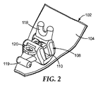
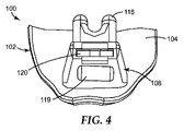
符号100で示されている、一実施形態による舌側歯列矯正装具は、図1〜5の様々な図に示してある。例示されているように、装具100は、内表面104と接合表面106とを有する基部102を含む(図5の遠心側の側面図に示す)。好ましい実施態様において、外表面106は、患者の歯の舌に面する表面への接着接合を促進する全体的な形状を有する。外表面106は、装具100と歯との間の機械的保定を向上させるための穴、切欠き、凹部、逃げ部、部分的に埋め込まれた粒子、メッシュ、化学結合強化材料、マイクロエッチングされた表面、若しくは他の任意の材料、構造、又はそれらの組み合わせを任意に有し得る。
A lingual orthodontic appliance according to one embodiment, indicated at 100, is illustrated in the various views of FIGS. As illustrated, the
内表面104から外方に延在しているのが、本体108である。幾つかの実施形態において、本体108及び基部102は、溶接、半田付け、又は相互に接着的に連結され得る。あるいは、本体108及び基部102は、例えば、インベストメント鋳造法によって、又は幾つかの公知の迅速なプロトタイピング方法のいずれかによって、一体的に形成され得る。細長いアーチワイヤースロット110は、概ね近心側−遠心側方向に沿って咬合側に面する表面を横切って延在し、歯科矯正治療中に好適にサイズ設定されたアーチワイヤーを本体108内に受容できるような配向及び位置を有する。図5に示すように、スロット110は概ね直線状の構成を有し、この構成は、平面状の底部壁112、並びに平面状の唇側及び舌側の側壁114、116を含み、この平面状の唇側及び舌側の側壁はそれぞれ、底部壁112に対して垂直であるか、又は少なくとも実質的に垂直である。
Extending outwardly from the
任意選択的なタイウィング118、及び任意選択的なフック119は、本体108と一体的に形成されて、スロット110内におけるアーチワイヤーの手動結紮を提供し、所望の場合、歯科矯正補助装置の装着を更に提供する。
An
任意選択的に、図示されているように、本体108は基部102に対して配向を有し、底部壁112は、基部102の内表面及び外表面104、106に対して鋭角に配向されている。概ねより垂直配向の、歯の唇側面に接合された装具に関しては、底部壁112は、スロット110の中にアーチワイヤーを挿入する助けとなるよう、内表面及び外表面104、106に略平行であることが好ましい。
Optionally, as shown, the
例示的な実施形態において、基部102、本体108のいずれか一方、又は両方は、ステンレススチール、チタン、又は金の合金のような好適な強度及びモジュラスを有する金属から一体的に製造される。幾つかの実施形態において、装具100は、治療中に目に見える唇側装具であり、その場合、基部102及び/又は本体108は、半透明のセラミック材料から製造され得る。特に好ましいセラミック材料としては、発行済み米国特許第6,648,638号(Castroら)に記載されている微粒子多結晶性アルミナ材料が挙げられる。これらのセラミック材料は、光線を透過して、下にある歯面の色と視覚的に融合することができることから、強度が高いことで公知であり、また金属材料と比較して美観にも優れている。セラミックは、審美的な特性を備えているため、本来的に唇側接合装具に有利であるが、患者がニッケルアレルギー、又は金属に対する他の経口感受性を有する場合、概して舌側装具にもまた有用であり得る。
In the exemplary embodiment, either the
図1〜5に更に示すように、略平面状の弾性クリップ120は、本体108の咬合側の側面内に摺動可能に受容されるとともに、特定の方向からアーチワイヤーがスロット110にアクセスすることが承認又は拒否されるように、開放位置と閉鎖位置との間で移動可能にもなっている。図1〜2はそれぞれ、特に開放位置及び閉鎖位置にあるクリップ120を示している。
As further shown in FIGS. 1-5, the generally planar
クリップ120の更なる態様は、図6により詳細に示されている。図示してあるように、クリップ120は、近心側及び遠心側の支柱122、124と、偏向可能な前部支柱126と、第1及び第2の支柱128、130と、を含む略平面状の矩形構成を有している。近心側及び遠心側の支柱122、124は、本体108にアセンブルされたときに、クリップ120の移動経路に対応する概ね唇側−舌側の方向に沿って延在する。前部支柱126及び後部支柱128、130は、近心側及び遠心側支柱122、124に対して直交に延在し、近心側及び遠心側支柱122、124に相互に接続しており、前部支柱126は、クリップ120の前縁に配置され、後部支柱128、130は、クリップ120の後縁に向かって配置される。
A further aspect of the
近心側及び遠心側支柱122、124は、前部支柱126及び後部支柱128と共に、それぞれ、開放領域132に沿って延在し、開放領域132を画定している。ここに図示してあるように、開放領域132は、クリップ120で完全に封入されているが、必ずしもそうある必要はない。支柱122、124、126、128のうちの1つ以上には、クリップ120の全体的な機能性を損なうことなく、1つ以上の不連続面が存在し得る。
The mesial and
図6に更に示すように、開放領域132は、一対の偏向可能なタブ138、140によって、第1の開放領域134と、その第1の開放領域134に隣接する第2の開放領域136とに更に分割される。タブ138、140は、近心側及び遠心側支柱122、124から相互に向かって内方に突出し、それらの最接近点にて間隙139によって互いから離間されている。要するに、後部支柱128、近心側及び遠心側支柱122、124、並びにタブ138、140が集合的に第1の開放領域134を画定している一方、前部支柱126、近心側及び遠心側支柱122、124、並びにタブ138、140は集合的に第2の開放領域136を画定している。
As further shown in FIG. 6, the
図示した実施形態において、第1及び第2の開放領域134、136は、特定の近心側−遠心側幅で特徴付けられている。第1及び第2の開放領域134、136はほぼ長方形の形状であり、これらの領域134、136の近心側−遠心側幅は、近心側及び遠心側支柱122、124の長さに沿って概ね整合している。幾つかの実施形態において、間隙139は、第1及び第2の開放領域134、136の近心側−遠心側幅の少なくとも0パーセント、少なくとも5パーセント、少なくとも15パーセント、少なくとも45パーセント、又は少なくとも80パーセントの大きさを有する。幾つかの実施形態において、間隙139は、第1及び第2の開放領域134、136の近心側−遠心側幅のせいぜい100パーセント、せいぜい80パーセント、せいぜい60パーセント、せいぜい40パーセント、又はせいぜい20パーセントの大きさを有する。
In the illustrated embodiment, the first and second
また、図6は、近心側及び遠心側支柱122、124で封入された第3の開放領域137、並びに一対の後部支柱128、130も示している。第3の開放領域137は、その舌側の側部上にある第1の開放領域134に隣接しており、クリップ120の操作に用いられる先細手用器械の購入点を提供している。
FIG. 6 also shows a third
クリップ120は、ニッケル及びチタンの合金を主成分とする形状記憶材料のような高弾性ひずみ限界を有する1つ以上の弾性材料から製造されることが好ましいが、クリップ120の反復的開閉過程の間に、ステンレススチール、βチタン、コバルト合金(例えば、Elgiloy Specialty Metals,Elgin,IL製)のような他の材料、又は更には特定の塑性物質も、疲労又は破壊することのない限り、使用され得る。
The
クリップ120と本体108との間の相互作用は、クリップ120と係合する本体108の関連する部分を示す図7〜9を参照することによって、更に明確になり得る。溝142は、本体108の少なくとも一部を通って延在している。図7〜8に示すように、溝142は、クリップ120の近心側及び遠心側支柱122、124(図7〜9では、明確にするため省略してある)を受容するための逃げ部144を有する。図7に示してあるように、逃げ部144は、アーチワイヤースロット110の対向する側面上に配設されており、これにより、スロット110内に受容されたアーチワイヤーによって外向きの圧力が印加される場合でさえも、クリップ120が本体108から係合解除されるのを防止する。図7に示すように、必須ではないが、本体108はまた、アーチワイヤースロット110の両側面上にある溝142の上に及びこの溝142を横切って延在し得る。
The interaction between the
図7〜8を再び参照すると、第1の突出部150及び第2の突出部152は、本体108から基部102に向かう方向へ突き出て、溝142に入り込んでいる。突出部150、152は、アーチワイヤースロット110の対向する側面上にある溝142に沿って配設されている。以降の節で更に説明するように、クリップ20が溝142を通って摺動すると、突出部150、152は、正面及び後部支柱126、128並びにタブ138、140と機械的に相互作用する。この相互作用では、安定な開放及び閉鎖クリップ位置を画定することによって、装具100の操作を促進する。
7 to 8 again, the
図6をもう一度参照すると、前部支柱126及びタブ138、140はそれぞれ、本体108上の開放位置と閉鎖位置との間をクリップ120が摺動可能に移動したときに、クリップ120の平面の外側へ弾性的に屈曲し得るクリップ120の偏向可能部分を表している。そのような実施態様において、クリップの偏向領域は、2つの偏向可能部分(即ち、前部支柱126及びタブ138、140)を含む。クリップ120は、図6に描写されている特徴部を必ずしも全て含む必要はない。例えば、タブ138、140、後部支柱130、及び第3の開放領域137は、クリップ120の簡略化バリアントから省略され得る。このバリアントにおいて、前部支柱126は、クリップ120の偏向可能部分として単独で機能し得る(即ち、偏向領域は、前部支柱126のみ含む)。
Referring again to FIG. 6, the
図10〜13の断面図には、本体108に対して摺動したときのクリップ120の操作が倍尺で示してある。図10は、安定な閉鎖位置にあるクリップ120を示している。第2の突出部152は、第2の開放領域136内に延在し、この第2の開放領域136を占有する(この第2の開放領域は、前部支柱126とタブ138、140との間にある)。第2の突出部152は、全体的な近心側−遠心側幅がタブ138、140間の間隙139より大きいため、第2の突出部152は、通常の治療過程の間に第2の開放領域136内に捕えられる。
In the cross-sectional views of FIGS. 10 to 13, the operation of the
図10に示す構成において、突出部150、152の両方が集合的な開放領域132を占有する。より具体的には、第1の突出部150が第1の開放領域134を占有し、第2の突出部152が第2の開放領域136を占有する。特定の有利な実施態様において、第1及び第2の突出部150、152はそれぞれ、前部及び後部支柱126、128に同時に係合するように、互いに対して配置され得、それにより、図示されている閉鎖位置にあるクリップ120が、不慮にも滑り運動するのを制限する。
In the configuration shown in FIG. 10, both
クリップ120を開放するため、医師は、診査器具の先端部又は他の好適な手用器械を第3の開放領域137に挿入し、舌側摺動力をクリップ120に印加できる。図11は、舌側摺動力が印加された後、その閉鎖位置から開放位置に向かって付勢された、別の位置にあるクリップ120を示す。この図において、本質的に、前部支柱126を含むクリップ120全体が、基準平面160に沿って存在し、アーチワイヤースロット110の入口上に延在する。クリップ120が図11に示す位置まで摺動すると、突出部152が前部支柱126と接触する結果として、更なる摺動に対する抵抗が増した。突出部152を十分な力で付勢すると、図に示すように、クリップ120の前部支柱126は、基準平面160の外側へ弾性的に偏向し、突出部152を横断して、図12に示す部分的に開放されたクリップ構成に到達し得る。
To open the
基準平面160は、クリップ120の摺動方向と概ね同一平面上にある。任意選択的に、図示されているように、基準平面160は、アーチワイヤースロット110の咬合側に面する入口上に延在し、底部壁112に対して平行である。あるいは、基準平面160は、底部壁112に対して多少鋭角にて延在し得る。そのような構成が所望され得るのは、例えば、本体108に対して角度付きのクリップ120によって全体的に低いプロファイル装具100を可能にする場合、又は治療中に患者の頬又は口唇に刺激を与える可能性が回避される方向にクリップ120を整列する場合である。他の実装態様において、基準平面160は、溝142により画定されてもよいし、かつ/又は突出部150、152のうちの1つ以上により画定されてもよい。
The
図12に示すクリップ構成において、第2の突出部152は、第1又は第2の開放領域134、136いずれも占有することなく、クリップ120の外側に位置している。しかしながら、第1の突出部150は、第1の開放領域134内に残り、タブ138、140と接触する。前にも述べたように、十分な力の下では、タブ138、140が基準平面160の外へ弾性的に屈曲するか、又は偏向し、第1の突出部150を横断して、クリップ120が、図13に示すような完全に開放位置を取ることが可能になる。任意選択的に、図示されているように、第1の突出部150は、前部支柱126及びタブ138、140に同時に係合し、クリップ120を開放された状態に保持して、更なる滑り運動を制限する。それ故、クリップ120が閉鎖されているときに、第1及び第2の突出部150、152がそれぞれ第1及び第2の開放領域134、136を占有し、一方、クリップ120が開放されているときに、第1の突出部150が第2の開放領域136を占有し、第2の突出部152は第1及び第2の開放領域134、136をいずれも占有しない。
In the clip configuration shown in FIG. 12, the second projecting
この開放位置から、手用器械を使用してクリップ120の第3の開放領域137において唇側の力を印加することにより、クリップ120を引き続いて閉鎖し得る。所望の場合、医師はまた、他の開放領域134、136(アクセス可能な場合)又は前部又は後部支柱126、128のうちの1つに対して力を向け、クリップ120を摺動可能に閉鎖することができる。クリップ120を閉鎖するプロセスでは、上述の工程を本質的に逆順に追跡する。
From this open position, the
設計上の様々な考慮によって、第1及び第2の突出部150、152並びにタブ138、140の形状及びサイズを知ることができる。例えば、第1の突出部150を第2の突出部152より大きくすることができ、それにより、クリップ120の前部支柱126は、通常のクリップ開離力の下で第2の突出部152を横断できるが同じ力の下では第1の突出部150を横断しないようになり、本体108からクリップ120が完全に取り退けられるのが回避される。クリップ120の開閉力は典型的に、少なくとも0.4N(0.1lbf)、幾つかの実施形態では少なくとも0.9N(0.2lbf)、更に他の実施形態では少なくとも2N(0.4lbf)である。クリップ120の開閉力は典型的に、49N以下(11lbf)であり、幾つかの実施形態では18N以下(4.0lbf)、更に他の実施形態では13N以下(3.0lbf)である。
Through various design considerations, the shape and size of the first and
また、突出部150、152の幾何形状を使用することにより、クリップ120の開閉に必要とされる力を調整できる。例えば、クリップ120の開閉に必要とされる力は、(近心側又は遠心側方向から見て)傾斜側壁に概ね台形プロファイルを有する突出部150、152を使用することにより低減できる。一方又は両方の突出部150、152に対する一方又は両方の側壁は、約60度未満、約45度未満、又は約30度未満の側壁角により特徴付けられ得る。同様に、一方又は両方の突出部150、152は、約45度超、約60度超、又は約75度超の側壁角を有し得る。台形突出部の更なる態様は、2013年3月4日出願の同時係属中の国際出願第PCT/US13/28785号(Yickら)に記載されている。
Moreover, the force required to open and close the
所望の場合、実質的に異なる側壁角を持つ台形突出部を使用することにより、非対称の開閉力が実現され得る。例えば、突出部150、152の一側面が40度の側壁角を有する場合もある一方、突出部150、152の対向する側面が60度の側壁角を有する場合もある。そのような構成を用いることにより、クリップ120の閉鎖に必要とされる力を低減させ得ると同時に、クリップ120を開放するための力の閾値レベルをより高く維持することで、治療中にワイヤーが誤って係合解除されるのを回避し得る。
If desired, an asymmetric opening and closing force can be achieved by using trapezoidal protrusions with substantially different sidewall angles. For example, one side surface of the
また、クリップ120を開放位置と閉鎖位置との間でスナップするのに必要とされる力のレベルは、タブ138、140の形状を修正することによっても調整され得る。例えば、タブ138、140を幅狭にするか、又はタブ138、140の外形に更に丸みを付けることにより、クリップ120を開放するのに必要とされる力が低減され得る。
The level of force required to snap the
更に別の代替として、タブ138、140をクリップ120の別の偏向可能な構成部品で置き換えてもよい。例えば、クリップ120は、代わりに、近心側及び遠心側支柱122、124を相互接続し、かつ、クリップ120が開放されているときに、基準平面160の外側へ偏向し、第1の突出部150を横断するのに十分な可撓性を有する中間的支柱を含んでもよい。
As yet another alternative, the
別の例示的な実施形態は、図14〜16の矯正装具200で表される。装具200は、装具100と同様に、内表面204と、その内表面204から延在している本体208と、近心側−遠心側に延在するアーチワイヤースロット210と、を有する基部202を有し、スロット210上を可逆的に摺動し得るクリップ220も有する。ただし、クリップ200は、技術的に及び機能的に、幾つかの点で装具100とは相違する。
Another exemplary embodiment is represented by the
第1に、クリップ220は、第3の開放領域を画定する一対の後部支柱を有しない。代わりに、クリップ220は、偏向可能な前部支柱226、後部支柱228、及びその近心側支柱222と遠心側支柱224との間に位置する一対の対向するタブ238、240のみを有する。既に述べたように、クリップ220は第1の開放領域234と第2の開放領域236とを有し、両領域は、対向するタブ238、240によって互いから離間されている。しかしながら、この実施形態において、本体208に逃げ部244を有する開放面の溝(open-faced channel)を使用して、クリップ220及び本体208の摺動係合が成し遂げられる。図15に図示してあるように、クリップ220が開放されているとき、本体208は、近心側−遠心側方向に沿ってクリップ220の咬合側の面上を完全に延在しない。
First, the
第1の開放領域234は、従来の実施形態における第1の開放領域134とは異なり、クリップ220の摺動運動の全範囲に沿って、手用器械の尖った先端部に完全にアクセス可能である。第1の開放領域234は、クリップ220を作動させるエクスプローラ又はスカラーのような一般的な手用器械の尖った先端部を収容するのに十分なサイズを有することが好ましい。好都合にも、この構成では、クリップ220をかなり短尺にすることが可能であり、(図14に示すように)クリップ220が閉鎖されているときに、クリップ220の後部支柱228を、本体208の舌側と本質的に同一平面上に存在させることができる。クリップ220が本体208の中に完全に退却されている状態では、治療中に患者に刺激を生じさせる可能性が低くなる。
The first
第2に、装具200は、逆方向に延在する第1の突出部250及び第2の突出部252を含む。第1の突出部250は、一対の副突出部250’、250’’に分岐し、本体208から延出し基部202を離れて略咬合方向へと延び、クリップ220の第1の開放領域234又は第2の236のいずれか一方に入る。第2の突出部252は、本体208から延出し基部202に向かう方向へ(即ち、略歯肉側方向へ)と延び、図14に示すように、クリップ220をその閉鎖位置に保持しているときに、第2の突出部152と同様に作動する。ここで、副突出部250’、250’’は集合的に、第1の突出部250に相当する近心側−遠心側幅を有する。代替として、第2の突出部252はまた、基部204から離れる方向に延在し得る。
Second, the
装具200の更なる態様及び利点は、既に装具100に関して説明したものと類似のものであるので、説明を繰り返す必要はない。
Further aspects and advantages of the
上記実施例において、クリップ120、220は略平面状であり、それぞれの基準平面160、260に沿って概ね整列される。代替として、クリップ120、220は、湾曲面に沿って摺動経路が画定される僅かな湾曲を有し得る。これらの実施例において、基準平面160、260は、湾曲面にほぼ接する平面として表され得る。それぞれの基部102、202に向かって湾曲するクリップ120、220を使用すると装具100、200の全体的なプロファイルを縮小させるうえで有益である場合があり、特に、クリップ120、220が閉鎖状態のときに本体108、208を超えて突出する場合に、患者の快適さを向上させ得る。
In the above embodiment, the
全体的な装具プロファイルを減ずるための別のアプローチを例証する、更に別の実施形態に従う装具300を、図17に示す。同図において、装具300はクリップ320を含み、このクリップ320は、装具300においてアーチワイヤー50を保持している状態で図示されている。クリップ320は、殆どの点においてクリップ220に類似しているが、異なる点は、クリップ320の舌側に、クリップ320の残部に対して特定の角度で屈曲した付加的な弁395が含まれることである。弁395は、装具300の基部に向かう角度にて配向されており、全体的に低いプロファイルの保持を助けながらクリップ320に係合するための購入点を提供する。
A
クリップ120、220、320は、歯科矯正治療の過程の間に典型的にアーチワイヤーが課した力に応答して、弾力を発揮するだけでなく有意に撓曲する能力もあることが好ましい。可撓性クリップを使用することにより、アーチワイヤーが、広可動域わたって力を装具に付与し、結果として「能動的な結紮」に帰結する構成が可能となる。
The
図18は、能動的な結紮を提供する更に別の実施形態に従う、歯列矯正装具400の関連部分を示している。図示されているように、装具は、アーチワイヤースロット410の対向する側面上に位置する突出部450、452を有する本体408を含む。前の実施形態から理解されるように、突出部405、452がクリップ420をその閉鎖位置に着脱自在に係止した状態が示されている。溝442に沿って摺動するクリップ420は、略舌側方向に面する入口を有する空洞486内に部分的に受容される。空洞486は、装具400の基部(不図示)に向かって略歯肉側方向に傾斜する角度付きの壁488を含む。クリップ420は、角度付きの壁488に接触した結果、歯肉側方向に向かって偏向し、クリップ420とスロット410の底部壁との間の空間を縮小させる。
FIG. 18 shows relevant portions of
任意選択的に、角度付きの壁488は、所望程度の活性がもたらされるように、溝442に対して任意の好適な配向を取り得る。例えば、角度付きの壁488の勾配を大きくすると、クリップ420の偏向が大きくなり、スロット410内部の空間が更に縮小する。この修正の結果、スロット410内部の結紮アーチワイヤーの運動の受動的範囲が狭まる。対照的に、能動的な結紮の範囲は、クリップ420が、アーチワイヤーが及ぼした咬合側の力に応答して、装具400の基部から離れて咬合側方向へ向かって偏向することが可能なため、増大する。幾つかの実施形態において、アーチワイヤーが特定の所定の閾値を超える断面寸法を有する場合は常に、角度付きの壁488は、「能動的な結紮」を可能にする間隔及び配向を有し得る。
Optionally, angled
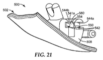
別の例示的な実施形態は、図19〜22において歯列矯正装具500で表される。装具500は、装具200と同様に、内表面504を有する基部502と、内表面504から延出する本体508と、近心側−遠心側に延在するアーチワイヤースロット510と、を有し、クリップ520は、スロット510上に可逆的に摺動可能。装具500の更なる態様及び利点は、既に装具100及び200に関して説明したものと類似であるので、説明を繰り返す必要はない。しかしながら、装具500は、技術的に及び機能的に、幾つかの相違点装具100及び200とは相違する。
Another exemplary embodiment is represented by
第1に、クリップ520は、連続的な前部支柱を含まず、典型的にクリップ120及び220よりも幅が広い。代わりに、クリップ520は、2つの偏向可能な前部支柱526及び227、後部支柱528、並びにその近心側支柱522と遠心側支柱524との間に位置する一対の対向するタブ538、540により特徴付けられる。クリップ220におけるのと同様、描写された実施形態におけるクリップ520は、第1の開放領域534と第2の開放領域536とを有し、この第1の開放領域及び第2の開放領域は、対向するタブ538、540によって互いから離間されている。タブ538、540は、近心側及び遠心側支柱522、524から相互に向かって内方に突出し、それらの最接近点にて間隙539によって互いから離間されている。同様に、前部支柱525及び225は、近心側及び遠心側支柱522、524から相互に向かって内方へ突出し、それらの最接近点にて間隙527によって互いから離間されている。前部支柱525、526間の間隙527は典型的に、下記に説明する理由ゆえに間隙539よりも小さい。
First,
第2に、装具500は、本体508における近心側−遠心側逃げ部544、545により部分的に画定された、互いに異なる第1及び第2の溝542、543を含む。逃げ部544、545は、本体508の近心側及び遠心側表面から延出し中心に向かって延び、開放溝542、543及び中心支持部541を作成している。中心支持部541は、近心側壁部分541aと遠心側壁部分541bとを含む。図19に図示してあるように、クリップ520の近心側及び遠心側支柱522、524は、溝542、543に受容され、中心支持部541をまたいでいる。クリップ520は舌側−唇側を有し、本体508に対する近心側−遠心側の動きの自由を制限する。各々の溝542、543は、咬合側方向に(例えば、概ね突出部550、552より上に)、タブ538、540及び/又は支柱525、526の偏向部を収容するための、追加的な領域を含み得る。これらの追加的な領域により、逃げ部544a、545aの残りの部分の高さ(咬合側−歯肉側)を、近心側及び遠心側支柱522、524の厚さに実質的に(例えば、1mm以内に)近似させることが可能である。所望の場合、クリップ520と溝542、543との間の嵌合を比較的緊密にすることにより、通常の治療過程の間、アーチワイヤーの舌側−唇側移動を制限する助けになり得る。
Second, the
中心支持部541に対向するアーチワイヤースロット510の側面上に、追加的な逃げ部544b、545bを作成し得る。この追加的な逃げ部544b、545bは、アーチワイヤースロット510わたってクリップ520が閉鎖されたときにクリップ520の前部支柱525、526を受容する。逃げ部544b、545bは、2つの互いに異なる溝として描写されているが、前部支柱525、526を受容するための連続的な溝を形成し得る。特定の状況において、2つの溝を作ることにより、クリップ520と本体508との間に追加的な干渉嵌合が提供され、開放状態と閉鎖状態との間での所望されないクリップの動きの減少又は排除が更に強化され得る。
図20〜21により明瞭に示すように、第1の突出部550及び第2の突出部552は、中心支持部541の近心側及び遠心側壁部分541a、541bから突き出ている。第1及び第2の突出部550、552はそれぞれ角度付きの壁部分を含み、それらの壁部分は、クリップが開放状態(図19)及び閉鎖状態で移動する際に、タブ538、540をクリップ520の平面の外側へ偏向させる助けになる。閉鎖状態(図示せず)において、突出部550、552は、タブ538、540と後部支柱528との間にある開放領域を占有する。中心部分541の近心側−遠心側幅と突出部550、552の基部との組み合わせは、タブ538、540間の間隙539よりも大きく、これは、通常の治療過程の間にクリップ520が意図せずに開放される可能性を実質的に減らす。また、突出部550、552の幾何形状は、角柱形の傾斜部として描いてあるが、(装具100について述べたように)上記の修正を施すことによって、クリップ520の開放及び閉鎖に必要とされる力を調整し得る。
As clearly shown in FIGS. 20 to 21, the
溝542、543の一方又は両方は、クリップ520が開放位置に移動したときに、対応する前部支柱(525、526)に当接する止め具554を含み得る。止め具554は、中心支持部541の近心側壁541a及び/又は遠心側壁部分541bから外方へ延出する棚状物又は他の露出部の形態を取り得る。止め具554は、突出部550の近位の位置にて、中心支持部541の近心側−遠心側幅を増分させて、クリップ520の望ましくない動きを阻害するための表面を与える。クリップがアーチワイヤースロットから離れる方向へ移動すると、止め具554は、前部支柱525、526の一方又は両方に係合し、更なる動きを阻害又は防止する。この干渉を成し遂げるため、止め具554は、中心支持部541の近心側−遠心側幅を、少なくともクリップ520の間隙527の幅まで効果的に増分する。特定の状況においては、中心部分541の幅を前部間隙527の幅よりも大きい幅になるように増分させることが、554にとって好都合であり得る。当然のことながら、止め具554における中心支持部541の幅は、典型的に、タブ538、540間の間隙539の幅よりも狭くなる。止め具554で近心側−遠心側幅を間隙539より大きくすることにより、クリップ520の閉鎖及び開放時に過度の干渉が生ずる可能性がある。この原因は、動きを継続するには、タブ538、540を平面の外側へ偏向させかつ近心側及び遠心側支柱522、524を本体508から外方へ偏向させるのに十分な力が必要とされるためである。しかしながら、そのような構成は特定の状況において許容され得る。
One or both of the
装具500の本体508及びクリップ520を特徴とするブラケットは、幾つかの利点を提供し得る。特定の状況下においては、逃げ部544、545が本体508の近心側−遠心側の側部からのアクセスを提供するため、溝542、543の構造をより作り易くし得る。結果として、別個の前部支柱525、526によって、クリップ520の平面内で近心側及び遠心側支柱522、524の偏向が可能になるため、クリップ520を初めに溝542、543に挿入するのが容易化され得る。この偏向により、クリップ520が最初にアーチワイヤースロット510に向かった位置に移動するため、突出部550、552を横断するのに必要な力を低減又は除去できる。
A bracket featuring the
そのうえ、中心支持部541の各側面上の2つの開放溝542、543を使用することにより、アーチワイヤースロット510の長さに対して増分された近心側−遠心側幅寸法をクリップ520に含めることを可能にする。装具100及び200において、クリップが本体と係合しているときに、溝を画定している本体部分が近心側及び遠心側支柱の外側にあるため、クリップ120、220はアーチワイヤースロットの全長を必ずしも延長できるとは限らない。対照的に、クリップ520は、溝542及び543によって近心側及び遠心側の開口を設けることで、少なくともアーチワイヤースロットの長さまで延在することが可能になり、幾つかの実施形態においては、スロット510の近心側−遠心側の長さを超える幅まで延在することも可能になる。近心側支柱522と遠心側524との間の幅寸法を増分すると、通常の治療過程の間にアーチワイヤースロット510内に配設されたクリップ520とアーチワイヤーとの間の接触点間の全長の増分に役立つ。特定の状況において、近心側支柱と遠心側支柱との間にまたがる幅広なクリップは、各スロットの配向を、歯表面を基準として、垂直スロットを有する装具に対しては改良型の先端制御を提供し、水平スロットを有する装具に対しては回旋制御を提供するものである。
In addition, the
実施形態
1.歯科矯正装具であって、
歯に取り付けるための接合表面を有する基部と、基部から外方に延在する本体であって、その本体上に細長いスロットが概ね近心側−遠心側方向に沿って延在する、本体と、本体の上に配設された第1及び第2の突出部と、本体に摺動可能に係合されたかつ開放位置と閉鎖位置との間で移動可能なクリップを備え、クリップが、スロット上に延在する基準平面に沿って整列された少なくとも1つの偏向可能部分を含み、クリップが開放位置と閉鎖位置との間を移動すると、少なくとも1つの偏向可能部分が、基準平面の外側へ弾性的に屈曲し、第2の突出部を横断する、歯科矯正装具。
2.スロットが第1の突出部と第2の突出部との間に延在し、第1の突出部がクリップ内に延在してクリップを干渉嵌合にある本体に保持し、第2の突出部が、閉鎖位置にあるクリップ内に選択的に延在する、実施形態1に記載の歯科矯正装具。
3.本体上に一対の逃げ溝を更に備え、クリップが、一対の逃げ溝に受容された近心側及び遠心側の支柱を更に含む、実施形態1に記載の歯科矯正装具。
4.クリップが、近心側支柱と遠心側支柱との間に位置付けられた第1及び第2の開放領域を更に含み、少なくとも1つの偏向可能部分が、第1及び第2の開放領域を互いから離隔させている、実施形態2に記載の歯科矯正装具。
5.クリップが閉鎖されているときには第1及び第2の突出部が異なる開放領域を占有する一方、クリップが開放されているときには第1の突出部が該2の開放領域を占有し、第2の突出部がいずれの開放領域も占有しない、実施形態4に記載の歯科矯正装具。
6.歯科矯正装具であって、
歯に取り付けるための接合表面を有する基部と、
基部から外方に延在するし、かつ概ね近心側−遠心側の方向に沿って延在する、長いスロットを有する、本体と、
開放位置と閉鎖位置との間でのクリップの動きを可能にするように本体に摺動可能に係合された近心側及び遠心側の支柱、近心側支柱と遠心側支柱との間に位置付けられた開放領域と、を含む弾性クリップと、
本体上に配設された第1及び第2の突出部であって、スロットが間に延在している、第1及び第2の突出部と、
を備え、クリップが閉鎖されているとき、両方の突出部が開放領域を占有し、クリップが開放されているとき、第1の突出部のみが開放領域を占有する、歯科矯正装具。
7.開放領域が第1の開放領域を含み、開放領域に隣接した第2の開放領域を更に含み、少なくとも1つの偏向可能部分が、第1及び第2の開放領域を互いから離隔させている、実施形態6に記載の歯科矯正装具。
8.少なくとも1つの偏向可能部分が、スロット上に延在する基準平面に沿って整列されており、クリップが開放位置と閉鎖位置との間を摺動すると、偏向可能部分が、基準平面の外側へ弾性的に屈曲して第1の突出部を横断する、実施形態6に記載の歯科矯正装具。
9.少なくとも1つの偏向可能部分が、近心側及び遠心側支柱から相互に向かって内方に突出する一対のタブを含む、実施形態4〜8のいずれか1つに記載の歯科矯正装具。
10.開放領域が近心側−遠心側幅を有し、一対のタブが、特定の近心側−遠心側幅の5%〜80%の範囲に及ぶ間隙だけ離間されている、実施形態9に記載の歯科矯正装具。
11.間隙が、特定の近心側−遠心側幅の15%〜60%の範囲に及ぶ、実施形態10に記載の歯科矯正装具。
12.間隙が、特定の近心側−遠心側幅の45%〜60%の範囲に及ぶ、実施形態10に記載の歯科矯正装具。
13.第2の突出部の全体的な近心側−遠心側幅が、特定の近心側−遠心側幅よりも大きい、実施形態10に記載の歯科矯正装具。
14.第2の突出部が、全体的な近心側−遠心側幅を集合的に有する2つ以上の副突出部を含む、実施形態13に記載の歯科矯正装具。
15.第1の突出部が基部から離れる方向に概ね延在する一方で、第2の突出部が基部に向かう方向に概ね延在する、実施形態1〜14のいずれか1つに記載の歯科矯正装具。
16.第1及び第2の突出部の両方が、基部から離れる方向に又は基部に向かう方向に概ね延在する、実施形態1〜15のいずれか1つに記載の歯科矯正装具。
17.第2の開放領域が、近心側及び遠心側支柱、並びに少なくとも1つの偏向可能部分により集合的に画定されており、少なくとも1つの偏向可能部分が、近心側及び遠心側支柱を相互に接続する前部支柱を含む、実施形態4及び8〜16のいずれか1つに記載の歯科矯正装具。
18.クリップが、近心側及び遠心側支柱を相互に接続する後部支柱を更に含み、後部支柱、近心側及び遠心側支柱、並びに少なくとも1つの偏向可能部分が、第1の開放領域を集合的に画定する、実施形態17に記載の歯科矯正装具。
19.クリップが閉鎖位置にある間、第1及び第2の突出部がそれぞれ前部及び後部支柱に同時に係合し、クリップの滑り運動を制限する、実施形態18に記載の歯科矯正装具。
20.クリップが開放位置にあるときに、第1の突出部が同時に前部支柱及び少なくとも1つの偏向可能部分に係合し、クリップの滑り運動を制限する、実施形態18に記載の歯科矯正装具。
21.本体が、第2の突出部に隣接した傾斜壁を含み、クリップが閉鎖されているときに、角度付きの壁が、前部支柱に接触し、クリップを基部に対して付勢する、実施形態17に記載の歯科矯正装具。
22.少なくとも1つの偏向可能部分が、近心側及び遠心側支柱を相互接続する中間的支柱を含む、実施形態5及び7〜21のいずれか1つに記載の歯科矯正装具。
23.全体的なクリップが、基準平面に沿って概ね整列される、実施形態1〜22のいずれか1つに記載の歯科矯正装具。
24.スロットが、一対の対向する側壁と側壁に直交する底部壁とを有し、基準平面が底部壁に対して略平行である、実施形態1〜23のいずれか1つに記載の歯科矯正装具。
25.歯科矯正用装具を使用する方法であって、
基部と、基部から外方に延在する本体と、基部上に配設された概ね近心側−遠心側の方向に沿って延在する細長いスロットと、スロットの対向する側面上にある本体上に位置する第1及び第2の突出部と、を備える装具を提供する工程と、本体に摺動可能に係合された開放領域を有するクリップを提供する工程であって、第1の突出部が開放領域を占有して、干渉嵌合にあるクリップを保持しており、第2の突出部が開放領域の外側に存在する、工程と、クリップを開放位置から閉鎖位置に向かって摺動させ、それにより、クリップの第1の偏向可能部分を第2の突出部に対して付勢する工程と、第1の偏向可能部分を弾性的に屈曲させ、クリップに第2の突出部を横断させ、第1及び第2の突出部の両方を開放領域内に配置して、クリップを閉鎖位置に保持することを可能にする工程と、を含む、方法。
26.開放領域が、第1の開放領域と、開放領域に隣接した第2の開放領域と、を含み、第1及び第2の開放領域を互いから離隔させている第2の偏向可能部分を更に含む、実施形態25に記載の歯科矯正装具。
27.第2の偏向可能部分が、スロット上に延在する基準平面に沿って整列されており、クリップがその閉鎖位置に向かって摺動すると、第2の偏向可能部分が基準平面の外側へ弾性的に屈曲して、第1の突出部を横断する工程を更に含む、実施形態26に記載の方法。
28.クリップが、近心側及び遠心側の支柱を更に含み、第2の偏向可能部分が、近心側及び遠心側支柱から内方に突出する一対のタブを含む、実施形態26に記載の方法。
Embodiment 1. Orthodontic appliances,
A base having a joining surface for attachment to a tooth; and a body extending outwardly from the base, wherein an elongated slot extends generally along the mesial-distal direction on the body; First and second protrusions disposed on the body, and a clip slidably engaged with the body and movable between an open position and a closed position, the clip being on the slot At least one deflectable portion aligned along a reference plane extending to the at least one deflectable portion when the clip moves between an open position and a closed position. An orthodontic appliance that bends to the cross and crosses the second protrusion.
2. A slot extends between the first protrusion and the second protrusion, the first protrusion extends into the clip and holds the clip to the body in interference fit, and the second protrusion The orthodontic appliance according to embodiment 1, wherein the portion selectively extends within the clip in the closed position.
3. The orthodontic appliance according to embodiment 1, further comprising a pair of relief grooves on the body, wherein the clip further includes mesial and distal struts received in the pair of relief grooves.
4). The clip further includes first and second open regions positioned between the mesial and distal columns and at least one deflectable portion separates the first and second open regions from each other. The orthodontic appliance according to embodiment 2, wherein
5. When the clip is closed, the first and second protrusions occupy different open areas, while when the clip is open, the first protrusion occupies the two open areas and the second protrusion The orthodontic appliance according to embodiment 4, wherein the part does not occupy any open area.
6). Orthodontic appliances,
A base having a bonding surface for attachment to a tooth;
A body having a long slot extending outwardly from the base and extending generally along the mesial-distal direction;
A mesial and distal strut slidably engaged with the body to allow movement of the clip between the open and closed positions, between the mesial and distal struts An elastic clip including an open region positioned;
First and second protrusions disposed on the body, wherein the slots extend between the first and second protrusions;
Orthodontic appliances, wherein both protrusions occupy an open area when the clip is closed and only the first protrusion occupies the open area when the clip is open.
7). An implementation wherein the open area includes a first open area, further includes a second open area adjacent to the open area, and at least one deflectable portion separates the first and second open areas from each other. The orthodontic appliance according to claim 6.
8). At least one deflectable portion is aligned along a reference plane extending over the slot, and when the clip slides between an open position and a closed position, the deflectable portion is elastically moved out of the reference plane. The orthodontic appliance according to embodiment 6, wherein the orthodontic appliance is bent flexibly and crosses the first protrusion.
9. 9. The orthodontic appliance according to any one of embodiments 4-8, wherein the at least one deflectable portion includes a pair of tabs that project inwardly toward each other from the mesial and distal struts.
10. Embodiment 9 wherein the open region has a mesial-distal side width and the pair of tabs are separated by a gap ranging from 5% to 80% of a particular mesial-distal side width. Orthodontic appliances.
11. The orthodontic appliance according to embodiment 10, wherein the gap ranges from 15% to 60% of the specific mesial-distal width.
12 The orthodontic appliance according to embodiment 10, wherein the gap ranges from 45% to 60% of the specific mesial-distal width.
13. The orthodontic appliance according to embodiment 10, wherein the overall mesial side-distal side width of the second protrusion is greater than the specific mesial side-distal side width.
14 The orthodontic appliance according to embodiment 13, wherein the second protrusion includes two or more secondary protrusions collectively having an overall mesial-distal width.
15. The orthodontic appliance according to any one of embodiments 1-14, wherein the first protrusion extends generally in a direction away from the base, while the second protrusion extends generally in a direction toward the base. .
16. The orthodontic appliance according to any one of embodiments 1-15, wherein both the first and second protrusions generally extend in a direction away from or toward the base.
17. A second open region is collectively defined by the mesial and distal struts and at least one deflectable portion, the at least one deflectable portion interconnecting the mesial and distal struts 17. The orthodontic appliance according to any one of embodiments 4 and 8-16, including a front strut that performs.
18. The clip further includes a rear strut interconnecting the mesial and distal struts, and the posterior strut, the mesial and distal struts, and the at least one deflectable portion collectively collect the first open region. 18. An orthodontic appliance according to embodiment 17, wherein the orthodontic appliance is defined.
19. The orthodontic appliance according to embodiment 18, wherein the first and second protrusions simultaneously engage the front and rear struts, respectively, to limit the sliding movement of the clip while the clip is in the closed position.
20. The orthodontic appliance according to embodiment 18, wherein the first protrusion simultaneously engages the front strut and the at least one deflectable portion to limit the sliding movement of the clip when the clip is in the open position.
21. Embodiment in which the body includes an inclined wall adjacent to the second protrusion, and the angled wall contacts the front strut and biases the clip against the base when the clip is closed The orthodontic appliance according to claim 17.
22. Embodiment 24. The orthodontic appliance according to any one of embodiments 5 and 7-21, wherein the at least one deflectable portion comprises an intermediate strut interconnecting the mesial and distal struts.
23. Embodiment 23. The orthodontic appliance according to any one of embodiments 1-22, wherein the overall clip is generally aligned along a reference plane.
24. The orthodontic appliance according to any one of embodiments 1-23, wherein the slot has a pair of opposing side walls and a bottom wall orthogonal to the side walls, and the reference plane is substantially parallel to the bottom wall.
25. A method of using orthodontic appliances,
A base, a body extending outwardly from the base, an elongated slot disposed on the base and extending generally in a mesial-distal direction, and on a body on opposite sides of the slot Providing a brace comprising first and second protrusions located on the body, and providing a clip having an open region slidably engaged with the body, the first protrusion Occupying the open area and holding the clip in interference fit, and the second protrusion is outside the open area, and sliding the clip from the open position to the closed position Thereby urging the first deflectable portion of the clip against the second protrusion; and flexibly bending the first deflectable portion to cause the clip to traverse the second protrusion. , Clip both the first and second protrusions in the open area And a step making it possible to hold the closed position, the method.
26. The open area includes a first open area and a second open area adjacent to the open area, and further includes a second deflectable portion that separates the first and second open areas from each other. An orthodontic appliance according to embodiment 25.
27. The second deflectable portion is aligned along a reference plane extending over the slot, and when the clip slides toward its closed position, the second deflectable portion is elastically moved out of the reference plane. 27. The method of embodiment 26, further comprising the step of bending to cross the first protrusion.
28. 27. The method of embodiment 26, wherein the clip further includes mesial and distal struts and the second deflectable portion includes a pair of tabs projecting inwardly from the mesial and distal struts.
上述の特許及び特許出願の全ては、本明細書においてここに明示的に援用されている。上記の発明は、明瞭さ及び理解を目的として、図及び実施例によってある程度詳細に述べたものである。しかしながら、様々な代替物、修正物、及び等価物が用いられ得るため、上記の説明は、以下の「特許請求の範囲」及びその等価物によって定義される本発明の範囲を限定するものと見なされるべきではない。 All of the aforementioned patents and patent applications are hereby expressly incorporated herein. The foregoing invention has been described in some detail by way of illustration and example for purposes of clarity and understanding. However, since various alternatives, modifications, and equivalents may be used, the above description is considered to limit the scope of the invention as defined by the following “claims” and their equivalents. Should not be.
Claims (3)
歯に取り付けるための接合表面を有する基部と、
前記基部から外方に延在する本体であって、該本体上に細長いスロットが概ね近心側−遠心側の方向に沿って延在する、本体と、
前記本体の上に配設された第1及び第2の突出部であって、それらの間に前記スロットが延在し、前記第2の突出部が、前記基部に向かう方向に延在する、第1及び第2の突出部と、
前記本体に摺動可能に係合されかつ開放位置と閉鎖位置との間で移動可能なクリップと、を備え、前記クリップが、前記スロット上に延在する基準平面に沿って整列された少なくとも1つの偏向可能部分を含み、前記クリップが開放位置と閉鎖位置との間を移動すると、前記少なくとも1つの偏向可能部分が、前記基部に向かう方向に前記基準平面の外側へ弾性的に屈曲して前記第2の突出部を横断し、
前記本体上に一対の逃げ溝を更に備え、前記クリップが、前記一対の逃げ溝に受容された近心側支柱及び遠心側支柱を更に含み、
前記クリップが、前記近心側支柱と遠心側支柱との間に位置付けられた第1及び第2の開放領域を更に含み、前記少なくとも1つの偏向可能部分が、前記第1及び第2の開放領域を互いから離隔させており、前記クリップが閉鎖されているときには前記第1及び第2の突出部が異なる開放領域を占有する一方、前記クリップが開放されているときには前記第1の突出部が前記第2の開放領域を占有し、前記第2の突出部がいずれの開放領域も占有しない、歯科矯正装具。 Orthodontic appliances,
A base having a bonding surface for attachment to a tooth;
A body extending outwardly from the base, wherein an elongated slot extends generally along the mesial-distal direction on the body;
First and second protrusions disposed on the main body, the slot extending between them, and the second protrusion extending in a direction toward the base, First and second protrusions;
A clip slidably engaged with the body and movable between an open position and a closed position, wherein the clip is aligned along a reference plane extending over the slot Including at least one deflectable portion, and when the clip moves between an open position and a closed position, the at least one deflectable portion elastically bends out of the reference plane in a direction toward the base. Cross the second protrusion,
The main body further includes a pair of relief grooves, and the clip further includes a mesial side column and a centrifugal side column received in the pair of relief grooves,
The clip further includes first and second open regions positioned between the mesial column and the distal column, and the at least one deflectable portion includes the first and second open regions. Are separated from each other, and when the clip is closed, the first and second protrusions occupy different open areas, whereas when the clip is open, the first protrusion is the An orthodontic appliance that occupies a second open area and wherein the second protrusion does not occupy any open area.
基部と、前記基部から外方に延在する本体と、前記基部上に配設され概ね近心側−遠心側の方向に沿って延在する細長いスロットと、を備える前記装具を提供する工程と、
前記本体に摺動可能に係合される開放領域を有するクリップを提供する工程と、
前記クリップが開放位置から閉鎖位置に向かって摺動したことにより、前記クリップの第1の偏向可能部分を第2の突出部に対して付勢する工程と、
前記第1の偏向可能部分が前記基部に向かう方向に弾性的に屈曲し、前記クリップに前記第2の突出部を横断し、前記第1及び第2の突出部の両方が前記開放領域内に配置されたことにより、前記クリップを前記閉鎖位置に保持する工程と、を含む、方法。 A method for operating an orthodontic appliance according to claim 1 ,
Providing the brace comprising: a base; a body extending outwardly from the base; and an elongated slot disposed on the base and extending generally along a mesial-distal direction. ,
Providing a clip having an open region slidably engaged with the body;
Urging the first deflectable portion of the clip against the second protrusion by sliding the clip from the open position toward the closed position;
The first deflectable portion elastically bends in a direction toward the base, traverses the second protrusion to the clip, and both the first and second protrusions are within the open region; Holding the clip in the closed position by being disposed.
Applications Claiming Priority (3)
| Application Number | Priority Date | Filing Date | Title |
|---|---|---|---|
| US201361794303P | 2013-03-15 | 2013-03-15 | |
| US61/794,303 | 2013-03-15 | ||
| PCT/US2014/028433 WO2014144145A1 (en) | 2013-03-15 | 2014-03-14 | Self-ligating orthodontic appliance |
Publications (3)
| Publication Number | Publication Date |
|---|---|
| JP2016515885A JP2016515885A (en) | 2016-06-02 |
| JP2016515885A5 JP2016515885A5 (en) | 2017-04-13 |
| JP6441304B2 true JP6441304B2 (en) | 2018-12-19 |
Family
ID=51528550
Family Applications (1)
| Application Number | Title | Priority Date | Filing Date |
|---|---|---|---|
| JP2016502787A Expired - Fee Related JP6441304B2 (en) | 2013-03-15 | 2014-03-14 | Orthodontic appliance and method of operating the same |
Country Status (5)
| Country | Link |
|---|---|
| US (1) | US9289274B2 (en) |
| EP (1) | EP2967759A4 (en) |
| JP (1) | JP6441304B2 (en) |
| CN (1) | CN105073061B (en) |
| WO (1) | WO2014144145A1 (en) |
Families Citing this family (7)
| Publication number | Priority date | Publication date | Assignee | Title |
|---|---|---|---|---|
| EP2783656B1 (en) | 2013-03-15 | 2017-06-28 | American Orthodontics Corporation | Self-ligating bracket |
| BR102014013775B1 (en) * | 2014-06-06 | 2021-08-31 | Alexandre Gallo Lopes | Self-ligating bracket system with passive or interactive clip |
| US10111731B2 (en) | 2014-11-18 | 2018-10-30 | American Orthodontics Corporation | Self-ligating bracket |
| US10080628B2 (en) * | 2015-06-08 | 2018-09-25 | American Orthodontics Corporation | Self-ligating bracket |
| JP7153571B2 (en) | 2016-06-30 | 2022-10-14 | スリーエム イノベイティブ プロパティズ カンパニー | self-ligating orthodontic bracket |
| EP3764939B1 (en) | 2018-03-12 | 2023-01-04 | 3M Innovative Properties Company | Packaged orthodontic appliances |
| US11259899B2 (en) | 2020-07-03 | 2022-03-01 | Aadvance Technologies, Llc | Orthodontic device |
Family Cites Families (19)
| Publication number | Priority date | Publication date | Assignee | Title |
|---|---|---|---|---|
| US4492573A (en) * | 1984-03-27 | 1985-01-08 | Augusta Developments Inc. | Orthodontic bracket |
| US5913680A (en) * | 1994-03-07 | 1999-06-22 | Voudouris; John C. | Orthodontic bracket |
| JP4659991B2 (en) * | 2001-02-28 | 2011-03-30 | トミー株式会社 | Orthodontic bracket |
| JP4411573B2 (en) * | 2001-08-24 | 2010-02-10 | トミー株式会社 | Orthodontic bracket |
| US6776614B2 (en) | 2002-02-13 | 2004-08-17 | Lingualcare, Inc. | Modular system for customized orthodontic appliances |
| US7751925B2 (en) | 2006-01-27 | 2010-07-06 | 3M Innovative Properties Company | System to manufacture custom orthodontic appliances, program product, and related methods |
| US7674110B2 (en) * | 2006-03-23 | 2010-03-09 | Ormco Corporation | Low profile self-ligating orthodontic brackets and methods of using such orthodontic brackets |
| DE102006053215B4 (en) * | 2006-11-11 | 2009-10-22 | Bernhard Förster Gmbh | Self-ligating bracket for orthodontics |
| WO2009057937A2 (en) * | 2007-11-01 | 2009-05-07 | Hubit Co., Ltd. | Self-ligating brackets |
| US20100112508A1 (en) * | 2008-11-03 | 2010-05-06 | Alexandre Gallo Lopes | Reversible auto-linked bracket of low profile with double lock |
| DE102008060820A1 (en) * | 2008-12-05 | 2010-06-10 | Bernhard Förster Gmbh | Self-ligating bracket for orthodontics |
| CN201389089Y (en) * | 2009-04-28 | 2010-01-27 | 黄靖慧 | Slide cover type tooth rectifier structure |
| US20100285420A1 (en) * | 2009-05-07 | 2010-11-11 | Ormco Corporation | Orthodontic bracket having a lingually biased closure member and associated method |
| US8636507B2 (en) * | 2009-06-03 | 2014-01-28 | John C. Voudouris | Self-ligating orthodontic bracket |
| CN201529166U (en) * | 2009-08-24 | 2010-07-21 | 倪其军 | Self-locking bracket for teeth orthodontics |
| US8414292B2 (en) * | 2010-08-02 | 2013-04-09 | Alexandre Gallo Lopes | Self ligating bracket system |
| JP5154715B2 (en) * | 2010-09-17 | 2013-02-27 | トミー株式会社 | Orthodontic bracket |
| US8029276B1 (en) * | 2010-09-23 | 2011-10-04 | Robert Lokar | Self-ligating orthodontic bracket |
| US20120270175A1 (en) * | 2011-04-20 | 2012-10-25 | Specialty Appliance Works, Inc. | Self-ligating bracket for orthodontic treatment |
-
2014
- 2014-03-14 JP JP2016502787A patent/JP6441304B2/en not_active Expired - Fee Related
- 2014-03-14 WO PCT/US2014/028433 patent/WO2014144145A1/en active Application Filing
- 2014-03-14 CN CN201480016020.6A patent/CN105073061B/en not_active Expired - Fee Related
- 2014-03-14 EP EP14764115.3A patent/EP2967759A4/en not_active Withdrawn
- 2014-03-14 US US14/212,579 patent/US9289274B2/en not_active Expired - Fee Related
Also Published As
| Publication number | Publication date |
|---|---|
| US20140272750A1 (en) | 2014-09-18 |
| CN105073061A (en) | 2015-11-18 |
| US9289274B2 (en) | 2016-03-22 |
| EP2967759A4 (en) | 2016-11-09 |
| EP2967759A1 (en) | 2016-01-20 |
| CN105073061B (en) | 2019-01-18 |
| WO2014144145A1 (en) | 2014-09-18 |
| JP2016515885A (en) | 2016-06-02 |
Similar Documents
| Publication | Publication Date | Title |
|---|---|---|
| JP6846326B2 (en) | Self-ligating orthodontic bracket | |
| JP7153571B2 (en) | self-ligating orthodontic bracket | |
| JP6441304B2 (en) | Orthodontic appliance and method of operating the same | |
| US7857618B2 (en) | Orthodontic bracket including mechanism for reducing slot width for early torque control | |
| US20060003282A1 (en) | Shape memory self-ligating orthodontic brackets | |
| US20150173859A1 (en) | Orthodontic appliance with ligating feature | |
| JP2020511266A (en) | Self-ligating bracket with ligating member | |
| JP7326300B2 (en) | Ceramic self-ligating bracket with high labial tensile strength | |
| US20230165663A1 (en) | Self-ligating orthodontic bracket |
Legal Events
| Date | Code | Title | Description |
|---|---|---|---|
| A521 | Request for written amendment filed |
Free format text: JAPANESE INTERMEDIATE CODE: A523 Effective date: 20170308 |
|
| A621 | Written request for application examination |
Free format text: JAPANESE INTERMEDIATE CODE: A621 Effective date: 20170308 |
|
| A977 | Report on retrieval |
Free format text: JAPANESE INTERMEDIATE CODE: A971007 Effective date: 20180117 |
|
| A131 | Notification of reasons for refusal |
Free format text: JAPANESE INTERMEDIATE CODE: A131 Effective date: 20180123 |
|
| RD03 | Notification of appointment of power of attorney |
Free format text: JAPANESE INTERMEDIATE CODE: A7423 Effective date: 20180202 |
|
| RD04 | Notification of resignation of power of attorney |
Free format text: JAPANESE INTERMEDIATE CODE: A7424 Effective date: 20180205 |
|
| A521 | Request for written amendment filed |
Free format text: JAPANESE INTERMEDIATE CODE: A523 Effective date: 20180423 |
|
| A131 | Notification of reasons for refusal |
Free format text: JAPANESE INTERMEDIATE CODE: A131 Effective date: 20180626 |
|
| A521 | Request for written amendment filed |
Free format text: JAPANESE INTERMEDIATE CODE: A523 Effective date: 20180926 |
|
| TRDD | Decision of grant or rejection written | ||
| A01 | Written decision to grant a patent or to grant a registration (utility model) |
Free format text: JAPANESE INTERMEDIATE CODE: A01 Effective date: 20181023 |
|
| A61 | First payment of annual fees (during grant procedure) |
Free format text: JAPANESE INTERMEDIATE CODE: A61 Effective date: 20181121 |
|
| R150 | Certificate of patent or registration of utility model |
Ref document number: 6441304 Country of ref document: JP Free format text: JAPANESE INTERMEDIATE CODE: R150 |
|
| LAPS | Cancellation because of no payment of annual fees |