JP6436661B2 - Eyepiece and observation apparatus having the same - Google Patents
Eyepiece and observation apparatus having the same Download PDFInfo
- Publication number
- JP6436661B2 JP6436661B2 JP2014140029A JP2014140029A JP6436661B2 JP 6436661 B2 JP6436661 B2 JP 6436661B2 JP 2014140029 A JP2014140029 A JP 2014140029A JP 2014140029 A JP2014140029 A JP 2014140029A JP 6436661 B2 JP6436661 B2 JP 6436661B2
- Authority
- JP
- Japan
- Prior art keywords
- lens
- lens surface
- eyepiece
- image display
- observation
- Prior art date
- Legal status (The legal status is an assumption and is not a legal conclusion. Google has not performed a legal analysis and makes no representation as to the accuracy of the status listed.)
- Active
Links
Images


Classifications
-
- G—PHYSICS
- G02—OPTICS
- G02B—OPTICAL ELEMENTS, SYSTEMS OR APPARATUS
- G02B25/00—Eyepieces; Magnifying glasses
- G02B25/001—Eyepieces
-
- G—PHYSICS
- G02—OPTICS
- G02B—OPTICAL ELEMENTS, SYSTEMS OR APPARATUS
- G02B13/00—Optical objectives specially designed for the purposes specified below
- G02B13/18—Optical objectives specially designed for the purposes specified below with lenses having one or more non-spherical faces, e.g. for reducing geometrical aberration
-
- G—PHYSICS
- G02—OPTICS
- G02B—OPTICAL ELEMENTS, SYSTEMS OR APPARATUS
- G02B9/00—Optical objectives characterised both by the number of the components and their arrangements according to their sign, i.e. + or -
- G02B9/12—Optical objectives characterised both by the number of the components and their arrangements according to their sign, i.e. + or - having three components only
- G02B9/14—Optical objectives characterised both by the number of the components and their arrangements according to their sign, i.e. + or - having three components only arranged + - +
- G02B9/16—Optical objectives characterised both by the number of the components and their arrangements according to their sign, i.e. + or - having three components only arranged + - + all the components being simple
-
- G—PHYSICS
- G03—PHOTOGRAPHY; CINEMATOGRAPHY; ANALOGOUS TECHNIQUES USING WAVES OTHER THAN OPTICAL WAVES; ELECTROGRAPHY; HOLOGRAPHY
- G03B—APPARATUS OR ARRANGEMENTS FOR TAKING PHOTOGRAPHS OR FOR PROJECTING OR VIEWING THEM; APPARATUS OR ARRANGEMENTS EMPLOYING ANALOGOUS TECHNIQUES USING WAVES OTHER THAN OPTICAL WAVES; ACCESSORIES THEREFOR
- G03B13/00—Viewfinders; Focusing aids for cameras; Means for focusing for cameras; Autofocus systems for cameras
- G03B13/02—Viewfinders
- G03B13/06—Viewfinders with lenses with or without reflectors
-
- G—PHYSICS
- G02—OPTICS
- G02B—OPTICAL ELEMENTS, SYSTEMS OR APPARATUS
- G02B23/00—Telescopes, e.g. binoculars; Periscopes; Instruments for viewing the inside of hollow bodies; Viewfinders; Optical aiming or sighting devices
- G02B23/14—Viewfinders
Landscapes
- Physics & Mathematics (AREA)
- General Physics & Mathematics (AREA)
- Optics & Photonics (AREA)
- Lenses (AREA)
Description
本発明は、接眼レンズ及びそれを有する観察装置に関し、例えばビデオカメラ、スチルカメラ、放送用カメラに用いられる電子ビューファインダーにおいて、画像表示素子に表示される画像を観察するのに好適なものである。 The present invention relates to an eyepiece and an observation apparatus having the eyepiece, and is suitable for observing an image displayed on an image display element in an electronic viewfinder used in, for example, a video camera, a still camera, and a broadcast camera. .
従来、ビデオカメラ、スチルカメラ等の撮像装置(カメラ)に用いられている電子ビューファインダーにおいては、液晶画面等に表示した画像を拡大観察する為に接眼レンズが用いられている。電子ビューファインダーにおいて、画像表示面を見やすくするには、液晶画面等の画像表示面を大きくする、または接眼レンズの観察倍率を高くする必要がある。 2. Description of the Related Art Conventionally, in an electronic viewfinder used in an imaging apparatus (camera) such as a video camera or a still camera, an eyepiece is used for magnifying an image displayed on a liquid crystal screen or the like. In the electronic viewfinder, in order to make the image display surface easy to see, it is necessary to enlarge the image display surface such as a liquid crystal screen or to increase the observation magnification of the eyepiece.
しかしながら、画像表示面が大きいとファインダーが大型化してくる。このため、全体の小型化を図るためには接眼レンズの観察倍率を高くすることが好ましい。接眼レンズの観察倍率を高くするには、接眼レンズの正の屈折力を強くする必要がある。このとき接眼レンズを正の屈折力のレンズ(正レンズ)のみで構成すると、軸上色収差、倍率色収差が多く発生し、これらの諸収差の補正が困難となる。 However, if the image display surface is large, the viewfinder becomes large. For this reason, in order to reduce the overall size, it is preferable to increase the observation magnification of the eyepiece. In order to increase the observation magnification of the eyepiece, it is necessary to increase the positive refractive power of the eyepiece. At this time, if the eyepiece is composed only of a lens having a positive refractive power (positive lens), many axial chromatic aberrations and lateral chromatic aberrations occur, and it becomes difficult to correct these various aberrations.
このため、観察の際の高性能化を図るためには負の屈折力のレンズ(負レンズ)を用いて色収差をはじめとした諸収差を補正する必要がある。従来、負レンズと正レンズを含む、3つのレンズよりなる接眼レンズが知られている(特許文献1、2)。 For this reason, in order to achieve high performance during observation, it is necessary to correct various aberrations including chromatic aberration using a lens having a negative refractive power (negative lens). Conventionally, an eyepiece composed of three lenses including a negative lens and a positive lens is known (Patent Documents 1 and 2).
特許文献1は、画像表示面側から観察側(アイポイント側)へ順に、正レンズ、正レンズ、負レンズより構成され、画像表示面から第1レンズまでの間隔が長い接眼レンズを開示している。また、特許文献2は、画像表示面側から観察側へ順に、正レンズ、負レンズ、正レンズより構成され、拡大率が高く、全系が小型の接眼レンズを開示している。 Patent Document 1 discloses an eyepiece that is composed of a positive lens, a positive lens, and a negative lens in order from the image display surface side to the observation side (eye point side), and has a long interval from the image display surface to the first lens. Yes. Further, Patent Document 2 discloses an eyepiece lens that is composed of a positive lens, a negative lens, and a positive lens in order from the image display surface side to the observation side, and has a high magnifying power and a small overall system.
一般に、接眼レンズの屈折力を強くすると画像表示面から接眼レンズの第1レンズまでの間隔が短くなる。画像表示素子として、例えば反射型の液晶表示素子を用いる場合は、画像表示面から第1レンズまでの間隔が一定以上必要となる。このため、画像表示面から第1レンズまでの間隔が短いと、反射型の液晶表示素子を用いることが困難になる。 Generally, when the refractive power of the eyepiece is increased, the distance from the image display surface to the first lens of the eyepiece is shortened. For example, when a reflective liquid crystal display element is used as the image display element, a certain distance or more from the image display surface to the first lens is required. For this reason, if the distance from the image display surface to the first lens is short, it becomes difficult to use a reflective liquid crystal display element.
このため、電子ビューファインダーに用いられる接眼レンズには、屈折力が強く、かつ画像表示面から接眼レンズの第1レンズ面までの距離が長いことが要求される。屈折力が強く、かつ画像表示面から第1レンズ面までの距離が長い接眼レンズを得るには、接眼レンズを構成するレンズの数や、レンズ形状、レンズ面の屈折力等を適切に設定することが重要になってくる。これらの構成が不適切であると高い観察倍率で画像表示面に表示される画像を良好に観察するのが困難になってくる。 For this reason, an eyepiece used in an electronic viewfinder is required to have a strong refractive power and a long distance from the image display surface to the first lens surface of the eyepiece. In order to obtain an eyepiece with strong refractive power and a long distance from the image display surface to the first lens surface, the number of lenses constituting the eyepiece, the lens shape, the refractive power of the lens surface, etc. are set appropriately. It becomes important. If these configurations are inappropriate, it becomes difficult to satisfactorily observe an image displayed on the image display surface at a high observation magnification.
本発明は、画像表示面から第1レンズまでの長さが長く、しかも観察倍率が大きく、見かけ視界が大きく、画像表示面に表示された像を良好に観測出来る接眼レンズ及びそれを有する観察装置の提供を目的とする。 The present invention relates to an eyepiece that has a long length from an image display surface to a first lens, a large observation magnification, a large apparent field of view, and an image displayed on the image display surface. The purpose is to provide.
本発明の接眼レンズは、物体側から観察側へ順に、正の屈折力の第1レンズ、負の屈折力の第2レンズ、正の屈折力の第3レンズより構成される接眼レンズであって、前記第1レンズの物体側のレンズ面R1aは物体側に凸形状であり、前記第2レンズの観察側のレンズ面R2bは観察側に凹形状であり、前記接眼レンズの焦点距離をf、前記レンズ面R1aの焦点距離をf11、前記レンズ面R2bの焦点距離をf22、前記レンズ面R1aの曲率半径をr1a、前記レンズ面R2bの曲率半径をr2bとするとき、
0.65<f11/f<1.00
−0.75<f22/f<−0.30
−100.00<(r2b+r1a)/(r2b−r1a)<−9.27
なる条件式を満たすことを特徴とする。
The eyepiece of the present invention is an eyepiece composed of a first lens having a positive refractive power, a second lens having a negative refractive power, and a third lens having a positive refractive power in order from the object side to the observation side. The lens surface R1a on the object side of the first lens is convex on the object side, the lens surface R2b on the observation side of the second lens is concave on the observation side, and the focal length of the eyepiece is f, When the focal length of the lens surface R1a is f11, the focal length of the lens surface R2b is f22, the radius of curvature of the lens surface R1a is r1a, and the radius of curvature of the lens surface R2b is r2b,
0.65 <f11 / f <1.00
−0.75 <f22 / f <−0.30
−100.00 <(r2b + r1a) / (r2b−r1a) <− 9.27
The following conditional expression is satisfied.
本発明によれば、画像表示面から第1レンズまでの長さが長く、しかも観察倍率が大きく、見かけ視界が大きく、画像表示面に表示された像を良好に観測出来る接眼レンズが得られる。 According to the present invention, an eyepiece that has a long length from the image display surface to the first lens, a large observation magnification, a large apparent field of view, and an image displayed on the image display surface can be obtained.
本発明の接眼レンズは、画像表示面側から観察側へ順に、正の屈折力の第1レンズ、負の屈折力の第2レンズ、正の屈折力の第3レンズより構成されている。 The eyepiece according to the present invention includes, in order from the image display surface side to the observation side, a first lens having a positive refractive power, a second lens having a negative refractive power, and a third lens having a positive refractive power.
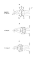
図1(A)、(B)、(C)は本発明の実施例1の接眼レンズの視度が−2.0ディオプター(基準状態)、8.0ディオプター、−10.0ディオプターのときのレンズ断面図である。図2は本発明の実施例1の接眼レンズの基準状態における収差図である。図3(A)、(B)、(C)は本発明の実施例2の接眼レンズの視度が−2.0ディオプター(基準状態)、6.0ディオプター、−8.0ディオプターのときのレンズ断面図である。図4は本発明の実施例2の接眼レンズの基準状態における収差図である。 FIGS. 1A, 1B, and 1C show the case where the diopter of the eyepiece of Example 1 of the present invention is −2.0 diopter (reference state), 8.0 diopter, and −10.0 diopter. It is lens sectional drawing. FIG. 2 is an aberration diagram in the reference state of the eyepiece lens according to the first embodiment of the present invention. FIGS. 3A, 3B and 3C show the case where the diopter of the eyepiece of Example 2 of the present invention is −2.0 diopter (reference state), 6.0 diopter, and −8.0 diopter. It is lens sectional drawing. FIG. 4 is an aberration diagram in the reference state of the eyepiece lens according to the second embodiment of the present invention.
図5(A)、(B)、(C)は本発明の実施例3の接眼レンズの視度が−2.0ディオプター(基準状態)、3.0ディオプター、−6.0ディオプターのときのレンズ断面図である。図6は本発明の実施例3の接眼レンズの基準状態における収差図である。図7は本発明の撮像装置の要部概略図である。 FIGS. 5A, 5B, and 5C illustrate the case where the diopter of the eyepiece of Example 3 of the present invention is −2.0 diopter (reference state), 3.0 diopter, and −6.0 diopter. It is lens sectional drawing. FIG. 6 is an aberration diagram in the reference state of the eyepiece lens according to the third embodiment of the present invention. FIG. 7 is a schematic view of the main part of the imaging apparatus of the present invention.
各実施例の接眼レンズは、デジタルカメラやビデオカメラ等の撮像装置の電子ビューファインダーに用いることができる。レンズ断面図において左方は画像表示面側(物体側)、右方は観察側(アイポイント側)である。レンズ断面図においてLは接眼レンズである。Coは液晶又は有機EL等よりなる画像表示素子である。Iは画像表示素子C0の画像表示素子面である。接眼レンズLは正の屈折力の第1レンズG1、負の屈折力の第2レンズG2、正の屈折力の第3レンズG3よりなっている。EPは観察のためのアイポイント(射出瞳)である。 The eyepiece of each embodiment can be used for an electronic viewfinder of an imaging apparatus such as a digital camera or a video camera. In the lens cross-sectional view, the left side is the image display surface side (object side), and the right side is the observation side (eye point side). In the lens cross-sectional view, L is an eyepiece. Co is an image display element made of liquid crystal or organic EL. I is an image display element surface of the image display element C0. The eyepiece lens L includes a first lens G1 having a positive refractive power, a second lens G2 having a negative refractive power, and a third lens G3 having a positive refractive power. EP is an eye point (exit pupil) for observation.
なお、画像表示面Iから第1レンズG1のレンズ面R1aまでの間や接眼レンズLとアイポイントEPの間に、画像表示面やレンズを保護するプレート等を設けても良い。また、アイポイントEPは画像表示面Iからの最周辺からの光線が観測者の瞳を通過する範囲内であれば光軸方向に前後に移動しても良い。 A plate or the like for protecting the image display surface or the lens may be provided between the image display surface I and the lens surface R1a of the first lens G1 or between the eyepiece lens L and the eye point EP. Further, the eye point EP may be moved back and forth in the optical axis direction as long as the light rays from the outermost periphery from the image display surface I pass through the observer's pupil.
各収差図においてはファインダー視度が基準状態のときを示している。球面収差図において、実線のdはd線(波長587.6nm)、二点鎖線のgはg線(波長435.8nm)を示す。非点収差図において実線のSはd線のサジタル像面、点線のMはd線のメリディオナル像面を示す。倍率色収差はg線について示している。 In each aberration diagram, the viewfinder diopter is in a reference state. In the spherical aberration diagram, the solid line d indicates the d line (wavelength 587.6 nm), and the two-dot chain line g indicates the g line (wavelength 435.8 nm). In the astigmatism diagram, the solid line S represents the d-line sagittal image plane, and the dotted line M represents the d-line meridional image plane. The lateral chromatic aberration is shown for the g-line.
各実施例の接眼レンズLは、画像表示面I側(物体側)から観察側(アイポイント側)EPに向かって順に、正の屈折力の第1レンズG1、負の屈折力の第2レンズG2、正の屈折力の第3レンズG3より構成されている。 The eyepiece lens L of each embodiment includes a first lens G1 having a positive refractive power and a second lens having a negative refractive power in order from the image display surface I side (object side) to the observation side (eyepoint side) EP. G2 includes a third lens G3 having a positive refractive power.
各実施例の接眼レンズLでは、第1レンズG1の画像表示面I側のレンズ面R1aに正の屈折力を持たせ、接眼レンズL全系の画像表示面I側の主点位置を画像表示面I側によせて、画像表示面Iから第1レンズG1までの間隔を長くしている。また、これ以降の観察側のレンズ面での光線高さ(光軸からの距離)を低くし、第1レンズG1の観察側のレンズ面以降でのコマ収差の発生量を抑制している。 In the eyepiece lens L of each embodiment, the lens surface R1a on the image display surface I side of the first lens G1 has a positive refractive power, and the main point position on the image display surface I side of the entire eyepiece lens L system is displayed as an image. The distance from the image display surface I to the first lens G1 is increased on the surface I side. Further, the light ray height (distance from the optical axis) on the subsequent lens surface on the observation side is lowered, and the amount of coma aberration generated on and after the lens surface on the observation side of the first lens G1 is suppressed.
更に、第2レンズG2の観察側のレンズ面R2bの曲率半径をレンズ面R1aの曲率半径に近い凹形状とすることでコマ収差の補正を良好に行っている。また、レンズ面R1aとレンズ面R2bをそれぞれ非球面形状とすることで、レンズ周辺より発生する高次収差を軽減している。 Further, the coma is corrected well by making the radius of curvature of the lens surface R2b on the observation side of the second lens G2 a concave shape close to the radius of curvature of the lens surface R1a. Further, the lens surface R1a and the lens surface R2b are each aspherical to reduce high-order aberrations generated from the lens periphery.
次に、各実施例の接眼レンズLでは、視度調整を第1レンズG1から第3レンズG3までの全てのレンズを一体的に(相対的な位置関係を変えずに)光軸方向に移動させて行ない、これにより視度変化によるコマ収差の変動を軽減している。尚、視度調整は、必ずしも3つのレンズを一体的に移動させる必要は無く、第1レンズG1から第3レンズG3までのうちの1つ又は2つのレンズを移動させても良く、又は他のレンズとは異なる移動量で移動させて行っても良い。 Next, in the eyepiece lens L of each embodiment, all the lenses from the first lens G1 to the third lens G3 are moved in the direction of the optical axis in an integrated manner (without changing the relative positional relationship). This reduces the fluctuation of coma due to diopter change. Note that diopter adjustment does not necessarily require the three lenses to move integrally, and one or two of the first lens G1 to the third lens G3 may be moved, or other The movement may be performed with a movement amount different from that of the lens.
各実施例の接眼レンズにおいて、第1レンズG1の画像表示面I側のレンズ面R1aは画像表示面I側に凸形状であり、第2レンズG2の観察側のレンズ面R2bは観察側に凹形状である。接眼レンズLの焦点距離をf、レンズ面R1aの焦点距離をf11、レンズ面R2bの焦点距離をf22とする。このとき、
0.65<f11/f<1.00 ・・・(1)
−0.75<f22/f<−0.30 ・・・(2)
なる条件式を満たしている。
In the eyepiece of each embodiment, the lens surface R1a on the image display surface I side of the first lens G1 is convex on the image display surface I side, and the lens surface R2b on the observation side of the second lens G2 is concave on the observation side. Shape. The focal length of the eyepiece lens L is f, the focal length of the lens surface R1a is f11, and the focal length of the lens surface R2b is f22. At this time,
0.65 <f11 / f <1.00 (1)
−0.75 <f22 / f <−0.30 (2)
The following conditional expression is satisfied.
ここでレンズ面の焦点距離frはレンズ面の曲率半径をR、レンズ面の入射側と出射側の媒質の屈折率を各々N、N’とするとき、
fr=R/(N’−N)
である。次に前述の各条件式の技術的意味について説明する。
Here, the focal length fr of the lens surface is R when the radius of curvature of the lens surface is N, and the refractive indices of the medium on the entrance side and the exit side of the lens surface are N and N ′, respectively.
fr = R / (N′−N)
It is. Next, the technical meaning of each conditional expression will be described.
条件式(1)は接眼レンズ全系の焦点距離に対するレンズ面R1aの焦点距離の比を規定している。条件式(1)の上限値を超えると、反射型の画像表示素子Coを配する空間が少なくなり、画像表示素子Coの配置が困難となり、使用可能な画像表示素子Coが限定されてくる。逆に下限値を超えると、コマ収差、非点収差及び高次収差が増大してくる。 Conditional expression (1) defines the ratio of the focal length of the lens surface R1a to the focal length of the whole eyepiece lens system. When the upper limit value of conditional expression (1) is exceeded, the space for arranging the reflective image display element Co is reduced, it becomes difficult to arrange the image display element Co, and usable image display elements Co are limited. Conversely, when the lower limit is exceeded, coma, astigmatism, and higher-order aberrations increase.
条件式(2)は接眼レンズ全系の焦点距離に対するレンズ面R2bの焦点距離の比を規定している。条件式(2)の上限値を超えると、コマ収差、非点収差及び高次収差が増大してくる。逆に下限値を超えると、反射型の画像表示素子Coを配する空間が少なくなり、画像表示素子の配置が困難となり、使用可能な画像表示素子Coが限定されてくる。更に好ましくは条件式(1)、(2)の数値範囲を次の如く設定するのが良い。
0.75<f11/f<0.98 ・・・(1a)
−0.745<f22/f<−0.400 ・・・(2a)
Conditional expression (2) defines the ratio of the focal length of the lens surface R2b to the focal length of the whole eyepiece lens system. When the upper limit of conditional expression (2) is exceeded, coma, astigmatism and higher order aberrations increase. On the contrary, when the lower limit is exceeded, the space for arranging the reflective image display element Co is reduced, it becomes difficult to arrange the image display elements, and the usable image display elements Co are limited. More preferably, the numerical ranges of conditional expressions (1) and (2) are set as follows.
0.75 <f11 / f <0.98 (1a)
-0.745 <f22 / f <-0.400 (2a)
以上の如く構成することにより、画像表示面Iから第1レンズG1までの間隔を長くしながら、拡大率および見かけ視界が大きく、画像表示面Iに表示された画像を良好に観測出来る接眼レンズが得られる。各実施例において更に好ましくは次の条件式のうち1以上を満足するのが良い。 By configuring as described above, an eyepiece lens that has a large magnification ratio and a large apparent field of view and can observe an image displayed on the image display surface I satisfactorily while increasing the distance from the image display surface I to the first lens G1. can get. In each embodiment, it is more preferable to satisfy one or more of the following conditional expressions.
レンズ面R1aは有効径がDR11で非球面形状であり、レンズ面R1aのレンズ面頂点からレンズ面R1aの有効径の位置までの光軸方向の長さをLpとする。レンズ面R2bは有効径がDR22で非球面形状であり、レンズ面R2bのレンズ面頂点からレンズ面R2bの有効径の位置までの光軸方向の長さをLnとする。 The lens surface R1a has an effective diameter of DR11 and is aspherical, and the length in the optical axis direction from the lens surface vertex of the lens surface R1a to the position of the effective diameter of the lens surface R1a is Lp. The lens surface R2b has an effective diameter of DR22 and is aspherical, and the length in the optical axis direction from the lens surface vertex of the lens surface R2b to the position of the effective diameter of the lens surface R2b is Ln.
このとき、
0.18<Lp/DR11<0.25 ・・・(3)
0.80<(Lp/DR11)/(Ln/DR22)<1.10 ・・・(4)
なる条件式のうち1以上を満足するのが良い。次に前述した各条件式の技術的意味について説明する。
At this time,
0.18 <Lp / DR11 <0.25 (3)
0.80 <(Lp / DR11) / (Ln / DR22) <1.10 (4)
It is preferable to satisfy one or more of the following conditional expressions. Next, the technical meaning of each conditional expression described above will be described.
条件式(3)はレンズ面R1aの有効径に対するレンズ面R1aの曲率の深さを規定している。条件式(3)の上限値を超えると、コマ収差、非点収差及び高次収差が増大してくる。逆に下限値を超えると、反射型の画像表示素子Coを配する空間が少なくなり、画像表示素子Coの配置が困難となり、使用可能な画像表示素子Coが限定されてくる。 Conditional expression (3) defines the depth of curvature of the lens surface R1a with respect to the effective diameter of the lens surface R1a. If the upper limit value of conditional expression (3) is exceeded, coma, astigmatism and higher order aberrations will increase. On the contrary, if the lower limit is exceeded, the space for arranging the reflective image display element Co is reduced, the arrangement of the image display element Co becomes difficult, and the usable image display elements Co are limited.
条件式(4)はレンズ面R1aの有効径に対するレンズ面R1aの曲率の深さの比とレンズ面R2bの有効径に対するレンズ面R2bの曲率の深さの比を規定している。条件式(4)の上限値又は下限値を超えると、コマ収差、非点収差及び高次収差が増大してくる。条件式(4)の範囲内であれば、レンズ面R1aとレンズ面R2bの各レンズ面で発生するコマ収差が互いに打ち消し合い良好な光学性能を保持することができる。更に好ましくは条件式(3)、(4)の数値範囲を次の如く設定するのが良い。
0.190<Lp/DR11<0.245 ・・・(3a)
0.85<(Lp/DR11)/(Ln/DR22)<1.00 ・・・(4a)
Conditional expression (4) defines the ratio of the curvature depth of the lens surface R1a to the effective diameter of the lens surface R1a and the ratio of the curvature depth of the lens surface R2b to the effective diameter of the lens surface R2b. When the upper limit value or lower limit value of conditional expression (4) is exceeded, coma aberration, astigmatism, and higher-order aberration increase. If it is within the range of conditional expression (4), coma aberration generated on the lens surfaces R1a and R2b cancels each other and good optical performance can be maintained. More preferably, the numerical ranges of conditional expressions (3) and (4) should be set as follows.
0.190 <Lp / DR11 <0.245 (3a)
0.85 <(Lp / DR11) / (Ln / DR22) <1.00 (4a)
以上のように、各実施例によれば、画像表示面Iと接眼レンズLの小型化を図りつつ、画像を大きく、且つ、画質を良好に観測することができる接眼レンズが得られる。 As described above, according to each embodiment, it is possible to obtain an eyepiece that can reduce the size of the image display surface I and the eyepiece L, and that can observe an image with a large size and good image quality.
また、次の条件式のうち、1以上を満足するのが良い。
−100.00<(r2b+r1a)/(r2b−r1a)<−5.00 ・・・(5)
0.30<(r1b+r1a)/(r1b−r1a)<1.50 ・・・(6)
Moreover, it is preferable to satisfy one or more of the following conditional expressions.
−100.00 <(r2b + r1a) / (r2b−r1a) <− 5.00 (5)
0.30 <(r1b + r1a) / (r1b−r1a) <1.50 (6)
このとき、第1レンズG1の画像表示面I側のレンズ面R1aの曲率半径(近軸の曲率半径)をr1a、第1レンズG1の観察側のレンズ面の曲率半径(近軸の曲率半径)をr1b、第2レンズG2の観察側のレンズ面R2bの曲率半径(近軸の曲率半径)をr2bとする。 At this time, the radius of curvature of the lens surface R1a on the image display surface I side of the first lens G1 (paraxial radius of curvature) is r1a, and the radius of curvature of the lens surface on the observation side of the first lens G1 (paraxial radius of curvature). R1b, and the radius of curvature (paraxial radius of curvature) of the lens surface R2b on the observation side of the second lens G2 is r2b.
条件式(5)は、第1レンズG1の画像表示面I側のレンズ面R1aと第2レンズG2の観察側のレンズ面R2bのシェープファクターを規定する条件式である。条件式(5)を満足することにより、第1レンズG1の画像表示面I側のレンズ面R1a及び第2レンズG2の観察側のレンズ面R2bで発生するコマ収差や非点収差、高次収差を効果的にキャンセルさせることができる。 Conditional expression (5) is a conditional expression that defines the shape factor of the lens surface R1a on the image display surface I side of the first lens G1 and the lens surface R2b on the observation side of the second lens G2. By satisfying conditional expression (5), coma aberration, astigmatism, and higher-order aberration generated on the lens surface R1a on the image display surface I side of the first lens G1 and the lens surface R2b on the observation side of the second lens G2. Can be canceled effectively.
条件式(5)の上限値を超えると、レンズ面R1aの曲率半径とレンズ面R2bの曲率半径の差が大きくなり過ぎて、コマ収差や非点収差、高次収差を十分に補正することが困難になるため好ましくない。 If the upper limit of conditional expression (5) is exceeded, the difference between the radius of curvature of the lens surface R1a and the radius of curvature of the lens surface R2b becomes too large, and coma, astigmatism, and higher-order aberrations can be sufficiently corrected. Since it becomes difficult, it is not preferable.
条件式(5)の下限値を超えると、レンズ面R1aの曲率半径に対してレンズ面R2bの曲率半径が大きくなり過ぎて、コマ収差や非点収差、高次収差をキャンセルさせる効果が小さくなるため好ましくない。 When the lower limit of conditional expression (5) is exceeded, the radius of curvature of the lens surface R2b becomes too large with respect to the radius of curvature of the lens surface R1a, and the effect of canceling coma aberration, astigmatism, and higher-order aberration is reduced. Therefore, it is not preferable.
条件式(6)は、第1レンズG1の画像表示面I側のレンズ面R1aと第1レンズG1の観察側のレンズ面のシェープファクターを規定する条件式である。条件式(6)の上限値を超えると、画像表示面I側の主点位置が観察側へ移動し、反射型の画像表示素子Coを配する空間が少なくなり、画像表示素子の配置が困難となる。その結果、使用可能な画像表示素子Coが限定されてしまうため、好ましくない。 Conditional expression (6) is a conditional expression that defines the shape factor of the lens surface R1a on the image display surface I side of the first lens G1 and the lens surface on the observation side of the first lens G1. If the upper limit value of conditional expression (6) is exceeded, the principal point position on the image display surface I side moves to the observation side, the space for arranging the reflective image display element Co is reduced, and it is difficult to arrange the image display element. It becomes. As a result, usable image display elements Co are limited, which is not preferable.
条件式(6)の下限値を超えると、コマ収差、非点収差及び高次収差が多く発生するため好ましくない。 Exceeding the lower limit of conditional expression (6) is not preferable because many coma, astigmatism, and higher-order aberrations occur.
なお、好ましくは条件式(5)、(6)の数値範囲を以下のように設定するのがよい。
−57.70<(r2b+r1a)/(r2b−r1a)<−9.27 ・・・(5a)
0.59<(r1b+r1a)/(r1b−r1a)<1.07 ・・・(6a)
Preferably, the numerical ranges of conditional expressions (5) and (6) are set as follows.
−57.70 <(r2b + r1a) / (r2b−r1a) <− 9.27 (5a)
0.59 <(r1b + r1a) / (r1b−r1a) <1.07 (6a)
また各実施例の接眼レンズLを、画像を表示する画像表示素子Coと、画像表示素子Coの画像表示面Iに表示される画像を観察する観察装置に用いるときには次の条件式のうち1以上を満足するのが良い。画像表示面Iの対角長の半値をHとする。視度が0ディオプターのときの画像表示面Iから第1レンズG1のレンズ面R1aまでの空気換算距離をLとする。このとき、次の条件式のうち1以上を満足するのが良い。
0.15<H/f<0.30 ・・・(7)
0.70<L/f<0.80 ・・・(8)
When the eyepiece L of each embodiment is used for an image display element Co for displaying an image and an observation apparatus for observing an image displayed on the image display surface I of the image display element Co, one or more of the following conditional expressions: Good to be satisfied. H is the half value of the diagonal length of the image display surface I. Let L be the air equivalent distance from the image display surface I to the lens surface R1a of the first lens G1 when the diopter is 0 diopter. At this time, it is preferable to satisfy one or more of the following conditional expressions.
0.15 <H / f <0.30 (7)
0.70 <L / f <0.80 (8)
次に前述した各条件式の技術的意味について説明する。 Next, the technical meaning of each conditional expression described above will be described.
条件式(7)は接眼レンズL全系の焦点距離に対する画像表示素子Coの対角線長の比を規定している。条件式(7)の上限値を超えると、反射型の画像表示素子Coを配する空間が少なくなり画像表示素子Coの配置が困難となり、使用可能な画像表示素子Coが限定されてくる。逆に下限値を超えると、接眼レンズLの光学全長(第1レンズ面から最終レンズ面までの長さ)が長くなってくる。 Conditional expression (7) defines the ratio of the diagonal length of the image display element Co to the focal length of the entire eyepiece lens L system. When the upper limit value of conditional expression (7) is exceeded, the space for arranging the reflective image display element Co is reduced, making it difficult to arrange the image display element Co, and the usable image display elements Co are limited. Conversely, when the lower limit is exceeded, the total optical length of the eyepiece lens L (the length from the first lens surface to the final lens surface) becomes longer.
条件式(8)は接眼レンズL全系の焦点距離に対する画像表示面Iから第1レンズG1のレンズ面R1aまでの間隔との比を規定している。条件式(8)の上限値を超えると、コマ収差、非点収差が増大してくる。逆に下限値を超えると、反射型の画像表示素子Coを配する空間が少なくなり、画像表示素子Coの配置が困難となり、使用可能な画像表示素子Coが限定されてくる。更に好ましくは条件式(7)、(8)の数値範囲を次の如く設定するのが良い。
0.16<H/f<0.28 ・・・(7a)
0.72<L/f<0.78 ・・・(8a)
Conditional expression (8) defines the ratio of the distance from the image display surface I to the lens surface R1a of the first lens G1 with respect to the focal length of the entire eyepiece lens L system. If the upper limit value of conditional expression (8) is exceeded, coma and astigmatism will increase. On the contrary, if the lower limit is exceeded, the space for arranging the reflective image display element Co is reduced, the arrangement of the image display element Co becomes difficult, and the usable image display elements Co are limited. More preferably, the numerical ranges of conditional expressions (7) and (8) should be set as follows.
0.16 <H / f <0.28 (7a)
0.72 <L / f <0.78 (8a)
次に本発明の観察装置を有する撮像装置について説明する。 Next, an imaging apparatus having the observation apparatus of the present invention will be described.
本発明の撮像装置は、物体の画像を撮像する撮像素子と、撮像素子によって撮像された物体の像を表示する画像表示素子と、画像表示素子の画像表示面に表示された画像を観察するために用いられる観察装置を有する。 An imaging device of the present invention observes an image displayed on an image display surface of an image display device that displays an image of an object picked up by an image pickup device that picks up an image of an object, an image of the object. It has an observation device used.
次に本発明の撮像装置をビデオカメラを例にとり図7を用いて説明する。図7において、10はビデオカメラ本体(撮像装置本体)、11は、不図示の撮像素子上に被写体像を結ぶ撮影光学系(撮像光学系)、12は集音マイクである。13は本発明の接眼レンズによって不図示の画像表示素子に表示された被写体像を観察するための観察装置(電子ビューファインダー)である。画像表示素子は液晶パネル等によって構成され、撮影光学系11によって形成される物体像等が表示される。この様に本発明の観察装置をビデオカメラ等の撮像装置に適用することにより、物体像を好適に観測することができる。
Next, the image pickup apparatus of the present invention will be described using a video camera as an example with reference to FIG. In FIG. 7,
以下に本発明の各実施例に対応する数値実施例を示す。数値実施例において、画像表示面から観察側へ順に、riは第i番目の面の近軸曲率半径を示し、diは第i番目の面と第i+1番目の面との間の軸上面間隔を示す。さらに、niは第i番目の硝材のd線(波長=578.6nm)に対する屈折率を示し、νiは第i番目の硝材のd線に対するアッベ数を示す。r1は画像表示面、r8はアイポイントEPを示す。 Numerical examples corresponding to the respective embodiments of the present invention will be shown below. In the numerical example, in the order from the image display surface to the observation side, ri indicates the paraxial radius of curvature of the i-th surface, and di indicates the axial upper surface distance between the i-th surface and the i + 1-th surface. Show. Further, ni represents the refractive index of the i-th glass material with respect to the d-line (wavelength = 578.6 nm), and νi represents the Abbe number of the i-th glass material with respect to the d-line. r1 represents an image display surface, and r8 represents an eye point EP.
なお、長さの単位は、特記の無い場合[mm]である。ただし、接眼光学系Lは、比例拡大または比例縮小しても同等の光学性能が得られるので、単位は[mm]に限定されることなく、他の適当な単位を用いることが出来る。なお、各数値実施例において近軸曲率半径の欄に非球面と書かれている面は次の式によって定義される非球面形状である。
x=(h2/R)/[1+[1−(1+k)(h/R)2]1/2]+A4h4+A6h6
なお、xはレンズ面の頂点からの光軸方向の距離、hは光軸に対し垂直な方向の高さ、Rはレンズ面の頂点での近軸の曲率半径、kは円錐定数、A4、A6はそれぞれ多項式係数(非球面係数)である。非球面係数を示す表において、「e−i」は10を底とする指数表現、すなわち「10−i」を表している。又、前述の各条件式と数値実施例における諸数との関係を表1に示す。
The unit of length is [mm] unless otherwise specified. However, since the eyepiece optical system L can obtain the same optical performance even when proportionally enlarged or reduced, the unit is not limited to [mm], and other appropriate units can be used. In each numerical example, the surface written as aspherical in the column of the paraxial radius of curvature is an aspherical shape defined by the following equation.
x = (h 2 / R) / [1+ [1- (1 + k) (h / R) 2 ] 1/2 ] + A4h 4 + A6h 6
X is the distance in the optical axis direction from the apex of the lens surface, h is the height in the direction perpendicular to the optical axis, R is the paraxial radius of curvature at the apex of the lens surface, k is the conic constant, A4, A6 is a polynomial coefficient (aspheric coefficient). In the table showing the aspheric coefficient, “e−i” represents an exponential expression with 10 as the base, that is, “10 −i ”. Table 1 shows the relationship between the above-described conditional expressions and the numbers in the numerical examples.
[数値実施例1]
単位 mm
面データ
面番号 r d nd νd
1 (画像表示面) (可変)
2* 10.477 8.39 1.49171 57.4
3 -49.574 -0.00
4 30.808 1.30 1.63400 23.9
5* 10.085 4.10
6* 26.604 4.73 1.49171 57.4
7* -27.532 (可変)
8 (アイポイント)
非球面データ
第2面
K =-1.85804e+000
第5面
K =-8.27900e-001
第6面
K = 7.03727e-001
第7面
K =-5.84921e+000 A 4=-1.21085e-005 A 6= 1.00489e-007
各種データ
視度[diopter] -2.0 +8.0 -10.0
焦点距離 22.10 22.10 22.10
d 1 15.70 20.46 11.01
d 7 19.40 14.64 24.09
[Numerical Example 1]
Unit mm
Surface data surface number rd nd νd
1 (Image display surface) (Variable)
2 * 10.477 8.39 1.49171 57.4
3 -49.574 -0.00
4 30.808 1.30 1.63400 23.9
5 * 10.085 4.10
6 * 26.604 4.73 1.49171 57.4
7 * -27.532 (variable)
8 (Eyepoint)
Aspheric data 2nd surface
K = -1.85804e + 000
5th page
K = -8.27900e-001
6th page
K = 7.03727e-001
7th page
K = -5.84921e + 000 A 4 = -1.21085e-005 A 6 = 1.00489e-007
Various data diopters [diopter] -2.0 +8.0 -10.0
Focal length 22.10 22.10 22.10
d 1 15.70 20.46 11.01
d 7 19.40 14.64 24.09
[数値実施例2]
単位 mm
面データ
面番号 r d nd νd
1 (画像表示面) (可変)
2* 11.055 7.09 1.49171 57.4
3 -91.313 -0.00
4 30.065 2.60 1.63400 23.9
5* 9.983 4.80
6* 26.321 6.95 1.49171 57.4
7* -28.790 19.00
8 (アイポイント)
非球面データ
第2面
K =-1.75305e+000
第5面
K =-9.09128e-001
第6面
K =-7.46404e-001
第7面
K = 8.51859e-001 A 4= 1.64082e-005 A 6= 3.05569e-008
各種データ
視度[diopter] -2.0 +6.0 -8.0
焦点距離 25.00 25.00 25.00
d 1 17.36 22.20 13.27
[Numerical Example 2]
Unit mm
Surface data surface number rd nd νd
1 (Image display surface) (Variable)
2 * 11.055 7.09 1.49171 57.4
3 -91.313 -0.00
4 30.065 2.60 1.63400 23.9
5 * 9.983 4.80
6 * 26.321 6.95 1.49171 57.4
7 * -28.790 19.00
8 (Eyepoint)
Aspheric data 2nd surface
K = -1.75305e + 000
5th page
K = -9.09128e-001
6th page
K = -7.46404e-001
7th page
K = 8.51859e-001 A 4 = 1.64082e-005 A 6 = 3.05569e-008
Various data diopters [diopter] -2.0 +6.0 -8.0
Focal length 25.00 25.00 25.00
d 1 17.36 22.20 13.27
[数値実施例3]
単位 mm
面データ
面番号 r d nd νd
1 (画像表示面) (可変)
2* 12.593 5.47 1.49171 57.4
3 -1030.662 -0.00
4 29.335 4.04 1.63400 23.9
5* 10.365 5.00
6* 27.418 10.00 1.49171 57.4
7* -30.747 19.40
8 (アイポイント)
非球面データ
第2面
K =-1.60310e+000
第5面
K =-8.65443e-001
第6面
K =-1.43041e+000
第7面
K =-1.87051e+000 A 4=-5.88084e-006 A 6=-1.53534e-008
各種データ
視度[diopter] -2.0 +3.0 -6.0
焦点距離 30.00 30.00 30.00
d 1 20.66 25.14 16.90
[Numerical Example 3]
Unit mm
Surface data surface number rd nd νd
1 (Image display surface) (Variable)
2 * 12.593 5.47 1.49171 57.4
3 -1030.662 -0.00
4 29.335 4.04 1.63400 23.9
5 * 10.365 5.00
6 * 27.418 10.00 1.49 171 57.4
7 * -30.747 19.40
8 (Eyepoint)
Aspheric data 2nd surface
K = -1.60310e + 000
5th page
K = -8.65443e-001
6th page
K = -1.43041e + 000
7th page
K = -1.87051e + 000 A 4 = -5.88084e-006 A 6 = -1.53534e-008
Various data diopters [diopter] -2.0 +3.0 -6.0
Focal length 30.00 30.00 30.00
d 1 20.66 25.14 16.90

L 接眼レンズ
G1 第1レンズ
G2 第2レンズ
G3 第3レンズ
I 画像表示面
EP アイポイント
L eyepiece G1 first lens G2 second lens G3 third lens I image display surface EP eyepoint
Claims (10)
前記第1レンズの物体側のレンズ面R1aは物体側に凸形状であり、前記第2レンズの観察側のレンズ面R2bは観察側に凹形状であり、
前記接眼レンズの焦点距離をf、前記レンズ面R1aの焦点距離をf11、前記レンズ面R2bの焦点距離をf22、前記レンズ面R1aの曲率半径をr1a、前記レンズ面R2bの曲率半径をr2bとするとき、
0.65<f11/f<1.00
−0.75<f22/f<−0.30
−100.00<(r2b+r1a)/(r2b−r1a)<−9.27
なる条件式を満たすことを特徴とする接眼レンズ。 An eyepiece composed of a first lens having a positive refractive power, a second lens having a negative refractive power, and a third lens having a positive refractive power in order from the object side to the observation side,
The object-side lens surface R1a of the first lens is convex on the object side, and the observation-side lens surface R2b of the second lens is concave on the observation side,
The focal length of the eyepiece lens is f, the focal length of the lens surface R1a is f11, the focal length of the lens surface R2b is f22, the radius of curvature of the lens surface R1a is r1a, and the radius of curvature of the lens surface R2b is r2b. When
0.65 <f11 / f <1.00
−0.75 <f22 / f <−0.30
−100.00 <(r2b + r1a) / (r2b−r1a) <− 9.27
An eyepiece that satisfies the following conditional expression:
0.18<Lp/DR11<0.25
なる条件式を満足することを特徴とする請求項1に記載の接眼レンズ。 The lens surface R1a has an aspherical shape, and when the effective diameter of the lens surface R1a is DR11 and the length in the optical axis direction from the lens surface vertex of the lens surface R1a to the position of the effective diameter is Lp,
0.18 <Lp / DR11 <0.25
The eyepiece according to claim 1, wherein the following conditional expression is satisfied.
前記第1レンズの物体側のレンズ面R1aは物体側に凸形状の非球面であり、前記第2レンズの観察側のレンズ面R2bは観察側に凹形状であり、The object-side lens surface R1a of the first lens is a convex aspheric surface on the object side, and the observation-side lens surface R2b of the second lens is concave on the observation side,
前記接眼レンズの焦点距離をf、前記レンズ面R1aの焦点距離をf11、前記レンズ面R2bの焦点距離をf22、前記レンズ面R1aの曲率半径をr1a、前記レンズ面R2bの曲率半径をr2b、前記レンズ面R1aの有効径をDR11、前記レンズ面R1aのレンズ面頂点から有効径の位置までの光軸方向の長さをLpとするとき、The focal length of the eyepiece lens is f, the focal length of the lens surface R1a is f11, the focal length of the lens surface R2b is f22, the radius of curvature of the lens surface R1a is r1a, the radius of curvature of the lens surface R2b is r2b, When the effective diameter of the lens surface R1a is DR11, and the length in the optical axis direction from the lens surface vertex of the lens surface R1a to the position of the effective diameter is Lp,
0.65<f11/f<1.000.65 <f11 / f <1.00
−0.75<f22/f<−0.30−0.75 <f22 / f <−0.30
−100.00<(r2b+r1a)/(r2b−r1a)<−5.00−100.00 <(r2b + r1a) / (r2b−r1a) <− 5.00
0.18<Lp/DR11<0.250.18 <Lp / DR11 <0.25
なる条件式を満たすことを特徴とする接眼レンズ。An eyepiece that satisfies the following conditional expression:
0.80<(Lp/DR11)/(Ln/DR22)<1.10
なる条件式を満足することを特徴とする請求項1乃至3のいずれか1項に記載の接眼レンズ。 The lens surface R1a and the lens surface R2b are aspherical, the effective diameter of the lens surface R1a is DR11, and the length in the optical axis direction from the apex of the lens surface R1a to the position of the effective diameter is Lp, When the effective diameter of the lens surface R2b is DR22, and the length in the optical axis direction from the lens surface vertex of the lens surface R2b to the position of the effective diameter is Ln,
0.80 <(Lp / DR11) / (Ln / DR22) <1.10
Ocular lens according to any one of claims 1 to 3, characterized by satisfying the conditional expression.
0.30<(r1b+r1a)/(r1b−r1a)<1.50
なる条件式を満足することを特徴とする請求項1乃至4のいずれか1項に記載の接眼レンズ。 When the radius of curvature of the lens surface on the observation side of the first lens is r1b,
0.30 <(r1b + r1a) / (r1b−r1a) <1.50
The eyepiece according to any one of claims 1 to 4 , wherein the following conditional expression is satisfied.
0.15<H/f<0.30
なる条件式を満足することを特徴とする請求項7に記載の観察装置。 When the half value of the diagonal length of the image display surface is H,
0.15 <H / f <0.30
The observation apparatus according to claim 7 , wherein the following conditional expression is satisfied.
0.70<L/f<0.80
なる条件式を満足することを特徴とする請求項7または8に記載の観察装置。 When the air equivalent distance from the image display surface to the lens surface R1a when the diopter is 0 diopter is L,
0.70 <L / f <0.80
Observation apparatus according to claim 7 or 8, characterized in that to satisfy the condition.
Priority Applications (5)
| Application Number | Priority Date | Filing Date | Title |
|---|---|---|---|
| JP2014140029A JP6436661B2 (en) | 2013-09-09 | 2014-07-07 | Eyepiece and observation apparatus having the same |
| RU2014135730/28A RU2601244C2 (en) | 2013-09-09 | 2014-09-02 | Eyepiece and viewing device, having eyepiece |
| CN201410444653.9A CN104423030B (en) | 2013-09-09 | 2014-09-03 | Eyepiece lens and observation apparatus having the same |
| EP14183511.6A EP2848975B1 (en) | 2013-09-09 | 2014-09-04 | Eyepiece lens and observation apparatus having the same |
| US14/477,303 US9551864B2 (en) | 2013-09-09 | 2014-09-04 | Eyepiece lens and observation apparatus having the same |
Applications Claiming Priority (3)
| Application Number | Priority Date | Filing Date | Title |
|---|---|---|---|
| JP2013186065 | 2013-09-09 | ||
| JP2013186065 | 2013-09-09 | ||
| JP2014140029A JP6436661B2 (en) | 2013-09-09 | 2014-07-07 | Eyepiece and observation apparatus having the same |
Publications (3)
| Publication Number | Publication Date |
|---|---|
| JP2015072452A JP2015072452A (en) | 2015-04-16 |
| JP2015072452A5 JP2015072452A5 (en) | 2017-08-10 |
| JP6436661B2 true JP6436661B2 (en) | 2018-12-12 |
Family
ID=51483290
Family Applications (1)
| Application Number | Title | Priority Date | Filing Date |
|---|---|---|---|
| JP2014140029A Active JP6436661B2 (en) | 2013-09-09 | 2014-07-07 | Eyepiece and observation apparatus having the same |
Country Status (5)
| Country | Link |
|---|---|
| US (1) | US9551864B2 (en) |
| EP (1) | EP2848975B1 (en) |
| JP (1) | JP6436661B2 (en) |
| CN (1) | CN104423030B (en) |
| RU (1) | RU2601244C2 (en) |
Families Citing this family (2)
| Publication number | Priority date | Publication date | Assignee | Title |
|---|---|---|---|---|
| TWI740493B (en) * | 2020-05-11 | 2021-09-21 | 大陸商信泰光學(深圳)有限公司 | Optical camera lens |
| WO2022141408A1 (en) * | 2020-12-31 | 2022-07-07 | 深圳纳德光学有限公司 | Diopter-adjustable eyepiece optical system and head-mounted display device |
Family Cites Families (21)
| Publication number | Priority date | Publication date | Assignee | Title |
|---|---|---|---|---|
| US2699700A (en) * | 1950-04-11 | 1955-01-18 | Schneider Co Optische Werke | View finder system with adjustable magnification |
| US3141921A (en) * | 1959-12-14 | 1964-07-21 | Bell & Howell Co | Zoom viewfinder with front diaphragm mask |
| JPS57201214A (en) * | 1981-06-04 | 1982-12-09 | Canon Inc | Diopter adjustable finder optical system |
| SU1714563A1 (en) * | 1990-04-02 | 1992-02-23 | Ленинградский Институт Точной Механики И Оптики | Microscope ocular |
| JP2966080B2 (en) * | 1990-10-18 | 1999-10-25 | オリンパス光学工業株式会社 | Pre-aperture triplet lens |
| US5749008A (en) * | 1996-01-18 | 1998-05-05 | Minolta | Eyepiece |
| JP3485503B2 (en) * | 1999-09-09 | 2004-01-13 | 株式会社エンプラス | Imaging lens |
| US6424468B1 (en) * | 2000-09-05 | 2002-07-23 | Nikon Corporation | Eyepiece lens |
| JP4703827B2 (en) * | 2000-09-06 | 2011-06-15 | 株式会社ニコン | Eyepiece optical system |
| JP3749128B2 (en) * | 2001-01-24 | 2006-02-22 | 株式会社エンプラス | Imaging lens |
| JP3749130B2 (en) * | 2001-02-15 | 2006-02-22 | 株式会社エンプラス | Imaging lens |
| JP2002341259A (en) * | 2001-05-18 | 2002-11-27 | Asahi Optical Co Ltd | Ocular for endoscope |
| US6785054B1 (en) * | 2003-02-24 | 2004-08-31 | Eastman Kodak Company | Optical magnifier suitable for use with a microdisplay device |
| JP4646589B2 (en) | 2004-07-29 | 2011-03-09 | オリンパス株式会社 | Viewfinder optical system for single-lens reflex cameras |
| JP2006251412A (en) * | 2005-03-11 | 2006-09-21 | Nidec Copal Corp | Lens for observation |
| JP4817758B2 (en) * | 2005-08-26 | 2011-11-16 | キヤノン株式会社 | Eyepiece optical system and viewfinder system using the same |
| JP4626825B2 (en) * | 2007-05-21 | 2011-02-09 | ソニー株式会社 | Live view optical system and imaging apparatus |
| JP2010266776A (en) * | 2009-05-18 | 2010-11-25 | Olympus Imaging Corp | Eyepiece optical system and electronic view finder using the same |
| JP5587017B2 (en) * | 2010-04-05 | 2014-09-10 | キヤノン株式会社 | Viewfinder eyepiece |
| CN201740920U (en) * | 2010-07-15 | 2011-02-09 | 深圳航天科技创新研究院 | Eye piece |
| JP5591027B2 (en) * | 2010-08-23 | 2014-09-17 | オリンパスイメージング株式会社 | Electronic viewfinder |
-
2014
- 2014-07-07 JP JP2014140029A patent/JP6436661B2/en active Active
- 2014-09-02 RU RU2014135730/28A patent/RU2601244C2/en active
- 2014-09-03 CN CN201410444653.9A patent/CN104423030B/en active Active
- 2014-09-04 EP EP14183511.6A patent/EP2848975B1/en active Active
- 2014-09-04 US US14/477,303 patent/US9551864B2/en active Active
Also Published As
| Publication number | Publication date |
|---|---|
| EP2848975B1 (en) | 2019-05-08 |
| CN104423030A (en) | 2015-03-18 |
| US9551864B2 (en) | 2017-01-24 |
| US20150070777A1 (en) | 2015-03-12 |
| EP2848975A1 (en) | 2015-03-18 |
| RU2014135730A (en) | 2016-03-27 |
| RU2601244C2 (en) | 2016-10-27 |
| JP2015072452A (en) | 2015-04-16 |
| CN104423030B (en) | 2017-01-11 |
Similar Documents
| Publication | Publication Date | Title |
|---|---|---|
| JP6098838B2 (en) | Eyepiece optical system and imaging apparatus | |
| JP2016001209A (en) | Eyepiece and imaging apparatus | |
| JP6257171B2 (en) | Eyepiece optical system and imaging apparatus having the same | |
| JP6615068B2 (en) | Eyepiece and imaging device | |
| JP6060808B2 (en) | Eyepiece optics | |
| JP2016224238A (en) | Eyepiece lens, optical device including eyepiece and eyepiece lens manufacturing method | |
| CN105388608B (en) | Eyepiece and observation device and picture pick-up device including eyepiece | |
| JP6618278B2 (en) | Eyepiece and observation apparatus having the same | |
| JP5587017B2 (en) | Viewfinder eyepiece | |
| JPWO2014041773A1 (en) | Eyepiece and imaging device | |
| JP2018010218A (en) | Eyepiece optical system, optical instrument, and eyepiece optical system manufacturing method | |
| JP5591027B2 (en) | Electronic viewfinder | |
| JP6406929B2 (en) | Eyepiece, observation device having the same, and imaging device | |
| JP2016090828A (en) | Ocular optical system | |
| JP2008008981A (en) | Finder optical system and optical apparatus with the same | |
| JP6436661B2 (en) | Eyepiece and observation apparatus having the same | |
| JP6436680B2 (en) | Viewfinder optical system, observation apparatus having the same, and imaging apparatus | |
| JP7118653B2 (en) | Observation device | |
| JP5554598B2 (en) | Viewfinder optical system | |
| JP6391371B2 (en) | Eyepiece, observation device having the same, and imaging device | |
| JP6429538B2 (en) | Eyepiece, observation device having the same, and imaging device | |
| JP2010237430A (en) | Finder optical system of single lens reflex camera | |
| JP6406930B2 (en) | Eyepiece, observation device having the same, and imaging device | |
| JP2020030421A (en) | Ocular lens and image capturing device | |
| JP2003121760A (en) | Eyepiece system |
Legal Events
| Date | Code | Title | Description |
|---|---|---|---|
| A521 | Request for written amendment filed |
Free format text: JAPANESE INTERMEDIATE CODE: A523 Effective date: 20170627 |
|
| A621 | Written request for application examination |
Free format text: JAPANESE INTERMEDIATE CODE: A621 Effective date: 20170627 |
|
| A977 | Report on retrieval |
Free format text: JAPANESE INTERMEDIATE CODE: A971007 Effective date: 20180302 |
|
| A131 | Notification of reasons for refusal |
Free format text: JAPANESE INTERMEDIATE CODE: A131 Effective date: 20180320 |
|
| A521 | Request for written amendment filed |
Free format text: JAPANESE INTERMEDIATE CODE: A523 Effective date: 20180517 |
|
| TRDD | Decision of grant or rejection written | ||
| A01 | Written decision to grant a patent or to grant a registration (utility model) |
Free format text: JAPANESE INTERMEDIATE CODE: A01 Effective date: 20181016 |
|
| A61 | First payment of annual fees (during grant procedure) |
Free format text: JAPANESE INTERMEDIATE CODE: A61 Effective date: 20181113 |
|
| R151 | Written notification of patent or utility model registration |
Ref document number: 6436661 Country of ref document: JP Free format text: JAPANESE INTERMEDIATE CODE: R151 |