JP6435729B2 - Driving device and driving method thereof - Google Patents

Driving device and driving method thereof Download PDF

Info

Publication number
JP6435729B2
JP6435729B2 JP2014185853A JP2014185853A JP6435729B2 JP 6435729 B2 JP6435729 B2 JP 6435729B2 JP 2014185853 A JP2014185853 A JP 2014185853A JP 2014185853 A JP2014185853 A JP 2014185853A JP 6435729 B2 JP6435729 B2 JP 6435729B2
Authority
JP
Japan
Prior art keywords
rotation
thumb
drive device
hand
rotating
Prior art date
Legal status (The legal status is an assumption and is not a legal conclusion. Google has not performed a legal analysis and makes no representation as to the accuracy of the status listed.)
Active
Application number
JP2014185853A
Other languages
Japanese (ja)
Other versions
JP2016055078A5 (en
JP2016055078A (en
Inventor
豊 荒川
豊 荒川
Current Assignee (The listed assignees may be inaccurate. Google has not performed a legal analysis and makes no representation or warranty as to the accuracy of the list.)
Seiko Epson Corp
Original Assignee
Seiko Epson Corp
Priority date (The priority date is an assumption and is not a legal conclusion. Google has not performed a legal analysis and makes no representation as to the accuracy of the date listed.)
Filing date
Publication date
Application filed by Seiko Epson Corp filed Critical Seiko Epson Corp
Priority to JP2014185853A priority Critical patent/JP6435729B2/en
Priority to CN201510543154.XA priority patent/CN105411810A/en
Priority to US14/851,440 priority patent/US10271967B2/en
Publication of JP2016055078A publication Critical patent/JP2016055078A/en
Publication of JP2016055078A5 publication Critical patent/JP2016055078A5/ja
Application granted granted Critical
Publication of JP6435729B2 publication Critical patent/JP6435729B2/en
Active legal-status Critical Current
Anticipated expiration legal-status Critical

Links

Images

Landscapes

  • Rehabilitation Tools (AREA)
  • Prostheses (AREA)

Description

本発明は、駆動装置およびその駆動方法に関する。   The present invention relates to a driving device and a driving method thereof.

特許文献1には、手に装着され、指関節を屈伸(屈曲あるいは伸展)させることによって、指の動作を補助する装着型動作支援装置が開示されている。   Patent Document 1 discloses a wearable movement support device that is attached to a hand and assists the movement of a finger by bending and extending (bending or extending) a finger joint.

特開2011−115248号公報JP 2011-115248 A

しかし、特許文献1に記載された装置は、主に、人差し指の動作を支援することが想定されて構成されたものであり、親指の動きまで考慮されたものではない。そのため、親指の動きを良好に補助することのできる技術が求められている。このような課題は、人に限らず、動物などの生体の関節や、ロボットなど生体以外の関節の動きを補助する場合においても共通する課題である。   However, the apparatus described in Patent Document 1 is mainly configured to support the operation of the index finger, and does not consider the movement of the thumb. Therefore, there is a need for a technique that can favorably assist the movement of the thumb. Such a problem is not limited to humans, and is a common problem even when assisting movement of a joint of a living body such as an animal or a joint other than a living body such as a robot.

本発明は、上述の課題の少なくとも一部を解決するためになされたものであり、以下の形態として実現することが可能である。
本発明の第1の形態は、
手の甲に配置されるベース部材と、
前記手の親指の背側に配置され、前記ベース部材に回動可能に設けられた第1部材と、
を備え、
前記第1部材は、前記手の人差し指中手骨の長手方向に沿った回動軸周りに回動可能であり、
前記第1部材を、前記回動軸周りに回動させる回動部、を備え、
前記回動部は、
圧電体を含む振動板と、
前記振動板が接触して駆動される被駆動部と、を備える
駆動装置である。本発明は以下の形態としても実現することが可能である。
SUMMARY An advantage of some aspects of the invention is to solve at least a part of the problems described above, and the invention can be implemented as the following forms.
The first aspect of the present invention is:
A base member arranged on the back of the hand;
A first member disposed on the back side of the thumb of the hand and rotatably provided on the base member;
With
The first member is rotatable about a rotation axis along the longitudinal direction of the index finger metacarpal of the hand,
A rotation unit that rotates the first member around the rotation axis;
The rotating part is
A diaphragm including a piezoelectric body;
A driven portion that is driven by contact with the diaphragm.
It is a drive device. The present invention can also be realized as the following forms.

(1)本発明の一形態によれば、駆動装置が提供される。この駆動装置は、ベース部材と、前記ベース部材に回動可能に設けられた第1部材と、を備え、前記第1部材は、前記ベース部材を手の甲に配置した場合に、前記手の人差し指中手骨に沿った回動軸周りに回動可能である。このような形態の駆動装置であれば、第1部材によって、親指の腹側が手の平側に向く動きを良好に補助することができる。 (1) According to one form of this invention, a drive device is provided. The drive device includes a base member and a first member rotatably provided on the base member, and the first member is located in the index finger of the hand when the base member is disposed on the back of the hand. It can be rotated around a rotation axis along the hand bone. If it is a drive device of such a form, the movement which the belly side of the thumb faces to the palm side can be favorably assisted by the first member.

(2)上記形態の駆動装置は、前記第1部材を、前記回動軸周りに回動させる回動部を備えてもよい。このような形態であれば、回動部によって第1部材を回動させることにより、親指の腹が手の平側に向く動きを良好に補助することができる。 (2) The drive device according to the aspect described above may include a rotation unit that rotates the first member around the rotation axis. In such a form, the movement of the thumb belly toward the palm side can be favorably assisted by rotating the first member by the rotating portion.

(3)上記形態の駆動装置において、前記回動部は、圧電体を含む振動板と;前記振動板が接触して駆動される被駆動部と、を備えてもよい。このような形態であれば、回動部を小さく構成することができるので、駆動装置を小型化することができる。 (3) In the driving device according to the aspect described above, the rotating unit may include a diaphragm including a piezoelectric body; and a driven unit that is driven by the diaphragm in contact with the diaphragm. With such a configuration, the rotation unit can be configured to be small, so that the drive device can be reduced in size.

(4)上記形態の駆動装置において、前記振動板には突起部が設けられており、前記突起部が前記被駆動部に接触してもよい。このような形態であれば、振動板が被駆動部に接触するのではなく、突起部が被駆動部に接触するため、回動部の耐久性を高めることができる。 (4) In the driving device according to the above aspect, the diaphragm may be provided with a protrusion, and the protrusion may contact the driven part. With such a configuration, the diaphragm does not contact the driven part, but the projection part contacts the driven part, so that the durability of the rotating part can be improved.

(5)上記形態の駆動装置は、前記第1部材と前記手との間に設けられる弾性部材、を備えてもよい。このような形態であれば、第1部材と手とが擦れることを抑制することができるので、第1部材を、回動軸周りにスムーズに回動させることができる。 (5) The drive device according to the above aspect may include an elastic member provided between the first member and the hand. With such a configuration, the first member and the hand can be prevented from rubbing, so that the first member can be smoothly rotated around the rotation axis.

本発明は、駆動装置としての形態以外にも、種々の形態で実現することが可能である。例えば、駆動装置の駆動方法や、関節の動きを補助する関節駆動装置、等の形態で実現することができる。   The present invention can be realized in various forms other than the form as a driving device. For example, it can be realized in the form of a driving method of the driving device, a joint driving device that assists the movement of the joint, and the like.

本発明の一実施形態としての駆動装置の概略構成を示す模式図である。It is a schematic diagram which shows schematic structure of the drive device as one Embodiment of this invention. 駆動装置の詳細な構成を示す図である。It is a figure which shows the detailed structure of a drive device. 第1回動部の概略構成を示す説明図である。It is explanatory drawing which shows schematic structure of a 1st rotation part. 圧電駆動装置の動作原理について示す説明図である。It is explanatory drawing shown about the operation principle of a piezoelectric drive device. 駆動装置に備えられた関節機構の構造を示す図である。It is a figure which shows the structure of the joint mechanism with which the drive device was equipped. 関節機構の回転可能角度を説明するための図である。It is a figure for demonstrating the rotatable angle of a joint mechanism. 図2におけるA矢視図である。It is A arrow line view in FIG. 図7におけるB矢視図である。It is a B arrow line view in FIG. 図8におけるC矢視図である。It is C arrow line view in FIG. 駆動装置の第1の変形例を示す図である。It is a figure which shows the 1st modification of a drive device. 駆動装置の第2の変形例を示す図である。It is a figure which shows the 2nd modification of a drive device. 駆動装置の第3の変形例を示す図である。It is a figure which shows the 3rd modification of a drive device. 駆動装置の第4の変形例を示す図である。It is a figure which shows the 4th modification of a drive device. 駆動装置の第5の変形例を示す図である。It is a figure which shows the 5th modification of a drive device.

A.駆動装置の構造:
図1は、本発明の一実施形態としての駆動装置1の概略構成を示す模式図である。駆動装置1は、例えば、事故や病気などによって指の曲げ伸ばしに支障が生じた人や、握力が低下した人、高齢のために力が弱くなった人等の手に装着されて指の動きを補助するために用いられる。本実施形態の駆動装置1は、特に、手の親指の動きを補助するために用いられる。以下では、駆動装置1が、被装着部としての手に装着された際に、親指の指先側を「先端側」または「前側」と呼び、親指の根元(第3関節付近)側を「後端側」または「後ろ側」と呼ぶ。また、本明細書において、手の「指」とは、指の種類にかかわらず、指先から第3関節までのことをいう。また、「手」には、「指」も含まれる。
A. Drive structure:
FIG. 1 is a schematic diagram showing a schematic configuration of a driving apparatus 1 as an embodiment of the present invention. The drive device 1 is attached to a hand such as a person who has trouble with bending and stretching of a finger due to an accident or illness, a person who has a weak grip, or a person whose strength has weakened due to aging. Used to assist. The drive device 1 of this embodiment is used in particular to assist the movement of the thumb of the hand. In the following, when the drive device 1 is attached to the hand as the attached part, the fingertip side of the thumb is referred to as “front end side” or “front side”, and the base of the thumb (near the third joint) is referred to as “rear side”. Called “end side” or “rear side”. Further, in this specification, the “finger” of the hand means from the fingertip to the third joint regardless of the kind of the finger. “Hand” also includes “finger”.

駆動装置1は、ベース部材10と第1部材20と第2部材30とを備える。ベース部材10は、手の甲側に配置される部材である。ベース部材10は、扁平なブロック状の外形形状を有しており、例えば、バンドやフックなどの任意の固定具によって手に装着される。第1部材20は、手の人差し指中手骨80に沿った第1回動軸51周りに回動可能にベース部材10に設けられている。第1部材20は、親指の背側の第3関節付近から第2関節付近にかけて配置される。第2部材30は、第1部材20に対して相対的に回動可能な部材である。第2部材30の先端部は、親指の背側の第1関節から第2関節までの間に固定される。後述するように、駆動装置1は、ベース部材10と第2部材30との間の距離が変更可能に構成されている。なお、第1部材20が回動する第1回動軸51は、手の人差し指が回動する軸とは異なる方向の軸である。   The drive device 1 includes a base member 10, a first member 20, and a second member 30. The base member 10 is a member disposed on the back side of the hand. The base member 10 has a flat block-like outer shape, and is attached to the hand by an arbitrary fixing tool such as a band or a hook. The first member 20 is provided on the base member 10 so as to be rotatable around the first rotation shaft 51 along the index finger metacarpal 80 of the hand. The first member 20 is arranged from the vicinity of the third joint on the dorsal side of the thumb to the vicinity of the second joint. The second member 30 is a member that can rotate relative to the first member 20. The tip of the second member 30 is fixed between the first joint on the back side of the thumb and the second joint. As will be described later, the driving device 1 is configured such that the distance between the base member 10 and the second member 30 can be changed. The first rotation shaft 51 on which the first member 20 rotates is an axis in a direction different from the axis on which the index finger of the hand rotates.

図2は、駆動装置1の詳細な構成を示す図である。ベース部材10は、第1回動軸51と第1回動部12と制御部14とを備えている。第1回動軸51には、第1部材20が接続される。第1回動部12は、第1回動軸51を駆動することにより、第1部材20を第1回動軸51周りに相対的に回動させる。第1回動部12の詳しい構成については後述する。制御部14は、第1回動部12や、後述する第2回動部118、第3回動部122、第4回動部142を制御して親指の動きを補助するための回路を備えている。制御部14は、ベース部材10以外の部分に備えられていてもよい。   FIG. 2 is a diagram showing a detailed configuration of the driving device 1. The base member 10 includes a first rotation shaft 51, a first rotation unit 12, and a control unit 14. The first member 20 is connected to the first rotation shaft 51. The first rotation unit 12 relatively rotates the first member 20 around the first rotation shaft 51 by driving the first rotation shaft 51. A detailed configuration of the first rotating unit 12 will be described later. The control unit 14 includes a circuit for assisting the movement of the thumb by controlling the first rotation unit 12, a second rotation unit 118, a third rotation unit 122, and a fourth rotation unit 142 described later. ing. The control unit 14 may be provided in a portion other than the base member 10.

第1部材20は、第1連結部110と第2連結部120とを備えている。第1連結部110は、第1副部材112と第2副部材114とを備えている。   The first member 20 includes a first connecting part 110 and a second connecting part 120. The first connecting part 110 includes a first sub member 112 and a second sub member 114.

第1副部材112は、ベース部材10の第1回動軸51周りに回動可能な部材である。第1副部材112は、弾性部材116と、第2回動部118と、第2回動軸52と、を備えている。弾性部材116は、第1副部材112と手の甲との間に配置される。弾性部材116の材料としては、例えば、弾性ゴムやスポンジ、バネを用いることができる。なお、弾性部材116は省略してもよい。   The first sub member 112 is a member that can rotate around the first rotation shaft 51 of the base member 10. The first sub member 112 includes an elastic member 116, a second rotating part 118, and a second rotating shaft 52. The elastic member 116 is disposed between the first sub member 112 and the back of the hand. As a material of the elastic member 116, for example, elastic rubber, sponge, or spring can be used. The elastic member 116 may be omitted.

第2回動部118は、第1副部材112内に設けられており、第2回動軸52を駆動する。第2回動軸52は、駆動装置1が手に装着されたときに、親指の第3関節付近に配置される。第2回動軸52は、親指が第3関節を中心として人差し指に対して開閉する軸に沿っている。第2回動軸52には、第2回動軸52周りに回動可能に第2副部材114の後端部が接続されている。そのため、第2回動部118は、親指が人差し指に対して開閉する方向(第1回動方向)に第2副部材114を駆動することができる。なお、第2回動部118は、第1副部材112の外部に設けられていてもよい。   The second rotating unit 118 is provided in the first sub member 112 and drives the second rotating shaft 52. The second rotation shaft 52 is disposed in the vicinity of the third joint of the thumb when the driving device 1 is attached to the hand. The second rotation shaft 52 is along the axis where the thumb opens and closes with respect to the index finger around the third joint. A rear end portion of the second sub member 114 is connected to the second rotation shaft 52 so as to be rotatable around the second rotation shaft 52. Therefore, the second rotation unit 118 can drive the second sub member 114 in a direction (first rotation direction) in which the thumb opens and closes with respect to the index finger. Note that the second rotating portion 118 may be provided outside the first sub member 112.

第2副部材114は、略直方体状の形状を有している。第2副部材114は、その先端面に開口部115を備えている。開口部115には、第2連結部120の後端部が挿入されている。第2副部材114内には、第2連結部120を前後方向にスライド移動させるための第1スライド機構117が設けられている。本実施形態では、第2連結部120が、第1スライド機構117によって第2副部材114に対して摺動することにより、ベース部材10と第2部材30との間の距離が可変する。   The second sub member 114 has a substantially rectangular parallelepiped shape. The second sub member 114 is provided with an opening 115 at the front end surface thereof. A rear end portion of the second connecting portion 120 is inserted into the opening 115. A first slide mechanism 117 for sliding the second connecting portion 120 in the front-rear direction is provided in the second sub member 114. In the present embodiment, the distance between the base member 10 and the second member 30 varies as the second connecting portion 120 slides with respect to the second sub member 114 by the first slide mechanism 117.

第2連結部120は、略直方体状の形状を有している。第2連結部120は、第3回動部122と第3回動軸53とを備えている。第3回動部122は、第2連結部120内に備えられており、第3回動軸53を駆動する。第3回動軸53は、駆動装置1が手に装着されたときに、親指の第2関節付近に配置される。第3回動軸53は、第1連結部110に設けられた第2回動軸52に平行である。第2部材30の後端部は、第3回動軸53周りに回動可能に第2連結部120に接続されている。そのため、第3回動部122は、親指が人差し指に対して開閉する方向(第1回動方向)に第2部材30を駆動することができる。   The second connecting portion 120 has a substantially rectangular parallelepiped shape. The second connecting part 120 includes a third rotating part 122 and a third rotating shaft 53. The third rotating part 122 is provided in the second connecting part 120 and drives the third rotating shaft 53. The third rotation shaft 53 is disposed near the second joint of the thumb when the driving device 1 is attached to the hand. The third rotation shaft 53 is parallel to the second rotation shaft 52 provided in the first connecting portion 110. The rear end portion of the second member 30 is connected to the second connecting portion 120 so as to be rotatable around the third rotation shaft 53. Therefore, the third rotation unit 122 can drive the second member 30 in a direction (first rotation direction) in which the thumb opens and closes with respect to the index finger.

第2部材30は、第3連結部130と第4連結部140と第5連結部150とを備えている。第2部材30の先端部には、固定部40が接続されている。   The second member 30 includes a third connecting part 130, a fourth connecting part 140, and a fifth connecting part 150. A fixed portion 40 is connected to the distal end portion of the second member 30.

第3連結部130は、第2連結部120や第4連結部140よりも前後方向の長さが短く構成されている。第3連結部130の後端部は、第3回動軸53周りに回動可能に第2連結部120に接続されている。第3連結部130の先端部には、第4回動軸54が設けられている。第4回動軸54は、第2回動軸52および第3回動軸53に対して垂直な軸である。   The 3rd connection part 130 is comprised shorter than the 2nd connection part 120 and the 4th connection part 140 in the front-back direction. A rear end portion of the third connecting portion 130 is connected to the second connecting portion 120 so as to be rotatable around the third rotating shaft 53. A fourth rotating shaft 54 is provided at the distal end of the third connecting portion 130. The fourth rotation shaft 54 is an axis perpendicular to the second rotation shaft 52 and the third rotation shaft 53.

第4連結部140は、略直方体状の形状を有している。第4連結部140の後端部は、第4回動軸54周りに回動可能に第3連結部130に接続されている。第4連結部140は、第4回動部142と第5回動軸55とを備えている。第4回動部142は、第3連結部130に設けられた第4回動軸54を駆動する。第4回動軸54は、第2回動軸52および第3回動軸53に垂直な軸であるため、第4回動部142は、親指が屈曲する方向(第2回動方向)に、第4連結部140を駆動することができる。第5回動軸55は、第4回動軸54に平行な軸であり、第4連結部140の先端部に設けられている。   The fourth connecting portion 140 has a substantially rectangular parallelepiped shape. The rear end portion of the fourth connecting portion 140 is connected to the third connecting portion 130 so as to be rotatable around the fourth rotating shaft 54. The fourth connecting part 140 includes a fourth rotating part 142 and a fifth rotating shaft 55. The fourth rotating unit 142 drives the fourth rotating shaft 54 provided in the third connecting unit 130. Since the fourth rotation shaft 54 is an axis perpendicular to the second rotation shaft 52 and the third rotation shaft 53, the fourth rotation portion 142 is in a direction in which the thumb is bent (second rotation direction). The fourth connecting part 140 can be driven. The fifth rotation shaft 55 is an axis parallel to the fourth rotation shaft 54 and is provided at the distal end portion of the fourth connecting portion 140.

第5連結部150は、第5回動軸55周りに(つまり、第2回動方向に)回動可能に、第4連結部140の先端部に接続されている。また、第5連結部150は、固定部40の上面側に設けられた第2スライド機構44に接続されている。この第2スライド機構44は、第5連結部150を、親指の基節骨81に沿って相対的に摺動可能とする。つまり、第5連結部150は、第4連結部140に対して回動可能であり、かつ、固定部40に対して前後方向に摺動可能である。   The fifth connecting portion 150 is connected to the distal end portion of the fourth connecting portion 140 so as to be rotatable around the fifth rotating shaft 55 (that is, in the second rotating direction). Further, the fifth connecting portion 150 is connected to the second slide mechanism 44 provided on the upper surface side of the fixed portion 40. The second slide mechanism 44 allows the fifth connecting portion 150 to slide relative to the thumb proximal phalange 81. That is, the fifth connecting part 150 is rotatable with respect to the fourth connecting part 140 and is slidable in the front-rear direction with respect to the fixed part 40.

固定部40は、下面側に装着バンド42を備えている。この装着バンド42が、親指の第1関節と第2関節との間に巻かれることにより、固定部40が、親指に装着される。装着バンド42は、例えば、シリコーンゴム等のような各種ゴム材料によって構成することができる。   The fixing portion 40 includes a mounting band 42 on the lower surface side. When the mounting band 42 is wound between the first joint and the second joint of the thumb, the fixing portion 40 is mounted on the thumb. The mounting band 42 can be made of various rubber materials such as silicone rubber.

以上で説明した通り、駆動装置1は、手の甲から親指の先端側に向けて、ベース部材10、第1連結部110(第1副部材112および第2副部材114)、第2連結部120、第3連結部130、第4連結部140、第5連結部150、固定部40、が順に接続されることにより構成されている。以下では、これらの部材のことを、「可動部材」ともいう。各可動部材は、例えば、ポリエチレン等のような各種樹脂材料や、アルミニウム等のような各種金属材料によって構成することができる。   As described above, the driving device 1 includes the base member 10, the first connecting portion 110 (the first sub member 112 and the second sub member 114), the second connecting portion 120, from the back of the hand toward the tip of the thumb. The third connecting part 130, the fourth connecting part 140, the fifth connecting part 150, and the fixing part 40 are connected in order. Hereinafter, these members are also referred to as “movable members”. Each movable member can be made of, for example, various resin materials such as polyethylene or various metal materials such as aluminum.

B.回動部の概略構成:
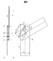
図3は、第1回動部12の概略構成を示す説明図である。第2回動部118、第3回動部122、第4回動部142は、第1回動部12と同様の構成であるため、これらの回動部の構成については説明を省略する。第1回動部12は、第1回動軸51と同心で連結された第1ローター61と、第1ローター61を回転させる第2ローター62と、第2ローター62を回転させる第3ローター63と、第3ローター63を回転させる圧電駆動装置64と有している。第1ローター61と第2ローター62と第3ローター63とは1組のギヤトレイン(被駆動部)として構成されている。圧電駆動装置64によって第3ローター63が回転すると、これに応じて第1ローター61が回転する。すると、第1ローター61の回転に応じて第1ローター61に連結された回動軸(第1回動軸51)が回転し、これに応じて第1連結部110がベース部材10に対して回動する。なお、ローターの数や各ローターのギア比は、駆動対象の軸の回転方向や要求されるトルク等に応じて任意に変更可能である。
B. Schematic configuration of rotating part:
FIG. 3 is an explanatory diagram showing a schematic configuration of the first rotating unit 12. Since the 2nd rotation part 118, the 3rd rotation part 122, and the 4th rotation part 142 are the structures similar to the 1st rotation part 12, description is abbreviate | omitted about the structure of these rotation parts. The first rotating unit 12 includes a first rotor 61 concentrically connected to the first rotating shaft 51, a second rotor 62 that rotates the first rotor 61, and a third rotor 63 that rotates the second rotor 62. And a piezoelectric drive device 64 that rotates the third rotor 63. The first rotor 61, the second rotor 62, and the third rotor 63 are configured as a set of gear trains (driven parts). When the third rotor 63 is rotated by the piezoelectric driving device 64, the first rotor 61 is rotated accordingly. Then, the rotation shaft (first rotation shaft 51) connected to the first rotor 61 rotates according to the rotation of the first rotor 61, and the first connection portion 110 moves relative to the base member 10 according to this. Rotate. The number of rotors and the gear ratio of each rotor can be arbitrarily changed according to the rotation direction of the shaft to be driven, the required torque, and the like.

圧電駆動装置64は、圧電体(圧電素子)651が設けられた振動板66を備えている。より具体的には、振動板66の表面と裏面とに、5つの圧電体651を含む振動体65がそれぞれ張り合わされることにより圧電駆動装置64が構成されている。   The piezoelectric drive device 64 includes a diaphragm 66 provided with a piezoelectric body (piezoelectric element) 651. More specifically, the piezoelectric driving device 64 is configured by attaching the vibrating bodies 65 including the five piezoelectric bodies 651 to the front surface and the back surface of the diaphragm 66.

振動体65を構成する5つの圧電体651は、それぞれ、圧電体と、圧電体を挟持する第1電極及び第2電極とを有している(図示省略)。なお、第1電極と第2電極のどちらか一方の電極は共通電極としてもよい。これらの圧電体651は、図2に示した制御部14に電気的に接続される。なお、振動体65に含まれる圧電体651は少なくとも1つあればよく、その数や配置は、これ以外の種々のものを採用可能である。また、振動体65は、振動板66の2つの面(表側の面及び裏側の面)のうちの一方の面だけに設けられていてもよい。   Each of the five piezoelectric bodies 651 constituting the vibrating body 65 includes a piezoelectric body and a first electrode and a second electrode that sandwich the piezoelectric body (not shown). Note that one of the first electrode and the second electrode may be a common electrode. These piezoelectric bodies 651 are electrically connected to the control unit 14 shown in FIG. Note that it is sufficient that at least one piezoelectric body 651 is included in the vibrating body 65, and various other types and arrangements can be employed. Further, the vibrating body 65 may be provided on only one of the two surfaces of the diaphragm 66 (the front surface and the back surface).

圧電駆動装置64(振動板66)の端部には、突起部67が設けられている。突起部67は、セラミックス(例えばAl)などの耐久性がある材料で形成されていることが好ましい。圧電駆動装置64の両側面には、圧電駆動装置64を支持するための複数の支持部68が、圧電駆動装置64の振動の節に対応する位置に設けられている。これらの支持部68は、振動板66と一体的に形成されている。なお、振動板66の同一の側面から突出している複数の支持部68同士は、連結板69を介して連結されていることが好ましい。 A protrusion 67 is provided at the end of the piezoelectric driving device 64 (the diaphragm 66). The protrusion 67 is preferably formed of a durable material such as ceramics (for example, Al 2 O 3 ). On both side surfaces of the piezoelectric driving device 64, a plurality of support portions 68 for supporting the piezoelectric driving device 64 are provided at positions corresponding to vibration nodes of the piezoelectric driving device 64. These support portions 68 are formed integrally with the diaphragm 66. In addition, it is preferable that the plurality of support portions 68 protruding from the same side surface of the diaphragm 66 are connected via a connecting plate 69.

図4は、圧電駆動装置64の動作原理について示す説明図である。圧電駆動装置64は、各圧電駆動装置64の圧電体651に一定周期で電圧を印加したときに、圧電駆動装置64の突起部67が伸縮又は楕円運動することによって動作する。すなわち、図4(a)に示すように、互いに対角線の位置にある2つの圧電体651a,651dを1組として、特定の周波数の電圧を印加すると、圧電駆動装置64は、屈曲して蛇行形状(S字形状)に変形し、突起部67の先端が特定の方向に往復運動するか、又は、楕円運動する。この結果、突起部67に接する第3ローター63(図3)が所定の方向に回転する。また、図4(b)に示すように、他の1組の圧電体651b,651cに特定の周波数の電圧を印加すると、第3ローター63は逆方向に回転する。なお、圧電駆動装置64や振動体65のこのような動作については、例えば、特開2004−320979号公報、又は、対応する米国特許第7224102号に記載されており、その開示内容は参照により組み込まれる。   FIG. 4 is an explanatory diagram showing the operation principle of the piezoelectric drive device 64. The piezoelectric driving device 64 operates when the protrusion 67 of the piezoelectric driving device 64 expands or contracts or elliptically moves when a voltage is applied to the piezoelectric body 651 of each piezoelectric driving device 64 at a constant period. That is, as shown in FIG. 4A, when a voltage of a specific frequency is applied to a pair of two piezoelectric bodies 651a and 651d that are diagonally located, the piezoelectric driving device 64 bends and meanders. The tip of the projection 67 reciprocates in a specific direction or elliptically moves. As a result, the third rotor 63 (FIG. 3) in contact with the protrusion 67 rotates in a predetermined direction. As shown in FIG. 4B, when a voltage having a specific frequency is applied to the other pair of piezoelectric bodies 651b and 651c, the third rotor 63 rotates in the reverse direction. Such operations of the piezoelectric driving device 64 and the vibrating body 65 are described in, for example, Japanese Patent Application Laid-Open No. 2004-320979 or the corresponding US Pat. No. 7,224,102, and the disclosure content thereof is incorporated by reference. It is.

C.関節機構の構造:
図5は、駆動装置1に備えられた関節機構90の構造を示す図である。図5には、第1部材20と第2部材30とが第3回動軸53によって接続されることにより構成された関節機構90の構造を示している。駆動装置1のベース部材10から第4連結部140(または固定部40)までには、各回動部を制御部14に電気的に接続するためのフラット型配線部材70が内部に挿通されている。そのため、関節機構90内にもフラット型配線部材70が配置されている。フラット型配線部材70とは、形状が平状で、曲げることが可能な配線部材である。本実施形態のフラット型配線部材70は、フレキシブル基板によって構成されている。フラット型配線部材70は、形状が全体として平状であれば、表面は平坦であっても凹凸状であってもよい。フラット型配線部材70としては、フレキシブル基板以外にも、例えば、被覆線を複数本並べて融着したフラットケーブルや、平板型の導体を複数本並べて被覆したリボン状のフレキシブルフラットケーブルなどを採用することができる。
C. Joint mechanism structure:
FIG. 5 is a diagram illustrating the structure of the joint mechanism 90 provided in the drive device 1. FIG. 5 shows a structure of the joint mechanism 90 configured by connecting the first member 20 and the second member 30 by the third rotating shaft 53. From the base member 10 of the drive device 1 to the fourth connecting portion 140 (or the fixing portion 40), a flat wiring member 70 for electrically connecting each rotating portion to the control portion 14 is inserted inside. . Therefore, the flat wiring member 70 is also arranged in the joint mechanism 90. The flat wiring member 70 is a wiring member that is flat and can be bent. The flat wiring member 70 of this embodiment is configured by a flexible substrate. As long as the shape of the flat wiring member 70 is flat as a whole, the surface may be flat or uneven. As the flat wiring member 70, in addition to the flexible substrate, for example, a flat cable in which a plurality of coated wires are arranged and fused, a ribbon-like flexible flat cable in which a plurality of flat conductors are arranged and covered, or the like is adopted. Can do.

図5(a)には、関節機構90の平面構造を模式的に示している。また、図5(b)には、関節機構90内に配置されているフラット型配線部材70の状態を示している。また、図5(c)には、図5(a)のX−X断面を模式的に示している。図5(c)では、第3回動軸53を回動させる第3回動部122の図示は省略している。   FIG. 5A schematically shows a planar structure of the joint mechanism 90. FIG. 5B shows a state of the flat wiring member 70 arranged in the joint mechanism 90. FIG. 5C schematically shows the XX cross section of FIG. In FIG. 5C, illustration of the third rotation unit 122 that rotates the third rotation shaft 53 is omitted.

図5(c)に示すように、第1部材20には、内部に第1空洞部21が設けられ、第2部材30には、内部に第2空洞部31が設けられている。フラット型配線部材70は、第1空洞部21および第2空洞部31を通り、第1部材20と第2部材30とに沿うように関節機構90内に設けられている。本実施形態では、フラット型配線部材70は、第3回動軸53上の上部の位置P1および下部の位置P2において、第1部材20および第2部材30に固定されている。なお、フラット型配線部材70は、第1部材20および第2部材30のいずれか一方に固定されていてもよい。   As shown in FIG. 5C, the first member 20 is provided with a first cavity portion 21 inside, and the second member 30 is provided with a second cavity portion 31 inside. The flat wiring member 70 is provided in the joint mechanism 90 along the first member 20 and the second member 30 through the first cavity portion 21 and the second cavity portion 31. In the present embodiment, the flat wiring member 70 is fixed to the first member 20 and the second member 30 at the upper position P1 and the lower position P2 on the third rotation shaft 53. The flat wiring member 70 may be fixed to one of the first member 20 and the second member 30.

フラット型配線部材70は、第3回動軸53付近において、第3回動軸53に平行な仮想線VLと3カ所で交わるように予め曲げられている。つまり、フラット型配線部材70は、関節機構90の第3回動軸53付近において、折り目がつかない程度に、Z折り状に予め曲げられている。このように、フラット型配線部材70が曲げられていれば、フラット型配線部材70を、その表面に垂直な軸(第3回動軸53)を中心として容易に曲げることができる。そのため、関節機構90を構成する第1部材20および第2部材30を、第3回動軸53周りにスムーズに回動させることができる。なお、図5には、第3回動軸53を有する関節機構90内にフラット型配線部材70が配置されている様子を示しているが、第3回動軸53と平行な軸である第2回動軸52を有する関節機構(第1副部材112と第2副部材114とによって構成される関節機構)についても、その内部には、フラット型配線部材70が、図5(c)に示すように予め曲げられて配置されている。   The flat type wiring member 70 is bent in advance in the vicinity of the third rotation shaft 53 so as to intersect with the virtual line VL parallel to the third rotation shaft 53 at three positions. That is, the flat-type wiring member 70 is bent in advance in a Z-fold shape in the vicinity of the third rotation shaft 53 of the joint mechanism 90 so as not to be folded. As described above, if the flat wiring member 70 is bent, the flat wiring member 70 can be easily bent around the axis (third rotation shaft 53) perpendicular to the surface thereof. Therefore, the first member 20 and the second member 30 constituting the joint mechanism 90 can be smoothly rotated around the third rotation shaft 53. FIG. 5 shows a state in which the flat wiring member 70 is arranged in the joint mechanism 90 having the third rotation shaft 53, but the first is a shaft parallel to the third rotation shaft 53. As for the joint mechanism (joint mechanism constituted by the first sub member 112 and the second sub member 114) having the two rotation shafts 52, a flat wiring member 70 is provided in the inside thereof as shown in FIG. As shown, it is pre-bent and arranged.

図6は、関節機構90の回転可能角度を説明するための図である。関節機構90の回動可能角度は、フラット型配線部材70の回動可能角度に応じて決まる。そのため、以下では、関節機構90の回動可能角度が、フラット型配線部材70の回動可能角度であるものとして説明する。図6(a)は、第1部材20と第2部材30とが回動していない場合のフラット型配線部材70の側面図を表し、図6(b)には、第1部材20と第2部材30とが回動している場合のフラット型配線部材70の平面図を表している。図6(a)には、フラット型配線部材70と仮想線VLとが交わる部分に黒丸を示している。フラット型配線部材70を第1部材20および第2部材30内に配置した場合、第2部材30が第1部材20に対して相対的に回動可能な角度は、以下のように規定することができる。   FIG. 6 is a view for explaining the rotatable angle of the joint mechanism 90. The pivotable angle of the joint mechanism 90 is determined according to the pivotable angle of the flat wiring member 70. Therefore, in the following description, it is assumed that the pivotable angle of the joint mechanism 90 is the pivotable angle of the flat wiring member 70. FIG. 6A shows a side view of the flat wiring member 70 when the first member 20 and the second member 30 are not rotated, and FIG. 6B shows the first member 20 and the second member 30. The top view of the flat type wiring member 70 in case the 2 member 30 is rotating is represented. In FIG. 6A, a black circle is shown at a portion where the flat wiring member 70 and the virtual line VL intersect. When the flat wiring member 70 is disposed in the first member 20 and the second member 30, the angle at which the second member 30 can be rotated relative to the first member 20 is defined as follows. Can do.

フラット型配線部材70が、第3回動軸53に平行な仮想線VLと3カ所(図6(a)参照)で交わる部分を有し、かつ、フラット型配線部材70が図5(c)に示したように第1部材20および第2部材30に固定された場合において、
図6(b)に示すように、フラット型配線部材70の幅をWとし、
図6(a)に示すように、第1部材20と第2部材30とが回動していない場合に、第1部材20および第2部材30が延びる方向Xにおいて、仮想線VLがフラット型配線部材70に2カ所で交わる位置の間の距離をLとしたときに、
以下の式(1)を満たすθの4倍の角度(4θ)まで、第2部材30は第1部材20に相対的に回動可能である。
The flat type wiring member 70 has portions intersecting with the virtual line VL parallel to the third rotation shaft 53 at three places (see FIG. 6A), and the flat type wiring member 70 is shown in FIG. When fixed to the first member 20 and the second member 30 as shown in FIG.
As shown in FIG. 6B, the width of the flat wiring member 70 is W,
As shown in FIG. 6A, when the first member 20 and the second member 30 are not rotating, the virtual line VL is a flat type in the direction X in which the first member 20 and the second member 30 extend. When the distance between positions intersecting the wiring member 70 at two locations is L,
The second member 30 is rotatable relative to the first member 20 up to an angle (4θ) that is four times θ that satisfies the following expression (1).

2Lcos2θ/(cos2θ+1)−Wtanθ>0 ・・・(1)   2L cos 2θ / (cos 2θ + 1) −W tan θ> 0 (1)

式(1)によって回動可能な角度が規定されるのは以下の理由による。まず、図6(b)に示されている長さAと長さBとは、第1部材20の回動角度にかかわらず、以下の式(2)の関係を常に満たす。長さAとは、フラット型配線部材70が曲げられている領域の、フラット型配線部材70の長さ方向に沿った中心線の長さである。長さBとは、その中心線の端から第3回動軸53までの距離Bである。
A+2B=2L ・・・(2)
次に、長さAは、図6(b)から以下の式(3)によって表すことができる。
A=2Bcos2θ ・・・(3)
この式(3)を式(2)に代入すると、
2Bcos2θ+2B=2L
となる。よって、式(2)の長さBは、以下のように表される。
B=L/(cos2θ+1)
この長さBを式(2)に代入すると、
A+2L/(cos2θ+1)=2L
となるため、
長さAは、以下の式(4)によって表すことが可能になる。
A=2Lcos2θ/(cos2θ+1) ・・・(4)
The reason why the pivotable angle is defined by the equation (1) is as follows. First, the length A and the length B shown in FIG. 6B always satisfy the relationship of the following formula (2) regardless of the rotation angle of the first member 20. The length A is the length of the center line along the length direction of the flat wiring member 70 in the region where the flat wiring member 70 is bent. The length B is a distance B from the end of the center line to the third rotation shaft 53.
A + 2B = 2L (2)
Next, the length A can be expressed by the following equation (3) from FIG.
A = 2B cos 2θ (3)
Substituting this equation (3) into equation (2),
2B cos 2θ + 2B = 2L
It becomes. Therefore, the length B of Expression (2) is expressed as follows.
B = L / (cos 2θ + 1)
Substituting this length B into equation (2),
A + 2L / (cos2θ + 1) = 2L
So that
The length A can be expressed by the following equation (4).
A = 2L cos 2θ / (cos 2θ + 1) (4)

次に、フラット型配線部材70が折り曲げられている領域の、フラット型配線部材70の最も短い長さCは、図6(b)に示す角度θを用いると、次の式(5)のように表すことができる。
C=A−Wtanθ ・・・(5)
第1部材20が回動する際には、Cは0よりも大きい必要があるから、式(5)は、以下の式(6)のように表される。
A−Wtanθ>0 ・・・(6)
この式(6)に、上記式(4)によって表される長さAを代入すれば、以下のようになり、上記式(1)が導き出される。
2Lcos2θ/(cos2θ+1)−Wtanθ>0
Next, the shortest length C of the flat wiring member 70 in the region where the flat wiring member 70 is bent is expressed by the following equation (5) using the angle θ shown in FIG. Can be expressed as
C = A−Wtanθ (5)
When the first member 20 rotates, C needs to be larger than 0, and therefore the equation (5) is expressed as the following equation (6).
A-Wtanθ> 0 (6)
Substituting the length A represented by the above equation (4) into this equation (6) yields the following equation (1).
2L cos 2θ / (cos 2θ + 1) −W tan θ> 0

以上より、フラット型配線部材70の幅Wと、仮想線VLがフラット型配線部材70に2カ所で交わる2つの位置の間の距離Lとが定まれば、上記式(1)により、関節機構90の回動可能角度が定まる。   From the above, if the width W of the flat wiring member 70 and the distance L between the two positions where the virtual line VL intersects the flat wiring member 70 at two locations are determined, the joint mechanism is obtained by the above equation (1). 90 pivotable angles are determined.

なお、本実施形態では、フラット型配線部材70を、第1部材20および第2部材30に固定しているが、フラット型配線部材70は、第1部材20および第2部材30内に固定させないことも可能である。また、本実施形態では、関節機構90の内部にフラット型配線部材70が設けられているが、フラット型配線部材70は、関節機構90の外部に設けられていてもよい。また、図5では、フラット型配線部材70が、第3回動軸53に平行な仮想線VLと3カ所で交わるように曲げられている例を示しているが、フラット型配線部材70は、仮想線VLと4カ所以上(好ましくは、4カ所以上、かつ、奇数箇所)で交わるように曲げられていてもよい。   In the present embodiment, the flat wiring member 70 is fixed to the first member 20 and the second member 30, but the flat wiring member 70 is not fixed inside the first member 20 and the second member 30. It is also possible. In the present embodiment, the flat wiring member 70 is provided inside the joint mechanism 90, but the flat wiring member 70 may be provided outside the joint mechanism 90. FIG. 5 shows an example in which the flat wiring member 70 is bent so as to intersect with the virtual line VL parallel to the third rotation shaft 53 at three locations. The imaginary line VL may be bent so as to intersect at four or more places (preferably, four or more places and odd places).

D.駆動装置の作用・効果:
図7は、図2におけるA矢視図である。図8は、図7におけるB矢視図である。図9は、図8におけるC矢視図である。図7に示されているように、駆動装置1を手に装着すると、ベース部材10が手の甲に配置され、第1回動軸51が人差し指中手骨80に沿って配置される。そのため、第1回動軸51に接続された第1副部材112は、親指の付け根の背側と平行を保つ。しかし、第1回動軸51が人差し指中手骨80に沿って配置されたとしても、これらの軸は同一の位置にはないため、第1回動軸51を中心に第1副部材112が回動すると、親指の第3関節83から第1副部材112までの高さγ(図7,9参照)と、親指の第2関節84と第3関節83とを結ぶ親指中手骨82から第2回動軸52までの距離α(図7,8参照)と、が親指の動きによって変化する。
D. Action and effect of drive unit:
FIG. 7 is a view taken in the direction of arrow A in FIG. FIG. 8 is a view taken in the direction of arrow B in FIG. FIG. 9 is a view taken in the direction of arrow C in FIG. As shown in FIG. 7, when the driving device 1 is attached to the hand, the base member 10 is disposed on the back of the hand, and the first rotation shaft 51 is disposed along the index finger metacarpal bone 80. Therefore, the first sub member 112 connected to the first rotation shaft 51 is kept parallel to the back side of the base of the thumb. However, even if the first rotation shaft 51 is disposed along the index finger metacarpal bone 80, these shafts are not in the same position, so the first sub member 112 is centered on the first rotation shaft 51. When rotating, the height γ from the third joint 83 of the thumb to the first sub-member 112 (see FIGS. 7 and 9) and the thumb metacarpal 82 connecting the second joint 84 and the third joint 83 of the thumb. The distance α (see FIGS. 7 and 8) to the second rotation shaft 52 and the movement of the thumb change.

これに対して、本実施形態の駆動装置1は、親指の動きに応じて距離αが変動した場合であっても、図8に示すように、第2副部材114が第2回動軸52周りに回動し、第3連結部130が第3回動軸53周りに回動し、第2連結部120が第1スライド機構117によって摺動することによって、その動きに適切に追従することができる。また、本実施形態の駆動装置1は、親指の動きに応じて高さγが変動した場合であっても、図9に示すように、第4回動軸54周りに第4連結部140が回動し、第5回動軸55周りに固定部40が回動し、更に、固定部40と第5連結部150とが第2スライド機構44によって摺動することによって、その動きに適切に追従することができる。   In contrast, in the driving device 1 of the present embodiment, even when the distance α varies according to the movement of the thumb, as shown in FIG. The third connecting part 130 rotates around the third rotating shaft 53 and the second connecting part 120 slides by the first slide mechanism 117 so as to appropriately follow the movement. Can do. Further, in the driving device 1 of the present embodiment, even when the height γ varies according to the movement of the thumb, as shown in FIG. 9, the fourth connecting portion 140 is provided around the fourth rotation shaft 54. The fixed portion 40 is rotated around the fifth rotation shaft 55, and the fixed portion 40 and the fifth connecting portion 150 are slid by the second slide mechanism 44. Can follow.

更に、本実施形態では、各可動部材が、上記のように動作する際に、第1回動部12が第1回動軸51を駆動し、第4回動部142が第4回動軸54を駆動することによって、親指の屈曲動作を補助することができる。また、第2回動部118が第2回動軸52を駆動し、第3回動部122が第3回動軸53を駆動することによって、親指の開閉動作を補助することができる。つまり、本実施形態の駆動装置1は、親指の動きに応じて高さγと距離αとが変動したとしても、その動きに各可動部材を追従させつつ、各回動部によって親指の動きを適切に補助することができる。そのため、親指の関節に負担をかけることなく、自由度の高い親指の動きを補助することができる。
そのほか、本実施形態によれば、以下のような効果を奏することができる。
Further, in the present embodiment, when each movable member operates as described above, the first rotating portion 12 drives the first rotating shaft 51 and the fourth rotating portion 142 is the fourth rotating shaft. By driving 54, the bending motion of the thumb can be assisted. In addition, the second turning unit 118 drives the second turning shaft 52 and the third turning unit 122 drives the third turning shaft 53, so that the opening / closing operation of the thumb can be assisted. That is, even if the height γ and the distance α fluctuate according to the movement of the thumb, the driving device 1 according to the present embodiment appropriately moves the thumb by each rotating unit while causing each movable member to follow the movement. Can assist. Therefore, it is possible to assist the thumb movement with a high degree of freedom without imposing a burden on the joint of the thumb.
In addition, according to the present embodiment, the following effects can be obtained.

本実施形態では、手の甲に配置されるベース部材10に対して、手の人差し指中手骨80に沿った第1回動軸51周りに回動可能に第1部材20が設けられている。そのため、親指の腹側が、手の平側に向く動きを第1部材20によって良好に補助することができる。   In the present embodiment, the first member 20 is provided to be rotatable around the first rotation shaft 51 along the index finger metacarpal 80 of the hand with respect to the base member 10 disposed on the back of the hand. Therefore, the movement of the thumb belly side toward the palm side can be favorably assisted by the first member 20.

また、本実施形態の駆動装置1は、第1部材20を第1回動軸51周りに回動させる第1回動部12を備えている。そのため、第1部材20を積極的に回動させることができ、その結果、親指の腹が手の平側に向く動きをより良好に補助することができる。   In addition, the driving device 1 according to the present embodiment includes the first rotation unit 12 that rotates the first member 20 around the first rotation shaft 51. Therefore, the first member 20 can be positively rotated, and as a result, the movement of the thumb belly toward the palm side can be better assisted.

また、本実施形態では、各回動部が、圧電体651や振動板66によって構成されているため、回動部を小さく構成することができる。そのため、駆動装置1を小型化することができる。また、本実施形態では、振動板が被駆動部(ギヤトレイン)に直接的に当たるのではなく、振動板66に設けられた突起部67が被駆動部に当たるため、回動部の耐久性を高めることができる。   Moreover, in this embodiment, since each rotation part is comprised by the piezoelectric material 651 and the diaphragm 66, a rotation part can be comprised small. Therefore, the drive device 1 can be reduced in size. In the present embodiment, the diaphragm does not directly contact the driven part (gear train), but the protrusion 67 provided on the diaphragm 66 contacts the driven part, so that the durability of the rotating part is improved. be able to.

また、本実施形態では、第1部材20と手との間に弾性部材116が備えられているので、第1部材20と手とが擦れることを抑制することができる。そのため、第1部材20を、第1回動軸51周りにスムーズに回動させることができる。   Moreover, in this embodiment, since the elastic member 116 is provided between the 1st member 20 and a hand, it can suppress that the 1st member 20 and a hand rub. Therefore, the first member 20 can be smoothly rotated around the first rotation shaft 51.

また、本実施形態の駆動装置1は、第1部材20と第2部材30とが第3回動部122によって第1回動方向に回動され、しかも、ベース部材10と第2部材30との距離が可変される。そのため、第2部材30によって親指の動きを良好に補助することができる。また、本実施形態において、第1回動方向とは、手の親指が人差し指に対して開閉する方向であるため、親指の動きをより良好に補助することができる。   Further, in the driving device 1 of the present embodiment, the first member 20 and the second member 30 are rotated in the first rotation direction by the third rotation unit 122, and the base member 10 and the second member 30 are The distance of is variable. Therefore, the movement of the thumb can be favorably supported by the second member 30. Further, in the present embodiment, the first rotation direction is a direction in which the thumb of the hand opens and closes with respect to the index finger, so that the movement of the thumb can be better supported.

また、本実施形態では、第1部材20に備えられた第1連結部110と第2連結部120とが、接近および離間することにより、ベース部材10と第2部材30との距離が可変する。そのため、簡易な構成でベース部材10と第2部材30との距離を可変させることができる。また、このような構成であれば、第1部材20を小型化することができる。   In the present embodiment, the distance between the base member 10 and the second member 30 varies as the first connecting portion 110 and the second connecting portion 120 provided in the first member 20 approach and separate from each other. . Therefore, the distance between the base member 10 and the second member 30 can be varied with a simple configuration. Moreover, if it is such a structure, the 1st member 20 can be reduced in size.

また、本実施形態では、第1部材20を構成する第1連結部110が、相対的に回動可能な第1副部材112と第2副部材114とによって構成されている。そのため、第1連結部110の動きの自由度が高まり、親指の動きをより良好に補助することができる。   Moreover, in this embodiment, the 1st connection part 110 which comprises the 1st member 20 is comprised by the 1st submember 112 and the 2nd submember 114 which can rotate relatively. Therefore, the freedom degree of movement of the 1st connection part 110 increases, and it can assist thumb movement more favorably.

また、本実施形態の駆動装置1は、第2副部材114を第1副部材112に対して相対的に回動させる第2回動部118を備えている。そのため、第2副部材114を第1副部材112に対して積極的に回動させることができ、その結果、親指の動きをより良好に補助することができる。   In addition, the driving device 1 of the present embodiment includes a second rotating unit 118 that rotates the second sub member 114 relative to the first sub member 112. Therefore, the second sub member 114 can be positively rotated with respect to the first sub member 112, and as a result, the movement of the thumb can be assisted better.

また、本実施形態では、第2部材30が、第3連結部130と第4連結部140と第5連結部150と、を備えており、第4連結部140および第5連結部150が、第3連結部130に対して、第1回動方向とは異なる第2回動方向に回動可能である。そのため、駆動装置1の動きの自由度が高まり、親指の動きをより良好に補助することができる。   Moreover, in this embodiment, the 2nd member 30 is provided with the 3rd connection part 130, the 4th connection part 140, and the 5th connection part 150, and the 4th connection part 140 and the 5th connection part 150 are the following. The third connecting part 130 can be rotated in a second rotation direction different from the first rotation direction. Therefore, the degree of freedom of movement of the driving device 1 is increased, and the thumb movement can be assisted better.

また、本実施形態の駆動装置1は、第4連結部140を、第3連結部130に対して相対的に第2回動方向に回動させる第4回動部142を備えている。そのため、第4連結部140を第3連結部130に対して積極的に回動させることができ、その結果、親指の動きをより良好に補助することができる。また、本実施形態では、第2回動方向とは、親指が屈曲する方向であるため、親指の動きを、より良好に補助することができる。   In addition, the drive device 1 according to the present embodiment includes a fourth rotating unit 142 that rotates the fourth connecting unit 140 in the second rotating direction relative to the third connecting unit 130. Therefore, the 4th connection part 140 can be actively rotated with respect to the 3rd connection part 130, As a result, a motion of a thumb can be assisted more favorably. In the present embodiment, the second rotation direction is a direction in which the thumb bends, so that the movement of the thumb can be assisted better.

また、本実施形態では、親指に装着される固定部40が第2部材30に設けられており、この固定部40は、親指の基節骨81に沿って相対的に摺動可能である。よって、親指の動きをより良好に補助することができる。   Further, in the present embodiment, the fixing part 40 to be attached to the thumb is provided on the second member 30, and the fixing part 40 can be relatively slid along the proximal phalange 81 of the thumb. Therefore, the movement of the thumb can be assisted better.

また、本実施形態の関節機構90には、第1部材20と第2部材30とに沿ってフラット型配線部材70が設けられており、フラット型配線部材70は、第3回動軸53に平行な仮想線VLと3カ所以上交わる部分を有するように曲げられている。そのため、第1部材20と第2部材30とが第3回動軸53周りに回動された場合であっても、フラット型配線部材70をその動きに追従させることができるので、フラット型配線部材70の存在によって、関節機構90の動きが制限されてしまうことを抑制することができる。   Further, the joint mechanism 90 of the present embodiment is provided with a flat wiring member 70 along the first member 20 and the second member 30, and the flat wiring member 70 is attached to the third rotation shaft 53. It is bent so as to have three or more intersecting portions with the parallel virtual line VL. Therefore, even when the first member 20 and the second member 30 are rotated around the third rotation shaft 53, the flat wiring member 70 can follow the movement, so that the flat wiring The presence of the member 70 can suppress the movement of the joint mechanism 90 from being restricted.

また、本実施形態では、フラット型配線部材70は、第1部材20および第2部材30の少なくとも一方に固定されているため、関節機構90に対してぐらつくことを抑制することができる。   In the present embodiment, the flat wiring member 70 is fixed to at least one of the first member 20 and the second member 30, and therefore can be prevented from wobbling with respect to the joint mechanism 90.

また、本実施形態では、第1部材20は、第1空洞部21を有しており、第2部材30は、第2空洞部31を有している。そして、フラット型配線部材70は、これら第1空洞部21および第2空洞部31を通る。そのため、関節機構90を小型化することができる。   In the present embodiment, the first member 20 has a first cavity portion 21, and the second member 30 has a second cavity portion 31. The flat wiring member 70 passes through the first cavity portion 21 and the second cavity portion 31. Therefore, the joint mechanism 90 can be reduced in size.

また、本実施形態では、フラット型配線部材70は、フレキシブル基板によって構成されている。そのため、特別な材料によってフラット型配線部材を構成しなくてもよい。よって、関節機構90の製造コストを削減することができる。   Moreover, in this embodiment, the flat type wiring member 70 is comprised with the flexible substrate. Therefore, the flat wiring member does not need to be configured with a special material. Therefore, the manufacturing cost of the joint mechanism 90 can be reduced.

また、本実施形態では、上記式(1)によって、関節機構90の回動可能角度が規定される。そのため、関節機構90の設計を容易に行うことができる。   In the present embodiment, the pivotable angle of the joint mechanism 90 is defined by the above equation (1). Therefore, the joint mechanism 90 can be easily designed.

また、本実施形態では、フラット型配線部材70が設けられた第1部材20と第2部材30とが第3回動部122によって回動されるが、本実施形態では、フラット型配線部材70は上記のように予め曲げられているため、第3回動部122に負担がかかることを抑制することができる。   In the present embodiment, the first member 20 and the second member 30 provided with the flat wiring member 70 are rotated by the third rotating portion 122. In the present embodiment, the flat wiring member 70 is provided. Since it is bent in advance as described above, it is possible to prevent the third rotating part 122 from being burdened.

E.変形例:
<第1,2変形例>
図10は、駆動装置の第1の変形例を示す図である。図11は、駆動装置の第2の変形例を示す図である。上記実施形態の駆動装置1では、第1部材20に備えられた第1スライド機構117によって第2連結部120と第1連結部110とを伸縮させることにより、ベース部材10と第2部材30との間の距離を調整している。これに対して、第1部材20は、ベース部材10と第2部材30との間の距離を調整可能であれば、どのような構造であってもよい。例えば、図10に示した駆動装置1aは、第1部材20aの一部が、蛇腹状の部材によって伸縮可能に構成されている。このような構成によっても、上記実施形態と同様に、ベース部材10と第2部材30との間の距離を調整することができる。また、図11に示した駆動装置1bは、第1部材20bの一部が屈曲可能に構成されている。このような構成であっても、上記実施形態と同様に、ベース部材10と第2部材30との間の距離を調整可能である。
E. Variation:
<First and second modifications>
FIG. 10 is a diagram illustrating a first modification of the driving device. FIG. 11 is a diagram illustrating a second modification of the driving device. In the driving device 1 of the above embodiment, the
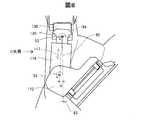
 base member 10 and the second member 30 are expanded and contracted by the first connecting mechanism 110 and the second connecting portion 120 and the first connecting portion 110 being extended and contracted by the first slide mechanism 117. The distance between is adjusted. On the other hand, the first member 20 may have any structure as long as the distance between the base member 10 and the second member 30 can be adjusted. For example, the drive device 1a shown in FIG. 10 is configured such that a part of the first member 20a can be expanded and contracted by a bellows-like member. Also with such a configuration, the distance between the base member 10 and the second member 30 can be adjusted as in the above embodiment. Further, the drive device 1b shown in FIG. 11 is configured such that a part of the first member 20b can be bent. Even with such a configuration, the distance between the base member 10 and the second member 30 can be adjusted, as in the above embodiment.

<第3,4変形例>
図12は、駆動装置の第3の変形例を示す図である。図13は、駆動装置の第4の変形例を示す図である。上記実施形態の駆動装置1は、第2回動軸52と第3回動軸53とを備えている。しかし、これらの軸は、いずれか一方(好ましくは、第2回動軸52の方)を省略してもよい。例えば、図12に示した駆動装置1cは、第2回動軸52が省略されている。そのため、第2回動部118も省略されており、更に、第1副部材112と第2副部材114とが一体化され、1つの第1連結部110cが構成されている。また、図13に示した駆動装置1dは、第3回動軸53が省略されている。そのため、第3回動部122も省略されており、更に、第2連結部と第3連結部とが一体化された連結部125として構成されている。これらの図に示したように、第2回動軸52と第3回動軸53とのどちらか一方が省略された場合であっても、各可動部材の遊びによって、省略された軸の可動範囲を吸収することができる。また、図12や図13に示したように、回動軸の数を削減すれば、それだけ、回動部の数を削減することができるため、駆動装置1の小型化や軽量化、省電力化を図ることができる。
<Third and fourth modifications>
FIG. 12 is a diagram illustrating a third modification of the driving device. FIG. 13 is a diagram illustrating a fourth modification of the driving device. The drive device 1 according to the embodiment includes a
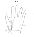
 second rotation shaft 52 and a third rotation shaft 53. However, either one of these axes (preferably, the second rotating shaft 52) may be omitted. For example, in the driving device 1c shown in FIG. 12, the second rotating shaft 52 is omitted. Therefore, the second rotating portion 118 is also omitted, and the first sub member 112 and the second sub member 114 are integrated to form one first connecting portion 110c. Further, in the driving device 1d shown in FIG. 13, the third rotation shaft 53 is omitted. Therefore, the 3rd rotation part 122 is also abbreviate | omitted, Furthermore, it comprises as the connection part 125 with which the 2nd connection part and the 3rd connection part were integrated. As shown in these drawings, even if one of the second rotation shaft 52 and the third rotation shaft 53 is omitted, the movement of the omitted shaft is caused by the play of each movable member. The range can be absorbed. Further, as shown in FIGS. 12 and 13, if the number of rotating shafts is reduced, the number of rotating parts can be reduced accordingly, so that the drive device 1 can be reduced in size, weight, and power saving. Can be achieved.

<第5変形例>
図14は、駆動装置の第5の変形例を示す図である。上記実施形態の駆動装置1は、第1部材20と第2部材30とを備えているが、図14に示すように、第2部材30は省略してもよい。この場合、第1部材20eは、第2副部材114を備えていなくてもよい。このような構成によれば、親指が人差し指中手骨80に沿った軸周りに回動することを補助する単機能な駆動装置1eを提供することができる。
<Fifth Modification>
FIG. 14 is a diagram illustrating a fifth modification of the drive device. The drive device 1 of the above embodiment includes the first member 20 and the second member 30, but the second member 30 may be omitted as shown in FIG. In this case, the first member 20e may not include the second sub member 114. According to such a configuration, it is possible to provide a single-function drive device 1e that assists in turning the thumb around an axis along the index finger metacarpal bone 80.

<第6変形例>
上記実施形態では、第1回動軸51を駆動する第1回動部12が、ベース部材10に備えられているが、第1回動部12は、第1部材20に備えられていてもよい。また、上記実施形態では、第2回動軸52を駆動する第2回動部118が、第1副部材112に備えられているが、第2回動部118は第2副部材114に備えられていてもよい。また、上記実施形態では、第3回動軸53を駆動する第3回動部122が、第2連結部120に備えられているが、第3回動部122は、第3連結部130に備えられていてもよい。また、上記実施形態では、第4回動軸54を駆動する第4回動部142が、第4連結部140に備えられているが、第4回動部142は、第3連結部130に備えられていてもよい。
<Sixth Modification>
In the above-described embodiment, the base member 10 includes the first rotating unit 12 that drives the first rotating shaft 51, but the first rotating unit 12 may be included in the first member 20. Good. In the above-described embodiment, the second rotating portion 118 that drives the second rotating shaft 52 is provided in the first sub member 112, but the second rotating portion 118 is provided in the second sub member 114. It may be done. In the above embodiment, the third rotating part 122 that drives the third rotating shaft 53 is provided in the second connecting part 120, but the third rotating part 122 is connected to the third connecting part 130. It may be provided. Moreover, in the said embodiment, although the 4th rotation part 142 which drives the 4th rotation axis | shaft 54 is provided in the 4th connection part 140, the 4th rotation part 142 is provided in the 3rd connection part 130. FIG. It may be provided.

<第7変形例>
上記実施形態では、図2および図3に示したように、圧電体651を用いた回動部によって各回動軸を駆動しているが、各回動軸は、各種アクチュエーターによって駆動してもよい。例えば、各回動軸を駆動するアクチュエーターとして、一般的な小型モーターや電磁アクチュエーター等を利用することが可能である。また、ワイヤーとワイヤーの張力を変化させるテンショナーとから構成されるアクチュエーターや、ホースとホース内の油圧や空気圧を変化させるポンプとから構成されるアクチュエーター等を利用することも可能である。
<Seventh Modification>
In the above embodiment, as shown in FIGS. 2 and 3, each rotation axis is driven by a rotation unit using the piezoelectric body 651. However, each rotation axis may be driven by various actuators. For example, a general small motor, an electromagnetic actuator, or the like can be used as an actuator for driving each rotation shaft. It is also possible to use an actuator composed of a wire and a tensioner that changes the tension of the wire, an actuator composed of a hose and a pump that changes the hydraulic pressure and air pressure in the hose, and the like.

<第8変形例>
上記実施形態におけるフラット型配線部材70は、駆動装置1に備えられた関節機構90に限らず、他の任意の関節機構に備えられてもよい。また、フラット型配線部材70が挿通された関節機構は、回動部等のアクチュエーターを備えていてもよいし、備えていなくてもよい。また、駆動装置1は、フラット型配線部材70に限らず、他の形態の配線部材によって配線が行われていてもよい。例えば、一般的な被覆線や、複数の被覆線をシースによってまとめたケーブルなどによって配線が行われていてもよい。
<Eighth Modification>
The flat wiring member 70 in the above embodiment is not limited to the joint mechanism 90 provided in the drive device 1 and may be provided in any other joint mechanism. Further, the joint mechanism through which the flat wiring member 70 is inserted may or may not include an actuator such as a rotating part. In addition, the driving device 1 is not limited to the flat wiring member 70, and wiring may be performed by another form of wiring member. For example, wiring may be performed by a general covered wire or a cable in which a plurality of covered wires are collected by a sheath.

<第9変形例>
上記実施形態では、駆動装置1は、回動部として、第1回動部12と、第2回動部118と、第3回動部122と、第4回動部142とを備えているが、これらすべての回動部を備えていなくてもよい。例えば、動きを補助する必要のない関節を駆動するための回動部は省略することが可能である。
<Ninth Modification>
In the above-described embodiment, the drive device 1 includes the first rotation unit 12, the second rotation unit 118, the third rotation unit 122, and the fourth rotation unit 142 as the rotation unit. However, it is not necessary to provide all these rotating parts. For example, a rotation unit for driving a joint that does not need to assist movement can be omitted.

<第10変形例>
上記実施形態では、駆動装置1は、人の手の親指に装着されることが想定されているが、駆動装置1は、人に限らず、動物などの生体の関節や、ロボットなど生体以外の関節の動きを補助する用途に用いてもよい。
<10th modification>
In the above embodiment, it is assumed that the driving device 1 is mounted on the thumb of a human hand. However, the driving device 1 is not limited to a human being, but a living body joint such as an animal or a robot other than a living body such as a robot. You may use for the use which assists the motion of a joint.

本発明は、上述の実施形態や変形例に限られるものではなく、その趣旨を逸脱しない範囲において種々の構成で実現することができる。例えば、発明の概要の欄に記載した各形態中の技術的特徴に対応する実施形態や変形例中の技術的特徴は、上述の課題の一部又は全部を解決するために、あるいは、上述の効果の一部又は全部を達成するために、適宜、差し替えや、組み合わせを行うことが可能である。また、その技術的特徴が本明細書中に必須なものとして説明されていなければ、適宜、削除することが可能である。   The present invention is not limited to the above-described embodiments and modifications, and can be realized with various configurations without departing from the spirit thereof. For example, the technical features in the embodiments and modifications corresponding to the technical features in each embodiment described in the summary section of the invention are intended to solve part or all of the above-described problems, or In order to achieve part or all of the effects, replacement or combination can be performed as appropriate. Further, if the technical feature is not described as essential in the present specification, it can be deleted as appropriate.

1,1a,1b,1c,1d,1e…駆動装置
10…ベース部材
12…第1回動部
14…制御部
20,20a,20b,20e…第1部材
21…第1空洞部
30…第2部材
31…第2空洞部
40…固定部
42…装着バンド
44…第2スライド機構
51…第1回動軸
52…第2回動軸
53…第3回動軸
54…第4回動軸
55…第5回動軸
61…第1ローター
62…第2ローター
63…第3ローター
64…圧電駆動装置
65…振動体
66…振動板
67…突起部
68…支持部
69…連結板
70…フラット型配線部材
80…人差し指中手骨
81…親指の基節骨
82…親指中手骨
83…親指の第3関節
84…親指の第2関節
90…関節機構
110,110c…第1連結部
112…第1副部材
114…第2副部材
115…開口部
116…弾性部材
117…第1スライド機構
118…第2回動部
120…第2連結部
122…第3回動部
125…連結部
130…第3連結部
140…第4連結部
142…第4回動部
150…第5連結部
651,651a,651b,651c,651d…圧電体
VL…仮想線
DESCRIPTION OF SYMBOLS 1, 1a, 1b, 1c, 1d, 1e ... Drive device 10 ... Base member 12 ... 1st rotation part 14 ... Control part 20, 20a, 20b, 20e ... 1st member 21 ... 1st cavity part 30 ... 2nd Member 31 ... 2nd cavity 40 ... Fixing part 42 ... Mounting band 44 ... 2nd slide mechanism 51 ... 1st rotating shaft 52 ... 2nd rotating shaft 53 ... 3rd rotating shaft 54 ... 4th rotating shaft 55 ... 5th rotation axis 61 ... 1st rotor 62 ... 2nd rotor 63 ... 3rd rotor 64 ... Piezoelectric drive device 65 ... Vibrating body 66 ... Diaphragm 67 ... Projection part 68 ... Supporting part 69 ... Connecting plate 70 ... Flat type Wiring member 80 ... metacarpal bone of index finger 81 ... proximal phalanx of thumb 82 ... metacarpal bone of thumb 83 ... third joint of thumb 84 ... second joint of thumb 90 ... joint mechanism 110, 110c ... first connecting portion 112 ... first 1 sub member 114 ... 2nd sub member 115 ... opening DESCRIPTION OF SYMBOLS 16 ... Elastic member 117 ... 1st slide mechanism 118 ... 2nd rotation part 120 ... 2nd connection part 122 ... 3rd rotation part 125 ... connection part 130 ... 3rd connection part 140 ... 4th connection part 142 ... 4th Rotating part 150 ... Fifth connecting part 651, 651a, 651b, 651c, 651d ... Piezoelectric body VL ... Virtual line

Claims (4)

手の甲に配置されるベース部材と、
前記手の親指の背側に配置され、前記ベース部材に回動可能に設けられた第1部材と、
を備え、
前記第1部材は、前記手の人差し指中手骨の長手方向に沿った回動軸周りに回動可能であり、
前記第1部材を、前記回動軸周りに回動させる回動部、を備え、
前記回動部は、
圧電体を含む振動板と、
前記振動板が接触して駆動される被駆動部と、を備える
駆動装置。
A base member arranged on the back of the hand ;
A first member disposed on the back side of the thumb of the hand and rotatably provided on the base member;
With
Said first member, Ri rotatable der around a rotary shaft along the longitudinal direction of the front Kite index finger metacarpal,
A rotation unit that rotates the first member around the rotation axis;
The rotating part is
A diaphragm including a piezoelectric body;
A driven portion that is driven by contact with the diaphragm.
Drive device.
請求項に記載の駆動装置であって、
前記振動板には突起部が設けられており、
前記突起部が前記被駆動部に接触する、駆動装置。
The drive device according to claim 1 ,
The diaphragm is provided with a protrusion,
The drive device in which the protrusion comes into contact with the driven part.
請求項1または請求項に記載の駆動装置であって、
前記第1部材と前記手との間に設けられる弾性部材、を備える駆動装置。
The drive device according to claim 1 or 2 , wherein
A drive device comprising: an elastic member provided between the first member and the hand.
手の甲に配置されるベース部材と、
前記手の親指の背側に配置され、前記ベース部材に回動可能に設けられた第1部材と、
を備える駆動装置の駆動方法であって、
圧電体を含む振動板と前記振動板が接触して駆動される被駆動部とを備える回動部が、前記第1部材を、前記手の人差し指中手骨の長手方向に沿った回動軸周りに回動させる
駆動方法。
A base member arranged on the back of the hand ;
A first member disposed on the back side of the thumb of the hand and rotatably provided on the base member;
A drive method for a drive device comprising:
Rotating portion and a driven portion to which the diaphragm and the diaphragm including the piezoelectric element is driven in contact with the pre-Symbol first member, along the longitudinal direction of the index finger metacarpals of the hand rotation Drive method to rotate around the axis.
JP2014185853A 2014-09-12 2014-09-12 Driving device and driving method thereof Active JP6435729B2 (en)

Priority Applications (3)

Application Number Priority Date Filing Date Title
JP2014185853A JP6435729B2 (en) 2014-09-12 2014-09-12 Driving device and driving method thereof
CN201510543154.XA CN105411810A (en) 2014-09-12 2015-08-28 Driving apparatus and driving method therefor
US14/851,440 US10271967B2 (en) 2014-09-12 2015-09-11 Driving apparatus and driving method therefor

Applications Claiming Priority (1)

Application Number Priority Date Filing Date Title
JP2014185853A JP6435729B2 (en) 2014-09-12 2014-09-12 Driving device and driving method thereof

Publications (3)

Publication Number Publication Date
JP2016055078A JP2016055078A (en) 2016-04-21
JP2016055078A5 JP2016055078A5 (en) 2017-07-20
JP6435729B2 true JP6435729B2 (en) 2018-12-12

Family

ID=55756747

Family Applications (1)

Application Number Title Priority Date Filing Date
JP2014185853A Active JP6435729B2 (en) 2014-09-12 2014-09-12 Driving device and driving method thereof

Country Status (1)

Country Link
JP (1) JP6435729B2 (en)

Families Citing this family (1)

* Cited by examiner, † Cited by third party
Publication number Priority date Publication date Assignee Title
CN109893402B (en) * 2019-04-17 2023-11-28 北京因时机器人科技有限公司 Exoskeleton hand rehabilitation robot

Family Cites Families (3)

* Cited by examiner, † Cited by third party
Publication number Priority date Publication date Assignee Title
JP2002345861A (en) * 2001-05-29 2002-12-03 Harada Denshi Kogyo Kk Finger motion auxiliary device
US8574178B2 (en) * 2009-05-26 2013-11-05 The Hong Kong Polytechnic University Wearable power assistive device for helping a user to move their hand
JP2012253990A (en) * 2011-06-07 2012-12-20 Seiko Epson Corp Piezoelectric actuator, robot hand, and robot

Also Published As

Publication number Publication date
JP2016055078A (en) 2016-04-21

Similar Documents

Publication Publication Date Title
US10271967B2 (en) Driving apparatus and driving method therefor
CN104887364B (en) Articulations digitorum manus driving device
JP6693190B2 (en) Hand mechanism
US9248575B2 (en) Robot hand and robot
KR101515951B1 (en) Apparatus for exercising of finger
US9505134B2 (en) Lower robotic arm assembly having a plurality of tendon driven digits
US20080023974A1 (en) Joint apparatus and hand apparatus for robot using the same
JP7009072B2 (en) Finger mechanism and humanoid hand incorporating this finger mechanism
KR102009311B1 (en) Hand of robot
CN108673539B (en) Mechanical thumb and mechanical arm
WO2005095066A1 (en) Robot hand
JP6016453B2 (en) Hand Exo Skeleton Device with Three-layer Linked Spring Slide Mechanism
JP4512194B2 (en) Robot arm
KR102184066B1 (en) Hand mechanism
JP2013169633A (en) Finger mechanism for robot hand and robot hand provided with the same
JP2016150429A (en) Joint mechanism
JP6435729B2 (en) Driving device and driving method thereof
KR101258738B1 (en) Shape memory material torsion generation actuator, articulated joint of links and links device having the same
JP6543901B2 (en) DRIVE DEVICE AND ITS DRIVING METHOD
JP6459327B2 (en) Joint mechanism and drive device
CN110774275B (en) Mechanical arm
JP2009078341A (en) Robot hand
JP6287338B2 (en) Finger joint drive device
KR101631756B1 (en) Hand unit for grippiing motion
JP2004306224A (en) Robot finger, 4-finger robot hand and 5-finger robot hand

Legal Events

Date Code Title Description
A521 Written amendment

Free format text: JAPANESE INTERMEDIATE CODE: A523

Effective date: 20170612

A621 Written request for application examination

Free format text: JAPANESE INTERMEDIATE CODE: A621

Effective date: 20170612

A977 Report on retrieval

Free format text: JAPANESE INTERMEDIATE CODE: A971007

Effective date: 20180409

A131 Notification of reasons for refusal

Free format text: JAPANESE INTERMEDIATE CODE: A131

Effective date: 20180417

A521 Written amendment

Free format text: JAPANESE INTERMEDIATE CODE: A523

Effective date: 20180612

TRDD Decision of grant or rejection written
A01 Written decision to grant a patent or to grant a registration (utility model)

Free format text: JAPANESE INTERMEDIATE CODE: A01

Effective date: 20181016

A61 First payment of annual fees (during grant procedure)

Free format text: JAPANESE INTERMEDIATE CODE: A61

Effective date: 20181029

R150 Certificate of patent or registration of utility model

Ref document number: 6435729

Country of ref document: JP

Free format text: JAPANESE INTERMEDIATE CODE: R150