JP6435277B2 - Wide-field optical film with reverse wavelength dispersion - Google Patents
Wide-field optical film with reverse wavelength dispersion Download PDFInfo
- Publication number
- JP6435277B2 JP6435277B2 JP2015555294A JP2015555294A JP6435277B2 JP 6435277 B2 JP6435277 B2 JP 6435277B2 JP 2015555294 A JP2015555294 A JP 2015555294A JP 2015555294 A JP2015555294 A JP 2015555294A JP 6435277 B2 JP6435277 B2 JP 6435277B2
- Authority
- JP
- Japan
- Prior art keywords
- film
- optical compensation
- polymer film
- polymer
- compensation film
- Prior art date
- Legal status (The legal status is an assumption and is not a legal conclusion. Google has not performed a legal analysis and makes no representation as to the accuracy of the status listed.)
- Active
Links
- 239000006185 dispersion Substances 0.000 title claims description 34
- 239000012788 optical film Substances 0.000 title description 7
- 229920006254 polymer film Polymers 0.000 claims description 62
- 230000003287 optical effect Effects 0.000 claims description 51
- 229920002678 cellulose Polymers 0.000 claims description 28
- 239000011248 coating agent Substances 0.000 claims description 15
- 238000000576 coating method Methods 0.000 claims description 15
- 229920000642 polymer Polymers 0.000 claims description 14
- 239000004973 liquid crystal related substance Substances 0.000 claims description 11
- SUTQSIHGGHVXFK-UHFFFAOYSA-N 1,2,2-trifluoroethenylbenzene Chemical compound FC(F)=C(F)C1=CC=CC=C1 SUTQSIHGGHVXFK-UHFFFAOYSA-N 0.000 claims description 7
- 238000000034 method Methods 0.000 claims description 7
- 238000005266 casting Methods 0.000 claims description 6
- 229920000058 polyacrylate Polymers 0.000 claims description 6
- 229920000728 polyester Polymers 0.000 claims description 5
- 229920000515 polycarbonate Polymers 0.000 claims description 4
- 239000004417 polycarbonate Substances 0.000 claims description 4
- 229920000098 polyolefin Polymers 0.000 claims description 4
- DPYJMQGTOTVJBV-UHFFFAOYSA-N 2,2-difluoroethenylbenzene Chemical compound FC(F)=CC1=CC=CC=C1 DPYJMQGTOTVJBV-UHFFFAOYSA-N 0.000 claims description 3
- KBKNKFIRGXQLDB-VOTSOKGWSA-N [(e)-2-fluoroethenyl]benzene Chemical compound F\C=C\C1=CC=CC=C1 KBKNKFIRGXQLDB-VOTSOKGWSA-N 0.000 claims description 3
- MRYRJRWSHBRIDR-VURMDHGXSA-N [(z)-1,2-difluoroethenyl]benzene Chemical compound F\C=C(/F)C1=CC=CC=C1 MRYRJRWSHBRIDR-VURMDHGXSA-N 0.000 claims description 3
- 229920001577 copolymer Polymers 0.000 claims description 3
- 125000004122 cyclic group Chemical group 0.000 claims description 3
- 229920001519 homopolymer Polymers 0.000 claims description 3
- 239000000178 monomer Substances 0.000 claims description 3
- 229920002492 poly(sulfone) Polymers 0.000 claims description 3
- DAEXAGHVEUWODX-UHFFFAOYSA-N 1-fluoroethenylbenzene Chemical compound FC(=C)C1=CC=CC=C1 DAEXAGHVEUWODX-UHFFFAOYSA-N 0.000 claims description 2
- 238000004519 manufacturing process Methods 0.000 claims description 2
- 239000003960 organic solvent Substances 0.000 claims description 2
- PPBRXRYQALVLMV-UHFFFAOYSA-N Styrene Chemical compound C=CC1=CC=CC=C1 PPBRXRYQALVLMV-UHFFFAOYSA-N 0.000 claims 2
- -1 Wherein Chemical compound 0.000 claims 1
- HKADMMFLLPJEAG-VOTSOKGWSA-N [(e)-3,3,3-trifluoroprop-1-enyl]benzene Chemical compound FC(F)(F)\C=C\C1=CC=CC=C1 HKADMMFLLPJEAG-VOTSOKGWSA-N 0.000 claims 1
- 239000010408 film Substances 0.000 description 85
- 229920000089 Cyclic olefin copolymer Polymers 0.000 description 7
- 239000001913 cellulose Substances 0.000 description 6
- 239000000758 substrate Substances 0.000 description 6
- SYBYTAAJFKOIEJ-UHFFFAOYSA-N 3-Methylbutan-2-one Chemical compound CC(C)C(C)=O SYBYTAAJFKOIEJ-UHFFFAOYSA-N 0.000 description 4
- ZWEHNKRNPOVVGH-UHFFFAOYSA-N 2-Butanone Chemical compound CCC(C)=O ZWEHNKRNPOVVGH-UHFFFAOYSA-N 0.000 description 3
- YMWUJEATGCHHMB-UHFFFAOYSA-N Dichloromethane Chemical compound ClCCl YMWUJEATGCHHMB-UHFFFAOYSA-N 0.000 description 3
- XEKOWRVHYACXOJ-UHFFFAOYSA-N Ethyl acetate Chemical compound CCOC(C)=O XEKOWRVHYACXOJ-UHFFFAOYSA-N 0.000 description 3
- YXFVVABEGXRONW-UHFFFAOYSA-N Toluene Chemical compound CC1=CC=CC=C1 YXFVVABEGXRONW-UHFFFAOYSA-N 0.000 description 3
- 230000007423 decrease Effects 0.000 description 3
- 239000000463 material Substances 0.000 description 3
- ODIGIKRIUKFKHP-UHFFFAOYSA-N (n-propan-2-yloxycarbonylanilino) acetate Chemical compound CC(C)OC(=O)N(OC(C)=O)C1=CC=CC=C1 ODIGIKRIUKFKHP-UHFFFAOYSA-N 0.000 description 2
- FFWSICBKRCICMR-UHFFFAOYSA-N 5-methyl-2-hexanone Chemical compound CC(C)CCC(C)=O FFWSICBKRCICMR-UHFFFAOYSA-N 0.000 description 2
- 229920008347 Cellulose acetate propionate Polymers 0.000 description 2
- 229920002284 Cellulose triacetate Polymers 0.000 description 2
- HEDRZPFGACZZDS-UHFFFAOYSA-N Chloroform Chemical compound ClC(Cl)Cl HEDRZPFGACZZDS-UHFFFAOYSA-N 0.000 description 2
- 239000004793 Polystyrene Substances 0.000 description 2
- NNLVGZFZQQXQNW-ADJNRHBOSA-N [(2r,3r,4s,5r,6s)-4,5-diacetyloxy-3-[(2s,3r,4s,5r,6r)-3,4,5-triacetyloxy-6-(acetyloxymethyl)oxan-2-yl]oxy-6-[(2r,3r,4s,5r,6s)-4,5,6-triacetyloxy-2-(acetyloxymethyl)oxan-3-yl]oxyoxan-2-yl]methyl acetate Chemical compound O([C@@H]1O[C@@H]([C@H]([C@H](OC(C)=O)[C@H]1OC(C)=O)O[C@H]1[C@@H]([C@@H](OC(C)=O)[C@H](OC(C)=O)[C@@H](COC(C)=O)O1)OC(C)=O)COC(=O)C)[C@@H]1[C@@H](COC(C)=O)O[C@@H](OC(C)=O)[C@H](OC(C)=O)[C@H]1OC(C)=O NNLVGZFZQQXQNW-ADJNRHBOSA-N 0.000 description 2
- 239000008186 active pharmaceutical agent Substances 0.000 description 2
- WPYMKLBDIGXBTP-UHFFFAOYSA-N benzoic acid Chemical compound OC(=O)C1=CC=CC=C1 WPYMKLBDIGXBTP-UHFFFAOYSA-N 0.000 description 2
- DKPFZGUDAPQIHT-UHFFFAOYSA-N butyl acetate Chemical compound CCCCOC(C)=O DKPFZGUDAPQIHT-UHFFFAOYSA-N 0.000 description 2
- 238000003851 corona treatment Methods 0.000 description 2
- BGTOWKSIORTVQH-UHFFFAOYSA-N cyclopentanone Chemical compound O=C1CCCC1 BGTOWKSIORTVQH-UHFFFAOYSA-N 0.000 description 2
- 238000001035 drying Methods 0.000 description 2
- 239000011521 glass Substances 0.000 description 2
- 239000011159 matrix material Substances 0.000 description 2
- 239000000203 mixture Substances 0.000 description 2
- 238000012986 modification Methods 0.000 description 2
- 230000004048 modification Effects 0.000 description 2
- 230000010363 phase shift Effects 0.000 description 2
- 229920002223 polystyrene Polymers 0.000 description 2
- 239000002904 solvent Substances 0.000 description 2
- YLOCGHYTXIINAI-XKUOMLDTSA-N (2s)-2-amino-3-(4-hydroxyphenyl)propanoic acid;(2s)-2-aminopentanedioic acid;(2s)-2-aminopropanoic acid;(2s)-2,6-diaminohexanoic acid Chemical compound C[C@H](N)C(O)=O.NCCCC[C@H](N)C(O)=O.OC(=O)[C@@H](N)CCC(O)=O.OC(=O)[C@@H](N)CC1=CC=C(O)C=C1 YLOCGHYTXIINAI-XKUOMLDTSA-N 0.000 description 1
- WSLDOOZREJYCGB-UHFFFAOYSA-N 1,2-Dichloroethane Chemical compound ClCCCl WSLDOOZREJYCGB-UHFFFAOYSA-N 0.000 description 1
- 102000016726 Coat Protein Complex I Human genes 0.000 description 1
- 108010092897 Coat Protein Complex I Proteins 0.000 description 1
- NTIZESTWPVYFNL-UHFFFAOYSA-N Methyl isobutyl ketone Chemical compound CC(C)CC(C)=O NTIZESTWPVYFNL-UHFFFAOYSA-N 0.000 description 1
- UIHCLUNTQKBZGK-UHFFFAOYSA-N Methyl isobutyl ketone Natural products CCC(C)C(C)=O UIHCLUNTQKBZGK-UHFFFAOYSA-N 0.000 description 1
- 239000004642 Polyimide Substances 0.000 description 1
- 239000004372 Polyvinyl alcohol Substances 0.000 description 1
- 229910000831 Steel Inorganic materials 0.000 description 1
- 230000009286 beneficial effect Effects 0.000 description 1
- HKQOBOMRSSHSTC-UHFFFAOYSA-N cellulose acetate Chemical compound OC1C(O)C(O)C(CO)OC1OC1C(CO)OC(O)C(O)C1O.CC(=O)OCC1OC(OC(C)=O)C(OC(C)=O)C(OC(C)=O)C1OC1C(OC(C)=O)C(OC(C)=O)C(OC(C)=O)C(COC(C)=O)O1.CCC(=O)OCC1OC(OC(=O)CC)C(OC(=O)CC)C(OC(=O)CC)C1OC1C(OC(=O)CC)C(OC(=O)CC)C(OC(=O)CC)C(COC(=O)CC)O1 HKQOBOMRSSHSTC-UHFFFAOYSA-N 0.000 description 1
- 150000001875 compounds Chemical class 0.000 description 1
- 210000002858 crystal cell Anatomy 0.000 description 1
- 238000007766 curtain coating Methods 0.000 description 1
- 230000001419 dependent effect Effects 0.000 description 1
- 238000003618 dip coating Methods 0.000 description 1
- 230000000694 effects Effects 0.000 description 1
- 150000002148 esters Chemical class 0.000 description 1
- 229920002313 fluoropolymer Polymers 0.000 description 1
- 239000004811 fluoropolymer Substances 0.000 description 1
- 238000010438 heat treatment Methods 0.000 description 1
- CATSNJVOTSVZJV-UHFFFAOYSA-N heptan-2-one Chemical compound CCCCCC(C)=O CATSNJVOTSVZJV-UHFFFAOYSA-N 0.000 description 1
- 125000002887 hydroxy group Chemical group [H]O* 0.000 description 1
- 238000010030 laminating Methods 0.000 description 1
- 238000003475 lamination Methods 0.000 description 1
- 238000005259 measurement Methods 0.000 description 1
- 239000004014 plasticizer Substances 0.000 description 1
- 230000010287 polarization Effects 0.000 description 1
- 229920001721 polyimide Polymers 0.000 description 1
- 229920002635 polyurethane Polymers 0.000 description 1
- 239000004814 polyurethane Substances 0.000 description 1
- 229920002451 polyvinyl alcohol Polymers 0.000 description 1
- 239000000843 powder Substances 0.000 description 1
- LLHKCFNBLRBOGN-UHFFFAOYSA-N propylene glycol methyl ether acetate Chemical compound COCC(C)OC(C)=O LLHKCFNBLRBOGN-UHFFFAOYSA-N 0.000 description 1
- 239000011347 resin Substances 0.000 description 1
- 229920005989 resin Polymers 0.000 description 1
- 238000004528 spin coating Methods 0.000 description 1
- 238000005507 spraying Methods 0.000 description 1
- 239000010959 steel Substances 0.000 description 1
- 239000000126 substance Substances 0.000 description 1
- 238000006467 substitution reaction Methods 0.000 description 1
- 239000010409 thin film Substances 0.000 description 1
- 125000000391 vinyl group Chemical group [H]C([*])=C([H])[H] 0.000 description 1
- 229920002554 vinyl polymer Polymers 0.000 description 1
Images


Classifications
-
- G—PHYSICS
- G02—OPTICS
- G02B—OPTICAL ELEMENTS, SYSTEMS OR APPARATUS
- G02B5/00—Optical elements other than lenses
- G02B5/30—Polarising elements
- G02B5/3083—Birefringent or phase retarding elements
-
- G—PHYSICS
- G02—OPTICS
- G02B—OPTICAL ELEMENTS, SYSTEMS OR APPARATUS
- G02B1/00—Optical elements characterised by the material of which they are made; Optical coatings for optical elements
- G02B1/002—Optical elements characterised by the material of which they are made; Optical coatings for optical elements made of materials engineered to provide properties not available in nature, e.g. metamaterials
- G02B1/007—Optical elements characterised by the material of which they are made; Optical coatings for optical elements made of materials engineered to provide properties not available in nature, e.g. metamaterials made of negative effective refractive index materials
-
- B—PERFORMING OPERATIONS; TRANSPORTING
- B29—WORKING OF PLASTICS; WORKING OF SUBSTANCES IN A PLASTIC STATE IN GENERAL
- B29C—SHAPING OR JOINING OF PLASTICS; SHAPING OF MATERIAL IN A PLASTIC STATE, NOT OTHERWISE PROVIDED FOR; AFTER-TREATMENT OF THE SHAPED PRODUCTS, e.g. REPAIRING
- B29C55/00—Shaping by stretching, e.g. drawing through a die; Apparatus therefor
- B29C55/02—Shaping by stretching, e.g. drawing through a die; Apparatus therefor of plates or sheets
- B29C55/023—Shaping by stretching, e.g. drawing through a die; Apparatus therefor of plates or sheets using multilayered plates or sheets
- B29C55/026—Shaping by stretching, e.g. drawing through a die; Apparatus therefor of plates or sheets using multilayered plates or sheets of preformed plates or sheets coated with a solution, a dispersion or a melt of thermoplastic material
-
- G—PHYSICS
- G02—OPTICS
- G02B—OPTICAL ELEMENTS, SYSTEMS OR APPARATUS
- G02B1/00—Optical elements characterised by the material of which they are made; Optical coatings for optical elements
- G02B1/04—Optical elements characterised by the material of which they are made; Optical coatings for optical elements made of organic materials, e.g. plastics
-
- G—PHYSICS
- G02—OPTICS
- G02B—OPTICAL ELEMENTS, SYSTEMS OR APPARATUS
- G02B27/00—Optical systems or apparatus not provided for by any of the groups G02B1/00 - G02B26/00, G02B30/00
- G02B27/28—Optical systems or apparatus not provided for by any of the groups G02B1/00 - G02B26/00, G02B30/00 for polarising
-
- G—PHYSICS
- G02—OPTICS
- G02F—OPTICAL DEVICES OR ARRANGEMENTS FOR THE CONTROL OF LIGHT BY MODIFICATION OF THE OPTICAL PROPERTIES OF THE MEDIA OF THE ELEMENTS INVOLVED THEREIN; NON-LINEAR OPTICS; FREQUENCY-CHANGING OF LIGHT; OPTICAL LOGIC ELEMENTS; OPTICAL ANALOGUE/DIGITAL CONVERTERS
- G02F1/00—Devices or arrangements for the control of the intensity, colour, phase, polarisation or direction of light arriving from an independent light source, e.g. switching, gating or modulating; Non-linear optics
- G02F1/01—Devices or arrangements for the control of the intensity, colour, phase, polarisation or direction of light arriving from an independent light source, e.g. switching, gating or modulating; Non-linear optics for the control of the intensity, phase, polarisation or colour
- G02F1/13—Devices or arrangements for the control of the intensity, colour, phase, polarisation or direction of light arriving from an independent light source, e.g. switching, gating or modulating; Non-linear optics for the control of the intensity, phase, polarisation or colour based on liquid crystals, e.g. single liquid crystal display cells
- G02F1/133—Constructional arrangements; Operation of liquid crystal cells; Circuit arrangements
- G02F1/1333—Constructional arrangements; Manufacturing methods
- G02F1/1335—Structural association of cells with optical devices, e.g. polarisers or reflectors
- G02F1/13363—Birefringent elements, e.g. for optical compensation
- G02F1/133637—Birefringent elements, e.g. for optical compensation characterised by the wavelength dispersion
-
- G—PHYSICS
- G02—OPTICS
- G02F—OPTICAL DEVICES OR ARRANGEMENTS FOR THE CONTROL OF LIGHT BY MODIFICATION OF THE OPTICAL PROPERTIES OF THE MEDIA OF THE ELEMENTS INVOLVED THEREIN; NON-LINEAR OPTICS; FREQUENCY-CHANGING OF LIGHT; OPTICAL LOGIC ELEMENTS; OPTICAL ANALOGUE/DIGITAL CONVERTERS
- G02F1/00—Devices or arrangements for the control of the intensity, colour, phase, polarisation or direction of light arriving from an independent light source, e.g. switching, gating or modulating; Non-linear optics
- G02F1/01—Devices or arrangements for the control of the intensity, colour, phase, polarisation or direction of light arriving from an independent light source, e.g. switching, gating or modulating; Non-linear optics for the control of the intensity, phase, polarisation or colour
- G02F1/13—Devices or arrangements for the control of the intensity, colour, phase, polarisation or direction of light arriving from an independent light source, e.g. switching, gating or modulating; Non-linear optics for the control of the intensity, phase, polarisation or colour based on liquid crystals, e.g. single liquid crystal display cells
- G02F1/133—Constructional arrangements; Operation of liquid crystal cells; Circuit arrangements
- G02F1/1333—Constructional arrangements; Manufacturing methods
- G02F1/1335—Structural association of cells with optical devices, e.g. polarisers or reflectors
- G02F1/13363—Birefringent elements, e.g. for optical compensation
- G02F1/133638—Waveplates, i.e. plates with a retardation value of lambda/n
-
- Y—GENERAL TAGGING OF NEW TECHNOLOGICAL DEVELOPMENTS; GENERAL TAGGING OF CROSS-SECTIONAL TECHNOLOGIES SPANNING OVER SEVERAL SECTIONS OF THE IPC; TECHNICAL SUBJECTS COVERED BY FORMER USPC CROSS-REFERENCE ART COLLECTIONS [XRACs] AND DIGESTS
- Y10—TECHNICAL SUBJECTS COVERED BY FORMER USPC
- Y10T—TECHNICAL SUBJECTS COVERED BY FORMER US CLASSIFICATION
- Y10T428/00—Stock material or miscellaneous articles
- Y10T428/24—Structurally defined web or sheet [e.g., overall dimension, etc.]
- Y10T428/24942—Structurally defined web or sheet [e.g., overall dimension, etc.] including components having same physical characteristic in differing degree
- Y10T428/2495—Thickness [relative or absolute]
- Y10T428/24967—Absolute thicknesses specified
- Y10T428/24975—No layer or component greater than 5 mils thick
Description
本発明は、面内位相差が逆波長分散特性を示す広視野光学フィルムに関する。より具体的には、本発明は、ポリマーフィルムおよび正の面外複屈折を有するリターダを含む多層フィルムを延伸することによって作製される広視野光学フィルムに関する。本発明の光学フィルムは、制御された光管理が所望される液晶ディスプレイ(LCD)、有機発光ダイオード(OLED)ディスプレイ、3Dディスプレイ、光スイッチ、または導波路などの光学装置に使用され得る。 The present invention relates to a wide-field optical film whose in-plane retardation exhibits reverse wavelength dispersion characteristics. More specifically, the present invention relates to a wide field optical film made by stretching a multilayer film comprising a polymer film and a retarder having positive out-of-plane birefringence. The optical films of the present invention can be used in optical devices such as liquid crystal displays (LCDs), organic light emitting diode (OLED) displays, 3D displays, optical switches, or waveguides where controlled light management is desired.
光学補償の技術分野では、光の位相差は波長に応じて変化し、色ずれを引き起こすことが知られている。補償フィルムのこの波長依存性(または分散)特性は、色ずれが低減されるように光学素子を設計する際に考慮され得る。波長分散曲線は、正または負の位相差特性(または位相差)を有する補償フィルムに対して「正常(もしくは適切)」または「逆」として定義される。正の位相差特性(正のA−プレートまたはC−プレート)を有する補償フィルムは、位相差の値がより短い波長に向かって徐々に増加する正の値である正規曲線または位相差の値がより短い波長に向かって徐々に減っていく正の値である逆曲線を有していてもよい。負の位相差特性(負のA−プレートまたはC−プレート)を有する補償フィルムは、位相差の値がより短い波長に向かって徐々に増加する負の値である正規曲線または位相差の値がより短い波長に向かって徐々に減っていく負の値である逆曲線を有していてもよい。これらの曲線の典型的な形状は、図1に示されている。 In the technical field of optical compensation, it is known that the phase difference of light changes according to the wavelength and causes color shift. This wavelength dependent (or dispersion) characteristic of the compensation film can be taken into account when designing the optical element so that the color shift is reduced. A chromatic dispersion curve is defined as “normal (or appropriate)” or “reverse” for a compensation film having positive or negative retardation characteristics (or retardation). A compensation film having a positive retardation characteristic (positive A-plate or C-plate) has a normal curve or retardation value that is a positive value in which the retardation value gradually increases toward shorter wavelengths. It may have an inverse curve that is a positive value that gradually decreases toward shorter wavelengths. A compensation film having a negative retardation characteristic (negative A-plate or C-plate) has a normal curve or retardation value that is a negative value in which the retardation value gradually increases toward shorter wavelengths. It may have an inverse curve that is a negative value that gradually decreases toward shorter wavelengths. The typical shape of these curves is shown in FIG.
波長プレートは、それらの屈折率プロファイルに応じて、以下のように習慣的に命名される:
正のC−プレート:nx=ny<nz;負のC−プレート:nx=ny>nz
正のA−プレート:nx>ny=nz;負のA−プレート;nx<ny=nz
式中、nxおよびnyは面内屈折率を表し、nzは厚さ屈折率を表す。上記の波長プレートは、一軸性複屈折板である。波長プレートは、nx、ny、およびnzが全て同じではない二軸性複屈折でもあり得、習慣的に、二軸性フィルムとして命名される。
Wave plates are customarily named as follows, depending on their refractive index profile:
Positive C- plate: n x = n y <n z; negative C- plate: n x = n y> n z
Positive A-plate: nx > ny = nz ; negative A-plate; nx < ny = nz
Wherein, n x and n y represent in-plane refractive index, n z represents a thickness refractive index. The wavelength plate is a uniaxial birefringent plate. Wavelength plates, n x, also there obtained at n y, and n z is no biaxial birefringent all the same, customarily, is named as a biaxial film.
波長の四分の一(λ/4)に等しい面内位相差(Re)を有するA−プレートは、四分の一波長プレート(QWP)と呼ばれる。同様に、波長の半分(λ/2)に等しいReを有するA−プレートは、半波長プレート(HWP)と呼ばれる。理想的な無彩色QWPは、全ての波長で入射偏光をλ/4遅らせることができる。これを達成するために、QWPの波長分散は逆になり、以下の式を満たす必要がある。 An A-plate having an in-plane retardation (R e ) equal to a quarter of a wavelength (λ / 4) is called a quarter-wave plate (QWP). Similarly, A- plates have equal R e to half the wavelength (lambda / 2) is referred to as a half-wave plate (HWP). An ideal achromatic QWP can delay incident polarization by λ / 4 at all wavelengths. In order to achieve this, the chromatic dispersion of QWP is reversed and it is necessary to satisfy the following equation:
(数1)
Re(450)/Re(550)=0.818およびRe(650)/Re(550)=1.182
式中、Re(450)、Re(550)、およびRe(650)は、それぞれ450nm、550nm、650nmの光の波長での面内位相差である。最適な表示品質を得るために、各波長で同じように光を導くことができるので、無彩色(または広帯域)波長プレートが非常に望ましい。しかし、一般的な波長プレートは、広帯域波長プレート用途には適していない正常な分散曲線を示す。したがって、面内位相差に対する逆波長分散特性を有する波長プレートの必要性が存在する。
(Equation 1)
R e (450) / R e (550) = 0.818 and R e (650) / R e (550) = 1.182
In the formula, R e (450), R e (550), and R e (650) are in-plane retardations at wavelengths of light of 450 nm, 550 nm, and 650 nm, respectively. An achromatic (or broadband) wave plate is highly desirable because light can be directed in the same way at each wavelength to obtain optimal display quality. However, typical wave plates exhibit normal dispersion curves that are not suitable for broadband wave plate applications. Therefore, there is a need for a wave plate having inverse chromatic dispersion characteristics for in-plane retardation.
A−プレートは、一般的に視野角を改善するために、補償フィルムとして液晶ディスプレイ(LCD)に使用されている。A−プレートはまた、OLED(有機発光ダイオード)ディスプレイ装置に用いることもできる。例えば、QWPは、表示品質の改善のためにOLEDによって反射された周囲光を低減するために、OLED装置内に円偏光板を提供することで直線偏光板と共に使用されている。これらの用途は、典型的には、面内の位相シフトを補償するためのA−プレートによって提供される面内位相差を利用する。例えば、Cプレートと組み合わせたAプレートは、斜め視野角において交差した偏光板の光の漏れを低減するのに特に有用である。しかし、A−プレートは、負の面外位相差Rthも示し、Rth=[nz−(nx+ny)/2]×dとして定義され、|Re/2|の値は、その向きから生じる。この特性は、光学デバイスにおいて負のRthが望ましい場合に有益であり得る。例えば、垂直配向(VA)モードLCDにおいて、液晶セル内の液晶分子はホメオトロピックに配向しており、正の位相差をもたらす。したがって、A−プレートは、VA−LCDの面内補償に加えて、面外補償を提供することができる。しかし、面内切り替え(IPS)モードのLCDおよびOLEDディスプレイなどの他の装置では、A−プレートで示されるRthは、軸外光に位相シフトを生じさせ、光漏れにつながり得るので望ましくない。したがって、当技術分野において、改善された視野角およびディスプレイのコントラスト比のために面外位相差が低下した正の面内リターダを提供することがさらに必要とされている。 A-plates are commonly used in liquid crystal displays (LCDs) as compensation films to improve viewing angles. A-plates can also be used in OLED (organic light emitting diode) display devices. For example, QWP is used with linear polarizers by providing a circular polarizer in the OLED device to reduce ambient light reflected by the OLED to improve display quality. These applications typically make use of the in-plane phase difference provided by the A-plate to compensate for the in-plane phase shift. For example, the A plate combined with the C plate is particularly useful for reducing light leakage of polarizing plates that intersect at an oblique viewing angle. However, the A-plate also exhibits a negative out-of-plane retardation R th and is defined as R th = [n z − (n x + ny ) / 2] × d, and the value of | R e / 2 | Arises from that orientation. This property can be beneficial when negative Rth is desired in an optical device. For example, in a vertical alignment (VA) mode LCD, the liquid crystal molecules in the liquid crystal cell are homeotropically aligned, resulting in a positive phase difference. Thus, the A-plate can provide out-of-plane compensation in addition to the in-plane compensation of the VA-LCD. However, in other devices such as in-plane switching (IPS) mode LCD and OLED displays, A- R th represented by plates, causes a phase shift in axis light undesirably can lead to leakage of light. Accordingly, there is a further need in the art to provide a positive in-plane retarder with reduced out-of-plane retardation due to improved viewing angle and display contrast ratio.
米国特許第7,480,021号は、正常分散を有する第1成分および逆分散を有する第2の成分を含む逆複屈折分散を有する光学フィルムについて開示しており、これらの2つの成分は、複屈折の同じ符号を有する。 U.S. Patent No. 7,480,021 discloses an optical film having reverse birefringence dispersion that includes a first component having normal dispersion and a second component having inverse dispersion, wherein these two components are: Have the same sign of birefringence.
米国特許第7,948,591号は、118nm≦Rxy(550)≦160nm、−10nm≦Ryz(550)≦10nm、0.75≦Rxy(450)/Rxy(550)≦0.97、および1.03≦Rxy(650)/Rxy(550)≦1.25の式を満たす一軸性位相差フィルムについて開示している。米国特許第8,139,188号は、220nm≦Rxy(550)≦330nm、110nm≦Rxz(550)≦165nm、0.75≦Rxy(450)/Rxy(550)≦0.97、および1.03≦Rxy(650)/Rxy(550)≦1.25の式を満たす二軸性位相差フィルムについて開示している。両特許では、指定した式を満たすことができない材料については開示していない。 U.S. Pat. No. 7,948,591 discloses that 118 nm ≦ R xy (550) ≦ 160 nm, −10 nm ≦ R yz (550) ≦ 10 nm, 0.75 ≦ R xy (450) / R xy (550) ≦ 0. 97 and 1.03 ≦ R xy (650) / R xy (550) ≦ 1.25 are disclosed as uniaxial retardation films. U.S. Pat. No. 8,139,188 describes 220 nm ≦ R xy (550) ≦ 330 nm, 110 nm ≦ R xz (550) ≦ 165 nm, 0.75 ≦ R xy (450) / R xy (550) ≦ 0.97. , And 1.03 ≦ R xy (650) / R xy (550) ≦ 1.25 is disclosed. Both patents do not disclose materials that cannot satisfy the specified formula.
米国特許出願第2008/0068545号は、フマル酸エステル系樹脂を含むフィルムであり、nx<ny≦nzを満たすフィルム、およびny>nx≧nzまたはny>nz≧nxを満たすフィルムを含む位相差フィルムについて開示している。開示されたフィルムは、逆分散特性を有し得る。 U.S. Patent Application No. 2008/0068545, a film comprising a fumaric ester resin, n x <films satisfy n y ≦ n z, and n y> n x ≧ n z or n y> n z ≧ n A retardation film including a film satisfying x is disclosed. The disclosed film can have reverse dispersion properties.
米国特許出願第2012/0003403号は、(a)0〜0.5のヒドロキシル基(DSOH)置換度を有するセルロースエステルを含む層(A)および(b)0.5〜1.3のDSOHを有するセルロースエステルを含む層(B)を含む多層フィルムであって、逆光分散を有するフィルムについて開示している。 US Patent Application No. 2012/0003403 describes (a) a layer (A) comprising a cellulose ester having a degree of hydroxyl (DS OH ) substitution of 0 to 0.5 and (b) a DS of 0.5 to 1.3. A multilayer film comprising a layer (B) comprising a cellulose ester having OH and having a backlight dispersion is disclosed.
本発明は、以下を含む多層フィルムの一軸または二軸延伸によって作製される光学補償フィルムを提供する:
(a)(nx+ny)/2≧nzおよび|nx−ny|<0.005の式を満たす屈折率プロファイルを有する第1のポリマーフィルムならびに
(b)(nx+ny)/2<nzおよび|nx−ny|<0.005の式を満たす屈折率プロファイルを有する第2のポリマーフィルム;
式中、nxおよびnyはフィルムの面内屈折率を表し、nzはフィルムの厚み方向屈折率を表し、前記光学補償フィルムは、0.7<R450/R550<1および1<R650/R550<1.25の関係を満たす正の面内位相差を有し、R450、R550、およびR650は、それぞれ450nm、550nm、および650nmの光の波長での面内位相差である。
The present invention provides an optical compensation film made by uniaxial or biaxial stretching of a multilayer film comprising:
(A) (n x + n y) / 2 ≧ n z and | n x -n y | <first polymer film and having a refractive index profile satisfying 0.005 formula (b) (n x + n y) / 2 <n z and | n x -n y | second polymer film having a refractive index profile satisfying <0.005 equations;
Wherein, n x and n y represent in-plane refractive index of the film, n z represents a thickness direction refractive index of the film, the optical compensation film, 0.7 <R 450 / R 550 <1 and 1 < R 650 / R 550 <1.25 having a positive in-plane phase difference satisfying the relationship, R 450 , R 550 , and R 650 are in-plane positions at wavelengths of light of 450 nm, 550 nm, and 650 nm, respectively. It is a phase difference.
一態様では、本発明の光学補償フィルムは、波長(λ)550nmで約80〜300nmの面内位相差(Re)を有する。 In one aspect, the optical compensation film of the present invention has an in-plane retardation (R e ) of about 80-300 nm at a wavelength (λ) of 550 nm.
別の態様では、本発明の光学補償フィルムは、400〜800nmの範囲の波長全体にわたって|Rth|<80nmの式を満たす面外位相差(Rth)を有する。 In another aspect, the optical compensation film of the present invention has an out-of-plane retardation (R th ) that satisfies the formula | R th | <80 nm over the entire wavelength range of 400 to 800 nm.
本発明はさらに、本発明の光学補償フィルムを製造するための方法を提供する。 The present invention further provides a method for producing the optical compensation film of the present invention.
一実施形態では、以下を含む多層フィルムの一軸または二軸延伸によって作製される光学補償フィルムを提供する:
(c)(nx+ny)/2≧nzおよび|nx−ny|<0.005の式を満たす屈折率プロファイルを有する第1のポリマーフィルム、ならびに
(d)(nx+ny)/2<nzおよび|nx−ny|<0.005の式を満たす屈折率プロファイルを有する第2のポリマーフィルム;
式中、nxおよびnyはフィルムの面内屈折率を表し、nzはフィルムの厚み方向屈折率を表し、前記光学補償フィルムは、0.7<R450/R550<1および1<R650/R550<1.25の関係を満たす正の面内位相差を有し、R450、R550、およびR650は、それぞれ450nm、550nm、および650nmの光の波長での面内位相差である。
In one embodiment, an optical compensation film made by uniaxial or biaxial stretching of a multilayer film comprising:
(C) (n x + n y) / 2 ≧ n z and | n x -n y | first polymer film having a refractive index profile satisfying <0.005 equation, and (d) (n x + n y ) / 2 <n z and | n x -n y | second polymer film having a refractive index profile satisfying <0.005 equations;
Wherein, n x and n y represent in-plane refractive index of the film, n z represents a thickness direction refractive index of the film, the optical compensation film, 0.7 <R 450 / R 550 <1 and 1 < R 650 / R 550 <1.25 having a positive in-plane phase difference satisfying the relationship, R 450 , R 550 , and R 650 are in-plane positions at wavelengths of light of 450 nm, 550 nm, and 650 nm, respectively. It is a phase difference.
本発明による光学補償フィルムは、位相差の値がより短い波長に向かって徐々に減っていく正の値である正の面内位相差(Re)および逆の面内波長分散特性を有する。この分散特性は、R450/R550<1およびR650/R550>1の関係を満たす、450nm、550nm、および650nmの波長で測定されるように、位相差の比で表される。R450/R550の比は、0.71〜0.99、0.72〜0.98、0.74〜0.97、0.76〜0.96、0.78〜0.95、0.8〜0.9、または0.81〜0.85であり得る。R650/R550の比は、1.01〜1.24、1.02〜1.23、1.03〜1.22、1.04〜1.21、1.05〜1.2、または1.1〜1.19であり得る。 The optical compensation film according to the present invention has a positive in-plane retardation (R e ), which is a positive value in which the retardation value gradually decreases toward shorter wavelengths, and reverse in-plane chromatic dispersion characteristics. This dispersion characteristic is represented by a ratio of phase differences as measured at wavelengths of 450 nm, 550 nm, and 650 nm that satisfy the relationship of R 450 / R 550 <1 and R 650 / R 550 > 1. The ratio of R 450 / R 550 is 0.71 to 0.99, 0.72 to 0.98, 0.74 to 0.97, 0.76 to 0.96, 0.78 to 0.95, 0. It can be from 0.8 to 0.9, or from 0.81 to 0.85. The ratio of R 650 / R 550 is 1.01 to 1.24, 1.02 to 1.23, 1.03 to 1.22, 1.04 to 1.21, 1.05 to 1.2, or It can be 1.1 to 1.19.
波長プレートの位相差(R)は、R=Δn×dとして定義され、Δnは複屈折であり、dは波長プレートの厚さである。複屈折は、面内複屈折Δnin=nx−nyおよび面外複屈折Δnth=nz−(nx+ny)/2に分類される。したがって、面内位相差はRe=(nx−ny)×dおよび面外位相差はRth=[nz−(nx+ny)/2]×dで表される。 The retardation (R) of the wave plate is defined as R = Δn × d, where Δn is birefringence and d is the thickness of the wave plate. Birefringence plane birefringence Δn in = n x -n y and out-of-plane birefringence Δn th = n z - is classified into (n x + n y) / 2. Therefore, the in-plane retardation R e = (n x -n y ) × d and the out-of-plane retardation R th = - represented by [n z (n x + n y) / 2] × d.
波長プレートの複屈折(Δn)は、異なる増分で約400nm〜約800nmの波長範囲にわたって波長プレートの複屈折を決定することによって測定することができる。あるいは、複屈折は、特定の光の波長で測定することができる。この説明全体を通して、複屈折または位相差関係が波長を指定せずに与えられる場合は、約400nm〜約800nmの波長範囲にわたって真であることを意味する。 The birefringence (Δn) of the wave plate can be measured by determining the birefringence of the wave plate over a wavelength range of about 400 nm to about 800 nm in different increments. Alternatively, birefringence can be measured at a specific wavelength of light. Throughout this description, if a birefringence or phase difference relationship is given without specifying a wavelength, it is true over the wavelength range of about 400 nm to about 800 nm.
一実施形態では、本発明の光学補償フィルムの面内位相差(Re)は、波長(λ)550nmにおいて約80〜300nmである。さらなる態様において、本発明による光学補償フィルムは、波長(λ)550nmにおいて約120〜160nmの面内位相差(Re)を有し、逆面内分散特性を有する四分の一波長プレート(QWP)である。別の態様では、前記四分の一波長プレートは、400nm〜800nmの範囲の各波長で約λ/4に等しいReを有する広帯域QWPである。 In one embodiment, the in-plane retardation (R e ) of the optical compensation film of the present invention is about 80-300 nm at a wavelength (λ) of 550 nm. In a further aspect, the optical compensation film according to the present invention has a quarter-wave plate (QWP) having an in-plane retardation (R e ) of about 120-160 nm at a wavelength (λ) of 550 nm and having in-plane dispersion characteristics. ). In another embodiment, the quarter-wave plate is a broadband QWP having equal R e to about lambda / 4 at each wavelength in the range of 400 nm to 800 nm.
逆面内分散特性を有する他に、本発明の光学フィルムは、低い面外位相差(Rth)値を提供することができる。低Rthは、視野角を増加させ、画像のコントラスト比を向上させることができるので、特にディスプレイ用途に望ましい。したがって、本発明はさらに、約400nm〜約800nmの波長範囲にわたって|Rth|<100nm、または<80nm、または<50nm、または<30nm、または<10nm、または<5nmの式を満たす面外位相差(Rth)を有する広視野光学フィルムを提供する。 In addition to having reverse in-plane dispersion properties, the optical film of the present invention can provide a low out-of-plane retardation (R th ) value. Low Rth is particularly desirable for display applications because it can increase the viewing angle and improve the contrast ratio of the image. Thus, the present invention further provides an out-of-plane retardation that satisfies the formula | R th | <100 nm, or <80 nm, or <50 nm, or <30 nm, or <10 nm, or <5 nm over the wavelength range of about 400 nm to about 800 nm. A wide-field optical film having ( Rth ) is provided.
この広視野機能は、本発明の逆分散特性と組み合わせた場合、LCDまたはOLEDのディスプレイ用途に広帯域・広視野波長プレートを提供する。広帯域・広視野QWPは、直線偏光板と組み合わせて使用される場合に、広帯域・広視野円偏光板を提供することができるので、特に望ましい。このような円偏光板は、周囲光を低減し、表示品質を向上させるためにOLEDディスプレイ装置に使用することができる。 This wide viewing capability, when combined with the inverse dispersion characteristics of the present invention, provides a broadband, wide viewing wavelength plate for LCD or OLED display applications. The broadband / wide field QWP is particularly desirable because it can provide a broadband / wide field circularly polarizing plate when used in combination with a linear polarizer. Such circularly polarizing plates can be used in OLED display devices to reduce ambient light and improve display quality.
したがって、本発明はさらに、直線偏光板および本発明の広視野QWPを備えた円偏光板を提供する。別の実施形態では、本発明の円偏光板を備えるOLEDディスプレイを提供する。 Therefore, the present invention further provides a linearly polarizing plate and a circularly polarizing plate provided with the wide field of view QWP of the present invention. In another embodiment, an OLED display comprising the circularly polarizing plate of the present invention is provided.
一実施形態では、(a)の第1のポリマーフィルムは、|Re|<100nm、または<50nm、または<30nm、または<10nmを満たす面内位相差(Re)を有する。 In one embodiment, the first polymer film of (a) has an in-plane retardation (R e ) that satisfies | R e | <100 nm, or <50 nm, or <30 nm, or <10 nm.
一態様では、(a)のポリマーフィルムは、nx=ny>nzの屈折率プロファイルを有する負のCプレートである。別の態様では、(a)のポリマーフィルムは、nx=ny=nzを有する光学等方性フィルムである。 In one embodiment, the polymer film (a) is a negative C plate having a refractive index profile of the n x = n y> n z . In another embodiment, the polymer film (a) is an optical isotropic film having n x = n y = n z .
負のCプレートの例としては、セルロースエステル、ポリイミド、アクリルポリマー、およびポリマー鎖中に液晶部分を有するか、またはポリマーマトリックス中に埋め込まれた液晶分子を有するポリマーフィルムが挙げられるが、これらに限定されない。一実施形態では、負のCプレートは、|Δnth|>0.002、または>0.005、または>0.01、または>0.015、または>0.02の式を満たす面外複屈折(Δnth)を有する。より高い|Δnth|を有する負のCプレートは、延伸時により高い正のRe値を提供することが可能であるという点で有利である。 Examples of negative C plates include, but are not limited to, cellulose esters, polyimides, acrylic polymers, and polymer films having liquid crystal moieties in the polymer chain or having liquid crystal molecules embedded in the polymer matrix. Not. In one embodiment, the negative C-plate is an out-of-plane compound that satisfies the expression | Δn th |> 0.002, or> 0.005, or> 0.01, or> 0.015, or> 0.02. Refraction (Δn th ). A negative C plate with a higher | Δn th | is advantageous in that it can provide a higher positive Re value when stretched.
等方性フィルムの例としては、環状ポリオレフィン(COP)、ポリカーボネート、ポリエステル、セルロースエステル、ポリスルホン、およびアクリルポリマーが挙げられる。前記等方性フィルムは、なおも、0.001以下などの小さい値によって(nx+ny)/2<nzの関係をもたらし得るnx、ny、およびnzの値に無視できる差異を示し得ることに留意されたい。説明を簡単にするために、これは、(nx+ny)/2=nzと考えられ、本発明の範囲内である。 Examples of isotropic films include cyclic polyolefin (COP), polycarbonate, polyester, cellulose ester, polysulfone, and acrylic polymers. The isotropic film may still differences negligible value of 0.001 or less by a small value, such as (n x + n y) / 2 < may result in relation n z n x, n y, and n z Note that can be shown. For simplicity of explanation, this is considered (n x + n y ) / 2 = nz and is within the scope of the present invention.
(a)の第1のポリマーフィルムは、延伸時に正のReを生む。(a)の第1のポリマーフィルムは、延伸時にフラットまたは逆分散曲線を生成することができる。セルロースエステルに基づくフィルムは、特に好適であることが判明している。さらに、本発明者らは、より高い負のRthを有するポリマーフィルムの延伸が、より高いRe値をもたらすことを発見した。したがって、本発明はさらに、波長(λ)550nmにおいて−100nm〜−400nmの面外位相差(Rth)および20〜100μmの厚さを有するセルロースエステルフィルムである(a)の第1のポリマーフィルムを提供する。 The first polymer film (a) is produce positive R e during stretching. The first polymer film of (a) can generate a flat or inverse dispersion curve when stretched. Films based on cellulose esters have been found to be particularly suitable. Furthermore, the inventors have discovered that stretching of a polymer film having a higher negative Rth results in a higher Re value. Therefore, the present invention further relates to a first polymer film of (a) which is a cellulose ester film having an out-of-plane retardation (R th ) of −100 nm to −400 nm and a thickness of 20 to 100 μm at a wavelength (λ) of 550 nm. I will provide a.
一態様では、(b)の第2のポリマーフィルムは、nx=ny<nzの屈折率プロファイルを有する正のCプレートである。正のCプレートの例としては、セルロースエステル、ポリエステル、ポリスチレン、ポリアクリレート、セルロースベンゾエート、セルロースアシレートベンゾエート、セルロースアリレート、セルロースアシレートアリレート、ポリマー鎖中に液晶部分を有するかまたはポリマーマトリックス中に埋め込まれた液晶分子を有するポリマーフィルム、米国特許出願第20080241565号および同第20080241428号に開示されているポリ(ビニル芳香族化合物)、米国特許出願第20080237552号に開示されているメソゲン被覆ポリマー、および米国特許出願第20110076487号に開示されているフルオロポリマーが挙げられるが、これらに限定されない。前記米国特許出願の内容は、参照により本明細書に組み込まれる。 In one embodiment, the second polymer film (b) is a positive C plate having a refractive index profile of the n x = n y <n z . Examples of positive C plates include cellulose ester, polyester, polystyrene, polyacrylate, cellulose benzoate, cellulose acylate benzoate, cellulose arylate, cellulose acylate arylate, having a liquid crystal moiety in the polymer chain or embedded in the polymer matrix Polymer films having selected liquid crystal molecules, poly (vinyl aromatics) disclosed in US Patent Application Nos. 20080241565 and 200801424128, mesogen coated polymers disclosed in US Patent Application No. 20080237552, and US Examples include, but are not limited to, the fluoropolymers disclosed in patent application 20110076487. The contents of the aforementioned US patent application are incorporated herein by reference.
一実施形態では、(b)の第2のポリマーフィルムは、Δnth>0.005、または>0.01、または>0.15、または>0.2の式を満たす面外複屈折(Δnth)を有する。より高い複屈折材料は、典型的には(a)の第1のポリマーフィルム中で示される負のRthを低減または排除するために、薄膜に十分な正の面外位相差(Rth)を提供できるという点で利点を有する。このようにして得られた多層延伸フィルムは、広視野特性を有する。この目的に特に適するのは、α,β,β−トリフルオロスチレン、α,β−ジフルオロスチレン、β,β−ジフルオロスチレン、α−フルオロスチレン、およびβ−フルオロスチレンを含む群から選択されるモノマーのホモポリマーまたはコポリマーである。ポリ(α,β,β−トリフルオロスチレン)が、一例では使用される。 In one embodiment, the second polymer film of (b) has an out-of-plane birefringence (Δn th satisfying the formula Δn th > 0.005, or> 0.01, or> 0.15, or> 0.2. th ). Higher birefringent materials typically have enough positive out-of-plane retardation (R th ) for the thin film to reduce or eliminate the negative R th exhibited in the first polymer film of (a). Has an advantage in that it can be provided. The multilayer stretched film thus obtained has wide viewing characteristics. Particularly suitable for this purpose are monomers selected from the group comprising α, β, β-trifluorostyrene, α, β-difluorostyrene, β, β-difluorostyrene, α-fluorostyrene, and β-fluorostyrene. Homopolymers or copolymers of Poly (α, β, β-trifluorostyrene) is used in one example.
(b)のポリマーフィルムの延伸は、(a)のポリマーフィルムと組み合わせた場合に(例えば、共延伸)、本発明で望ましい光学特性である正のReおよび逆分散曲線を提供する負のRe値および正常分散曲線をもたらす。 Stretching of the polymer film of (b), when combined with the polymer film of (a) (eg, co-stretching), provides a positive R e that is desirable optical properties in the present invention and a negative R that provides a reverse dispersion curve. E values and normal dispersion curves are produced.
一実施形態では、(b)の第2のポリマーフィルムは、基板上の溶液キャストによって調製される。基板上へのポリマー溶液のキャスティングは、例えば、スピンコーティング、スプレーコーティング、ロールコーティング、カーテンコーティング、またはディップコーティングなどの当技術分野で公知の方法により行われてもよい。基板は当技術分野で知られており、トリアセチルセルロース(TAC)、環状オレフィンポリマー(COP)、ポリエステル、ポリビニルアルコール、セルロースエステル、セルロースアセテートプロピオネート(CAP)、ポリカーボネート、ポリアクリレート、ポリオレフィン、ポリウレタン、ポリスチレン、ガラス、および一般にLCD装置に使用される他の材料を含む。 In one embodiment, the second polymer film of (b) is prepared by solution casting on a substrate. Casting of the polymer solution onto the substrate may be performed by methods known in the art such as, for example, spin coating, spray coating, roll coating, curtain coating, or dip coating. Substrates are known in the art and include triacetyl cellulose (TAC), cyclic olefin polymer (COP), polyester, polyvinyl alcohol, cellulose ester, cellulose acetate propionate (CAP), polycarbonate, polyacrylate, polyolefin, polyurethane. , Polystyrene, glass, and other materials commonly used in LCD devices.
組成物に応じて、(b)の第2のポリマーフィルムは、例えば、トルエン、メチルイソブチルケトン、シクロペンタノン、塩化メチレン、クロロホルム、1,2−ジクロロエタン、メチルアミルケトン、メチルエチルケトン、メチルイソプロピルケトン、メチルイソアミルケトン、酢酸エチル、酢酸n−ブチル、プロピレングリコールメチルエーテルアセテート、およびそれらの混合物に可溶性があってよい。 Depending on the composition, the second polymer film of (b) is, for example, toluene, methyl isobutyl ketone, cyclopentanone, methylene chloride, chloroform, 1,2-dichloroethane, methyl amyl ketone, methyl ethyl ketone, methyl isopropyl ketone, Methyl isoamyl ketone, ethyl acetate, n-butyl acetate, propylene glycol methyl ether acetate, and mixtures thereof may be soluble.
溶液キャストポリマーフィルムは、自立膜を得るために乾燥する際に、基板から除去されてもよい。自立フィルムは、積層によって(a)のポリマーフィルムに付着させることができる。あるいは、基板上の第2のポリマーフィルムは、第1のポリマーフィルム上に積層され、その後、基板は除去される。 The solution cast polymer film may be removed from the substrate when drying to obtain a free standing film. The self-supporting film can be attached to the polymer film of (a) by lamination. Alternatively, the second polymer film on the substrate is laminated onto the first polymer film, after which the substrate is removed.
本発明の多層フィルムは、第1および第2のポリマーフィルムの積層または共押出成形により取得されてもよく、または溶液キャスティングによって得ることができる。一実施形態では、(b)の第2のポリマー溶液は、多層膜を取得するために(a)の第1ポリマーフィルム上にキャスティングされる。積層フィルムとしての(a)または(b)中のポリマーフィルムの厚さは、約3〜約150μmまたは約20〜約100μmであり得るが、コーティングフィルムとしての厚さは、約2〜約20μmまたは約3〜約10μmであり得る。 The multilayer film of the present invention may be obtained by laminating or coextrusion of the first and second polymer films or can be obtained by solution casting. In one embodiment, the second polymer solution of (b) is cast on the first polymer film of (a) to obtain a multilayer film. The thickness of the polymer film in (a) or (b) as a laminated film can be about 3 to about 150 μm or about 20 to about 100 μm, while the thickness as a coating film is about 2 to about 20 μm or It can be about 3 to about 10 μm.
本発明のさらなる実施形態では、(a)の第1のポリマーフィルムは、波長(λ)550nmにおいて−100nm〜−400nmの面外位相差(Rth)および20〜100μmの厚さを有するセルロースエステルフィルムであり、(b)の第2のポリマーフィルムは、2〜20μmの厚さを有するポリ(α,β,β−トリフルオロスチレン)である。 In a further embodiment of the present invention, the first polymer film of (a) is a cellulose ester having an out-of-plane retardation (R th ) of −100 nm to −400 nm and a thickness of 20 to 100 μm at a wavelength (λ) of 550 nm. The second polymer film of (b) is poly (α, β, β-trifluorostyrene) having a thickness of 2 to 20 μm.
多層フィルムの延伸は、当技術分野で公知の任意の方法によって行うことができる。延伸に適する温度は、およそ(a)の第1のポリマーフィルムのTgであってよく、前記Tgより約5〜50℃高いか、または前記Tgより約5〜50℃低くてよい。 The stretching of the multilayer film can be performed by any method known in the art. A suitable temperature for stretching may be approximately the Tg of the first polymer film of (a) and may be about 5-50 ° C. above the Tg or about 5-50 ° C. below the Tg.
あるいは、コーティングフィルムは延伸することができるが、まだある程度の溶剤が含まれており、完全に乾燥されていない(ウェット延伸)。この場合、より低い温度が延伸に用いられ得る。(例えば、スチールベルト上の)下のサポートと共にコーティングフィルムを延伸することも可能である。この場合、より高い温度、例えば、おおよそのポリマーのTgまたは約5〜30℃高い温度が延伸に使用されてよい。 Alternatively, the coating film can be stretched, but still contains some solvent and has not been completely dried (wet stretching). In this case, lower temperatures can be used for stretching. It is also possible to stretch the coating film with the underlying support (eg on a steel belt). In this case, higher temperatures may be used for stretching, such as approximate polymer Tg or about 5-30 ° C higher temperatures.
延伸後のフィルムの伸び率(伸び)は、約2〜200%であってよい(未延伸フィルムよりも長い長さのパーセンテージとして定義される)。一実施形態では、伸長率は、約2〜100%である。 The elongation (elongation) of the stretched film may be about 2 to 200% (defined as a percentage of the length longer than the unstretched film). In one embodiment, the elongation is about 2-100%.
本発明はさらに、0.7<R450/R550<1および1<R650/R550<1.25の関係を満たす正の面内位相差を有する広視野光学補償フィルムを製造するための方法であって、以下のステップを含む方法を提供する:
I.溶液キャストフィルムが、(nx+ny)/2<nzおよび|nx−ny|<0.005の式を満たす屈折率プロファイルを有するポリマーを1種類または複数種類の有機溶媒に溶解するステップ、
II.(nx+ny)/2≧nzおよび|nx−ny|<0.005の式を満たす屈折率プロファイルを有するポリマーフィルム上に(i)のポリマー溶液を溶液キャスティングするステップ、
III.得られたコーティングを延伸に適するまで乾燥させるステップ、
IV.前記光学特性を提供することができる延伸比まで、適切な温度でコーティングポリマーフィルムを二軸または一軸延伸するステップ;
その際、R450、R550、およびR650は、それぞれ450nm、550nm、および650nmの光の波長での面内位相差であり、nxおよびnyは面内屈折率を表し、nzは、フィルムの厚み方向の屈折率を表す。
The present invention further provides a wide-field optical compensation film having a positive in-plane retardation satisfying the relations of 0.7 <R 450 / R 550 <1 and 1 <R 650 / R 550 <1.25. A method is provided comprising the following steps:
I. The solution cast film is, (n x + n y) / 2 <n z and | dissolved in <a polymer having a refractive index profile satisfying 0.005 expression of one or more kinds of organic solvents | n x -n y Step,
II. (N x + n y) / 2 ≧ n z and | n x -n y | <step of solution casting the polymer solution on the polymer film (i) having a refractive index profile satisfying 0.005 formulas,
III. Drying the resulting coating until it is suitable for stretching;
IV. Biaxially or uniaxially stretching the coated polymer film at a suitable temperature to a stretch ratio that can provide the optical properties;
At that time, R 450, R 550, and R 650 is an in-plane retardation at a wavelength of light of each 450 nm, 550 nm and 650 nm,, n x and n y represent in-plane refractive index, n z is Represents the refractive index in the thickness direction of the film.
本発明の光学補償フィルムは、面内切り替え液晶ディスプレイ装置を含む液晶ディスプレイ装置、OLEDディスプレイ装置、3Dディスプレイ装置、円偏光板、または3Dメガネに使用されてもよい。前記ディスプレイ装置は、テレビ、コンピュータ、携帯電話、およびカメラなどに使用されてもよい。 The optical compensation film of the present invention may be used for a liquid crystal display device including an in-plane switching liquid crystal display device, an OLED display device, a 3D display device, a circularly polarizing plate, or 3D glasses. The display device may be used for a television, a computer, a mobile phone, a camera, and the like.
実施例
実施例1:セルロースエステルに基づく逆分散曲線を有する多層延伸フィルム1
ポリ(α,β,β−トリフルオロスチレン)(PTFS)の溶液は、溶媒のメチルイソプロピルケトン(60.93g)中でPTFS粉末(10g;固有粘度=1.0dL/g)および可塑剤(Eastman Chemical社から入手可能なAbitol E)(0.75g)を混合することによって調製した。別に、Rth(589)=−222nmおよびRe(589)=3.1nmを有するセルロースエステルフィルム(厚さ80μm)の試料(4インチ×4インチ)(実質的に負のCプレート)を調製し、実験室コロナ処理機(モデルBD−20C;Electro−Technic Products社)を使用して約2分間コロナ放電処理した。ポリマー溶液を、ナイフアプリケータを用いてセルロースエステルフィルム(厚さ80μm)の半分の領域上にキャスティングし、残りの半分をコーティングしない状態で残した。キャスティング直後に、コーティングフィルムを10分間85℃で強制空気オーブンに入れ、乾燥コーティングした。Metricon社製プリズムカプラ(Prism Coupler)2010(Metricon社)を用いて、PTFSコーティングの厚さを13.75μmと決定した。
Example
Example 1: Multilayer stretched film 1 having a reverse dispersion curve based on cellulose ester
A solution of poly (α, β, β-trifluorostyrene) (PTFS) was prepared in PTFS powder (10 g; intrinsic viscosity = 1.0 dL / g) and plasticizer (Eastman) in the solvent methyl isopropyl ketone (60.93 g). Prepared by mixing Abitol E) (0.75 g) available from Chemical. Separately, prepare a sample (4 inches × 4 inches) (substantially negative C plate) of cellulose ester film (80 μm thick) with R th (589) = − 222 nm and R e (589) = 3.1 nm Then, a corona discharge treatment was performed for about 2 minutes using a laboratory corona treatment machine (model BD-20C; Electro-Technical Products). The polymer solution was cast on a half area of a cellulose ester film (80 μm thick) using a knife applicator, leaving the other half uncoated. Immediately after casting, the coating film was placed in a forced air oven at 85 ° C. for 10 minutes to dry coat. Using a Metricon Prism Coupler 2010 (Metricon), the thickness of the PTFS coating was determined to be 13.75 μm.
非拘束一軸延伸法をフィルム延伸のために使用した。コーティング/非コーティング境界線が延伸方向に沿って整列される方法で、上記の調製したハーフコーティングフィルムを、加熱室を備えた延伸機(ブルックナー社から入手可能なKara IV実験用フィルムストレッチャー)に装着した。延伸温度173℃に達するまでこのフィルムを25秒間予備加熱し、その後、1.45の延伸比まで7.0mm/秒の速度で機械方向(MD)に延伸した。横方向(TD)は拘束しないで放置した。 An unconstrained uniaxial stretching method was used for film stretching. The prepared half-coated film is transferred to a stretching machine (Kara IV laboratory film stretcher available from Bruckner) equipped with a heating chamber in such a way that the coated / uncoated boundary line is aligned along the stretching direction. Installed. The film was preheated for 25 seconds until a stretching temperature of 173 ° C. was reached and then stretched in the machine direction (MD) at a speed of 7.0 mm / sec to a stretch ratio of 1.45. The lateral direction (TD) was left unconstrained.
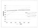
延伸後、セルロースエステルフィルム(CE−1)のコーティングおよび非コーティング部分の位相差(RthおよびRe)を、M−2000Vエリプソメータ(J.A.Woollam社)により測定した。波長589nmでの代表的な位相差、Re(589)およびRth(589)、ならびにRe(450)/Re(550)およびRe(650)/Re(550)の値を示す表1に結果をまとめる。フィルムの非コーティング部分と比較した場合、コーティングフィルムは、より低い面内位相差(Re)、低下した面外位相差の絶対値、図1に示すようなはるかに急峻な逆波長分散を有する点で特徴付けられる。このようにして得られたフィルムは、四分の一波長プレートの範囲である130nmのRe値を有する。 After stretching, the retardation (R th and R e ) of the coated and uncoated portions of the cellulose ester film (CE-1) was measured with an M-2000V ellipsometer (JA Woollam). Representative phase differences at wavelength 589 nm, R e (589) and R th (589), and R e (450) / R e (550) and R e (650) / R e (550) values are shown. Table 1 summarizes the results. When compared to the uncoated portion of the film, the coated film has a lower in-plane retardation (R e ), a reduced absolute value of out-of-plane retardation, and a much steeper inverse wavelength dispersion as shown in FIG. Characterized by dots. The film thus obtained, the has a R e value of 130nm in a range of a quarter-wave plate.

実施例2:セルロースエステルに基づく逆分散曲線を有する多層延伸フィルム2
実施例1に記載したように、第2のセルロースフィルムを調製し、PTFS溶液でコーティングした(乾燥コーティングの厚さ:11.91μm)。実施例1に従って、得られたフィルム(CE−2)を173℃で1.40の延伸比まで延伸した。結果を表2にまとめ、図2にプロットした。フィルムの非コーティング部分と比較した場合、コーティングフィルムは、図2に示すようなより低い面内位相差(Re)、低下した面外位相差の絶対値、およびはるかに急峻な逆波長分散を有する点で特徴付けられる。
Example 2: Multilayer stretched film 2 having an inverse dispersion curve based on cellulose ester
A second cellulose film was prepared and coated with a PTFS solution as described in Example 1 (dry coating thickness: 11.91 μm). According to Example 1, the resulting film (CE-2) was stretched at 173 ° C. to a stretch ratio of 1.40. The results are summarized in Table 2 and plotted in FIG. Compared to the uncoated portion of the film, the coated film exhibits a lower in-plane retardation (R e ), a reduced absolute out-of-plane retardation, and a much steeper inverse wavelength dispersion as shown in FIG. It is characterized by having.
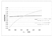
実施例3.セルロースエステルに基づく逆分散曲線を有する多層延伸フィルム3
実施例1に記載したように、第3のセルロースフィルムを調製し、PTFS溶液でコーティングした(乾燥コーティングの厚さ:17.79μm)。実施例1に従って、得られたフィルム(CE−3)を173℃で1.45の延伸比まで延伸した。結果を表3にまとめ、図3にプロットした。フィルムの非コーティング部分と比較した場合、コーティングフィルムは、図3に示すようなより低い面内位相差(Re)、低下した面外位相差の絶対値、およびはるかに急峻な逆波長分散を有する点で特徴付けられる。
Example 3 Multilayer stretched film 3 having inverse dispersion curve based on cellulose ester 3
A third cellulose film was prepared and coated with a PTFS solution as described in Example 1 (dry coating thickness: 17.79 μm). According to Example 1, the obtained film (CE-3) was stretched at 173 ° C. to a stretch ratio of 1.45. The results are summarized in Table 3 and plotted in FIG. When compared to the uncoated portion of the film, the coated film has a lower in-plane retardation (R e ), a reduced absolute value of out-of-plane retardation, and a much steeper inverse wavelength dispersion as shown in FIG. It is characterized by having.
実施例4:COPに基づく逆分散曲線を有する多層延伸フィルム
環状オレフィンポリマー(COP)フィルムを、この研究のためのベースフィルムとして使用した。このフィルムは、98μmの厚さ、ならびにRe(589)=3.41nmおよびRth(589)=−10.65nmの位相差を有し、本質的に光学等方性フィルムを示す。実施例1に記載したように、4種類のCOPフィルムを調製し(4インチ×4インチ)、PTFS溶液でコーティングした。実施例1に従って、得られたフィルム(COP−1〜COP−4)を、150℃で1.40〜1.5の範囲の延伸比まで延伸した。結果を表4にまとめる。このように得られたコーティングフィルムの分散曲線全ては、Re(450)/Re(550)およびRe(650)/Re(550)の値によって示されるように、逆波長分散特性を有するが、セルロースエステル系フィルムのものと比較して非常に平坦である。
Example 4: A multilayer stretched film cyclic olefin polymer (COP) film with an inverse dispersion curve based on COP was used as the base film for this study. This film has a thickness of 98 μm and a retardation of R e (589) = 3.41 nm and R th (589) = − 10.65 nm, essentially showing an optically isotropic film. As described in Example 1, four COP films were prepared (4 inches × 4 inches) and coated with a PTFS solution. According to Example 1, the obtained films (COP-1 to COP-4) were stretched at 150 ° C. to a stretch ratio in the range of 1.40 to 1.5. The results are summarized in Table 4. All of the dispersion curves of the coating film thus obtained have an inverse wavelength dispersion characteristic as indicated by the values of R e (450) / R e (550) and R e (650) / R e (550). Although it has, it is very flat compared with that of a cellulose ester film.
上記で実施形態を説明してきた。上記の方法および装置は、本発明の一般的な範囲から逸脱することなく変更および修正を組み込むことができることは当業者には明らかであろう。これは、添付の特許請求の範囲またはその等価物の範囲内にある限りにおいて、全てのそのような変更および修正を含むことを意図している。上記の説明は多くの特異性を含むが、これは本発明の範囲を限定するものとして解釈されるべきではなく、単に本発明の実施形態のいくつかの例示を提供するものとして解釈されるべきである。種々の他の実施形態および派生効果は、本発明の範囲内であり得る。 Embodiments have been described above. It will be apparent to those skilled in the art that the above methods and apparatus can incorporate changes and modifications without departing from the general scope of the invention. This is intended to include all such changes and modifications as long as they are within the scope of the appended claims or their equivalents. While the above description includes a number of specificities, this should not be construed as limiting the scope of the invention, but merely as providing some exemplifications of embodiments of the invention. It is. Various other embodiments and derived effects may be within the scope of the present invention.
さらに、本発明の広い範囲で示される数値範囲およびパラメータは近似値であるにもかかわらず、特定の実施例に示される数値は、できるだけ正確に報告される。しかし、任意の数値は、それぞれの試験測定に見られる標準偏差から必然的に生じる特定の誤差を本質的に含む。 Furthermore, despite the numerical ranges and parameters presented in the broad scope of the present invention are approximations, the numerical values shown in a particular embodiment are reported as accurately as possible. Any numerical value, however, inherently contains certain errors necessarily resulting from the standard deviation found in their respective testing measurements.
Claims (17)
(a)前記第1のポリマーフィルムは、(nx+ny)/2≧nzおよび|nx−ny|<0.005の式を満たす屈折率プロファイルを有し、前記第1のポリマーフィルムが、
1)nx=ny>nzの屈折率プロファイルを有する負のCプレートであって、かつ波長(λ)550nmにおいて−100nm〜−400nmの面外位相差(Rth)および20〜100μmの厚さを有するセルロースエステルフィルムを備える、負のCプレートであるか、または
2)nx=ny=nzの屈折率プロファイルを有する等方性フィルムであって、環状ポリオレフィン(COP)、ポリカーボネート、ポリエステル、ポリスルホンおよびアクリルポリマーからなる群から選択される、等方性フィルムであり、
(b)(nx+ny)/2<nzおよび|nx−ny|<0.005の式を満たす屈折率プロファイルを有する第2のポリマーフィルムであって、前記第2のポリマーフィルムが、nx=ny<nzの屈折率プロファイルを有する正のCプレートであり、かつ前記第2のポリマーフィルムが、
Δnth>0.01の式を満たす面外複屈折(Δnth)を有し、かつ
α,β,β−トリフルオロスチレン、α,β−ジフルオロスチレン、β,β−ジフルオロスチレン、α−フルオロスチレン、およびβ−フルオロスチレンからなる群から選択されるモノマーのホモポリマーまたはコポリマーである、第2のポリマーフィルムと、
を含み、
式中、nxおよびnyは前記フィルムの面内屈折率を表し、nzは前記フィルムの厚み方向屈折率を表し、前記光学補償フィルムは、0.7<R450/R550<1および1<R650/R550<1.25の関係を満たす正の面内位相差及び逆の面内波長分散特性を有し、R450、R550、およびR650は、それぞれ450nm、550nm、および650nmの光の波長での面内位相差であって、前記光学補償フィルムが、前記多層フィルムの一軸または二軸延伸によって作製され、前記多層フィルムが、前記第1のポリマーフィルムおよび前記第2のポリマーフィルムの組合せから作製され、かつ前記光学補償フィルムは、400nm〜800nmの範囲の波長全体にわたって|Rth|≦100nmの式を満たす面外位相差(Rth)を有する、
光学補償フィルム。 An optical compensation film, the optical compensation film comprising a first polymer film and a second polymer film forming a multilayer film, wherein
(A) said first polymer film, (n x + n y) / 2 ≧ n z and | n x -n y | has a refractive index profile satisfying <0.005 equations, the first polymer Film
1) A n x = n y> negative C plate having a refractive index profile of the n z, and the wavelength (lambda) out-of-plane retardation of -100nm~-400nm at 550 nm (R th) and 20~100μm of comprising a cellulose ester film having a thickness, or a negative C plate, or 2) a isotropic film having a refractive index profile of the n x = n y = n z , cyclic polyolefin (COP), polycarbonate An isotropic film selected from the group consisting of polyester, polysulfone and acrylic polymers,
(B) (n x + n y) / 2 <n z and | n x -n y | <a second polymer film having a refractive index profile satisfying 0.005 equations, the second polymer film There is a positive C plate having a refractive index profile of the n x = n y <n z , and the second polymer film,
It has an out-of-plane birefringence (Δn th ) satisfying the formula of Δn th > 0.01, and α, β, β-trifluorostyrene, α, β-difluorostyrene, β, β-difluorostyrene, α-fluoro A second polymer film that is a homopolymer or copolymer of a monomer selected from the group consisting of styrene and β-fluorostyrene;
Including
Wherein, n x and n y represent in-plane refractive index of the film, n z represents a thickness direction refractive index of the film, the optical compensation film, 0.7 <R 450 / R 550 <1 and 1 <R 650 / R 550 <1.25 with positive in-plane retardation and reverse in-plane chromatic dispersion characteristics satisfying the relationship, R 450 , R 550 , and R 650 are 450 nm, 550 nm, and An in-plane retardation at a wavelength of light of 650 nm, wherein the optical compensation film is made by uniaxial or biaxial stretching of the multilayer film, the multilayer film comprising the first polymer film and the second polymer film. made from a combination of polymer film, and the optical compensation film, 4 nm to 8 throughout the wavelength range of nm | Rth | satisfy the equation of ≦ 100 nm Having an out-of-plane phase difference (Rth),
Optical compensation film.
I.1種以上の有機溶媒にポリマーを溶解させてポリマー溶液を形成する工程(I)であって、前記ポリマーが、α,β,β−トリフルオロスチレン、α,β−ジフルオロスチレン、β,β−ジフルオロスチレン、α−フルオロスチレン、およびβ−フルオロスチレンを含む群から選択されるモノマーのホモポリマーまたはコポリマーを含有する、
工程(I)と;
II.前記ポリマー溶液を第1のポリマーフィルムに溶液キャスティングして前記第1のポリマーフィルム上にコーティングを作製する工程(II)であって、前記第1のポリマーフィルムが、
1)n x =n y >n z の屈折率プロファイルを有する負のCプレートであって、かつ波長(λ)550nmにおいて−100nm〜−400nmの面外位相差(R th )および20〜100μmの厚さを有するセルロースエステルフィルムを備える、負のCプレート、または
2)n x =n y =n z の屈折率プロファイルを有する等方性フィルムであって、環状ポリオレフィン(COP)、ポリカーボネート、ポリエステル、ポリスルホンおよびアクリルポリマーからなる群から選択される、等方性フィルム
である、
工程(II)と、
III.工程(II)で作製したコーティングを乾燥させて第2のポリマーフィルムを生成する工程(III)であって、
前記第1のポリマーフィルムおよび前記第2のポリマーフィルムは、延伸に適した多層フィルムを生成し、
前記第2のポリマーフィルムは、(nx+ny)/2<nzおよび|nx−ny|<0.005の式を満たす屈折率プロファイルを有し、かつ前記第2のポリマーフィルムが、正のCプレートであり、かつΔnth>0.01の式を満たす面外複屈折(Δnth)を有する、
工程(III)と、
IV.前記広視野光学補償フィルムの前記光学特性を提供することができる延伸比まで、適切な温度で前記多層フィルムを二軸または一軸延伸する工程(IV)であって、
式中、R450、R550、およびR650は、それぞれ450nm、550nm、および650nmの光の波長での面内位相差であり、nxおよびnyは面内屈折率を表し、nzは、前記第1のポリマーフィルムおよび前記第2のポリマーフィルムの厚み方向の屈折率を表す、
工程(IV)、
を包含する方法。 A method for producing a wide-field optical compensation film having a positive in-plane retardation satisfying a relationship of 0.7 <R 450 / R 550 <1 and 1 <R 650 / R 550 <1.25, Said method is:
I. A one or more organic solvents to dissolve the polymer to form a port Rimmer solution (I), wherein the polymer, α, β, β- trifluoromethyl styrene, alpha, beta-difluoro styrene, beta, beta Containing a homopolymer or copolymer of a monomer selected from the group comprising difluorostyrene, α-fluorostyrene, and β-fluorostyrene,
Step (I);
II. A front Kipo Rimmer solution a first polymer film solution casting to the step of producing a coating on said first polymer film (II), wherein the first polymer film,
1) A n x = n y> negative C plate having a refractive index profile of the n z, and the wavelength (lambda) out-of-plane retardation of -100nm~-400nm at 550 nm (R th) and 20~100μm of A negative C-plate comprising a cellulose ester film having a thickness, or
2) A isotropic film having a refractive index profile of the n x = n y = n z , cyclic polyolefin (COP), polycarbonate, polyester, selected from the group consisting of polysulfone and acrylic polymers, isotropic film
Is,
Step (II),
III. A step (III) in which the coating produced in step (II) is dried to produce a second polymer film,
The first polymer film and the second polymer film produce a multilayer film suitable for stretching;
The second polymer film is, (n x + n y) / 2 <n z and | has a refractive index profile satisfying <0.005 equations, and the second polymer film | n x -n y , a positive C plate, and to have a plane birefringence ([Delta] n th) satisfying the formula of [Delta] n th> 0.01,
Step (III);
IV. Step (IV) of biaxially or uniaxially stretching the multilayer film at an appropriate temperature up to a stretch ratio that can provide the optical properties of the wide-field optical compensation film ,
Wherein, R 450, R 550, and R 650 is an in-plane retardation at a wavelength of light of each 450 nm, 550 nm and 650 nm,, n x and n y represent in-plane refractive index, n z is Represents the refractive index in the thickness direction of the first polymer film and the second polymer film ,
Step (IV),
Including the method.
Applications Claiming Priority (3)
| Application Number | Priority Date | Filing Date | Title |
|---|---|---|---|
| US13/748,895 US9939554B2 (en) | 2013-01-24 | 2013-01-24 | Wide-view optical film having reversed wavelength dispersion |
| US13/748,895 | 2013-01-24 | ||
| PCT/US2014/012873 WO2014116901A1 (en) | 2013-01-24 | 2014-01-24 | Wide-view optical film having reversed wavelength dispersion |
Publications (3)
| Publication Number | Publication Date |
|---|---|
| JP2016511839A JP2016511839A (en) | 2016-04-21 |
| JP2016511839A5 JP2016511839A5 (en) | 2017-02-23 |
| JP6435277B2 true JP6435277B2 (en) | 2018-12-05 |
Family
ID=50193572
Family Applications (1)
| Application Number | Title | Priority Date | Filing Date |
|---|---|---|---|
| JP2015555294A Active JP6435277B2 (en) | 2013-01-24 | 2014-01-24 | Wide-field optical film with reverse wavelength dispersion |
Country Status (7)
| Country | Link |
|---|---|
| US (1) | US9939554B2 (en) |
| EP (1) | EP2948806B1 (en) |
| JP (1) | JP6435277B2 (en) |
| KR (1) | KR102147008B1 (en) |
| CN (1) | CN104937457B (en) |
| TW (1) | TWI560474B (en) |
| WO (1) | WO2014116901A1 (en) |
Families Citing this family (22)
| Publication number | Priority date | Publication date | Assignee | Title |
|---|---|---|---|---|
| KR101436441B1 (en) * | 2013-07-23 | 2014-09-02 | 동우 화인켐 주식회사 | Antireflective polarizing plate and image display apparatus comprising the same |
| KR101993736B1 (en) * | 2015-07-14 | 2019-06-28 | 주식회사 엘지화학 | Phase difference film, preparation method thereof and liquid crystal display device comprising the same |
| JP6301885B2 (en) | 2015-08-31 | 2018-03-28 | 日東電工株式会社 | Polarizing plate with optical compensation layer and organic EL panel using the same |
| US10640577B2 (en) * | 2016-04-22 | 2020-05-05 | Eastman Chemical Company | Regioselectively substituted cellulose esters and films made therefrom |
| KR102468247B1 (en) * | 2016-08-08 | 2022-11-16 | 니폰 제온 가부시키가이샤 | Optical anisotropic laminate, polarizer and image display device |
| KR102448215B1 (en) * | 2016-08-12 | 2022-09-27 | 아크론 폴리머 시스템즈, 인코포레이티드 | Multilayer Optical Compensation Film with Inverse Wavelength Dispersion |
| EP3497492B1 (en) * | 2016-08-12 | 2021-12-08 | Akron Polymer Systems, Inc. | Optical compensation film having reversed wavelength dispersion |
| WO2018031886A1 (en) * | 2016-08-12 | 2018-02-15 | Akron Polymer Systems, Inc. | Optical compensation films based on styrenic fluoropolymer |
| EP3497137A4 (en) | 2016-08-12 | 2020-06-10 | Akron Polymer Systems, Inc. | Method for the preparation of nitrated styrenic fluoropolymers |
| CN109964171B (en) * | 2016-11-11 | 2022-03-08 | 依视路国际公司 | Phase modulator and optical device |
| KR20180062231A (en) | 2016-11-30 | 2018-06-08 | 삼성전자주식회사 | Compensation film and antireflective film and display device |
| EP3601369A1 (en) * | 2017-03-29 | 2020-02-05 | Eastman Chemical Company | Regioselectively substituted cellulose esters |
| KR102165715B1 (en) * | 2018-08-08 | 2020-10-14 | 한양대학교 산학협력단 | Plate for Preventing Reflection of Incident Light and the Manufacturing Method thereof |
| AU2019358207A1 (en) * | 2018-10-12 | 2021-05-13 | Gary Sharp Innovations, Inc. | Polarization-based filters with angle-sensitive transmission |
| KR102434542B1 (en) * | 2018-10-15 | 2022-08-19 | 삼성에스디아이 주식회사 | Polarizing plate for ips liquid crystal display apparatus and ips liquid crystal display apparatus comprising the same |
| KR102435570B1 (en) * | 2018-12-18 | 2022-08-22 | 삼성에스디아이 주식회사 | Polarizing plate and optical display apparatus comprising the same |
| KR102457502B1 (en) * | 2018-12-27 | 2022-10-21 | 삼성에스디아이 주식회사 | Polarizing plate and liquid crystal display apparatus comprising the same |
| JP6712335B2 (en) * | 2019-01-16 | 2020-06-17 | 日東電工株式会社 | Polarizing plate with optical compensation layer and organic EL panel using the same |
| JPWO2021153695A1 (en) * | 2020-01-30 | 2021-08-05 | ||
| US11215743B2 (en) * | 2020-03-05 | 2022-01-04 | Facebook Technologies, Llc | Achromatic optical device based on birefringent materials having positive and negative birefringence dispersions |
| KR20230041264A (en) * | 2021-09-17 | 2023-03-24 | 동아대학교 산학협력단 | Organic light emitting diode optic compensation film for improvement of optical properties |
| CN114539631B (en) * | 2022-01-30 | 2023-03-10 | 中国科学技术大学 | Cellulose triacetate NRZ type optical compensation film and preparation method and application thereof |
Family Cites Families (16)
| Publication number | Priority date | Publication date | Assignee | Title |
|---|---|---|---|---|
| JP2000227520A (en) | 1999-02-08 | 2000-08-15 | Nitto Denko Corp | Phase difference plate, laminated polarizing plate and liquid crystal display device |
| EP1654585B1 (en) * | 2003-08-14 | 2013-07-24 | LG Chemical, Ltd. | Liquid crystal display comprising complex light-compensation c plate with two or more of c plates different in dispersion ratio value |
| CN1977192B (en) | 2004-06-29 | 2010-05-12 | 夏普株式会社 | Phase difference film, polarization film, liquid crystal display unit, and method of designing phase difference film |
| US7480021B2 (en) | 2005-12-29 | 2009-01-20 | Nitto Denko Corporation | Optical films having reverse dispersion |
| JP2007328052A (en) * | 2006-06-06 | 2007-12-20 | Dainippon Printing Co Ltd | Retardation film and its manufacturing method |
| TWI406899B (en) | 2006-09-05 | 2013-09-01 | Tosoh Corp | Optical compensation film and phase difference film |
| JP2008191407A (en) * | 2007-02-05 | 2008-08-21 | Dainippon Printing Co Ltd | Retardation film |
| US9834516B2 (en) * | 2007-02-14 | 2017-12-05 | Eastman Chemical Company | Regioselectively substituted cellulose esters produced in a carboxylated ionic liquid process and products produced therefrom |
| US8821994B2 (en) | 2007-03-29 | 2014-09-02 | Akron Polymer Systems | Liquid crystal display having improved wavelength dispersion characteristics |
| US9096719B2 (en) | 2007-03-29 | 2015-08-04 | Akron Polymer Systems | Optical compensation films with mesogen groups for liquid crystal display |
| US8304079B2 (en) | 2007-03-29 | 2012-11-06 | Akron Polymer Systems | Optical compensation films with birefringence enhancing substituents for liquid crystal display |
| US8802238B2 (en) | 2007-03-29 | 2014-08-12 | Akron Polymer Systems, Inc. | Optical compensation films based on fluoropolymers |
| US7989036B2 (en) | 2007-03-29 | 2011-08-02 | Akron Polymer Systems | Optical compensation films with disk groups for liquid crystal display |
| US8329893B2 (en) * | 2007-08-24 | 2012-12-11 | Eastman Chemical Company | Cellulose ester compositions having low birefringence and films made therefrom |
| US20120003403A1 (en) | 2010-07-02 | 2012-01-05 | Eastman Chemical Company | Multilayer cellulose ester film having reversed optical dispersion |
| US9377571B2 (en) | 2011-08-05 | 2016-06-28 | Lg Chem, Ltd. | Optical film |
-
2013
- 2013-01-24 US US13/748,895 patent/US9939554B2/en active Active
-
2014
- 2014-01-23 TW TW103102547A patent/TWI560474B/en active
- 2014-01-24 EP EP14707860.4A patent/EP2948806B1/en active Active
- 2014-01-24 KR KR1020157022418A patent/KR102147008B1/en active IP Right Grant
- 2014-01-24 WO PCT/US2014/012873 patent/WO2014116901A1/en active Application Filing
- 2014-01-24 JP JP2015555294A patent/JP6435277B2/en active Active
- 2014-01-24 CN CN201480005423.0A patent/CN104937457B/en active Active
Also Published As
| Publication number | Publication date |
|---|---|
| TWI560474B (en) | 2016-12-01 |
| EP2948806B1 (en) | 2022-04-06 |
| CN104937457A (en) | 2015-09-23 |
| CN104937457B (en) | 2019-01-25 |
| EP2948806A1 (en) | 2015-12-02 |
| JP2016511839A (en) | 2016-04-21 |
| US20140205822A1 (en) | 2014-07-24 |
| US9939554B2 (en) | 2018-04-10 |
| KR20150111954A (en) | 2015-10-06 |
| WO2014116901A1 (en) | 2014-07-31 |
| TW201439607A (en) | 2014-10-16 |
| KR102147008B1 (en) | 2020-08-21 |
Similar Documents
| Publication | Publication Date | Title |
|---|---|---|
| JP6435277B2 (en) | Wide-field optical film with reverse wavelength dispersion | |
| JP4618675B2 (en) | Retardation film, polarizing element, liquid crystal panel, and liquid crystal display device | |
| KR102057611B1 (en) | Inverse dispertion phase retardation film and display having the same | |
| WO2018164126A1 (en) | Organic electroluminescence display device, phase difference film, and circularly polarizing plate | |
| JP5308700B2 (en) | Polarizing plate and liquid crystal display device using the same | |
| JP4794015B2 (en) | Multilayer optical compensator | |
| JP2016502683A (en) | Wide-field multilayer optical film | |
| KR20160118383A (en) | Retardation film and process for producing same, polarizing plate, and display device | |
| JP2007140127A (en) | Polarizer, method for manufacturing the same, optical film and image display device | |
| TW200835980A (en) | Liquid crystal panel, and liquid crystal display | |
| CN115315644A (en) | Optically anisotropic layer, optical film, polarizing plate, and image display device | |
| JP2007328324A (en) | Liquid crystal panel and liquid crystal display device | |
| JP2020148882A (en) | Image display device, and circular polarizer to be used in the same | |
| KR101719056B1 (en) | Preparing method for the optical film, optical film by the same method, polarizing plate and liquid crystal display comprising the same | |
| KR102006037B1 (en) | Cellulose triacetate films with low birefringence | |
| TW201326990A (en) | Liquid crystal display apparatus | |
| KR102481465B1 (en) | Retardation film, polarizing plate and display device comprising the same | |
| JP2005221783A (en) | Birefringent film, optical film, polarizing plate, and liquid crystal display device | |
| JP2007121995A (en) | Method for manufacturing optical compensation film | |
| KR20170062278A (en) | Optical film and liquid crystal display | |
| KR102043492B1 (en) | Preparing method for the optical film, optical mamber and optical film by the same method, polarizing plate and liquid crystal display comprising the same | |
| CN116438478A (en) | Optical display device module and optical display device including the same | |
| JP2004070346A (en) | Polycarbonate-based oriented film and optical retardation film | |
| CN114252948A (en) | Polarizing plate and optical display including the same | |
| JP2013186210A (en) | Liquid crystal display device |
Legal Events
| Date | Code | Title | Description |
|---|---|---|---|
| A521 | Request for written amendment filed |
Free format text: JAPANESE INTERMEDIATE CODE: A523 Effective date: 20170117 |
|
| A621 | Written request for application examination |
Free format text: JAPANESE INTERMEDIATE CODE: A621 Effective date: 20170117 |
|
| A977 | Report on retrieval |
Free format text: JAPANESE INTERMEDIATE CODE: A971007 Effective date: 20170929 |
|
| A131 | Notification of reasons for refusal |
Free format text: JAPANESE INTERMEDIATE CODE: A131 Effective date: 20171128 |
|
| A521 | Request for written amendment filed |
Free format text: JAPANESE INTERMEDIATE CODE: A523 Effective date: 20180227 |
|
| A131 | Notification of reasons for refusal |
Free format text: JAPANESE INTERMEDIATE CODE: A131 Effective date: 20180703 |
|
| A521 | Request for written amendment filed |
Free format text: JAPANESE INTERMEDIATE CODE: A523 Effective date: 20181001 |
|
| TRDD | Decision of grant or rejection written | ||
| A01 | Written decision to grant a patent or to grant a registration (utility model) |
Free format text: JAPANESE INTERMEDIATE CODE: A01 Effective date: 20181106 |
|
| A61 | First payment of annual fees (during grant procedure) |
Free format text: JAPANESE INTERMEDIATE CODE: A61 Effective date: 20181112 |
|
| R150 | Certificate of patent or registration of utility model |
Ref document number: 6435277 Country of ref document: JP Free format text: JAPANESE INTERMEDIATE CODE: R150 |
|
| R250 | Receipt of annual fees |
Free format text: JAPANESE INTERMEDIATE CODE: R250 |
|
| R250 | Receipt of annual fees |
Free format text: JAPANESE INTERMEDIATE CODE: R250 |
|
| R250 | Receipt of annual fees |
Free format text: JAPANESE INTERMEDIATE CODE: R250 |